Development of an integral system for aero photogrammetric ... · photogrammetric flight planning,...
10
Jul 2008 Page 1 AeroDreams VEHICULOS AEREOS NO TRIPULADOS Av. Madero 900 Piso 24 – C1001AFB Buenos Aires, ARGENTINA Tel/Fax: (54-11) 4393-3466 (rot.) [email protected] www.aerodreams-uav.com This document includes proprietary and copyrighted material and information that shall not be disclosed, and shall not be duplicated, used or disclosed, in whole or in part for any purpose without written authorization of AeroDreams Development of an integral system for aero photogrammetric flight planning, data acquisition and imagery ortho-mosaicking Federico Cosentino AeroDreams UAV Buenos Aires, Argentina [email protected] www.aerodreams-uav.com I. Abstract This article summarizes the development carried out by AeroDreams UAV to turn the ADS-101 Strix UAV into a powerful tool for high resolution aerial mapping and data acquisition. This was possible through the automation of flight planning, improvements on data acquisition system and the automation of imagery ortho-mosaicking. Early in the development of the multipurpose Strix UAV, the Company was concerned about the integration of a complex system for data acquisition, including a small or medium format photographic camera mounted on a stabilized platform, and the processing power needed aboard to control autonomously both camera and platform, saving image data for post processing purposes, all within 5 kg or less. In the absence of an off-the-shelf airborne product (mainly supplied for manned aircrafts), the Company was forced to develop a complete system including the camera’s stabilized platform, reflex camera and aboard computer integration and control software. In order to automate data acquisition in vast areas, a complete module of the DreamNav GCS software was developed for flight planning. To manage large volumes of aerial imagery and mosaic generation, an automatic method was successfully tested. II. Introduction AeroDreams is the Argentinean leading company in the development, production and services with unmanned aerial vehicles (UAVs) for surveillance, reconnaissance and aerial mapping. Among the developed products and projects is the ADS-101 Strix, a fully tested small to medium-sized multipurpose UAV platform of up to 6 hour endurance and 8 kg payload capacity, in production and service since 2006. Fig. 1: Strix UAV equipped with stabilized photo camera.
Transcript of Development of an integral system for aero photogrammetric ... · photogrammetric flight planning,...
Jul 2008 Page 1
AeroDreams VEHICULOS AEREOS NO TRIPULADOS
Av. Madero 900 Piso 24 – C1001AFB Buenos Aires, ARGENTINA Tel/Fax: (54-11) 4393-3466 (rot.) [email protected] www.aerodreams-uav.com
This document includes proprietary and copyrighted material and information that shall not be disclosed, and shall not be duplicated, used or disclosed, in whole or in part for any purpose without written authorization of AeroDreams
Development of an integral system for aero photogrammetric flight planning, data acquisition and
imagery ortho-mosaicking
Federico Cosentino AeroDreams UAV
Buenos Aires, Argentina [email protected]
www.aerodreams-uav.com
I. Abstract This article summarizes the development carried out by AeroDreams UAV to turn the ADS-101
Strix UAV into a powerful tool for high resolution aerial mapping and data acquisition. This was possible through the automation of flight planning, improvements on data acquisition system and the automation of imagery ortho-mosaicking.
Early in the development of the multipurpose Strix UAV, the Company was concerned about the integration of a complex system for data acquisition, including a small or medium format photographic camera mounted on a stabilized platform, and the processing power needed aboard to control autonomously both camera and platform, saving image data for post processing purposes, all within 5 kg or less. In the absence of an off-the-shelf airborne product (mainly supplied for manned aircrafts), the Company was forced to develop a complete system including the camera’s stabilized platform, reflex camera and aboard computer integration and control software.
In order to automate data acquisition in vast areas, a complete module of the DreamNav GCS software was developed for flight planning. To manage large volumes of aerial imagery and mosaic generation, an automatic method was successfully tested.
II. Introduction AeroDreams is the Argentinean leading company in the development, production and services
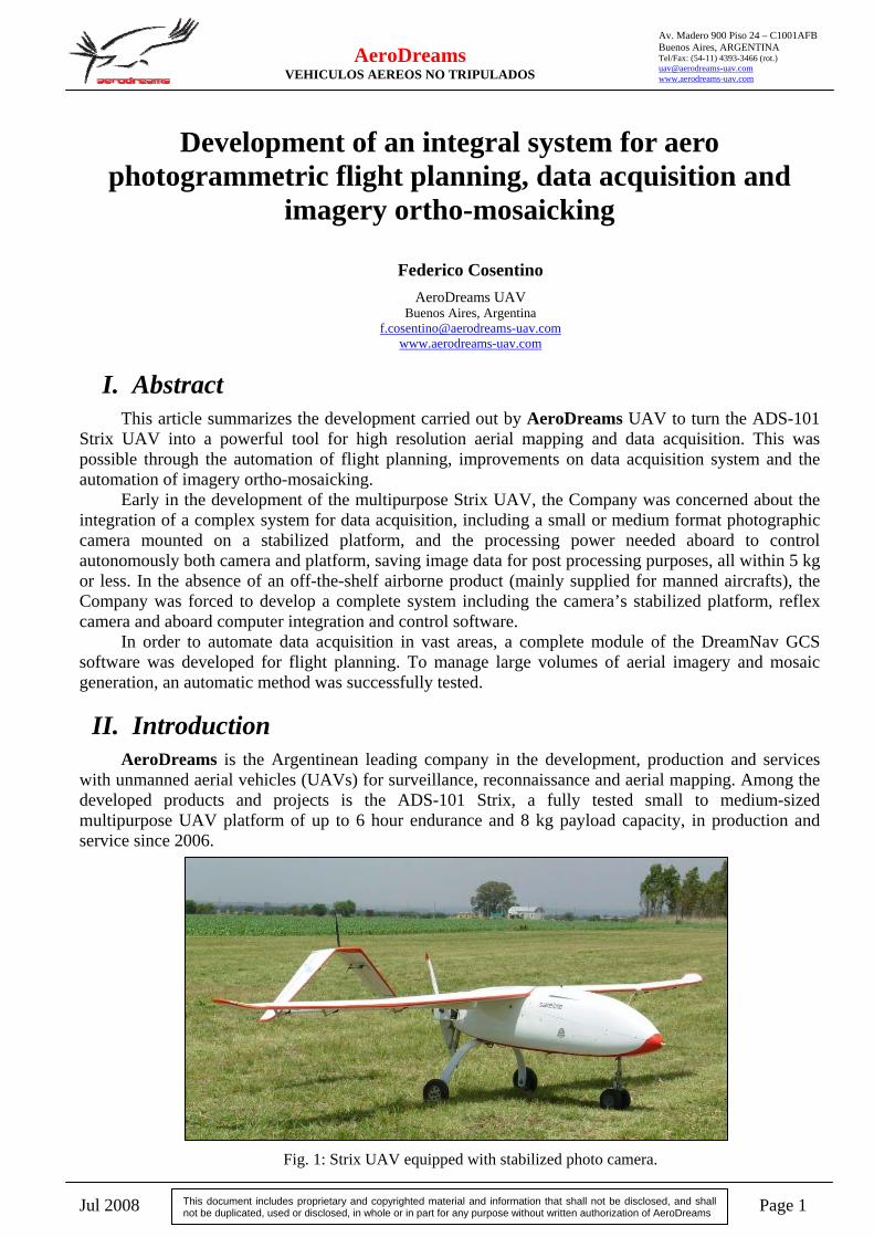
with unmanned aerial vehicles (UAVs) for surveillance, reconnaissance and aerial mapping. Among the developed products and projects is the ADS-101 Strix, a fully tested small to medium-sized multipurpose UAV platform of up to 6 hour endurance and 8 kg payload capacity, in production and service since 2006.
Fig. 1: Strix UAV equipped with stabilized photo camera.
Jul 2008 Page 2
AeroDreams VEHICULOS AEREOS NO TRIPULADOS
Av. Madero 900 Piso 24 – C1001AFB Buenos Aires, ARGENTINA Tel/Fax: (54-11) 4393-3466 (rot.) [email protected] www.aerodreams-uav.com
This document includes proprietary and copyrighted material and information that shall not be disclosed, and shall not be duplicated, used or disclosed, in whole or in part for any purpose without written authorization of AeroDreams
The Strix can be equipped with a wide range of EO/IR and electronic sensors, including stabilized camera gimbals and aerial photogrammetry platforms for high resolution imagery. An aboard computer control both the stabilized platform and the camera, among a wide variety of electronic sensors, opening the possibility of equipment customization. Communications to ground control station (GCS) are carried out via UHF or satellite data link through Iridium system.
Several Strix in service have flown more than 300 hours and have surveyed and collected images in more than 250000 hectares just in the current year 2008.
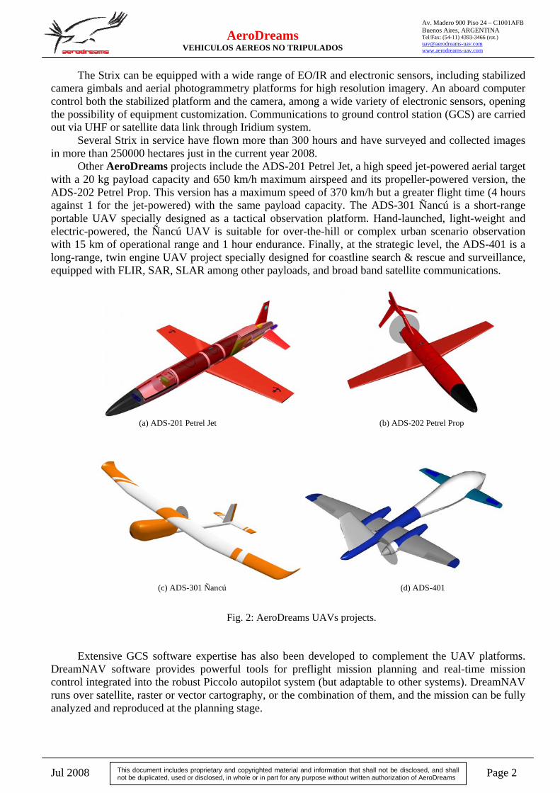
Other AeroDreams projects include the ADS-201 Petrel Jet, a high speed jet-powered aerial target with a 20 kg payload capacity and 650 km/h maximum airspeed and its propeller-powered version, the ADS-202 Petrel Prop. This version has a maximum speed of 370 km/h but a greater flight time (4 hours against 1 for the jet-powered) with the same payload capacity. The ADS-301 Ñancú is a short-range portable UAV specially designed as a tactical observation platform. Hand-launched, light-weight and electric-powered, the Ñancú UAV is suitable for over-the-hill or complex urban scenario observation with 15 km of operational range and 1 hour endurance. Finally, at the strategic level, the ADS-401 is a long-range, twin engine UAV project specially designed for coastline search & rescue and surveillance, equipped with FLIR, SAR, SLAR among other payloads, and broad band satellite communications.
(a) ADS-201 Petrel Jet (b) ADS-202 Petrel Prop
(c) ADS-301 Ñancú (d) ADS-401
Fig. 2: AeroDreams UAVs projects.
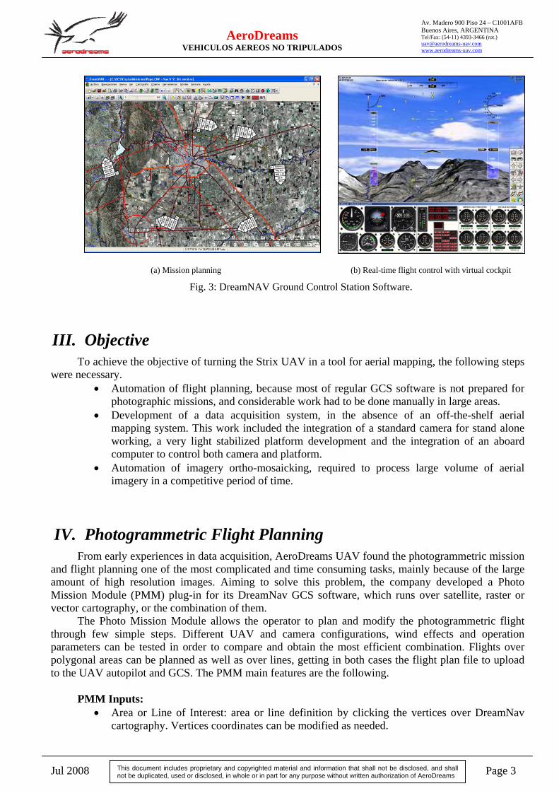
Extensive GCS software expertise has also been developed to complement the UAV platforms.
DreamNAV software provides powerful tools for preflight mission planning and real-time mission control integrated into the robust Piccolo autopilot system (but adaptable to other systems). DreamNAV runs over satellite, raster or vector cartography, or the combination of them, and the mission can be fully analyzed and reproduced at the planning stage.
Jul 2008 Page 3
AeroDreams VEHICULOS AEREOS NO TRIPULADOS
Av. Madero 900 Piso 24 – C1001AFB Buenos Aires, ARGENTINA Tel/Fax: (54-11) 4393-3466 (rot.) [email protected] www.aerodreams-uav.com
This document includes proprietary and copyrighted material and information that shall not be disclosed, and shall not be duplicated, used or disclosed, in whole or in part for any purpose without written authorization of AeroDreams
(a) Mission planning (b) Real-time flight control with virtual cockpit
Fig. 3: DreamNAV Ground Control Station Software.
III. Objective To achieve the objective of turning the Strix UAV in a tool for aerial mapping, the following steps
were necessary. • Automation of flight planning, because most of regular GCS software is not prepared for
photographic missions, and considerable work had to be done manually in large areas. • Development of a data acquisition system, in the absence of an off-the-shelf aerial
mapping system. This work included the integration of a standard camera for stand alone working, a very light stabilized platform development and the integration of an aboard computer to control both camera and platform.
• Automation of imagery ortho-mosaicking, required to process large volume of aerial imagery in a competitive period of time.
IV. Photogrammetric Flight Planning From early experiences in data acquisition, AeroDreams UAV found the photogrammetric mission
and flight planning one of the most complicated and time consuming tasks, mainly because of the large amount of high resolution images. Aiming to solve this problem, the company developed a Photo Mission Module (PMM) plug-in for its DreamNav GCS software, which runs over satellite, raster or vector cartography, or the combination of them.
The Photo Mission Module allows the operator to plan and modify the photogrammetric flight through few simple steps. Different UAV and camera configurations, wind effects and operation parameters can be tested in order to compare and obtain the most efficient combination. Flights over polygonal areas can be planned as well as over lines, getting in both cases the flight plan file to upload to the UAV autopilot and GCS. The PMM main features are the following.
PMM Inputs:
• Area or Line of Interest: area or line definition by clicking the vertices over DreamNav cartography. Vertices coordinates can be modified as needed.
Jul 2008 Page 4
AeroDreams VEHICULOS AEREOS NO TRIPULADOS
Av. Madero 900 Piso 24 – C1001AFB Buenos Aires, ARGENTINA Tel/Fax: (54-11) 4393-3466 (rot.) [email protected] www.aerodreams-uav.com
This document includes proprietary and copyrighted material and information that shall not be disclosed, and shall not be duplicated, used or disclosed, in whole or in part for any purpose without written authorization of AeroDreams
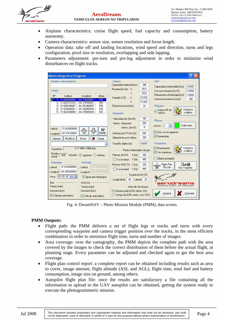
• Airplane characteristics: cruise flight speed, fuel capacity and consumption, battery autonomy.
• Camera characteristics: sensor size, sensor resolution and focus length. • Operation data: take off and landing locations, wind speed and direction, turns and legs
configuration, pixel size or resolution, overlapping and side lapping. • Parameters adjustment: pre-turn and pre-leg adjustment in order to minimize wind
disturbances on flight tracks.
Fig. 4: DreamNAV – Photo Mission Module (PMM), data screen. PMM Outputs:
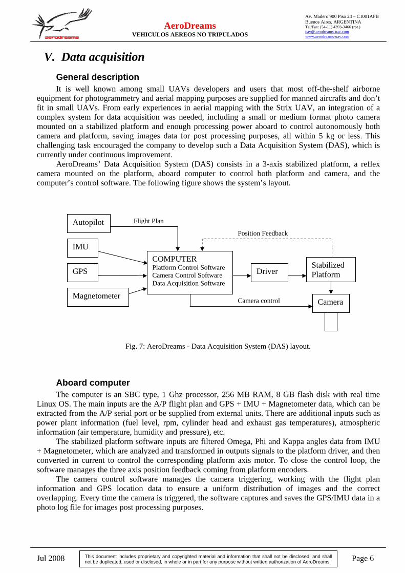
• Flight path: the PMM delivers a set of flight legs or tracks and turns with every corresponding waypoint and camera trigger position over the tracks, in the most efficient combination in order to minimize flight time, turns and number of images.
• Area coverage: over the cartography, the PMM depicts the complete path with the area covered by the images to check the correct distribution of them before the actual flight, at planning stage. Every parameter can be adjusted and checked again to get the best area coverage.
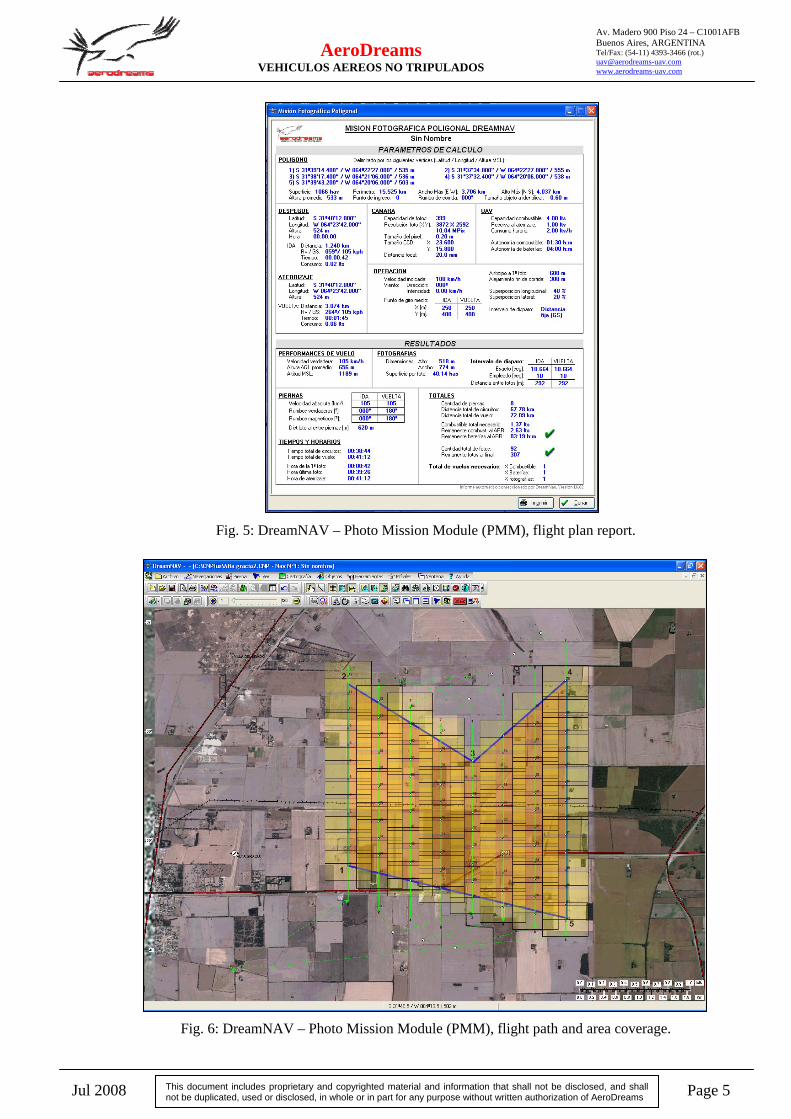
• Flight plan control report: a complete report can be obtained including results such as area to cover, image amount, flight altitude (ASL and AGL), flight time, total fuel and battery consumption, image size on ground, among others.
• Autopilot flight plan file: once the results are satisfactory a file containing all the information to upload to the UAV autopilot can be obtained, getting the system ready to execute the photogrammetric mission.
Jul 2008 Page 5
AeroDreams VEHICULOS AEREOS NO TRIPULADOS
Av. Madero 900 Piso 24 – C1001AFB Buenos Aires, ARGENTINA Tel/Fax: (54-11) 4393-3466 (rot.) [email protected] www.aerodreams-uav.com
This document includes proprietary and copyrighted material and information that shall not be disclosed, and shall not be duplicated, used or disclosed, in whole or in part for any purpose without written authorization of AeroDreams
Fig. 5: DreamNAV – Photo Mission Module (PMM), flight plan report.
Fig. 6: DreamNAV – Photo Mission Module (PMM), flight path and area coverage.
Jul 2008 Page 6
AeroDreams VEHICULOS AEREOS NO TRIPULADOS
Av. Madero 900 Piso 24 – C1001AFB Buenos Aires, ARGENTINA Tel/Fax: (54-11) 4393-3466 (rot.) [email protected] www.aerodreams-uav.com
This document includes proprietary and copyrighted material and information that shall not be disclosed, and shall not be duplicated, used or disclosed, in whole or in part for any purpose without written authorization of AeroDreams
V. Data acquisition General description It is well known among small UAVs developers and users that most off-the-shelf airborne
equipment for photogrammetry and aerial mapping purposes are supplied for manned aircrafts and don’t fit in small UAVs. From early experiences in aerial mapping with the Strix UAV, an integration of a complex system for data acquisition was needed, including a small or medium format photo camera mounted on a stabilized platform and enough processing power aboard to control autonomously both camera and platform, saving images data for post processing purposes, all within 5 kg or less. This challenging task encouraged the company to develop such a Data Acquisition System (DAS), which is currently under continuous improvement.
AeroDreams’ Data Acquisition System (DAS) consists in a 3-axis stabilized platform, a reflex camera mounted on the platform, aboard computer to control both platform and camera, and the computer’s control software. The following figure shows the system’s layout.
Fig. 7: AeroDreams - Data Acquisition System (DAS) layout.
Aboard computer The computer is an SBC type, 1 Ghz processor, 256 MB RAM, 8 GB flash disk with real time
Linux OS. The main inputs are the A/P flight plan and GPS + IMU + Magnetometer data, which can be extracted from the A/P serial port or be supplied from external units. There are additional inputs such as power plant information (fuel level, rpm, cylinder head and exhaust gas temperatures), atmospheric information (air temperature, humidity and pressure), etc.
The stabilized platform software inputs are filtered Omega, Phi and Kappa angles data from IMU + Magnetometer, which are analyzed and transformed in outputs signals to the platform driver, and then converted in current to control the corresponding platform axis motor. To close the control loop, the software manages the three axis position feedback coming from platform encoders.
The camera control software manages the camera triggering, working with the flight plan information and GPS location data to ensure a uniform distribution of images and the correct overlapping. Every time the camera is triggered, the software captures and saves the GPS/IMU data in a photo log file for images post processing purposes.
Position Feedback
Camera control
Flight Plan
IMU
GPS Stabilized Platform
Camera
COMPUTER Platform Control Software Camera Control Software Data Acquisition Software
Magnetometer
Driver
Autopilot
Jul 2008 Page 7
AeroDreams VEHICULOS AEREOS NO TRIPULADOS
Av. Madero 900 Piso 24 – C1001AFB Buenos Aires, ARGENTINA Tel/Fax: (54-11) 4393-3466 (rot.) [email protected] www.aerodreams-uav.com
This document includes proprietary and copyrighted material and information that shall not be disclosed, and shall not be duplicated, used or disclosed, in whole or in part for any purpose without written authorization of AeroDreams
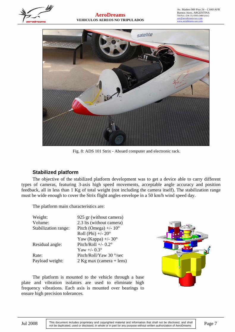
Fig. 8: ADS 101 Strix - Aboard computer and electronic rack.
Stabilized platform The objective of the stabilized platform development was to get a device able to carry different
types of cameras, featuring 3-axis high speed movements, acceptable angle accuracy and position feedback, all in less than 1 Kg of total weight (not including the camera itself). The stabilization range must be wide enough to cover the Strix flight angles envelope in a 50 km/h wind speed day.
The platform main characteristics are: Weight: 925 gr (without camera) Volume: 2.3 lts (without camera) Stabilization range: Pitch (Omega) +/- 10° Roll (Phi) +/- 20° Yaw (Kappa) +/- 30° Residual angle: Pitch/Roll +/- 0.2° Yaw +/- 0.3° Rate: Pitch/Roll/Yaw 30 °/sec Payload weight: 2 Kg max (camera + lens) The platform is mounted to the vehicle through a base
plate and vibration isolators are used to eliminate high frequency vibrations. Each axis is mounted over bearings to ensure high precision tolerances.
Jul 2008 Page 8
AeroDreams VEHICULOS AEREOS NO TRIPULADOS
Av. Madero 900 Piso 24 – C1001AFB Buenos Aires, ARGENTINA Tel/Fax: (54-11) 4393-3466 (rot.) [email protected] www.aerodreams-uav.com
This document includes proprietary and copyrighted material and information that shall not be disclosed, and shall not be duplicated, used or disclosed, in whole or in part for any purpose without written authorization of AeroDreams
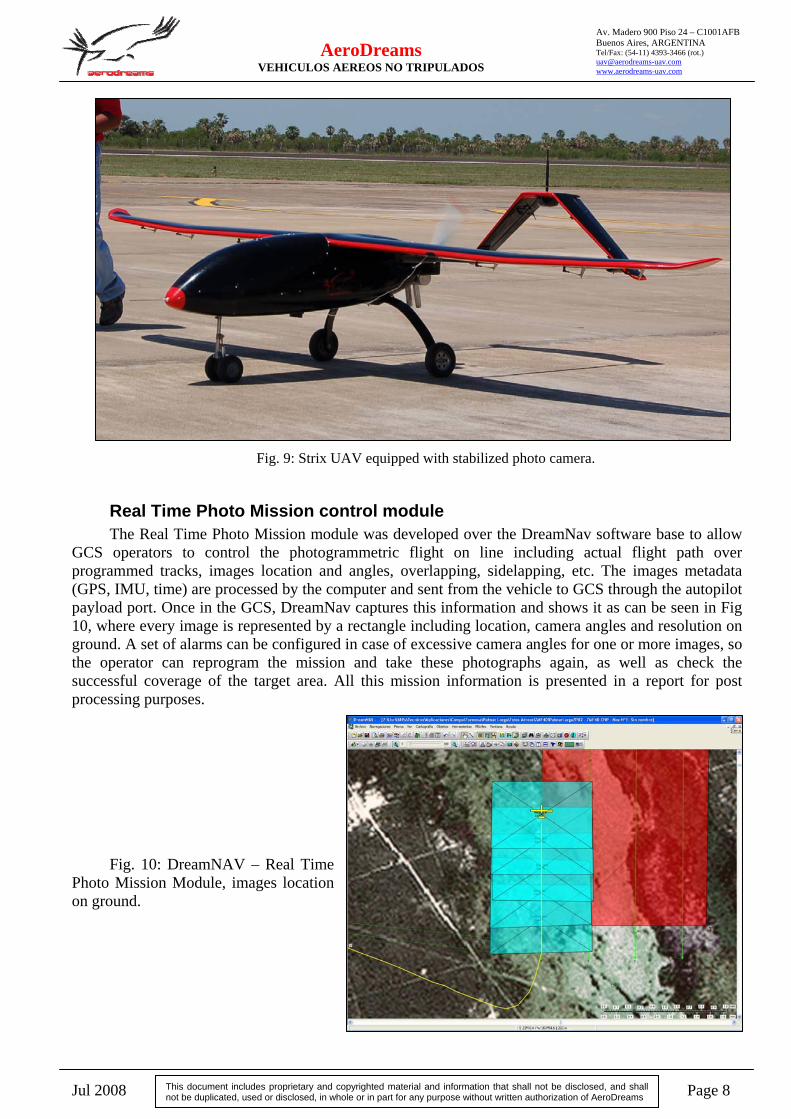
Fig. 9: Strix UAV equipped with stabilized photo camera.
Real Time Photo Mission control module The Real Time Photo Mission module was developed over the DreamNav software base to allow
GCS operators to control the photogrammetric flight on line including actual flight path over programmed tracks, images location and angles, overlapping, sidelapping, etc. The images metadata (GPS, IMU, time) are processed by the computer and sent from the vehicle to GCS through the autopilot payload port. Once in the GCS, DreamNav captures this information and shows it as can be seen in Fig 10, where every image is represented by a rectangle including location, camera angles and resolution on ground. A set of alarms can be configured in case of excessive camera angles for one or more images, so the operator can reprogram the mission and take these photographs again, as well as check the successful coverage of the target area. All this mission information is presented in a report for post processing purposes.
Fig. 10: DreamNAV – Real Time
Photo Mission Module, images location on ground.
Jul 2008 Page 9
AeroDreams VEHICULOS AEREOS NO TRIPULADOS
Av. Madero 900 Piso 24 – C1001AFB Buenos Aires, ARGENTINA Tel/Fax: (54-11) 4393-3466 (rot.) [email protected] www.aerodreams-uav.com
This document includes proprietary and copyrighted material and information that shall not be disclosed, and shall not be duplicated, used or disclosed, in whole or in part for any purpose without written authorization of AeroDreams
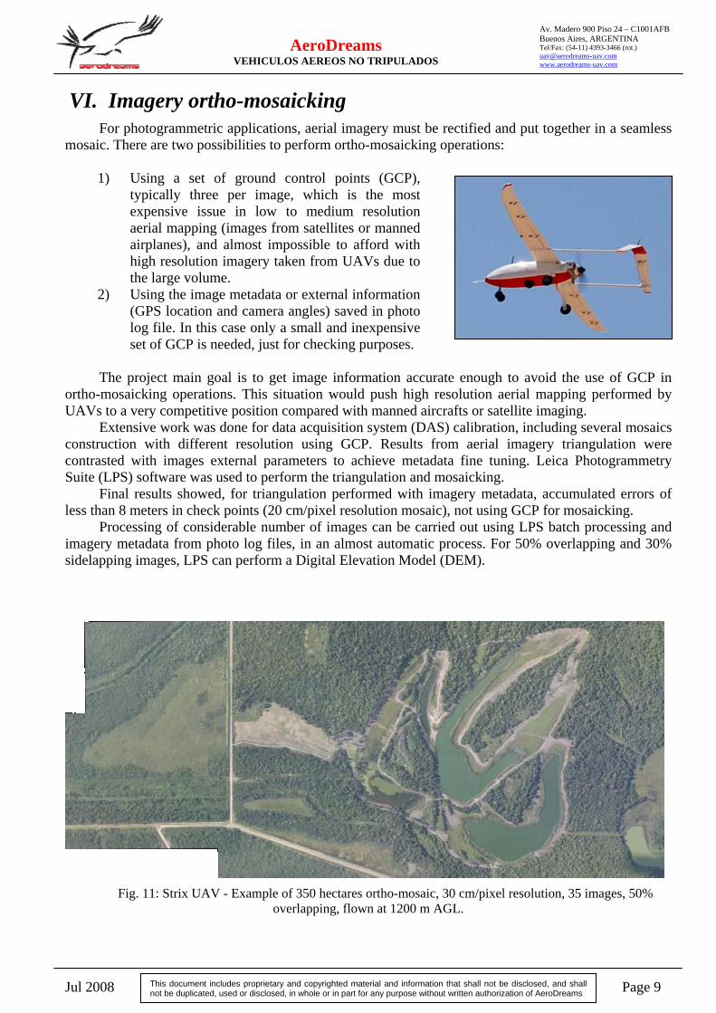
VI. Imagery ortho-mosaicking For photogrammetric applications, aerial imagery must be rectified and put together in a seamless
mosaic. There are two possibilities to perform ortho-mosaicking operations: 1) Using a set of ground control points (GCP),
typically three per image, which is the most expensive issue in low to medium resolution aerial mapping (images from satellites or manned airplanes), and almost impossible to afford with high resolution imagery taken from UAVs due to the large volume.
2) Using the image metadata or external information (GPS location and camera angles) saved in photo log file. In this case only a small and inexpensive set of GCP is needed, just for checking purposes.
The project main goal is to get image information accurate enough to avoid the use of GCP in
ortho-mosaicking operations. This situation would push high resolution aerial mapping performed by UAVs to a very competitive position compared with manned aircrafts or satellite imaging.
Extensive work was done for data acquisition system (DAS) calibration, including several mosaics construction with different resolution using GCP. Results from aerial imagery triangulation were contrasted with images external parameters to achieve metadata fine tuning. Leica Photogrammetry Suite (LPS) software was used to perform the triangulation and mosaicking.
Final results showed, for triangulation performed with imagery metadata, accumulated errors of less than 8 meters in check points (20 cm/pixel resolution mosaic), not using GCP for mosaicking.
Processing of considerable number of images can be carried out using LPS batch processing and imagery metadata from photo log files, in an almost automatic process. For 50% overlapping and 30% sidelapping images, LPS can perform a Digital Elevation Model (DEM).
Fig. 11: Strix UAV - Example of 350 hectares ortho-mosaic, 30 cm/pixel resolution, 35 images, 50% overlapping, flown at 1200 m AGL.
Jul 2008 Page 10
AeroDreams VEHICULOS AEREOS NO TRIPULADOS
Av. Madero 900 Piso 24 – C1001AFB Buenos Aires, ARGENTINA Tel/Fax: (54-11) 4393-3466 (rot.) [email protected] www.aerodreams-uav.com
This document includes proprietary and copyrighted material and information that shall not be disclosed, and shall not be duplicated, used or disclosed, in whole or in part for any purpose without written authorization of AeroDreams
VII. Conclusion The development presented in this paper was successfully tested over more than 250000 hectares
flown in three months by a fleet of 3 Strix UAVs in service from AeroDreams Company in the northern part of Argentina, operated by two teams of 4 persons, in 10 days shifts. The systems demonstrated highly reliable behavior, achieving as much productivity as almost 20000 hectares/day in some opportunities.
Future work on the subject will include the integration of a Differential GPS (DGPS) on the systems to increase mosaic precision without using GCP, in order to get errors within 1 meter or less. Integration of Multispectral cameras for agricultural application is another topic of interest for future work.
VIII. References
[1] Gonzalez E, Becker J – UAV stability derivatives estimation for hardware-in-the-loop simulation of Piccolo autopilot by qualitative flight testing - AeroDreams UAV, Aug 2007
[2] Medici A – DreamNav Ground Control Station Software, User’s Manual - AeroDreams UAV, Jul 2007
[3] Hinz A, Dorstel C, Heier H – DMC, The digital sensor techonology of Z/I Imaging - Z/I Imaging, 2001
[4] Leica – Leica Photogrammetry Suite, User’s Manual - Leica, 2006
[5] Underwood D – Novatel DGPS Integration Guide - Cloud Cap Technology, Nov 2007
[6] Jackobsen O, Johnson E – Control architecture for a UAV mounted pan/tilt/roll camera gimbal – Georgia Institute of Technology, Sep 2005
[7] McBride R, Cellier F – Object-oriented bond-graph modeling of a gyroscopically stabilized camera platform – Raytheon Missile Systems/University of Arizona
[8] Patterson M, Brescia A – Requirements driven UAV development – Advanced Ceramics Research / Naval Air Systems Command, Apr 2007
[9] Patterson M, Brescia A – Integrated sensor systems for UAS – Advanced Ceramics Research / Naval Air Systems Command, Apr 2008