Development of an Inkjet Printing System on a Flatbed Router
151
Development of an Inkjet Printing System on a Flatbed Router by Dayna Chan A thesis presented to the University of Waterloo in fulfillment of the thesis requirement for the degree of Master of Applied Science in Mechanical Engineering Waterloo, Ontario, Canada, 2010 © Dayna Chan 2010
Transcript of Development of an Inkjet Printing System on a Flatbed Router

Development of an Inkjet Printing
System on a Flatbed Router
by
Dayna Chan
A thesis
presented to the University of Waterloo
in fulfillment of the
thesis requirement for the degree of
Master of Applied Science
in
Mechanical Engineering
Waterloo, Ontario, Canada, 2010
© Dayna Chan 2010

ii
Author’s Declaration
I hereby declare that I am the sole author of this thesis. This is a true copy of the thesis, including any
required final revisions, as accepted by my examiners.
I understand that my thesis may be made electronically available to the public.
iii
Abstract
Manufactured products, such as furniture, laminate flooring, and large signs, are very labour
intensive, time-consuming, and costly to produce as they require multiple coating and cutting
operations on a series of independent machines, which can each introduce manufacturing errors
between the tools and the work piece. By combining the processes of printing and milling, printing
integrated manufacturing has the potential to eliminate some of these steps, significantly reduce errors,
and preserve resources. Inkjet printing is an ideal method for both image transfer and coating operations
due to its non-contact method of directly depositing various types of fluid onto a substrate. With
improved positioning accuracy and droplet miniaturisation, inkjet printing could even be used for future
applications like the mass-production of MEMS devices, which are traditionally fabricated with a
highly complex process involving photolithography.
This thesis presents the integration of a Xaar 126 inkjet printing system with an existing
industrial flatbed CNC router to develop a combined printing and cutting system. This integration
required modification to the overall system through mechanical, electrical, and software means to the
existing 3-axis CNC milling system. A secondary z-axis was installed onto the router gantry for
positioning of the printheads relative to the substrate, which required development of a separate homing
routine to consistently position the printheads to a specified location. Based on the identified frequency
response of the machine, a loop-shaping controller was designed for improved y-axis positioning,
which is one of the main contributions to droplet placement accuracy. This resulted in a continuous
motion tracking accuracy within ±20.2 µm at 250 mm/sec along a print pass (measured by 1.22 nm
resolution linear encoder), which is significantly better than the industrial benchmark of ±100 µm.
Extensive image processing and calibration methods were utilised on various substrate
preparations of paper, wood, and coatings, to demonstrate the capability of the printing system and
quantify the quality of print resolution. Calibration results tested on high-gloss Hewlett-Packard paper
showed that the swath angle could be aligned within ±1°. Also, bidirectional printing could be used to
reduce print time by at least 15% in multi-colour printing with comparable droplet placement accuracy
to unidirectional printing. The inkjet system was successfully used to print custom designs on paper
and, to a certain extent, on medium density fibreboard at a feed rate of 250 mm/sec. It was difficult to
achieve satisfactory image results on wood, as the wood or paint grain was visible through the ink.
Thus, without a white pre-coat, the printed image would appear significantly darker than the original
image, even after adjusting the image in a graphics editor. For better quality results, it is recommended
that greyscale printheads be implemented for greater resolution and a UV system should be investigated
for more versatility in printing on different substrates such as glass, metals, plastics, and ceramics.

iv
Acknowledgements
This research was funded in part by the Ontario Centres of Excellence. This project would not
have been possible in such a short time without the help of a great group of people at the University of
Waterloo. Robert Wagner, our laboratory’s CNC technician, provided invaluable advice and support in
the mechanical assembly of the router and printing system. Jason, Charlie, and Fred from the
Engineering Machine Shop did an amazing job machining components for the printing assembly and
were always friendly and helpful. Andy Barber and Neil Griffett were a great help in figuring out the
necessary electrical connections, building the signal converter and cables, and troubleshooting. AJung
Moon hugely facilitated in getting the project started with the motor and actuator selection and assisting
in the design of the printhead mounting assembly. Mark Podbevsek was a terrific help with his
knowledge of machinery and for machining components in preparation for the initial setup with the
Xaar field engineer. Greg Derrington was the field engineer from Xaar and he was an excellent advisor
in implementing the printing system, providing years of experience and knowledge, and giving
comprehensive instruction on using Xaar software. The redesign of the bottom plate for bidirectional
printing was completed with the help of Turker Izci. Jeff Gorniak, Ammar Alzaydi, and Sui Gao
roughed some of the plates for the printhead mount. Dan Gordon provided great insight in
implementing the Control Desk real-time program for manually controlling the router and general
discussion. Everyone here and the rest of the members from the Precision Controls Laboratory were a
tremendous support. Thanks for the good times.
To my thesis committee readers, Prof. Ehsan Toyserkani and Prof. Michael Mayer, thank you
for the great feedback and taking the time to review my thesis. I would like to thank my supervisor,
Prof. Kaan Erkorkmaz, for giving me the opportunity to work with such an exciting project. His
guidance and insight were an invaluable part of my experience.
Finally, I am very grateful to my friends and family, especially Jayna Chan, Heather Van
Winckle, and Rana Chan, for pushing me to finish and believing in me. See, I do listen to you. Thanks
to Ivan Chin, my main reason for getting a Master’s degree, for understanding and supporting me
(including distractions and food) through the good times and bad. I’ll get working on those robots
soon...

v
Dedication
This thesis is dedicated to my mom and dad.

vi
Table of Contents
Author’s Declaration ...................................................................................................................................... ii
Abstract ........................................................................................................................................................... iii
Acknowledgements ........................................................................................................................................ iv
Dedication ....................................................................................................................................................... v
List of Figures ................................................................................................................................................. viii
List of Tables .................................................................................................................................................. x
Chapter 1: Introduction to Printing Integrated Manufacturing ..................................................................... 1
Section 1.1: Applications ............................................................................................................................ 2
Section 1.2: Experimental Setup and Previous Work ................................................................................. 3
Section 1.3: Scope of Thesis ....................................................................................................................... 5
Chapter 2: Literature Review ........................................................................................................................ 6
Section 2.1: Printing Methods .................................................................................................................... 7
Section 2.2: Printing Resolution and Colour Generation ........................................................................... 13
Section 2.3: Theory of Droplet Formation in Inkjet Printing ..................................................................... 15
Section 2.3.1: Kinetics ........................................................................................................................... 21
Section 2.4: Recent Developments in Industrial Inkjet Printing Applications ........................................... 24
Section 2.5: Conclusions ............................................................................................................................ 26
Chapter 3: Design of a Flatbed Printing System ........................................................................................... 28
Section 3.1: Printing Component Selection ................................................................................................ 29
Section 3.2: System Integration .................................................................................................................. 34
Section 3.2.1: Mechanical Integration ................................................................................................... 36
Section 3.2.2: Electronics and Software Integration .............................................................................. 42
Section 3.3: Conclusions ............................................................................................................................ 44
Chapter 4: Servo System Design ................................................................................................................... 45
Section 4.1: Sliding Mode Controller Design............................................................................................. 47

vii
Section 4.2: Frequency Domain Identification of Axis Dynamics ............................................................. 50
Section 4.3: Loop-Shaping Controller Design ............................................................................................ 53
Section 4.4: Trajectory Generation & Axis Homing .................................................................................. 62
Section 4.5: Conclusions ............................................................................................................................ 70
Chapter 5: Inkjet Printing Calibration ........................................................................................................... 71
Section 5.1: Printhead Calibration Methodology and Operation ................................................................ 73
Section 5.2: Calibration Experiments ......................................................................................................... 77
Section 5.2.1: Unidirectional Monochrome Printing ............................................................................. 79
Section 5.2.2: Unidirectional Multi-colour Printing .............................................................................. 82
Section 5.2.3: Unidirectional Multi-swath Monochrome (Large Image) Printing ................................. 84
Section 5.2.4: Unidirectional Multi-swath Multi-colour Printing .......................................................... 89
Section 5.2.5: Bidirectional Monochrome Printing ............................................................................... 92
Section 5.2.6: Bidirectional Multi-colour Printing ............................................................................... 94
Section 5.3: Additional Issues .................................................................................................................... 98
Section 5.4: Conclusions ............................................................................................................................ 100
Chapter 6: Printing on Different Media ......................................................................................................... 101
Section 6.1: Conclusions ............................................................................................................................ 111
Chapter 7: Conclusions and Recommendations ............................................................................................ 112
References ...................................................................................................................................................... 115
Appendices:
Appendix A: Xaar Printhead Specifications ................................................................................................... 118
Appendix B: Printhead Angle Calculations .................................................................................................... 119
Appendix C: Operation of Printing System .................................................................................................... 123
Appendix D: Additional Calibration Measurements and Calculations ........................................................... 138

viii
List of Figures
Figure 1.1: Industrial Flatbed Router .............................................................................................................. 4
Figure 2.1: Continuous Inkjet (CIJ) ................................................................................................................ 8
Figure 2.2: Drop on Demand (DOD) .............................................................................................................. 8
Figure 2.3: Various Methods of Droplet–Substrate Interaction ...................................................................... 12
Figure 2.4: Stages of Droplet Formation in a Drop on Demand System ........................................................ 15
Figure 2.5: Effects of Different Nozzle Shapes .............................................................................................. 17
Figure 3.1: Previous System Schematic for Operation of the Router ............................................................. 28
Figure 3.2: Main Ink System Components ..................................................................................................... 30
Figure 3.3: Xaar 126 Printhead ....................................................................................................................... 31
Figure 3.4: Printhead and Header Tank Assembly With Ink Trap Bottle ...................................................... 32
Figure 3.5: Overall System Schematic for Operation of Printing System ...................................................... 35
Figure 3.6: Demonstration of How the Alignment Angle Generates 309 DPI ............................................... 37
Figure 3.7: Bottom Mounting Plate ................................................................................................................ 37
Figure 3.8: Printhead Mount ........................................................................................................................... 38
Figure 3.9: Additional Mechanical Integration............................................................................................... 40
Figure 3.10: Router After Ink System Modifications ..................................................................................... 41
Figure 4.1: Structure of SMC Implementation ............................................................................................... 48
Figure 4.2: SMC Tracking Performance ........................................................................................................ 49
Figure 4.3: Sinusoidal Excitation Overlaid on Top of the Control Signal (u) ................................................ 51
Figure 4.4: Identified Position Frequency Response ...................................................................................... 52
Figure 4.5: Loop-shaping Controller .............................................................................................................. 53
Figure 4.6: Simplified Controller ................................................................................................................... 54
Figure 4.7: Effect of Proportional Gain Integrator ......................................................................................... 56
Figure 4.8: Sensitivity After Adding PI .......................................................................................................... 56
Figure 4.9: Effect of Adding a Notch Filter .................................................................................................... 58
Figure 4.10: Sensitivity Plot After PI, Notch, and Lead Filters ...................................................................... 58
Figure 4.11: Final FRF ................................................................................................................................... 59
Figure 4.12: Final Sensitivity Analysis .......................................................................................................... 60
Figure 4.13: SMC vs. Loop-shaping Tracking Error ...................................................................................... 61
Figure 4.14: Homing Trajectory ..................................................................................................................... 63
Figure 4.15: Homing ....................................................................................................................................... 63
Figure 4.16: Axis Jogging Interface ............................................................................................................... 65

ix
Figure 4.17: Jerk Limited Profile for the y-axis ............................................................................................. 66
Figure 4.18: Unidirectional Printing Trajectory ............................................................................................. 67
Figure 4.19: Bidirectional Printing Trajectory ............................................................................................... 68
Figure 5.1: Direction of Printhead Adjustment .............................................................................................. 73
Figure 5.2: Piezoelectric Shear Mode Printhead ............................................................................................ 75
Figure 5.3: Droplet Placement Error due to A-B-C Firing ............................................................................. 76
Figure 5.4: Calibration Image Shown rotated 90°clockwise .......................................................................... 77
Figure 5.5: Test Image After XUSB Angle Compensation ............................................................................ 78
Figure 5.6: Unidirectional Printed Microscope Results .................................................................................. 79
Figure 5.7: Angle Measurements .................................................................................................................... 81
Figure 5.8: Microscope Image of Cyan Printed After Calibration ................................................................. 81
Figure 5.9: Multicolour Unidirectional Printed Microscope Results.............................................................. 83
Figure 5.10: Microscope Image Printed After Realignment of Magenta ....................................................... 83
Figure 5.11: Alignment Errors ........................................................................................................................ 84
Figure 5.12: Measuring Droplet Radius and Position ..................................................................................... 85
Figure 5.13: Calibration Results ..................................................................................................................... 88
Figure 5.14: Unidirectional Multi-swath Multi-colour Test Image ................................................................ 90
Figure 5.15: Scan of Unidirectional Multi-swath Multi-colour Image Printed on Xerox Paper .................... 91
Figure 5.16: Scan of Colour Disparity in Bidirectional Printing .................................................................... 95
Figure 5.17: Mounting Plate for Bidirectional Multicolour Printing (Top View) [mm] ................................ 97
Figure 5.18: Image Processing for a Bidirectional Image .............................................................................. 97
Figure 5.19: Print from Damaged Magenta Nozzle ........................................................................................ 98
Figure 5.20: Damaged Nozzle on Magenta Printhead .................................................................................... 99
Figure 6.1: Wood Pattern Test Image ............................................................................................................. 102
Figure 6.2: Wood Pattern Printed on Hammermill Paper ............................................................................... 104
Figure 6.3: Wood Pattern Printed on Xerox Inkjet Paper ............................................................................... 104
Figure 6.4: Wood Pattern Printed on MDF .................................................................................................... 105
Figure 6.5: Wood Pattern Printed on Varnished MDF ................................................................................... 105
Figure 6.6: Wood Pattern Printed on MDF Painted with Rust Paint .............................................................. 106
Figure 6.7: Wood Pattern Printed on Drywall ................................................................................................ 107
Figure 6.8: Wood Pattern Printed on Primed Drywall .................................................................................... 108
Figure 6.9: Wood Pattern Printed on Plywood ............................................................................................... 108
Figure 6.10: Wood Pattern Printed on Pre-coated MDF ................................................................................ 109
Figure 6.11: Wood Pattern Printed on Gesso ................................................................................................. 109

x
List of Tables
Table 1: Dot Radii Measured from Microscope Images ................................................................................. 80
Table 2: Droplet Placement Accuracy [degrees] ............................................................................................ 80
Table 3: Vertical Offset Measurements .......................................................................................................... 86
Table 4: Horizontal Offsets for Unidirectional Printing ................................................................................. 86
Table 5: Droplet Radius [µm] Comparison for Different Substrate Clearances ............................................. 87
Table 6: Bidirectional Horizontal Offsets [µm] .............................................................................................. 93
1
Chapter 1: Introduction to Printing Integrated Manufacturing Recent advances in printing technology over the past few decades have made printing systems
commercially available for home and office environments, with industry constantly pushing the limits
in terms of speed, accuracy, resolution, minimising noise level, improving portability, and finding new
uses. These printers depend on a wide range of deposition methods such as thermal and piezoelectric
inkjet, dot-matrix, or even laser printing. Inkjet printing, in particular, is finding more and more
applications in industry due to its advantages of being very low-cost when compared with laser printing,
can have variable droplet size, and has shown potential for applications in markets outside of paper
products due to its non-contact method of depositing ink droplets. Various companies such as Zünd
have developed industrial-scale flatbed inkjet printing systems that print on large sheets of paper or
textiles and cut them into several smaller sheets for high-throughput mass-production. Direct printing
has also been used to produce decorative surfaces for many years, though only for areas of low
visibility such as drawer bottoms or backers since the quality of print is poor. [1]
Companies that produce customisable manufactured products such as furniture, laminate
flooring, and large signs typically process these materials with multiple coating and cutting steps
through a series of independent machines, which can be costly. This setup also has the disadvantage of
transferring parts from one machine to the next, which adds the risk of misalignment between the tool
and the substrate. For line assemblies, as each machine would need to be tuned to the specific line
velocity to maintain accuracy. The finishing step is typically the bottleneck in the process as different
shapes or contours are required and many companies resort to hand-cutting, which is labour intensive,
inconsistent, poor quality, and can lead to costly remakes.
Printing integrated manufacturing, where printing and cutting processes are instead combined
into one apparatus, has become more relevant to the manufacturing industry due to the savings in cost
of machinery, labour, time, and accuracy. Inkjet printing is highly compatible with cutting/milling
technology, given that each of these technologies requires tight tolerances in positioning accuracy for
droplet placement to produce good quality images, and for precise milling designs. However,
integrating the processes of printing and machining is highly complex in that it requires the knowledge
of diverse fields such as controls, microfluidics, mechanical design, electronics, programming,
graphics, and colour. Despite the complexities, there are many benefits to integrating printing and
machining. For example, inexpensive, easy-to-machine, readily available wood, or recycled wood could
take on the appearance of high-quality wood from trees that are scarce or expensive to harvest by
applying images of the wood grain and colour, thereby saving valuable resources. [2]
Chapter 1: Introduction to Printing Integrated Manufacturing
2
Section 1.1: Applications
Inkjet printing has valuable applications in the sign and furniture industries, though other
printing methods are equally capable. However, inkjet printing has the most desirable features of being
cost-effective, being compatible with different fluids including water- and oil-based inks, metals, and
heat-sensitive biomaterials, and depositing droplets without contacting the substrate, which makes it
promising for the manufacture of other intricate products. Current research has emphasised inkjet
printing for layered products, since an impact printing method would damage the underlying layers. For
example, instead of depositing ink, fluid metals could be deposited to create three-dimensional
structures such as microchips, light emitting diodes, circuit boards, and flat screen displays. Current
microfluidics and microelectromechanical (MEMS) systems are fabricated using complex multi-step
photolithography, deposition, and etching steps, and require patterned masks to transfer the patterns.
These steps use experimental wafers made of several layers of different materials, where an alignment
mark is necessary for each mask so that every layer is deposited directly above the previous layer.
Photoresist deposition on wafers, which is often done with a spin coating machine, wastes 95% of the
photoresist while coating the smooth surface layer. Inkjet printing could replace the process of
lithography since it is capable of precisely depositing material, thereby improving accuracy and
reducing waste. As well, large-scale inkjet printing would not be limited to the size of a single wafer as
in typical microfabrication processes and thus opens up the possibility of high-throughput mass-
manufacturing. Since inkjet printing has the versatility of using a variety of different fluids, the
applications can be virtually limitless. Other applications include soldering circuit board connections,
precise placement of lubricants, fabrication of displays using organic LEDs, thin film coating for heat
radiators to improve surface area and radiate heat efficiently, and printing of difficult to replicate
characters and logos for security documents. [3, 4, 5, 6, 7]
Chapter 1: Introduction to Printing Integrated Manufacturing
3
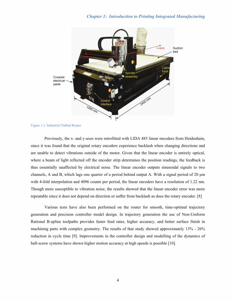
Section 1.2: Experimental Setup and Previous Work
A commercially available Computer Numerical Control (CNC) industrial flatbed router was
donated to the Erkorkmaz Precision Controls Laboratory for the purpose of research (Figure 1.1). The
suction bed area is 1200 mm wide and 2400 mm in length. This suction bed holds the material
stationary, while the spindle moves with respect to the material. A vacuum close to the spindle removes
any chips and dust during cutting. An internal controller communicates to a computer using an RS232
cable and is used when manually jogging the axes with the joystick. Various programs such as SignLab
can be used to program the cutting trajectory. However, this thesis focuses on using MATLAB and a
dSPACE controller environment to develop advanced controllers that override the internal controller
from the router. The dSPACE controller provides high processor power for the Simulink model and
interfaces to the inputs and outputs of the machine.
Three axes allow for gantry movement along parallel ball screws (x-axis), spindle motion along
the gantry (y-axis), and adjustment of spindle height (z-axis), with positioning speeds up to 250 mm/sec
for x and y, and 75 mm/sec for z. All axes are powered by DC motors that can be monitored using
rotary encoders that produce a digital signal. The x-axis has two motors, which are referred to as x-left
and x-right, one for each ball screw. For the x-axes, the motors move with the gantry and the pulley belt
actuates a nut along a stationary ball screw. The y-axis motor drives a pulley belt, which instead rotates
the ball screw, thus translating the nut and components along the axis. Most of the weight on these axes
is supported by the linear guiderails and bearings. x- and y- axes have the same pulley ratio of 4.8 and
the rotary encoders have a resolution of 500 counts/rev plus quadrature interpolation. Having a lead of
25 mm (the linear travel distance per revolution), this corresponds to an encoder resolution of 2.6 μm.
With the same rotary encoder, though a different pulley ratio of 2.4 and a lead of 5 mm, the z-axis
encoder resolution is 1.042 μm.
Chapter 1: Introduction to Printing Integrated Manufacturing
4
Figure 1.1: Industrial Flatbed Router
Previously, the x- and y-axes were retrofitted with LIDA 485 linear encoders from Heidenhain,
since it was found that the original rotary encoders experience backlash when changing directions and
are unable to detect vibrations outside of the motor. Given that the linear encoder is entirely optical,
where a beam of light reflected off the encoder strip determines the position readings, the feedback is
thus essentially unaffected by electrical noise. The linear encoder outputs sinusoidal signals to two
channels, A and B, which lags one quarter of a period behind output A. With a signal period of 20 μm
with 4-fold interpolation and 4096 counts per period, the linear encoders have a resolution of 1.22 nm.
Though more susceptible to vibration noise, the results showed that the linear encoder error was more
repeatable since it does not depend on direction or suffer from backlash as does the rotary encoder. [8]
Various tests have also been performed on the router for smooth, time-optimal trajectory
generation and precision controller model design. In trajectory generation the use of Non-Uniform
Rational B-spline toolpaths provides faster feed rates, higher accuracy, and better surface finish in
machining parts with complex geometry. The results of that study showed approximately 13% - 26%
reduction in cycle time [9]. Improvements in the controller design and modelling of the dynamics of
ball-screw systems have shown higher motion accuracy at high speeds is possible [10].

Chapter 1: Introduction to Printing Integrated Manufacturing
5
Section 1.3: Scope of Thesis
This chapter introduced the concept of printing integrated manufacturing and its advantages and
potential applications. Previous research in the Erkorkmaz Precision Controls Laboratory has improved
both the position tracking control and the optimised trajectory generation for the performance of a low-
grade, CNC router, resulting in the ability to manufacture high-quality, high-accuracy products. The
goals of the research described in this thesis were to integrate an inkjet printing system onto this
existing industrial flat-bed router, modify the controller software design to further improve positioning
accuracy, and demonstrate the ability to print high-quality images at high-speed onto porous substrates
such as paper and medium density fibreboard (MDF).
To understand the process of inkjet printing, Chapter 2 presents a general overview of the
science and terminology surrounding this technology, along with a synopsis of recent developments in
industrial inkjet printing. The methodology, design, and steps taken to integrate the Xaar inkjet printing
system with the CNC router can be found in Chapter 3. Chapter 4 explains how a high-accuracy motion
controller was developed for improved image resolution and speed of the printing and milling
processes. This is followed by Chapter 5, which describes the calibration process and characterisation
of droplet placement accuracy for variations of monochrome, unidirectional, bidirectional, and
multicolour prints. An analysis of printing on different substrate materials can be found in Chapter 6
before the final conclusions and recommendations in Chapter 7.

6
Chapter 2: Literature Review Printing technology has advanced significantly over the past few decades, starting with dot-
matrix printers, moving to the first commercial piezoelectric inkjet printers marketed in the late 1970s,
then the first thermal inkjet printer with improved performance produced in 1984 by Hewlett-Packard,
and most recently, laser printing [11]. Since then home and office printers have become commonplace;
able to print quickly, in wide-format, and in full colour. Printer formats in which the printhead moves
with respect to the substrate or the substrate moves while the printhead remains stationary are both
common. Currently, most printers rely on inkjet or laser printing technology, both of which can be
subdivided further based on their mode of operation. Unlike lithographic methods, both processes are
classified as non-impact printing, which means that no mechanical device comes into contact with the
substrate, and are thus ideal for substrates where contact with the surface would cause damage. In
addition to this advantage, comparative quality, low noise, small size, low cost, and the ability to print
in colour quickly pushed inkjet and laser printing ahead of traditional processes such as impact dot-
matrix printing.
Various methods of inkjet printing are described in Section 2.1. The system selected for
integration with a flatbed router was chosen based on ease of integration, maintenance, cost, and
flexibility for future research. Some of the main terminology and issues in printing and image
generation are discussed in Section 2.2, followed by a more extensive analysis of the fluid mechanics
and composition in Section 2.3. There are many parameters to consider for stable droplet formation,
including fluid and substrate selection, waveform shape and frequency, and maintenance. Section 2.4
will mention some of the companies that have successfully implemented printing integrated systems to
directly print on non-traditional substrates for use in a diversity of industries. Conclusions from the
literature review can be found in Section 2.5.
Chapter 2: Literature Review
7
Section 2.1: Printing Methods
Inkjet printing is defined by the ability to generate a sequence of fluid micro-drops with
predetermined size and precisely controlled trajectories. This technology has been used to deposit a
very wide range of materials, for many different applications, with the only restriction being that the
material must be in liquid form with appropriate rheological properties at the time and location of
printing. There is a broad range of applications for inkjet printing simply due to all the possible fluid to
substrate combinations. This makes it applicable to industries such as print media, MEMS, and
photolithography. Materials which have been printed include metals, ceramics, and artificial polymers,
as well as various biological materials including living cells. An early application for the direct printing
of liquid metal was to form solder droplets on electronic printed circuits. Metallic particles suspended in
a suitable liquid can be printed by inkjet processes, and are used for both structural and electrical
applications. Inkjet printing is typically divided into two specific droplet formation methods known as
continuous inkjet (CIJ), in which individual droplets are diverted from a continuous stream, and drop-
on-demand (DOD), in which droplets are formed only when needed. These two groups can be further
classified based on the mechanism of operation, including acoustic, thermal, and piezoelectric, with
each having its own advantages and disadvantages. [5]
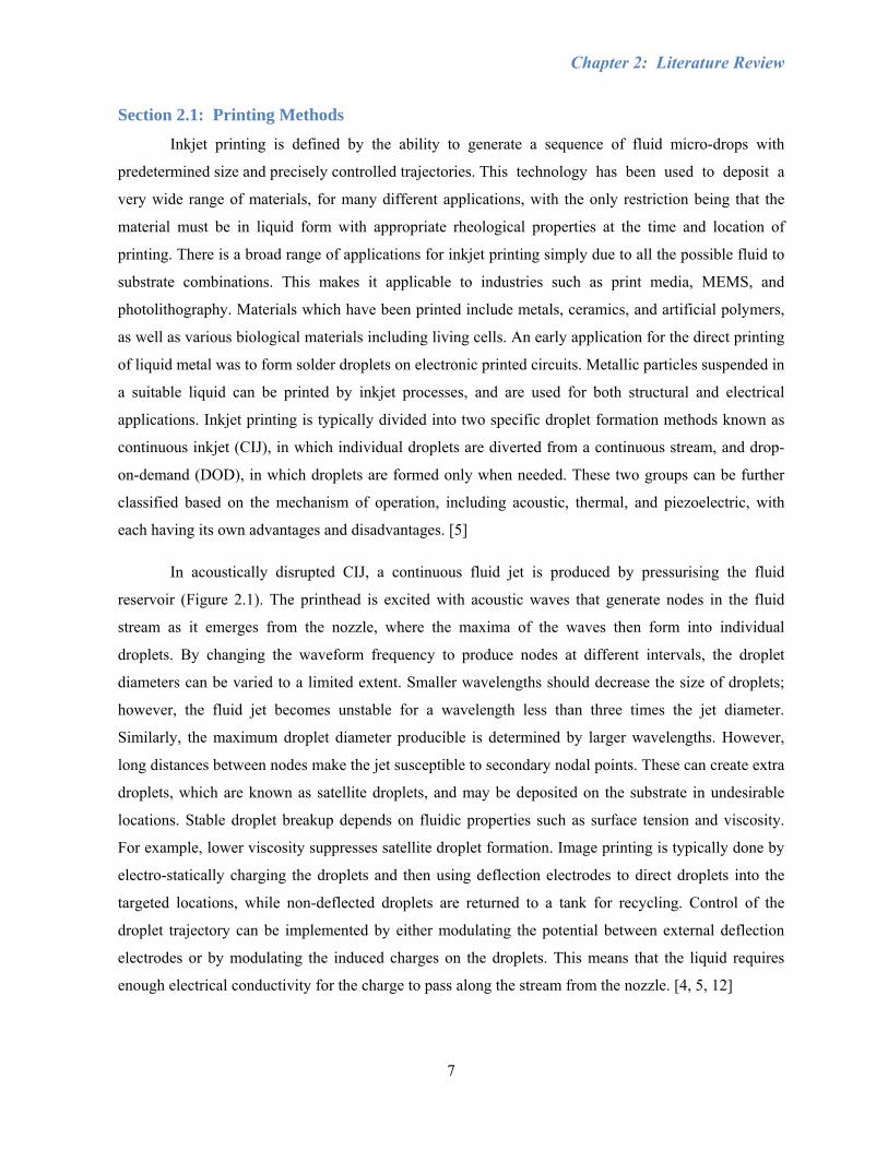
In acoustically disrupted CIJ, a continuous fluid jet is produced by pressurising the fluid
reservoir (Figure 2.1). The printhead is excited with acoustic waves that generate nodes in the fluid
stream as it emerges from the nozzle, where the maxima of the waves then form into individual
droplets. By changing the waveform frequency to produce nodes at different intervals, the droplet
diameters can be varied to a limited extent. Smaller wavelengths should decrease the size of droplets;
however, the fluid jet becomes unstable for a wavelength less than three times the jet diameter.
Similarly, the maximum droplet diameter producible is determined by larger wavelengths. However,
long distances between nodes make the jet susceptible to secondary nodal points. These can create extra
droplets, which are known as satellite droplets, and may be deposited on the substrate in undesirable
locations. Stable droplet breakup depends on fluidic properties such as surface tension and viscosity.
For example, lower viscosity suppresses satellite droplet formation. Image printing is typically done by
electro-statically charging the droplets and then using deflection electrodes to direct droplets into the
targeted locations, while non-deflected droplets are returned to a tank for recycling. Control of the
droplet trajectory can be implemented by either modulating the potential between external deflection
electrodes or by modulating the induced charges on the droplets. This means that the liquid requires
enough electrical conductivity for the charge to pass along the stream from the nozzle. [4, 5, 12]
Chapter 2: Literature Review
8
Figure 2.1: Continuous Inkjet (CIJ) - Ink droplets fall continuously into a tank, while electrical charges are used to deflect select droplets to the desired locations. Courtesy of IOP Publishing Ltd. [12]
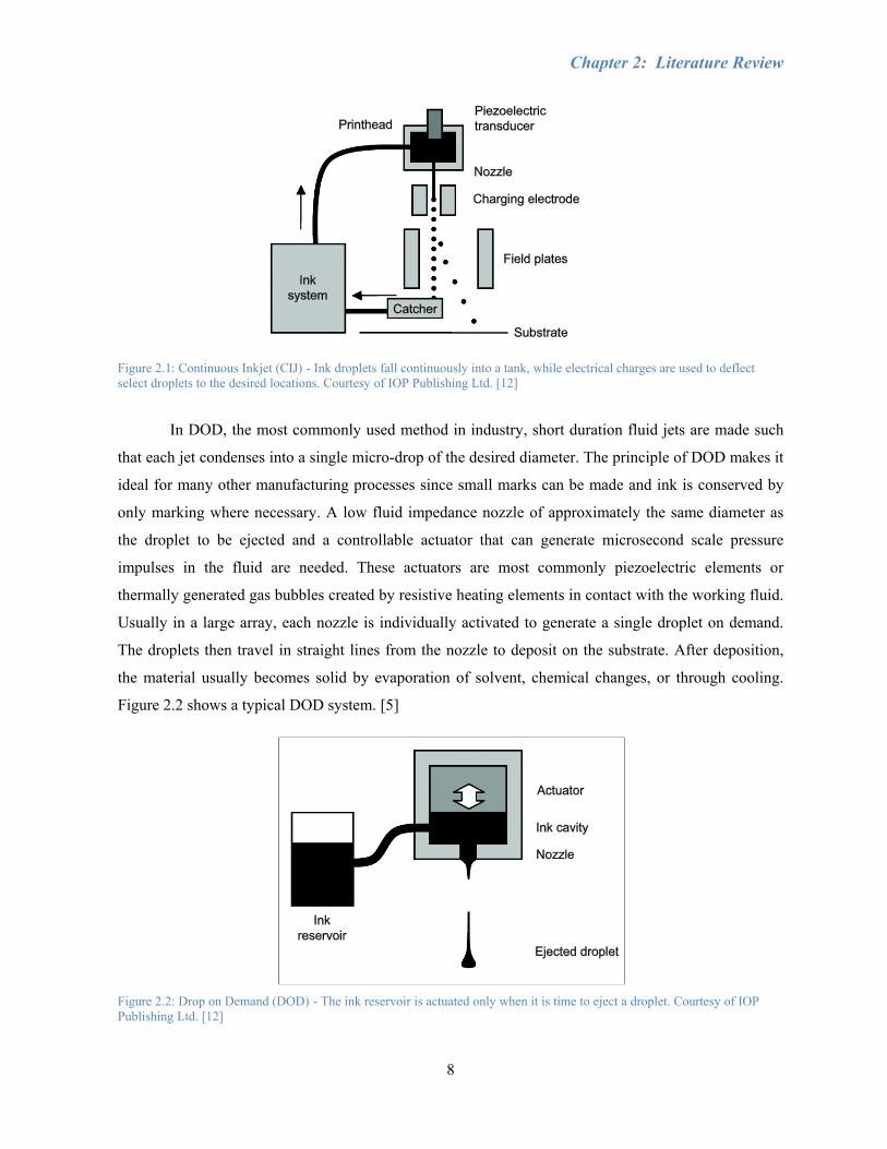
In DOD, the most commonly used method in industry, short duration fluid jets are made such
that each jet condenses into a single micro-drop of the desired diameter. The principle of DOD makes it
ideal for many other manufacturing processes since small marks can be made and ink is conserved by
only marking where necessary. A low fluid impedance nozzle of approximately the same diameter as
the droplet to be ejected and a controllable actuator that can generate microsecond scale pressure
impulses in the fluid are needed. These actuators are most commonly piezoelectric elements or
thermally generated gas bubbles created by resistive heating elements in contact with the working fluid.
Usually in a large array, each nozzle is individually activated to generate a single droplet on demand.
The droplets then travel in straight lines from the nozzle to deposit on the substrate. After deposition,
the material usually becomes solid by evaporation of solvent, chemical changes, or through cooling.
Figure 2.2 shows a typical DOD system. [5]
Figure 2.2: Drop on Demand (DOD) - The ink reservoir is actuated only when it is time to eject a droplet. Courtesy of IOP Publishing Ltd. [12]
Chapter 2: Literature Review
9
One of the main differences between CIJ and DOD methods is the frequency of droplet
generation. CIJ is capable of producing droplets at MHz rates and even its minimum operating range in
the tens to hundreds of kHz is higher than the maximum operating frequencies of DOD. The maximum
frequency in DOD is constrained by the sequential, discrete time steps it takes for fluid ejection and
cavity replenishment. To make up for a lower maximum rate of droplet production, DOD utilises
miniaturisation and massive paralleling of independently operating ejectors into a common functional
unit, suitable for fabrication with well-established integrated circuit processes. Although early CIJ
systems used single or small numbers of nozzles, while DOD is typically operated with tens or
hundreds, both are now capable of handling many hundreds of nozzles and there is significant
convergence between the two technologies. Generally, CIJ systems operate with fluids of lower
viscosity, higher droplet velocity, and tend to require larger quantities of fluid for pumping and
recirculation than DOD. However, certain DOD nozzle arrays also circulate the fluid through the nozzle
manifold to improve reliability. Current trends in research are to increase droplet generation rates in
DOD and develop the ability to generate droplets of variable size by using complex drive waveforms,
which produces a stream of micro-droplets merging into a single, large droplet before contacting the
substrate. Despite its quick droplet generation rates, integrating a system based on CIJ would have the
disadvantage of higher hydraulic complexity and significant maintenance. As well, due to very high
minimum operating fluid volumes and a substantial amount of ink wasted in evaporation, CIJ is
unsuitable for applications in which small quantities of high-value fluids must be micro-dispensed.
While droplet diameters for DOD printing are larger than in CIJ, the advantages of DOD include
flexibility with substrates and deposition materials, relative mechanical simplicity, smaller minimum
fluid operating volumes, lower hardware cost, lower maintenance, and ease of use. [4, 5]
Thermal inkjet, or bubble jet, is a DOD method widely implemented in home and small office
printers by companies such as HP and Canon. Electrical pulses are applied to heating elements in
contact with the fluid near the nozzle. This rapid transient heating of the ink creates a short-lived bubble
of vapour which produces pressure impulses to drive a jet of ink out of the nozzle. With the correct
drive levels, the fluid will form into a single droplet. The bubble then collapses, drawing ink from the
reservoir to refill the cavity, and the process can then be repeated. Thus, no moving part or direct
electrical contact with fluid is needed and this technique is easily integrated into a dense array on an
inkjet printhead with low maintenance. Thermal inkjet relies on high nozzle count and firing frequency
to print at high speeds. Since thermal DOD involves the vaporisation of a small volume of the ink, this
places significant restrictions on materials which can be jetted by this method as the fluid must be
relatively volatile. Although thermal inkjet printheads are known for lower cost, they have a shorter
Chapter 2: Literature Review
10
lifespan in part due to higher operating temperatures causing material stresses. Some other
disadvantages are that they lack flexibility in modifying the rise and fall time of the pressure pulse for
optimising control over the ejected fluid jet and the local chemical reactions that take place during each
vaporisation and cooling cycle, which can change the chemical composition of the fluid over time. [4,
5]
Piezoelectric inkjet is similar to thermal, except that a piezoelectric element is used to change
the internal volume of the ink cavity on the application of an electric field in order to generate pressure
waves, which in turn eject ink from the nozzle and then refill the cavity. This method is more common
in industrial inkjet systems and is used by companies such as Epson. Once the jet emerges from the
nozzle, surface tension causes it to form a main droplet followed by a long globule which may collapse
into one or several smaller satellite droplets. As in CIJ, the surface tension and rheological properties of
the liquid strongly influence the formation of droplets and satellite droplets. Pressure pulse rise and fall
times can be modified to optimise monodisperse droplet production free from satellite droplets and
dynamically alter the diameter of the ejected droplets. Piezoelectric inkjet does not chemically alter the
composition of the fluid like in thermal inkjet, so there is much less restriction on the materials which
can be ejected. Although laser printing is known for higher resolution than inkjet printing, it may also
be limited by the types of deposition material since the deposition material is melted onto the substrate,
whereas inkjet printing can handle various fluids including heat-sensitive biomaterials. Shear-mode
designs utilise piezoelectric elements in which the direction of polarisation of the drive element is
nonparallel to that of the applied electric field. Piezoelectric printheads have low power consumption
and high firing frequency, relying on rapid dry time for its solvent-based inks, which may bleed when
exposed to wet conditions. There are no stresses caused by cycled heating or moving parts, meaning
that the lifespan of the equipment is lengthened. However, the components are often difficult to service,
making it necessary to buy full replacements if they do fail. [4, 5, 13]
Three-dimensional printers use starch or plaster-based powder and a binder to print a part layer
by layer. The printer places a thin layer of powder on a platform and then the binder is applied in areas
where the part is to be printed in order to solidify the powder. The platform is then lowered very
slightly, another thin layer of powder is spread on the platform, and the binder is applied again where
needed. This process repeats until the entire part is printed. The part can then be lifted off the platform
and excess powder brushed away. Waxes and resins can be applied to strengthen the result so that the
3D prototype can be used as part of an engineering design process. [14, 15]
Chapter 2: Literature Review
11
Some systems also use solid or UV curable inks. Solid inks are melted in the printhead and
solidify after they are deposited on the substrate and cool. Solid or UV inks would not require a special
coating since there is some mechanism such as heat or light that cures the ink onto the substrate and
very little spreading and absorption occurs. UV ink cures when exposed to UV light, so solvent
evaporation is not really a factor. It has good adhesion, durability, and chemical and solvent resistance
for a wide variety of semi-porous and non-porous substrates, which includes more exotic materials such
as leather, stone, and wood. This also means no over-laminate is needed to protect the print from rain,
sun exposure, or fingerprints. A UV system has low energy and heat requirements, which is beneficial
for temperature-sensitive substrates. However, UV ink performs poorly under conditions with high
levels of abrasion since UV ink deposits are among the thinnest and erode more quickly. The curing
itself is very fast, within 0.2 seconds depending on the colour of the ink and intensity of the UV light
source. The inks are sensitive to proper cure procedures for adhesion between coatings and proper cure
level for each colour, making it less flexible than other ink systems. As multiple colours can be done in
succession by placing a UV light source between each printhead, care must be taken to avoid over-
curing. If too much radiation is applied, then the next colour may not adhere properly, and the effects
are cumulative as over-cured ink can become brittle and flake off. Naturally, UV inks must be kept in a
light-free environment to prevent unwanted curing. The print has excellent colour value, ranging in
opacity from very transparent to translucent, where high levels of transparency produce a very clean
colour gamut. There are no real opaque UV inks since the UV light must reach all the way through the
ink layer to polymerize the ink. This means UV ink does not print well on dark substrates. UV inkjet
would be even more preferable than piezoelectric for printing on a greater variety of substrates;
however, it has a higher initial hardware cost and would be much more complicated to implement due
to the addition of a curing system and also necessary safety measures for working with UV light. [16,
17]
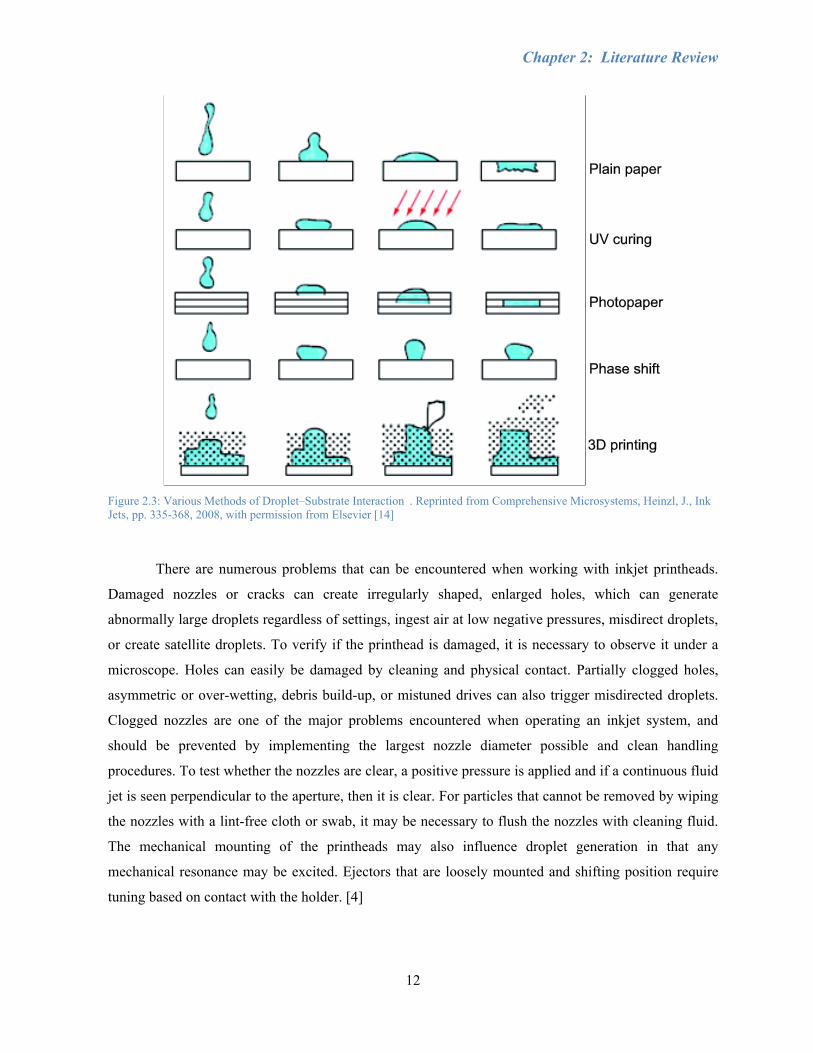
Figure 2.3 shows what happens after depositing a droplet for some of the various printing
methods on different substrates.
Chapter 2: Literature Review
12
Figure 2.3: Various Methods of Droplet–Substrate Interaction . Reprinted from Comprehensive Microsystems, Heinzl, J., Ink Jets, pp. 335-368, 2008, with permission from Elsevier [14]
There are numerous problems that can be encountered when working with inkjet printheads.
Damaged nozzles or cracks can create irregularly shaped, enlarged holes, which can generate
abnormally large droplets regardless of settings, ingest air at low negative pressures, misdirect droplets,
or create satellite droplets. To verify if the printhead is damaged, it is necessary to observe it under a
microscope. Holes can easily be damaged by cleaning and physical contact. Partially clogged holes,
asymmetric or over-wetting, debris build-up, or mistuned drives can also trigger misdirected droplets.
Clogged nozzles are one of the major problems encountered when operating an inkjet system, and
should be prevented by implementing the largest nozzle diameter possible and clean handling
procedures. To test whether the nozzles are clear, a positive pressure is applied and if a continuous fluid
jet is seen perpendicular to the aperture, then it is clear. For particles that cannot be removed by wiping
the nozzles with a lint-free cloth or swab, it may be necessary to flush the nozzles with cleaning fluid.
The mechanical mounting of the printheads may also influence droplet generation in that any
mechanical resonance may be excited. Ejectors that are loosely mounted and shifting position require
tuning based on contact with the holder. [4]
Chapter 2: Literature Review
13
Section 2.2: Printing Resolution and Colour Generation
The overall print quality (resolution and colour) for inkjet printing relies on several variables,
including dot resolution, substrate, ink composition, and deposition method, while the deposition
method and dot resolution will determine how accurately the ink droplets are placed. A swath is one
pass of a printhead, where the width of the swath is determined by the distance from the first nozzle to
the last nozzle and a large image is composed of multiple swaths. Printers create an image by applying
ink or toner to a page in very small dots, where the resolution is typically measured in dots per inch
(DPI). The resolution of the image is based on the separation between successive nozzles. The quality
of the print is based on the size of the coloured dots and how closely they are spaced. Smaller dots that
are more closely packed produce a better quality of output. Higher resolution is thus attainable by
reducing droplet size, which can be controlled by using smaller nozzles. However, the efficiency of the
nozzle varies proportionally with the length of channel to the diameter of nozzle, and thin nozzle
material is difficult to handle. Absorption of the ink depends on both the viscosity of the ink and the
porosity and compatibility of the substrate material. Substrate properties can affect ink application
since, for example, ink tends to spread along fibre grains and into any grooves of the substrate material.
As well, the absorption of ink is often too slow to absorb multiple droplets of ink in the same location
within a short period of time. This results in poor image quality since the ink spreads and colours mix
together. Thus, the substrate should be specially tailored with the ink and vice versa based on variables
such as droplet volume, evaporation rate, penetration rate, coating thickness, and porosity, or else a
special coating is required. [11]
Inks use a subtractive model to generate colour, where the more an element is added, the more
it subtracts from white. The combination of all the colours would theoretically result in black. Since the
result is actually more of a brownish grey and utilises a lot of ink, black ink is often used in addition to
cyan, magenta, and yellow. The hue of the ink is defined as the colour, while saturation is the amount of
colour. Some colour printers place dots of ink very close together to simulate different colours in the
same way that a computer monitor has a triad of colours for a single pixel close together. Other colour
printers use transparent inks and place different colours on top of each other like an artist mixing
colours. Greyscale printers control the size of droplets to vary the colour at each droplet position. The
eye integrates the dots to produce an impression of shade or colour. Image colour will change for
different printers, since each type of output device has a slightly different set of colours that it produces.
Adjustments are necessary to accurately reproduce a colour on a variety of devices, which is sometimes
not possible. [12, 14, 15]

Chapter 2: Literature Review
14
Solvent inks are inexpensive, can be fast drying, and are a good match for semi-porous and
non-porous substrates. Most common solvents are water and oil, which are less hazardous (non-
volatile) than organic solvents and have been found to be well-matched to most porous and semi-porous
substrates. However, solvents will spread along the surface of the substrate unless special coatings are
applied prior to printing. The advantages of using oil-based ink rather than water-based ink are absence
of cockle (rippling) on paper substrates and high light-fastness, which describes how resistant the ink is
to degradation from light sources. [18][19]
If there is no white ink and the ink is somewhat transparent, then the natural colour of the
substrate will show through the ink and deteriorate the image colours. Most printers use CMYK
colours, though there are expanded sets which provide a wider colour gamut or improved tonality. For
example, a new opaque white allows a printer to image directly onto non-white substrates by first
laying down the opaque white coat, then printing the remaining colours on top. The ability to generate
droplets with accuracy is thus crucial to resolution and colour. [11]
Chapter 2: Literature Review
15
Section 2.3: Theory of Droplet Formation in Inkjet Printing
Micro-drops can be generated on demand with diameters ranging from a few microns to tenths
of a millimetre, having well-defined shape and composition, small size, low mass, and the ability to be
ejected with a precise predetermined trajectory. Droplets with identical diameters and ejection speeds
are repeatable to within a fraction of a percent. There are many requirements for reliable droplet
generation. It is not as simple as taking a fluid chamber with a small hole and pressurising it enough for
fluid to emerge from the nozzle or allowing the printhead to leak. If that were the case, then fluid would
accumulate and spread out until a large droplet breaks off when its weight exceeds the surface tension
forces holding it onto the opening, which is not very controllable. Higher, steady pressures would
produce a continuous stream of fluid being pushed out, breaking up into undesirable randomly sized
droplets. Instead, DOD requires special conditions to produce high-speed fluid jets of a certain diameter
and then control the behaviour of the jets precisely enough to allow consistent formation of uniformly
sized droplets. These include the nozzle shape and size, drive pulse shape and frequency, and fluids of a
certain composition. After a droplet is ejected, there are still a significant number of factors to consider,
such as the speed and position of droplets, environmental influence, splashing, and various printhead
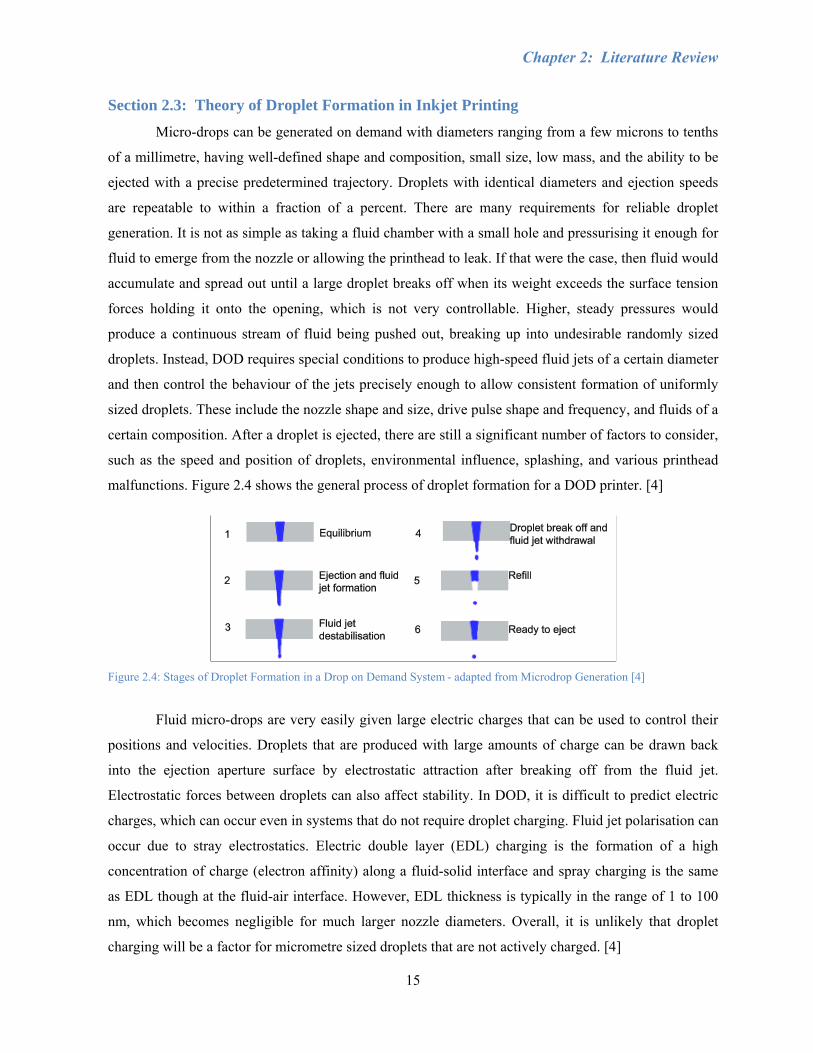
malfunctions. Figure 2.4 shows the general process of droplet formation for a DOD printer. [4]
Figure 2.4: Stages of Droplet Formation in a Drop on Demand System - adapted from Microdrop Generation [4]
Fluid micro-drops are very easily given large electric charges that can be used to control their
positions and velocities. Droplets that are produced with large amounts of charge can be drawn back
into the ejection aperture surface by electrostatic attraction after breaking off from the fluid jet.
Electrostatic forces between droplets can also affect stability. In DOD, it is difficult to predict electric
charges, which can occur even in systems that do not require droplet charging. Fluid jet polarisation can
occur due to stray electrostatics. Electric double layer (EDL) charging is the formation of a high
concentration of charge (electron affinity) along a fluid-solid interface and spray charging is the same
as EDL though at the fluid-air interface. However, EDL thickness is typically in the range of 1 to 100
nm, which becomes negligible for much larger nozzle diameters. Overall, it is unlikely that droplet
charging will be a factor for micrometre sized droplets that are not actively charged. [4]
Chapter 2: Literature Review
16
Highly charged droplets may redeposit onto the ejection aperture surface, forming a layer of
fluid and debris that may impair droplet ejector operation. Also, some fluids have a minimum ejection
rate since the fluid hardens on contact with air or evaporates off volatiles, leaving a locally more
viscous fluid. Both these problems emphasize the need for frequent cleaning of the nozzles and
pressurised purging. As the interval between droplet ejection increases, the amplitude of the required
pulse energy also increases. Printheads may sit nonoperational for unpredictable periods of time. Many
inkjet printers solve this by initiating a print job, which physically wipes the surface of the nozzles over
a pad and into a fluid reservoir prior to depositing droplets onto a target. Another solution is to
continuously actuate the ejector with pulses sufficient enough to only push the fluid jet out of the nozzle
and back without breaking off a free droplet, though this method is not very good for fluids which
harden in air. The ejector can also be capped if it is known in advance when the printheads are not
going to be in use. [4]
Negative internal pressurisation reduces the pulse energy needed to eject droplets and increases
reliability. A high positive internal pressure level will create a forced ejection from the nozzle in the
form of a slow leak, which prevents DOD since a thick, fluid layer covering the nozzle acts as an
obstacle before a free droplet can be formed. This is especially the case when high surface tension
causes the fluid to bind to itself. A thin layer of fluid over the nozzle plate is typically desired, however,
if the meniscus is asymmetric, then droplet direction becomes unpredictable. Some fluids with low
viscosity and surface tension will leak out of the nozzle without negative pressurisation and also form a
thick layer outside of the nozzle. As well, at high droplet generation rates, some fluids leave residue on
the surface near the nozzle hole that builds over time and eventually stops droplet ejection. Negative
internal pressurisation tuned to the fluid and size of the ejection aperture helps by pulling the fluid back
in. Tuning is time dependent, as changing the pulse width will have a settling time where the meniscus
must adjust to the new equilibrium value and can be on the order of minutes. A combination of fluids
and surface coatings for the ejection aperture that minimises this kind of surface wetting should be
chosen. Ideally, the fluid should easily wet the interior of the ejector, yet avoid creating a thick
meniscus on the plate, which can be improved by Teflon coating the outside and leaving the interior
uncoated. A coating inside can raise the energy needed to eject a jet by causing the fluid to fail to wet
the aperture so that it must be driven into contact with the surface of the aperture near the hole before
forming an external jet. Fluids with higher surface tension may need no negative pressurisation at all to
operate as they are not likely to break the meniscus and there is less of a tendency to flow out of the
ejector. [4, 14]
Chapter 2: Literature Review
17
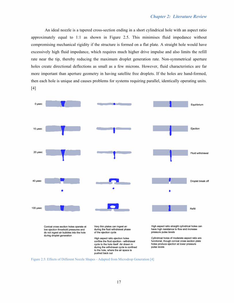
An ideal nozzle is a tapered cross-section ending in a short cylindrical hole with an aspect ratio
approximately equal to 1:1 as shown in Figure 2.5. This minimises fluid impedance without
compromising mechanical rigidity if the structure is formed on a flat plate. A straight hole would have
excessively high fluid impedance, which requires much higher drive impulse and also limits the refill
rate near the tip, thereby reducing the maximum droplet generation rate. Non-symmetrical aperture
holes create directional deflections as small as a few microns. However, fluid characteristics are far
more important than aperture geometry in having satellite free droplets. If the holes are hand-formed,
then each hole is unique and causes problems for systems requiring parallel, identically operating units.
[4]
Figure 2.5: Effects of Different Nozzle Shapes - Adapted from Microdrop Generation [4]
Chapter 2: Literature Review
18
The conditions needed for monodisperse DOD operation are generally tuned by trial and error
until a fluid jet is pushed out at a high enough speed to form a cylindrical column. Tuned standing
waves cause the fluid column to destabilise so that an end node condenses into a separate droplet. The
end node breaks off as the fluid column withdraws back into the ejector as a result of a negative
pressure wave on the interior of the fluid chamber. The pulse shape of the waveform has a wide range
of effects on the tuning for a given fluid and is critical to setting up the system. Excitation of different
vibration modes in the ejected jet and mechanical structure of the droplet ejector is difficult to model, as
it varies for different fluids and even for different fluid-fill levels within the same droplet ejector. Non-
optimal pulse waveforms can cause instability in the form of non-ejection, misdirection, and satellite
droplets. If the drive pulse amplitude is too low, a fluid jet is ejected from the aperture and then drawn
back on the negative pressure cycle of the excitation before the jet has destabilised enough to form
discrete, separate droplets. A large enough amplitude range is needed that will release a single droplet
with each pulse, such that the droplets have uniform size and identical velocities. Higher drive
amplitudes may generate larger droplet size and higher ejection velocity, yet if the amplitude is too
large, then satellite droplets will form. However, the formation of these satellite droplets may not cause
an issue due to its repeatability and common direction of travel of the primary droplet and satellites,
which could allow them to merge back into one droplet. Though, for even larger amplitudes, a chaotic
spray of multi-disperse droplets with random directions of travel is often observed. Overdriving the
printhead with large amplitudes or high frequencies may also cause cavitations in the fluid and air
ingestion into the interior of the droplet generator. Internal air bubbles will act as fluidic shock
absorbers and increase the drive amplitudes required for droplet formation. In addition, during filling,
there would be excessively high negative pressure and high drive pulse amplitudes as the bubbles do
not re-dissolve quickly enough. Minimum amplitude, on the other hand, immediately produces multiple
droplet ejection or random spray. Location and size of satellites can be altered by varying the excitation
waveform by trial and error to optimise the droplet formation. If the pulse rate is too high, then the fluid
builds up at the nozzle, and if the build-up is too low, then evaporation occurs, which changes the
rheological properties of the fluid such that high ejection amplitude is needed. While size of droplets is
determined primarily by the size of the nozzle hole, shorter pulse widths produce smaller droplets,
though they also require higher amplitudes to eject them. Some pulse widths have no amplitude window
at which stable monodisperse droplets are produced. The amount of change in pulse width that can be
tolerated before no longer producing stable droplets is mostly dependent on the fluid used. [4]
Fluids having unfavourable rheological characteristics for stable ejection usually require more
precise control over the drive to piezoelectric elements. Large diameter particles randomly distributed
Chapter 2: Literature Review
19
throughout the working fluid can cause unstable operation by making the break-off of the droplet from
the ejected jet unpredictable since it can act as an instability node. Changes in temperature, back
pressure, fluid level, and humidity (determines meniscus thickness) can also alter the optimal settings
for exciting an ejector to produce monodisperse single droplets on demand. Ejection characteristics can
be enhanced at elevated fluid temperatures, which have a minor effect on surface tension, yet a large
effect on viscosity. Some fluids not stable at room temperature will produce reliable monodisperse
droplets at a slightly elevated temperature since there is a reduction of energy required for ejection. [4]
Of course, it is expected that not all fluids can be jetted from DOD to form monodisperse
droplets. Developing a working fluid for micro-drop ejectors is an extremely difficult process. The
starting materials may consist of combinations of powders, surface coatings, binders, and solvents, all
of which require customised chemical and rheological properties. A long list of material parameters has
to be considered, including viscosity, melting temperature, mean particle size distribution, specific heat,
thermal conductivity, diffusivity, substrate material, and porosity. In a well-engineered micro-drop
ejection fluid the fluid jet and micro-drop formed by each actuation impulse are nearly identical. Thus,
inks contain many different additives to help control the characteristics of the fluid. [4, 5]
Payload is the material put into the micro-drop in order to deposit, react, take a measurement
with, or aerosolise, such as pigments and dyes. Solvents are used to suspend or dissolve the payload.
Humectants prevent drying out or solidification in the ejection cavity. As most low molecular weight
fluids like water and gasoline are Newtonian, viscosity modifiers are used to increase the viscosity of
the fluid in order to extend the period of time that suspended solids will remain mixed and not settled
out. Polymeric fluid elasticity agents (long chain soluble molecules) prevent satellite formation by
suppressing fragmentation of the fluid jet into random-sized spray. Long chain molecules give elasticity
which causes the fluid jet to have a greater tendency to remain in a cohering mass that ultimately pulls
together into a single droplet rather than disintegrating into many smaller separate satellite droplets.
Anti-fungal agents (biocides and preservatives) are added to inks since the aqueous media for many
micro-drop ejection fluids may deteriorate due to growth of microorganisms. Chelating agents bind to
metal ions to prevent formation of scale deposits upon evaporation of fluids near the ejection aperture.
Additives specific for inkjet image printing include penetrants that aid in penetration of ink into fibrous
media such as paper and fabrics. Without penetrants, some inks may bead up on the surface of paper,
suffer smearing, and have excessively long drying time. Mechanical immobilisation of dye pigments,
once deposited as an image, is important for documents that may be frequently handled or stacked and
rubbed against other documents. Thus, fixatives and binders (resins and polymers) are added to increase
smear resistance of printed images. Anticockel additives reduce the tendency for ink, when absorbed
Chapter 2: Literature Review
20
into paper, to wrinkle, curl, or otherwise mechanically distort the final document. Ultraviolet blockers,
free-radical inhibitors, and antioxidants are utilised to protect the image from fading, which is mostly a
result of sunlight exposure. There are three main causes of chemical degradation of dyes and pigments:
exposure to light (particularly UV components), atmospheric oxygen, and chemical free radicals. [4]
Surfactants are added to ejection fluids to alter surface tension for stable droplet ejection. Some
surfactants double as effective dispersants, which aid in the maintaining of solids such as pigment
particles in stable suspension. High shear forces and surfactants are required to break up particle
agglomerations. Surfactants aid in wetting since structurally, the molecules facilitate suspension by
having one portion that binds to the solid particle and another portion that is strongly philic with fluid.
Particles are coated with a surface layer that suppresses van der Waals mediated agglomeration of
particles into larger solids, which would gravitationally settle or jam ejection aperture holes. The
coating must be matched to both the solvent and type of particles to be suspended. Another method of
preventing re-agglomeration includes rotary mixers to generate high shear forces to break up particles.
The method and duration of mixing can make a strong difference in the quality of the final suspension
as poor mixing can result in particles settling within a short time. [4, 5]
Other provisions exist for making suspensions of ground solids able to be ejected from a
nozzle, as there is a difference between stable particle suspension and fluid particle slurry. Small
particles are generally favoured as the suspensions are more stable. The reasons are that the particles do
not sediment and nozzle clogging is avoided. The maximum diameter for a particle that can be stably
suspended depends upon the material. Ink pigments typically have a diameter of 0.1 µm, while inkjet
printer droplets range from 15 to 40 µm. Larger particles will gravitationally settle in a timeframe too
short for most applications. Since the size of the particles approaches the diameter of the ejection
aperture hole, the presence in random locations of large particles unpredictably destabilises the ejected
fluid jet, leading to unreliable droplet formation. Crushing and grinding is ineffective when the particle
diameter is from 10 to 100 µm. Solids subjected to mechanical stress will also fracture along lines of
weakness. The number of such defects decreases as the particles are fractured into smaller sizes. The
force required to fracture a defect-free small particle is far higher than that needed to break it along a
crystal plane dislocation. Re-agglomeration occurs as small, freshly fractured particles with clean
crystal planes that contact each other in the correct manner fuse back together into a single particle. The
necessary diameter that the suspended particles must be reduced to varies with the specific gravity of
the fluid and solids, as well as the viscosity of the fluid. It is difficult to predict the ability of a fluid to
be ejected based on its components alone. In the end, the only way to determine the quality of the inkjet
fluid is to test it. [4]
Chapter 2: Literature Review
21
Section 2.3.1: Kinetics
Micro-drops of different diameters falling in air can be imaged to study the transition between
the dominance of turbulent and laminar flow for drag resistance of objects of different sizes. While the
naked eye can observe droplet diameters as small as 10 μm, micro-drops are usually imaged in an area
backlit against a dark background with a stroboscope [4, 12]. In terms of fluid dynamics, inertia,
viscosity, and surface tension are the dominant forces which control the behaviour of liquid jets and
droplets. A micro-drop is small enough that its associated Reynolds Number causes the forces
associated with viscous flow resistance to motion defined by Stokes Law to be dominant. Reynolds
number is a measure of the ratio of the dynamic pressure drag force to the Stokes viscous drag force on
a given object moving through a fluid media such as air:
ηρDv=Re ( 1 )
where η is the dynamic viscosity of air (182.7x10⁻⁶ g/cm·s at standard temperature and pressure), ρ is
the density of air (0.0011206 g/cm3), v is the velocity with respect to air, and D is the characteristic
diameter, which is usually taken to be the jet or droplet diameter. Weber number We is:
σρ 2DvWe = ( 2 )
Where σ is the surface tension, describes the ratio between kinetic energy and surface energy (between
inertial and surface forces). Sometimes Ohnesorge number Oh is a more useful value to consider, as it
describes the relative importance of viscous and surface forces:
( ) 2121 Re DWeOh ρση== ( 3 )
Stable DOD printing of a fluid may occur only if Oh is between about 0.1 and 1. For Oh greater than 1,
viscous dissipation in the fluid prevents droplet ejection, while for Oh less than 0.1, multiple droplets
form rather than a single well-defined droplet. The ability of a fluid to be ejected thus involves both its
viscosity and also the Ohnesorge number. [5, 12]
The drag force is given by:
2
21 AvCF ddrag ρ= ( 4 )
where Cd is the drag coefficient and A is the frontal area. Stokes Law drag factor dominates over
dynamic pressure drag in determining both terminal velocity in air and the relaxation time constant.
Cunningham’s correction factor, Cc, corrects for atmosphere not being a perfect continuum. Resistance
of air is slightly less than that predicted by Stokes Law by 1/Cc and the error is larger for smaller
droplets. [4]
Chapter 2: Literature Review
22
Terminal velocity is calculated by setting the gravitational force on the droplet equal to that of
the velocity dependent drag forces and keeping in mind the following guidelines:
100 ,
0.1 ,
0.1 , 9.0 10 /
An initial velocity of 1 to 10 m/s is typical for DOD inkjet, about three orders of magnitude faster than
the final velocity of ejected droplets in air. How rapidly the droplet decelerates is critical to determining
the distance between the droplet ejector and the substrate surface. The relaxation time constant, τ, is the
parameter that characterises motion of the fluid droplet that has not come into equilibrium with
externally applied forces. It is a measure of how fast the motion of the droplet comes to steady state
after initial ejection, changes in local air speed, or application of external forces induced by electric or
magnetic fields. There are large differences in impact behaviour of the droplet depending upon how
much the droplet has slowed in air from its initial ejection velocity. Micro-drops with diameters ranging
below 10 microns are difficult to precisely deposit due to perturbing effects of air convection. While the
droplet is moving at high velocity just after ejection it is much less vulnerable to deflection by
convection currents. Operation in totally convection-free air may be impractical, particularly if the
droplet ejector is being continuously moved and repositioned by a robotically controlled motion stage.
Outside of a convection-controlled chamber, the target should be positioned such that the droplet
traverses the distance between the ejector and the target at a high enough velocity that local air currents
do not significantly deflect the droplet. This may be difficult for small droplets since deceleration is
rapid and maximum stable droplet ejection speed tends to be slower the smaller the droplet size. As
mentioned, past a certain drive level, stable droplet production ceases and the droplet ejector starts to
produce satellite droplets and spray. Thus, as large a droplet as possible should be used for any
application requiring accurate positioning in open air. [4]
The extent of the high velocity region of an ejected droplet trajectory can be estimated by
multiplying the relaxation time by the initial ejected speed of the droplet. The relaxation time constant τ
can be calculated as follows, where g is the gravitational acceleration, yh is the horizontal distance
travelled by a horizontally ejected droplet as a function of time, yv is the vertical distance, vhi is the
initial horizontal ejection velocity, and vvi is the initial vertical velocity:
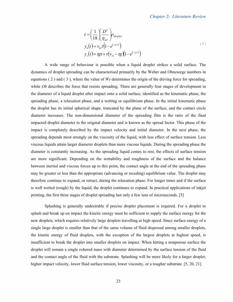
Chapter 2: Literature Review
23
( ) ( )( )( ) ( ) ( )( )τ
τ
τττ
τ
ρη
τ
tviv
thih
dropletair
egvgtty
evty
D
−
−
−−+=
−=
⎟⎟⎠
⎞⎜⎜⎝
⎛⎟⎠⎞
⎜⎝⎛=
1
1
181 2
( 5 )
A wide range of behaviour is possible when a liquid droplet strikes a solid surface. The
dynamics of droplet spreading can be characterised primarily by the Weber and Ohnesorge numbers in
equations ( 2 ) and ( 3 ), where the value of We determines the origin of the driving force for spreading,
while Oh describes the force that resists spreading. There are generally four stages of development in
the diameter of a liquid droplet after impact onto a solid surface, identified as the kinematic phase, the
spreading phase, a relaxation phase, and a wetting or equilibrium phase. In the initial kinematic phase
the droplet has its initial spherical shape, truncated by the plane of the surface, and the contact circle
diameter increases. The non-dimensional diameter of the spreading film is the ratio of the final
impacted droplet diameter to the original diameter and is known as the spread factor. This phase of the
impact is completely described by the impact velocity and initial diameter. In the next phase, the
spreading depends most strongly on the viscosity of the liquid, with less effect of surface tension. Less
viscous liquids attain larger diameter droplets than more viscous liquids. During the spreading phase the
diameter is constantly increasing. As the spreading liquid comes to rest, the effects of surface tension
are more significant. Depending on the wettability and roughness of the surface and the balance
between inertial and viscous forces up to this point, the contact angle at the end of the spreading phase
may be greater or less than the appropriate (advancing or receding) equilibrium value. The droplet may
therefore continue to expand, or retract, during the relaxation phase. For longer times and if the surface
is well wetted (rough) by the liquid, the droplet continues to expand. In practical applications of inkjet
printing, the first three stages of droplet spreading last only a few tens of microseconds. [5]
Splashing is generally undesirable if precise droplet placement is required. For a droplet to
splash and break up on impact the kinetic energy must be sufficient to supply the surface energy for the
new droplets, which requires relatively large droplets travelling at high speed. Since surface energy of a
single large droplet is smaller than that of the same volume of fluid dispersed among smaller droplets,
the kinetic energy of fluid droplets, with the exception of the largest droplets at highest speed, is
insufficient to break the droplet into smaller droplets on impact. When hitting a nonporous surface the
droplet will remain a single cohered mass with diameter determined by the surface tension of the fluid
and the contact angle of the fluid with the substrate. Splashing will be more likely for a larger droplet,
higher impact velocity, lower fluid surface tension, lower viscosity, or a rougher substrate. [5, 20, 21]
Chapter 2: Literature Review
24
Section 2.4: Recent Developments in Industrial Inkjet Printing Applications
Flatbed inkjet systems have been introduced to industry within the past few years. The substrate
can either be placed directly on the flatbed while the printheads move or the substrate can move relative
to the printheads. Most flatbed inkjet systems use ultraviolet-curable inks and the traditional CMYK
colour gamut. Some systems have begun to use opaque white, which allows the ink to be printed on
substrates that are not white by first printing the opaque white coat before the remaining colours. A
final varnishing coat can also be printed after the image. Again, this provides the opportunity to expand
printed products to such industries as signage and furniture. [22]
Various printing component and ink suppliers such as Dimatix, Spectra, Xennia, Xaar,
KonicaMinolta, and Hewlett-Packard recognise the benefits of using their technology to develop
custom printing systems for applications like coding and marking, light-emitting polymers, conductive
fluids, signage, addressing, decor, textiles, wall and floor coverings, and MEMS. There are some
companies like Zünd and Hymmen that have further developed printing technology outside of
traditional applications. It is only a matter of time before direct printing approaches the precision and
repeatability necessary for MEMS fabrication.
Zünd is a company in Switzerland that specialises in flatbed printing and cutting sheet material
for mass-distribution. Four colours (CMYK) and white or six colours (CMYK, light cyan, light
magenta) are available for higher apparent resolution, smoother gradients, and better skin tones. White
ink can be printed either before (under), after (over), or with other colours to achieve all possible optical
effects, while the white density is controllable through software settings. Their systems are versatile,
modular, and allow for straightforward and accurate double-sided printing and edge to edge capabilities
of virtually any media in any size. This includes both uncoated rigid and flexible materials, smooth,
uneven, or perforated surfaces, and boards, sheets, or rolled materials such as plexiglass, wood,
cardboard, glass, metal, polyester, polycarbonate, polystyrene, PVC, perforated plates, fabrics, mesh,
stone, foamboard, wallpaper, canvas, ceramics, leather, cork, aluminum, and vinyl. Applications
include indoor/outdoor signage, advertising and decorations, posters, exhibition and stage graphics,
banners, flags, billboards, vehicle graphics, furniture, architecture, and showrooms. The UV ink system
is environmentally friendly and free from any solvents (VOC), outdoor durable with excellent colour
vibrancy, and shows good adhesion to a wide variety of materials, economical in use, and has minimal
startup time. Print materials can be up to 40 mm thick, 2150 mm wide, and have unlimited length.
Maximum resolution is 360 DPI at a print speed of 38 m2/h (typically 7 – 20 m2/h). Ink consumption is
about 80 m2/L. Zünd is capable of plotting, cutting, milling, and engraving at a maximum 10 mm depth
for soft materials and 2 mm for hard materials, with a foam cutter at 1-1000 mm/sec speed, +/- 0.02 mm

Chapter 2: Literature Review
25
repeatability, 30 mm material clearance, max feed speed of 250 mm/sec, feed accuracy of +/-0.1 mm;
and 0.005 mm measuring system resolution. A vacuum table is used for material fixation. [23]
Hymmen is another company that provides surface finishing of board (MDF, particle, etc.) or
roll material and the production of decorative and technical laminates. They develop, manufacture, and
distribute machinery and lines such as their DecoPrint coating line (DPR). The decor printing machine
is a fast and economic alternative to laminating of decor paper, for the printing of wood and fantasy
decors onto veneer and wooden work pieces. A water-based (environmentally friendly) ink, water-
based varnishes, and UV build-up are used. The process typically consists of several steps, beginning
with a dry base coat, followed by base colour, print, corundum, varnish for smoothness and hardness,
counter-coating, and ending with lacquering. The final hardness layer creates a pore structure. Hymmen
is the first company to successfully produce printed laminate flooring, using Xaar 1001 printheads for
their Jupiter line. However, there is still a long way to go based on easy handling, adequate production
performance, and high surface quality. Decorative finishes are done in film or melamine resin
impregnated paper to MDF or particleboard. The finishes are similar to natural wood in appearance and
can be superior in terms of durability and damage resistance. Line speeds range from 167 to 2000
mm/sec and include roll press for boards, foils, and glue. DPR flooring is up to 20% quieter than
traditional laminate flooring and a uniform product structure prevents stresses in the floor. This flooring
also remains more stable during temperature changes (i.e. heating in winter). [24, 25, 26]
The Hymmen GmbH digital printing machine (DGP) relies on very sensitive deposition control
(dosing) of the ink output leading to an equally precise printing image. It consists of a single-pass
printing station, an ink supply, a conveyor system, and a drying module. This setup relies on the
material to be printed being positioned on a transport slide that passes under fixed printing heads,
allowing a substrate to be printed across the double width of the printing zone in two steps. Small
differences in the dot size provide subtle grey shades, which in conjunction with low ink consumption
keep operating costs low. Xaar 1001 printheads feature a resolution of 360 DPI (binary vs. greyscale
nearly triples optical resolution), low sensitivity to contamination of printing station, minimum risk of
blockage of ink nozzles, and insensitivity to vibrations and crashes. Hymmen discusses a gravure
process which contains inaccuracies due to tolerances in the wood panel, different pressures of the
application rollers, differences in velocity between printing machines, and process and machinery
related tolerances. [1, 24, 25, 26]
Chapter 2: Literature Review
26
Section 2.5: Conclusions
The basic principles of printing have been investigated thoroughly by many, such as the
characteristics of droplet formation, colour, and motion control. However, the theory of droplet
generation is still not exact and the specific concept of printing integrated manufacturing is still a
relatively new area of research that has not been widely explored. Given the proprietary and
commercial nature of the printing research field, availability of literature references and publicly
available documents describing the engineering design of existing systems is minimal. It is often
necessary to experience much of the already established knowledge of printing firsthand in order to
understand the complications of the process. Though similar technology exists, the focus of this
research was to improve the results of current technology and also the machining of materials such as
wood and metal. Little research has been done specifically on the combination of printing and
manufacturing, likely due to the problems with noise and vibration, which could affect printhead firing
and accuracy. There are numerous tolerance areas between the work piece and apparatus where
inaccuracy could be introduced, such as work piece surface finish or straightness, printhead calibration,
and machine structure. Dust from the air or particles from the cutting process could easily clog the
nozzles and prevent the flow of ink, requiring constant cleaning and maintenance. Also, the amount of
material research would be quite extensive as different substrates require different inks and methods of
surface preparation.
This chapter has presented background information on inkjet printing and materials deposition
technologies, introduced the terms and concepts involved, and also reviewed recent developments in
both printing mechanisms and applications. As discussed, there are a number of challenges in inkjet
printing. Greater understanding of the processes and quantitative parameter relationships need to be
developed for modelling more accurate and reliable processes such as droplet formation, droplet
impact, and drying or curing. This would allow for a more methodical approach rather than relying on
trial and error testing, and could potentially lead to further miniaturisation for MEMS and
nanotechnology applications. More research should be done to establish resolution, absorption, and
colour interactions for different substrates and deposition materials, including the composition of the
materials themselves. Faster deposition rates would encourage the use of inkjet deposition for mass-
production and commercialisation. Laser-based direct printing technologies are slow to commercialise
due to high hardware cost and limitations in deposition materials and substrate dimensions.
A piezoelectric inkjet system, which is used in the work described in this thesis, is well-suited
for integration with the existing flatbed router due to its simpler mechanisms, ease of use, and potential
for future applications requiring more sensitive deposition fluids compared to CIJ, thermal inkjet, and

Chapter 2: Literature Review
27
laser methods. However, the minimum droplet size may limit its use for MEMS and nanotechnology
development. There are several things that should be noted for the implementation of an inkjet printing
system. For example, they are susceptible to dust and vibration, which are prevalent in manufacturing
environments. Maintenance of the printheads includes daily wiping of the nozzle plates and occasional
flushing to ensure no debris is blocking the nozzles and to remove excess ink for accurate droplet
formation and positioning. Also, significant research and testing may need to be done to obtain
satisfactory image results on wood substrates, most likely by using a white pre-coat. A UV system will
provide better results on different substrates, though it has a higher initial hardware cost and added
system complexity. It may be possible to predict the positioning error of the droplets, though the
calculations would be quite complicated. Convection may be a factor depending on how quickly a
droplet is ejected from the printhead and the distance between the nozzle and the substrate.
Flatbed inkjet systems similar to the work described in this thesis have been recently developed
in industry. Zünd manufactures a flatbed system with specifications similar to that of the router used in
this research, and can thus provide an industrial comparison in terms of tracking control. Their router is
capable of a maximum feed of 250 mm/sec with a feed accuracy of +/- 0.1 mm and 0.005 mm encoder
resolution. Hymmen has also successfully printed laminate flooring using MDF, Xaar 1001 printheads,
and water-based ink.
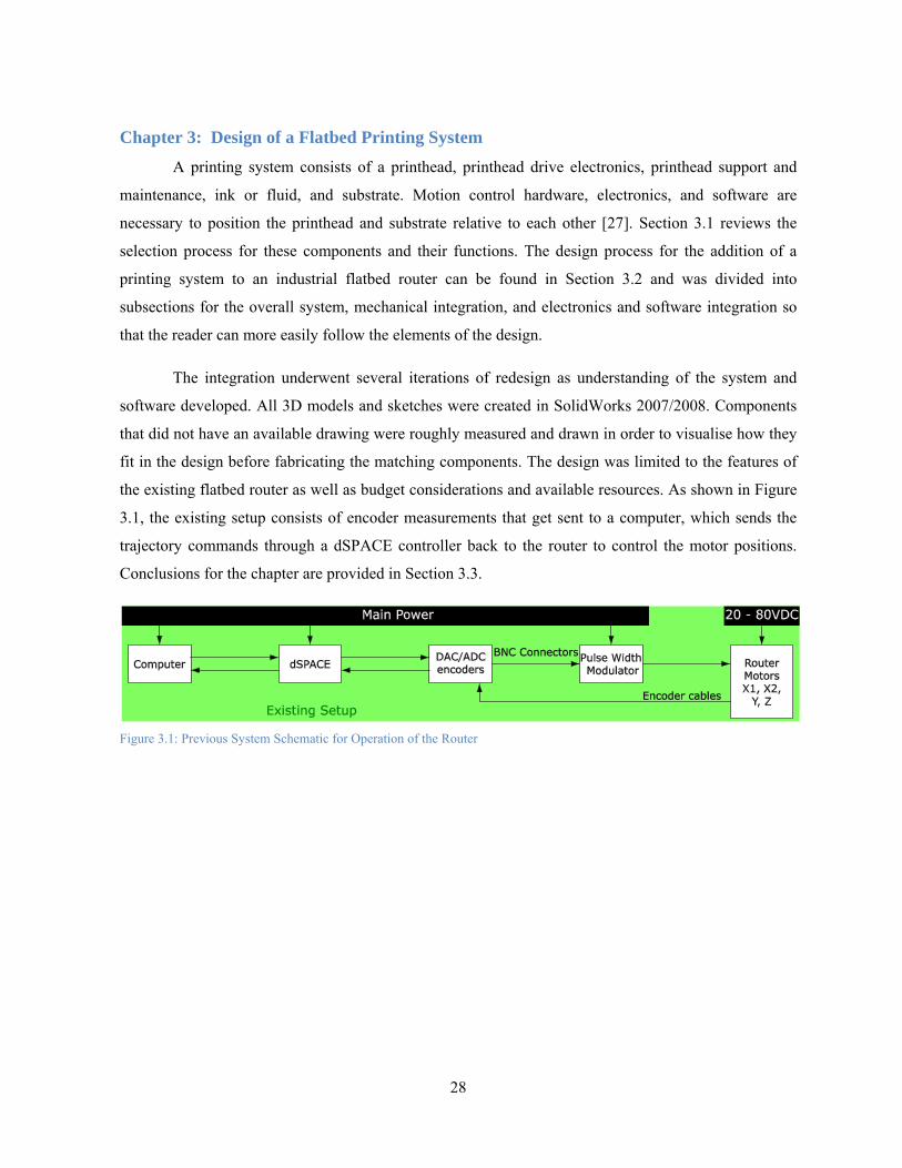
28
Chapter 3: Design of a Flatbed Printing System A printing system consists of a printhead, printhead drive electronics, printhead support and
maintenance, ink or fluid, and substrate. Motion control hardware, electronics, and software are
necessary to position the printhead and substrate relative to each other [27]. Section 3.1 reviews the
selection process for these components and their functions. The design process for the addition of a
printing system to an industrial flatbed router can be found in Section 3.2 and was divided into
subsections for the overall system, mechanical integration, and electronics and software integration so
that the reader can more easily follow the elements of the design.
The integration underwent several iterations of redesign as understanding of the system and
software developed. All 3D models and sketches were created in SolidWorks 2007/2008. Components
that did not have an available drawing were roughly measured and drawn in order to visualise how they
fit in the design before fabricating the matching components. The design was limited to the features of
the existing flatbed router as well as budget considerations and available resources. As shown in Figure
3.1, the existing setup consists of encoder measurements that get sent to a computer, which sends the
trajectory commands through a dSPACE controller back to the router to control the motor positions.
Conclusions for the chapter are provided in Section 3.3.
Figure 3.1: Previous System Schematic for Operation of the Router

Chapter 3: Design of a Flatbed Printing System
29
Section 3.1: Printing Component Selection
As digital printing is application specific, no manufacturer has all the components necessary to
develop a complete printing system. Printhead suppliers provide limited electronics and software
together with generic application notes and technical support based on their experience [27]. Thus, the
main concern was finding a system as complete as possible that could be readily assembled onto the
existing machine at a reasonable cost (less than $30 000). Most companies like Xerox and Canon only
offer completely assembled printers for certain applications. Other companies such as Fujifilm Dimatix,
Global Inkjet Systems, Accu Automation, and Xaar sell customisable kits, which are suitable for
integration with the router. However, Fujifilm Dimatix does not supply systems to small end-users or
researchers and Global Inkjet Systems does not provide all the necessary components. It was also found
that the system from Accu Automation was much more expensive than the Xaar system, despite the
convenience of the company location in Cambridge, and offered more high-end functionality then
required in the initial prototype. Thus, Xaar was chosen as the supplier for the printing system.
Xaar provides printing kits that can be readily assembled onto existing machines to fit the
applications of different companies. They design various printheads and their corresponding peripherals
and supply inks depending on the application. It was decided that the Xaar 126 printheads would be the
best choice to start learning about the printing process due to their simple design, light weight, low cost,
ease of integration, and compatibility with a variety of different ink types such as oil-based and UV-
curable to allow for future modifications. Oil-based ink was selected for its absorption properties with
wood, non-toxicity, and low maintenance. The Xaar 126 printheads are binary, which means that the
printhead nozzles fire in two modes: on or off. As a result, the image generation and droplet formation
are also slightly easier to understand than higher resolution greyscale printheads, whose droplet sizes
can be variable. However, the drawbacks of its simple design are limited resolution, difficulty in
alignment, susceptibility to dust and damage, and limited colour. Specifications for the Xaar 126
printheads can be found in Appendix A.
The kit came with all the components necessary for printing, except the actuation system and
position encoder, which are chosen by the system designer. It included four pumps, four filters, four
header tanks, four manual valves, a supply of cyan, magenta, yellow, and black ink bottles, various luer
fittings, clear Teflon tubing, an ink supply controller (ISC), a printhead controller (XUSB), USB 2.0
cable, XUSB power supply, software for the XUSB and ISC, head personality card (HPC unit), two
power cables, two link cables, four printhead mounting plates (not used), eight adjustment screws, four
ribbon cables, and four printheads. Items that were requisitioned elsewhere include two USB 2.0
repeaters, two RS232 extension cables, extra Teflon tubing (only available in imperial measurements),
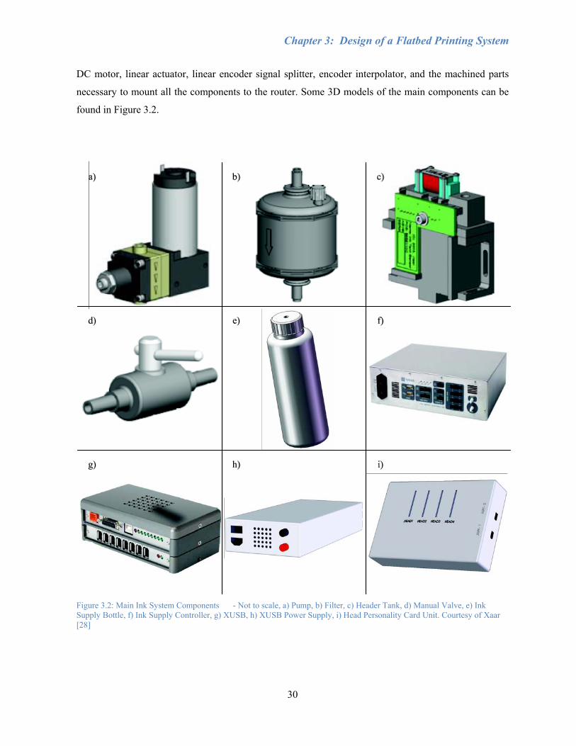
Chapter 3: Design of a Flatbed Printing System
30
DC motor, linear actuator, linear encoder signal splitter, encoder interpolator, and the machined parts
necessary to mount all the components to the router. Some 3D models of the main components can be
found in Figure 3.2.
Figure 3.2: Main Ink System Components - Not to scale, a) Pump, b) Filter, c) Header Tank, d) Manual Valve, e) Ink Supply Bottle, f) Ink Supply Controller, g) XUSB, h) XUSB Power Supply, i) Head Personality Card Unit. Courtesy of Xaar [28]
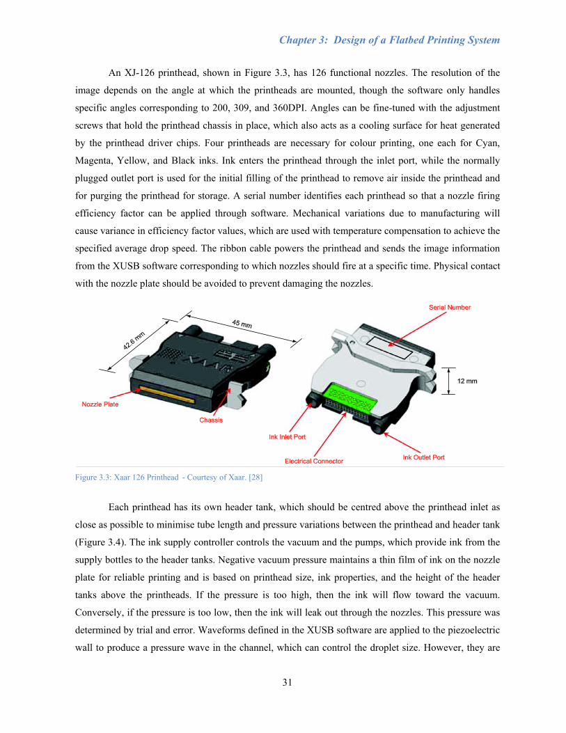
Chapter 3: Design of a Flatbed Printing System
31
An XJ-126 printhead, shown in Figure 3.3, has 126 functional nozzles. The resolution of the
image depends on the angle at which the printheads are mounted, though the software only handles
specific angles corresponding to 200, 309, and 360DPI. Angles can be fine-tuned with the adjustment
screws that hold the printhead chassis in place, which also acts as a cooling surface for heat generated
by the printhead driver chips. Four printheads are necessary for colour printing, one each for Cyan,
Magenta, Yellow, and Black inks. Ink enters the printhead through the inlet port, while the normally
plugged outlet port is used for the initial filling of the printhead to remove air inside the printhead and
for purging the printhead for storage. A serial number identifies each printhead so that a nozzle firing
efficiency factor can be applied through software. Mechanical variations due to manufacturing will
cause variance in efficiency factor values, which are used with temperature compensation to achieve the
specified average drop speed. The ribbon cable powers the printhead and sends the image information
from the XUSB software corresponding to which nozzles should fire at a specific time. Physical contact
with the nozzle plate should be avoided to prevent damaging the nozzles.
Figure 3.3: Xaar 126 Printhead - Courtesy of Xaar. [28]
Each printhead has its own header tank, which should be centred above the printhead inlet as
close as possible to minimise tube length and pressure variations between the printhead and header tank
(Figure 3.4). The ink supply controller controls the vacuum and the pumps, which provide ink from the
supply bottles to the header tanks. Negative vacuum pressure maintains a thin film of ink on the nozzle
plate for reliable printing and is based on printhead size, ink properties, and the height of the header
tanks above the printheads. If the pressure is too high, then the ink will flow toward the vacuum.
Conversely, if the pressure is too low, then the ink will leak out through the nozzles. This pressure was
determined by trial and error. Waveforms defined in the XUSB software are applied to the piezoelectric
wall to produce a pressure wave in the channel, which can control the droplet size. However, they are
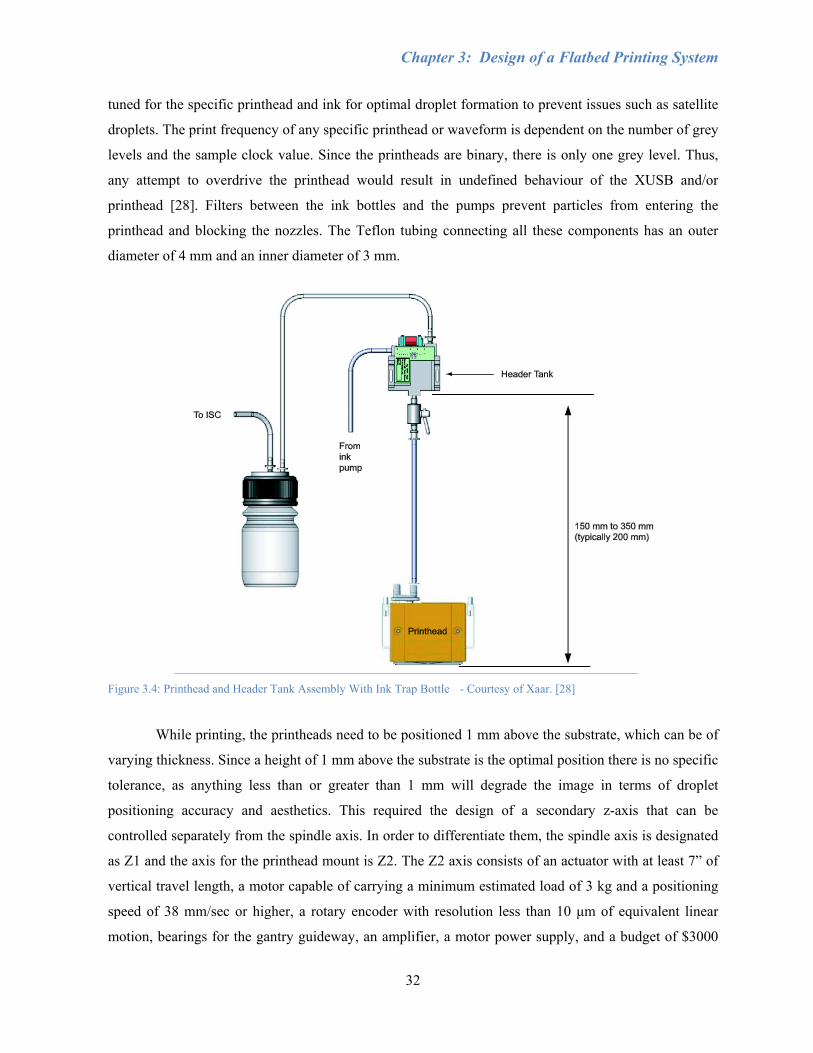
Chapter 3: Design of a Flatbed Printing System
32
tuned for the specific printhead and ink for optimal droplet formation to prevent issues such as satellite
droplets. The print frequency of any specific printhead or waveform is dependent on the number of grey
levels and the sample clock value. Since the printheads are binary, there is only one grey level. Thus,
any attempt to overdrive the printhead would result in undefined behaviour of the XUSB and/or
printhead [28]. Filters between the ink bottles and the pumps prevent particles from entering the
printhead and blocking the nozzles. The Teflon tubing connecting all these components has an outer
diameter of 4 mm and an inner diameter of 3 mm.
Figure 3.4: Printhead and Header Tank Assembly With Ink Trap Bottle - Courtesy of Xaar. [28]
While printing, the printheads need to be positioned 1 mm above the substrate, which can be of
varying thickness. Since a height of 1 mm above the substrate is the optimal position there is no specific
tolerance, as anything less than or greater than 1 mm will degrade the image in terms of droplet
positioning accuracy and aesthetics. This required the design of a secondary z-axis that can be
controlled separately from the spindle axis. In order to differentiate them, the spindle axis is designated
as Z1 and the axis for the printhead mount is Z2. The Z2 axis consists of an actuator with at least 7” of
vertical travel length, a motor capable of carrying a minimum estimated load of 3 kg and a positioning
speed of 38 mm/sec or higher, a rotary encoder with resolution less than 10 μm of equivalent linear
motion, bearings for the gantry guideway, an amplifier, a motor power supply, and a budget of $3000

Chapter 3: Design of a Flatbed Printing System
33
CAD [29]. It was also desirable to minimise the width of the drive system, since its addition to the
gantry will reduce work area where both the printheads and spindle can reach. The spindle can no
longer travel to the far left of the gantry, the printhead cannot access the far right, and the distance
between printheads also limits the working area since the Black printhead will not be able to reach the
same position as the Cyan printhead.
A ball-screw drive was chosen for its high efficiency, speed, duty cycle, tool life, accuracy, and
repeatability, as well as constant backlash. A LinTech Series 130 linear stage was selected, having a
precision grade ball-screw of 0.625” diameter with 0.2” (5.08 mm) lead and a maximum travel length
of 8”, along with a DC servo motor and rotary encoder. The negatives of this design are that it is easily
back-driven and the price is higher for an increase in speed compared to other options such as a belt and
pulley. It was indeed found that earlier self-locking calculations for the DC servo motor based on the
weight of 3 kg and safety factor of 5 were correct. Based on the SolidWorks model, the total weight of
the assembly is approximately 5 kg. However, when the motor is powered off the ball-screw is easily
back-driven due to the weight on the assembly, which causes an issue when developing the homing
routine in Section 4.4. The electrical motor brake was ineffective in holding the ball-screw in place for
situations where the router is turned on and no control signals are being sent to the motor. The rotary
encoder with quadrature is capable of 4000 counts per revolution. There is no pulley system in the Z2
axis, so the motor directly controls the ball-screw. Thus, given the lead of the ball-screw, the resolution
of the encoder is 5.08 mm/rev divided by 4000 counts/rev, which is 1.27 μm. [29]

Chapter 3: Design of a Flatbed Printing System
34
Section 3.2: System Integration
Figure 3.5 shows the overall system schematic for retrofitting the router with printing capability
using the components discussed in Section 3.1. While each area can be loosely separated into controls,
fluid, software, electrical, and mechanical assemblies, establishing communication between
components and conversion of signal formats is important. The XUSB receives the linear encoder
position from the y-axis to determine the print frequency of droplets, and also controls which printheads
should be firing based on information from the computer. The ISC monitors the pressure readings from
the header tanks to ensure that the correct vacuum pressure is constantly applied.
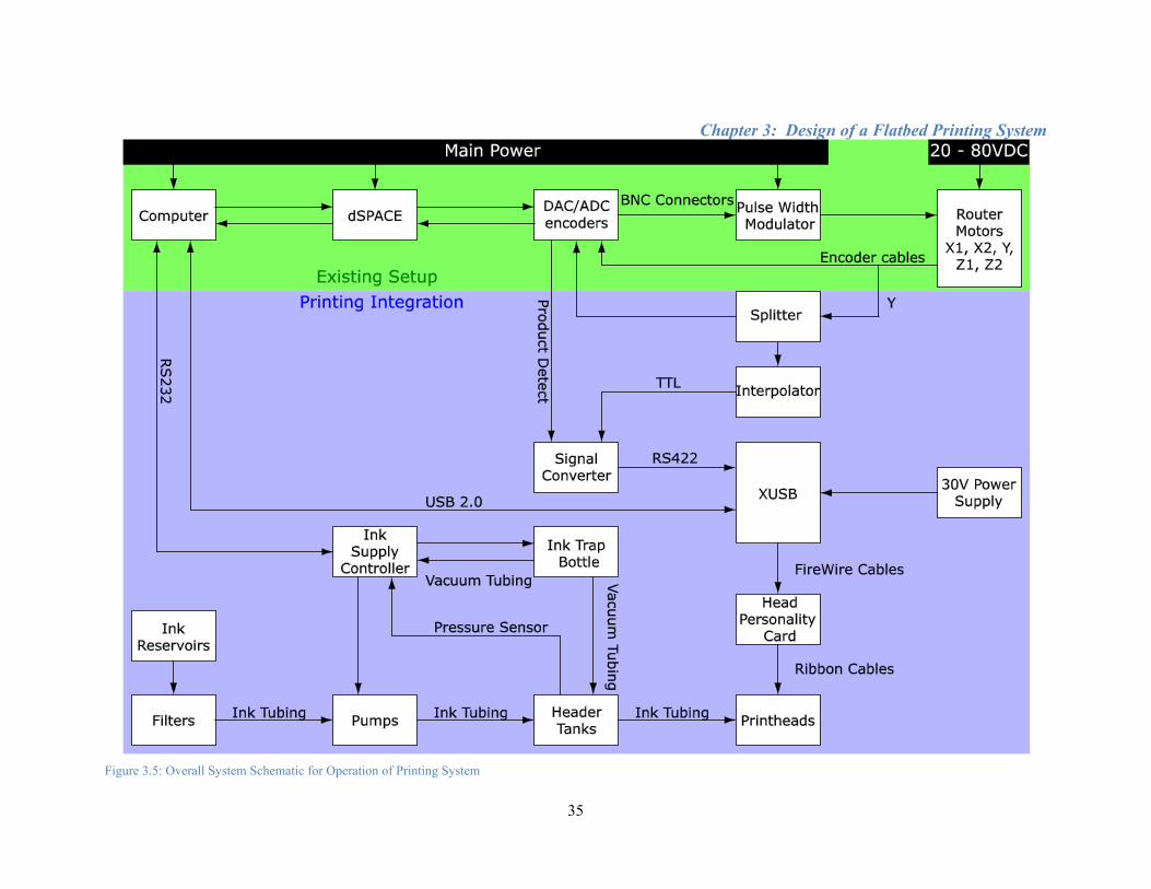
Chapter 3: Design of a Flatbed Printing System
35
Figure 3.5: Overall System Schematic for Operation of Printing System
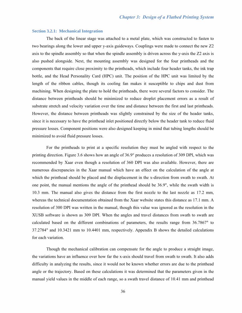
Chapter 3: Design of a Flatbed Printing System
36
Section 3.2.1: Mechanical Integration
The back of the linear stage was attached to a metal plate, which was constructed to fasten to
two bearings along the lower and upper y-axis guideways. Couplings were made to connect the new Z2
axis to the spindle assembly so that when the spindle assembly is driven across the y-axis the Z2 axis is
also pushed alongside. Next, the mounting assembly was designed for the four printheads and the
components that require close proximity to the printheads, which include four header tanks, the ink trap
bottle, and the Head Personality Card (HPC) unit. The position of the HPC unit was limited by the
length of the ribbon cables, though its cooling fan makes it susceptible to chips and dust from
machining. When designing the plate to hold the printheads, there were several factors to consider. The
distance between printheads should be minimized to reduce droplet placement errors as a result of
substrate stretch and velocity variation over the time and distance between the first and last printheads.
However, the distance between printheads was slightly constrained by the size of the header tanks,
since it is necessary to have the printhead inlet positioned directly below the header tank to reduce fluid
pressure losses. Component positions were also designed keeping in mind that tubing lengths should be
minimized to avoid fluid pressure losses.
For the printheads to print at a specific resolution they must be angled with respect to the
printing direction. Figure 3.6 shows how an angle of 36.9° produces a resolution of 309 DPI, which was
recommended by Xaar even though a resolution of 360 DPI was also available. However, there are
numerous discrepancies in the Xaar manual which have an effect on the calculation of the angle at
which the printhead should be placed and the displacement in the x-direction from swath to swath. At
one point, the manual mentions the angle of the printhead should be 36.9°, while the swath width is
10.3 mm. The manual also gives the distance from the first nozzle to the last nozzle as 17.2 mm,
whereas the technical documentation obtained from the Xaar website states this distance as 17.1 mm. A
resolution of 300 DPI was written in the manual, though this value was ignored as the resolution in the
XUSB software is shown as 309 DPI. When the angles and travel distances from swath to swath are
calculated based on the different combinations of parameters, the results range from 36.7867° to
37.2784° and 10.3421 mm to 10.4401 mm, respectively. Appendix B shows the detailed calculations
for each variation.
Though the mechanical calibration can compensate for the angle to produce a straight image,
the variations have an influence over how far the x-axis should travel from swath to swath. It also adds
difficulty in analyzing the results, since it would not be known whether errors are due to the printhead
angle or the trajectory. Based on these calculations it was determined that the parameters given in the
manual yield values in the middle of each range, so a swath travel distance of 10.41 mm and printhead
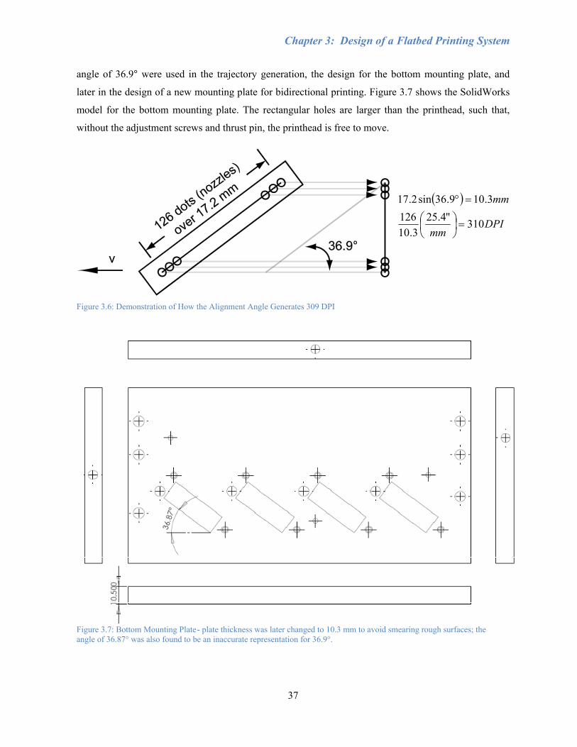
Chapter 3: Design of a Flatbed Printing System
37
angle of 36.9° were used in the trajectory generation, the design for the bottom mounting plate, and
later in the design of a new mounting plate for bidirectional printing. Figure 3.7 shows the SolidWorks
model for the bottom mounting plate. The rectangular holes are larger than the printhead, such that,
without the adjustment screws and thrust pin, the printhead is free to move.
( )
DPImm
mm
310"4.253.10
1263.109.36sin2.17
=⎟⎠⎞
⎜⎝⎛
=°
Figure 3.6: Demonstration of How the Alignment Angle Generates 309 DPI
Figure 3.7: Bottom Mounting Plate - plate thickness was later changed to 10.3 mm to avoid smearing rough surfaces; the angle of 36.87° was also found to be an inaccurate representation for 36.9°.
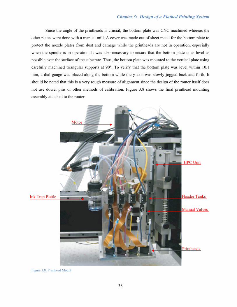
Chapter 3: Design of a Flatbed Printing System
38
Since the angle of the printheads is crucial, the bottom plate was CNC machined whereas the
other plates were done with a manual mill. A cover was made out of sheet metal for the bottom plate to
protect the nozzle plates from dust and damage while the printheads are not in operation, especially
when the spindle is in operation. It was also necessary to ensure that the bottom plate is as level as
possible over the surface of the substrate. Thus, the bottom plate was mounted to the vertical plate using
carefully machined triangular supports at 90°. To verify that the bottom plate was level within ±0.1
mm, a dial gauge was placed along the bottom while the y-axis was slowly jogged back and forth. It
should be noted that this is a very rough measure of alignment since the design of the router itself does
not use dowel pins or other methods of calibration. Figure 3.8 shows the final printhead mounting
assembly attached to the router.
Figure 3.8: Printhead Mount
Motor
Ink Trap Bottle
HPC Unit
Header Tanks
Manual Valves
Printheads

Chapter 3: Design of a Flatbed Printing System
39
Positioning of components such as the ISC and XUSB were limited due to the lengths of the
cables and tubing, which were fed through the existing cable tracks. Thus, it was also necessary for the
XUSB to move along with the gantry. The XUSB was assembled to the right side of the gantry, while
two USB repeaters were used to extend the 5.0 m connection between the XUSB and the computer. The
cables from the XUSB to its power supply were extended so that the power supply could be placed
stationary underneath the cable track on the right side of the router. To minimise tubing length, the ink
supply bottles, pumps, and filters were attached to the back of the gantry; symmetrically to avoid
putting an uneven distribution of weight on the gantry, which could affect positioning accuracy. It was
still necessary to obtain extra Teflon tubing of 1/8” ID and 5/32” OD. Two RS232 extension cables
were used to connect the ISC, located at the lower left-hand side of the router, to the computer, at a
distance greater than the original 10 ft cable. An extension was also made for the cables between the
header tanks and the ISC. Since the length of the vacuum tubing that needed to reach from the ISC to
the ink trap bottle was greater than the 4 m of tubing supplied by Xaar, though less than the 10 m
maximum length, clear PVC tubing of 1/8” ID and 1/4” OD was obtained. Teflon tubing for reduced
friction and wettability was not necessary as the vacuum tubing should only transport air. The power
supply for the Z2 motor was placed inside the front panel of the router and the amplifier was set on top
of the spindle motor housing. Close-ups of the assemblies are found in Figure 3.9 and the final
integrated system is shown in Figure 3.10.
In addition to the physical integration with the router, there are a number of steps that must be
carried out for the general maintenance of the printing system. Before starting to print, the printhead
nozzle plates need to be gently wiped clean of dust and excess ink with a lint-free swab or wipe. As an
extra precaution, the printheads should be purged before wiping, which is a pressure applied to the ink
so that the ink flows freely and is activated through software. However, purging was often found to be
unnecessary unless the printheads have been inactive for one day or longer. Wiping should be done in
one direction only along the nozzles, swabs should not be reused, and extra care should be taken to
ensure that the colours do not mix from one printhead to another, as it is difficult to remove the mixed
colours. If a nozzle appears to be blocked by a particle during print, which cannot be wiped away, then
a purge should be done. Soaking a swab in cleaning solution before wiping the printhead, or as a last
resort, flushing the entire printhead with cleaning solution may be necessary. Otherwise, it is likely that
the nozzle may have been damaged and the printhead must be replaced.
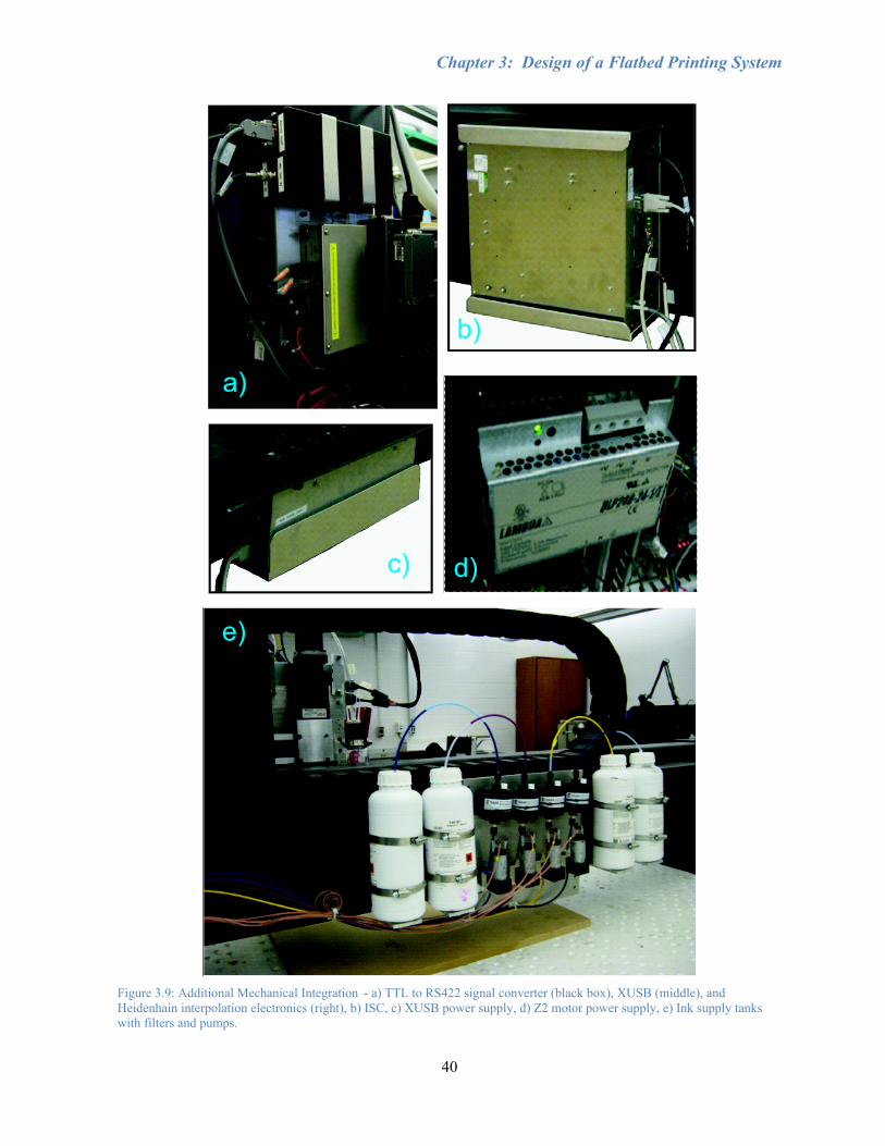
Chapter 3: Design of a Flatbed Printing System
40
Figure 3.9: Additional Mechanical Integration - a) TTL to RS422 signal converter (black box), XUSB (middle), and Heidenhain interpolation electronics (right), b) ISC, c) XUSB power supply, d) Z2 motor power supply, e) Ink supply tanks with filters and pumps.
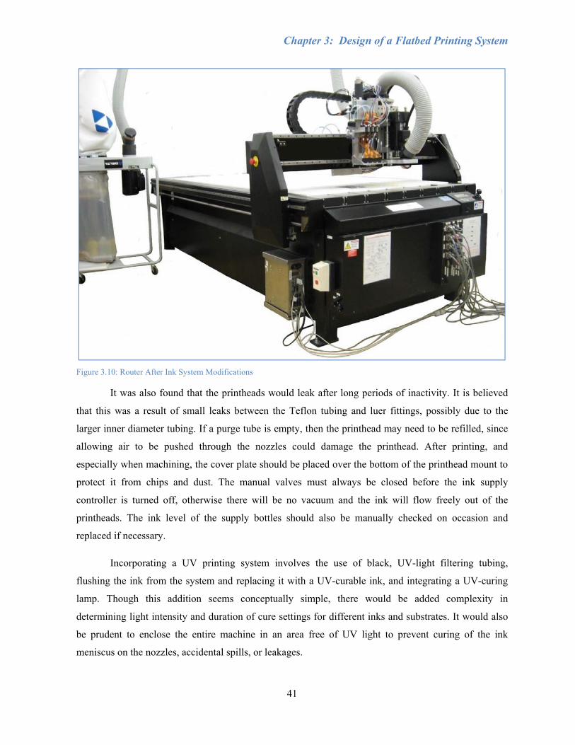
Chapter 3: Design of a Flatbed Printing System
41
Figure 3.10: Router After Ink System Modifications
It was also found that the printheads would leak after long periods of inactivity. It is believed
that this was a result of small leaks between the Teflon tubing and luer fittings, possibly due to the
larger inner diameter tubing. If a purge tube is empty, then the printhead may need to be refilled, since
allowing air to be pushed through the nozzles could damage the printhead. After printing, and
especially when machining, the cover plate should be placed over the bottom of the printhead mount to
protect it from chips and dust. The manual valves must always be closed before the ink supply
controller is turned off, otherwise there will be no vacuum and the ink will flow freely out of the
printheads. The ink level of the supply bottles should also be manually checked on occasion and
replaced if necessary.
Incorporating a UV printing system involves the use of black, UV-light filtering tubing,
flushing the ink from the system and replacing it with a UV-curable ink, and integrating a UV-curing
lamp. Though this addition seems conceptually simple, there would be added complexity in
determining light intensity and duration of cure settings for different inks and substrates. It would also
be prudent to enclose the entire machine in an area free of UV light to prevent curing of the ink
meniscus on the nozzles, accidental spills, or leakages.
Chapter 3: Design of a Flatbed Printing System
42
Section 3.2.2: Electronics and Software Integration
The XUSB requires an encoder to determine the firing frequency of the printheads based on
their position. A linear encoder was used since it provides a much higher resolution and accuracy than
rotary encoder readings. Since it was also desirable to use the linear encoder for controller feedback, a
splitter was made to feed one of the linear encoder signals to the dSPACE and the other to the XUSB.
Originally, an interpolator was made to convert the y-axis linear encoder sinusoidal signal into TTL
signals that the XUSB can read, as well as passing along the PD signal. However, it was thought that
the makeshift converter added error to the analog signals and thus a splitter with an additional 2-fold
increase in resolution was purchased from Heidenhain, along with an interpolator to increase the
resolution of the signal sent to the XUSB by 10-fold. With quadrature encoding as well, the XUSB
would then see an encoder resolution of 0.25 µm. [30]
The Xaar 126 printheads are binary, meaning that the nozzles can only be turned on or off and
one pixel of an image represents one droplet from a single nozzle. However, most computer-generated
images and real photos are made in greyscale, where the droplet size of the ink would need to be
controlled. Thus, greyscale images must be converted to binary (bitmap) images of 309 DPI, which
generally means a decrease in image resolution and quality. Diffusion dithering was used to convert the
images, and although there may be other methods that would result in better image quality, they were
not investigated here [31, 32]. The binary nature of the printheads also means that more bleeding will
occur in dark images since the droplet size cannot be controlled. In printing, the absence of ink is
considered white and the combination of all colours is black. In order to reduce bleeding, the colour
levels are adjusted to preserve the lighter areas of the image, while making darker areas appear lighter.
Thus, darker images will need to be lightened more in a graphics editor than lighter images (Photoshop
was used for this thesis work). Since each printhead represents one of the C, M, Y, and K colours, the
image must also be separated into the four images corresponding to each colour. In the XUSB software,
the image swaths need to be angled according to the angle of the printheads, otherwise the image will
be slanted. Figures and actual order of steps from the image conversion process can be found in
Appendix C, along with the operation of the printing system.
MATLAB software is used to program the print trajectory and controller and is discussed in
further detail in Chapter 4. A Product Detect (PD) signal is essential to notify the XUSB when to start
each swath of print, which should be at precisely the exact same position along the y-axis. It is
developed alongside the trajectory and is a single, short pulse that lasts at least 2 µsec on rising edge
detection, sent to the XUSB once the y-axis motion acceleration has stopped. If the pulse is too long
(i.e. longer than what it would take to print one swath of the image), then the next swath will continue

Chapter 3: Design of a Flatbed Printing System
43
to print beside the previous swath. Likewise, if the pulse is too short, then the print will not start. PD
signals that are not given at the precise location will result in jagged images due to swath misalignment.
In bidirectional printing, a single PD (1PD) method can be used, which relies on the XUSB to
determine where to start the reverse print, or a two PD method (2PD) can be used, which is dependent
on the trajectory to generate a PD for both the forward and reverse swath. Section 4.4 will show how
the PD signal behaves corresponding to both unidirectional and bidirectional trajectories (the PD signal
the XUSB actually sees will be inverted). A separate cable for the PD signal was sent to a converter in
order to change the PD signal into an RS422 signal that is readable by the XUSB hardware. The
MATLAB program should be manually operated in conjunction with the XUSB software. Currently the
print area is limited by the dSPACE memory in which large trajectories will cause an error. It is
believed that if the recorded values are removed and since the trajectory from swath to swath is highly
repetitive, then a repeating Simulink block instead of a large trajectory matrix could be used to reduce
the amount of memory utilised.
Chapter 3: Design of a Flatbed Printing System
44
Section 3.3: Conclusions
This chapter has presented the integration of printing capability onto a flatbed router to
combine printing and machining into one system. The Xaar 126 printing system was chosen for its
simple design, low cost, ease of integration, and potential for future research by using different inks.
The disadvantages of this system are limited resolution and colour, difficulty in alignment, and
vulnerability to dust and damage. The printhead operation is binary and no greyscale is possible.
Nevertheless, the Xaar 126 printing system was deemed suitable for developing the first proof of
concept prototype. Daily maintenance is necessary, which includes purging and wiping excess ink and
particles from the nozzles.
Following the selection of printing technology components, the mechanical, electrical, and
software integration issues were discussed. Some of the shortcomings of the design are the reduction of
useable table area for both cutting and printing, the secondary z-axis motor being susceptible to back-
driving due to the amount of weight from the printhead mount, the substrate being limited to flat
surfaces, and limited trajectory size with the current controller implementation. For future studies, the
motor for the secondary z-axis should be resized, the substrate surface should be level, and the work
area could be enlarged by minimising the mechanical assembly of the spindle and printhead mount and
by reducing memory usage in the dSPACE controller. Nonetheless, the proposed design is useful as a
prototype for investigating new printing integrated manufacturing technologies, in particular for
furniture, wood products, and signage industries.
UV printing capability can also be achieved by upgrading the tubing to black, UV filtering
tubing, flushing the ink from the system and replacing it with a UV-curable ink, and integrating a UV-
curing lamp. Print quality would also be improved with better printheads, such as the Xaar 1001, which
feature easier calibration, greyscale droplet size variation, and lower maintenance due to a self-cleaning
through-flow system that reduces nozzle blockage. Since this project was the pilot study, the focus has
been limited to oil-based inks, which are relatively easier to work with than other fluids. In the
following chapters, implementation and characterisation of the proposed printing system will be
discussed.
45
Chapter 4: Servo System Design
Positioning accuracy is one of the most crucial requirements in developing a printing system,
evident in three main areas: individual droplet positioning, swath-to-swath displacement, and start and
end position alignment. First, printhead motion must follow the commanded trajectory with precision
for the droplets within each swath to fall in their correct locations. Droplets that are too close together
may result in dot merging or bleeding, leading to reduced image sharpness, while droplets that are too
far apart may result in voids or distortions that can also diminish image features (particularly for solid
lines). Next, each swath must be printed directly below the previous swath to prevent visible gaps or
overlapping lines across the image in the y-direction (longitudinal). The ideal swath-to-swath distance
travelled along the x-axis is equivalent to the width of the swath plus the distance between two
successive dots. Finally, the starting (home) and ending positions of each swath must be aligned in the
same location along the y-axis every time; otherwise, the image may have jagged edges or entire swaths
appear shifted horizontally, creating a discontinuous image.
The flaws produced by not correctly achieving any one of these positioning elements are easily
detectable by the human eye. The common keys to each issue are accurate positioning control and
smooth trajectory generation. Unsmooth motion, shock, or vibration could affect the image, appearing
as light and dark bands caused by pressure fluctuations and stitching errors [28]. Droplet positioning
accuracy is also extremely important for future applications in areas such as MEMS fabrication, where
features may require nanometre-scale accuracy. Similarly, the key elements of positioning accuracy
translate to the milling process, consequently leading to rough or distorted surfaces from machining if
they are not achieved adequately. In order to engrave features out of a printed image or cut out the
printed image from a larger work piece, good positioning accuracy is needed to align the shape of the
cut with the printed image.
Both printing and milling processes require a combination of physical adjustment (hardware)
and controller tuning (software). With respect to physical modification to reduce environmental noise,
design changes to the system could be made, such as stiffening the machine by strengthening couplings
and frames and using shorter or larger diameter ball-screw shafts. This would increase the system
spring constant, thereby raising the resonant frequency. Thus, bandwidth could also be increased,
allowing the servo system to be more stable at higher frequencies. As physical adjustments can be
costly, time-consuming, or difficult to assess, they are not covered in this research. The goal in this
chapter is to improve the accuracy of an existing, commercially available machine using control theory.

Chapter 4: Servo System Design
46
The following sections describe the steps taken in order to achieve accurate motion control of
the printheads. Section 4.1 discusses the implementation of a Sliding Mode Controller (SMC) used for
the x-axes. Swath-to-swath alignment is mainly controlled by the SMC. The motion controller was
developed in computational programming software, MATLAB, along with its modelling software,
Simulink. Section 4.2 explains the process used to accurately identify the natural resonance of the
system in order to develop a loop-shaping controller presented in Section 4.3 for improved motion
tracking in the y-axis, which is the main mechanism in determining the positioning accuracy of droplets
along a swath. Frequency response functions (FRFs) and sensitivity plots are used to evaluate the
stability and bandwidth of the servo system. Section 4.4 provides the trajectory generation methods
used to maintain smooth motion, as well as a homing routine for the secondary z-axis. As mentioned in
Section 3.2.2, the Product Detect (PD) signal indicates when to start printing based on the position
trajectory. This is followed by the conclusions in Section 4.5.
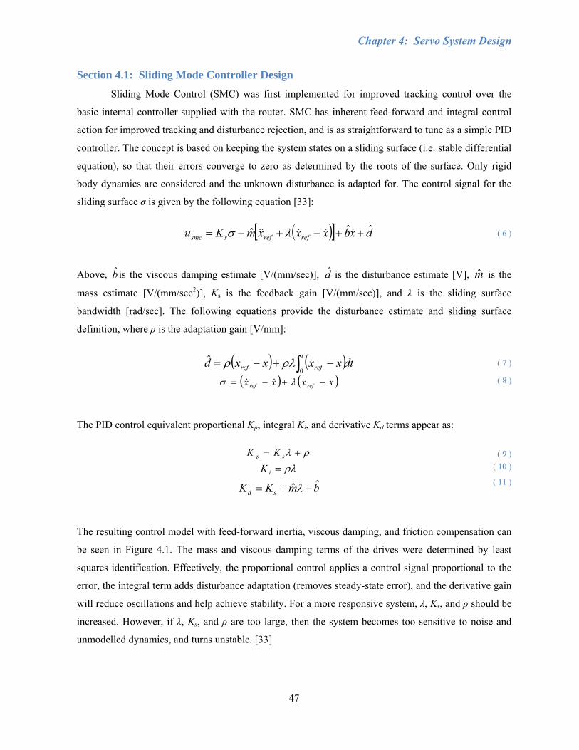
Chapter 4: Servo System Design
47
Section 4.1: Sliding Mode Controller Design
Sliding Mode Control (SMC) was first implemented for improved tracking control over the
basic internal controller supplied with the router. SMC has inherent feed-forward and integral control
action for improved tracking and disturbance rejection, and is as straightforward to tune as a simple PID
controller. The concept is based on keeping the system states on a sliding surface (i.e. stable differential
equation), so that their errors converge to zero as determined by the roots of the surface. Only rigid
body dynamics are considered and the unknown disturbance is adapted for. The control signal for the
sliding surface σ is given by the following equation [33]:
( )[ ] dxbxxxmKu refrefssmcˆˆˆ ++−++= &&&&& λσ ( 6 )
Above, b̂ is the viscous damping estimate [V/(mm/sec)], d̂ is the disturbance estimate [V], m̂ is the
mass estimate [V/(mm/sec2)], Ks is the feedback gain [V/(mm/sec)], and λ is the sliding surface
bandwidth [rad/sec]. The following equations provide the disturbance estimate and sliding surface
definition, where ρ is the adaptation gain [V/mm]:
( ) ( )dtxxxxdt
refref ∫ −+−=0
ˆ ρλρ ( 7 )
( ) ( )xxxx refref −+−= λσ && ( 8 )
The PID control equivalent proportional Kp, integral Ki, and derivative Kd terms appear as:
ρλ += sp KK ( 9 )
ρλ=iK ( 10 )
bmKK sdˆˆ −+= λ
( 11 )
The resulting control model with feed-forward inertia, viscous damping, and friction compensation can
be seen in Figure 4.1. The mass and viscous damping terms of the drives were determined by least
squares identification. Effectively, the proportional control applies a control signal proportional to the
error, the integral term adds disturbance adaptation (removes steady-state error), and the derivative gain
will reduce oscillations and help achieve stability. For a more responsive system, λ, Ks, and ρ should be
increased. However, if λ, Ks, and ρ are too large, then the system becomes too sensitive to noise and
unmodelled dynamics, and turns unstable. [33]
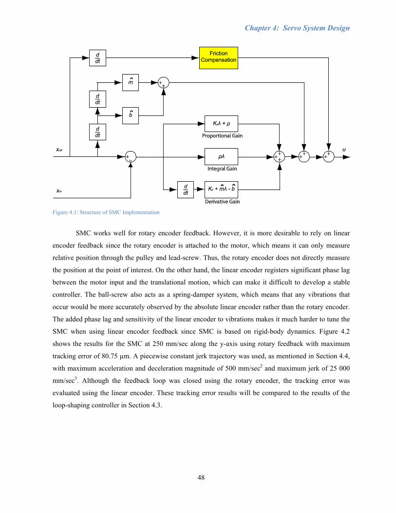
Chapter 4: Servo System Design
48
Figure 4.1: Structure of SMC Implementation
SMC works well for rotary encoder feedback. However, it is more desirable to rely on linear
encoder feedback since the rotary encoder is attached to the motor, which means it can only measure
relative position through the pulley and lead-screw. Thus, the rotary encoder does not directly measure
the position at the point of interest. On the other hand, the linear encoder registers significant phase lag
between the motor input and the translational motion, which can make it difficult to develop a stable
controller. The ball-screw also acts as a spring-damper system, which means that any vibrations that
occur would be more accurately observed by the absolute linear encoder rather than the rotary encoder.
The added phase lag and sensitivity of the linear encoder to vibrations makes it much harder to tune the
SMC when using linear encoder feedback since SMC is based on rigid-body dynamics. Figure 4.2
shows the results for the SMC at 250 mm/sec along the y-axis using rotary feedback with maximum
tracking error of 80.75 µm. A piecewise constant jerk trajectory was used, as mentioned in Section 4.4,
with maximum acceleration and deceleration magnitude of 500 mm/sec2 and maximum jerk of 25 000
mm/sec3. Although the feedback loop was closed using the rotary encoder, the tracking error was
evaluated using the linear encoder. These tracking error results will be compared to the results of the
loop-shaping controller in Section 4.3.
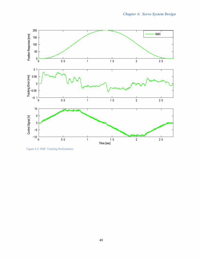
Chapter 4: Servo System Design
49
Figure 4.2: SMC Tracking Performance
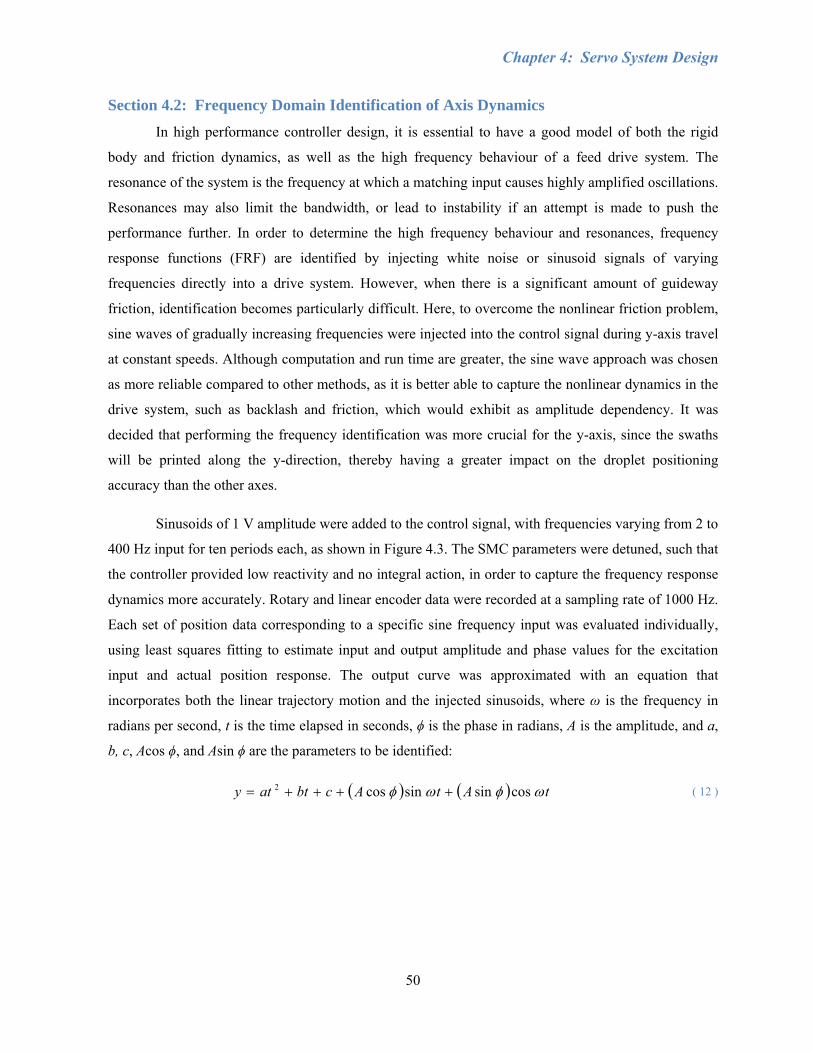
Chapter 4: Servo System Design
50
Section 4.2: Frequency Domain Identification of Axis Dynamics
In high performance controller design, it is essential to have a good model of both the rigid
body and friction dynamics, as well as the high frequency behaviour of a feed drive system. The
resonance of the system is the frequency at which a matching input causes highly amplified oscillations.
Resonances may also limit the bandwidth, or lead to instability if an attempt is made to push the
performance further. In order to determine the high frequency behaviour and resonances, frequency
response functions (FRF) are identified by injecting white noise or sinusoid signals of varying
frequencies directly into a drive system. However, when there is a significant amount of guideway
friction, identification becomes particularly difficult. Here, to overcome the nonlinear friction problem,
sine waves of gradually increasing frequencies were injected into the control signal during y-axis travel
at constant speeds. Although computation and run time are greater, the sine wave approach was chosen
as more reliable compared to other methods, as it is better able to capture the nonlinear dynamics in the
drive system, such as backlash and friction, which would exhibit as amplitude dependency. It was
decided that performing the frequency identification was more crucial for the y-axis, since the swaths
will be printed along the y-direction, thereby having a greater impact on the droplet positioning
accuracy than the other axes.
Sinusoids of 1 V amplitude were added to the control signal, with frequencies varying from 2 to
400 Hz input for ten periods each, as shown in Figure 4.3. The SMC parameters were detuned, such that
the controller provided low reactivity and no integral action, in order to capture the frequency response
dynamics more accurately. Rotary and linear encoder data were recorded at a sampling rate of 1000 Hz.
Each set of position data corresponding to a specific sine frequency input was evaluated individually,
using least squares fitting to estimate input and output amplitude and phase values for the excitation
input and actual position response. The output curve was approximated with an equation that
incorporates both the linear trajectory motion and the injected sinusoids, where ω is the frequency in
radians per second, t is the time elapsed in seconds, ϕ is the phase in radians, A is the amplitude, and a,
b, c, Acos ϕ, and Asin ϕ are the parameters to be identified:
( ) ( ) tAtAcbtaty ωφωφ cossinsincos2 ++++= ( 12 )
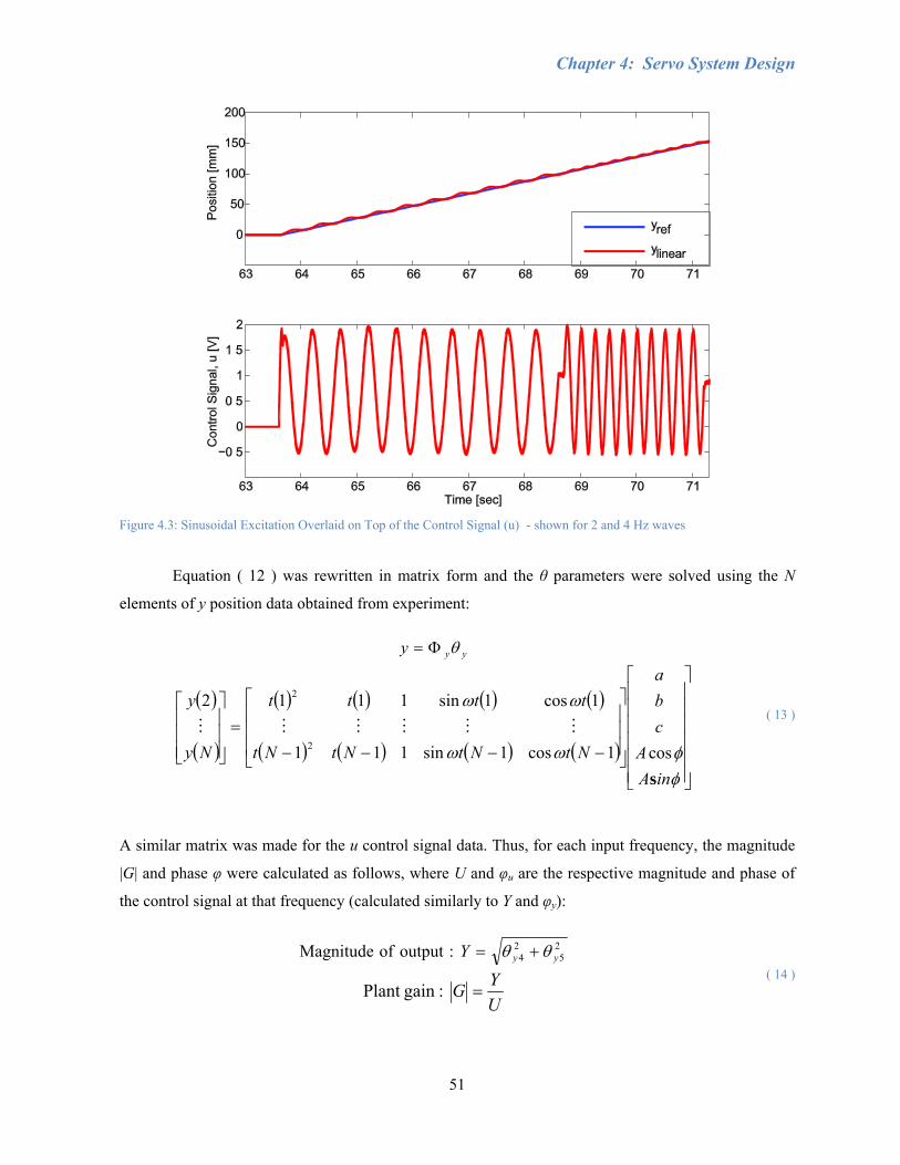
Chapter 4: Servo System Design
51
Figure 4.3: Sinusoidal Excitation Overlaid on Top of the Control Signal (u) - shown for 2 and 4 Hz waves
Equation ( 12 ) was rewritten in matrix form and the θ parameters were solved using the N
elements of y position data obtained from experiment:
yyy θΦ=
( )
( )
( ) ( ) ( ) ( )
( ) ( ) ( ) ( )⎥⎥⎥⎥⎥⎥
⎦
⎤
⎢⎢⎢⎢⎢⎢
⎣
⎡
⎥⎥⎥
⎦
⎤
⎢⎢⎢
⎣
⎡
−−−−=
⎥⎥⎥
⎦
⎤
⎢⎢⎢
⎣
⎡
φφωω
ωω
inAA
cba
NtNtNtNt
tttt
Ny
y
scos1cos1sin111
1cos1sin1112
2
2
MMMMMM ( 13 )
A similar matrix was made for the u control signal data. Thus, for each input frequency, the magnitude
|G| and phase φ were calculated as follows, where U and φu are the respective magnitude and phase of
the control signal at that frequency (calculated similarly to Y and φy):
25
24 :output of Magnitude yyY θθ +=
UYG = :gainPlant
( 14 )
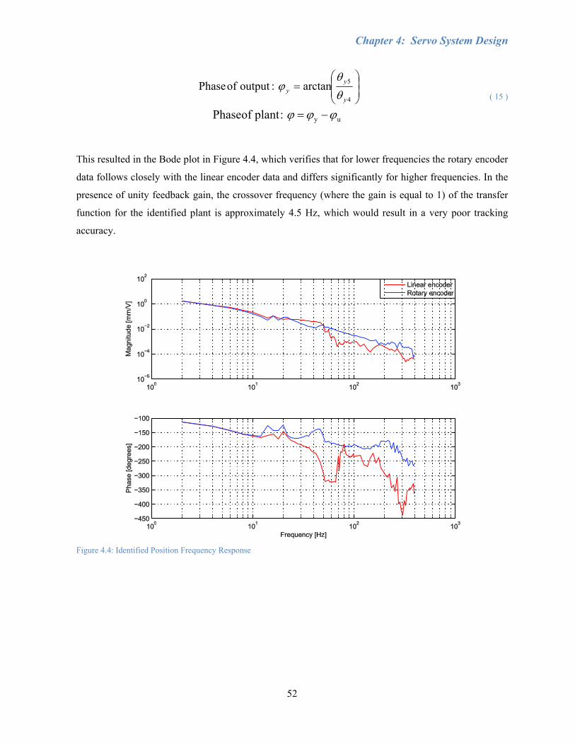
Chapter 4: Servo System Design
52
⎟⎟⎠
⎞⎜⎜⎝
⎛=
4
5arctan :output of Phase y
yy θ
θϕ
uy :plant of Phase ϕϕϕ −=
( 15 )
This resulted in the Bode plot in Figure 4.4, which verifies that for lower frequencies the rotary encoder
data follows closely with the linear encoder data and differs significantly for higher frequencies. In the
presence of unity feedback gain, the crossover frequency (where the gain is equal to 1) of the transfer
function for the identified plant is approximately 4.5 Hz, which would result in a very poor tracking
accuracy.
Figure 4.4: Identified Position Frequency Response
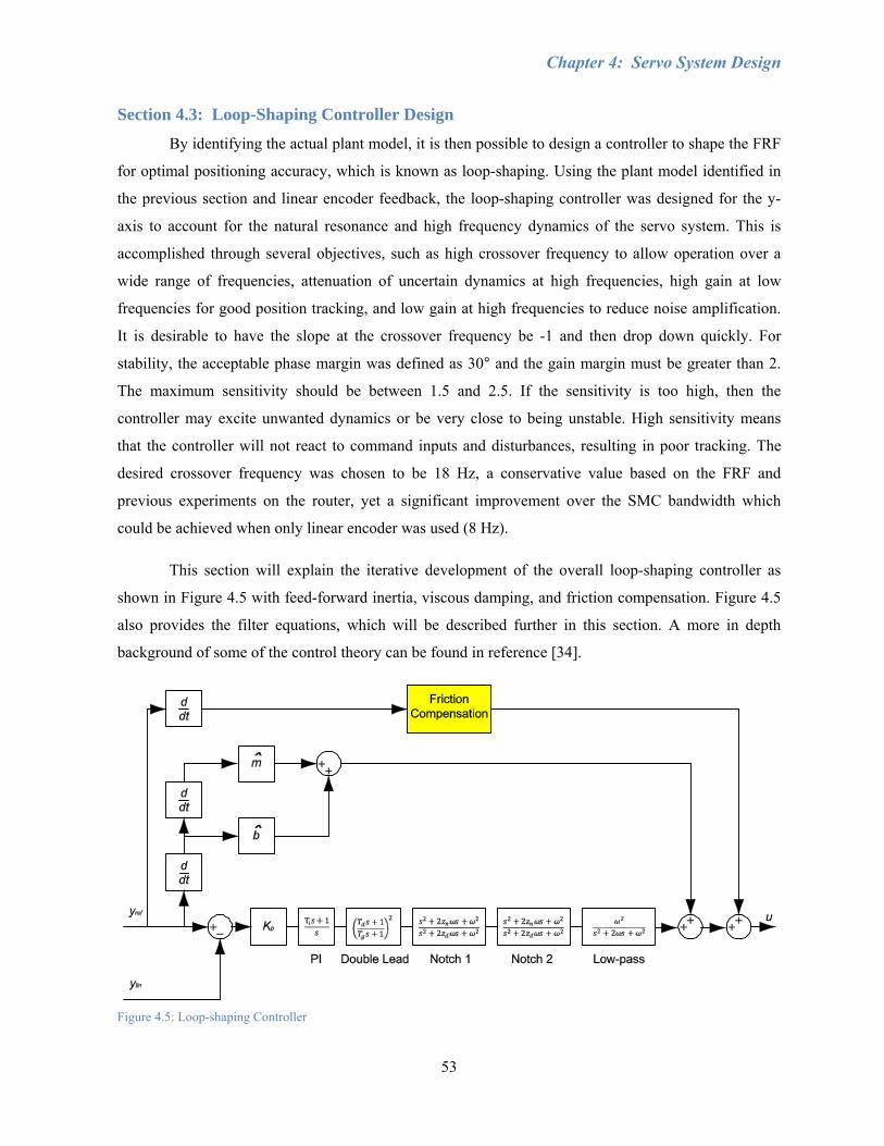
Chapter 4: Servo System Design
53
Section 4.3: Loop-Shaping Controller Design
By identifying the actual plant model, it is then possible to design a controller to shape the FRF
for optimal positioning accuracy, which is known as loop-shaping. Using the plant model identified in
the previous section and linear encoder feedback, the loop-shaping controller was designed for the y-
axis to account for the natural resonance and high frequency dynamics of the servo system. This is
accomplished through several objectives, such as high crossover frequency to allow operation over a
wide range of frequencies, attenuation of uncertain dynamics at high frequencies, high gain at low
frequencies for good position tracking, and low gain at high frequencies to reduce noise amplification.
It is desirable to have the slope at the crossover frequency be -1 and then drop down quickly. For
stability, the acceptable phase margin was defined as 30° and the gain margin must be greater than 2.
The maximum sensitivity should be between 1.5 and 2.5. If the sensitivity is too high, then the
controller may excite unwanted dynamics or be very close to being unstable. High sensitivity means
that the controller will not react to command inputs and disturbances, resulting in poor tracking. The
desired crossover frequency was chosen to be 18 Hz, a conservative value based on the FRF and
previous experiments on the router, yet a significant improvement over the SMC bandwidth which
could be achieved when only linear encoder was used (8 Hz).
This section will explain the iterative development of the overall loop-shaping controller as
shown in Figure 4.5 with feed-forward inertia, viscous damping, and friction compensation. Figure 4.5
also provides the filter equations, which will be described further in this section. A more in depth
background of some of the control theory can be found in reference [34].
Figure 4.5: Loop-shaping Controller
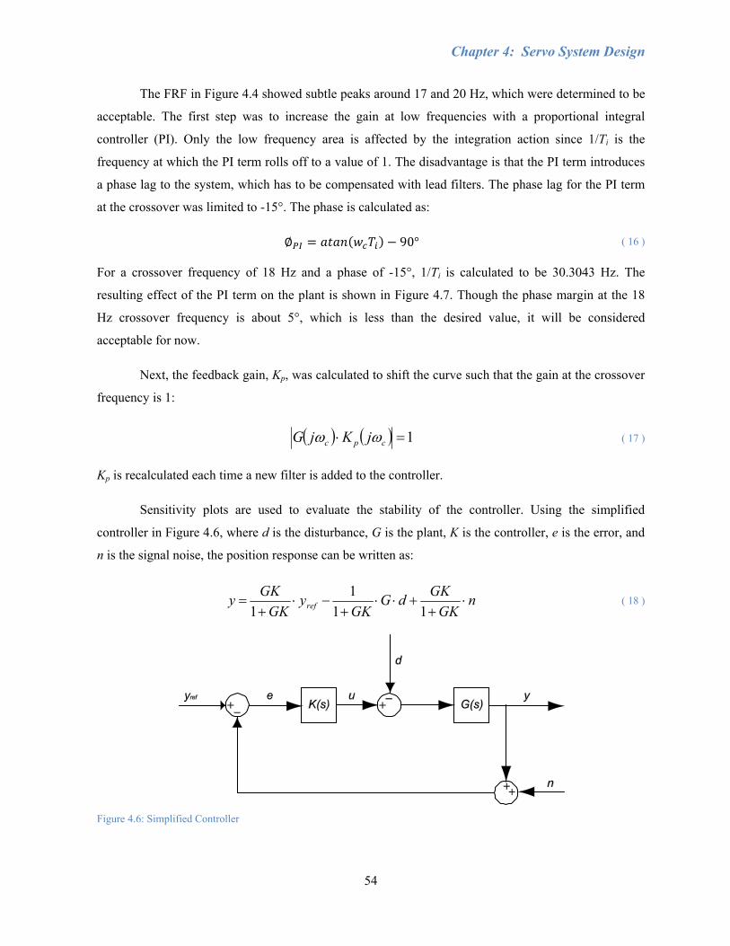
Chapter 4: Servo System Design
54
The FRF in Figure 4.4 showed subtle peaks around 17 and 20 Hz, which were determined to be
acceptable. The first step was to increase the gain at low frequencies with a proportional integral
controller (PI). Only the low frequency area is affected by the integration action since 1/Ti is the
frequency at which the PI term rolls off to a value of 1. The disadvantage is that the PI term introduces
a phase lag to the system, which has to be compensated with lead filters. The phase lag for the PI term
at the crossover was limited to -15°. The phase is calculated as:
90° ( 16 ) For a crossover frequency of 18 Hz and a phase of -15°, 1/Ti is calculated to be 30.3043 Hz. The
resulting effect of the PI term on the plant is shown in Figure 4.7. Though the phase margin at the 18
Hz crossover frequency is about 5°, which is less than the desired value, it will be considered
acceptable for now.
Next, the feedback gain, Kp, was calculated to shift the curve such that the gain at the crossover
frequency is 1:
( ) ( ) 1=⋅ cpc jKjG ωω ( 17 )
Kp is recalculated each time a new filter is added to the controller.
Sensitivity plots are used to evaluate the stability of the controller. Using the simplified
controller in Figure 4.6, where d is the disturbance, G is the plant, K is the controller, e is the error, and
n is the signal noise, the position response can be written as:
nGK
GKdGGK
yGK
GKy ref ⋅+
+⋅⋅+
−⋅+
=11
11
( 18 )
Figure 4.6: Simplified Controller
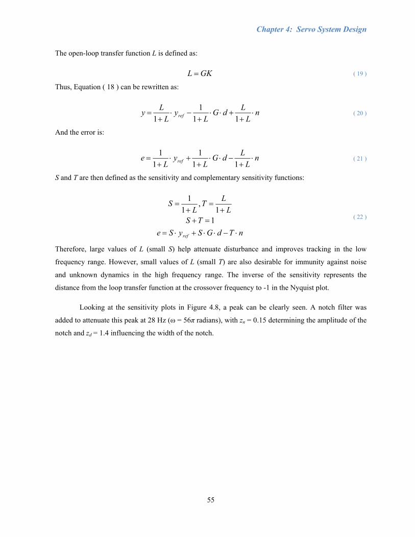
Chapter 4: Servo System Design
55
The open-loop transfer function L is defined as:
GKL = ( 19 )
Thus, Equation ( 18 ) can be rewritten as:
nL
LdGL
yL
Ly ref ⋅+
+⋅⋅+
−⋅+
=11
11
( 20 )
And the error is:
nL
LdGL
yL
e ref ⋅+
−⋅⋅+
+⋅+
=11
11
1 ( 21 )
S and T are then defined as the sensitivity and complementary sensitivity functions:
nTdGSySeTS
LLT
LS
ref ⋅−⋅⋅+⋅==+
+=
+=
11
,1
1
( 22 )
Therefore, large values of L (small S) help attenuate disturbance and improves tracking in the low
frequency range. However, small values of L (small T) are also desirable for immunity against noise
and unknown dynamics in the high frequency range. The inverse of the sensitivity represents the
distance from the loop transfer function at the crossover frequency to -1 in the Nyquist plot.
Looking at the sensitivity plots in Figure 4.8, a peak can be clearly seen. A notch filter was
added to attenuate this peak at 28 Hz (ω = 56π radians), with zn = 0.15 determining the amplitude of the
notch and zd = 1.4 influencing the width of the notch.
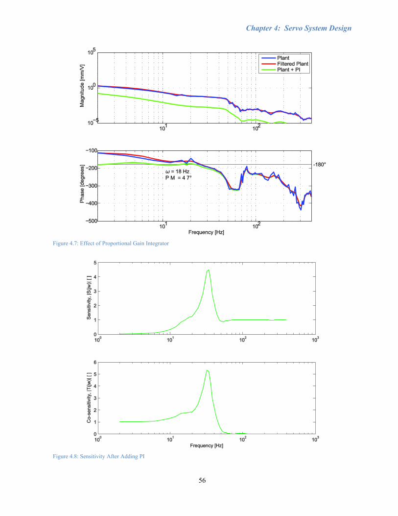
Chapter 4: Servo System Design
56
Figure 4.7: Effect of Proportional Gain Integrator
Figure 4.8: Sensitivity After Adding PI
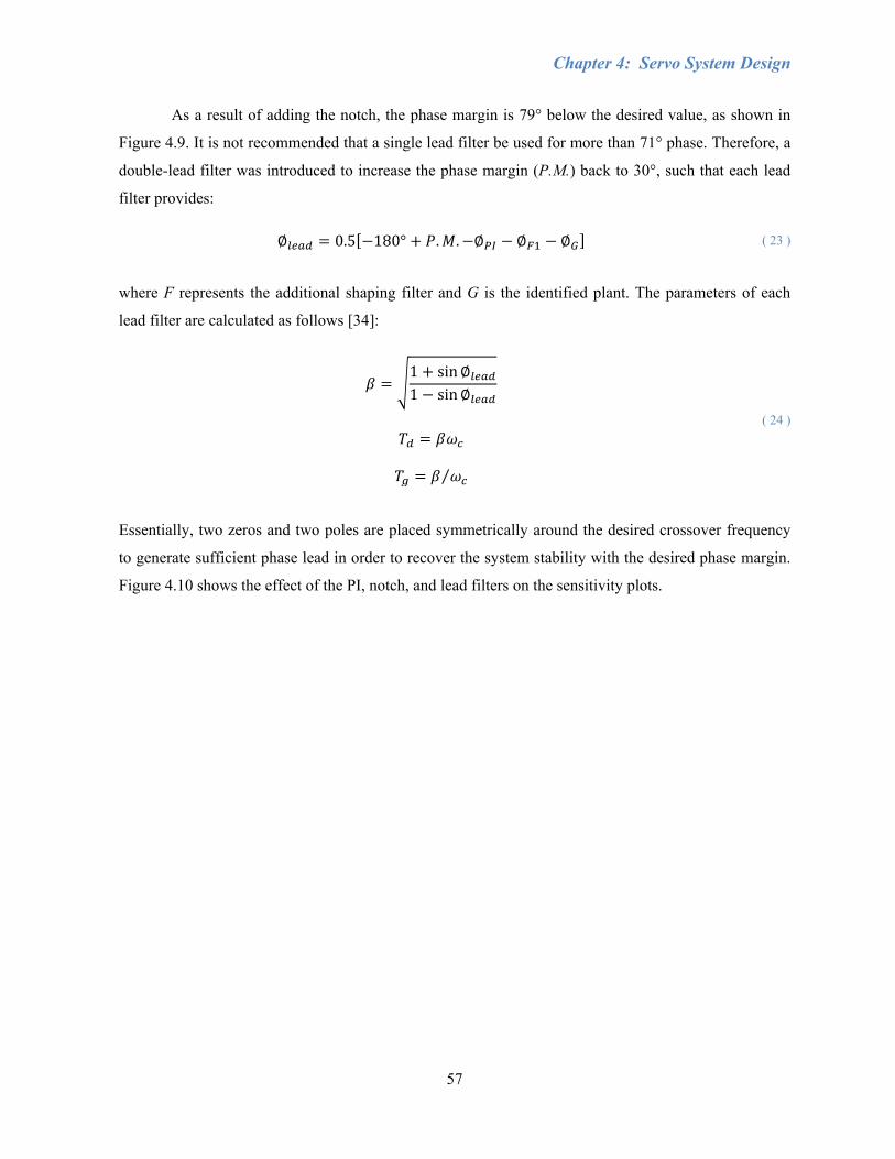
Chapter 4: Servo System Design
57
As a result of adding the notch, the phase margin is 79° below the desired value, as shown in
Figure 4.9. It is not recommended that a single lead filter be used for more than 71° phase. Therefore, a
double-lead filter was introduced to increase the phase margin (P.M.) back to 30°, such that each lead
filter provides:
0.5 180° . . ( 23 )
where F represents the additional shaping filter and G is the identified plant. The parameters of each
lead filter are calculated as follows [34]:
1 sin1 sin
⁄
( 24 )
Essentially, two zeros and two poles are placed symmetrically around the desired crossover frequency
to generate sufficient phase lead in order to recover the system stability with the desired phase margin.
Figure 4.10 shows the effect of the PI, notch, and lead filters on the sensitivity plots.
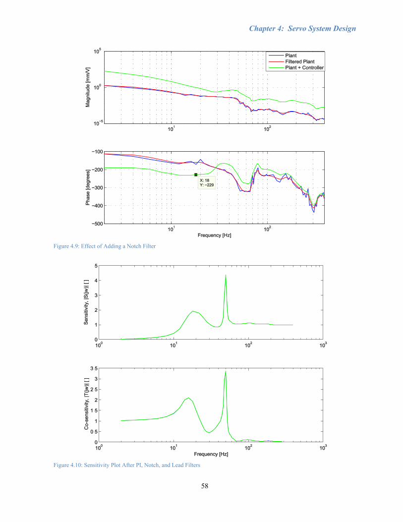
Chapter 4: Servo System Design
58
Figure 4.9: Effect of Adding a Notch Filter
Figure 4.10: Sensitivity Plot After PI, Notch, and Lead Filters
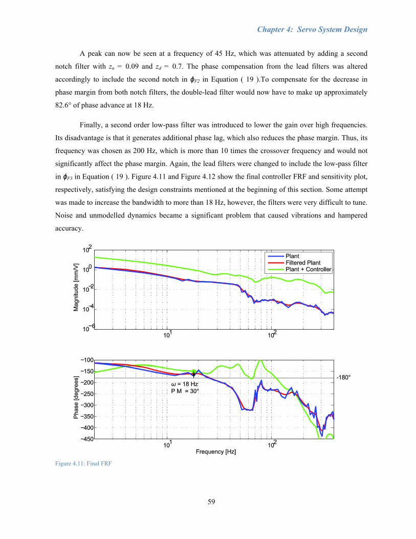
Chapter 4: Servo System Design
59
A peak can now be seen at a frequency of 45 Hz, which was attenuated by adding a second
notch filter with zn = 0.09 and zd = 0.7. The phase compensation from the lead filters was altered
accordingly to include the second notch in ϕF2 in Equation ( 19 ).To compensate for the decrease in
phase margin from both notch filters, the double-lead filter would now have to make up approximately
82.6° of phase advance at 18 Hz.
Finally, a second order low-pass filter was introduced to lower the gain over high frequencies.
Its disadvantage is that it generates additional phase lag, which also reduces the phase margin. Thus, its
frequency was chosen as 200 Hz, which is more than 10 times the crossover frequency and would not
significantly affect the phase margin. Again, the lead filters were changed to include the low-pass filter
in ϕF3 in Equation ( 19 ). Figure 4.11 and Figure 4.12 show the final controller FRF and sensitivity plot,
respectively, satisfying the design constraints mentioned at the beginning of this section. Some attempt
was made to increase the bandwidth to more than 18 Hz, however, the filters were very difficult to tune.
Noise and unmodelled dynamics became a significant problem that caused vibrations and hampered
accuracy.
Figure 4.11: Final FRF
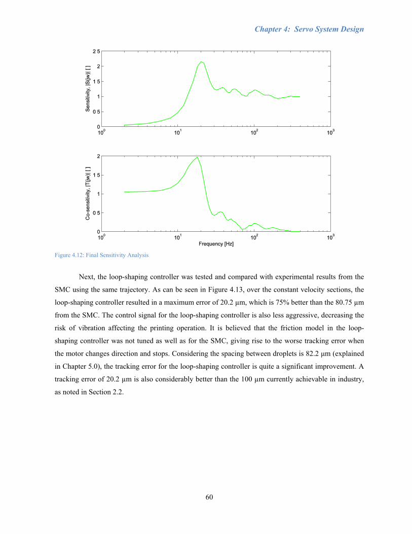
Chapter 4: Servo System Design
60
Figure 4.12: Final Sensitivity Analysis
Next, the loop-shaping controller was tested and compared with experimental results from the
SMC using the same trajectory. As can be seen in Figure 4.13, over the constant velocity sections, the
loop-shaping controller resulted in a maximum error of 20.2 µm, which is 75% better than the 80.75 µm
from the SMC. The control signal for the loop-shaping controller is also less aggressive, decreasing the
risk of vibration affecting the printing operation. It is believed that the friction model in the loop-
shaping controller was not tuned as well as for the SMC, giving rise to the worse tracking error when
the motor changes direction and stops. Considering the spacing between droplets is 82.2 μm (explained
in Chapter 5.0), the tracking error for the loop-shaping controller is quite a significant improvement. A
tracking error of 20.2 µm is also considerably better than the 100 µm currently achievable in industry,
as noted in Section 2.2.
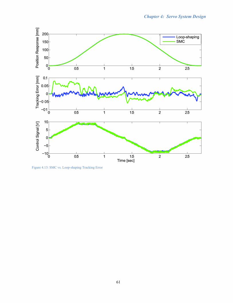
Chapter 4: Servo System Design
61
Figure 4.13: SMC vs. Loop-shaping Tracking Error

Chapter 4: Servo System Design
62
Section 4.4: Trajectory Generation & Axis Homing
While printing, the printheads must be kept at a height of 1 mm above the substrate. Since the
thickness of the substrate can change, the printheads should start at a predefined zero location and drop
down to the required 1 mm height. There is no vision detection for the substrate, so its thickness must
be incorporated into the trajectory prior to motion in order to calculate how far the printheads should be
lowered. When turning on the machine, the Z2 axis does not necessarily start at the zero location and
must be homed. Otherwise the printheads could crash into the substrate, thereby risking damage to the
printheads, the substrate, and the machine itself.
During the initial setup, the secondary z-axis was connected to the internal controller and the
limit switches of the router. This meant that the basic internal controller used by the router to home the
x, y, and z-axes could be used for the secondary z-axis instead of the spindle. It was found that the
motor dynamics of Z2 were very similar to Z1, which allowed for the switch. Ideally though, the
printhead mount and the spindle would both need to be in operation in order to print and machine
without constantly switching connections. Thus, a separate homing routine and mechanism were
developed for Z2 in MATLAB and Control Desk, which is a real-time program that can be used in
conjunction with the Simulink model.
The homing routine makes use of an encoder pulse produced every full revolution of the Z2
lead screw, which has a lead of 5.08 mm. In other words, for any position the lead screw should be
within 5.08 mm of the Z-pulse. Thus, as shown in Figure 4.14, the homing trajectory was designed such
that the lead screw would turn π radians clockwise (2.54 mm) and then 2π radians counter-clockwise
(5.08 mm), guaranteeing the detection of a single z-pulse. Once the pulse is detected, the Simulink
program was designed to reset the Z2 encoder to zero and the trajectory would turn off by simply
overriding the planned trajectory and sending zeroes to the controller instead. There is a slight
positioning correction of the lead screw due to the delay between the encoder reset and the trajectory
motion, where the linear stage will try to jump back to where it was before the encoder was reset, based
on the new zero position (Figure 4.15).
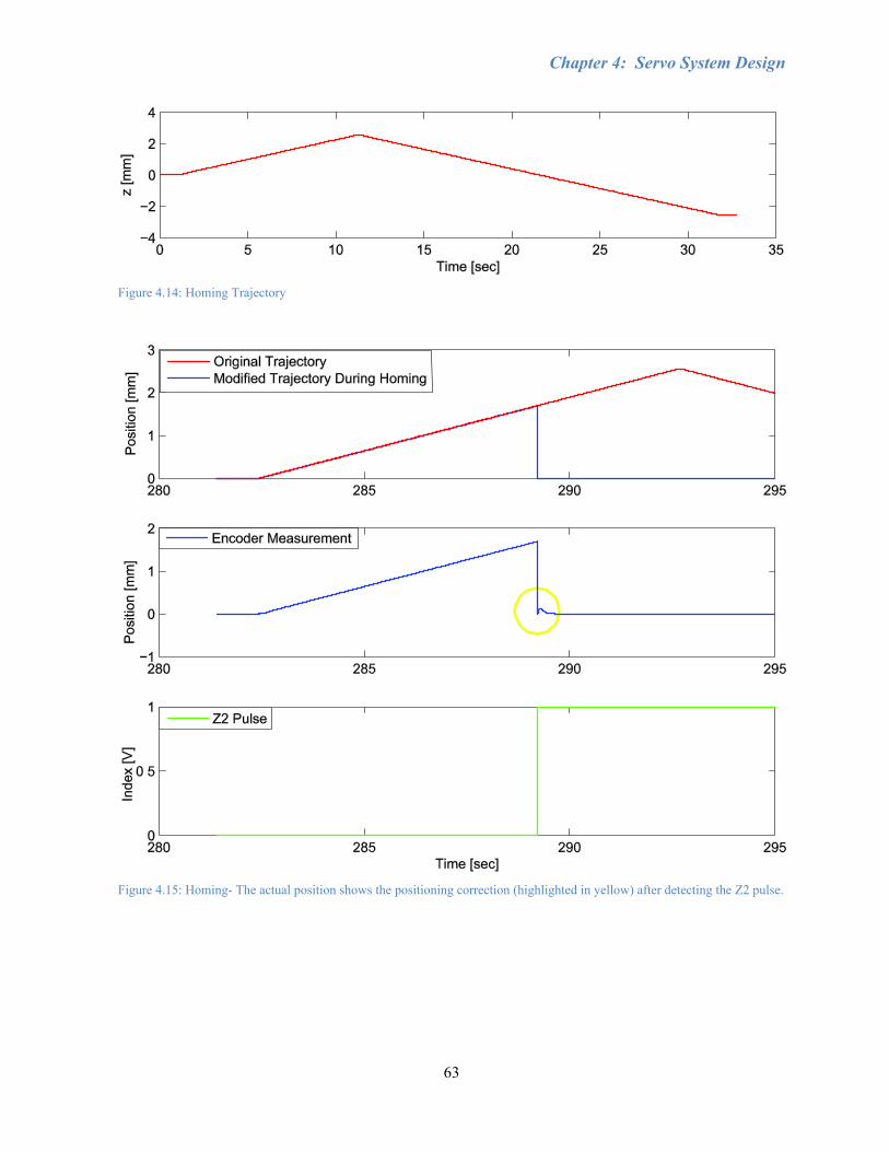
Chapter 4: Servo System Design
63
Figure 4.14: Homing Trajectory
Figure 4.15: Homing- The actual position shows the positioning correction (highlighted in yellow) after detecting the Z2 pulse.

Chapter 4: Servo System Design
64
This homing routine does not take into consideration the actual position of the printhead mount,
since there is no detection from the Z2 limit switches. The lead screw could be fully actuated, fully
retracted, or at some position in between. Hence, a manual jogging routine was developed in Control
Desk in conjunction with the Simulink model in order to position the printheads within range of a
specific location physically marked as the home position. Again, this is necessary since the trajectory to
plunge the printheads down needs to be built in advance by inputting the distance into the MATLAB
program. In this case, Control Desk is used to override the position commands and manually position
the printheads within range of home position when the program is paused and waiting for operator
acknowledgement (Figure 4.16). The X and Y axes were also included in the Control Desk interface to
more easily position the printheads over a specific area of the substrate and avoid having to constantly
switch back and forth between the internal router controller and dSPACE. However, in this thesis, a
homing routine has not been developed for the X and Y axes.
Loading the controllers to dSPACE takes a significant amount of time. Since the controller has
already been designed and should be stable at this point, the same controller implemented for printing
was used for jogging the axes instead of having to continuously switch between two different
controllers. In the Control Desk interface, the user specifies the distance and direction of travel as a
constant value. The constant position command is smoothed for jogging into continuous motion using
two low-pass filters, whose time constants determine how long it takes for the axes to travel the
specified distance. Once the desired position is reached, the axes are manually disabled and the
encoders are reset to zero. If the axes are not disabled first, then the delay between the encoder reset and
the control signal will cause the axis to jump to its previous zero location, which should not be done
when jogging large distances. The one exception is that since the Z2 motor will back-drive due to its
weight without the presence of a control signal, the Z2 axis must be constantly activated before running
the printing routine. Thus, it is recommended to first position the Z2 axis within 10 mm of home
position, disable the Z2 axis and then reset it. If the Z2 axis is still out of position, then the Z2 axis can
be kept activated, re-positioned, and then the encoders reset, which will cause it to attempt to move
back to its previous zero before settling at its new zero position.
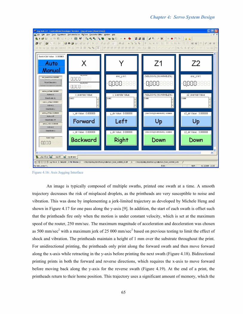
Chapter 4: Servo System Design
65
Figure 4.16: Axis Jogging Interface
An image is typically composed of multiple swaths, printed one swath at a time. A smooth
trajectory decreases the risk of misplaced droplets, as the printheads are very susceptible to noise and
vibration. This was done by implementing a jerk-limited trajectory as developed by Michele Heng and
shown in Figure 4.17 for one pass along the y-axis [9]. In addition, the start of each swath is offset such
that the printheads fire only when the motion is under constant velocity, which is set at the maximum
speed of the router, 250 mm/sec. The maximum magnitude of acceleration and deceleration was chosen
as 500 mm/sec2 with a maximum jerk of 25 000 mm/sec3 based on previous testing to limit the effect of
shock and vibration. The printheads maintain a height of 1 mm over the substrate throughout the print.
For unidirectional printing, the printheads only print along the forward swath and then move forward
along the x-axis while retracting in the y-axis before printing the next swath (Figure 4.18). Bidirectional
printing prints in both the forward and reverse directions, which requires the x-axis to move forward
before moving back along the y-axis for the reverse swath (Figure 4.19). At the end of a print, the
printheads return to their home position. This trajectory uses a significant amount of memory, which the
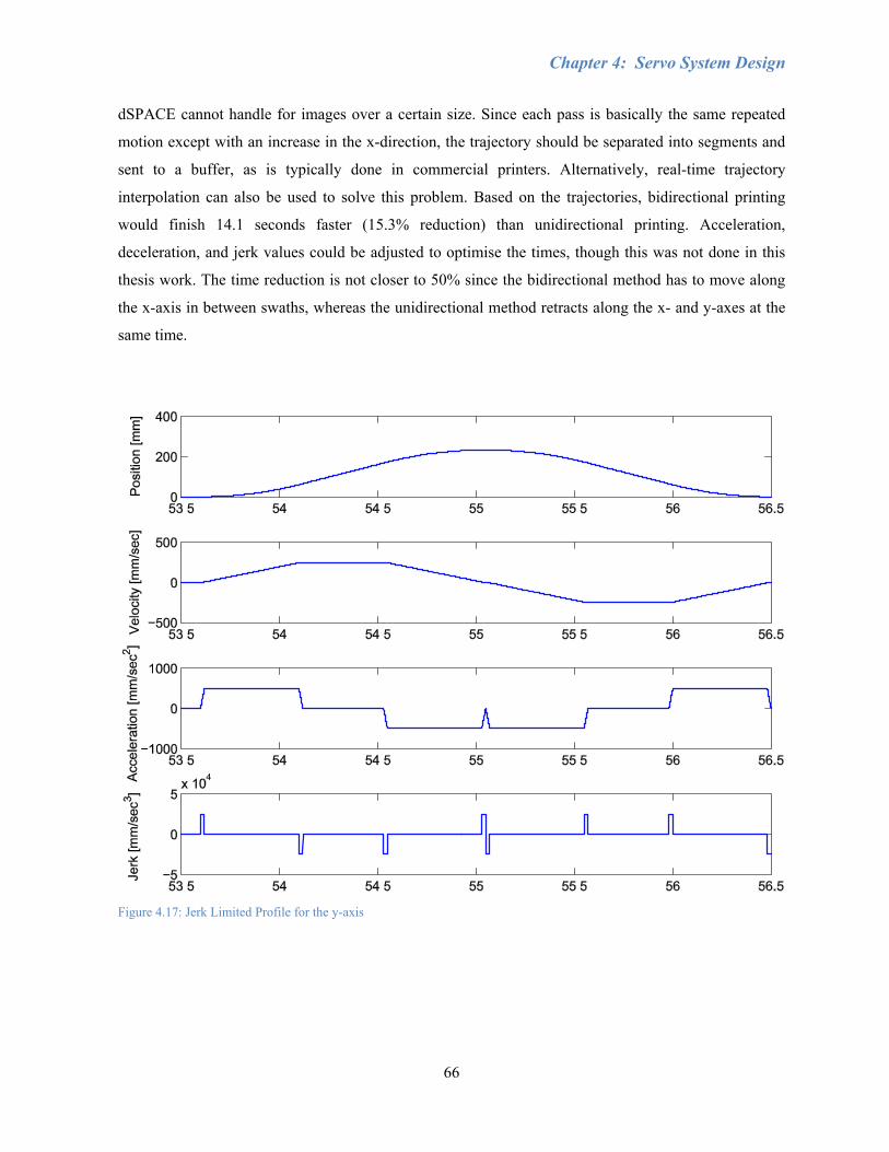
Chapter 4: Servo System Design
66
dSPACE cannot handle for images over a certain size. Since each pass is basically the same repeated
motion except with an increase in the x-direction, the trajectory should be separated into segments and
sent to a buffer, as is typically done in commercial printers. Alternatively, real-time trajectory
interpolation can also be used to solve this problem. Based on the trajectories, bidirectional printing
would finish 14.1 seconds faster (15.3% reduction) than unidirectional printing. Acceleration,
deceleration, and jerk values could be adjusted to optimise the times, though this was not done in this
thesis work. The time reduction is not closer to 50% since the bidirectional method has to move along
the x-axis in between swaths, whereas the unidirectional method retracts along the x- and y-axes at the
same time.
Figure 4.17: Jerk Limited Profile for the y-axis
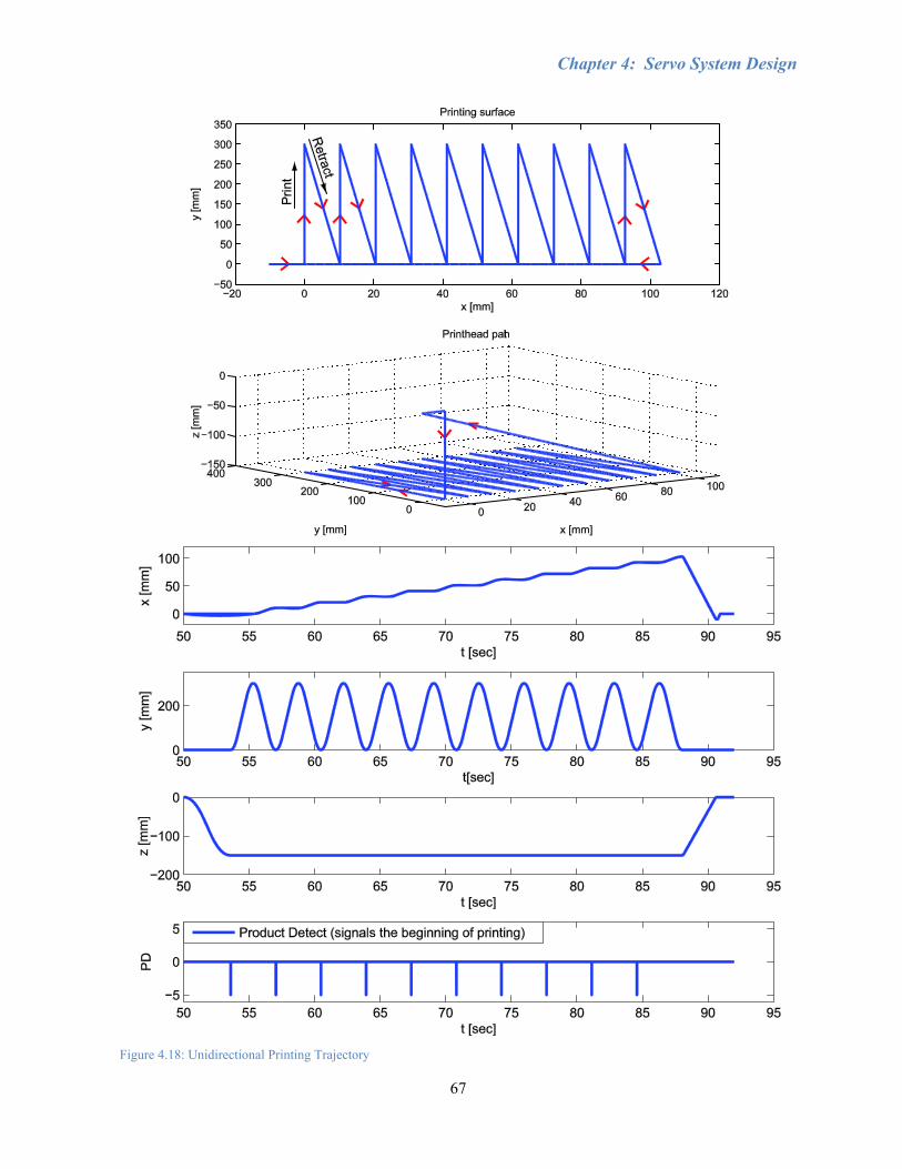
Chapter 4: Servo System Design
67
Figure 4.18: Unidirectional Printing Trajectory
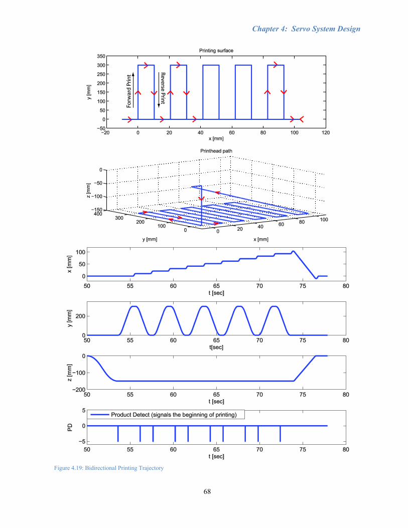
Chapter 4: Servo System Design
68
Figure 4.19: Bidirectional Printing Trajectory

Chapter 4: Servo System Design
69
Since the XUSB relies directly on the linear encoder measurements, smooth motion to reduce
noise in the signal becomes important rather than the positioning accuracy of the controller during
unidirectional printing. Tracking error is fairly repeatable, so each swath would be shifted by the same
amount. In 1PD bidirectional printing, the reverse PD is generated by the XUSB based on the linear
encoder measurements, which can be affected by noise, tilting and vibration of the printheads, and other
machine error. The 2PD bidirectional method would be better since it is adjusted by viewing the final
image, which includes these errors that are not detected by the linear encoder. However, when
generating 2 PD signals, there will be positioning error along the forward swath and an opposite
positioning error along the reverse swath; essentially doubling the error found in unidirectional printing.
Tuning the timing of the second PD signal based on the printed image will help, though the timing of
the signal is limited to the sampling rate of the controller. With a 5 kHz sampling period and 250
mm/sec motion, the printheads will travel 50 µm for each time step. If the true position of the PD signal
is in between each 50 µm step due to tracking error, then the only way to further improve the swath to
swath positioning accuracy is through controller design to reduce tracking error.
Chapter 4: Servo System Design
70
Section 4.5: Conclusions
In this chapter, the controller design for improved tracking control and droplet placement
accuracy was explained, which is essential for printing quality images using the 2PD bidirectional
method and when milling shapes around the printed image features. A loop-shaping controller was
designed with better performance than an SMC by identifying the actual plant FRF. This was achieved
by injecting sinusoidal excitation signals into the control signal and using least squares fitting to
estimate the input and output amplitude and phase values at each frequency. A proportional gain
integrator was used to increase the gain at low frequencies for better tracking and rejection of
disturbances, such as friction and cutting forces. Two notch filters were added to remove the resonances
found in the sensitivity function, and a double-lead filter compensated for the phase loss due to the
dynamics of the drive and added filters. Lastly, a second order low-pass filter was incorporated to lower
the gain at high frequencies. The loop-shaping controller improved the maximum tracking error over
the SMC during 250 mm/sec motion from roughly 80.75 to 20.2 µm.
It was necessary to develop a homing routine since the print trajectory is planned in advance of
motion and there is no visual detection system. A Control Desk interface was developed to manually
move the printhead mount within the range of a predefined home position along all three axes. Then,
the homing routine was implemented for the secondary Z-axis based on the 5.08 mm lead and the Z-
pulse from the encoder. To prevent back-driving of the printhead mount due to its weight, the Z2 axis
should be kept activated throughout homing and printing. A jerk-limited trajectory was used to ensure
smooth motion in order to avoid vibrating during the firing pulses. It was found that bidirectional
printing would be approximately 15% faster than unidirectional printing.
71
Chapter 5: Inkjet Printing Calibration The human eye possesses excellent visual acuity, given that a person with normal 20/20 vision
is capable of resolving discrepancies as small as 1 minute of arc (1/60 of a degree) [35]. This means
that, for example, if an image is 300 mm away from the eye, then the smallest distance a dot can be
distinguished from another dot is 0.087 mm. A print resolution of 309 dots per inch (DPI) results in a
centre-to-centre dot separation of 0.082 mm, such that any mono-colour print resolution higher than 309
DPI is sharp and adequate for most purposes, and a resolution of less than 309 DPI may result in
noticeably pixelated or blurry images or jagged edges. Calibration is thus an extremely crucial process
for an inkjet printing system since accurate placement of ink droplets, in addition to droplet
absorbability with the substrate, defines the resolution, and in turn, the quality of the image. However,
one must keep in mind that 20/20 vision is just an average that has been deemed acceptable for human
eyesight, though there are people who have better than 20/20 vision. As well, for future material
deposition applications in areas such as MEMS or nanotechnology, a much higher resolution would be
necessary. A detailed explanation of the calibration process followed in this thesis is given in Section
5.1.
Colour printing, on the other hand, is a much more complicated process than monochrome
printing. With a CMYK printer, most colours besides cyan, magenta, yellow, and black are made up of
some combination of the other colours and white, which is typically the assumed colour for the
substrate. White spaces help lighten colours and black dots darken them. For example, green would be
mostly composed of cyan and yellow, with some magenta, black, and blank dots depending on the
shade of green. If all these dots were the same size, as it is for binary printing, and were to be deposited
in a single position, then the result would be a black dot of diameter larger than 0.087 mm. Thus, for the
binary printing system developed in this work, error diffusion dithering is used to simulate the desired
colours by spreading out the droplets of each individual colour, which means that the resolution for a
colour image is significantly less than 309 DPI. It is easy to acknowledge that even slight colour
changes are readily distinguished with the human eye, and therefore a higher resolution would be
needed for colour printing. Greyscale printing would also be another option to improve colour
resolution, since dot size is more controllable and several colours could potentially make up one pixel.
Colour is an exhaustive field that will not be investigated here beyond qualitative judgement.
Recalling the layout of the printhead mounting plate in Section 3.2.1, in order to achieve a
specific resolution, the printheads need to be aligned at a specific angle, as well as have close alignment
with the other printheads both vertically and horizontally. Mechanical alignment (i.e. making slight
Chapter 5: Inkjet Printing Calibration
72
changes in angle and vertical alignment where necessary) is done through the adjustment screws
holding the printheads in position with respect to spring-loaded thrust pins. Software settings for the
printhead controller allow for changes in horizontal offsets that can be applied to each printhead
individually in terms of number of pixels. Large images are printed with multiple swaths, where each
swath is printed in the direction of the printhead sweeping motion. This means that each swath must be
placed directly below the previous swath, or else the image will have a jagged appearance. Vertical
displacement between swaths is determined by the trajectory and the motion control system.
It was found that printing on non-glossy paper such as Xerox Premium Inkjet paper weighing
90 g/m2 would allow the ink to absorb into the fibres of the paper, making quantitative microscopic
analysis much more difficult, even though the image is aesthetically fine. Therefore, testing was done
with HP Premium Plus Photo Paper, which is 280 g/m2 high gloss paper designed for inkjet printing.
The oil-based ink did not absorb into the glossy paper since HP uses water-based ink with thermal
inkjet technology, where the ink solidifies after cooling, rather than piezoelectric, which relies on
absorption or evaporation. However, that is exactly why the high gloss paper was ideal for testing
calibration. Since the droplets do not absorb into the paper, they remain in the exact position and shape
in which they were deposited with minimal distortion. The disadvantage is that factors such as physical
contact, air convection, imperfections in the paper surface, dust contamination, tilting the sample, and
settling time could affect the droplets while preparing and transporting the sample to a microscope. [18]
Section 5.2 will present the verification results from calibrating the printheads and the problems
involved. This section is further divided into subsections by implementing one element at a time,
starting from a unidirectional monochrome print to a full-colour bidirectional image for reduced
production time. All tests were done using the loop-shaping controller developed in Section 4.3 for the
y-axis motion. Section 5.3 details the additional issues encountered while printing and how they were
resolved, including printhead maintenance. Section 5.4 gives the conclusions for this chapter.

Chapter 5: Inkjet Printing Calibration
73
Section 5.1: Printhead Calibration Methodology and Operation
Calibration can be separated into mechanical and software components. First, the printheads
were manually aligned by tightening or loosening the adjustment screws that hold the printheads in
place. The tapered heads of the adjustment screws determine how far the printhead is pushed against the
thrust pin, which can be considered a deformable spring. This means the fixed reference point changes
depending on which screw is being adjusted, making adjustment more complicated. As shown in Figure
5.1, by tightening screw A, the force will push the thrust pin (highlighted in green) down and to the left
and the printhead will rotate counter-clockwise around screw B. Conversely, tightening screw B will
move the thrust pin up and to the left and rotates the printhead clockwise about screw A. The more a
screw is tightened, the greater the force it exerts against the printhead and thrust pin. However, one
screw can limit the extent to which the other screw affects the printhead. For example, if both screws
are significantly tightened and screw A is tightened further, screw B will prevent the printhead from
shifting down further until screw B is loosened. Quantification to ascertain exact printhead
displacement in relation to screw rotation was concluded to be outside the scope of this thesis. It should
be noted that the adjustment screws are only for minor adjustments since the printhead angle is mainly
determined by the mounting plate. Excessive tightening may bend the thrust pin and cause it to break.
Figure 5.1: Direction of Printhead Adjustment - Turning adjustment screws A or B results in the corresponding motion of the .printhead (outlined in red) and the thrust pin (highlighted in green).
Software calibration is controlled through the XUSB software provided by the printhead
manufacturer, Xaar, and MATLAB trajectory generation. In the XUSB software, each printhead has an
offset in units of pixels that determines the distance that the printhead should delay after receiving the
B
A A
B
x
y
Chapter 5: Inkjet Printing Calibration
74
product detect signal to start printing in each swath. Since there is a gap between each printhead, the
offsets will need to be adjusted accordingly, increasing with their respective distances from the first
printhead. The trajectory determines how far the printheads travel in the x-direction to the next swath.
In other words, the XUSB software has some control over the horizontal displacement, while the
trajectory controls the spacing between swaths, though not the spacing between droplets within a swath.
The results from printing on HP glossy paper were viewed under an Olympus microscope at
50x magnification, which was the lowest magnification available, and captured and measured using
Image-Pro 6.3 software. Samples were held down with tape while the platform on which the sample
rests can be jogged with a joystick to move around within the limited field of view. Microscope images
are inverted both horizontally and vertically. Thus, when printing two colours directly on top of each
other, if the dots of one colour appear to be offset to the right of the other, then it is actually shifted too
far left and requires a respective change in offset value or a mechanical shift to the right to align with
the other colour. Conversely, the angular adjustment direction is the same as viewed under the
microscope, since the horizontal and vertical flips are equivalent to a rotation of 180 degrees. However,
it is much easier to adjust the printheads in terms of horizontal and vertical movement. It should be
noted that the colour depicted in the microscope images of printed results may not reflect the actual
colour of the sample due to various visual settings in the Image-Pro software.
Droplets are ejected from the printhead nozzles using piezoelectric shear mode firing (Figure
5.2). The nozzles eject ink when the two walls of a nozzle are activated by an electric field, supplied by
metal electrodes on the upper half of both sides of the channel wall. Voltage signals applied to the
electrodes produce shear mode deformation of the upper halves of the walls and the lower halves follow
their motion. As the walls move outwards, the pressure within the channel is reduced. Acoustic waves
restore atmospheric pressure to bring fluid into the channel. The waves cross in the middle, producing a
high pressure region in the centre. When one acoustic period passes, which is the time for a wave to
travel the length of the channel, the pressure along the channel is elevated. Next, a step in the waveform
applied to the channel and an opposing step in the waveform of the neighbouring channels cause the
walls to move inwards, creating more pressure. Finally, acoustic rarefaction waves reduce the pressure
back to atmospheric level, which allows fluid to flow into the nozzle to produce a droplet. Since the two
walls of a channel are shared by its neighbouring channels, this means that the nozzles must be
separated into at least groups of three to prevent undesired firing. The nozzles within each group are
known as A, B, and C channels. For example, if the nozzles were split into only two groups, A and B,
and all the A channels were activated, then the B channels would also fire since they share two walls
with two A channels. [13, 36, 37]
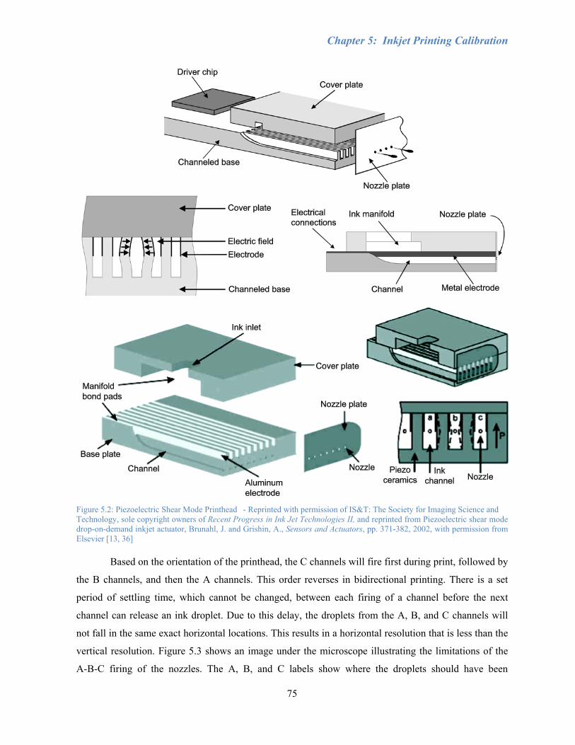
Chapter 5: Inkjet Printing Calibration
75
Figure 5.2: Piezoelectric Shear Mode Printhead - Reprinted with permission of IS&T: The Society for Imaging Science and Technology, sole copyright owners of Recent Progress in Ink Jet Technologies II, and reprinted from Piezoelectric shear mode drop-on-demand inkjet actuator, Brunahl, J. and Grishin, A., Sensors and Actuators, pp. 371-382, 2002, with permission from Elsevier [13, 36] Based on the orientation of the printhead, the C channels will fire first during print, followed by
the B channels, and then the A channels. This order reverses in bidirectional printing. There is a set
period of settling time, which cannot be changed, between each firing of a channel before the next
channel can release an ink droplet. Due to this delay, the droplets from the A, B, and C channels will
not fall in the same exact horizontal locations. This results in a horizontal resolution that is less than the
vertical resolution. Figure 5.3 shows an image under the microscope illustrating the limitations of the
A-B-C firing of the nozzles. The A, B, and C labels show where the droplets should have been
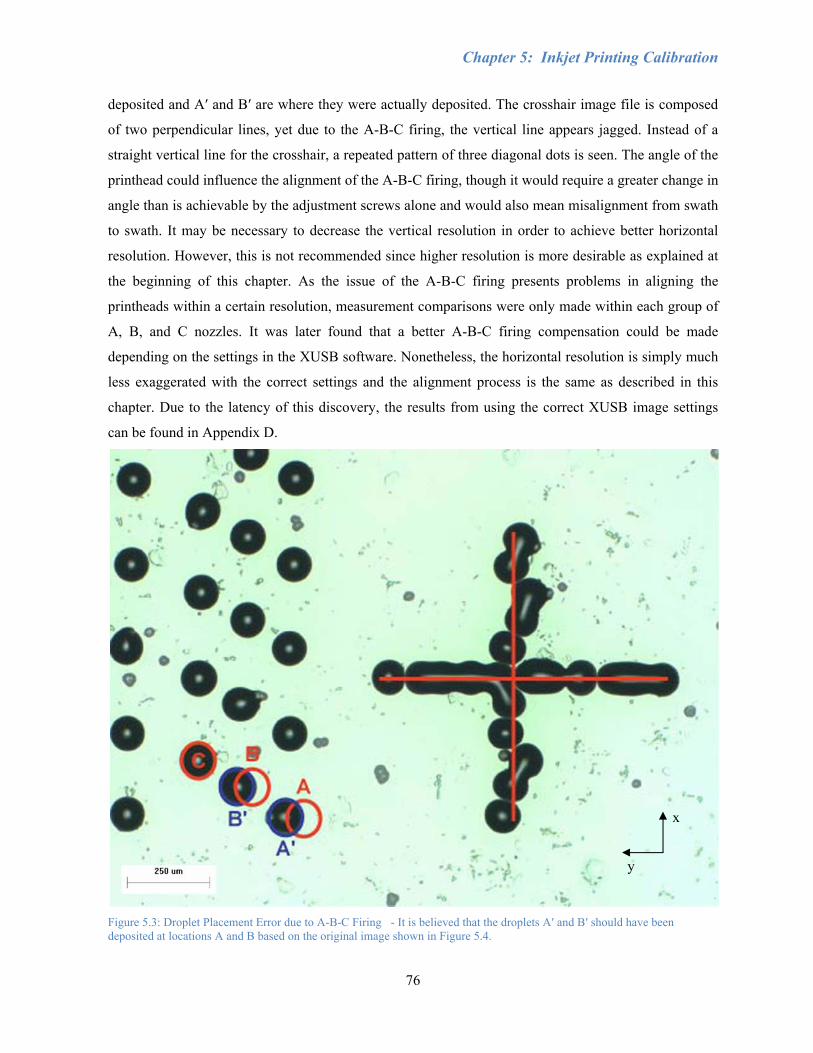
Chapter 5: Inkjet Printing Calibration
76
deposited and Aʹ and Bʹ are where they were actually deposited. The crosshair image file is composed
of two perpendicular lines, yet due to the A-B-C firing, the vertical line appears jagged. Instead of a
straight vertical line for the crosshair, a repeated pattern of three diagonal dots is seen. The angle of the
printhead could influence the alignment of the A-B-C firing, though it would require a greater change in
angle than is achievable by the adjustment screws alone and would also mean misalignment from swath
to swath. It may be necessary to decrease the vertical resolution in order to achieve better horizontal
resolution. However, this is not recommended since higher resolution is more desirable as explained at
the beginning of this chapter. As the issue of the A-B-C firing presents problems in aligning the
printheads within a certain resolution, measurement comparisons were only made within each group of
A, B, and C nozzles. It was later found that a better A-B-C firing compensation could be made
depending on the settings in the XUSB software. Nonetheless, the horizontal resolution is simply much
less exaggerated with the correct settings and the alignment process is the same as described in this
chapter. Due to the latency of this discovery, the results from using the correct XUSB image settings
can be found in Appendix D.
Figure 5.3: Droplet Placement Error due to A-B-C Firing - It is believed that the droplets Aʹ and Bʹ should have been deposited at locations A and B based on the original image shown in Figure 5.4.
x
y
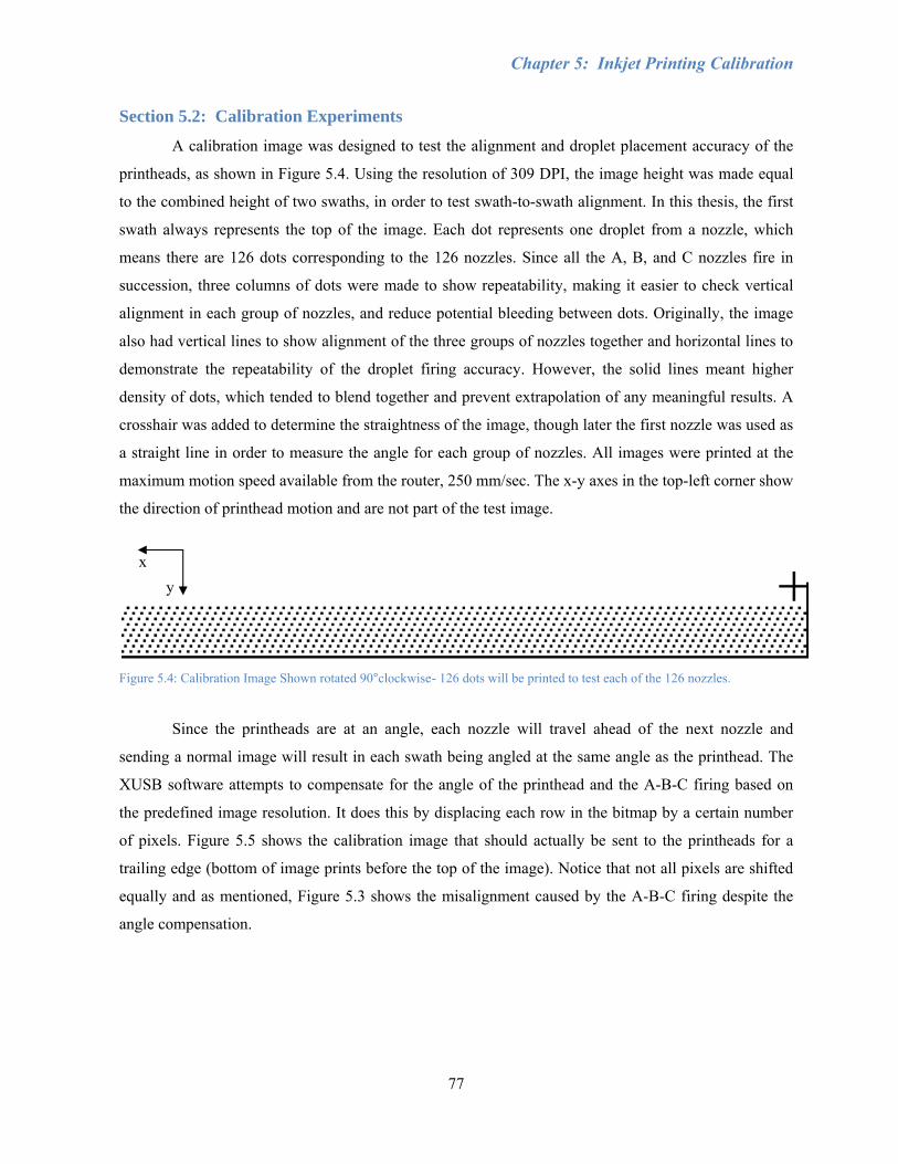
Chapter 5: Inkjet Printing Calibration
77
Section 5.2: Calibration Experiments
A calibration image was designed to test the alignment and droplet placement accuracy of the
printheads, as shown in Figure 5.4. Using the resolution of 309 DPI, the image height was made equal
to the combined height of two swaths, in order to test swath-to-swath alignment. In this thesis, the first
swath always represents the top of the image. Each dot represents one droplet from a nozzle, which
means there are 126 dots corresponding to the 126 nozzles. Since all the A, B, and C nozzles fire in
succession, three columns of dots were made to show repeatability, making it easier to check vertical
alignment in each group of nozzles, and reduce potential bleeding between dots. Originally, the image
also had vertical lines to show alignment of the three groups of nozzles together and horizontal lines to
demonstrate the repeatability of the droplet firing accuracy. However, the solid lines meant higher
density of dots, which tended to blend together and prevent extrapolation of any meaningful results. A
crosshair was added to determine the straightness of the image, though later the first nozzle was used as
a straight line in order to measure the angle for each group of nozzles. All images were printed at the
maximum motion speed available from the router, 250 mm/sec. The x-y axes in the top-left corner show
the direction of printhead motion and are not part of the test image.
Figure 5.4: Calibration Image Shown rotated 90°clockwise- 126 dots will be printed to test each of the 126 nozzles.
Since the printheads are at an angle, each nozzle will travel ahead of the next nozzle and
sending a normal image will result in each swath being angled at the same angle as the printhead. The
XUSB software attempts to compensate for the angle of the printhead and the A-B-C firing based on
the predefined image resolution. It does this by displacing each row in the bitmap by a certain number
of pixels. Figure 5.5 shows the calibration image that should actually be sent to the printheads for a
trailing edge (bottom of image prints before the top of the image). Notice that not all pixels are shifted
equally and as mentioned, Figure 5.3 shows the misalignment caused by the A-B-C firing despite the
angle compensation.
x y
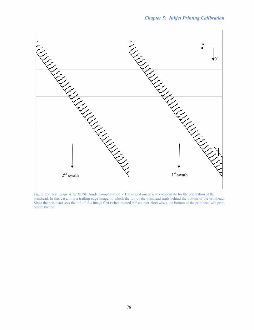
Chapter 5: Inkjet Printing Calibration
78
Figure 5.5: Test Image After XUSB Angle Compensation - The angled image is to compensate for the orientation of the printhead. In this case, it is a trailing edge image, in which the top of the printhead trails behind the bottom of the printhead. Since the printhead sees the left of this image first (when rotated 90° counter-clockwise), the bottom of the printhead will print before the top.
x
y
1st swath 2nd swath
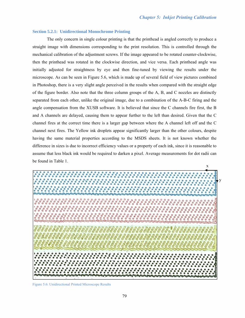
Chapter 5: Inkjet Printing Calibration
79
Section 5.2.1: Unidirectional Monochrome Printing
The only concern in single colour printing is that the printhead is angled correctly to produce a
straight image with dimensions corresponding to the print resolution. This is controlled through the
mechanical calibration of the adjustment screws. If the image appeared to be rotated counter-clockwise,
then the printhead was rotated in the clockwise direction, and vice versa. Each printhead angle was
initially adjusted for straightness by eye and then fine-tuned by viewing the results under the
microscope. As can be seen in Figure 5.6, which is made up of several field of view pictures combined
in Photoshop, there is a very slight angle perceived in the results when compared with the straight edge
of the figure border. Also note that the three column groups of the A, B, and C nozzles are distinctly
separated from each other, unlike the original image, due to a combination of the A-B-C firing and the
angle compensation from the XUSB software. It is believed that since the C channels fire first, the B
and A channels are delayed, causing them to appear further to the left than desired. Given that the C
channel fires at the correct time there is a larger gap between where the A channel left off and the C
channel next fires. The Yellow ink droplets appear significantly larger than the other colours, despite
having the same material properties according to the MSDS sheets. It is not known whether the
difference in sizes is due to incorrect efficiency values or a property of each ink, since it is reasonable to
assume that less black ink would be required to darken a pixel. Average measurements for dot radii can
be found in Table 1.
Figure 5.6: Unidirectional Printed Microscope Results
x
y
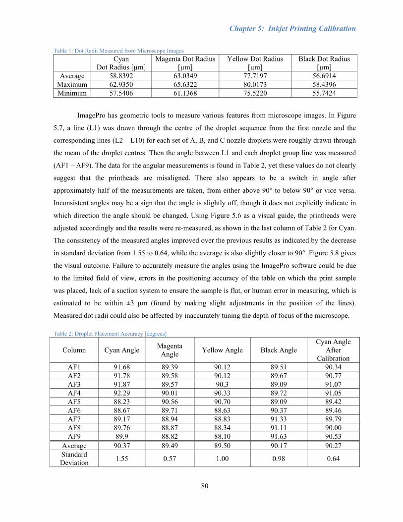
Chapter 5: Inkjet Printing Calibration
80
Table 1: Dot Radii Measured from Microscope Images
Cyan Dot Radius [µm]
Magenta Dot Radius [µm]
Yellow Dot Radius [µm]
Black Dot Radius [µm]
Average 58.8392 63.0349 77.7197 56.6914 Maximum 62.9350 65.6322 80.0173 58.4396 Minimum 57.5406 61.1368 75.5220 55.7424
ImagePro has geometric tools to measure various features from microscope images. In Figure
5.7, a line (L1) was drawn through the centre of the droplet sequence from the first nozzle and the
corresponding lines (L2 – L10) for each set of A, B, and C nozzle droplets were roughly drawn through
the mean of the droplet centres. Then the angle between L1 and each droplet group line was measured
(AF1 – AF9). The data for the angular measurements is found in Table 2, yet these values do not clearly
suggest that the printheads are misaligned. There also appears to be a switch in angle after
approximately half of the measurements are taken, from either above 90° to below 90° or vice versa.
Inconsistent angles may be a sign that the angle is slightly off, though it does not explicitly indicate in
which direction the angle should be changed. Using Figure 5.6 as a visual guide, the printheads were
adjusted accordingly and the results were re-measured, as shown in the last column of Table 2 for Cyan.
The consistency of the measured angles improved over the previous results as indicated by the decrease
in standard deviation from 1.55 to 0.64, while the average is also slightly closer to 90°. Figure 5.8 gives
the visual outcome. Failure to accurately measure the angles using the ImagePro software could be due
to the limited field of view, errors in the positioning accuracy of the table on which the print sample
was placed, lack of a suction system to ensure the sample is flat, or human error in measuring, which is
estimated to be within ±3 µm (found by making slight adjustments in the position of the lines).
Measured dot radii could also be affected by inaccurately tuning the depth of focus of the microscope.
Table 2: Droplet Placement Accuracy [degrees]
Column Cyan Angle Magenta Angle Yellow Angle Black Angle
Cyan Angle After
Calibration AF1 91.68 89.39 90.12 89.51 90.34 AF2 91.78 89.58 90.12 89.67 90.77 AF3 91.87 89.57 90.3 89.09 91.07 AF4 92.29 90.01 90.33 89.72 91.05 AF5 88.23 90.56 90.70 89.09 89.42 AF6 88.67 89.71 88.63 90.37 89.46 AF7 89.17 88.94 88.83 91.33 89.79 AF8 89.76 88.87 88.34 91.11 90.00 AF9 89.9 88.82 88.10 91.63 90.53
Average 90.37 89.49 89.50 90.17 90.27 Standard Deviation 1.55 0.57 1.00 0.98 0.64
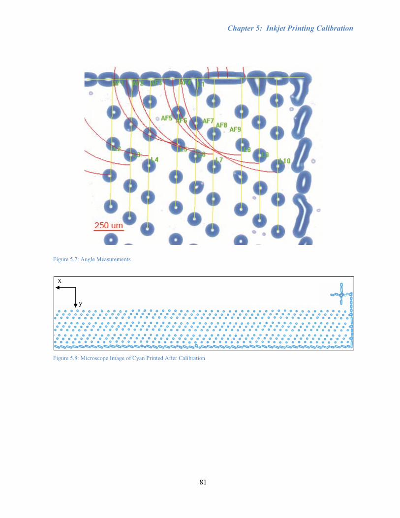
Chapter 5: Inkjet Printing Calibration
81
Figure 5.7: Angle Measurements
Figure 5.8: Microscope Image of Cyan Printed After Calibration
x
y

Chapter 5: Inkjet Printing Calibration
82
Section 5.2.2: Unidirectional Multi-colour Printing
In multi-colour printing, each printhead must be aligned with the other printheads such that
each droplet from the nozzles of one printhead will directly overlap the droplets from the nozzles of the
next printhead when the same image is sent to both printheads. This requires vertical alignment by
mechanical adjustment from the screws and horizontal alignment achieved through the software offsets.
First, it was assumed that one printhead was in the correct position, and then each printhead was aligned
relative to the first printhead. It may be necessary to recheck the alignment of each printhead, in case
the angle was accidentally changed during the vertical calibration. Test images were viewed as soon as
possible after printing, since the inks merged together after extended periods of time and any difference
in alignment between the two colours would be indistinguishable.
For example, when aligning magenta with cyan, if magenta printed too late, then the offset
value in the XUSB software was decreased. Similarly, if magenta printed too early, then the offset
value was increased. If the magenta image was printed slightly lower than the cyan image, then it would
need to be shifted up using the adjustment screws. Both screws would need to be adjusted equally so as
not to shift the angle. In the first image of Figure 5.9, with Magenta overlapping Cyan, the dots are
slightly distorted, indicating that the two colours are not perfectly aligned. The Magenta printhead
needs to be shifted to the right and slightly upward, which could be accomplished by loosening screw
A, loosening screw B, or some combination of both. It may even be necessary to decrease the delay for
the magenta printhead in the XUSB software. An attempt was made to measure the distortion between
Cyan and Magenta, as shown in Appendix D. Since the dots were not very circular, the smallest and
largest diameters were taken. The average of the large diameters was actually roughly equal to the
radius of dots when Cyan and Magenta are correctly aligned, so it is difficult to use this information
when aligning the printheads.
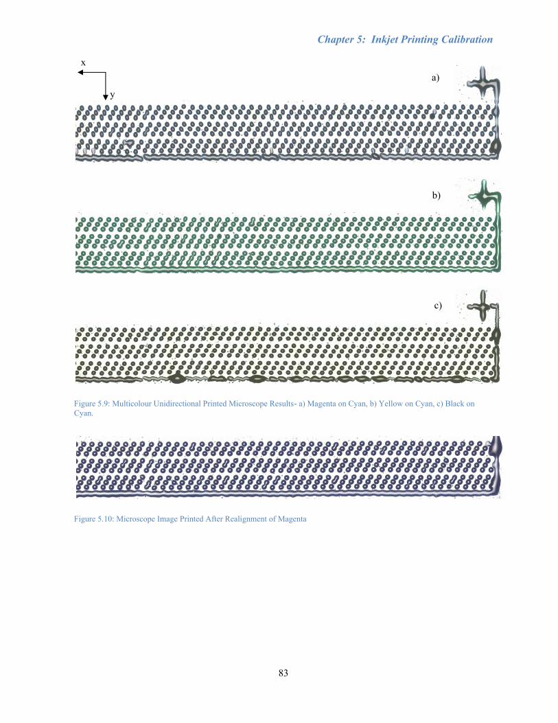
Chapter 5: Inkjet Printing Calibration
83
Figure 5.9: Multicolour Unidirectional Printed Microscope Results- a) Magenta on Cyan, b) Yellow on Cyan, c) Black on Cyan.
Figure 5.10: Microscope Image Printed After Realignment of Magenta
x
y
a)
c)
b)
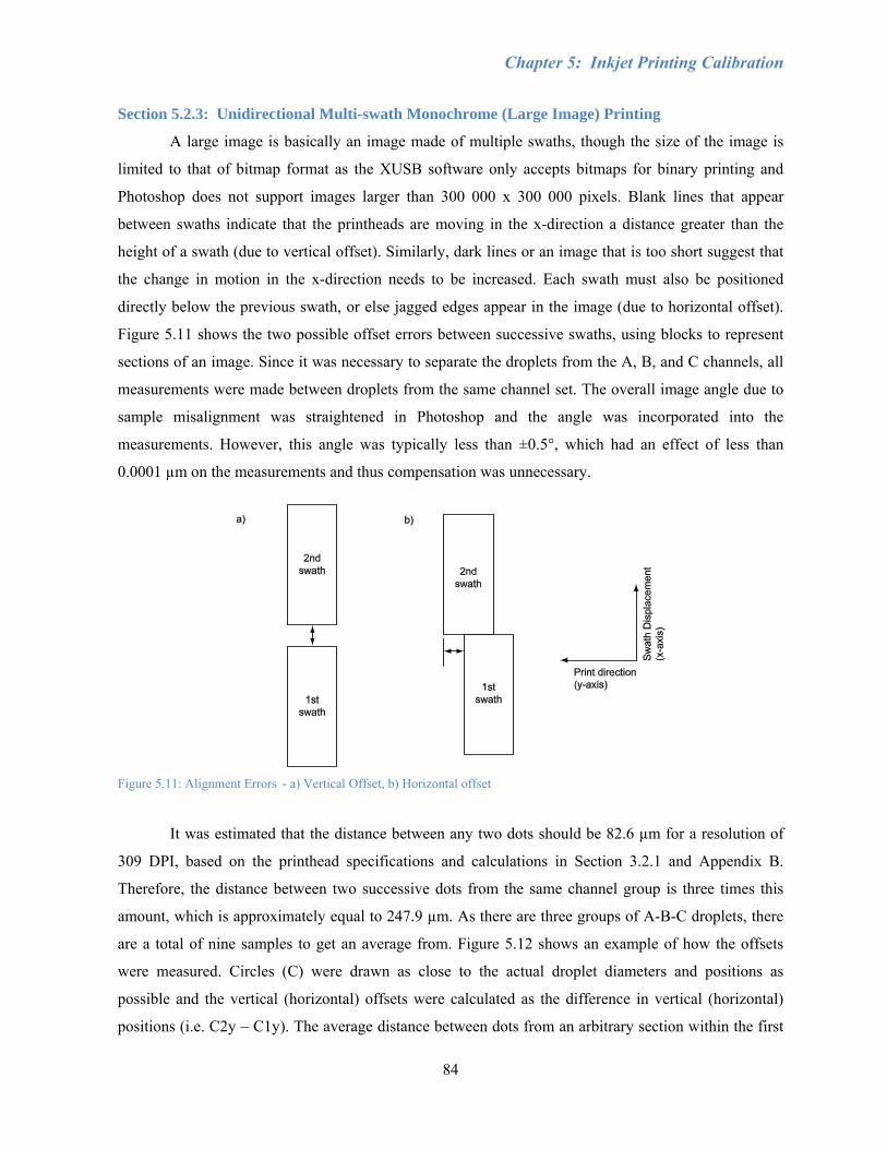
Chapter 5: Inkjet Printing Calibration
84
Section 5.2.3: Unidirectional Multi-swath Monochrome (Large Image) Printing
A large image is basically an image made of multiple swaths, though the size of the image is
limited to that of bitmap format as the XUSB software only accepts bitmaps for binary printing and
Photoshop does not support images larger than 300 000 x 300 000 pixels. Blank lines that appear
between swaths indicate that the printheads are moving in the x-direction a distance greater than the
height of a swath (due to vertical offset). Similarly, dark lines or an image that is too short suggest that
the change in motion in the x-direction needs to be increased. Each swath must also be positioned
directly below the previous swath, or else jagged edges appear in the image (due to horizontal offset).
Figure 5.11 shows the two possible offset errors between successive swaths, using blocks to represent
sections of an image. Since it was necessary to separate the droplets from the A, B, and C channels, all
measurements were made between droplets from the same channel set. The overall image angle due to
sample misalignment was straightened in Photoshop and the angle was incorporated into the
measurements. However, this angle was typically less than ±0.5°, which had an effect of less than
0.0001 µm on the measurements and thus compensation was unnecessary.
Figure 5.11: Alignment Errors - a) Vertical Offset, b) Horizontal offset
It was estimated that the distance between any two dots should be 82.6 µm for a resolution of
309 DPI, based on the printhead specifications and calculations in Section 3.2.1 and Appendix B.
Therefore, the distance between two successive dots from the same channel group is three times this
amount, which is approximately equal to 247.9 µm. As there are three groups of A-B-C droplets, there
are a total of nine samples to get an average from. Figure 5.12 shows an example of how the offsets
were measured. Circles (C) were drawn as close to the actual droplet diameters and positions as
possible and the vertical (horizontal) offsets were calculated as the difference in vertical (horizontal)
positions (i.e. C2y – C1y). The average distance between dots from an arbitrary section within the first
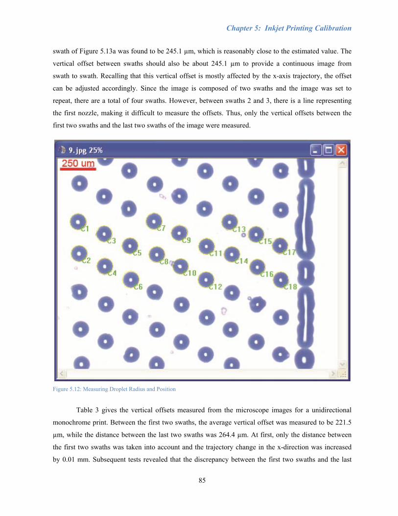
Chapter 5: Inkjet Printing Calibration
85
swath of Figure 5.13a was found to be 245.1 µm, which is reasonably close to the estimated value. The
vertical offset between swaths should also be about 245.1 µm to provide a continuous image from
swath to swath. Recalling that this vertical offset is mostly affected by the x-axis trajectory, the offset
can be adjusted accordingly. Since the image is composed of two swaths and the image was set to
repeat, there are a total of four swaths. However, between swaths 2 and 3, there is a line representing
the first nozzle, making it difficult to measure the offsets. Thus, only the vertical offsets between the
first two swaths and the last two swaths of the image were measured.
Figure 5.12: Measuring Droplet Radius and Position
Table 3 gives the vertical offsets measured from the microscope images for a unidirectional
monochrome print. Between the first two swaths, the average vertical offset was measured to be 221.5
µm, while the distance between the last two swaths was 264.4 µm. At first, only the distance between
the first two swaths was taken into account and the trajectory change in the x-direction was increased
by 0.01 mm. Subsequent tests revealed that the discrepancy between the first two swaths and the last
Chapter 5: Inkjet Printing Calibration
86
two swaths remained. It was then concluded that the low values from the first to second swaths could be
caused by motor backlash. As the printheads always return to home position at the end of a print, the
gears must reverse direction from the first swath to the second swath at the start of the next print job. As
a temporary solution, the x-axes were manually jogged forward in Control Desk before starting to print.
The trajectory was later changed to retract past the home position at the end of a print before moving
forward to zero.
At this point, it was realised that the printheads were still angled out of alignment and were
consequently realigned. This may have been a result of printing slightly more than 1.0 mm above the
substrate due to a miscalculation in homing position. However, the same alignment process was
followed and afterward, the swath width was changed from 10.41 mm to 10.42 mm to compensate for
the vertical offset between swaths. Looking at the new results after fine-tuning the alignment, the
difference of 3.494 µm between the average vertical offset for swaths 1 to 2 and the average vertical
offset for swaths 3 to 4 is reasonable considering the amount of measurement error.
Table 3: Vertical Offset Measurements
Between Two Dots Within a Swath [µm]
Before Fine-tuning Alignment After Fine-tuning Alignment Between
Swath 1 and Swath 2 [µm]
Between Swath 3 and
Swath 4 [µm]
Between Swath 1 and
Swath 2 [µm]
Between Swath 3 and
Swath 4 [µm] Average 245.1250 221.4844 264.4398 240.3494 236.8553
Maximum 257.2617 242.3910 274.5937 251.2971 257.1343 Minimum 231.2729 216.6836 249.0882 223.2748 217.5752
Figure 5.13a shows the image for the unidirectional multi-swath results. The measured
horizontal offsets can be found in Table 4. The horizontal offset is slightly worse between swaths 3 and
4. Considering the accuracy of the loop-shaping controller is within +/- 28 µm, as shown in Section 4.3,
it was determined that the accuracy of droplet placement was reasonable. An error of ±20.2 µm in
addition to the estimated ±3 µm of measurement error corresponds to around 40.6% of the average
droplet diameter of 57.19 µm or 28.3% of the 82 µm dot separation for 309 DPI.
Table 4: Horizontal Offsets for Unidirectional Printing Swaths 1-2 [µm] Swaths 3-4 [µm]
Average 9.541611 37.2616 Maximum 23.503 53.0452 Minimum 1.8079 16.184
Given the difficulty in adjusting the vertical offset discussed earlier, testing was also done at
1.5 mm above the substrate and 0.5 mm above the substrate as shown in Figure 5.13b and Figure 5.13c

Chapter 5: Inkjet Printing Calibration
87
to determine how printing at heights other than 1 mm would affect the results. The 1.5 mm gap showed
significantly worse positioning accuracy such that the entire image appears slanted, while the 0.5 mm
spacing increased the chances of smearing the print as the bottom plate or dust particles touched the
surface. Both the 0.5 mm and 1.5 mm clearances produced droplets of slightly smaller radius than at the
standard clearance [Table 5]. This could indicate that 1.0 mm is the optimal clearance, though the
varying droplet size could also be due to other factors, such as settling time or measurement error.
Nevertheless, these results show that a smaller substrate clearance is preferable to a larger one.
Table 5: Droplet Radius [µm] Comparison for Different Substrate Clearances 1.0 mm Above 0.5 mm Above 1.5 mm Above
Average 56.74776 55.9422 54.64355 Maximum 59.66048 58.4396 56.64148 Minimum 52.4289 53.9443 52.14613
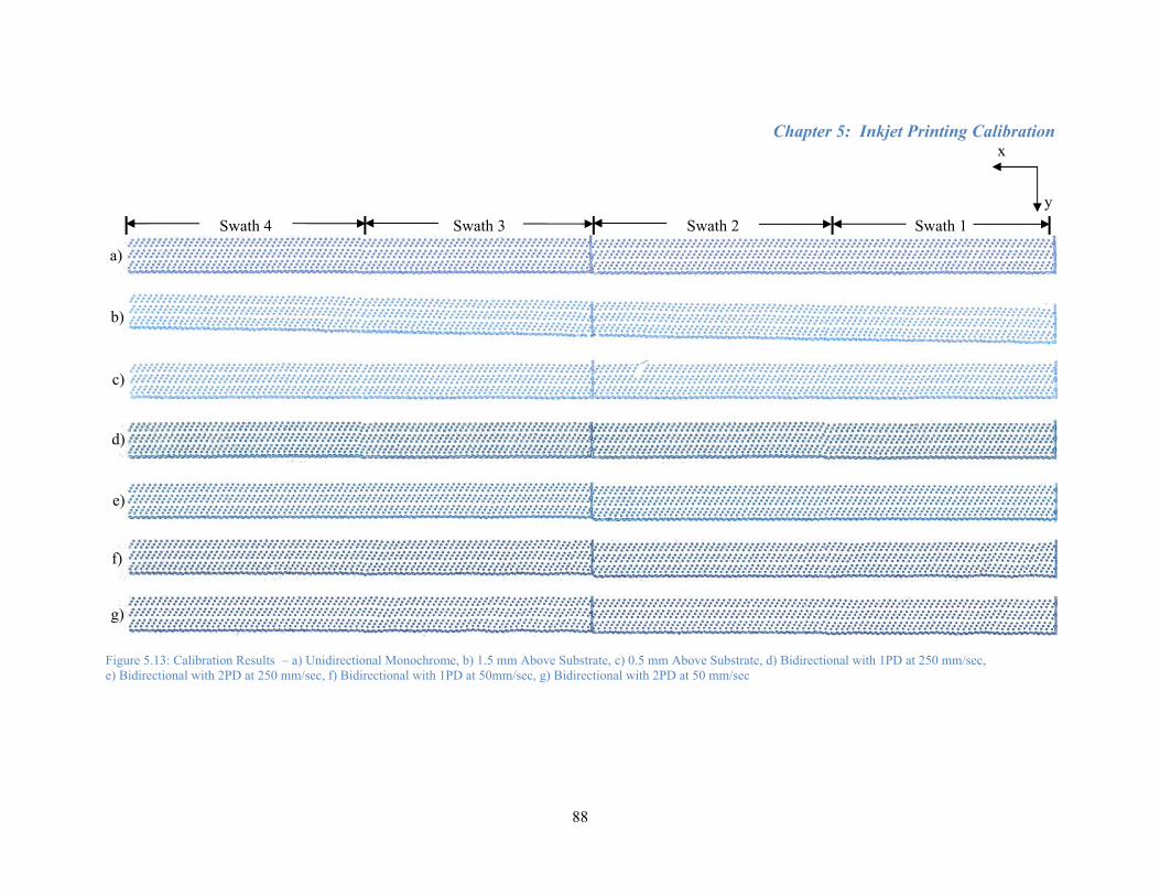
Chapter 5: Inkjet Printing Calibration
88
Swath 4 Swath 3 Swath 2 Swath 1
Figure 5.13: Calibration Results – a) Unidirectional Monochrome, b) 1.5 mm Above Substrate, c) 0.5 mm Above Substrate, d) Bidirectional with 1PD at 250 mm/sec, e) Bidirectional with 2PD at 250 mm/sec, f) Bidirectional with 1PD at 50mm/sec, g) Bidirectional with 2PD at 50 mm/sec
x
y
a)
b)
c)
d)
e)
f)
g)

Chapter 5: Inkjet Printing Calibration
89
Section 5.2.4: Unidirectional Multi-swath Multi-colour Printing
A verification of all the steps taken until this point would be to print a large, multicolour image
to show that all the colours are aligned individually and with each other. The original photograph in
Figure 5.14 was taken with a digital camera, courtesy of Ivan Chin. This test image was arbitrarily
chosen based on its range of colour composition and complex feature detail. Though it is more difficult
to differentiate each colour in a photograph, it will provide proof of concept. Figure 5.15 shows the full-
scale scanned image of the actual print on Xerox paper. The high droplet density causes the colours to
be much darker than the original image.

Chapter 5: Inkjet Printing Calibration
90
Figure 5.14: Unidirectional Multi-swath Multi-colour Test Image - Courtesy of Ivan Chin (1:1 scale)

Chapter 5: Inkjet Printing Calibration
91
Figure 5.15: Scan of Unidirectional Multi-swath Multi-colour Image Printed on Xerox Paper - Darker and less clear than original photograph (1:1 scale)
y
x
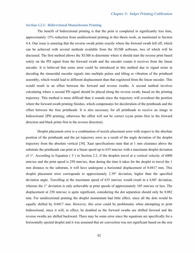
Chapter 5: Inkjet Printing Calibration
92
Section 5.2.5: Bidirectional Monochrome Printing
The benefit of bidirectional printing is that the print is completed in significantly less time,
approximately 15% reduction from unidirectional printing in this thesis work, as mentioned in Section
4.4. One issue is ensuring that the reverse swath prints exactly where the forward swath left off, which
can be achieved with several methods available from the XUSB software, two of which will be
discussed. The first method allows the XUSB to determine where it should start the reverse print based
solely on the PD signal from the forward swath and the encoder counts it receives from the linear
encoder. It is believed that some error could be introduced in this method due to signal noise in
decoding the sinusoidal encoder signals into multiple pulses and tilting or vibration of the printhead
assembly, which would lead to different displacement than that registered from the linear encoder. This
would result in an offset between the forward and reverse swaths. A second method involves
calculating where a second PD signal should be placed along the reverse swath, based on the printing
trajectory. This method is more difficult than it sounds since the trajectory will overshoot the position
where the forward swath printing finishes, which compensates for deceleration of the printheads and the
offset between the four printheads. It is also necessary for all printheads to receive an image in
bidirectional 2PD printing; otherwise the offset will not be correct (cyan prints first in the forward
direction and black prints first in the reverse direction).
Droplet placement error is a combination of nozzle placement error with respect to the absolute
position of the printheads and the jet trajectory error as a result of the angle deviation of the droplet
trajectory from the absolute vertical [38]. Xaar specifications state that at 1 mm clearance above the
substrate the printheads can print at a linear speed up to 635 mm/sec with a maximum droplet deviation
of 1°. According to Equation ( 5 ) in Section 2.2, if the droplets travel at a vertical velocity of 6000
mm/sec and the print speed is 250 mm/sec, then during the time it takes for the droplet to travel the 1
mm distance to the substrate, it will have undergone a horizontal displacement of 0.0417 mm. This
droplet placement error corresponds to approximately 2.39° deviation, higher than the specified
deviation angle. Travelling at the maximum speed of 635 mm/sec would result in a 6.04° deviation,
whereas the 1° deviation is only achievable at print speeds of approximately 105 mm/sec or less. The
displacement at 250 mm/sec is quite significant, considering the dot separation should only be 0.082
mm. For unidirectional printing the droplet momentum had little effect, since all the dots would be
equally shifted by 0.0417 mm. However, this error could be problematic when attempting to print
bidirectional, since it will, in effect, be doubled as the forward swaths are shifted forward and the
reverse swaths are shifted backward. There may be some error since the equations are specifically for a
horizontally ejected droplet and it was assumed that air convection was not significant based on the size
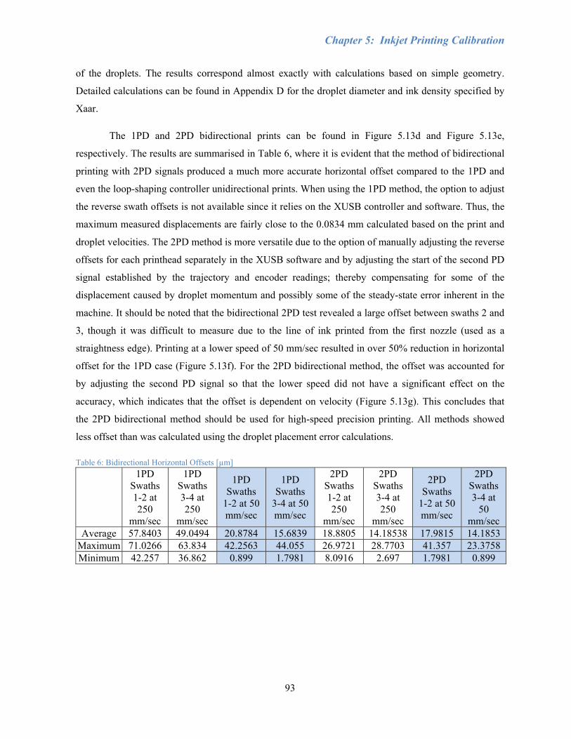
Chapter 5: Inkjet Printing Calibration
93
of the droplets. The results correspond almost exactly with calculations based on simple geometry.
Detailed calculations can be found in Appendix D for the droplet diameter and ink density specified by
Xaar.
The 1PD and 2PD bidirectional prints can be found in Figure 5.13d and Figure 5.13e,
respectively. The results are summarised in Table 6, where it is evident that the method of bidirectional
printing with 2PD signals produced a much more accurate horizontal offset compared to the 1PD and
even the loop-shaping controller unidirectional prints. When using the 1PD method, the option to adjust
the reverse swath offsets is not available since it relies on the XUSB controller and software. Thus, the
maximum measured displacements are fairly close to the 0.0834 mm calculated based on the print and
droplet velocities. The 2PD method is more versatile due to the option of manually adjusting the reverse
offsets for each printhead separately in the XUSB software and by adjusting the start of the second PD
signal established by the trajectory and encoder readings; thereby compensating for some of the
displacement caused by droplet momentum and possibly some of the steady-state error inherent in the
machine. It should be noted that the bidirectional 2PD test revealed a large offset between swaths 2 and
3, though it was difficult to measure due to the line of ink printed from the first nozzle (used as a
straightness edge). Printing at a lower speed of 50 mm/sec resulted in over 50% reduction in horizontal
offset for the 1PD case (Figure 5.13f). For the 2PD bidirectional method, the offset was accounted for
by adjusting the second PD signal so that the lower speed did not have a significant effect on the
accuracy, which indicates that the offset is dependent on velocity (Figure 5.13g). This concludes that
the 2PD bidirectional method should be used for high-speed precision printing. All methods showed
less offset than was calculated using the droplet placement error calculations.
Table 6: Bidirectional Horizontal Offsets [µm] 1PD
Swaths 1-2 at 250
mm/sec
1PD Swaths 3-4 at 250
mm/sec
1PD Swaths
1-2 at 50 mm/sec
1PD Swaths
3-4 at 50 mm/sec
2PD Swaths 1-2 at 250
mm/sec
2PD Swaths 3-4 at 250
mm/sec
2PD Swaths
1-2 at 50 mm/sec
2PD Swaths 3-4 at
50 mm/sec
Average 57.8403 49.0494 20.8784 15.6839 18.8805 14.18538 17.9815 14.1853 Maximum 71.0266 63.834 42.2563 44.055 26.9721 28.7703 41.357 23.3758 Minimum 42.257 36.862 0.899 1.7981 8.0916 2.697 1.7981 0.899

Chapter 5: Inkjet Printing Calibration
94
Section 5.2.6: Bidirectional Multi-colour Printing
Theoretically, multi-colour bidirectional printing should operate similarly to monochrome
bidirectional printing. However, another problem discovered with bidirectional printing is that the
printheads will print in a specific order pre-determined by their positions on the mounting plate. Based
on this single row setup, Cyan will print first and then Magenta will print on top of Cyan, followed by
Yellow, and then Black. However, in the reverse direction the printheads will print in the opposite
order, starting with Black, then Magenta, then Yellow, and then Cyan on top. The result is a slightly
different overall colour for the reverse swath than would be found in the forward direction, and occurs
both for images where the same image is sent to each colour and for images where the colours have
been properly separated in Photoshop. Upon close inspection of Figure 5.16, there is a noticeable
striping pattern of light (KYMC) and dark (CMYK) swaths. In this figure the first swath is actually a
KYMC pass. Since there are an odd number of swaths, a blank swath was inserted at the top of the
image. The striping is less apparent in the whiter areas of the image since the droplet density is
significantly lower and there are fewer overlapping colours. Due to this colour disparity, it is believed
that commercial printers typically print single-colour images in bidirectional, while multi-colour prints
are printed in unidirectional, based on the smaller length of time needed to complete a monochrome
image versus a multicolour image. The problem of colour disparity can be solved by having another set
of CMYK printheads in the opposite order alongside the original printheads, either on the same swath
or on a separate swath, so that one set will only print in the forward direction, and the other set will only
print in the reverse direction. However, this method would be costly to implement and may not be
possible using the XUSB software.

Chapter 5: Inkjet Printing Calibration
95
Figure 5.16: Scan of Colour Disparity in Bidirectional Printing - Dark swaths represent ink deposited in the order of CMYK and light swaths represent ink deposited in the order of KYMC (1:1 scale).
y
x
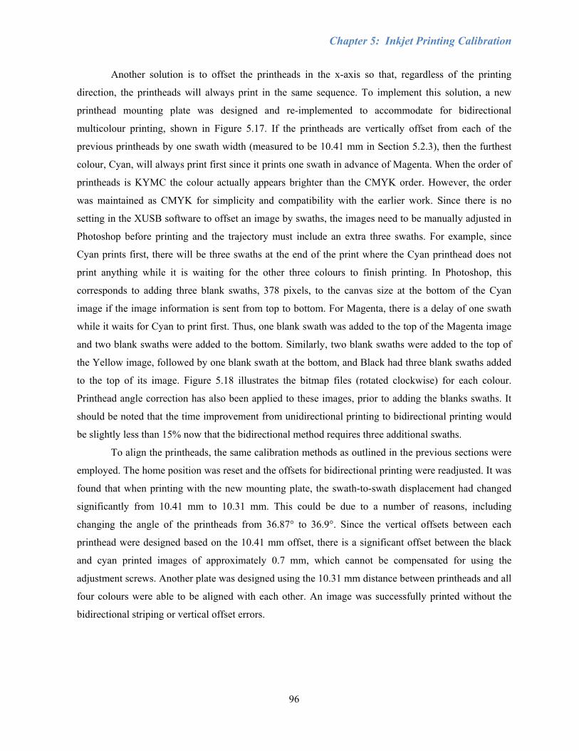
Chapter 5: Inkjet Printing Calibration
96
Another solution is to offset the printheads in the x-axis so that, regardless of the printing
direction, the printheads will always print in the same sequence. To implement this solution, a new
printhead mounting plate was designed and re-implemented to accommodate for bidirectional
multicolour printing, shown in Figure 5.17. If the printheads are vertically offset from each of the
previous printheads by one swath width (measured to be 10.41 mm in Section 5.2.3), then the furthest
colour, Cyan, will always print first since it prints one swath in advance of Magenta. When the order of
printheads is KYMC the colour actually appears brighter than the CMYK order. However, the order
was maintained as CMYK for simplicity and compatibility with the earlier work. Since there is no
setting in the XUSB software to offset an image by swaths, the images need to be manually adjusted in
Photoshop before printing and the trajectory must include an extra three swaths. For example, since
Cyan prints first, there will be three swaths at the end of the print where the Cyan printhead does not
print anything while it is waiting for the other three colours to finish printing. In Photoshop, this
corresponds to adding three blank swaths, 378 pixels, to the canvas size at the bottom of the Cyan
image if the image information is sent from top to bottom. For Magenta, there is a delay of one swath
while it waits for Cyan to print first. Thus, one blank swath was added to the top of the Magenta image
and two blank swaths were added to the bottom. Similarly, two blank swaths were added to the top of
the Yellow image, followed by one blank swath at the bottom, and Black had three blank swaths added
to the top of its image. Figure 5.18 illustrates the bitmap files (rotated clockwise) for each colour.
Printhead angle correction has also been applied to these images, prior to adding the blanks swaths. It
should be noted that the time improvement from unidirectional printing to bidirectional printing would
be slightly less than 15% now that the bidirectional method requires three additional swaths.
To align the printheads, the same calibration methods as outlined in the previous sections were
employed. The home position was reset and the offsets for bidirectional printing were readjusted. It was
found that when printing with the new mounting plate, the swath-to-swath displacement had changed
significantly from 10.41 mm to 10.31 mm. This could be due to a number of reasons, including
changing the angle of the printheads from 36.87° to 36.9°. Since the vertical offsets between each
printhead were designed based on the 10.41 mm offset, there is a significant offset between the black
and cyan printed images of approximately 0.7 mm, which cannot be compensated for using the
adjustment screws. Another plate was designed using the 10.31 mm distance between printheads and all
four colours were able to be aligned with each other. An image was successfully printed without the
bidirectional striping or vertical offset errors.
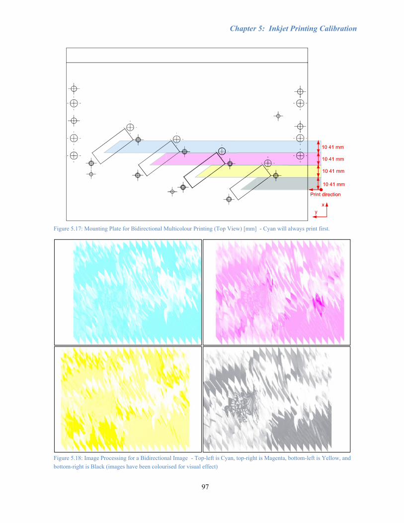
Chapter 5: Inkjet Printing Calibration
97
Figure 5.17: Mounting Plate for Bidirectional Multicolour Printing (Top View) [mm] - Cyan will always print first.
Figure 5.18: Image Processing for a Bidirectional Image - Top-left is Cyan, top-right is Magenta, bottom-left is Yellow, and bottom-right is Black (images have been colourised for visual effect)
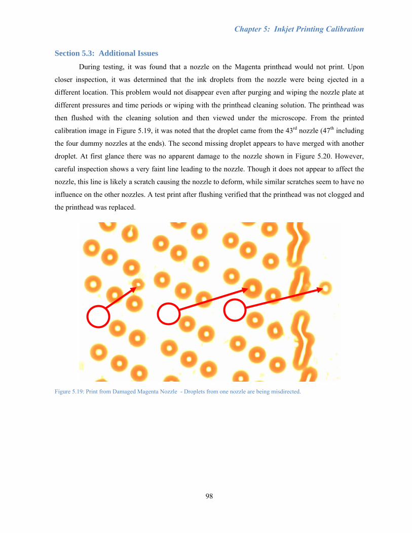
Chapter 5: Inkjet Printing Calibration
98
Section 5.3: Additional Issues
During testing, it was found that a nozzle on the Magenta printhead would not print. Upon
closer inspection, it was determined that the ink droplets from the nozzle were being ejected in a
different location. This problem would not disappear even after purging and wiping the nozzle plate at
different pressures and time periods or wiping with the printhead cleaning solution. The printhead was
then flushed with the cleaning solution and then viewed under the microscope. From the printed
calibration image in Figure 5.19, it was noted that the droplet came from the 43rd nozzle (47th including
the four dummy nozzles at the ends). The second missing droplet appears to have merged with another
droplet. At first glance there was no apparent damage to the nozzle shown in Figure 5.20. However,
careful inspection shows a very faint line leading to the nozzle. Though it does not appear to affect the
nozzle, this line is likely a scratch causing the nozzle to deform, while similar scratches seem to have no
influence on the other nozzles. A test print after flushing verified that the printhead was not clogged and
the printhead was replaced.
Figure 5.19: Print from Damaged Magenta Nozzle - Droplets from one nozzle are being misdirected.

Chapter 5: Inkjet Printing Calibration
99
Figure 5.20: Damaged Nozzle on Magenta Printhead - Malfunctioning nozzle is likely due to a faint scratch.
Another issue found was that the printheads were prone to leak when the system was turned off
for long periods of time. Though each component was examined carefully, the leakage was possibly
caused by air gaps or cracks in fittings, dysfunctional printheads, malfunctioning header tank pressure
sensors, or insufficient negative pressure to maintain ink meniscus. On one occasion, a header tank was
believed to have failed. After printing for a variable period of time the printhead would continue to leak
almost as much as when the vacuum is not being applied and the manual valve is open. When the
manual valve was closed, the ink would slowly move toward the ink trap bottle and vacuum as when
there is too much pressure applied. Once the pressure stabilised after the system had been turned off
overnight, the printhead would print several images normally and then suddenly start to leak again.
Since then the issue has not occurred and may have been due to overdriving the printhead while testing
various settings. A replacement header tank should be ordered in case the problem has not been
resolved.
Chapter 5: Inkjet Printing Calibration
100
Section 5.4: Conclusions
This chapter described the process and issues involved in calibrating Xaar 126 printheads, as
well as characterising the droplet placement accuracy. The precision of droplet placement is very
important in generating a quality image, and even more so for future MEMS and nanotechnology
applications. There are many factors which influence the accuracy of the printheads including droplet
firing speed, print speed, printhead orientation, and precise motion tracking. Printhead orientation was
adjusted mechanically using fine thread screws or through software offsets. PD signals, trajectory
generation, and motion control influenced the overall swath offsets. Calibration images were printed on
high gloss HP photo paper to reduce droplet distortion and measurement error, while pictures were
printed on Xerox inkjet paper for optimal absorption and minimal bleeding. The calibration images
were used to align the printheads and were viewed under a microscope at 50x magnification and
analysed using ImagePro software for droplet size and relative position. The horizontal resolution of the
printheads is inherently worse than the vertical resolution due to the frequency of nozzle firing in the
piezoelectric shear mode design. Thus measurements were only made within nozzles of the same group.
The system was tested and calibrated systematically by adding one element of complexity at a
time to determine the accuracy and capability of the printheads. These main modes were single colour
unidirectional, multicolour unidirectional, single colour bidirectional, and multicolour bidirectional
printing. Bidirectional tests were further divided into different speeds and whether one or two PD
signals were generated. Monochrome unidirectional printing provided the basis for the swath angle,
which was found to be roughly 90°±1°. Multicolour unidirectional printing evaluated how well each
colour aligned with each other both vertically and horizontally. From the unidirectional results, the
vertical swath-to-swath displacement was corrected to 10.42 mm. It was also shown that printing
clearances higher than 1 mm significantly reduced the quality of the print. Smaller clearances may be
possible at an increased risk of smearing either the print before it absorbs into the substrate or any ink
found on the bottom of the plate or the printhead nozzles, depending on the surface finish of the
substrate. Bidirectional printing reduced print time with little increase in horizontal offset between
swaths. For high-speed printing accuracy, generating 2PD signals produced much better results than the
1PD option. A new printhead mounting plate was designed where the printheads were offset vertically
from each other by one swath width to eliminate the colour striping problem resulting from switching
the order in which the colours were deposited during bidirectional printing. This solution required
additional image processing of adding blank swaths to the beginning and ending of each image
corresponding to the printhead position on the plate. Bidirectional colour printing was achieved at the
maximum speed of the router (250 mm/sec) with comparable accuracy to unidirectional printing.
101
Chapter 6: Printing on Different Media To prove the integration of printing and cutting for sign and furniture industries, it was
necessary to show the capability of printing on substrates such as wood. Cutting, or engraving, which
would follow the printing process, has already been researched on the router and so will not be
investigated further in this thesis. As discussed in the previous chapters, the main factor in printing high
quality images is precise droplet placement. In order to print on materials such as wood and improve the
colour appearance, ink jet printers generally require a special pre-coating to help the ink cure and
prevent bleeding. Most satisfactory results on wood in industry have been achieved using water-based
inks. However, the ink used in this thesis is oil-based, which relies mainly on direct absorption into the
substrate and is intended for paper rather than wood. As the ink tends to absorb into the grain of the
substrate, different types of wood and coatings were tested to find the optimal conditions for a high
quality image.
Hymmen uses three major steps for direct printing on wood: preparation of the substrate,
preparation of printing base, and sealing of the surface. The surface of the substrate should be clean and
is prepared by sanding, filling, and smoothing, depending on the substrate material. For particle boards
there is usually a section for a water-based filler and a section for a UV-filler, followed by drying. MDF
requires a water-based primer to prepare for adhesion of the filler and just one section for filling and
drying. Next, two to three base coats are applied, each followed by a dryer, and then two or more
printing machines. Sealing consists of two layers of UV-lacquer with subsequent curing; corundum
particles are added to lacquer layers for abrasion protection. This process developed by Hymmen was
not found until later in this research. However, a few steps could be applied to the initial case studies
found in this section, such as preparing the MDF with an oil-based primer, sanding, applying an oil-
based filler, and an oil-based base coat before printing the image. [1]
This chapter will present the results from printing on different types of wood and coatings. A
walnut wood pattern was chosen to simulate the effect of manufacturing furniture or flooring with
inexpensive materials. The original image can be found in Figure 6.1, with the actual size of the image
being 211.67 mm x 159.3 mm. A darker image such as this one was preferred in order to test the limits
of the system, since the lower density of ink in lighter images makes them more easily adaptable to
different substrates. Conclusions are provided in Section 5.4.
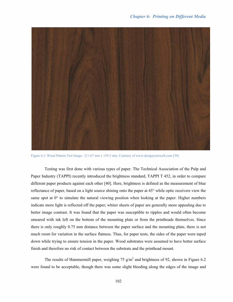
Chapter 6: Printing on Different Media
102
Figure 6.1: Wood Pattern Test Image - 211.67 mm x 159.3 mm. Courtesy of www.designyourwall.com [39]
Testing was first done with various types of paper. The Technical Association of the Pulp and
Paper Industry (TAPPI) recently introduced the brightness standard, TAPPI T 452, in order to compare
different paper products against each other [40]. Here, brightness is defined as the measurement of blue
reflectance of paper, based on a light source shining onto the paper at 45° while optic receivers view the
same spot at 0° to simulate the natural viewing position when looking at the paper. Higher numbers
indicate more light is reflected off the paper; whiter sheets of paper are generally more appealing due to
better image contrast. It was found that the paper was susceptible to ripples and would often become
smeared with ink left on the bottom of the mounting plate or from the printheads themselves. Since
there is only roughly 0.75 mm distance between the paper surface and the mounting plate, there is not
much room for variation in the surface flatness. Thus, for paper tests, the sides of the paper were taped
down while trying to ensure tension in the paper. Wood substrates were assumed to have better surface
finish and therefore no risk of contact between the substrate and the printhead mount.
The results of Hammermill paper, weighing 75 g/m2 and brightness of 92, shown in Figure 6.2
were found to be acceptable, though there was some slight bleeding along the edges of the image and

Chapter 6: Printing on Different Media
103
the image colour was much darker than the original image. Xerox inkjet paper, 90 g/m2 and brightness
of 92 was found to have less bleeding along the edges and brighter colour, as seen in Figure 6.3. The
heavier Xerox paper was likely able to handle a heavier application of ink than the Hammermill paper,
which is more suitable for high-volume printing. Both were still unacceptable in terms of calibration as
the droplets would absorb into the fibres of the paper, making it difficult to determine the exact size and
location of droplet deposition. HP high-gloss paper, weighing 280 g/m2, was also tested with a
calibration image, though the oil-based ink provided by Xaar would not absorb into the HP paper even
after a long period of time. However, this also allowed the ink droplets to be highly visible, since the
droplets were not distorted by the fibres in the paper, as in the Xerox inkjet paper. Calibration tests were
thus printed on glossy paper and viewed under a microscope, as demonstrated in Chapter 5.
MDF is made out of wood waste fibres glued together with resin by heat and pressure, and has
been shown to be readily milled into parts depending on feed parameters, cutting tool, and workpiece
quality. The low cost of MDF makes it an ideal choice for the sign and furniture industries and was thus
one of the main test materials. Each layer in an MDF panel has an effect on the final surface roughness,
which is a factor in how well ink droplets are placed [41]. As shown in Figure 6.4, printing directly on
MDF showed more bleeding than on paper, causing the image to appear much darker and losing sharp
details, despite the image being significantly lightened in Photoshop. The non-paper images may be
distorted as a result of the digital camera viewing angle. Various coatings were also tested that did not
absorb the ink very well, taking several days for the ink to dry. Coatings that were manually applied
were painted with a fine latex brush and allowed to dry according to their respective instructions. Figure
6.5 shows MDF coated with semi-gloss varnish, which allowed the colours to bleed together to form an
incoherent image. A double coat of rust paint on MDF produced a dark image with heavy bleeding in
Figure 6.6.
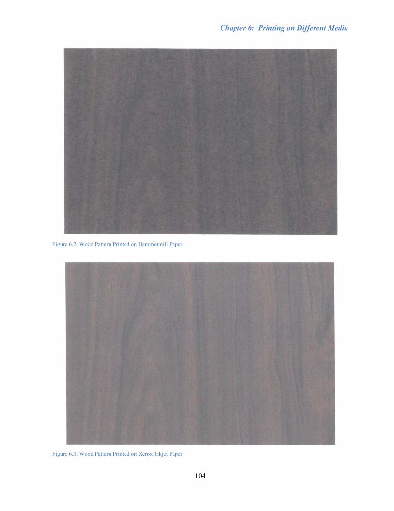
Chapter 6: Printing on Different Media
104
Figure 6.2: Wood Pattern Printed on Hammermill Paper
Figure 6.3: Wood Pattern Printed on Xerox Inkjet Paper
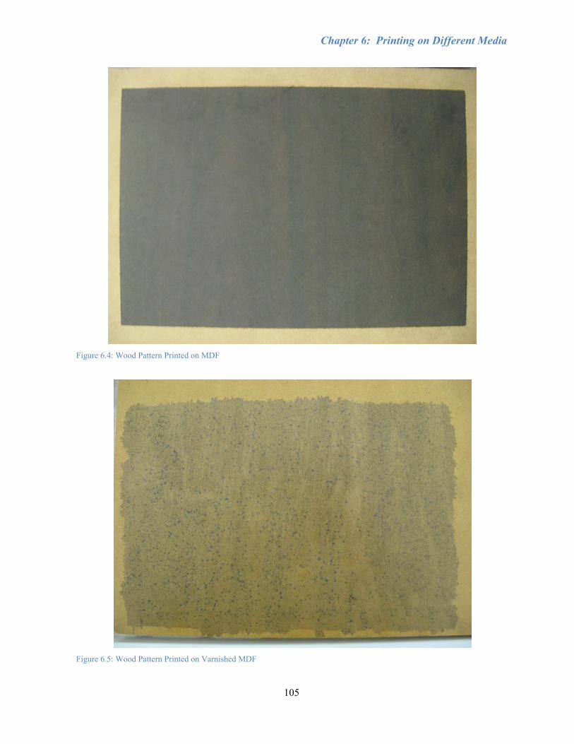
Chapter 6: Printing on Different Media
105
Figure 6.4: Wood Pattern Printed on MDF
Figure 6.5: Wood Pattern Printed on Varnished MDF

Chapter 6: Printing on Different Media
106
Figure 6.6: Wood Pattern Printed on MDF Painted with Rust Paint
Other inexpensive building materials such as drywall were also tested. Subsequently, as seen in
Figure 6.7, printing directly on drywall produced results close to paper, though slightly darker due to
the greyish hue of the drywall. However, drywall is typically coated with a primer to seal it from water
and thus, printing directly on drywall would not be reasonable. Drywall painted with a double-coat of
primer resulted in a dark image worse than plain MDF, losing much of the sharper details due to colour
bleeding (Figure 6.8). Plywood was then tested and resulted in the ink absorbing into the grain of the
wood such that the image details were very poor, taking on the appearance of the plywood rather than
the walnut image (Figure 6.9). Next, MDF pre-coated with a white paint, likely oven-baked, was
purchased from a public consumer store. The result was an image close to the original image, though
the colour was slightly washed out and the cracks in the coating could be seen through the image when
viewed within roughly 1 m (Figure 6.10). The abnormal coloured swath on the right is thought to be a
consequence of electrical noise interfering with the yellow printhead. It is believed that the cracks are a
result of the oven-baking process and possibly a spray-painted version could be found that would create
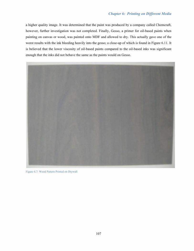
Chapter 6: Printing on Different Media
107
a higher quality image. It was determined that the paint was produced by a company called Chemcraft,
however, further investigation was not completed. Finally, Gesso, a primer for oil-based paints when
painting on canvas or wood, was painted onto MDF and allowed to dry. This actually gave one of the
worst results with the ink bleeding heavily into the gesso; a close-up of which is found in Figure 6.11. It
is believed that the lower viscosity of oil-based paints compared to the oil-based inks was significant
enough that the inks did not behave the same as the paints would on Gesso.
Figure 6.7: Wood Pattern Printed on Drywall
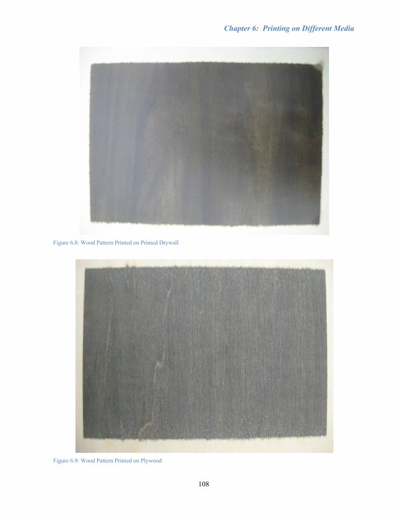
Chapter 6: Printing on Different Media
108
Figure 6.8: Wood Pattern Printed on Primed Drywall
Figure 6.9: Wood Pattern Printed on Plywood
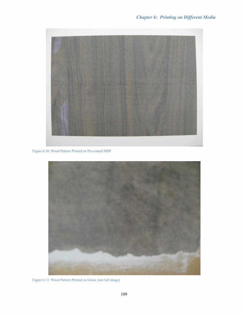
Chapter 6: Printing on Different Media
109
Figure 6.10: Wood Pattern Printed on Pre-coated MDF
Figure 6.11: Wood Pattern Printed on Gesso (not full image)
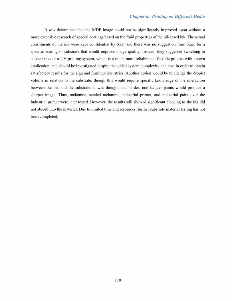
Chapter 6: Printing on Different Media
110
It was determined that the MDF image could not be significantly improved upon without a
more extensive research of special coatings based on the fluid properties of the oil-based ink. The actual
constituents of the ink were kept confidential by Xaar and there was no suggestion from Xaar for a
specific coating or substrate that would improve image quality. Instead, they suggested switching to
solvent inks or a UV printing system, which is a much more reliable and flexible process with known
application, and should be investigated despite the added system complexity and cost in order to obtain
satisfactory results for the sign and furniture industries. Another option would be to change the droplet
volume in relation to the substrate, though this would require specific knowledge of the interaction
between the ink and the substrate. It was thought that harder, non-lacquer paints would produce a
sharper image. Thus, melamine, sanded melamine, industrial primer, and industrial paint over the
industrial primer were later tested. However, the results still showed significant bleeding as the ink did
not absorb into the material. Due to limited time and resources, further substrate material testing has not
been completed.

Chapter 6: Printing on Different Media
111
Section 6.1: Conclusions
Oil-based ink produced the best images on Xerox inkjet paper, with almost no bleeding and
high resolution. Since the oil-based ink did not absorb into the HP high-gloss photo paper, the droplets
could be clearly seen as close as possible to the original image size and position, as shown in the
previous chapter. The best results on wood were achieved by printing directly onto MDF or MDF pre-
coated by an oven-baked white paint. However, the image on unfinished MDF was significantly darker
than on paper and had to be drastically lightened in Photoshop before printing. There was also some
noticeable bleeding into the MDF grain. The image on the pre-coated MDF allowed the cracks in the
paint to show through the ink when viewed at close range and also required a much longer drying time
than for plain paper or MDF. If the correct coating could be found that absorbs oil-based ink with
minimal bleeding, then any substrate that is compatible with the coating could be first coated then
printed with the desired image. Image quality on wood could be significantly improved with the use of
UV-inks, which have been shown in industry to provide better quality, minimal colour bleeding, and
reasonable durability even in outdoor conditions. An alternate approach would be to vary the dot size
based on the substrate, though a more in depth knowledge of the printhead waveforms and interaction
between ink and substrate would be necessary.
112
Chapter 7: Conclusions and Recommendations This thesis has presented the integration of an inkjet printing system onto a low-grade,
industrial flatbed router. The benefits of such a combined printing and cutting system include reduced
waste, faster operation, and it provides the potential for applications outside of paper products, such as
the manufacture of signs, furniture, and laminate flooring.
The Xaar 126 printing system was chosen as the introductory tool for learning about the
printing process due to its ease of assembly, low cost compared to other systems, simple operation, and
potential for future applications with alternative inks. All necessary electrical, mechanical, and software
connections were made to allow communication between the computer and printing components, while
adhering to the structure of the existing router. A secondary z-axis was designed and assembled
alongside the existing spindle axis in order to actuate the printheads over substrates of variable
thickness. For any future work, the mechanical assembly between the printhead mount and the spindle
should be minimised for increased work area.
A loop-shaping controller was designed based on the frequency response of the machine to
account for the resonant and high frequency dynamics of the servo system in the y-axis, which is the
main motion contributing to droplet placement accuracy and is particularly important for bidirectional
printing, as well as subsequent milling operations. The loop-shaping controller showed a 75%
improvement in tracking error over the Sliding Mode Controller and 79% improvement over the
industrial benchmark. A homing routine was developed for the secondary z-axis and an interface was
made in Control Desk in order to position the printheads where desired before starting to print.
Consistently starting in the same position is necessary since the thickness of the substrate may change
and a 1 mm clearance between the printheads and the substrate must be maintained for quality image
results. Homing routines should also be developed for the x- and y-axes, similar to that of the secondary
z-axis. Smooth, jerk-limited trajectories were used to diminish the influence of vibrations on the
printheads. It is likely that the dSPACE memory will overrun due to the long trajectories necessary for
larger images. Further investigation should be made to create a buffer as is applied in typical printers so
that only small sections of the image are sent to the printheads at a time and the back and forth
trajectory can simply be repeated with an increase in x-position values. Alternate printing hardware
may be necessary since the XUSB only handles bitmaps or similar file types, which have a limit on
image size.
Alignment of the printheads is accomplished through mechanical and software means by the
adjustment screws holding the printhead in place relative to a thrust pin, offsets defined in the XUSB
Chapter 7: Conclusions and Recommendations
113
software, and the swath-to-swath displacement. Calibration images were printed onto high-gloss HP
paper and viewed under a microscope at 50x magnification to evaluate the accuracy of droplet
placement. One element of complexity was added at a time, first starting from a monochrome,
unidirectional image for the alignment of a single printhead, then aligning the rest of the printheads
with respect to the aligned printhead. Next, large images were tested to determine the swath-to-swath
accuracy in terms of vertical and horizontal offsets, which are mostly controlled by the trajectory and
Product Detect signal, respectively, as well as positioning accuracy. Finally, bidirectional printing was
implemented using both 1PD and 2PD signals, where the 2PD method provided more reliable droplet
placement. A new mounting plate was designed to eliminate the bidirectional colour striping as a result
of alternating the order in which colours are deposited. This was accomplished by offsetting the
printheads from each other by one swath each so that they always print in a specific order. It is
necessary to add extra blank swaths to the images to compensate for these offsets. Bidirectional printing
was shown to be at least 15% faster than unidirectional printing, with comparable droplet placement
accuracy.
Various substrates were tested, with pre-coated MDF showing the best results in terms of
colour and resolution. It was difficult to achieve satisfactory results, since the ink absorbs into the
material, allowing the substrate grain to show through the image. Darker substrates also reduced the
colour quality of the image significantly, despite image processing in Photoshop. More testing should
be done with different substrate coatings or preparation to obtain better quality results. Much of the
image resolution is lost when converting from various file types to bitmap. Greyscale printheads would
improve the colour of the printed images since they can control the amount of ink that is being
deposited in order to produce more vibrant colours, corresponding more closely to the original digital
image. A white pre-coating should also be incorporated into the system to allow images to be printed on
any substrate without significant colour loss or colour compensation in Photoshop. In order to improve
the quality of print on MDF wood and other materials, a UV system should be installed onto the router.
This would require obtaining UV inks, UV-proof tubing, and a UV lamp. Changes to the system and/or
environment would need to be made to ensure that no external UV light reaches any ink, otherwise
undesirable curing will take place. In a UV system, colours can be cured one at a time or all at once,
depending on the strength of the UV light. Curing one colour at a time could cause over-curing and
cracking of the lower ink layers. Different curing intensities and durations would need to be adjusted to
prevent over-curing.
The final combined printing system was able to print on various paper and wood substrates
with calibration results showing droplet positioning errors of less than 4 µm in the vertical direction and

Chapter 7: Conclusions and Recommendations
114
less than 30 µm in the horizontal direction, using a 2PD bidirectional trajectory at the maximum drive
speed of 250 mm/sec. These results are significantly better than the 100 µm feed accuracy specified by
the printing systems currently manufactured by Zünd. The ideas developed in this thesis could also be
used to implement material deposition for applications such as manufacturing microchips, LEDs, and
3D printing and cutting. However, these technologies would require machines of higher positioning
accuracy than was presented in this thesis.

115
References
[1] Lentner, A., 2006. Direct Multi-Colour Printing on Wood and Wood Composite Panels, Decorative and Industrial Laminates Symposium, August 21-23 2006, Technical Association of the Pulp and Paper Industry pp1-15.
[2] Graedel, T.E. and Howard-Grenville, J.A., 2005. Forest Products and Printing. Greening the Industrial Facility. Springer US, pp. 369-387.
[3] Madou, M.J., 2002. Fundamentals of Microfabrication. 2 edn. CRC Press.
[4] Lee, E.R., 2003. Microdrop generation. Boca Raton, Fla.; London: CRC Press.
[5] Hon, K.K.B., Li, L. and Hutchings, I.M., 2008. Direct Writing Technology - Advances and Developments. Annals of the CIRP, 57.
[6] Wallace, D.B., 1989. Automated Electronic Circuit Manufacturing Using Ink-Jet Technology. Journal of Electronic Packaging, 111(2), 108-112.
[7] Bharathan, J. and Yang, Y., 1998. Polymer electroluminescent devices processed by inkjet printing: I. Polymer light-emitting logo. Applied Physics Letters, 72(21), 2660-2662.
[8] Dong, H., 2007. Improving Gantry Style Router Tracking Accuracy through Optical Linear Encoder Retrofit and Error Compensation Using Laser Interferometry. Work report. Waterloo, Ontario, University of Waterloo, Faculty of Engineering.
[9] Heng, M., 2008. Smooth and Time-Optimal Trajectory Generation for High Speed Machine Tools. Master's thesis. Waterloo, Ontario, University of Waterloo, Faculty of Engineering.
[10] Kamalzadeh, A., 2009. Precision Control of High Speed Ball Screw Drives, PhD thesis. Waterloo, Ontario, University of Waterloo, Faculty of Engineering.
[11] Le, H.P., 1999. Progress and Trends in Ink-jet Printing Technology. Recent Progress in Ink Jet Technologies II. Society for Imaging Science and Technology, pp. 1-14.
[12] Martin, G.D., Hoath, S.D. and Hutchings, I.M., 2008. Inkjet printing - the physics of manipulating liquid jets and drops, Engineering and Physics - Synergy for Success, 03/01 2008, IOP Publishing Ltd. pp1-14.
[13] Beurer, G. and Kretschmer, J., 1999. Function and Performance of a Shear Mode Piezo Printhead. Recent Progress in Ink Jet Technologies II. Society for Imaging Science and Technology, pp. 151-155.
[14] Heinzl, J., 2008. Ink Jets. Comprehensive Microsystems. Oxford: Elsevier, pp. 335-368.

Reference
116
[15] McConnell, J.J., 2006. Computer Graphics: Theory into Practice. Jones and Bartlett Publishers, Inc.
[16] Hancock, A. and Lin, L., 2004. Challenges of UV curable ink-jet printing inks - a formulator's perspective. Pigment and Resin Technology, , 280-286.
[17] Whitcher, J., 2006. Getting Wider. Graphic Arts Online, (6), pp. 14-19.
[18] Beeson, R., 1999. Thermal Inkjet: Meeting the Applications Challenge. Recent Progress in Ink Jet Technologies II. Society for Imaging Science and Technology, pp. 43-46.
[19] Schofield, J.D., 1999. Ink Systems for the Xaar Ink Jet Printhead. Recent Progress in Ink Jet Technologies II. Society for Imaging Science and Technology, pp. 430-434.
[20] Rioboo, R., Marengo, M. and Tropea, C., 2002. Time evolution of liquid drop impact onto solid, dry surfaces. Experiments in Fluids, 33(1), 112-24.
[21] Yarin, A.L., 2006. Drop Impact Dynamics: Splashing, Spreading, Receding, Bouncing... Annual Review of Fluid Mechanics, 38, 159-192.
[22] Marx, D., 2005. Flatbed inkjet expands printing possibilities. Canadian Printer, 113(5), 30-34.
[23] Zünd, 2010-last update, zünd - swiss cutting systems. Available: http://zund.com/ [March 2, 2010].
[24] Hymmen and Xaar, 2009. Jupiter Digital Printing Line News Release, LIGNA 2009, 18-22 May 2009.
[25] DPR laminate flooring from Egger. 2008. Lamniat-Magazin.
[26] Hymmen, 2009. Hymmen Develops own Digital Printing Technology.
[27] Mills, R.N. and Demyanovich, W.F., 2005. Materials and Process Development for Digital Fabrication Using Ink Jet Technology. Digital Fabrication, 1, 8-12.
[28] Xaar System Manual. 2008. Cambridge, UK: Xaar.
[29] Moon, A., 2008. Design and Installation of Inkjet Printing System on a Flatbed Router. Waterloo, Ontario: University of Waterloo, Faculty of Engineering.
[30] Heidenhain, 2007. Interface Electronics.
[31] Baqai, F.A., Lee, J.-., Agar, A.U. and Allebach, J.P., 2005. Digital color halftoning. IEEE Signal Processing Magazine, 22(1), 87-96.

Reference
117
[32] Anastassiou, D. and Pennington, K.S., 1982. Digital Halftoning of Images. 26, 687-697.
[33] Altintas, Y., Erkorkmaz, K. and Zhu, W.-., 2000. Sliding Mode Controller Design for High Speed Feed Drives. CIRP Annals - Manufacturing Technology, 49(1), 265-270.
[34] Franklin, G.F., Powell, J.D. and Emami-Naeini, A., 2009. Feedback Control of Dynamic Systems. 6 edn. Prentice Hall.
[35] Hofstetter, H.W., Griffin, J.R., Berman, M.S. and Everson, R.W., 2000. Dictionary of Visual Science and Related Clinical Terms. 5 edn. Butterworth-Heinemann.
[36] Brunahl, J. and Grishin, A.M., 2002. Piezoelectric shear mode drop-on-demand inkjet actuator. Sensors and Actuators A (Physical), A101(3), 371-82.
[37] Kretschmer, J. and Beurer, G., 1999. Design Parameters of a Shear Mode Piezo Printhead for a Given Resolution. Recent Progress in Ink Jet Technologies II. Society for Imaging Science and Technology, pp. 156-162.
[38] Wang, X., 2009. Piezoelectric Inkjet Technology - From Graphic Printing to Material Deposition, Nanotech Conference & Expo 2009, May 3 - 7 2009, Dimatix Fujifilm.
[39] Design Your Wall, 2010-last update, walnut self-stick wood grain wall contact paper [Homepage of Design Your Wall], [Online]. Available: www.designyourwall.com [April 5, 2010].
[40] Brightness of pulp, paper, and paperboard (directional reflectance at 457nm), Test Method T 452 om-08. 2009. Technical Association of Pulp and Paper Industry.
[41] Davim, J.P., Clemente, V.C. and Silva, S., 2009. Surface roughness aspects in milling MDF (medium density fibreboard). The International Journal of Advanced Manufacturing Technology, 40, 49-55.

118
Appendix A: Xaar Printhead Specifications
Active Nozzles 126 Nozzle Pitch [mm] 137.1
Nozzle Diameter [μm] 40 Typical Drop Volume [pl] 50 Typical Drop Velocity [m/s] 6.0 Max Drop Deviation [degrees] 1.0
Ambient Temperature Range [°C] 15 – 35 Ambient Humidity (non‐condensing) [%] 10 – 90 RH
Max Frequency [kHz] 7.5 Max Linear Speed (single pass) [mm/s] 635 Pixel Resolution, swathe x traverse [dpi] 300 x 300 Print Height at Given Resolution [mm] 10.6
Weight (dry) [g] 35 Dimensions (WxHxL) [mm] 43x11.8x45
Recommended Printing Distance [mm] 1 Internal Fluid Volume [ml] 2
Maximum Printhead Acceleration [m/s2] 9.81

119
Appendix B: Printhead Angle Calculations
DPI stated in XUSB software 309 Number of printhead nozzles, n 126
Swath Width, w [mm]:
3573.104.25126309
=×==inch
mmn
DPIw
Distance Between Nozzles, d [mm]:
0829.01126
3573.101
=−
=−
=n
wd
Distance from one swath to the next, δx, [mm]:
4401.103573.100829.0 =+=+= wdxδ
It can be seen that the swath width of 10.3 mm mentioned in the manual is not accurate.
The datasheet from the website gives the distance from the first nozzle to the last nozzle as 17.2 mm,
while the manual claims it is 17.1 mm.
Angle for distance of 17.2 mm [degrees]:
0253.372.17
4401.10sin2.17
sin 11 =⎟⎠⎞
⎜⎝⎛=⎟
⎠⎞
⎜⎝⎛= −− wθ
Angle for distance of 17.1 mm [degrees]:
2784.371.17
4401.10sin1.17
sin 11 =⎟⎠⎞
⎜⎝⎛=⎟
⎠⎞
⎜⎝⎛= −− wθ

Appendix B
120
The manual states that the printheads should be angled at 36.9° though it correlates this with 300 DPI
and 10.3 mm swath width, neither of which is accurate:
Angle, θ [degrees] 36.9 Distance from first to last nozzle [mm] 17.2
Swath Width, w [mm]:
( ) 3272.109.36sin2.17 ==w
DPI:
8992.3094.253272.10
126=×=DPI
Distance between nozzles, d [mm]:
0826.01253272.10
1==
−=
nwd
Distance from one swath to the next, δx, [mm]:
4098.103272.100826.0 =+=+= wdxδ
Angle, θ [degrees] 36.9 Distance from first to last nozzle [mm] 17.1
Swath Width, w [mm]:
( ) 2672.109.36sin1.17 ==w
DPI:
7115.3114.252672.10
126=×=DPI
Distance between nozzles, d [mm]:
0821.01252672.10
1==
−=
nwd
Distance from one swath to the next, δx, [mm]:
3493.102672.100821.0 =+=+= wdxδ

Appendix B
121
It was thought that the 36.9° was an approximation for the angle of a right triangle with side length
ratios 3-4-5.
Angle, θ [degrees] 36.8699 Distance from first to last nozzle [mm] 17.2
Swath Width, w [mm]:
( ) 3200.108699.36sin2.17 ==w
DPI:
1163.3104.253200.10
126=×=DPI
Distance between nozzles, d [mm]:
0826.01253200.10
1==
−=
nwd
Distance from one swath to the next, δx, [mm]:
4026.103200.100826.0 =+=+= wdxδ
Angle, θ [degrees] 36.8699 Distance from first to last nozzle [mm] 17.1
Swath Width, w [mm]:
( ) 2600.108699.36sin1.17 ==w
DPI:
9298.3114.252600.10
126=×=DPI
Distance between nozzles, d [mm]:
0821.01252600.10
1==
−=
nwd
Distance from one swath to the next, δx, [mm]:
3421.102600.100821.0 =+=+= wdxδ

Appendix B
122
The swath width in the manual is 10.3 mm.
For Nozzle Plate Width of 17.2 mm:
DPI:
7184.3104.253.10
126=×=DPI
Distance between nozzles, d [mm]:
0824.0125
3.101
==−
=n
wd
Distance from one swath to the next, δx, [mm]:
3824.103.100824.0 =+=+= wdxδ
Angle, θ [degrees]:
7867.362.173.10sin
2.17sin 11 =⎟
⎠⎞
⎜⎝⎛=⎟
⎠⎞
⎜⎝⎛= −− wθ
For Nozzle Plate Width of 17.1 mm:
DPI:
7184.3104.253.10
126=×=DPI
Distance between nozzles, d [mm]:
0824.0125
3.101
==−
=n
wd
Distance from one swath to the next, δx, [mm]:
3824.103.100824.0 =+=+= wdxδ
Angle, θ [degrees]:
0376.371.173.10sin
1.17sin 11 =⎟
⎠⎞
⎜⎝⎛=⎟
⎠⎞
⎜⎝⎛= −− wθ
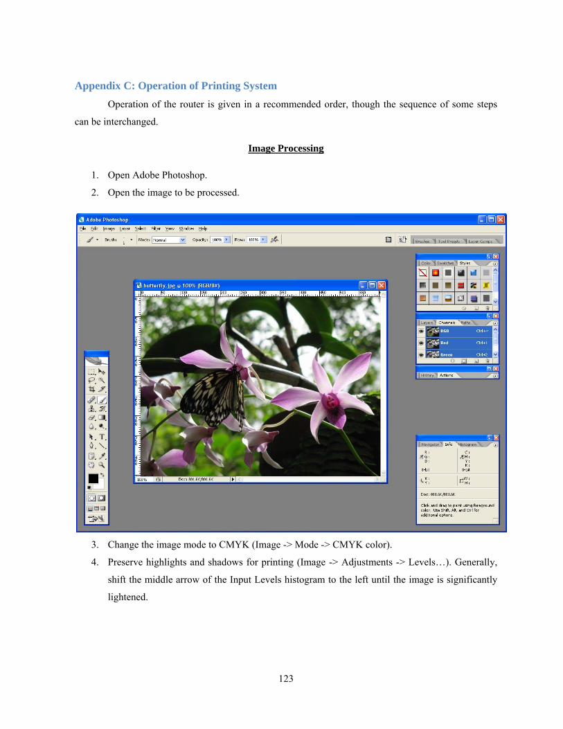
123
Appendix C: Operation of Printing System Operation of the router is given in a recommended order, though the sequence of some steps
can be interchanged.
Image Processing
1. Open Adobe Photoshop.
2. Open the image to be processed.
3. Change the image mode to CMYK (Image -> Mode -> CMYK color).
4. Preserve highlights and shadows for printing (Image -> Adjustments -> Levels…). Generally,
shift the middle arrow of the Input Levels histogram to the left until the image is significantly
lightened.
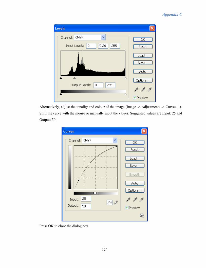
Appendix C
124
Alternatively, adjust the tonality and colour of the image (Image -> Adjustments -> Curves…).
Shift the curve with the mouse or manually input the values. Suggested values are Input: 25 and
Output: 50.
Press OK to close the dialog box.
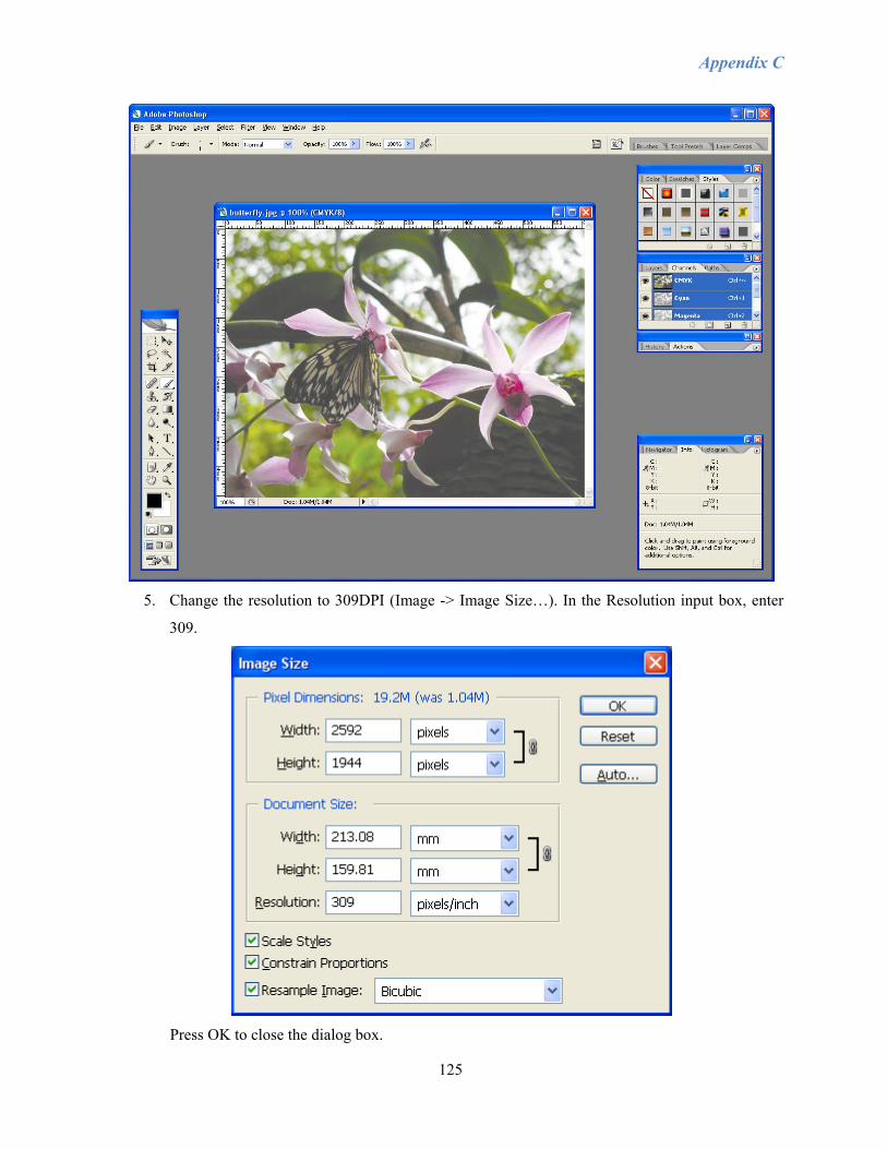
Appendix C
125
5. Change the resolution to 309DPI (Image -> Image Size…). In the Resolution input box, enter
309.
Press OK to close the dialog box.
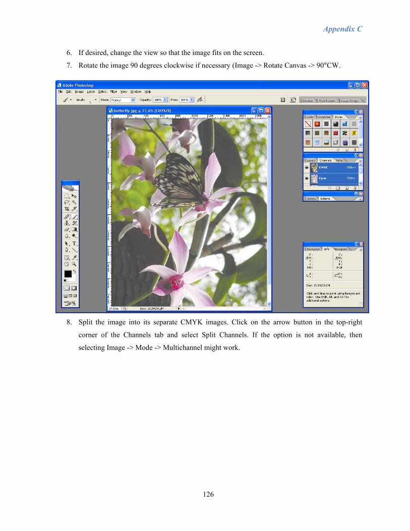
Appendix C
126
6. If desired, change the view so that the image fits on the screen.
7. Rotate the image 90 degrees clockwise if necessary (Image -> Rotate Canvas -> 90°CW.
8. Split the image into its separate CMYK images. Click on the arrow button in the top-right
corner of the Channels tab and select Split Channels. If the option is not available, then
selecting Image -> Mode -> Multichannel might work.
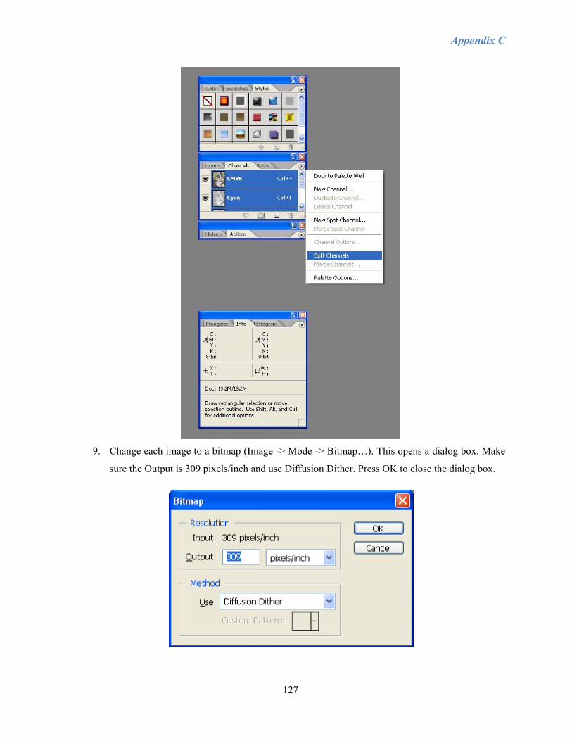
Appendix C
127
9. Change each image to a bitmap (Image -> Mode -> Bitmap…). This opens a dialog box. Make
sure the Output is 309 pixels/inch and use Diffusion Dither. Press OK to close the dialog box.

Appendix C
128
10. Save each image according to the following naming convention, where Name is whatever the
file will be called:
Cyan Name11A.bmp
Magenta Name11B.bmp
Yellow Name12A.bmp
Black Name12B.bmp
Make sure that the file format is set to BMP.
Setting up
1. Plug the power cable for the router into the 400V outlet, pushing as far as possible and twisting
counter-clockwise to ensure complete contact.
2. On the fuse box, flip up the switch labelled “router control” to the ON position.
3. Flip up the corresponding “router control” fuse switch at the back of the router.
4. Press the green button on the lower left side at the front of the router to supply power to turn on
the router.
5. In the same area, check that the ink supply controller is properly connected to power, the ink
pumps, header tanks, and the RS232 cable to the computer. Also check that the two RS232
extension cables are secure.
6. Turn on the ink supply controller by pressing the switch. Green lights will indicate the status of
the device.
7. Remove the hitch pins and cover from the bottom of the printheads and place away from router.
8. Turn the manual valves leading to the printheads so that the ink is free to flow. The valves are
open when they are pointing in the same direction as the tubing. DO NOT open the valves
before turning on the ink supply controller. Without the vacuum to maintain negative pressure
at the nozzle plates, ink will leak from the printheads.
9. Check that the router has been configured for external control.
10. Place the dSPACE close to the encoder cables from the router.
11. Plug the power cable for the dSPACE into a nearby outlet.
12. Plug the network cable into the dSPACE and the computer.
13. Verify that the software license key for the dSPACE is in one of the available USB ports.
14. Open MATLAB 7.0.4 on the computer connected to the router. Only version 7.0.4 is
compatible with the dSPACE controller.
15. Open the printing demo file.

Appendix C
129
16. Open the model.
17. Check that the dSPACE configuration for digital (rotary) and analog (linear) ports corresponds
to the ports needed in the model. If not, then either the leadscrew model must be changed to
match the dSPACE configuration or the chips must be manually changed on the board inside
dSPACE. Be sure to remember the orientation of the metal cover to the dSPACE when taking it
apart, as one side is specially coated. When changing the leadscrew model, check that the
encoder counts have been changed to correspond with the linear (4096) and rotary (4) encoders.
18. Connect the BNC connectors according to the layout defined in the model. Failure to make the
proper connections will result in highly undesirable control. Opposite ends of the BNC
connectors should also be connected to the corresponding ports on the Pulse Width Modulator
(PWM).
19. Ensure all necessary cables are connected to the XUSB: two firewire cables to the head
personality card unit, power supply connector, and USB cable connected to a USB 2.0 port on
the computer with no other devices sharing the same board, otherwise the XUSB software will
not load properly. The USB cable also has two USB repeaters which should be secured. DO
NOT change connections while the XUSB is powered. Hot-plugging will cause damage to the
electronics.
20. Turn on the power supply for the XUSB, located on the lower right side at the front of the
router. Green lights will indicate the status.
21. Clear the router area and surface.
22. Turn on the dSPACE and PWM.
23. On the computer, open the InkSystem software.
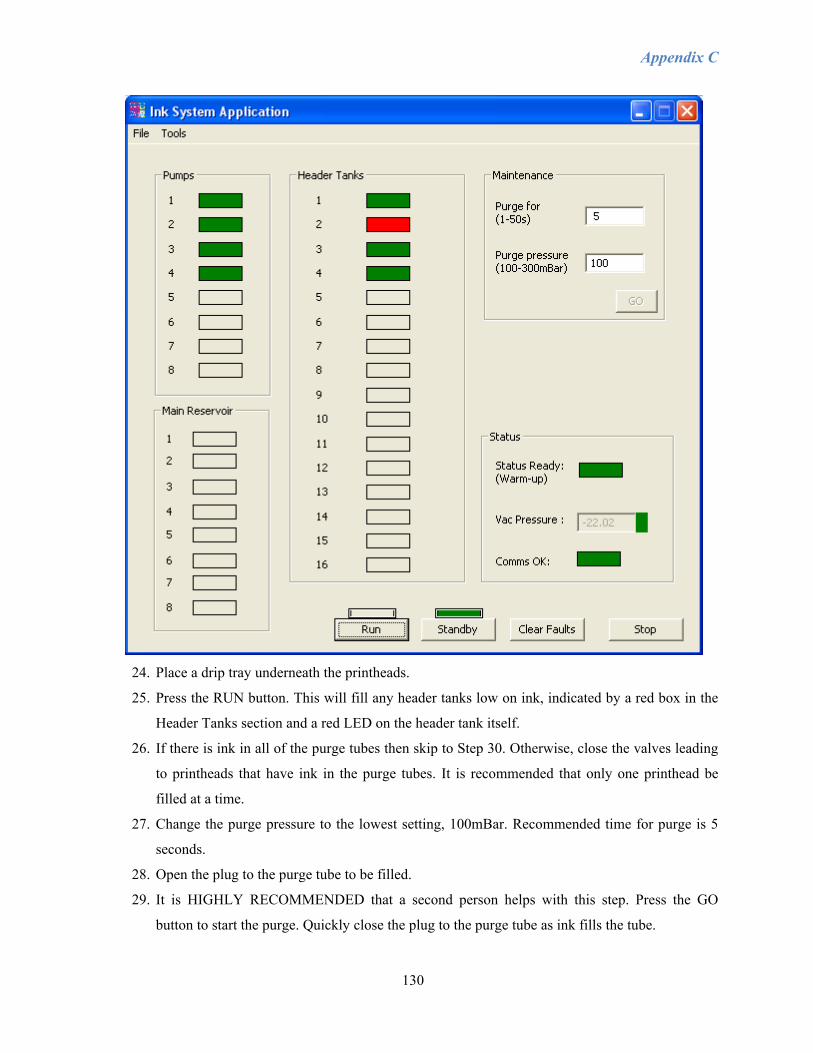
Appendix C
130
24. Place a drip tray underneath the printheads.
25. Press the RUN button. This will fill any header tanks low on ink, indicated by a red box in the
Header Tanks section and a red LED on the header tank itself.
26. If there is ink in all of the purge tubes then skip to Step 30. Otherwise, close the valves leading
to printheads that have ink in the purge tubes. It is recommended that only one printhead be
filled at a time.
27. Change the purge pressure to the lowest setting, 100mBar. Recommended time for purge is 5
seconds.
28. Open the plug to the purge tube to be filled.
29. It is HIGHLY RECOMMENDED that a second person helps with this step. Press the GO
button to start the purge. Quickly close the plug to the purge tube as ink fills the tube.

Appendix C
131
30. Purge the printheads. Set a purge pressure and length of time for the purge. Press GO to start
the purge. Remove the drip tray.
31. Wipe the nozzle plate with lint-free swabs in one direction only (along the length of the plate),
being extremely careful not to scratch the plate. If there is an excessive amount of ink, then
remove some of the ink with lint-free wipes, being careful not to touch the nozzle plate. DO
NOT reuse wipes or swabs. DO NOT mix colours.
32. Open the XUSB software. If a window pops up saying it is unable to load the device driver,
then make sure the power supply is powered, the USB cable is connected properly, and then try
restarting the computer. If that does not work, then the driver for the XUSB software will need
to be reloaded (Scorpion.exe version 4.1 or higher), possibly followed by restarting the
computer.
33. Check the settings (XaarPrint -> Parameters).
34. Activate the printheads to be used in the XUSB/PrintHead Select tab. PrintHead1 is really the
first board of the Head Personality Card unit and PrintHead2 is the second card. Each card goes
to two printheads. So the first checkbox beside PrintHead1 represents Cyan and the checkbox
to the right of that is Magenta. Likewise, the checkbox beside PrintHead2 represents Yellow
and the one to the right of that is Black. Ensure that the Power is checked for both cards.
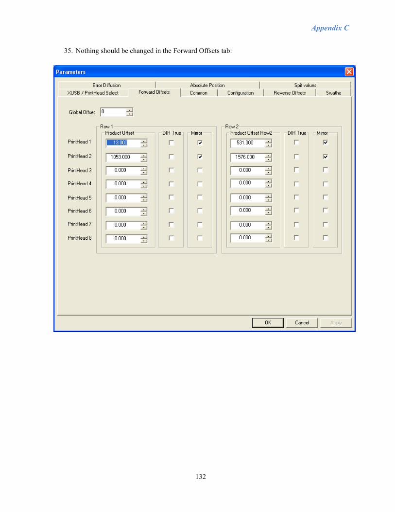
Appendix C
132
35. Nothing should be changed in the Forward Offsets tab:
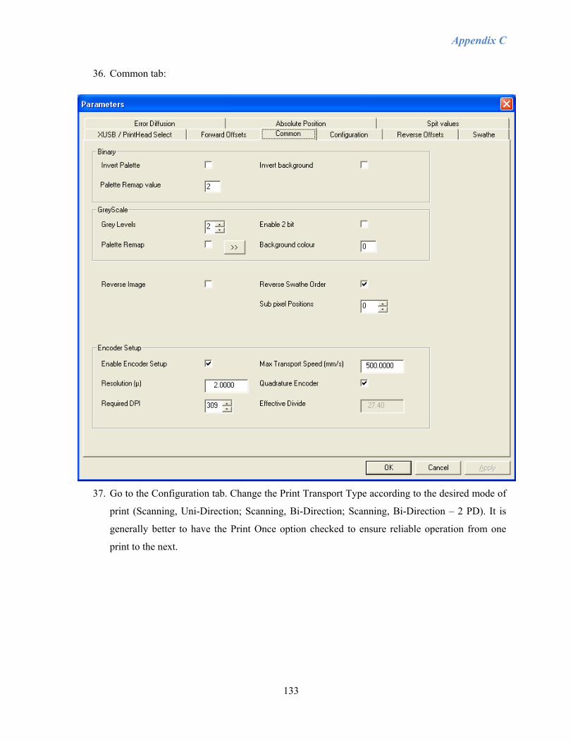
Appendix C
133
36. Common tab:
37. Go to the Configuration tab. Change the Print Transport Type according to the desired mode of
print (Scanning, Uni-Direction; Scanning, Bi-Direction; Scanning, Bi-Direction – 2 PD). It is
generally better to have the Print Once option checked to ensure reliable operation from one
print to the next.
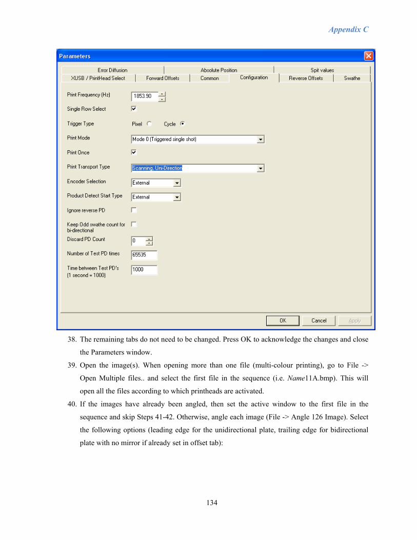
Appendix C
134
38. The remaining tabs do not need to be changed. Press OK to acknowledge the changes and close
the Parameters window.
39. Open the image(s). When opening more than one file (multi-colour printing), go to File ->
Open Multiple files.. and select the first file in the sequence (i.e. Name11A.bmp). This will
open all the files according to which printheads are activated.
40. If the images have already been angled, then set the active window to the first file in the
sequence and skip Steps 41-42. Otherwise, angle each image (File -> Angle 126 Image). Select
the following options (leading edge for the unidirectional plate, trailing edge for bidirectional
plate with no mirror if already set in offset tab):

Appendix C
135
Press OK to accept.
41. Save each image over its original file and close each file.
42. Reopen the image(s) and set the active window to the first image in the sequence (i.e.
Name11A.bmp).
Running the Printing Program
1. Check the image dimensions in Photoshop.
2. Change the image height as the width and the image width as the height in millimetres into the
MATLAB code.
3. Select the method of print: 1 for unidirectional, 2 for bidirectional – 1PD, and 3 for
bidirectional – 2PD. This must match the setting chosen in the XUSB software parameters.
4. Place the substrate into the desired position.
5. Measure the thickness of the substrate.
6. Enter this value into the MATLAB code plus the 1mm clearance between the substrate and
printheads.
7. Run the MATLAB program.
8. When the model finishes loading to dSPACE, open Control Desk.
9. Load the .sdf created from compiling the model to the DS1002 platform by dragging the file
onto the platform symbol.
10. When it finishes loading, open the jogging experiment.
11. Select RUN.
12. Turn on the router (green button at front-right of router) and wait by the emergency stop (red
push-button next to the green button) to verify that all axes are stable. Turning on the router

Appendix C
136
before this step could result in undesirable motion. Non-terminated signals from other
MATLAB code have been known to continue sending signals while the router is turned off.
13. In Control Desk, press the RESET button to reset all the encoders. None of the axes should be
activated.
14. Activate all axes.
15. Press the MANUAL button.
16. Enter a travel distance in millimetres into the input box for Z2 (press ENTER to submit the
value while in the input box cursor or use the arrow buttons to increase or decrease the value).
17. Press the Up or Down buttons accordingly to move the printhead mount within range of home
position. Be careful not to exceed the limitations of movement.
18. Similarly move the X and Y axes into the desired position. Both XL and XR must be activated
at the same time.
19. If Z2 has travelled a large distance (> 5mm), then deactivate the Z2 axis before resetting the
encoders. Otherwise, leave it activated.
20. IMPORTANT: Deactivate XL, XR, and Y axes.
21. Reset the encoders.
22. If Z2 has dropped out of range, then activate Z2 and repeat steps 16 through 22 as necessary.
23. IMPORTANT: switch the program back to Automatic control to allow MATLAB to control the
router motion.
24. Return to the MATLAB window and press a key to start the homing routine.
25. Once it is finished, verify that the displayed graph shows the axis has been homed. If it does
not, then the Control Desk program may have been left in Manual mode and all axes except Z2
MUST be deactivated and the program restarted. If the axis still does not home, then close
Control Desk, restart MATLAB (CTRL+C to end the program), and go back to step 7. The last
solution would be to close all programs, turn off the router, restart the computer and necessary
programs, and go back to step 7.
26. Go to the XUSB software and start the print.
27. Return to the MATLAB prompt and press a key to continue and again to start the printing
routine.
28. Place a hand over the emergency stop while the printing routine is running. Possible reasons for
stopping include erratic motion, printhead mount contacting substrate, and safety.

Appendix C
137
29. When printing has completed and the axes have returned to home position, check the printed
image for any flaws.
30. Go to the XUSB software, acknowledge the print completion, and stop the print.
To continue printing, the steps are fairly similar and can begin with the software steps. If the
trajectory does not need to change, then the model does not need to be built to the dSPACE
environment. The memory allocated to the trajectory should be fairly large; otherwise the .sdf may need
to be reloaded to the DS1002 platform in Control Desk (stop the program and then remove the platform
by pressing the red button). Remember to activate the Z2 control since the printhead mount may have
dropped due to the weight when the control was deactivated after printing. If printing the same image
over again, the “print once” option can be deactivated under the printhead configuration and the start
print will only need to be pressed once. However, when making changes to the settings in Scorpion
version 4.1, such as powering on and off certain printheads or changing offsets, then the changes must
be made while print mode is stopped.
Shutting Down
1. Press the Emergency stop button on the router.
2. Stop the animation in Control Desk. Remove the platform by pressing the red button. Close
Control Desk.
3. Stop the Ink System program. Close Ink System.
4. Stop print mode in the XUSB software if this has not been done already. Close the XUSB
software.
5. Turn off the XUSB.
6. IMPORTANT: Close the manual valves above the printheads. Handles should be pointed in the
direction opposing the motion of ink flow.
7. Place the cover back over the bottom of the printheads using the hitch pins.
8. Turn off the Ink Supply Controller.
9. Turn off the router panel.
10. Turn off the two fuse switches.
11. Unplug the router.
12. Turn off the pulse-width modulator.
13. Turn off the dSPACE.

138
Appendix D: Additional Calibration Measurements and Calculations Cyan and Magenta Alignment
Minimum Distortion Radius [µm]
Maximum Distortion Radius [µm]
Combined Aligned Radius [µm]
Average 63.5843 84.9622 82.5647 Maximum 66.5313 89.0081 85.4118 Minimum 60.2378 81.8155 80.9164
Results from Correct XUSB Image Settings
Note: It was not until the new mounting plate for bidirectional printing was installed that the image
settings were corrected. It is believed that the discrepancies between swaths 1-2 and swaths 3-4 are a
result of the mounting plate being tilted.
Unidirectional Printing:
Vertical Offset Measurements Between Swath 1 and Swath 2 [µm] Between Swath 3 and Swath 4 [µm]
Average 212.1808 243.6483 Maximum 219.3734 253.5381 Minimum 202.291 235.5567
Horizontal Offset Measurements Swaths 1-2 [µm] Swaths 3-4 [µm]
Average 9.541611 37.2616 Maximum 23.503 53.0452 Minimum 1.8079 16.184
Bidirectional Printing:
Bidirectional Horizontal Offsets [µm] 1PD
Swaths 1-2 at 250
mm/sec
1PD Swaths 3-4 at 250
mm/sec
1PD Swaths
1-2 at 50 mm/sec
1PD Swaths
3-4 at 50 mm/sec
2PD Swaths 1-2 at 250
mm/sec
2PD Swaths 3-4 at 250
mm/sec
2PD Swaths
1-2 at 50 mm/sec
2PD Swaths 3-4 at
50 mm/sec
Average 71.626 10.4892 14.5849 53.6449 14.2854 11.5880 8.4913 25.0742 Maximum 92.604 26.073 25.174 80.0173 26.973 32.367 19.7796 44.0544 Minimum 58.4396 0.899 4.4953 21.5777 2.6972 4.4954 1.7981 3.596
Again, the 2PD results show significant improvement and more consistency over the 1PD results.
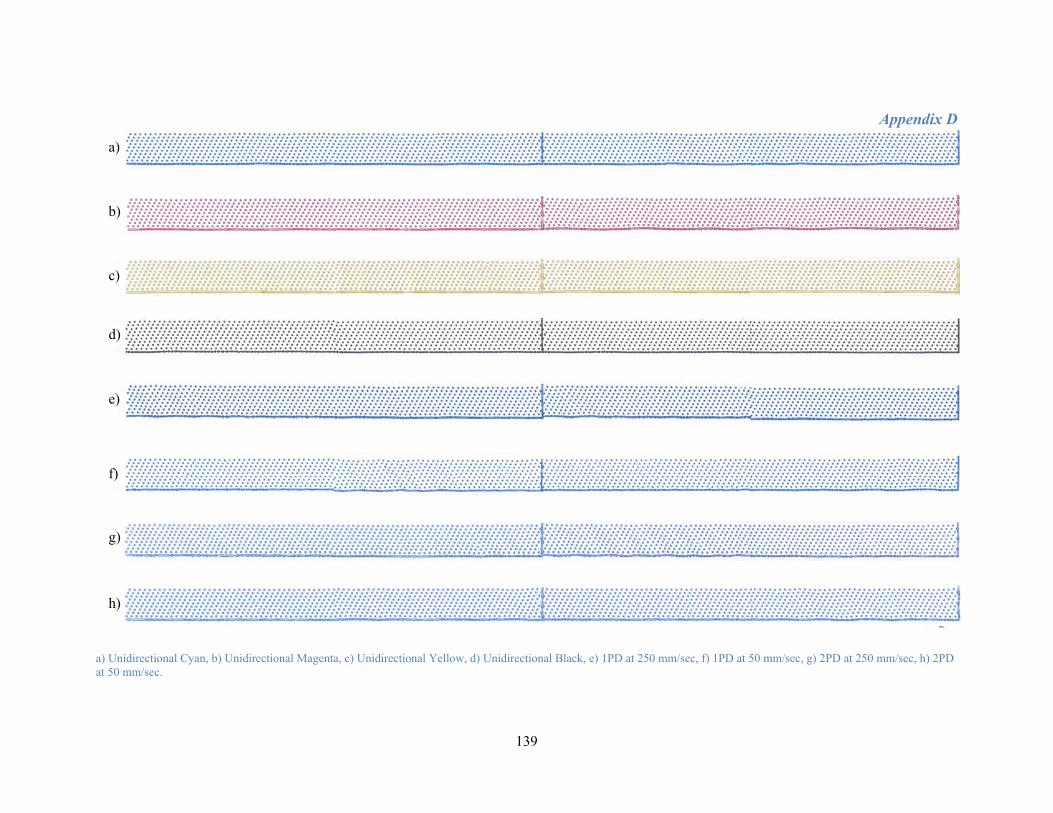
Appendix D
139
a) Unidirectional Cyan, b) Unidirectional Magenta, c) Unidirectional Yellow, d) Unidirectional Black, e) 1PD at 250 mm/sec, f) 1PD at 50 mm/sec, g) 2PD at 250 mm/sec, h) 2PD at 50 mm/sec.
a)
b)
c)
d)
e)
f)
g)
h)

Appendix D
140
Droplet Placement Error Calculations
Parameters Density of Ink [g/cm3] 0.87
Vertical Velocity [m/sec] 6 Volume of Droplet [pL] 50
Horizontal Velocity [mm/sec] 250 Viscosity of Air [g/cm·s] 0.0001827
Diameter of Droplet [cm], D:
004570781.01050432
432 3
93 =⎟
⎟⎠
⎞⎜⎜⎝
⎛ ×=⎟⎟
⎠
⎞⎜⎜⎝
⎛=
−
ππVD
This diameter is within the range such that Brownian motion is not significant.
Relaxation Time Constant, τ [sec]:
005526996.087.00001827.000457.0
181
181 22
=⎟⎟⎠
⎞⎜⎜⎝
⎛⎟⎠⎞
⎜⎝⎛=⎟⎟
⎠
⎞⎜⎜⎝
⎛⎟⎠⎞
⎜⎝⎛= droplet
air
D ρη
τ
Time Taken for Droplet to Travel 1 mm from Nozzle to Substrate, t [sec]:
( ) ( ) ( )( )( ) ( )( ) ( )( )
000169.018.900553.0600553.08.900553.0001.0
100553.0
=−−+=
−−+=−
−
tet
egvgttyt
tviv
ττττ
Horizontal Distance Travelled After t Seconds [mm]:
( ) ( )( ) ( ) ( )( ) 041661.0100553.025.01 00553.0000169.0 =−=−= −− eevty thih
ττ
Deviation Angle, ϴ [degrees]:
38562127.21
041661.0arctan =⎟⎠⎞
⎜⎝⎛=θ
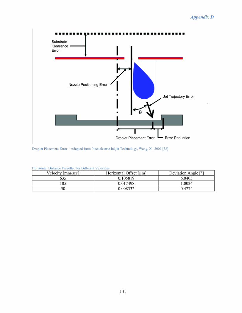
Appendix D
141
Droplet Placement Error – Adapted from Piezoelectric Inkjet Technology, Wang, X., 2009 [38]
Horizontal Distance Travelled for Different Velocities Velocity [mm/sec] Horizontal Offset [µm] Deviation Angle [°]
635 0.105819 6.0405 105 0.017498 1.0024 50 0.008332 0.4774