Development of a Utility Conflict Management System · DEVELOPMENT OF A UTILITY CONFLICT MANAGEMENT...
248
Technical Report Documentation Page 1. Report No. FHWA/TX-09/0-5475-4 2. Government Accession No. 3. Recipient's Catalog No. 4. Title and Subtitle DEVELOPMENT OF A UTILITY CONFLICT MANAGEMENT SYSTEM 5. Report Date October 2008 Published: February 2009 6. Performing Organization Code 7. Author(s) Edgar Kraus, Cesar Quiroga, Nicholas Koncz, and Hussam Dawood 8. Performing Organization Report No. Report 0-5475-4 9. Performing Organization Name and Address Texas Transportation Institute The Texas A&M University System College Station, Texas 77843-3135 10. Work Unit No. (TRAIS) 11. Contract or Grant No. Project 0-5475 12. Sponsoring Agency Name and Address Texas Department of Transportation Research and Technology Implementation Office P. O. Box 5080 Austin, Texas 78763-5080 13. Type of Report and Period Covered Technical Report: September 2005 – August 2008 14. Sponsoring Agency Code 15. Supplementary Notes Project performed in cooperation with the Texas Department of Transportation and the Federal Highway Administration. Project Title: Collection, Integration, and Analysis of Utility Data in the Transportation Project Development Process URL: http://tti.tamu.edu/documents/0-5475-4.pdf 16. Abstract A critical process for the timely development and delivery of highway construction projects is the early identification and depiction of utility interests that may interfere with proposed highway facilities. The effective management of such utility interests or conflicts involves utility relocation (or design changes), inspection, and documentation. The large number of stakeholders and the magnitude of the process results in an enormous amount of data. Despite substantial data exchange between stakeholders, there are currently no standards for the exchange of utility data/information in the project development process. The research will address this issue by analyzing specific information flows and data needs to determine data models and by developing a prototype utility conflict data management system. More specifically, the research will perform a comprehensive analysis of utility conflict data/information flows between utility accommodation stakeholders in the TxDOT project development process, develop data models to accommodate work and data flows between such stakeholders, develop a prototype system for the management of utility conflict data, and develop a tool for the visualization and analysis of utility conflicts within the prototype. The report includes a review of utility relocation and coordination practices, describes the development of data models, and illustrates the development of the prototype conflict management system. 17. Key Words Utility Conflict, Utility Accommodation, Utility Relocation, Utility Reimbursement, Utility Adjustment, Utility Coordination, Utility Management 18. Distribution Statement No restrictions. This document is available to the public through NTIS: National Technical Information Service Springfield, Virginia 22161 http://www.ntis.gov 19. Security Classif.(of this report) Unclassified 20. Security Classif.(of this page) Unclassified 21. No. of Pages 248 22. Price Form DOT F 1700.7 (8-72) Reproduction of completed page authorized
Transcript of Development of a Utility Conflict Management System · DEVELOPMENT OF A UTILITY CONFLICT MANAGEMENT...

Technical Report Documentation Page 1. Report No.
FHWA/TX-09/0-5475-4
2. Government Accession No.
3. Recipient's Catalog No.
4. Title and Subtitle
DEVELOPMENT OF A UTILITY CONFLICT MANAGEMENT
SYSTEM
5. Report Date
October 2008
Published: February 2009 6. Performing Organization Code
7. Author(s)
Edgar Kraus, Cesar Quiroga, Nicholas Koncz, and Hussam Dawood
8. Performing Organization Report No.
Report 0-5475-4 9. Performing Organization Name and Address
Texas Transportation Institute
The Texas A&M University System
College Station, Texas 77843-3135
10. Work Unit No. (TRAIS)
11. Contract or Grant No.
Project 0-5475 12. Sponsoring Agency Name and Address
Texas Department of Transportation
Research and Technology Implementation Office
P. O. Box 5080
Austin, Texas 78763-5080
13. Type of Report and Period Covered
Technical Report:
September 2005 – August 2008 14. Sponsoring Agency Code
15. Supplementary Notes
Project performed in cooperation with the Texas Department of Transportation and the Federal Highway
Administration.
Project Title: Collection, Integration, and Analysis of Utility Data in the Transportation Project Development
Process
URL: http://tti.tamu.edu/documents/0-5475-4.pdf 16. Abstract
A critical process for the timely development and delivery of highway construction projects is the early
identification and depiction of utility interests that may interfere with proposed highway facilities. The
effective management of such utility interests or conflicts involves utility relocation (or design changes),
inspection, and documentation. The large number of stakeholders and the magnitude of the process results in
an enormous amount of data. Despite substantial data exchange between stakeholders, there are currently no
standards for the exchange of utility data/information in the project development process. The research will
address this issue by analyzing specific information flows and data needs to determine data models and by
developing a prototype utility conflict data management system. More specifically, the research will perform
a comprehensive analysis of utility conflict data/information flows between utility accommodation
stakeholders in the TxDOT project development process, develop data models to accommodate work and
data flows between such stakeholders, develop a prototype system for the management of utility conflict
data, and develop a tool for the visualization and analysis of utility conflicts within the prototype. The report
includes a review of utility relocation and coordination practices, describes the development of data models,
and illustrates the development of the prototype conflict management system.
17. Key Words
Utility Conflict, Utility Accommodation, Utility
Relocation, Utility Reimbursement, Utility
Adjustment, Utility Coordination, Utility
Management
18. Distribution Statement
No restrictions. This document is available to the
public through NTIS:
National Technical Information Service
Springfield, Virginia 22161
http://www.ntis.gov 19. Security Classif.(of this report)
Unclassified
20. Security Classif.(of this page)
Unclassified
21. No. of Pages
248
22. Price
Form DOT F 1700.7 (8-72) Reproduction of completed page authorized

DEVELOPMENT OF A UTILITY
CONFLICT MANAGEMENT SYSTEM
by
Edgar Kraus, P.E.
Assistant Research Engineer
Texas Transportation Institute
Cesar Quiroga, P.E.
Research Engineer
Texas Transportation Institute
Nicholas Koncz
Assistant Research Scientist
Texas Transportation Institute
and
Hussam Dawood
Student Programmer
Texas Transportation Institute
Report 0-5475-4
Project 0-5475
Project Title: Collection, Integration, and Analysis of Utility Data in the Transportation Project
Development Process
Performed in cooperation with the
Texas Department of Transportation
and the
Federal Highway Administration
October 2008
Published: February 2009
TEXAS TRANSPORTATION INSTITUTE
The Texas A&M University System
College Station, Texas 77843-3135


v
DISCLAIMER
The contents of this document reflect the views of the authors, who are responsible for the facts
and the accuracy of the data presented herein. The contents do not necessarily reflect the official
view or policies of the Federal Highway Administration (FHWA) or the Texas Department of
Transportation (TxDOT). This document does not constitute a standard, specification, or
regulation, nor is it intended for construction, bidding, or permit purposes. The engineer in
charge of the project was Edgar Kraus, P.E. (Texas Registration #96727).
The United States Government and the State of Texas do not endorse products or manufacturers.
Trade or manufacturers’ names appear herein solely because they are considered essential to the
object of this report.

vi
ACKNOWLEDGMENTS
This research was conducted in cooperation with TxDOT and FHWA. The researchers would
like to gratefully acknowledge the assistance provided by TxDOT officials, in particular the
following:
Randall ―Randy‖ Anderson (project director);
John Campbell, Right of Way Division (program coordinator);
Jesse Cooper, Right of Way Division;
Terri Evans, Right of Way Division;
Jim Kuhn, Technology Services Division;
Sylvia Medina, Research and Technology Implementation Office;
Gary Ray, Houston District;
Mak Saeedi, Right of Way Division;
Duncan Stewart, Research and Technology Implementation Office;
Karen Van Hooser, Technology Services Division; and
Tom Yarbrough, Research and Technology Implementation Office.
The researchers would like to acknowledge the assistance provided by several TxDOT staff
members: Amarillo District: Larry Black (retired). Austin District: Shelly Easley. Bryan
District: Darrel Kolwes and Bob Richardson. Corpus Christi District: Jose Gaytan, Ron Stuckey,
and Victor Vourcos. Dallas District: Murray Allen and Travis Henderson. Houston District:
William Brudnick, Allen Byerly, Stephen Gbur, Richard Lumpkin, Oscar Medrano, David
Roberts, Stephen Stakemiller, and Ivor Walker. San Antonio District: Richard Butler, Lizette
Colbert, Gregg Granato, Rick Hanks, Mike Lehmann, and Kathryn Pearson. Tyler District:
David Wicks. Yoakum District: Bob Clark and Bobby Harraid.
The researchers are grateful for the significant programming effort provided by Jerry Le at the
Texas Transportation Institute, and the assistance provided by Ryan Brown, Christopher
Kawasaki, Jayashri Patil, and Pho Trung.

vii
TABLE OF CONTENTS
Page
LIST OF FIGURES ................................................................................................................. xii
LIST OF TABLES ...................................................................................................................xiv
LIST OF ACRONYMS, ABBREVIATIONS, AND TERMS ...................................................xvi
CHAPTER 1. INTRODUCTION ...............................................................................................1
RESEARCH OBJECTIVES ....................................................................................................2
CHAPTER 2. UTILITY DATA MANAGEMENT PRACTICES AT TXDOT ...........................3
INTRODUCTION ..................................................................................................................3
METHODOLOGY ..................................................................................................................3
REVIEW OF EXISTING TECHNICAL DOCUMENTATION...............................................4
TxDOT PDP Manual ...........................................................................................................5
TxDOT PS&E Preparation Manual and Utility Manual .......................................................5
Challenges with Existing Technical Documentation ............................................................9
DATA MANAGEMENT-RELATED PRACTICES AND PLANS ....................................... 11
Document Archival Processes ........................................................................................... 11
INFORMATION SYSTEMS RELATED TO UTILITY ACTIVITIES IN THE PDP ............ 12
Bentley ProjectWise .......................................................................................................... 12
Design and Construction Information System .................................................................... 13
FileNet .............................................................................................................................. 16
Highway Project Task Management System ...................................................................... 19
San Antonio Construction Project Database ....................................................................... 20
Plans Online ...................................................................................................................... 22
Right of Way Information System (ROWIS) ..................................................................... 23
Right of Way Division Utility Agreement Database ........................................................... 26
San Antonio District File Management System .................................................................. 28
Texas Reference Marker System........................................................................................ 28
GEOGRAPHIC INFORMATION SYSTEM PRACTICES AND PLANS ............................. 31
TxDOT GIS Architecture and Infrastructure Project .......................................................... 32
GIS-Based Information Systems ........................................................................................ 38
Main Street Texas .......................................................................................................... 38
Right of Way Map Locator ............................................................................................ 39
Survey Primary Control Markers ................................................................................... 40
Utility Facility Database ................................................................................................ 41
Utility Installation Review System ................................................................................. 42
CHAPTER 3. UTILITY COORDINATION ACTIVITIES OF PDP STAKEHOLDERS ......... 43
INTRODUCTION ................................................................................................................ 43

viii
UTILITY COORDINATION AT TXDOT DISTRICTS ....................................................... 43
Utility Coordination at the Austin District ......................................................................... 43
Utility Coordination Process .......................................................................................... 43
Utility Coordination Issues ............................................................................................ 44
Current Utility Tracking and Conflict Management ....................................................... 45
Recommendations for a Future Utility Information Management System....................... 47
Utility Coordination at the Dallas District Office ............................................................... 48
Utility Coordination Process .......................................................................................... 48
Utility Coordination Issues ............................................................................................ 51
Current Utility Tracking and Conflict Management ....................................................... 52
Recommendations for a Future Utility Information Management System....................... 52
Utility Coordination at the Houston District Office ............................................................ 53
Utility Coordination Process .......................................................................................... 53
Utility Coordination Issues ............................................................................................ 55
Current Utility Tracking and Conflict Management ....................................................... 56
Recommendations for a Future Utility Information Management System....................... 56
Utility Coordination at the San Antonio District Office...................................................... 57
Utility Coordination Process .......................................................................................... 57
Utility Coordination Issues ............................................................................................ 59
Current Utility Tracking and Conflict Management ....................................................... 60
Recommendations for a Future Utility Information Management System....................... 61
UTILITY OWNERS AND CONSULTANTS ....................................................................... 61
Utility Survey .................................................................................................................... 62
Utility Companies Contacted ......................................................................................... 62
Utility Consultants Contacted ........................................................................................ 62
Utility Coordination Business Process Model .................................................................... 62
Utility Notification ........................................................................................................ 63
Use of Consultants ......................................................................................................... 63
Utility Coordination Meeting ......................................................................................... 63
Utility Conflict Resolution ............................................................................................. 64
Observations and Trends ................................................................................................... 64
Utility Conflict Notification to Utility Companies.......................................................... 64
Utility Consultants ......................................................................................................... 64
Aerial Utilities ............................................................................................................... 65
Early Involvement in the UCMP .................................................................................... 65
Coordination of New Utility Location ............................................................................ 65
Utility Facility Tracking ................................................................................................ 66
Utility Coordination Issues ................................................................................................ 66
Recommendations for a Utility Data Exchange System ..................................................... 66
CHAPTER 4. DEVELOPMENT OF TXDOT UTILITY RELOCATION BUSINESS PROCESS MODEL .................................................................................................................. 69
INTRODUCTION ................................................................................................................ 69
BUSINESS PROCESS MODEL DEVELOPMENT .............................................................. 70
Sources of Information ...................................................................................................... 70
ix
Integrated Computer-Aided Manufacturing Definition Language Notation ........................ 70
Business Process Modeling Notation ................................................................................. 74
Business Process Model Development Using BPMN ......................................................... 75
UACT BUSINESS PROCESS MODEL DESCRIPTIONS .................................................... 76
Local District Business Process Models ............................................................................. 76
Detailed Business Process Model ...................................................................................... 76
Overview Diagram ............................................................................................................ 84
Data Flow Diagram ........................................................................................................... 84
Business Process Model for Utility Relocation with Prepayment Funding Agreements ...... 87
CHAPTER 5. DEVELOPMENT OF DATA MODELS FOR A PROTOTYPE UTILITY
CONFLICT MANAGEMENT SYSTEM .................................................................................. 89
INTRODUCTION ................................................................................................................ 89
USER, FUNCTIONAL, AND OTHER SYSTEM REQUIREMENTS .................................. 89
UACT User Requirements ................................................................................................. 89
UACT Functional Requirements ........................................................................................ 90
System Interface ............................................................................................................ 90
Document Exchange and Storage................................................................................... 90
Communications ............................................................................................................ 91
Reporting....................................................................................................................... 91
Visualization ................................................................................................................. 91
Compatibility with Existing and Future TxDOT Information Systems ........................... 91
UACT Other System Requirements ................................................................................... 92
Software ........................................................................................................................ 92
Hardware ....................................................................................................................... 92
Interface ........................................................................................................................ 92
Additional Considerations and Recommendations ............................................................. 93
LOGICAL DATA MODEL DEVELOPMENT ..................................................................... 94
Core UACT Data Elements ............................................................................................... 96
ArcSDE Subject Area ........................................................................................................ 99
DCIS Subject Area .......................................................................................................... 102
Document Subject Area ................................................................................................... 103
Feature Subject Area ....................................................................................................... 106
FileNet Subject Area ....................................................................................................... 109
MainStreet Texas Subject Area ........................................................................................ 111
Meeting Subject Area ...................................................................................................... 112
Permissions Subject Area ................................................................................................ 114
Project Subject Area ........................................................................................................ 121
ROWIS Subject Area....................................................................................................... 125
System Subject Area ........................................................................................................ 126
Utility Agreement Assembly Subject Area ...................................................................... 127
Utility Facility Database Subject Area ............................................................................. 133
Utility Installation Review Subject Area .......................................................................... 136
User Subject Area ............................................................................................................ 140
Utility Conflict Subject Area ........................................................................................... 141

x
PHYSICAL DATA MODEL DEVELOPMENT ................................................................. 145
DATA DICTIONARY ........................................................................................................ 146
CHAPTER 6. UTILITY ACCOMMODATION AND CONFLICT TRACKER
PROTOTYPE ......................................................................................................................... 147
INTRODUCTION .............................................................................................................. 147
UACT SYSTEM ARCHITECTURE ................................................................................... 147
Permissions System ......................................................................................................... 151
Utility Conflict List ......................................................................................................... 151
PROTOTYPE FUNCTIONALITY ..................................................................................... 151
Project Business Area ...................................................................................................... 152
Utility Inventory Business Area ....................................................................................... 154
Conflict Tracking Business Area ..................................................................................... 155
Agreement Business Area ................................................................................................ 156
Reports Business Area ..................................................................................................... 157
Contacts Business Area ................................................................................................... 158
Other Resources Business Area ....................................................................................... 159
Administration Section .................................................................................................... 160
Users Business Area ........................................................................................................ 160
Access Control Business Area ......................................................................................... 161
TESTING AND USER FEEDBACK .................................................................................. 161
Feedback from Stakeholders on UACT Prototype ............................................................ 162
Project Business Area .................................................................................................. 162
Utility Inventory Business Area ................................................................................... 163
Conflict Tracking Business Area ................................................................................. 163
Agreement Business Area ............................................................................................ 164
CHAPTER 7. CONCLUSIONS AND RECOMMENDATIONS ............................................ 167
CONCLUSIONS ................................................................................................................. 167
ANTICIPATED BENEFITS OF UACT .............................................................................. 168
RECOMMENDATIONS .................................................................................................... 171
Recommendations Related to the Implementation of UACT ............................................ 171
General Recommendations to Improve/Optimize Utility Coordination Practices
at TxDOT ........................................................................................................................ 176
REFERENCES ....................................................................................................................... 179
APPENDIX A. UTILITY SURVEY ...................................................................................... 185
UTILITY INTERVIEW ...................................................................................................... 187
General Questions ........................................................................................................... 187
Utilities and Utility Conflicts ........................................................................................... 187
APPENDIX B. LIST OF ACTIVITIES IN THE DETAILED BUSINESS PROCESS
MODEL .................................................................................................................................. 189

xi
LIST OF ACTIVITIES BY ACTIVITY GROUP ................................................................ 191
1.1 Project Programming and Funding ............................................................................. 191
1.2 Obtain PLAN Authorization ...................................................................................... 191
1.3 Assign ROW-CSJ ...................................................................................................... 192
1.4 Obtain DEVELOP Authorization ............................................................................... 192
1.5 Obtain CONSTRUCT Authorization ......................................................................... 192
2.1 Data Collection and Preliminary Utility Coordination ................................................ 192
2.2 Preliminary Design (Schematic Design) ..................................................................... 194
2.3 Environmental Documentation................................................................................... 195
2.4 Environmental Clearance ........................................................................................... 195
3.1 PS&E Development (Detailed Design) ...................................................................... 195
3.2 PS&E Assembly/Design Review ............................................................................... 196
4.1 Preliminary Utility Coordination ................................................................................ 196
4.2 Preliminary Right Of Way Research .......................................................................... 197
4.3 SUE Level C and D (Visual and Records) .................................................................. 197
4.4 Right Of Way Mapping Before Letting ...................................................................... 197
4.5 Obtain Right Of Way Release .................................................................................... 198
4.6 SUE Level C (and Some B) ....................................................................................... 198
4.7 Secure Federal, State and Local Funding Agreements ................................................ 199
4.8 Locate Utilities (SUE Level B and Some A) .............................................................. 199
4.9 Right Of Way Acquisition Before Letting .................................................................. 200
4.10 Utility’s Consultant Contract Approval .................................................................... 200
4.11 Agreements with Utilities ........................................................................................ 200
4.12 Locate Utilities (SUE Level A) ................................................................................ 202
4.13 Adjustment Monitoring and Reimbursement Before Letting .................................... 202
4.14 Utility and Right Of Way Certifications ................................................................... 202
4.15 Right Of Way Mapping After Letting ...................................................................... 203
4.16 Right Of Way Acquisition After Letting .................................................................. 203
4.17 Adjustment Monitoring and Reimbursement After Letting ....................................... 203
5.1 Final Processing and Letting ...................................................................................... 204
6.1 Initial Utility Involvement ......................................................................................... 204
6.2 Preliminary Design Meeting ...................................................................................... 204
6.3 Initial Coordination and Markup ................................................................................ 204
6.4 Conflict Determination .............................................................................................. 205
6.5 Utility Design ............................................................................................................ 205
6.6 Utility Adjustment Before Letting .............................................................................. 206
6.7 Utility Adjustment After Letting ................................................................................ 207
APPENDIX C. LOGICAL DATA MODELS OF UTILITY DATA MANAGEMENT SYSTEM PROTOTYPE ......................................................................................................... 209

xii
LIST OF FIGURES
Page
Figure 1. PDP Manual Diagram (Adapted from 14). ...................................................................7
Figure 2. ProjectWise Sample Screenshots (18). ....................................................................... 13
Figure 3. DCIS Project Identification Screen (19). .................................................................... 14
Figure 4. FileNet Sample Screenshots (23). .............................................................................. 17
Figure 5. Corpus Christi District Highway Project Task Management System Screenshots. ...... 20
Figure 6. San Antonio District DCO Database Screenshot (25)................................................. 21
Figure 7. San Antonio District DCO Database ―Project Data Entry‖ Screenshot (25)................ 21
Figure 8. Plans Online Interface (26). ....................................................................................... 23
Figure 9. ROWIS Screenshot. .................................................................................................. 24
Figure 10. ROWIS High-Level Logical Data Model. ................................................................ 25
Figure 11. ROW Division Utility Agreement Database Data Model. ........................................ 27
Figure 12. Reference Markers on the State Highway Network at the Intersection of
Interstates 10 and 610 in Houston. ....................................................................................... 29
Figure 13. Reference Marker 492 on FM 1516. ........................................................................ 30
Figure 14. Traditional and GAIP Approaches to Linear Referencing (33). ................................ 33
Figure 15. Data Modeling in GAIP. .......................................................................................... 35
Figure 16. Main Street Texas Sample Screenshots (43). ........................................................... 39
Figure 17. Right of Way Map Locator Interface (44). ............................................................... 40
Figure 18. Survey Primary Control Markers Interface (45). ...................................................... 41
Figure 19. Use of Construction and Right of Way CSJ Numbers. ............................................. 60
Figure 20. Function Box and Data/Objects Arrows. .................................................................. 71
Figure 21. TxDOT PDP Top-Level Context Diagram. .............................................................. 72
Figure 22. TxDOT PDP Decomposition Child Diagram. .......................................................... 73
Figure 23. Example of Collaboration Business Process Model Using BPMN. .......................... 74
Figure 24. Overview Business Process Model of Utility Relocation in the TxDOT Project
Development Process. ......................................................................................................... 85
Figure 25. System Prototype Data Flow Diagram. .................................................................... 86
Figure 26. UACT Data Model – Core Data Elements. .............................................................. 97
Figure 27. UACT Data Model – High-Level Logical Data Model............................................. 99
Figure 28. UACT Data Model – ArcSDE Subject Area. ......................................................... 100
Figure 29. UACT Data Model – DCIS Subject Area............................................................... 102
Figure 30. UACT Data Model – Document Subject Area. ...................................................... 103
Figure 31. UACT Data Model – Feature Subject Area. ........................................................... 106
Figure 32. UACT Data Model – FileNet Subject Area. ........................................................... 110
Figure 33. UACT Data Model – MainStreet Texas Subject Area. ........................................... 111
xiii
Figure 34. UACT Data Model – Meeting Subject Area. ......................................................... 113
Figure 35. UACT Data Model – Permissions Subject Area. .................................................... 114
Figure 36. Relationship of Roles and Permissions in UACT. .................................................. 117
Figure 37. Relationship of Roles and Privileges in UACT. ..................................................... 117
Figure 38. UACT Data Model – Project Subject Area. ........................................................... 122
Figure 39. UACT Data Model – ROWIS Subject Area. .......................................................... 125
Figure 40. UACT Data Model – System Subject Area. ........................................................... 127
Figure 41. UACT Data Model – Utility Agreement Assembly Subject Area. .......................... 128
Figure 42. UACT Data Model – Utility Facility Database Subject Area. ................................ 133
Figure 43. UACT Data Model – Utility Installation Review Subject Area. ............................. 136
Figure 44. UACT Data Model – User Subject Area. ............................................................... 140
Figure 45. UACT Data Model – Utility Conflict Subject Area. ............................................... 141
Figure 46. UACT System Architecture Diagram. ................................................................... 148
Figure 47. UACT System Architecture. .................................................................................. 149
Figure 48. Project Listing. ...................................................................................................... 153
Figure 49. Utility Inventory Screen. ....................................................................................... 154
Figure 50. Conflict Tracking Screen. ...................................................................................... 155
Figure 51. Agreement Business Area. ..................................................................................... 157
Figure 52. Utility Certification Report. ................................................................................... 158
Figure 53. Contacts Screen. .................................................................................................... 159
Figure 54. Other Resources Business Area. ............................................................................ 160
Figure 55. UACT Logical Data Model, ArcSDE Subject Area................................................ 211
Figure 56. UACT Logical Data Model, DCIS Subject Area. ................................................... 212
Figure 57. UACT Logical Data Model, Document Subject Area. ........................................... 213
Figure 58. UACT Logical Data Model, Feature Subject Area. ................................................ 214
Figure 59. UACT Logical Data Model, FileNet Subject Area. ................................................ 215
Figure 60. UACT Logical Data Model, MainStreet Texas Subject Area. ................................ 216
Figure 61. UACT Logical Data Model, Meeting Subject Area. ............................................... 217
Figure 62. UACT Logical Data Model, Permissions Subject Area. ......................................... 218
Figure 63. UACT Logical Data Model, Project Subject Area. ................................................. 219
Figure 64. UACT Logical Data Model, ROWIS Subject Area. ............................................... 220
Figure 65. UACT Logical Data Model, System Subject Area. ................................................ 221
Figure 66. UACT Logical Data Model, User Subject Area. .................................................... 222
Figure 67. UACT Logical Data Model, UIR Subject Area. ..................................................... 223
Figure 68. UACT Logical Data Model, Utility Agreement Assembly Subject Area. ............... 224
Figure 69. UACT Logical Data Model, Utility Conflict Subject Area. .................................... 225
Figure 70. UACT Logical Data Model, Utility Facility Database Subject Area. ...................... 226

xiv
LIST OF TABLES
Page
Table 1. Comparison of Description and Recommended Attendees for Activity ―Design
Conference.‖ .........................................................................................................................9
Table 2. Sample DCIS File Fields. ........................................................................................... 15
Table 3. Document Classes in the TxDOT FileNet Implementation (Adapted from 22). ........... 18
Table 4. Sample of Record Types and Document Types of the ―Right of Way‖ Document Class (Adapted from 22). ..................................................................................................... 19
Table 5. Plans Online Project and Document Attributes (26). ................................................... 22
Table 6. List of Database Tables in ROWIS. ............................................................................ 25
Table 7. FMS Primary File Types (28). .................................................................................... 28
Table 8. Production GIS Datasets at TxDOT (30). .................................................................... 31
Table 9. Ground Set and Linear Referencing System Entities, Attributes, and Subtypes
(Adapted from 31, 37). ........................................................................................................ 37
Table 10. Detailed Business Process Model Elements and TxDOT Manual Equivalents. .......... 78
Table 11. Detailed Business Process Model Code Overview and Example. .............................. 78
Table 12. Detailed Business Process Model Activity Group Codes and Names by
Swimlane. ........................................................................................................................... 80
Table 13. Detailed Business Process Model Milestones. ........................................................... 82
Table 14. Standard UACT Logical Data Model Datatypes. ....................................................... 94
Table 15. ArcSDE Subject Area Entities. ............................................................................... 101
Table 16. DCIS Subject Area Entities. .................................................................................... 103
Table 17. Document Subject Area Entities. ............................................................................ 105
Table 18. Feature Subject Area Entities. ................................................................................. 108
Table 19. FileNet Subject Area Entities. ................................................................................. 111
Table 20. MainStreet Texas Subject Area Entities. ................................................................. 112
Table 21. Meeting Subject Area Entities. ................................................................................ 114
Table 22. UACT Business Areas and Business Area Sections. ............................................... 116
Table 23. UACT Access Matrix. ............................................................................................ 119
Table 24. Permissions Subject Area Entities. .......................................................................... 121
Table 25. Project Subject Area Entities................................................................................... 124
Table 26. ROWIS Subject Area Entities. ................................................................................ 126
Table 27. System Subject Area Entities. ................................................................................. 127
Table 28. UACT Utility Agreement Event Types. .................................................................. 129
Table 29. Utility Agreement Assembly Subject Area Entities. ................................................ 130
Table 30. UACT Life Cycle Status Options. ........................................................................... 134
Table 31. Utility Facility Database Subject Area Entities. ....................................................... 135
Table 32. Utility Installation Review Subject Area Entities. ................................................... 138

xv
Table 33. User Subject Area Entities. ..................................................................................... 141
Table 34. UACT Utility Conflict Types. ................................................................................. 142
Table 35. UACT Utility Conflict Legal Status Types. ............................................................. 142
Table 36. UACT Utility Conflict Feature Status Types. .......................................................... 143
Table 37. UACT Utility Conflict Resolution Strategy Types. ................................................. 143
Table 38. Utility Conflict Subject Area Entities. ..................................................................... 143

xvi
LIST OF ACRONYMS, ABBREVIATIONS, AND TERMS
AADT Annual Average Daily Traffic
AASHTO American Association of State Highway and Transportation Officials
ADO ActiveX Data Object
AFA Advance Funding Agreement
APA Alternate Procedure Approval
ArcGIS ESRI’s Arc Geographic Information System Software
ArcIMS ESRI’s Arc Internet Map Server
ArcSDE ESRI’s Arc Spatial Data Engine
BAMS/DSS Bid Analysis Management System/Decision Support System
BPM Business Process Model
BPS Bid Proposal System
BPMN Business Process Modeling Notation
CAD Computer Aided Design
CD-ROM Compact Disk Read Only Memory
CDA Comprehensive Development Agreement
CFR Code of Federal Regulations
CMCS Construction and Maintenance Contract System
CS Control Section
CSJ Control Section Job
CCSJ Controlling CSJ Number
CSS2 Cascading Style Sheet Level 2 Specification
CTS Contract Tracking System

xvii
DBB Design-Bid-Build
DBMS Database Management System
DCIS Design and Construction Information System
DCO Design Construction Office
DFD Data Flow Diagram
DFO Distance From Origin
DOE Date of Eligibility
DOT Department of Transportation
DPS Department of Public Safety
DSR Design Summary Report
DTM Digital Terrain Model
EDMS Electronic Document Management System
EDTIS Electronic Document Technologies Implementation and Support
ERwin Computer Associates® AllFusion ERwin
® Data Modeler (now available as
CA® ERwin
® Data Modeler)
ESRI Environmental Systems Research Institute
EWA Emergency Work Authorization
FAQ Frequently Asked Questions
FCA Facility Concession Agreement
FDOT Florida Department of Transportation
FileNet FileNet® Electronic Document Management System
FIPS Federal Information Processing Standards
FHWA Federal Highway Administration

xviii
FMS File Management System
FPAA Federal Project Authorization and Agreement
FUP Federal Utility Procedure of the UCMP
GAIP GIS Architecture and Infrastructure Project
GB Gigabyte
GENII Genesis™
Enterprise Information Integrator
GHz Gigahertz
GIS Geographic Information System
GPS Global Positioning System
GS TxDOT Network Ground Set
HPMS Highway Performance Management System
HPTMS Highway Project Task Management System
HTML HyperText Markup Language
HTTP HyperText Transfer Protocol
ICAM Integrated Computer-Aided Manufacturing
ID Identifier
IDEF ICAM Definition Language
IDEF0 Integration Definition for Function Modeling
IDEF3 Integration Definition for Process Description Capture Method
IHEEP International Highway Engineering Exchange Program
IICE Integration for Concurrent Engineering
IIS Internet Information Server
Interstate System National System of Interstate and Defense Highways
xix
LOA Letter Of Authorization
LOS Level Of Service
LPA Local Public Agency
LRS Linear Referencing System
LUP Local Utility Procedure
MST Main Street Texas
NOPI Notice of Proposed Installation
OCR Optical Character Recognition
OLAP Online Analytical Processing
OLTP Online Transaction Processing
OMG Object Management Group
PDF Portable Document Format
PDP Project Development Process
PMIS Pavement Management Information System
PS&E Plans, Specifications, and Estimates
RAM Random Access Memory
RDBMS Relational Database Management System
RHiNo Roadway/Highway Network Inventory
ROW TxDOT Right of Way Division
ROWIS Right of Way Information System
SAS Statistical Analysis Software
SATA Serial Advanced Technology Attachment
SB Senate Bill
xx
SMS Subcontractor Monitoring System
SP Service Pack
SQL Structured Query Language
StratMap Texas Strategic Mapping Program
SUE Subsurface Utility Engineering
SUP State Utility Procedure of the UCMP
TACS Tables and Characteristics System
TB Terabyte
TGIC Texas Geographic Information Council
TIF Tagged Image File
TIP Transportation Improvement Plan
TNRIS Texas Natural Resources Information System
TPP Transportation Planning and Programming Division
TRM Texas Reference Marker
TRMEOY Texas Reference Marker End of Year
TSD Technology Services Division at TxDOT
TSID TxDOT System Interface Diagram
TSPS Texas Society of Professional Surveyors
TTA Texas Turnpike Authority
TxDOT Texas Department of Transportation
TPP Transportation Planning and Programming Division at TxDOT
UAA Utility Agreement Assembly
UACT Utility Accommodation and Conflict Tracker

xxi
UAD Utility Agreement Database (used by TxDOT ROW)
UAR Utility Accommodation Rules (formerly Utility Accommodation Policy)
UFD Utility Facility Database
UIR Utility Installation Review
UCMP Utility Cooperative Management Process
UJUA Utility Joint Use Acknowledgement
UTP Unified Transportation Program
W3C World Wide Web Consortium
XHTML Extensible HyperText Markup Language
XML Extensible Markup Language


Report 0-5475-4
1
CHAPTER 1. INTRODUCTION
Early identification and depiction of utility interests that may interfere with proposed highway
facilities is a critical process for the timely development and delivery of highway construction
projects (1). Utility conflicts occur as a result of a proposed highway design when a utility
facility is in conflict with the proposed highway facility, other utility installations, or non-
compliance with the Utility Accommodation Rules (UAR) (2). It is then necessary to address or
clear such conflicts by using strategies such as (a) introducing a design change to the horizontal
or vertical alignment of the proposed highway facility; (b) removing, relocating, or otherwise
adjusting the utilities in conflict; (c) implementing an appropriate engineering countermeasure
other than a roadway design change or utility adjustment; and (d) accepting an exception to
policy. During the process of detecting, confirming, and resolving conflicts, a suspected conflict
may also be removed if a subsequent evaluation determines that the utility facility is not in
conflict. Highway construction or improvement projects are not prerequisites for utility conflicts
to occur since utility conflicts can also occur when utilities propose new installations during the
utility permitting process. This research, however, only pertains to utility conflicts that occur
during typical highway construction projects.
Utility relocation (sometimes called utility replacement or adjustment [3]), requires careful
planning and coordination because delays in utility relocation have a tendency to proliferate into
project letting and even construction, which may result in delays, increased costs, and/or claims
from contractors (4, 5, 6). Delays that are the result of unresolved utility conflicts also raise
concerns for the safety of all parties involved, including the traveling public. Further, delays add
to the frustration of the traveling public and may negatively influence public perception about the
project. A 2002 survey of state departments of transportation, highway contractors, design
consultants, and others identified utility relocations as the most frequent reason for delays in
highway construction (4). If utility conflicts are discovered early in the design process, small
changes to the design may avoid the utility relocation (7). Effective management of utility
conflicts, which includes identification, relocation (or design changes), inspection, and
documentation, is an important factor to keep projects on schedule.
Effective communication, cooperation, and coordination among stakeholders are critical to
ensure successful project development (1, 8, 9). In the case of utilities, the Texas Department of
Transportation (TxDOT) facilitates cooperation and communication through the Cooperative
Utility Management Process, which is an extensive series of procedures that is part of the
TxDOT Project Development Process and described in detail in the TxDOT Utility Manual (10).
The large number of stakeholders in the process results in an enormous amount of data in the
form of communications, agreements, contracts, permits, maps, schematics, images, and design
files. Unfortunately, there are currently no standards for the exchange of information. The lack
of standards results in a number of district specific approaches and procedures that TxDOT
districts employ to make the process work. Although functional, these different approaches and
procedures as a whole are often ineffective, incompatible with other processes, and lack
desirable features such as real-time dissemination of project data to process participants.
Report 0-5475-4
2
RESEARCH OBJECTIVES
The objective of the research project is to address the issue of utility data exchange in the project
development process by developing a prototype utility conflict data management system. More
specifically, this research analyzed the specific information flows and data needs to determine a
business process model that was transformed into data models for the development of the
prototype. The research accomplished this objective by performing an analysis of utility conflict
data/information flows between utility accommodation stakeholders in the TxDOT project
development process, developing data models to accommodate work and data flows between
such stakeholders, and developing a prototype system for the management of utility conflict data.
This report documents the findings of the research project and is organized in chapters as
follows:
Chapter 1 is this introductory chapter.
Chapter 2 documents the review of utility information flows in the project development
process.
Chapter 3 documents the development of a TxDOT utility relocation business process
model and related sub models.
Chapter 4 documents the perspective of utilities and utility consultants on the utility
relocation process.
Chapter 5 describes the development of data models for the utility data management
system prototype.
Chapter 6 provides a description of the utility data management system prototype.
Chapter 7 provides conclusions and recommendations.

Report 0-5475-4
3
CHAPTER 2. UTILITY DATA MANAGEMENT PRACTICES AT TXDOT
INTRODUCTION
During the course of a project, TxDOT and utilities exchange large amounts of information.
Although currently there are no standards for this exchange of information, there are several
TxDOT guidelines that provide recommendations for the exchange of information. The most
notable sources of direction for utility coordination are the Project Development Process (PDP)
Manual and the Utility Manual. The TxDOT Design Division publishes the PDP Manual, which
describes in detail the steps required to develop transportation projects from inception to
construction letting (11). The Right of Way (ROW) Division publishes the Utility Manual,
which is a guideline for all issues pertaining to utilities in construction projects, including legal
references, responsibilities, adjustment procedures, agreements, and billings and payments (10).
The Utility Manual organizes the coordination of utility accommodation activities in a process
called the ―TxDOT Utility Cooperative Management Process‖ (UCMP). This process defines
authorities and responsibilities for related procedures and aims to improve utility relocation
accounting procedures. During the process, several TxDOT district offices and divisions engage
with utilities and property owners with different levels of responsibility. In general, TxDOT
personnel included in the process are project manager, project design engineer, project
construction engineer, district utility liaison, district right of way representative, ROW Division
representative, construction contractor, external auditor, Budget and Finance Division
representative, and state comptroller. On the utility side, personnel typically include the utility
design representative, utility consultant, utility construction representative, and utility inspector.
Third parties are Federal Highway Administration (FHWA) representatives, Subsurface Utility
Engineering (SUE) provider, local public agencies (LPAs), consultants, and real estate owners.
The legal foundation for the UCMP and source of regulation for the accommodation of utilities
within the right of way of state highways in Texas are the UAR (2). The UAR follow a federal
mandate that requires states to submit a statement to the FHWA on the authority of utilities to
use and occupy the state highway right of way, the power of the state department of
transportation (DOT) to regulate such use, and the policies the state DOT uses for
accommodating utilities within the right of way of federal-aid highways under its jurisdiction
(12). The rules prescribe minimums relative to the accommodation, location, installation,
adjustment, and maintenance of utility facilities within the TxDOT-managed right of way, unless
other industry or governmental codes, orders, or laws require utilities to provide a higher degree
of protection than provided in the UAR.
METHODOLOGY
The researchers conducted a thorough review of utility adjustments, both reimbursable and non-
reimbursable, in the project development process in terms of procedures, data/information flows,
and stakeholders. To complete this task, the researchers identified sources that typically provide,
receive, or make use of utility information, and their roles, authorities, and requirements in that
process.

Report 0-5475-4
4
To gain a good understanding of utility relocation process activities, the researchers used
TxDOT’s PDP Manual; Utility Manual; and Plans, Specifications, and Estimates (PS&E)
Preparation Manual as starting points to analyze utility relocation business processes at TxDOT
(10, 11, 13). The researchers recognized that the outcome of the analysis would represent a
theoretical process model that would not necessarily accurately represent the existing process
that TxDOT districts use on a daily basis. The researchers then presented this model to officials
at the division and district levels and discussed sequence, relationships, and prerequisites of the
model’s activities and then used the feedback to make modifications to the model. The meetings
with TxDOT district officials made evident that each district follows a different procedure to
include utility coordination into their project development process. Through discussions with the
research advisory panel, the research team concluded to focus on two districts, specifically
Houston and San Antonio, and develop a separate utility coordination business process model for
each district.
To gain further insight into local processes and customized procedures, the researchers collected
utility coordination data at the local level. This data included sample utility conflict lists, project
communications, design schematics, agreements, utility adjustment plans, and PS&E
documentation. The researchers also gathered sample data from several TxDOT databases, such
as the Right of Way Information System (ROWIS), the Houston utility agreement database, the
ROW Division’s utility agreement database, the Highway Project Task Management System
(HPTMS), and the Design and Construction Information System (DCIS). The sample data
enabled the researchers to gain an understanding of the type of utility conflict information
exchanged and the timing and specific stakeholders affected by such transactions. The
researchers then contacted several utilities and utility consultants to obtain information on the
perspective of utility coordination from the utility side. The team then used the sample data in
combination with the business process models to develop utility coordination data flow diagrams
that focus on the flow of information between activities of the business process model to exhibit
data exchanges between utility and stakeholders for the resolution of utility conflicts within the
project development process.
Concurrently, the researchers reviewed information systems and initiatives that are currently
developed or implemented at TxDOT districts. The researchers visited the Austin, Houston,
Dallas, and San Antonio Districts to learn about strategies to manage project development and
utility conflict data. This task was important to ensure the compatibility of the prototype with
existing TxDOT information systems, and to ensure that the prototype makes good use of
available data.
REVIEW OF EXISTING TECHNICAL DOCUMENTATION
Several TxDOT manuals contain information about the TxDOT utility relocation process,
including the PDP Manual, the PS&E Preparation Manual, and the Utility Manual. The research
team reviewed these sources to develop a theoretical utility relocation business process model.
The following summarizes the efforts and challenges to produce the model.

Report 0-5475-4
5
TxDOT PDP Manual
The PDP Manual is written primarily for TxDOT personnel as a guideline for project
development and outlines activities and responsibilities for several TxDOT groups that may be
involved in a project. The manual provides some information about interdependencies between
groups and activities, and to some degree the recommended sequence of activities. The manual
organizes the PDP into six chapters describing major steps that a project, depending on its
complexity, may be subjected to: Planning and Programming, Preliminary Design,
Environmental, Right of Way and Utilities, Project Specifications and Estimate Development,
and Letting. Each chapter is then further broken down into sections, subsections, and tasks,
providing increasing detail about activities. Each section provides an overview of its tasks and
some information about the order in which the tasks should be completed. Tasks have a four-
digit code of which the first digit indicates the chapter, and the second through fourth digit
indicates a task. In addition to the task code, the manual provides a title, description, pertinent
project types, responsible party, subtasks, helpful suggestions, critical sequencing, and reference
material. The manual also includes a chart that provides an overview of the PDP (Figure 1).
TxDOT PS&E Preparation Manual and Utility Manual
The PDP Manual references several manuals that TxDOT divisions publish to complement the
PDP Manual’s information provided in each chapter. These manuals include the ROW
Division’s Utility Manual, which gives an overview of activities related to utility coordination,
and the Design Division’s PS&E Preparation Manual, which provides detailed information on
TxDOT policy with respect to tasks and coordination required to ensure the successful
completion of plans, specifications, and estimate. As a result, the Utility Manual and PS&E
Preparation Manual overlap with some areas of the PDP Manual and essentially describe these
portions of the PDP Manual with a greater amount of detail, slightly different perspective, and
somewhat different focus.


Report 0-5475-4
7
Projects requiring control of access or an EIS For new location or added capacity projects
Other than projects requiring control of access or an EIS
New location or added capacity projects Projects requiring control of access (environmental clearance already obtained) or an EIS
PLANNING AND
PROGRAMMING
PRELIMINARY
DESIGN
PS&E
DEVELOPMENT
LETTING
RIGHT OF WAY
AND UTILITIES
ENVIRONMENTAL
Needs
Identification
Compliance
with Planning
Requirements
Project
Authorization
Study
Requirements
Determination
Construction
Funding
Identification
Preliminary
Design
Conference
Data Collection/
Preliminary
Design
Preparation
Geometric
Schematic
Value
Engineering
Geometric
Schematic
Approval
Preliminary
Environmental
Issues
Interagency
Coordination/
Permits
Environmental
Documentation
Public
Hearing
Environmental
Clearance
Public
Meeting(s)
ROW and Utility
Data Collection
ROW Map
and Property
Descriptions
ROW
Appraisals and
Acquisition
Utility
Adjustments
Design
Conference
Final
Alignments/
Profiles
PS&E
Assembly/
Design
Review
Final
Processing
and Letting
PROJECT DEVELOPMENT PROCESS
Begin
Detailed
Design
- Traffic Control
- Permits and
Agreements
- Design Data
Collection
- Stream Crossing
Hydraulics
- Pavement Design
Preliminary
Schematic
- Alternative
Selection
- Geometrics
- Update Cost
Estimates
Roadway
Design
- Earthwork
- Landscape and Aesthetics
- Plan/Profile and Roadway
Details
- Railroad Agreements
Drainage
Design
- Hydraulic Design
- Drainage Details
- Storm Water Pollution
Prevention Plan
Bridge
Design
- Final Geotechnical Surveys
- Bridge Layouts
- Bridge Design and Details
Operational
Design
- Illumination
- Intelligent Transportation
System
- Signals
- Signing and Striping
PRIORITY 1 PROJECTSPRIORITY 2 PROJECTSLONG RANGE PROJECTSPROJECT INITIATION
Retaining/
Noise Walls
and Misc.
Structures
- Final Geotechnical Surveys
- Retaining/Noise Wall Layouts
- Retaining/Noise Wall Design
and Details
- Miscellaneous Structures
Traffic
Control
Plan
- Sequence of Work
- Detour Plans
- Temporary Signing, Striping,
and Pavement Marking
- Contract Provisions
- Review
LEGEND
PROJECT INITIATION
LONG RANGE PROJECTS - Schematics and Environmental Impact
PRIORITY 2 PROJECTS - PS&E and ROW Clearance
PRIORITY 1 PROJECTS - TIP / STIP
Project development for major capacity improvement projects can vary from
3 to 20 years, or more, depending on required environmental and ROW
processes; 6 to 10 years is considered typical.
Figure 1. PDP Manual Diagram (Adapted from 14).

Report 0-5475-4
9
Challenges with Existing Technical Documentation
The review of TxDOT manuals revealed that, for the most part, it is difficult to relate tasks and
activities across manuals. Given the overlap of PDP, PS&E, and the Utility Manual, the
researchers did not anticipate this result. The review found that a part of the issue is the lack of a
common system to arrange the task and activities that the manuals describe. For example, the
PDP Manual describes an activity ―Design Conference‖ in Chapter 5, ―PS&E Development,‖
Section 1, ―Design Conference,‖ and in more detail under ―Conduct Design Conference.‖ In the
PS&E Preparation Manual the Design Conference can be found in Chapter 1, ―Pre-Assembly
Activities,‖ Section 1, ―Environmental, Design, Right-of-Way and Utility: Requirements and
Value Engineering Studies.‖ The Utility Manual describes the Design Conference in Chapter 2,
―TxDOT-Utility Cooperative Management Process and Subprocess,‖ Section 1, ―TxDOT Utility
Cooperative Management Process – The Process,‖ and more specifically in ―Design and Utility
Construction Phase: Design Conference – Process Activity V.‖ This issue is compounded by the
lack of a common labeling system among manuals. In the case of ―Design Conference,‖ the PDP
Manual enumerates the activity as ―task 5020,‖ the Utility Manual uses the label ―Process
Activity V,‖ and the PS&E manual uses no numbering system at all.
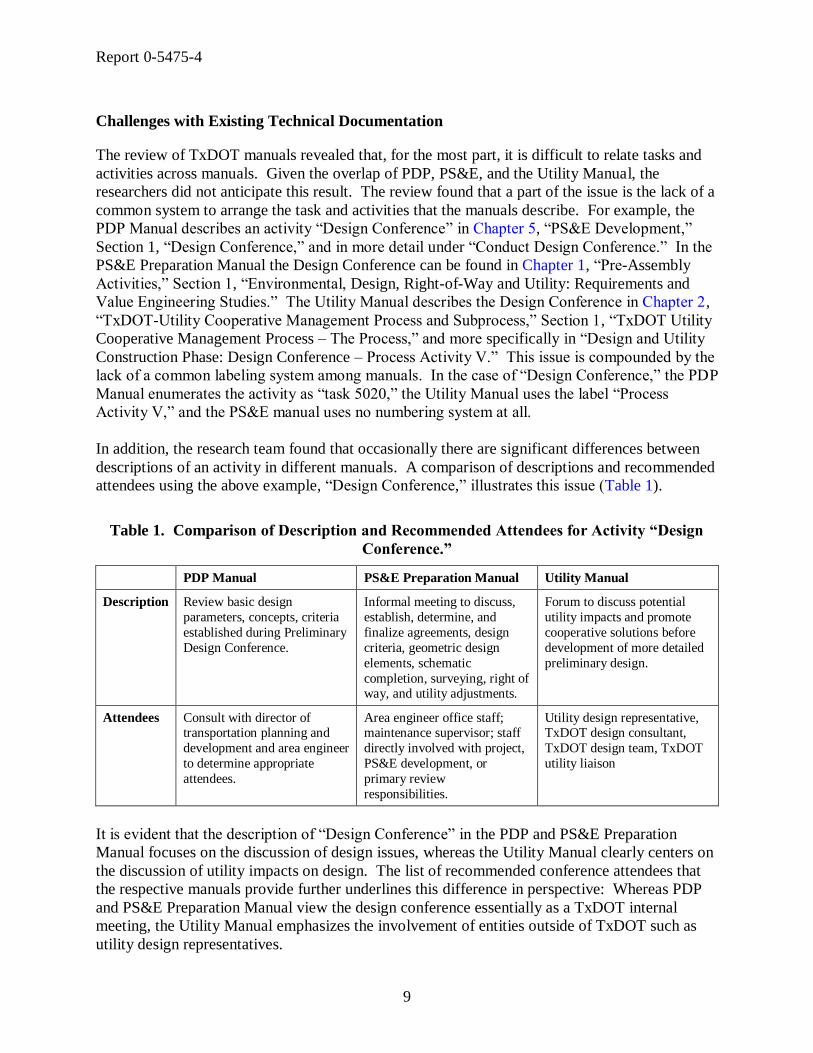
In addition, the research team found that occasionally there are significant differences between
descriptions of an activity in different manuals. A comparison of descriptions and recommended
attendees using the above example, ―Design Conference,‖ illustrates this issue (Table 1).
Table 1. Comparison of Description and Recommended Attendees for Activity “Design
Conference.”
PDP Manual PS&E Preparation Manual Utility Manual
Description Review basic design
parameters, concepts, criteria
established during Preliminary
Design Conference.
Informal meeting to discuss,
establish, determine, and
finalize agreements, design
criteria, geometric design
elements, schematic
completion, surveying, right of way, and utility adjustments.
Forum to discuss potential
utility impacts and promote
cooperative solutions before
development of more detailed
preliminary design.
Attendees Consult with director of transportation planning and
development and area engineer
to determine appropriate
attendees.
Area engineer office staff; maintenance supervisor; staff
directly involved with project,
PS&E development, or
primary review
responsibilities.
Utility design representative, TxDOT design consultant,
TxDOT design team, TxDOT
utility liaison
It is evident that the description of ―Design Conference‖ in the PDP and PS&E Preparation
Manual focuses on the discussion of design issues, whereas the Utility Manual clearly centers on
the discussion of utility impacts on design. The list of recommended conference attendees that
the respective manuals provide further underlines this difference in perspective: Whereas PDP
and PS&E Preparation Manual view the design conference essentially as a TxDOT internal
meeting, the Utility Manual emphasizes the involvement of entities outside of TxDOT such as
utility design representatives.

Report 0-5475-4
10
The shortage of information on the sequence and dependencies of tasks is a further limitation of
the PDP Manual for its use to develop a business process model. This is in part due to the
manual’s effort to cover many project types, complexities, and potential tasks. However, the
existing information about the sequence of tasks is incomplete at best. In its current version,
only some sections of the PDP Manual provide an overview of the section’s tasks along with just
a general statement about the sequence of tasks covered, such as ―these tasks may be performed
concurrently‖ or ―tasks are listed in approximate chronological order.‖ In addition, no section
overview contains information about sequencing of sections within a chapter, or the sequencing
of chapters and sections in relation to other chapters and sections of the manual. For example,
Section 4 of Chapter 4, ―Utility Adjustments,‖ contains five tasks that are ―listed in approximate
chronological order‖:
4610 Coordinate utility adjustment plans
4620 Prepare and execute utility adjustment agreements
4630 Utility owners adjust facilities
4640 Prepare utility clearance certifications
4650 Reimburse utility owners for eligible adjustment costs
The manual suggests an approximate chronological order, whereas in reality some tasks may
occur concurrently, may be skipped, or may be performed in a different sequence. There is also
no information about what pre-requisites are necessary for a task to start. Likewise, the manual
does not provide any information about how these tasks relate to tasks from other sections. For
example, there is no information on how task 4610, ―Coordinate utility adjustment plans,‖ relates
to task 4400, ―Obtain contractual agreements with local public agencies,‖ in Section 3 of the
same chapter. Similarly, the manual does not provide information about how sections from
different chapters relate to each other, for example how Section 4 of Chapter 5, ―Roadway
Design,‖ relates to Section 7, ―Drainage Design,‖ of the same chapter. There is also no
information about how ―Drainage Design‖ relates to ―Utility Adjustments,‖ which is Section 4 of
Chapter 4. Further, there is no information available about how chapters relate to each other, for
example how Chapter 4, ―Right of Way Utilities,‖ relates to Chapter 5, ―PS&E Development.‖
The underlying assumption that chapters and sections are listed in chronological order is not
always accurate, as is evident in the example of ―Right of Way Utilities‖ and ―PS&E
Development,‖ which entail for the most part concurrent activities.
The PDP Manual provides additional ―Critical Sequencing‖ information for about two-thirds of
all tasks. However, this information is mostly impractical because it is typically unrelated to
other tasks and does not reference task codes. Further, in some cases the information appears to
be incongruous, consisting of a warning rather than information on a critical sequence of events,
for example:
―Delays may occur without proper coordination with the MPO and other stakeholders.‖
―Request traffic data early.‖
―If the project remains idle for three years, a re-evaluation may be required.‖

Report 0-5475-4
11
In some cases, this information was also repetitiously added under the category ―Helpful
Suggestions.‖ In other cases, information provided in the ―Critical Sequencing‖ category
appeared to be a subtask, rather than information on task sequencing:
―During the environmental document development stage, the purpose and need statement
should be reviewed and updated as needed.‖
―Preliminary design can be as simple as a line diagram showing proposed number of
lanes, lane drops, and proposed overhead and large ground mounted, guide signs and
their proposed locations.‖
―Collect funding in accordance with provisions of the agreement.‖
In some cases, the sequencing information provided in this category was simply not very helpful
to determine a recommended sequence of events, for example:
―Revisions to the schematic are determined as the schematic is refined, hydraulic studies
are performed, and a detailed Level of Service analysis is done.‖
―Begin this task soon after determining its need to avoid project delay.‖
In summary, current sequencing information in the PDP Manual is sparse and limited to the
sequence of tasks within a section.
DATA MANAGEMENT-RELATED PRACTICES AND PLANS
Document Archival Processes
The Texas State Records Retention Schedule included in the Texas Administrative Code
documents minimum document retention schedules and requirements for state agencies (15). In
addition, each state agency must submit a complete records retention schedule to the State and
Local Records Management Division of the Texas State Library and Archives Commission.
This records retention schedule documents retention periods, security codes, archival location,
and medium (e.g., paper, microfilm, computer printout, electronic, or other) of record
classifications for a given division, section, or district (16). Typically, districts retain
construction and right of way project records for four years after closing a project (normally after
the engineer in charge has accepted delivery of the finished construction project). Utility
agreements, including utility agreements executed in districts using the local option, must be
retained as long as administratively valuable for engineering and legal reference, with a
minimum retention requirement of four years after project closing (16). After the retention
period, most original records may be destroyed except for the following types of right of way
documents (17):
right of way conveyances,
final right of way maps,

Report 0-5475-4
12
title insurance policies, and
other instruments pertaining to the state’s title to land or interests therein.
In the case of electronic records, both the Texas and district retention schedules require the
retention of documents for a minimum of four years after project closing (15). Retention of
electronic documents beyond the minimum number of years varies based on district, office, and
project manager practices. With new and anticipated initiatives such as FileNet® and
ProjectWise®, described in subsequent sections, it is likely that electronic document management
at TxDOT will become more structured, thereby facilitating project information access, querying,
and reporting.
INFORMATION SYSTEMS RELATED TO UTILITY ACTIVITIES IN THE PDP
TxDOT uses several information systems to support the project development process, including
DCIS and ROWIS. TxDOT districts have also developed information systems to help them with
routine activities, including the Highway Project Task Management System and the San Antonio
District Design and Construction Office (DCO) database. There are also several document
management strategies that districts and divisions have implemented or are in the process of
implementing. Of particular interest to this project are Bentley ProjectWise, DCIS, FileNet, and
the San Antonio District’s File Management System (FMS). A short description of systems
relevant to utility activities in the PDP follows.
Bentley ProjectWise
ProjectWise is an electronic document management system that allows users to manage various
project aspects. It is a client-server software application that runs on the Microsoft® Windows
®
platform with a similar look and feel of Microsoft Windows Explorer® (Figure 2). ProjectWise
is geared to the engineering field and was designed to work with Bentley MicroStation V8. Files
reside on a main server and are copied to a local drive for editing, which locks them for editing
on the main server. After editing, the edited file is placed back on the server, and the local file is
deleted to eliminate duplicate files. Like FileNet, ProjectWise manages files and provides
querying and reporting capabilities. Unlike FileNet, ProjectWise includes tools and templates to
automate the production of MicroStation drawings. It also retains the structure of MicroStation
reference files.

Report 0-5475-4
13
Figure 2. ProjectWise Sample Screenshots (18).
TxDOT is currently exploring the use of ProjectWise for management of engineering documents
such as MicroStation computer aided design (CAD) drawing files through pilot implementation.
TxDOT used ProjectWise successfully during the SH 130 design-build project in Central Texas,
which managed over 32,000 files using about 22 gigabyte (GB) of hard drive space (18).
TxDOT is evaluating the use of ProjectWise for engineering drawing file management. Efforts
related to data architectures, models, specifications, file structures, and naming convention are in
the early stages of development or have not yet started.
Design and Construction Information System
TxDOT uses the Design and Construction Information System to prepare projects for project
specification and estimation development, contract letting, and to track projects throughout the
project development process (19). The system contains project information such as work
descriptions, funding requirements, and dates for proposed activities. DCIS relies on a Tables
and Characteristics System (TACS) that contains lookup codes and project-specific files. DCIS
uses the control section job (CSJ) number to identify projects uniquely. Each project has
information in four key files as follows:
File 121 - DCIS project information,
File 122 - DCIS work program,

Report 0-5475-4
14
File 123 - DCIS project estimate, and
File 124 - DCIS contract letting.
Table 2 shows a sample of fields for each file. To access the system’s data, DCIS provides a
large number of project, contract, and utility screens that enable authorized users to complete
data inputs and updates, run queries, and create reports. The screens cover a wide range of topics,
including project identification and evaluation data, project planning and finance data, project
estimate data, and contract summary data. Figure 3 shows a copy of the DCIS project
identification screen.
Figure 3. DCIS Project Identification Screen (19).
DCIS has linkages with several TxDOT information systems, including the Bid Analysis
Management System/Decision Support System (BAMS/DSS), the Bid Proposal System (BPS),
the Contract Tracking System (CTS), the Subcontractor Monitoring System (SMS), and the
Construction and Maintenance Contract System (CMCS).

Report 0-5475-4
15
Table 2. Sample DCIS File Fields.
File 121 (DCIS-PROJECT-
INFORMATION)
File 122 (DCIS-WORK-
PROGRAM)
File 123 (DCIS-PROJECT-
ESTIMATE)
File 124 (DCIS-CONTRACT-
LETTING)
COMMON-DATA WORK-PROGRAM COMMON-DATA COMMON-DATA
CONTROL-SECT-JOB CONTROL-SECT-JOB CONTROL-SECT-JOB CONTRACT-CSJ
DISTRICT-NUMBER DISTRICT-NUMBER LAST-REVISION LAST-REVISION
LAST-REVISION DATE-LAST-REV USER-LAST-REV DATE-LAST-REV
DATE-LAST-REV TIME-LAST-REV DATE-LAST-REV TIME-LAST-REV
TIME-LAST-REV TOTAL-DATA TIME-LAST-REV RECORD-TYPE
REQUIRED-ID-DATA FIS-YEAR PLANS-ESTIMATE-DATA BIDITEM-SUMMARY-DATA
COUNTY-NUMBER YEARS-ACTIVE LINE-NUMBER BIDITEM-SEQUENCE-NO
HIGHWAY-NUMBER TOTAL-OBLIG-AMT CARD-TYPE ALTERNATE-GROUP-NO
PROJ-LENGTH TOTAL-ALLOC-AMT ALTERNATE-GROUP-NO BIDITEM-NO
CATEGORY DISTRICT-ARRAY25 BIDITEM-SPECPROV BIDITEM-DESC-CODE
ELIG-FED-FUND DIST-ALLOC-AMT BIDITEM-NO SPECIAL-PROV-NO
PROJ-CLASS DIST-OBLIG-AMT BIDITEM-DESC-CODE SPECIAL-ACCT-NO
MANAGER-NUMBER CZ-FILLER-FIELD SPECIAL-PROV-NO QUANTITY
EST-CONST-COST STATE-TRANS-IMPRV-PGM-
GRP
BIDITEM-REF-NO ESTIMATED-PRICE
DATE-EST-COST STIP-MPO-CODE SPCL-000-PROV-TEXT DUP-PRICE-INDICATOR
AUTO-LINE-NUMBER STIP-FY SPECIAL-ACCT-NO BIDDER-CONTROL-DATA
TYPE-OF-WORK STIP-PROJECT-ID ENG-QUANTITY BIDDER-SEQNO
LIMITS-FROM STIP-PROJECT-NBR ENG-ESTIMATE-PRICE TOTAL-BID
LIMITS-TO STIP-PHASE-CODE UNIT-PRICE VERIFY-CODE
LAYMAN-DESCRIPTION1 STIP-FEDERAL-COST-PCT BIDITEM-FLAG BIDDER-RANKNO
LAYMAN-DESCRIPTION2 STIP-STATE-COST-PCT BIDITEM-DESCRIPTION INCOMPLETE-FLAG
BEG-MILE-POINT STIP-LOCAL-
CONTRIBUTIONS-AMT
UNIT-WORK VENDOR-NOS
END-MILE-POINT STIP-LOCAL-COST-PCT COMMENT BI-SEQNO-DISCREP31
OPTIONAL-ID-DATA STIP-EST-CONSTRUCTION-
AMT
CATGWORK-DESC BIDITEM-ALT-FLAG9
CONTRACT-CSJ STIP-FUNCTIONAL-CLASS-
CODE
CATGWORK-MILES BIDITEM-ALT-FLAG
PROJ-SUSP STIP-STATE-CATEGORY-CODE FUND-SOURCE-GROUP3 BIDITEM-DETAIL-11
PRIORITY-CODE STIP-DISTRICT-EST-LET-DATE FUND-SOURCE UNIT-PRICE
PDP-LET-DATE STIP-EXISTING-LANE-AMT PERCENT-PART BID-AMOUNT
DIST-LET-DATE STIP-PROPOSED-LANE-AMT BRIDGE-COST-DATA ALTERNATE-GROUP
ORIGINAL-PLANNED-LET-
DATE
STIP-PROJECT-LENGTH-MEAS BRIDGE-LENGTH-EXISTING BI-INCOMPLETE-FLAG
DIST-LET-CHANGES-NBR STIP-LOCATION-FROM-DESC BRIDGE-LENGTH-PROPOSED CONTRACT-SUMMARY
APPRVD-LET-DATE STIP-LOCATION-TO-DESC BRIDGE-WIDTH-EXISTING CONTRACT-NUMBER
ACTUAL-LET-DATE STIP-LAYMANS-DESC BRIDGE-WIDTH-PROPOSED WORKING-DAYS
BACKLOG-PROJ STIP-PROJECT-CMNT BRIDGE-REMOVAL-
BREAKBACK
LETTING-STATUS-CODE
EST-ROW-COST STIP-REVISION-DATE OLD-NBI-NUMBER RECEIVED-UNTIL-TIME
DATE-EST-ROW STIP-LOCK-FLAG NEW-NBI-NUMBER RECEIVED-UNTIL-DATE
RA-FLAG STIP-IMPLEMENT-AGENCY-
CMNT
BRIDGE-WORK-TYPE ENGINEER-INFO
OTHER-PART STIP-PROGRAM-COST OLD-BRIDGE-TYPE ENG-NO
PROJECT-NUMBER STIP-APPORTIONMENT-CODE NEW-BRIDGE-TYPE ENG-NAME
CONST-COMP STIP-FEDERAL-COST-TOTAL ROADWAY-CLEAR-WIDTH ENG-ADDRESS
PSE-COMP STIP-STATE-COST-TOTAL BRIDGE-NAME ENG-CITY
ROW-COMP STIP-LOCAL-COST-TOTAL BRIDGE-SYSTEM-ID ENG-ZIPCODE
HIGHWAY-SYSTEM STIP-PROJ-LENGTH-METRIC BRDG-COST-GRP ENG-PHONE
REMARKS STIP-FHWA-APPROVAL-DATE BRDG-LENGTH MBE-WBE-FLAG
MISCELLANEOUS-FIELDS MINUTE-ORDER-GRP BRDG-NBI-NUMBER PROPOSAL-GUARANTY-AMT
DIST-ENG-EST MINUTE-ORDER-NBR BRDG-WORK-TYPE WAIVER-FLAG
D8-ENG-EST MINUTE-ORDER-DATE BRDG-TYPE DIVISION-RESPONSIBLE
MISC-COST MINUTE-ORDER-REMARKS BRDG-SYSTEM-ID INCLUDED-PROJECTS191
PROJ-BID-AMOUNT BRDG-DECK-AREA COMBINED-FLAG191

Report 0-5475-4
16
FileNet
FileNet is an enterprise content management system that enables users to share and manage
access to files, generate database records to keep track of all documents processed, and produce
queries and reports based on a number of attributes (20). FileNet resides on top of a database
management system (DBMS) such as Oracle®
, IBM® DB2
®, or Microsoft Structured Query
Language (SQL®) Server.
The Houston District started using FileNet in 1996 to track construction project as-built drawings,
PS&E documents, and correspondence. TxDOT is currently implementing FileNet statewide
using a separate implementation for each business unit within the organization. TxDOT’s goal is
to move from ad hoc procedures for managing electronic documents to a standard recordkeeping
system for document management (21). The TxDOT implementation stores document-related
data in a centrally located Microsoft SQL Server database. The database also contains pointers
to files that are physically stored on a dedicated server at every business unit where TxDOT has
implemented FileNet. Currently, TxDOT uses two FileNet configurations: a ―thick-client‖
configuration, which requires a client application on user computers, and a ―thin-client‖
configuration called TxDocsOnline, which is web based and uses a browser to interact with the
database and the FileNet file server. The ―thick-client‖ provides an interface similar to the
Microsoft Windows Explorer® interface, with additional functionality, such as viewing current
file users, assigning file attributes or tags, querying, searching, and file versioning (Figure 4).
The TxDOT FileNet implementation does not support viewing Geographic Information System
(GIS) or CAD documents, although this functionality is possible through third-party programs
(22).
TxDOT’s experience with the initial implementation of FileNet has led to the development of a
TxDOT specific archiving standard described in the Content Services Library Standards
document (22). This standard aims to facilitate the use and implementation of FileNet and
describes the standards for FileNet libraries consisting of document classes, security parameters,
folder settings, standard properties, and document properties. In addition, the standard provides
appendices with property definitions, recommended property values, recommended record types,
and document types for standard document classes.
In the TxDOT FileNet implementation, libraries represent the structure each business unit
chooses to organize documents. For example, there is a library for Motor Carrier Division
documents, a separate library for Finance Division documents, and so on. There is also a library
for districts (organized around functional areas), which TxDOT developed using lessons learned
from the Houston District’s experience with FileNet. The Houston District organized its FileNet
implementation around projects. According to TxDOT officials, one of the reasons to develop a
―standard‖ district library around functional areas instead of projects was that a structure based
on functional areas could reduce document redundancy more effectively. A potential
disadvantage of this approach is the risk of losing the ―natural‖ linkage that exists among
documents that pertain to the same project. To reduce this risk, the CSJ number is a mandatory
attribute for project-related documents in FileNet.

Report 0-5475-4
17
Figure 4. FileNet Sample Screenshots (23).
Following the Electronic Document Technologies Implementation and Support (EDTIS) Project
Content Services library standards, FileNet uses document classes, record types, and document
types to organize documents in libraries (22, 24). Document classes represent the highest folder
aggregation level, with one document class per library (Table 3). Document classes have record
types, and record types have document types.

Report 0-5475-4
18
Table 4 shows a sample of record types for document type 15, ―Right of Way,‖ that pertains to
utility conflict management. Each document class, record type, and document type has a
numerical code (e.g., 13 for document class ―Right of Way,‖ 2 for record type ―Easements,‖ and
3 for document type ―Drainage Easements‖). The combination of the three numerical codes is a
unique file code (e.g., 13.2.3) that represents a unique document class/record type/document type
combination. Notice that the relationship between document classes and their corresponding
numerical codes is one to one, which is not necessarily true for record types or document types.
For example, the same record type may have different numerical codes in different document
classes. This situation makes it more difficult to use generic lookup tables that index record
types and document types to specify the file code.
Table 3. Document Classes in the TxDOT FileNet Implementation (Adapted from 22).
Document
Class Code Document Class
Document
Class Code Document Class
1 Administrative 10 Occupational Safety
2 Construction 11 Project Development and Design
3 Contracts Leases and Agreements 12 Purchasing and Warehouse
4 Environmental Operations 13 Right of Way
5 Equipment and Facilities 14 Traffic Operations
6 Finance 15 Transportation Planning
7 Human Resources 16 Travel and Public Information
8 Information Systems 17 Incoming Mail
9 Maintenance Operations 18 WebXtra Document

Report 0-5475-4
19
Table 4. Sample of Record Types and Document Types of the “Right of Way” Document
Class (Adapted from 22).
Document
Class Record Type Document Type
File
Code
Right of Way Certifications Utility 13.1.4
Right of Way Easements Drainage Easement 13.2.3
Right of Way Easements Release of Easement 13.2.4
Right of Way Easements Request for Easement 13.2.5
Right of Way Easements Temporary Easement 13.2.6
Right of Way ROW Map Map 13.12.1
Right of Way ROW Releases Funding 13.13.1
Right of Way ROW Releases Map 13.13.2
Right of Way ROW Releases Minute Order 13.13.3
Right of Way ROW Releases Payment 13.13.4
Right of Way ROW Releases Property Description and Plat 13.13.5
Right of Way ROW Releases Resolution 13.13.6
Right of Way ROW Releases ROW Release 13.13.7
Right of Way ROW Releases Schematic 13.13.8
Right of Way Utility Accommodation Adjustment 13.18.1
Right of Way Utility Accommodation Affidavit 13.18.2
Right of Way Utility Accommodation Compensable Interest Certificate 13.18.3
Right of Way Utility Accommodation Consultant Contract Review 13.18.4
Right of Way Utility Accommodation Correspondence 13.18.5
Right of Way Utility Accommodation Cost Estimate 13.18.6
Right of Way Utility Accommodation Date of Eligibility Request 13.18.7
Right of Way Utility Accommodation Determination of Eligibility 13.18.8
Right of Way Utility Accommodation Funding 13.18.9
Right of Way Utility Accommodation Layout Schematic or Drawing 13.18.10
Right of Way Utility Accommodation Letter of Authority 13.18.11
Right of Way Utility Accommodation Meeting Minutes and Notes 13.18.12
Right of Way Utility Accommodation Notice or Notification 13.18.13
Right of Way Utility Accommodation Plan 13.18.14
Right of Way Utility Accommodation Relocation 13.18.15
Right of Way Utility Accommodation Specification 13.18.16
Right of Way Utility Accommodation SUE Deliverable 13.18.17
Right of Way Utility Accommodation SUE Media Information Form 13.18.18
Right of Way Utility Accommodation Survey 13.18.19
Right of Way Utility Accommodation Utility Conflict Check 13.18.20
Right of Way Utility Accommodation Utility Coordination 13.18.21
Right of Way Utility Accommodation Utility Easement 13.18.22
Right of Way Utility Accommodation Utility Exception Request 13.18.23
Right of Way Utility Accommodation Utility Standard Sheet 13.18.24
Highway Project Task Management System
DCIS contains a wealth of information but resides on a mainframe in a format that limits the
access of potential users. The Corpus Christi District has developed a Microsoft Access-based
application, called HPTMS, to interact with DCIS. The system is able to download data from
DCIS and transfer it to a relational database management system (RDBMS) using Statistical
Analysis Software (SAS) scripts. However, the connection operates only in one direction; there
is no upload link that would enable HPTMS to upload or update DCIS data. The system allows
the user to generate various reports, such as project development schedule, list of projects to be
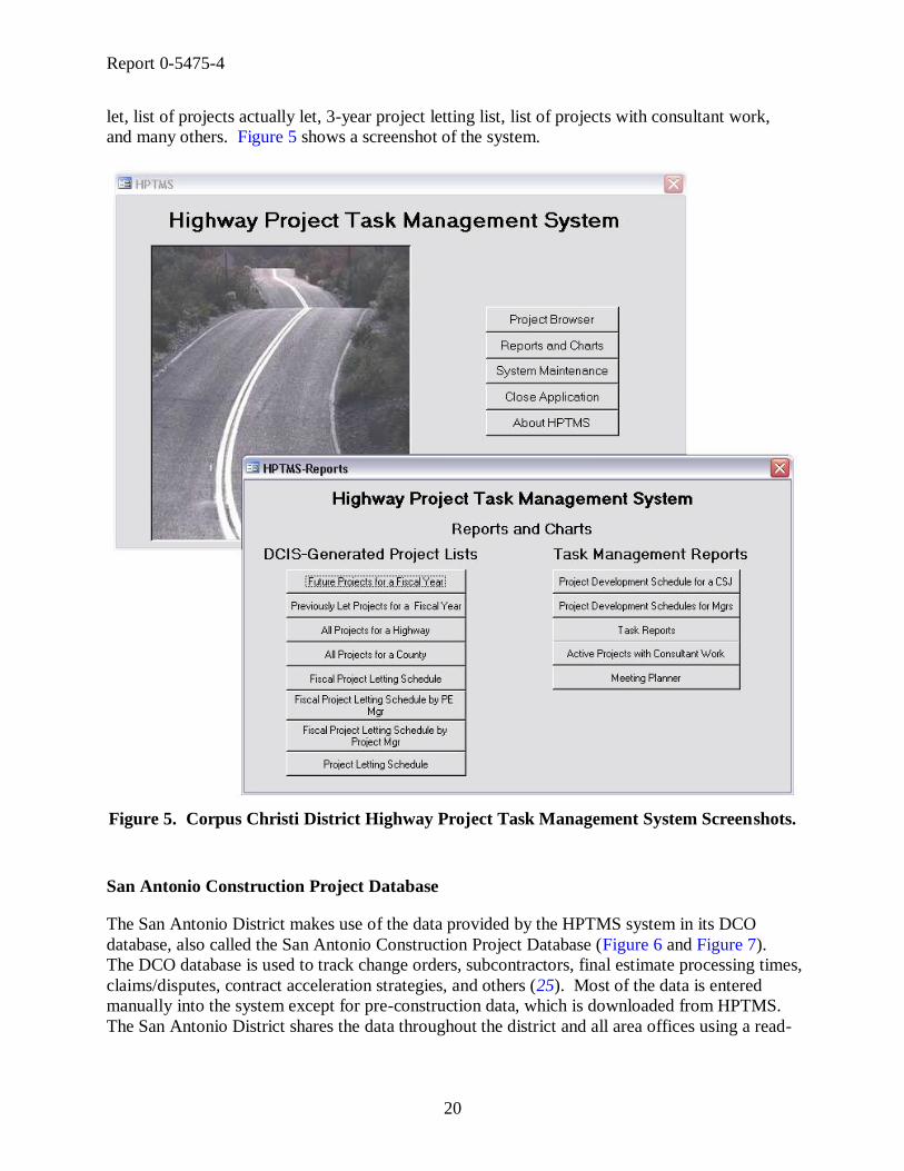
Report 0-5475-4
20
let, list of projects actually let, 3-year project letting list, list of projects with consultant work,
and many others. Figure 5 shows a screenshot of the system.
Figure 5. Corpus Christi District Highway Project Task Management System Screenshots.
San Antonio Construction Project Database
The San Antonio District makes use of the data provided by the HPTMS system in its DCO
database, also called the San Antonio Construction Project Database (Figure 6 and Figure 7).
The DCO database is used to track change orders, subcontractors, final estimate processing times,
claims/disputes, contract acceleration strategies, and others (25). Most of the data is entered
manually into the system except for pre-construction data, which is downloaded from HPTMS.
The San Antonio District shares the data throughout the district and all area offices using a read-

Report 0-5475-4
21
only version of the database. The San Antonio District plans to expand the DCO database to
transfer construction data from SiteManager in the future.
Figure 6. San Antonio District DCO Database Screenshot (25).
Figure 7. San Antonio District DCO Database “Project Data Entry” Screenshot (25).

Report 0-5475-4
22
Plans Online
Plans Online is a web-based application that TxDOT uses to manage the storage, archival, and
delivery of project plans and related documentation to internal and external users (26). Project
documents typically include letting, contract, and final/as-built plans; proposals; project addenda;
and bid tabs. Internet access to Plans Online is limited to letting documents for construction and
maintenance projects over a five-month period: the current month, the next month, and the prior
three months. Plan sheets are available in two formats: tagged image file (TIF) and portable
document format (PDF). Internet access also includes post-letting bid tabulation and bid total
data for a three-month period: the current month and the previous two months. By comparison,
Intranet access to Plans Online is much more comprehensive and includes pre-letting, post-
letting, and archived documents and data. TxDOT maintains a permanent archive of as-built
plans (in digital format – TxDOT does not archive the original Mylar plans that divisions
provide). In addition, TxDOT maintains a 10-year archive of letting database records.
Plans Online includes a Captaris Alchemy® viewer that enables users to browse through database
contents in a folder hierarchy (Figure 8). The viewer also enables users to run queries by project
attributes, document attribute fields, document content, file name, folder attribute fields, and
document annotations. As a reference, Table 5 includes the list of project and document
attributes in Plans Online. To populate these attributes, TxDOT follows a standardized
procedure that involves scanning and indexing documents. For indexing, TxDOT uses optical
character recognition (OCR) software to extract document titles from sheet index plan images.
The process also includes manually cleaning these titles and importing the resulting data into the
database.
Currently, TxDOT is evaluating platforms for upgrading Plans Online, including the
implementation of a GIS-based interface to facilitate document querying and viewing.
Table 5. Plans Online Project and Document Attributes (26).
Project Attributes Document Attributes
Controlling CSJ Number (CCSJ) Limits From Document Title
County Name Limits To File Name
District Name Reference Marker From Sheet Number
Job Type Reference Marker To CCSJ Number
Job Class Description of Project Letting Year
Other CSJs Letting Month Letting Month Project Number Letting Day
Highway Number Letting Year

Report 0-5475-4
23
Figure 8. Plans Online Interface (26).
Right of Way Information System (ROWIS)
The ROW Division implemented ROWIS in 1997 to track and report financial data of property
acquisitions throughout the right of way acquisition process (27). The system enables users to
capture, track, and report on property acquisition processes such as right of way parcel
development during negotiations, settlements, or eminent domain proceedings. Although
ROWIS was not designed to accommodate the utility coordination process, the Right of Way
Division currently uses ROWIS to track reimbursable utility agreement payments by creating
parcel records in ROWIS to represent utility agreements. Figure 9 is a screenshot of the ROWIS
application.

Report 0-5475-4
24
Figure 9. ROWIS Screenshot.
ROWIS runs on a Microsoft SQL Server database platform. Table 6 provides a listing of
ROWIS database tables. Figure 10 shows a high-level representation of the ROWIS logical data
model that only includes the most relevant entities. The system interface includes screens to
display or query data on topics such as projects, parcels, tasks, owners, CSJ numbers, minute
orders, and public agencies. A description of the core entities in ROWIS (Parcels, Projects, and
Control Section Jobs) follows:
Parcels. The Parcels entity contains attributes that describe property parcels, such as
description, appraised value, acquisition status, and several dates including possession date,
parcel release date, and total paid date. The primary key in Parcels is Parcel ID (which is
also a foreign key in entities Projects, Agencies, Control Section Jobs, and Associates).
Projects. The Projects entity includes attributes that characterize a project including
project type code, beginning and ending limits, project CSJ, right of way CSJ, and several
date attributes such as estimated letting date or right of way clearance date. The primary
key in Projects is Project ID (which is not the same as project CSJ or right of way CSJ).
Project ID is a foreign key in entities Parcels, Control Section Jobs, and Agencies. In
Projects, the right of way CSJ and right of way account number attributes are inversion
entry keys (i.e., they are frequently accessed non-unique attributes).
Control Section Jobs. The Control Section Jobs entity includes attributes that provide
additional information about projects, including project CSJ, CSJ type, project limits, and
federal funding eligibility. The primary key in Control Section Jobs is CSJ ID, which is

Report 0-5475-4
25
not the same as the project CSJ. CSJ ID provides a linkage between Control Section Jobs
and Parcels through the many-to-many entity Control Section Jobs Parcels.
Table 6. List of Database Tables in ROWIS.
AGENCIES INVOICES PBCATVLD
APPRAISALS INVOICES TASKS PROJECTS
APPRAISED ITEMS LEGAL NAMES PRSNL PROP MOVES
ASSOCIATES LOGIC DRILLDOWN QUALIFICATIONS
ASSOCIATES DISTRICTS LOGIC HELP RENTAL SUPPLEMENTS
ASSOCIATES TASKS LOGIC LINK REPORTS SCHEDULED
ASSOCTASK DISPLACEE LOGIC SEARCH RESIDENTIAL MOVES
AUDIT LOG LOGIC WINDOW ROWIS STATS
CACHE CONTROL LOGIC WINDOW CONTROL SECURITY APPS
COMMENTS MAP SHEET INDEX SECURITY GROUPINGS
COMPONENTS MESSAGES SECURITY INFO
CONTROL SECTION JOBS MINUTE ORDERS SECURITY TEMPLATE
CONTROL SECTION JOBS PARCELS MINUTE ORDERS PARCELS SECURITY USERS
DISPLACEE MINUTE ORDERS PROJECTS SEGMENTS
DISPLACEE DOCUMENTS NEW ROWIS LOGINS SEQUENCE NBRS
DOCUMENTS NON RESIDENTIAL MOVES STATUS VALUES
ENCUMBRANCES PARCELS TASKS
ESTIMATED EXPENSES PARTICIPATING AGENCIES TEMP ASSOCIATES TASKS REF
EVENT HISTORY PARTICIPATING AGENCIES DEPOSIT TEMP OWNER REFERENCE
EXP CATG CD PARTICIPATING AGENCIES PARCELS TEMP PARCEL REFERENCE
EXP TYPE CD PAYMENT ERRORS TEMP PROJ PARCEL REFERENCE
FORMS PAYMENTS TXDOT DISTRICTS
HOUSING SUPPLEMENTS PBCATCOL TYPE CODES
IMPROVEMENTS PBCATEDT WORKORDERS
INTEREST OWNERS PBCATFMT WORKORDERS TASKS
INTEREST OWNERS ITEMS PBCATTBL
Control Section Jobs
Participating Agencies Parcels Agencies
Associates
Interest Owners Items
Participating Agencies Deposit
Parcels
Associates Tasks
TxDOT DistrictsInterest Owners
Participating Agencies
Minute Orders
Associates Districts
Segments
Assoctask Displacee
Improvements
Minute Orders Parcels
Components
Appraisals
Displacee
Security Users
Minute Orders Projects
Event HistoryProjects
Appraised Items
Control Section Jobs Parcels
Figure 10. ROWIS High-Level Logical Data Model.

Report 0-5475-4
26
ROWIS uses data produced and managed in DCIS, such as CSJ numbers, federal project number,
project limits, and authorized funds. ROWIS is not integrated with DCIS, which means that
DCIS data must be manually entered into ROWIS. Data synchronization issues arise when there
are data updates in DCIS, since a ROWIS project manager must make the same change in
ROWIS manually.
The main function of ROWIS is to support TxDOT’s right of way acquisition process. It
provides very little support for the management and inventory of right of way assets after the
conclusion of the acquisition process. In addition, ROWIS does not have functionality to display
(or to provide a link to) right of way parcels or utility adjustments on a map. In fact, the Parcels
entity in ROWIS does not contain any spatial data except for a general description of the
physical location of the parcel. ROWIS is not compatible with the GIS Architecture and
Infrastructure Project (GAIP) and cannot make data available to TxDOT users through Main
Street Texas (MST).
For the development of the prototype utility conflict management system, the researchers
envision a connection of the data architecture with ROWIS to enable data sharing and reduce
data redundancy. The link between the two architectures is an entity called ROWIS
CONNECTION, which minimizes the need for changes to the ROWIS architecture. The Project
Subject Area in Chapter 5 provides a more detailed discussion of this construct.
Right of Way Division Utility Agreement Database
The Utility Agreement Database (UAD) is a Microsoft Access database the TxDOT ROW Division
uses to track payments and billings associated with utility agreements of reimbursable utility
adjustments. The TxDOT ROW Division developed the UAD as a temporary solution to provide
capabilities to track billing information for reimbursable utility agreements that are currently not
implemented in ROWIS. Although the UAD is an extension of functionality that ROWIS does not
currently provide, there are no physical connections between the two systems. As such, any project,
parcel, or owner-related information must be manually duplicated in the UAD.
The ROW Division provided a copy of the database to the research team. The researchers
analyzed the database and created a logical data model of the database in Computer Associates®
AllFusion ERwin®
Data Modeler (now available as CA® ERwin
® Data Modeler) (Figure 11).
The researchers then modified the data model to ensure compliance with TxDOT data
architecture standards. In the last step, the researchers integrated the standard compliant model
into the logical data model of the prototype system for the management of utility conflict data
called Utility Accommodation and Conflict Tracker (UACT).
The UACT data model provides the complete functionality of the UAD that is currently in use at
the ROW Division. As a result, a future implementation of UACT would render the UAD
obsolete. However, this does not address the issue that currently, some of the billing data related
to utility agreements must be entered both into ROWIS and into the UAD. Depending on the
level of integration that will be feasible between UACT and ROWIS, billing and payment data
should only be entered in one of the two systems and then referenced and displayed in the other
as needed.

Report 0-5475-4
27
UTILITY BILLING LOG
UTILITY BILLING RECORD
U NUMBER
UTILITY BILLING DATE IN
UTILITY BILLING DATE OUT
UTILITY BILLING NO
UTILITY BILLING AMOUNT
UTILITY BILLING COMMENTS
UTILITY BILLING REVIEWER
DISTRICT
UTILITY NAME
PROJECT NUMBER
PROJECT CSJ
ADMINISTRATIVE CITATION
CLOSEOUT
UTILITY CLOSEOUT ROW ACCOUNT NUMBER
UTILITY CLOSEOUT COUNTY
UTILITY CLOSEOUT CSJ
UTILITY CLOSEOUT UNUMBER LIST
UTILITY CLOSEOUT DATE PROCESSED
UTILITY CLOSEOUT REVIEWER
COUNTY
COUNTY NAME
COUNTY NUMBER
DISTRICT NUMBER
COUNTY TYPE
DISTRICT
DISTRICT NAME
DISTRICT NUMBER
DISTRICT ABBREVIATION
EXCEPTION TYPE
EXCEPTION TYPE NAME
EXCEPTIONS
EXCEPTION NUMBER
EXCEPTION UTILITY NAME
EXCEPTION COUNTY NUMBER
EXCEPTION ROW CSJ NUMBER
EXCEPTION CONSTRUCTION CSJ NUMBER
EXCEPTION ROW ACCOUNT NUMBER
EXCEPTION HIGHWAY NUMBER
EXCEPTION LIMITS FROM
EXCEPTION LIMITS TO
EXCEPTION TYPE
EXCEPTION APPROVED
EXCEPTION REVIEWER
EXCEPTION COMMENTS
FIMS IDENTIFIER
FIMS ID
NON REIMBURSABLE UJUA
UTILITY UJNR RECORD NUMBER
UTILITY UJNR UNUMBER
UTILITY UJNR REVIEWER
UTILITY UJNR NAME
UTILITY UJNR ROW NUMBER
UTILITY UJNR CSJ NUMBER
UTILITY UJNR DISTRICT
UTILITY UJNR HIGHWAY
UTILITY UJNR LIMITS FROM
UTILITY UJNR LIMITS TO
UTILITY UJNR DATE IN
UTILITY UJNR DATE OUT
UTILITY UJNR APPROVAL DATE
UTILITY UJNR TYPE ADJUSTMENT
UTILITY UJNR RETURN DISTRICT
UTILITY PARK
UTILITY PARK RECORD
UNUMBER
UTILITY PARK DATE IN
UTILITY PARK DATE OUT
UTILITY PARK CODE
UTILITY PARK COMMENTS
UTILITY PARK REVIEWER
UTILITY PARK DISTRICT
UTILITY PARK UTILITY NAME
UTILITY PARK CODE
UTILITY PARK CODE
UTILITY REVIEWER
UTILITY REVIEWER ID
ROW CONTRACT TYPE
ROW CONTRACT TYPE ID
ROW CONTRACT TYPE NAME
ROW FUNDING TYPE
ROW FUNDING TYPE NAME
ROW PROJECT
ROW ACCOUNT NUMBER
HIGHWAY NUMBER
ROW CSJ NUMBER
ROW RELEASE DATE
ROW FUNDING
ROW AP DATE
FIMS IDENTIFIER
ROW COMMENTS
ROW CONTRACT DATE
ROW CONTRACT TYPE
ADJUSTMENT TYPE
UTILITY ADJUSTMENT TYPE NAME
UTILITY ADJUSTMENT CODE
UTILITY ADJUSTMENT TYPE REVIEW NEED
COUNTY TYPE
COUNTY TYPE ID
UTILITY
REVIEWER
UNUMBER
UTILITY NAME
TYPE OF COUNTY
COUNTY
ROW ACCOUNT 1
ROW ACCOUNT 2
ROW CSJ1
ROW CSJ2
CONSTRUCTION CSJ
BILLED AMOUNT
ROW 120 ESTIMATE
INITIAL ESTIMATE
INITIAL ESTIMATE DATE
AGREEMENT ESTIMATE
EXCEPTION AMOUNT
TOTAL PAID
BETTERMENT PERCENT
SALVAGE GIVEN
ELIGIBILITY RATIO
ROW CHARGES
DATE OF ELIGIBILITY
ROW RECEIVE DATE
ROW RECEIVE YEAR
REVIEW BEGIN DATE
ROW APPROVAL DATE
BILL RECEIVE DATE
AUDIT TRANSFER DATE
AUDIT DATE
PRIOR RIGHT
REIMBURSABLE ADJUSTMENT FLAG
UJUA NEED FLAG
QUITCLAIM NEED FLAG
UAR EXCEPTION DATE
UAR EXCEPTION FLAG
FORM 48 NEED FLAG
CTUC FLAG
CONSULTANT CHARGES FLAG
COMMENT
FINAL PAYMENT DATE
ADJUSTMENT TYPE
ADJUSTMENT CODE
COMPANY CODE
COMPANY MAIL CODE
CONSULTANT CHARGES
ROW CHARGES AMOUNT
ESTIMATED SALVAGE AMOUNT
UJUA APPROVAL DATE
PAYMENT AMOUNT 1
PAYMENT AMOUNT 2
PAYMENT AMOUNT 3
PAYMENT AMOUNT 4
PAYMENT AMOUNT 5
PAYMENT AMOUNT 6
PAYMENT DATE 1
PAYMENT DATE 2
PAYMENT DATE 3
PAYMENT DATE 4
PAYMENT DATE 5
PAYMENT DATE 6
PAYMENT AMOUNT FISCAL YEAR 1
PAYMENT AMOUNT FISCAL YEAR 2
PAYMENT AMOUNT FISCAL YEAR 3
PAYMENT AMOUNT FISCAL YEAR 4
PAYMENT AMOUNT FISCAL YEAR 5
PAYMENT AMOUNT FISCAL YEAR 6
DISTRICT APPROVAL NUMBER
UPPER LIMIT AMOUNT
UPPER LIMIT DATE
EXCEPTION RECEIVE DATE
EXCEPTION RESOLUTION DATE
RETURN DISTRICT DATE
HIGHWAY NUMBER
DATE OF ELIGIBILITY ESTIMATE DATE
DATE OF ELIGIBILITY COST ESTIMATE AMOUNT
ESTIMATE AGREEMENT DATE
ADJUSTMENT START DATE
ESTIMATED ELIGIBILITY RATIO AT DATE OF ELIGIBILITY NUMBER
CONSTRUCTION PROJECT LETTING DATE
ACTUAL AGREEMENT SUBMITTAL DATE
ACTUAL ADJUSTMENT COMPLETION DATE
ALTERNATE PROCEDURE DATE
DATE OF ELIGIBILITY FISCAL YEAR 1 NUMBER
DATE OF ELIGIBILITY FISCAL YEAR 1 ESTIMATE AMOUNT
DATE OF ELIGIBILITY FISCAL YEAR 2 NUMBER
DATE OF ELIGIBILITY FISCAL YEAR 2 ESTIMATE AMOUNT
DATE OF ELIGIBILITY FISCAL YEAR 3 NUMBER
DATE OF ELIGIBILITY FISCAL YEAR 3 ESTIMATE AMOUNT
DATE OF ELIGIBILITY FISCAL YEAR 4 NUMBER
DATE OF ELIGIBILITY FISCAL YEAR 4 ESTIMATE AMOUNT
DATE OF ELIGIBILITY ALL FISCAL YEAR TOTAL AMOUNT
TOTAL AGREEMENT ESTIMATE FISCAL YEAR 1 AMOUNT
TOTAL AGREEMENT ESTIMATE FISCAL YEAR 1 ESTIMATE AMOUNT
TOTAL AGREEMENT ESTIMATE FISCAL YEAR 2 AMOUNT
TOTAL AGREEMENT ESTIMATE FISCAL YEAR 2 ESTIMATE AMOUNT
TOTAL AGREEMENT ESTIMATE FISCAL YEAR 3 AMOUNT
TOTAL AGREEMENT ESTIMATE FISCAL YEAR 3 ESTIMATE AMOUNT
TOTAL AGREEMENT ESTIMATE FISCAL YEAR 4 AMOUNT
TOTAL AGREEMENT ESTIMATE FISCAL YEAR 4 ESTIMATE AMOUNT
TOTAL AGREEMENT ESTIMATE ALL FISCAL YEAR TOTAL AMOUNT
FISCAL YEAR 1 BILLED AMOUNT
FISCAL YEAR 1 BILLED AMOUNT 2
FISCAL YEAR 2 BILLED AMOUNT
FISCAL YEAR 2 BILLED AMOUNT 2
FISCAL YEAR 3 BILLED AMOUNT
FISCAL YEAR 3 BILLED AMOUNT 2
FISCAL YEAR 4 BILLED AMOUNT
FISCAL YEAR 4 BILLED AMOUNT 2
ALL FISCAL YEAR TOTAL BILLED AMOUNT
SUBSEQUENT ENCUMBRANCE NUMBER
FEDERAL ROW PROJECT NUMBER
SALVAGE AMOUNT
LATEST ESTIMATE AMOUNT
LATEST ESTIMATE DATE
ACCRUED DEPRECIATION AMOUNT
ADJUSTMENT DURATION DAYS NUMBER
REIMBURSABLE ADJUSTMENT DATE
UJUA NEED DATE
QUITCLAIM NEED DATE
UTILITY CLOSED DATE
DISTRICT NAME (FK)
UTILITY COMPANY
UTILITY COMPANY NAME
Figure 11. ROW Division Utility Agreement Database Data Model.

Report 0-5475-4
28
San Antonio District File Management System
The San Antonio District FMS is a systematic arrangement of folders, files, and procedures to
create uniformity in project development and documentation (28). FMS includes a project folder
structure, primary and secondary project files, MicroStation libraries, and embedded quantity
spreadsheets, which link quantity estimate spreadsheets to CAD files with quantity summaries.
FMS relies on a file manager to maintain the integrity of the project files. This manager reviews
and incorporates all work into the primary files, maintains backups, and coordinates multi-user
project development. The manager is the only person who accesses and makes changes to the
primary files.
FMS stores all electronic files associated with a project in a root folder with the project’s CSJ
number. Each CSJ folder contains 25 subfolders that sort project files into functional areas, such
as pavement design, roadway, standards, survey, traffic control plan, etc. For each project, there
are 11 primary files, which are files that are attached as references to the secondary files
(Table 7). To minimize erroneous modifications, only the file manager can access the primary
files.
Table 7. FMS Primary File Types (28).
Primary File Abbreviation Purpose
Map map existing topography
Roadway rdwy surface improvements
Horizontal Alignment haln horizontal control
Vertical Alignment valn vertical control
Drainage drn subsurface improvements
Utility util existing and proposed utilities
TCP–SW3P tcp–sw3p traffic control and pollution control items
Traffic traf proposed pavement markings, signs, signals, and illumination
Border bord sheet border with title block and legends
Pattern patt patterns and or shading to differentiate project aspects
Quantity Box qbox linked plan sheet quantity boxes and summaries
Texas Reference Marker System
The Texas Reference Marker (TRM) System is a mainframe-based system that documents
physical and performance characteristics of the state-maintained highway network using the
statewide reference marker network (Figure 12) as a geo-referencing tool (29). With TRM, the
location of features on the ground is defined in terms of mileage displacement from the nearest
marker. TRM is centerline based, although it does provide for the identification of features on
either side of the centerline. Although TRM relies on displacement from markers as the
mechanism to reference features to the highway network, the system also enables the calculation
of cumulative distances by using the relative location of the markers along the highway network.
This conversion enables the production of maps documenting feature locations and
characteristics in a GIS environment.

Report 0-5475-4
29
TRM is currently the major repository of state highway network and associated data. Examples
of roadway attribute data include annual average daily traffic (AADT), classification, surface
type, location of features (e.g., culverts, signs, and streams), and administrative data (e.g., county
and district). The Transportation Planning and Programming Division at TxDOT (TPP)
produces a variety of data files based on TRM, e.g., the Roadway/Highway Network Inventory
(RHiNo) file, the Point file, the GEO-Point file, the GEO2-HINI file, and the TRM end-of-year
(TRMEOY) file. Likewise, several TxDOT asset management systems rely on TRM data, e.g.,
the Pavement Management Information System (PMIS), the Highway Performance Management
System (HPMS), and the Bridge Information System.
Figure 12. Reference Markers on the State Highway Network at the Intersection of
Interstates 10 and 610 in Houston.
While TRM provides data for a wide range of reporting options, the structure and characteristics
of the data have shortcomings that limit the usability of the system, particularly during the
project development process. For example, TRM is centerline based, which means the positional
accuracy of any feature or measure (such as beginning and ending of a utility line or project
limits) cannot be better than the positional accuracy of the underlying centerline map. TRM is
also cumulative distance dependent, which means the positional accuracy of any feature or
measure cannot be better than the longitudinal positional accuracy of both reference markers and
the underlying centerline map. As a result, it is very difficult to determine the actual location of
features using cumulative distances alone.

Report 0-5475-4
30
As an illustration, Figure 13 shows the location of reference marker 492 at FM 1516 and FM
1976 in Converse east of San Antonio. Although the reference marker is physically attached to a
sign on the roadside (shown in blue), the reference markers in the GIS files (shown in green and
yellow) are located on the map representation of the 2002 centerline of FM 1516 (red line). The
reasoning behind this system is that in TRM all measures are given as displacements from the
nearest reference marker along the highway centerline. As a result, in TRM, the representations
of all signs, pavement markings, and other features appear to be located on the centerline, even if
they are physically located on either side of the road.
Figure 13. Reference Marker 492 on FM 1516.
If the cumulative distance associated with a reference marker along the centerline of a route is
correct, the only error in the location of the reference marker is the offset (or lateral
displacement) between reference marker and roadway centerline. As a result, errors associated
with a measure involving the reference marker would also be limited to the offset. Unfortunately,
the total location error is potentially much larger because of measurement errors associated with
longitudinal distances. Figure 13 contains two representations of the TxDOT centerline network
(2002 and 2007) and two corresponding representations of reference marker 492. As a reference,
Figure 13 also shows the actual location of reference marker 492 on the ground (collected with a
meter-level accuracy Global Positioning System [GPS] receiver). In the year 2002 version, the
attribute table shows the reference marker as being 0.02 miles (106 feet) from the beginning of
FM 1516. In the 2007 version, the attribute table shows 0.046 miles (243 feet) from the
beginning of FM 1516. However, both reference marker points are displayed on the same
horizontal alignment as the 2002 centerline map. Notice further that in the 2007 version the

Report 0-5475-4
31
beginning of FM 1516 is offset 38 feet relative to the 2002 version. In the absence of relevant
metadata, it is not possible to explain why the reference marker moved 0.026 miles (137 feet)
from the year 2002 location to the year 2007 location. It is also not possible to explain why the
2007 version of the reference marker was not defined relative to the 2007 version of the
centerline map. In any case, this example gives an indication of the level of accuracy that a user
of the TRM System could expect.
GEOGRAPHIC INFORMATION SYSTEM PRACTICES AND PLANS
There are several GIS initiatives in Texas that TxDOT is involved with or supports. These
initiatives, under the guidance of the Texas Geographic Information Council (TGIC), include the
Texas Base Map Initiative, the Enterprise GIS Initiative, and the Critical Infrastructure Mapping
and Emergency Preparedness Initiative. Under the Texas Base Map Initiative, TxDOT created
the transportation layer for the Texas Strategic Mapping Program (StratMap), which is available
through the Texas Natural Resources Information System (TNRIS). Other contributors to the
transportation dataset include municipal, county, and regional agencies. Table 8 provides a
summary of production GIS datasets at TxDOT, with an indication of the source (TxDOT or
other agency).
Table 8. Production GIS Datasets at TxDOT (30).
GIS Data Subject
Number of GIS Feature Classes
According to Data Source
TxDOT Other Agencies
Air - 2
Aviation 2 6
Facility 1 -
Geopolitical 8 5
Land 1 13
Public Land 3 4
Railroad 1 -
Structures 3 -
TxDOT Route 14 -
Water 3 17
The traditional approach to develop GIS databases along highway networks involves the use of
distances along those networks and abstract—usually centerline—representations of the network
to map the features, referred to as linear referencing system (LRS). A limitation of this approach
is that the positional accuracy of the resulting features is limited by the accuracy of both the
underlying highway map and the cumulative distances measured along those routes. To address
these limitations, transportation agencies are increasingly relying on absolute location
approaches that provide independence from the highway network. Linear referencing is still

Report 0-5475-4
32
useful to enable post-mapping of absolute locations into linear measures that are consistent with
referencing systems, such as control section (CS), distance from origin (DFO), and TRM (31).
TxDOT GIS Architecture and Infrastructure Project
Transportation agencies are also experimenting with strategies to better handle temporal events
in their inventory databases, as well as web-based online transaction and analytical processing
(OLTP/OLAP), and GPS. TxDOT has embarked on an initiative to establish a ―second
generation‖ enterprise framework for GIS at TxDOT called GAIP (32). GAIP includes the
establishment of a roadbed LRS, a roadbed specific base map, required computer platforms, and
hardware and software components, as well as standards for application development tool sets
and databases. The main goals of GAIP are to enable the integration of absolute location
measures and relative location measures, facilitate route re-alignment and re-measurement, and
facilitate temporal and spatial querying. This approach facilitates versioning control, backup,
and recovery and makes monitoring feature life cycles in the database much more tractable. In
the GAIP architecture, a feature can be any managed object within the ROW. Examples include
roadbeds, pavement markings, pavement condition, highway signs, drainage features, ROW, and
geopolitical boundaries.
The GAIP architecture replaces the traditional method of linear referencing or dynamic
segmentation with a method called dynamic location. With dynamic segmentation, feature
attribute tables defined by from/to values are necessarily associated with a route cartography.
An attribute query results in a potential relational join between attribute tables and a
segmentation of the route cartography. By comparison, with dynamic location, attribute tables
contain all the attribute values (both spatial and non-spatial) that make up that feature at any
specific point in space and time (Figure 14). With dynamic location, it is no longer necessary to
store route information in the attribute table. Instead, a spatial query enables the translation from
absolute locations to linear referencing data element (i.e., cartographic roadway and roadbed
centerlines).

Report 0-5475-4
33
Figure 14. Traditional and GAIP Approaches to Linear Referencing (33).
Using GAIP, a change to a feature (either spatially or non-spatially) is managed by ―retiring‖ the
old feature and, as needed, generating a new feature with new attribute values. Retiring a feature
does not mean the system deletes the feature from the database. Instead, the system populates a
time stamp indicating the completion of the life cycle for that feature. Note that the new feature
receives a new object ID. As a result, it is not possible to associate the old and the new feature
using the object ID. The only way to associate the two features is through a spatial query, since
the new feature will still occupy the same location of the old feature. Figure 15 provides an
example of how GAIP handles new features and changes to existing features.
Figure 15 illustrates the use of GAIP using the example of a GAIP compliant traffic control
device inventory. In three images, Figure 15 shows an intersection in the years 2004, 2006, and
2008 and the change in use of traffic control devices. Underneath each image, the figure shows a
simplified database table with records corresponding to the image above. In 2004, two stop
signs with wooden poles (number one and two) were installed at the intersection, and

Report 0-5475-4
34
correspondingly, two records were created in the database with IDs 100 and 200 and the same
start date (the stop sign installation date). The end date field was not populated. In 2006, the
intersection was converted to a four-way stop, and two additional stop signs with wooden poles
were added to the intersection. The database table below the 2006 image shows two new records
with IDs 300 and 400 and a start date of 01/09/2006, and the end date remained again not
populated. In 2008, stop signs number one and two installed in 2004 received new metal poles.
Using the GAIP structure, two new records were created in the database with IDs 500 and 600, a
new start date, and no end date. At the same time, the end date for records 100 and 200 was
populated, which effectively retired the features. Note that starting in 01/09/2008, signs one and
two are represented in the database by two records each (100 and 500, 200 and 600, respectively).
As a result, the only relationship between the two records is the location of the feature. For
example, if a user would search the database for the start date of feature 500 using the feature ID
only, the database would return 01/09/2008, which would not provide the initial installation date
of sign number one. As a result, all queries using the GAIP structure must be spatial and provide
a time of reference.

Report 0-5475-4
35
ID Start Date End Date Material Comment ID Start Date End Date Material Comment
100 01/09/2004 Wood New Sign 100 01/09/2004 Wood New Sign
200 01/09/2004 Wood New Sign 200 01/09/2004 Wood New Sign
300 01/09/2006 Wood New Sign
400 01/09/2006 Wood New Sign
ID Start Date End Date Material Comment
100 01/09/2004 01/09/2008 Wood Retired
200 01/09/2004 01/09/2008 Wood Retired
300 01/09/2006 Wood New Sign
400 01/09/2006 Wood New Sign
500 01/09/2008 Metal New Pole
600 01/09/2008 Metal New Pole
Figure 15. Data Modeling in GAIP.

Report 0-5475-4
36
A key component of the TxDOT GAIP architecture is a cartographic set of roadbeds and
roadway centerlines that make up the TxDOT network ground set (GS) along with the logical
and physical data models for the GS (31). TxDOT classifies GS components according to
jurisdiction, engineering function, and cartographic support. By definition, the GS consists of
links and nodes, where the nodes are the link end points and, as such, represent roadbed
discontinuities such as merges, splits, and intersections. TxDOT’s preference for construction of
the GS is ―heads-up‖ digitizing over a digital orthophoto rectified to a scale of 1:12,000 (1 inch =
1000 feet) or better (31). The current standard is for each GS segment to be within ±10 percent
of the actual roadbed centerline. Notice that this standard is vague because a percentage by itself
does not provide a measure of actual allowable lateral displacements. In addition, even though
the TxDOT Glossary provides a survey context to the definition of a centerline (34), the standard
does not conform to established survey standards. As a reference, the TxDOT Survey Manual
(35) and the Texas Society of Professional Surveyors’ (TSPS) Manual of Practice for Land
Surveying in the State of Texas (36) include requirements for different types of surveys.
TxDOT classifies GS components according to jurisdiction, engineering function, and
cartographic support, resulting in the several GS subtypes that TxDOT uses to formalize four
GAIP-compliant linear referencing systems: Distance from Origin, Control Section, Reference
Marker, and Texas Linear Measurement System. Table 9 shows the attributes associated with
the GS and the four linear referencing systems, along with the corresponding GS subtypes
TxDOT used to generate features.

Report 0-5475-4
37
Table 9. Ground Set and Linear Referencing System Entities, Attributes, and Subtypes
(Adapted from 31, 37).
Entity Attributes GS Subtype
TXDOT GROUND
SET LINE
OBJECTID
SHAPE
TXDOT UNIQUE ID
TXDOT ROUTE PREFIX CODE
TXDOT ROUTE NUMBER
TXDOT ROUTE SUFFIX CODE
STRATMAP ID
ROADBED TYPE CODE
NETWORK TYPE CODE
LIFE CYCLE STATUS CODE
ACCURACY SIGMA MEASUREMENT
CREATION METHOD CODE
PRIMARY SOURCE CODE
SECONDARY SOURCE CODE
PRIMARY SOURCE ID
SECONDARY SOURCE ID
TGS FROM DATE
TGS TO DATE
CREATE USER NAME
CREATE DATE
EDIT USER NAME
EDIT DATE
GEOMETRY ERROR CODE
REVIEW FLAG
REMARKS COMMENT
On-System Ramp
On-System Connector
On-System Turn-Around
On-System Single Roadbed
On-System Multi-Roadbed
On-System Multi-Centerline
On-System Centerline
Artificial Terminals
County Road
Local Road
Private Road
DISTANCE
FROM ORIGIN
LINE
OBJECTID
SHAPE
TXDOT UNIQUE ID
STRATMAP ID
TXDOT ROUTE NAME
TXDOT ROUTE PREFIX CODE
TXDOT ROUTE NUMBER
TXDOT ROUTE SUFFIX CODE
TXDOT ROUTE NUMBER SUFFIX NAME
DFO FROM DATE
DFO TO DATE
CREATE USER NAME
CREATE DATE
EDIT USER NAME
EDIT DATE
GEOMETRY ERROR CODE
REVIEW FLAG
REMARKS COMMENT
On-System Multi-Centerline
On-System Centerline
Artificial Terminals
CONTROL
SECTION LINE
OBJECTID
SHAPE
TXDOT UNIQUE ID
TXDOT CONTROL SECTION NUMBER
TXDOT ROUTE NAME
TXDOT ROUTE PREFIX CODE
TXDOT ROUTE NUMBER
TXDOT ROUTE SUFFIX CODE
TXDOT ROUTE NUMBER SUFFIX
NAME
BEGINNING MILEPOINT MEASUREMENT
ENDING MILEPOINT MEASUREMENT
CONTROL SECTION FROM DATE
CONTROL SECTION TO DATE
CREATE USER NAME
CREATE DATE
EDIT USER NAME
EDIT DATE
GEOMETRY ERROR CODE
REVIEW FLAG
REMARKS COMMENT
On-System Single Roadbed
On-System Multi-Centerline
On-System Centerline
Artificial Terminals
TEXAS
REFERENCE
MARKER LINE
OBJECTID
SHAPE
TXDOT UNIQUE ID
TXDOT ROUTE NAME
TXDOT ROUTE PREFIX CODE
TXDOT ROUTE NUMBER
TXDOT ROUTE SUFFIX CODE
TXDOT ROUTE NUMBER SUFFIX
NAME
REFERENCE MARKER NAME
MARKER DISTANCE FROM ORIGIN MEASUREMENT
TXDOT ROUTE MARKER NAME
TRM FROM DATE
TRM TO DATE
CREATE USER NAME
CREATE DATE
EDIT USER NAME
EDIT DATE
GEOMETRY ERROR CODE
REVIEW FLAG
REMARKS COMMENT
On-System Single Roadbed
On-System Multi-Roadbed
TEXAS LINEAR
MEASUREMENT
SYSTEM LINE
OBJECTID
SHAPE
TXDOT UNIQUE ID
STRATMAP ID
TXDOT ROUTE NAME
TXDOT ROUTE PREFIX CODE
TXDOT ROUTE NUMBER
TXDOT ROUTE SUFFIX CODE
TXDOT ROUTE NUMBER SUFFIX
NAME
TXDOT ROUTE ROADBED CODE
TLMS FROM DATE
TLMS TO DATE
CREATE USER NAME
CREATE DATE
EDIT USER NAME
EDIT DATE
GEOMETRY ERROR CODE
REVIEW FLAG
REMARKS COMMENT
On-System Ramp
On-System Connector
On-System Turn-Around
On-System Single Roadbed
On-System Multi-Roadbed

Report 0-5475-4
38
GIS-Based Information Systems
There are several ongoing efforts at TxDOT to make GIS data available to internal and external
users using web-based mapping technology. Some of the systems currently in production or
under development that are relevant to this research include the following:
MST;
Right of Way Map Locator; and
Survey Primary Control Markers.
Main Street Texas
MST is a web-based information system TxDOT is using to implement GAIP (38). MST uses
custom software and a suite of database gateways to provide access to data in multiple database
platforms and locations (39, 40). MST runs on the Genesis Enterprise Information Integrator
(GENII™) (41), which is a web-based portal that enables spatial intersect and relational queries
for the production of tabular and mapping reports. MST supports OLTP/OLAP to ensure data
currency and allow users to perform runtime ad hoc queries (39). TxDOT is incorporating a
number of data layers within MST, including bridges, roadbeds, routes, geopolitical layers (e.g.,
cities, district boundaries, zip codes), railroad lines, Unified Transportation Program (UTP)
projects, reference markers, county roads, right of way maps, and primary survey controls (42).
MST runs on an Oracle database platform, using Environmental Systems Research Institute
(ESRI®) Arc Spatial Database Engine
® (ArcSDE
®) for spatial data elements. Figure 16 provides
screenshots of the MST index, search, and mapping components.

Report 0-5475-4
39
Figure 16. Main Street Texas Sample Screenshots (43).
Right of Way Map Locator
The Right of Way Map Locator is a web-based application that TxDOT developed to facilitate
the delivery of copies of right of way maps to interested users (44). Traditionally, districts
provide paper copies of right of way maps in response to internal or external inquiries. However,
finding the correct right of way map(s) and making the corresponding paper copies can be time
consuming. The web-based right of way map locator application automates this process by
providing an interactive map that enables users to navigate and zoom to a specific control section.
Clicking a point along a control section displays a list of right of way map image files the user
can view, download, or print (Figure 17). Currently, the right of way map locator application
includes right of way map image files from three TxDOT districts: San Antonio, Fort Worth, and
Pharr. TxDOT is extending the system statewide.
The right of way map locator application is GAIP compliant and is included in the MST portal.
In the system, each right of way map is a separate object with spatial and non-spatial attributes.
For the spatial component, TxDOT modeled the geographic extent of each right of way map by
using a copy of the corresponding control section linear feature. Since from and to data were not

Report 0-5475-4
40
readily available (it would be necessary to manually extract this information visually from each
map or the data manager would have to manually plot the extent of the map limits), TxDOT
decided to assume the geographic extent of each right of way map was the same as that of the
corresponding control section. As a result, when users click a control section on the system
interface map, the spatial intersect join query retrieves all the right of way map files associated
with that control section, even if there is only one right of way map (or none at all) associated
with the specific point that the user clicked. Notice further that the system does not store
information to enable users to overlay right of way map images correctly. After downloading a
file, users must manually scale, rotate, and/or translate downloaded files in order to overlay those
files in a CAD or GIS environment.
Figure 17. Right of Way Map Locator Interface (44).
Survey Primary Control Markers
Survey Primary Control Markers is a web-based GIS application TxDOT uses to facilitate
delivery of geodetic control station data to interested internal and external users (45). This
application provides an interactive map that enables users to view and query survey control
points. The system shows query results in a popup window that displays relevant survey control
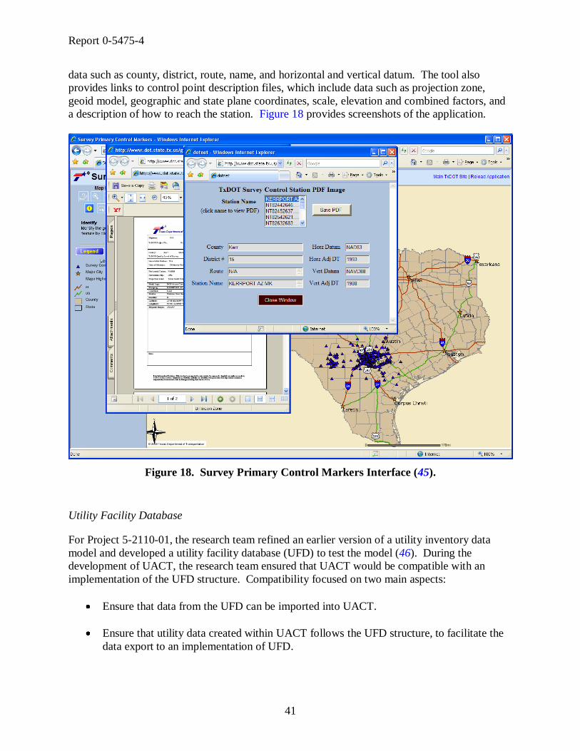
Report 0-5475-4
41
data such as county, district, route, name, and horizontal and vertical datum. The tool also
provides links to control point description files, which include data such as projection zone,
geoid model, geographic and state plane coordinates, scale, elevation and combined factors, and
a description of how to reach the station. Figure 18 provides screenshots of the application.
Figure 18. Survey Primary Control Markers Interface (45).
Utility Facility Database
For Project 5-2110-01, the research team refined an earlier version of a utility inventory data
model and developed a utility facility database (UFD) to test the model (46). During the
development of UACT, the research team ensured that UACT would be compatible with an
implementation of the UFD structure. Compatibility focused on two main aspects:
Ensure that data from the UFD can be imported into UACT.
Ensure that utility data created within UACT follows the UFD structure, to facilitate the
data export to an implementation of UFD.

Report 0-5475-4
42
UACT’s logical data model demonstrates the full compatibility of the system with the data
structure provided by project 5-2110-01 by replicating several of UFD’s utility feature tables.
To ensure the two main aspects of compatibility between UACT and UFD, it was not necessary
to recreate the complete UFD data model in UACT. As a result, UACT does not include all
tables of the UFD structure. As of this writing, no TxDOT district has a working implementation
of a UFD. However, it is likely that a future implementation of UACT could incorporate an
implementation of the UFD data model.
Utility Installation Review System
The Utility Installation Review (UIR) System is a web-based application to support the
management of requests for utility installations on the state right of way (47). UIR is being used
by several districts and TxDOT is expanding the use in a current statewide implementation effort.
UIR uses an implementation of ESRI Arc Internet Map Server (ArcIMS®
) and Oracle DBMS.
UIR and UACT use the same Oracle database system and share several web applications. The
research team designed the UACT data architecture with the intention to share data components
in a UACT implementation to ensure integration of the two systems. Currently, UACT shares
the table structure for user management with UIR to ensure that a future implementation will be
able to link to these tables, which will enable UIR users to use UACT without a need to create a
new user account.

Report 0-5475-4
43
CHAPTER 3. UTILITY COORDINATION ACTIVITIES OF PDP
STAKEHOLDERS
INTRODUCTION
The researchers complemented the information provided by TxDOT’s technical documentation
by discussing utility relocation and coordination activities in the project development process
with TxDOT officials in Austin (both at the district office and SH 130 project office), Dallas,
Houston, and San Antonio. The researchers also met with representatives from utility companies
and consultants to gain an understanding of their perspective about the utility coordination
process.
UTILITY COORDINATION AT TXDOT DISTRICTS
During meetings with TxDOT officials, the researchers discussed the utility coordination
process, utility coordination issues, and current utility tracking and conflict management
strategies. The following summarizes the information and opinions that district officials
provided to the research team.
Utility Coordination at the Austin District
Utility Coordination Process
The Austin District strives to follow the guidelines of the UCMP using a flexible utility
coordination procedure that adapts to the needs of each project. In essence, the district uses the
UCMP by selecting those activities that appear suitable for each particular project. In the
districts’ experience, the UCMP recommends too many meetings for a typical project and, as a
whole, is better tailored toward large-size projects.
To involve utilities early on in the project, the Austin District attempts to send out notifications
to utilities but recognizes that they are not always consistent in this practice. Communication
between TxDOT and utilities is in general good, but could be improved in terms of following up
on issues and sending out reminders and notifications if utilities get behind schedule.
According to district officials, utility coordination is often underestimated in terms of assigned
human and fiscal resources. As a result, there are little labor or financial resources available for
utility inspection, monitoring, and verification. Accordingly, the district strives to prioritize and
optimize utility coordination activities. The district optimizes utility coordination for a particular
project mainly by determining which activities are essential in the coordination process, which in
turn determines when utility coordination activities begin. For example, there are often not
enough resources to conduct utility coordination activities before the start of detailed design. In
those cases, the project’s geometric schematic is already complete when utility coordination
activities begin. Utility coordination activities vary greatly depending on the project type and its
unique dynamic features in terms of activities and processes performed. Some projects are
regular developments; others are fast-tracked projects including toll projects. There are
Report 0-5475-4
44
traditional, design-build, developer-driven, and concessionaire type projects. Depending on the
project, utility coordination may start at different times during the project development process
and may include different sets of activities.
In the Austin District, area offices have been responsible for utility coordination since the 1980s
when TxDOT reassigned utility coordination activities statewide from district offices to area
offices. The majority of utility coordination activities deal with non-reimbursable utilities, which
are much easier to deal with than reimbursable utility adjustments. Non-reimbursable
adjustments require only a Utility Joint Use Acknowledgement (UJUA), Non-Reimbursable
Utility Adjustment (form ROW-U-UJUAB) as compared to the far more extensive Standard
Utility Agreement (form U35) that is a requirement for reimbursable utility adjustments. Austin
District officials reported that in some cases, reimbursable utilities have started adjustments
without signed agreements, which then cannot be reimbursed by TxDOT. From the district’s
experience, it can be a lengthy and time-consuming process to acquire signed utility agreements.
For that reason, area offices preferred using the Date of Eligibility forms (DOEs) that specified
the date after which the utilities activities are eligible for reimbursement without the immediate
requirement to sign a utility agreement. However, the ROW Division intended DOEs for use on
an exceptional basis and in emergency situations only, with the understanding that the utility
would provide a utility agreement at a later time and as soon as feasible. DOEs, however,
quickly evolved as the standard for utility coordination, and in many cases, the Austin District
did not receive a utility agreement subsequently. In July 2005, the ROW Division clarified that
DOEs are intended for emergency use, removed the forms, and replaced them by two new forms
called U# Authorization Work Sheet – Pre-Highway Letting (form ROW-U-AWS), and
Emergency Work Authorization – Post Highway Letting (form ROW-U-EWA). The Austin
District has not used either form very often, and now spends more time to get signed utility
agreements.
The Austin District makes an effort to stop issuing permits for utility installations once a
construction project is in the planning stage. The district does not allow utilities to move in the
right of way of a planned project unless the utility signs a letter of intent that it will move out of
the right of way if necessitated by the planned project. If TxDOT determines utility conflicts
early in a project, the Design Section employees may sometimes adjust their design.
Occasionally, changes in the design appear feasible but the designers are not willing to redesign.
Utility Coordination Issues
The district’s two major utility coordination issues are utilities that cannot adjust in time for
letting, and utilities in conflict with proposed design that are only identified after construction
has started. The Austin District acknowledges that all utilities should be identified, and
preferably adjusted prior to letting. However, the district perceives that the level of detail
required in standard utility agreements is growing steadily, which makes it increasingly difficult
for utilities to prepare them and as a result, increasingly difficult for the district to get signed
agreements in a timely manner. Some utility companies find the agreement process, in particular
the detailed estimate, too complicated, too detailed, and too inflexible. Many utility companies
only do a small share of their work in Texas, which in their view does not justify changing the
way they do business, including providing detailed estimates. Detailed estimates take longer to

Report 0-5475-4
45
prepare and increase the liability for the utility companies since they could be held to their
estimates. Although utilities have the current year plus two years to submit their bills to TxDOT,
it is not enough time for some companies. From the district’s perspective, these companies
create significant problems and are less cooperative with the next utility adjustment. Some of
these issues can be avoided if the district can include the utility adjustment in the highway
contract. This is the Austin District’s option of choice, although it is not always feasible. The
district’s experience is that utilities that are included in the highway contract produce fewer
construction delays.
Utility easements and redesigns can also be a major problem. For example, frequently sidewalks
and bike trails are only afterthoughts that can become a major problem if they are in conflict with
existing utility lines. In other cases, utility installations weave in and out of easements, where a
utility line is located only in part in the TxDOT-managed right of way with other parts in private
easements. This situation makes it more difficult to adjust the utility.
To Austin District officials it appears that utilities are increasingly unwilling to begin design
work on their adjustments until about 90 percent of TxDOT’s design is completed. This may be
a result of negative experiences with TxDOT and the UCMP that utilities had in the past. Such
negative experiences may include projects that TxDOT canceled or where TxDOT determined
that the utility did not need to move, after the utility already completed the design of the
adjustment.
An area of concern to the Austin District is the overlapping of right of way parcels over multiple
construction CSJs. This problem may occur if TxDOT splits up large projects in phases with
different construction CSJs while maintaining one right of way CSJ. Officials mentioned that it
is now a statewide mandate to adjust the right of way CSJ to match the construction CSJ, so this
issue may become obsolete.
To Austin District officials it is unfortunate that a significant amount of utility information is
either lost in the current business process or too difficult to access. For example, the Right of
Way Section does not know what happens to new utility installations after as-builts are provided,
nor does right of way know what happens to the utilities after construction is complete. In
essence, only the Maintenance Section has some of that information. Austin District officials
suggested keeping utility permits in a centralized location where both sections have access.
Current Utility Tracking and Conflict Management
The Austin District has limited internal utility conflict tracking or management capabilities. The
area engineer determines the technologies to gather and track utility information, which may
include spreadsheets and reports created by local public agencies. Some utility coordination
consultants have more advanced utility tracking systems. One consultant uses an electronic data
management system (EDMS) that tracks utility locations using x and y coordinates. A
consultant for the SH 130 project developed its own utility tracking system called ―Utility
Tracker.‖ This consultant provides monthly utility status reports consisting of three parts—(1)
Identification, (2) Assembly and Agreement, and (3) Construction and Payment—for each

Report 0-5475-4
46
project segment of the SH 130 project. The Identification part is a listing with general
information about the utility installation by utility agreement assembly number, including:
line ID, segment, and section;
utility owner;
utility description, size, and material;
baseline station;
enter and exit right of way station and offset; and
existing right of occupancy type (e.g., permit or easement).
The Assembly and Agreement part is a listing that shows agreement information by utility
agreement assembly number, including:
line ID, segment, and section;
proposed action;
responsible party;
estimated adjustment amount; and
several dates (executed by owner; executed by developer; Texas Turnpike Authority
(TTA) approval; Utility Joint Use Acknowledgement executed by owner; Utility Joint
Use Acknowledgement executed by TTA).
The Construction and Payment part is a listing that contains construction progress and payment
information by utility agreement assembly number, including:
line ID, segment, and section;
several dates (scheduled and actual construction start, scheduled and actual construction
completion);
betterment in percent; and
payment info (total payment amount, payment amount, payment type and date, partial
and final payment).
Eligibility ratio and accrued depreciation credit are not tracked by the system. Although the
system has been very beneficial to the district, some officials mentioned that this tracking system
is too complex and requires too much data, and would therefore be too difficult for TxDOT to
maintain. One suggestion was to track utilities using the utility agreement number (U-Number).
For other projects, the district does not have access to the tracking system described above.
Without a similar system in place, and given the current staffing level and coordination demands,
it is not feasible for the office to manually track all utility lines in a project. For these projects,
the district office focuses on what it perceives as the essential task, which is tracking utility
agreements of conflicts associated with reimbursable utilities. To track these agreements, the
district uses a spreadsheet with color codes that distinguish the current agreement assembly
status, such as ―approved‖ (blue) and ―finished‖ (green). The spreadsheet keeps track of several
data items:

Report 0-5475-4
47
U-Number;
number of assemblies;
number of adjustments;
section number;
status (approved, conditionally approved, or other comment) and reason;
dates (returned to consultant, and consultant submittal);
utility adjustment amount; and
comments.
The spreadsheet contains the following sections:
utility assemblies approved,
utility assemblies forthcoming,
TxDOT permits approved,
TxDOT permits on hold/pending,
advanced utility installations approved,
advanced utility installations pending,
rocks in the road,
utility adjustments in progress, and
completed utility adjustments.
Although the district tracks utility agreements of conflicts associated with reimbursable utilities,
the district does not track any data elements of the utility conflicts (e.g., location, type, etc.) or
the utility lines (e.g., location, type, material, etc.) Further, the district does not track any
information about conflicts that are associated with non-reimbursable utilities. The majority of
utility adjustments at the district are non-reimbursable contracts, and the district handles about 50
reimbursable contracts per year. On average, there are about four utility adjustments per utility
agreement. However, a single large project can have 50 utility adjustments and more. In such a
case, the project is broken up into phases, and U-Numbers are usually broken up by construction
phasing.
The Austin District maintains a centralized list of utility industry contacts. However, given the
turnover at utilities, it is not feasible for the district to keep that list current. Further, many
utilities may not have utility adjustment projects for years. Occasionally, TxDOT updates that
list when new projects start and as time permits.
Recommendations for a Future Utility Information Management System
Austin District officials recommended that the researcher keep the new management system as
simple as possible. Utility coordinators are already overcommitted and cannot populate another
complex database. One recommendation was to determine exactly what data is needed and what
data elements should be stored. Austin District officials suggested six essential data elements for
the utility data management system:

Report 0-5475-4
48
U-Number,
relocation cost estimate,
payments and total cost,
parcels,
acquisition schedule, and
automated notifications for critical dates.
They also provided several recommendations to consider in the development of the utility
management system:
Keep data input as simple as possible.
Track project milestones.
Track utilities and parcels in one place.
Handle both reimbursable and non-reimbursable utilities.
Handle both design-build and traditional contracts.
Track utilities at the assembly level (such as from point A to point B) for each company.
Provide mechanism to store and manage access to utility data gathered or generated
throughout the project development process.
Provide a mechanism to exchange a conceptual plan produced early during the
preliminary design meeting or in a separate meeting. Utilities could use the plan to lay
out their lines. This plan should be voluntary and disseminated concurrent to public
meetings. Utilities could be overlaid on a map or a CAD drawing using U-Numbers.
Utility Coordination at the Dallas District Office
Utility Coordination Process
The Right of Way Section typically learns about new projects during annual meetings with each
of the Design Sections and area offices that update what is on the Unified Transportation
Program (UTP) and the Transportation Improvement Plan (TIP), and what the letting schedule is.
Increasingly, the advanced planning group notifies right of way about upcoming projects. The
Dallas District office essentially follows the UCMP as described in the Utility Manual.
Depending on the size of the project, the district may only perform the steps and meetings of the
UCMP that the district determines are important and reasonable.
The primary contact for utility coordination is the area office. Each area engineer is responsible
for the utility coordination in his/her geographical area, and utility coordination practices vary by
area office. The area engineer essentially determines who should conduct inspections and what

Report 0-5475-4
49
projects require inspection. Some area offices use a utility coordinator to do the coordination,
while some use a maintenance inspector. Other area offices perform collection and processing of
information as well as most of the coordination in-house.
Utility coordination includes a number of meetings based on the project size and complexity. At
the annual meeting with utilities, all area offices hand out a project list to utilities. As projects
come up during the year, the area offices send out notifications to utilities. Area offices
coordinate utility relocations, both reimbursable and non-reimbursable. The focus of the effort is
to accommodate utilities if possible, and to design around the utilities. The district office is more
involved in reimbursable contracts, and reviews utility agreements and manages utility billings
and payments. Each area office forwards both reimbursable and non-reimbursable contracts to
the district office in hardcopy for approval. By reviewing both agreements, the Dallas District
Right of Way Section perceives it improves consistency of handling agreements across the
district and avoids miscommunication between the maintenance and Design Sections. For each
utility agreement, the area offices submit four hard copies, one copy each for the district, area
office, division, and utility. The area offices have been using utility permits for non-
reimbursable installations in the past and are now transitioning toward Utility Joint Use
Acknowledgements.
The typical process of adjusting utilities includes the following steps:
Find out what utilities are installed within project limits.
Determine ownership and contacts for utilities involved in the project.
Determine which lines are in conflict and will have to move.
Determine available space for utilities to move.
Examine adjustment constructability and develop timeframe and set of plans.
Determine who has to go where, who has to move first, and who has to go how deep.
In addition, reimbursable adjustments need a right of way release. Non-reimbursable
adjustments typically do not involve the purchase of new right of way; therefore, they do not
need a right of way release. The district office enters all reimbursable contracts into ROWIS.
For non-reimbursables adjustments, the action depends on the form the district uses. Dallas is
steering toward having both types of adjustments in ROWIS. Reimbursable adjustments
sometimes adjust quicker than non-reimbursables but not in all cases.
Use of SUE depends on the project complexity and TxDOT’s confidence in the data provided by
utilities. Typically, a request from an area office initiates a contract with a SUE provider, or if
the district office believes that a SUE contract is warranted for any other reason. The district has
a continuous contract with a SUE provider that it can use for any project. There are no specific
factors that automatically justify SUE. The real limitation to SUE contracts is the amount of
SUE money available to the district, which is not directly related to a project. Because of the

Report 0-5475-4
50
limited funds, the Dallas office prioritizes SUE for projects. Usually, SUE consultants are tasked
to pick up all utilities within the project limits at quality level B. Depending on the project, it
may become necessary to survey at quality level A. Test holes become necessary if a utility is
potentially ―salvageable,‖ meaning the utility may remain in place if TxDOT design can be
modified. If quality level B is not needed, TxDOT can save some money using quality level C.
However, occasionally even SUE does not detect all utilities, such as old materials like clay-tile
pipe or other material that is not easily detectable using regular SUE techniques.
The Dallas District is in the process of implementing a requirement for a type of certification for
as-built documentation to address the low quality of many as-builts. Ideally, the Dallas District
would like to achieve the certification without having to make it mandatory for all types of
projects. The district requires as-builts for some types of utilities, including gas, water, and
sanitary sewer installations. For those types of utilities, the Dallas District usually receives at a
minimum some type of plan that may become an as-built. In contrast, utility coordination
consultants always submit as-builts because they are pay items, but in many cases, the accuracy
of these as-builts has been questionable. In many cases, these as-builts are not tied to TxDOT
controls, and occasionally do not reference the right of way map. Frequently, consultants
provide locations by measurements with respect to the fence line or the edge of pavement, which
are not fixed locations, may change during construction, and therefore are not adequate
references for measurements as compared to the right of way line. Therefore, locations provided
on as-builts may vary from actual locations of utility installations, and TxDOT’s trust in these as-
builts has been generally low. To improve the quality of the as-built documentation provided by
consultants, the district has started to require utility coordination consultants to tie all inspection
measurements and subsequent as-builts to the right of way line. If the right of way line is not
staked out, consultants are required to hire a surveyor to determine the location of the ROW.
The consultant provides MicroStation drawings and/or GPS coordinates of utility installations
along with hard copies to the district office.
The Dallas District has a database of utilities and contacts with over 1000 records. However, the
database is notoriously outdated, since most utilities have active adjustments only once every
few years. By the time a utility in the database has a new active adjustment, the record is usually
outdated: employees have moved on, phone numbers have changed, and even the utility name
might have changed. It would take a serious effort to maintain a current database. Instead, the
Dallas District updates the database whenever a utility calls or when agreements come in. The
Dallas District uses the database contents only as a starting point for utility coordination
activities.
Many projects include some local (e.g., county or city) participation. Local participation ranges
typically from 5 percent to 10 percent of the total project cost. In those cases, the district leaves
it to the local authority to decide who should take the lead on a project, i.e., who should become
the acquiring agency. At the Dallas District, in almost all cases TxDOT becomes the acquiring
agency.
The Dallas District sometimes hires consultants to perform utility coordination functions. The
utility coordination contracts typically include provisions that require the consultant to monitor
the utility installations to ensure that all installations are in according to the approved plans.

Report 0-5475-4
51
There are no set standards to when these contracts should be awarded; they are typically awarded
upon recommendation by the design engineer. Good project candidates are areas that change
from rural to urban (e.g., rural FM road to urban FM road) or highly complex projects. The area
offices like these contracts in particular and typically try to maximize their use. Utility
coordination contracts give the district office considerable flexibility, since the district or area
offices typically do not have the resources to inspect all utility installations.
Utility Coordination Issues
District officials outlined a major difficulty in the utility coordination process, which is the level
of expertise of utility company employees. Problems with utility coordination do not always
arise because of unwillingness to cooperate but often because of lack of competence. Frequently,
utility employees that handle the utility side of the coordination are not qualified, cannot read
design plans, and do not understand basic engineering concepts such as cut and fill, stations, or
offsets. Most utilities are primarily interested in reducing their costs and complain if Dallas
District officials ask them to maintain basic design standards. To some utilities, an adequate
design drawing may consist of only a few lines drawn on paper without any reference
whatsoever. However, more and more utility companies use consultants, who produce drawings
that are more satisfactory.
Another common problem according to district officials is that utilities do not provide reliable
information about the horizontal or vertical location of their facilities. Drawings produced by
utilities provide utility elevations, but frequently these drawings do not differentiate between
existing and proposed elevations. This practice leads to unreliable construction drawings, which
can cause further problems in the field: frequently utilities may relocate on time but to the wrong
elevation. Unreliable references such as the fence line or the edge of pavement frequently cause
utilities to relocate to the wrong horizontal location. In either case, utilities appear to be cleared
and Dallas District officials include these utilities with a cleared status in the utility certification
document. Since these utilities are in fact not cleared they often result in expensive highway
contractor charges because of delays to highway construction that are payable by TxDOT.
Dallas District officials mentioned that based on the documentation they receive, utilities appear
to increasingly cut back on engineering and surveying and leave those activities to a contractor
who only estimates the location of the new line. Those contractors benefit from the fact that
most area office inspectors are usually tied up in construction jobs and very seldom have time to
inspect utility jobs.
In the view of Dallas District officials, there are three common causes of utility adjustment and
project delays:
Utilities are notified late of a project.
Utility conflicts are not identified.
Utilities are non-responsive and uncooperative in providing utility information to the
district or area office.

Report 0-5475-4
52
Dallas District officials pointed out a problem with the standard TxDOT deadline to submit final
utility bills. Some utilities lose track of reimbursable contract payments until the deadline for
submitting bills to TxDOT, which is the current plus two years, has passed. Utilities can then
only file a claim to the state of Texas, which is a lengthy process with an uncertain outcome.
The Dallas District does not send out reminders if the deadline is approaching, but it does let
them know about the current plus two-year timeframe when the utility signs the contract.
Current Utility Tracking and Conflict Management
The effort of tracking utilities at the Dallas District office depends on the type of project.
Typically, the Dallas District office uses spreadsheets and notebooks, and relies primarily on
each area office to coordinate utility adjustments during a project. The district currently has a
system with minimal capability to track status of agreements. The system is a Microsoft Office®
program that the district developed internally and that has no reporting capability.
The Dallas District has been developing a project management system using DCIS data that has
several reporting capabilities. Several offices in the district have access to the system and may
make changes to a certain portion of the data. The system uses the DCIS data because all area
offices enter data into DCIS, and the district wants to avoid multiple data entries and data
inconsistencies. The management system is capable of projecting due dates based on an
estimated timeframe. The system also has fields for estimated dates and timeframes for each
project phase, including environmental clearance, right of way purchases, right of way map,
approved schematics, etc. If the actual time needed to complete a project phase changes from the
initial estimate, the system automatically adjusts all other timeframes and the total time needed
to clear all utilities. The district plans to expand the system to include a utility tracking feature in
a future version.
Recommendations for a Future Utility Information Management System
Dallas District officials recommended that the new system should have several reporting and
tracking capabilities, including the following:
time stamp for the initiation of the coordination process;
time stamp for the submission of agreement to the district office;
time stamp for the submission of agreement to the ROW Division or alternatively, time
stamp for the approval of agreement at the district;
mechanism to track any supplemental agreements;
mechanism to estimate the utility adjustment completion time;
Report 0-5475-4
53
mechanism to estimate total construction time; and
mechanism to show the conflict location.
Utility Coordination at the Houston District Office
Utility Coordination Process
Utility and right of way certification is a vital part of the PS&E documentation that the district
submits to the Design Division. For any given project, it is necessary to track the progress of
utility adjustments because they become part of the utility certification. Utility certifications
verify that all utility adjustments are complete except for those listed on the certification. For
those utilities that have not been adjusted, the certification lists location station, description,
owner, and expected completion (adjustment) date. The utility certification designates expected
completion date by a letter (e.g., A, B, or C), which refers to certain conditions with regard to the
expected adjustment time (60 or 90 days after right of way purchase, 30 days after the
completion of an outstanding adjustment, etc.). The same list of outstanding utility adjustments
may also appear in the PS&E documentation as a ―Special Provision – Important Notice to
Contractors.‖ By comparison, right of way certifications certify that all right of way parcels
have been acquired for a defined project section except for those listed on the certification. The
right of way certification typically lists the anticipated acquisition date for those parcels that have
not been purchased.
Providing and documenting utility certifications is a major task that the district has to complete
in the utility coordination process. Essentially, the certification ensures that the contractor is
aware of the status of all outstanding utility adjustments. By making the contractor aware of
outstanding utility adjustments, it also protects TxDOT to some degree from contractor charges
for suspension delay that occur if the contractor is delayed by utility conflicts that have not been
adjusted at the time the project is awarded.
The utility coordination process at the Houston District office follows essentially all activities
that are outlined in the UCMP. However, due to the volume of projects at the district, Houston
has developed a modified version, which outlines five definitive milestones:
Preliminary Design
30 percent Design
60 percent Design
90 percent Design
Final Design
Depending on the complexity of the project, designers may not require or host all of the meetings
recommended in the UCMP as long as the milestone objectives are met. For the annual meeting,
TxDOT disseminates a list of planned projects to all stakeholders.

Report 0-5475-4
54
Typically, projects begin with a conceptual design that involves schematics and planimetrics
(e.g., aerial imagery). Subsequently, the district determines the location of utilities, the utility’s
owner, and the utility’s responsible contact, which involves a considerable amount of
communications, e-mails, and phone calls. Once all the data are compiled, the district sends the
information on utilities electronically to the utilities. The district has found that it is crucial to
keep the utilities informed while the district leads the utilities through every step of the process;
otherwise, the coordination effort may run into problems.
Further steps are budgeting, programming, and scheduling of public involvement. Next, the
schematics are handed over to the Design Section, which has a certain amount of time to develop
detailed plans and alignments. At this point, the Design Section may request utility information
from utility companies. Some utilities require a formal request on special forms if TxDOT
requests documentation from utilities. The Design Section then makes a decision on whether to
hire a SUE consultant. If the district decides to hire a consultant for SUE or for utility
coordination, it typically occurs after preliminary design. Hiring a SUE consultant later in the
process may provide less benefit and may reveal a utility detail with a profound impact on design,
leading to greater cost in terms of resources and effort. Nevertheless, SUE may be started at any
point along the process. After all utility data have been received by TxDOT, the Design Section
attempts to match the utility data with other available data and identify utility conflicts. If
possible, the district will make an effort to accommodate the facility’s design between 30 percent
and 60 percent design by placing the new road design in the area of least impact. However, most
utilities are only interested at what time the project will be let.
TxDOT can handle utility adjustments as stand-alone adjustments or they can be included in the
highway contract. At the Houston District, water and sanitary sewer utilities are typically
included in a highway contract; others can be included in the highway contract if all involved
parties agree. For example, the district will try to include manholes into the highway contract if
they are encompassed by pavement.
The Houston District uses consultants to provide SUE and utility coordination services. Utility
coordination consultants cover all activities of utility coordination, including utility relocation
inspection and surveying, and provide the district with signed utility agreements and as-built
documentation of adjusted utility facilities.
The approach used to gather utility facility information depends on the complexity of the project
and the amount of pre-existing utility data. For smaller size projects, it may be sufficient to
perform a visual inspection at the project location and record the data in a field notebook. The
use of SUE is at the discretion of the project designer and becomes more likely with increasing
complexity of the project. For new projects, the district typically performs a preliminary, i.e.,
visual utility, inspection to determine if SUE is warranted. The visual inspection is important to
get a good understanding of the utility situation and indicate important visible utility installations.
The visual inspection may result in annotated schematics with approximate utility locations.
District officials estimated that without a preliminary inspection, inexperienced SUE contractors
would only locate about two-thirds of the existing utilities within project limits. The preliminary
fieldwork is also critical to estimate the number of necessary test holes if SUE data at quality
level A are required.

Report 0-5475-4
55
Utility Coordination Issues
There has been a major change in the way the district handles utility agreements. In the past, the
district often used the DOE option. The DOE gave the utility the assurance that from the
specified date forward it could accrue eligible costs for design work in advance of an executed
utility agreement. Although DOEs initially authorized physical adjustment of the utility,
eventually TxDOT removed this authorization from all DOEs. In addition, DOEs did not
guarantee that all costs incurred by the utility were eligible for reimbursement. Over time, DOEs
were used for more projects than they were intended for until the ROW Division replaced DOEs
with Emergency Work Authorizations (EWAs) in July 2005. About half of the Katy Freeway
utility coordination was completed using DOEs. The district uses EWAs very infrequently and
now focuses on signed utility agreements. The utility agreements involve considerably more
paperwork, and getting them signed by the utility is becoming increasingly difficult. As a result,
the Houston District spends a substantial amount of time and resources on getting signed utility
agreements/assemblies. The level of cooperation varies considerably from one utility company
to the next. Occasionally, utilities provide all information necessary for the utility agreement but
then refuse to sign it.
District officials noted that one problem with current conflict lists is that some lists do not
provide information on which side of the roadway the utility conflict is located. Another issue is
the accuracy of plans provided by utilities. Plans rarely contain positional references such as
coordinates. In most cases, plans only show the approximate location that TxDOT then needs to
verify by another process such as SUE. It also happens that utilities provide maps of their
facilities but only include major facilities, such as transmission lines, but not minor facilities,
such as service lines.
Although SUE provides great benefit to utility coordination and detection of utility conflicts,
there are some issues associated with SUE. To assure that SUE data is reliable it is important to
use experienced and dependable SUE contractors that are familiar with the requirements of
standard TxDOT SUE contracts. Some district officials were concerned about the storage of
SUE data after the district receives the data from the consultant. The district collects a wealth of
utility data, but the data are not available to all parties within TxDOT that could use the data,
partly because there is no centralized storage for the SUE data.
There are attendance and response problems with utilities at the 30 percent, 60 percent, and 90
percent meetings. If a utility does not attend a design meeting, it creates an additional burden for
the district to schedule individual meetings with each utility that failed to attend. Although most
utility companies appear for the 60 percent or 90 percent meetings, it is often unsatisfactory to
the district because it is too late in the process to avoid major utility conflicts. If utility conflicts
are detected early in the process, it is sometimes possible to accommodate utilities in the design.
On the other hand, it is somewhat understandable that utilities want to get involved only at a later
stage of the project because TxDOT design may change in the earlier stages, which then forces
the utilities to redesign their facilities.
In the past, some utilities did not submit their final bills within the allowed timeframe. The Code
of Federal Regulations (CFR) Title 23 Part 645 requires utilities to submit a complete billing of
all costs incurred (or agreed lump sum) within one year following completion of the utility
Report 0-5475-4
56
adjustment (48). Federal-aid highway funds may also participate in billings that the state
received at a later time, if the state desires to pay them. Texas state law requires the utility to
provide a final bill of the adjustment within the current plus two years as a result of the biennial
legislative funding appropriations (49). If a utility submits its final bill after the current plus two
years time limit, TxDOT is not authorized to reimburse the utility, and the reimbursement is not
subject to the ―Prompt Payment Act‖ that requires payment for goods and services received by
governmental agencies within 30 days (50). Although utilities can make a request for payment
directly to the state legislature, it is a lengthy and time-consuming process that does not
guarantee that the utility will be reimbursed. This issue has negatively affected the relationships
between TxDOT and the utilities that have not been reimbursed, because these utilities believe
they have been treated unfairly.
Current Utility Tracking and Conflict Management
The Houston District uses spreadsheets to manage utility contact and conflict information.
Spreadsheets for contact information typically contain utilities ordered by installation in either
private or public ROW, a contact name, company name, contact title, address, and phone number.
Spreadsheets to manage utility conflicts typically contain an ID, name of utility company,
contact info, utility type, conflict station and offset, proposed structure that is in conflict,
adjustment date, remarks, and utility relocation needed (yes/no).
The Houston District also has the option to keep track of utility data using the Houston District
Utility Conflict Tracking and Certification Database, which also includes a utility contact
database. Keeping utility contacts current between projects is a difficult task because ownership
of facilities changes frequently, high employee turnover at utility companies, and other changes
such as names change of utility companies. Occasionally, utility ownership of facilities changes
even during the adjustment process. Depending on the project, the district also has access to
other sources of utility contact information. For example, the Katy Freeway project’s general
engineering consultant that has been charged with the utility coordination aspect of the project
developed an online database system called ―ProjectSolve‖ that contains utility contact
information for utilities involved in the project. The consultant also tracks utility conflicts with
utility matrices using Microsoft Excel®.
Recommendations for a Future Utility Information Management System
Officials at the Houston District stressed the importance to have all utilities at the 30 percent
meeting and to investigate strategies that would facilitate the early participation of utilities. One
suggestion was to hand out hard copies of the current state of coordination for each utility at all
intermediate design meetings. The district could print a separate report for each utility owner
showing the specifics of that utility such as conflict description, stationing, etc. Each time a
utility would attend a meeting it would leave the meeting with detailed information. At the early
meetings, TxDOT could share information with utilities in the form of print outs and then request
the utility to review and verify that information. Toward the completion of design and PS&E,
these printouts could become the basis for a type of agreement or commitment with utilities that
have outstanding, non-reimbursable adjustments, with an indication of the time the utility will

Report 0-5475-4
57
adjust the facility. The agreement could consist of a Utility Joint Use Acknowledgement
attached to the printouts that would be signed by the utility. This agreement would then become
part of the utility certification and make utilities liable for the timely adjustment of their facilities.
Currently, the district asks the utilities only for a written communication that they will complete
the adjustment prior to construction. If the utility does not adjust as indicated, the district is
liable for delay charges from the contractor. Researchers could investigate if it would be feasible
to include all utilities (in conflict and adjusted, in conflict and not adjusted, and not in conflict) in
the utility certification.
The new system should be designed to keep all engineers and technicians up-to-date. It should
record all transactions, such as adding, change, or exchange of information and the username of
the party responsible for that transaction. The system should also be capable of distributing
meeting reminders and other notifications to system users. These events should become part of
the utility status (e.g., 30 percent meeting notified, 30 percent meeting attended, etc.). The
researchers should investigate how it would be possible to record and track easement interests in
the system to indicate that there is a reimbursable interest.
The utility management system should also be capable of tracking commitment letters from
utilities at the 30 percent meetings if such commitment letters would be implemented in the
future. The system should also be able to generate reports that show utility and conflict locations
that could become part of the commitment letters. The prototype developed by this research
should also contain a feature that would automatically send out reminders to utilities about
upcoming meetings, design changes, and deadlines for billings.
The Houston District has a defined format for utility coordination meetings including meeting
agenda, standard topics, and protocol. The researchers should investigate what other criteria
could be useful to improve utility coordination.
Utility Coordination at the San Antonio District Office
Utility Coordination Process
The San Antonio District Right of Way Section handles reimbursable agreements and joint
bidding, i.e., utility projects included in the highway contract. Non-reimbursable agreements are
handled by the Maintenance Section through the utility permitting process and UIR. The district
then forwards the agreements to the division, which enters the information into ROWIS and
assigns a U-Number. For utility adjustments, the San Antonio District follows a 10-step process:
Right of Way Release and UCSJ Request (Design, Right of Way, and ROW Division)
Alternate Procedure (Design, Right of Way, and utility)
Determine Conflicts/Develop Utility Plans (Design, Right of Way, and utility)
Agreement Assembly (Right of Way and utility)
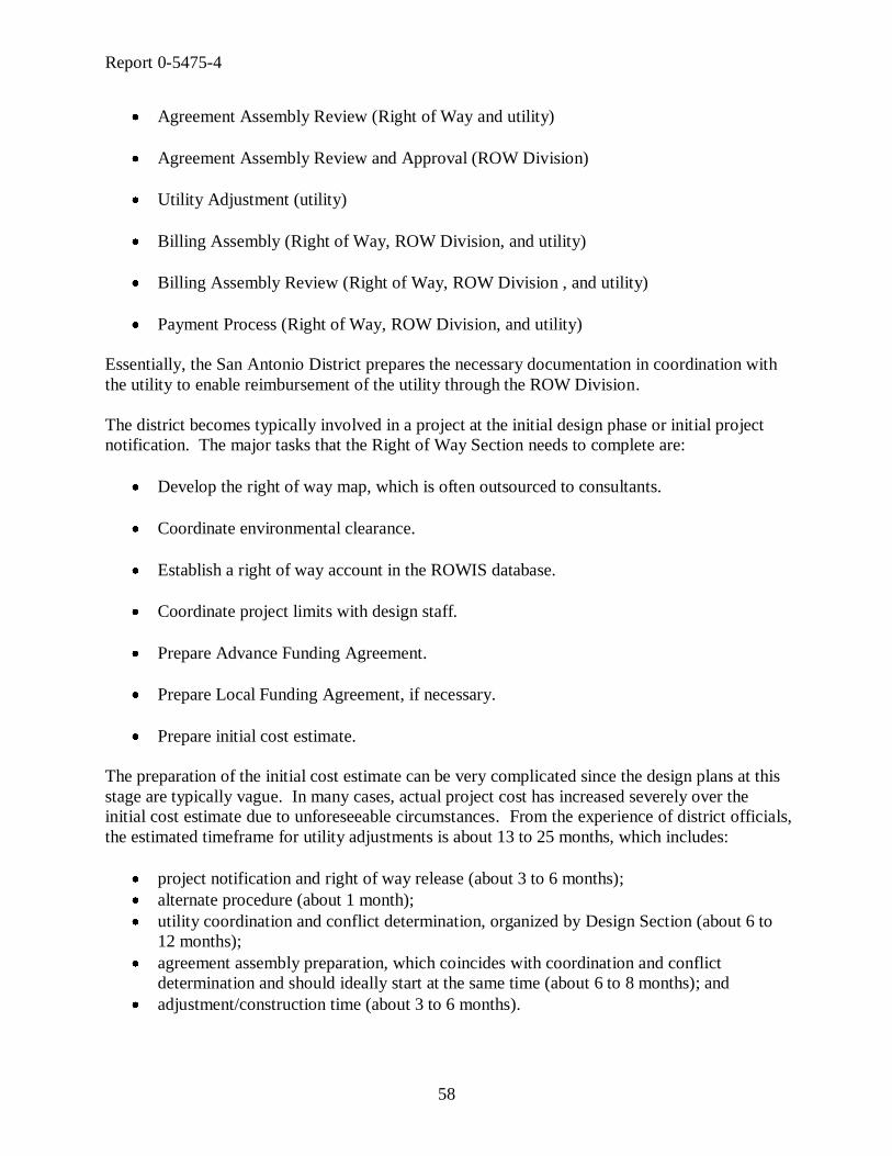
Report 0-5475-4
58
Agreement Assembly Review (Right of Way and utility)
Agreement Assembly Review and Approval (ROW Division)
Utility Adjustment (utility)
Billing Assembly (Right of Way, ROW Division, and utility)
Billing Assembly Review (Right of Way, ROW Division , and utility)
Payment Process (Right of Way, ROW Division, and utility)
Essentially, the San Antonio District prepares the necessary documentation in coordination with
the utility to enable reimbursement of the utility through the ROW Division.
The district becomes typically involved in a project at the initial design phase or initial project
notification. The major tasks that the Right of Way Section needs to complete are:
Develop the right of way map, which is often outsourced to consultants.
Coordinate environmental clearance.
Establish a right of way account in the ROWIS database.
Coordinate project limits with design staff.
Prepare Advance Funding Agreement.
Prepare Local Funding Agreement, if necessary.
Prepare initial cost estimate.
The preparation of the initial cost estimate can be very complicated since the design plans at this
stage are typically vague. In many cases, actual project cost has increased severely over the
initial cost estimate due to unforeseeable circumstances. From the experience of district officials,
the estimated timeframe for utility adjustments is about 13 to 25 months, which includes:
project notification and right of way release (about 3 to 6 months);
alternate procedure (about 1 month);
utility coordination and conflict determination, organized by Design Section (about 6 to
12 months);
agreement assembly preparation, which coincides with coordination and conflict
determination and should ideally start at the same time (about 6 to 8 months); and
adjustment/construction time (about 3 to 6 months).

Report 0-5475-4
59
If the agreement assembly preparation occurs consecutively to utility coordination and conflict
determination, the adjustment timeframe increases to about 19 to 33 months. After construction
is complete, the billing process takes usually an additional 6 to 8 months.
Consultants typically become involved in the development of the right of way map at the start of
a project. To develop the map, consultants need information on project limits and parcels, the
existing right of way map, and information on existing utilities. District officials are usually
satisfied if existing utilities are verified at a SUE quality level C. It is more important to know
about existing utilities in general terms, what company is in the way and where they are
approximately located, than knowledge of the exact location. More recently, the San Antonio
District has started to use consultants to help with utility coordination. Contracts with
consultants vary and may cover one or more of steps 3 through 7 (utility conflicts to utility
adjustment) mentioned earlier. The district does not want these contracts to be involved in the
preparation of the billing assembly package to avoid possible conflicts of interest. There are four
types of utility coordination contracts:
SUE category (contracts include the ASCE 38-02 standard);
utility engineering;
utility coordination; and
utility verification (i.e., inspection).
Utility Coordination Issues
Occasionally, an issue at the San Antonio District has been utilities that do not submit their bills
before the Texas state law mandated deadline. The current deadline, as mentioned earlier, is two
years plus the current year after the completion of construction, which is a result of the biennial
funding appropriations of the Texas Legislative Budget Board (49). If the billing is not
submitted before the deadline, TxDOT cannot reimburse the utility for the adjustment, and the
reimbursement is not subject to the ―Prompt Payment Act‖ for governmental entities (50).
A further issue at the district that has surfaced in the past is a problem with construction and right
of way CSJs. In the past, right of way CSJ and construction CSJ did not always align or have the
same stationing, which was a source of confusion among TxDOT staff and utilities. Recently,
the San Antonio District implemented a new use of right of way and construction CSJ numbers,
mandated by the ROW Division. The district now uses one right of way CSJ for each
construction CSJ number (Figure 19). According to the district, the change to one right of way
CSJ for each construction CSJ has been well received by auditors, utilities, and TxDOT staff.
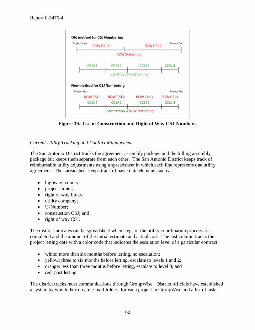
Report 0-5475-4
60
Figure 19. Use of Construction and Right of Way CSJ Numbers.
Current Utility Tracking and Conflict Management
The San Antonio District tracks the agreement assembly package and the billing assembly
package but keeps them separate from each other. The San Antonio District keeps track of
reimbursable utility adjustments using a spreadsheet in which each line represents one utility
agreement. The spreadsheet keeps track of basic data elements such as:
highway, county;
project limits;
right of way limits;
utility company;
U-Number;
construction CSJ; and
right of way CSJ.
The district indicates on the spreadsheet when steps of the utility coordination process are
completed and the amount of the initial estimate and actual cost. The last column tracks the
project letting date with a color code that indicates the escalation level of a particular contract:
white: more than six months before letting, no escalation;
yellow: three to six months before letting, escalate to levels 1 and 2;
orange: less than three months before letting, escalate to level 3; and
red: post letting.
The district tracks most communications through GroupWise. District officials have established
a system by which they create e-mail folders for each project in GroupWise and a list of tasks

Report 0-5475-4
61
with estimated completion dates. By typing that information into each task, they keep track of
phone calls, meetings, and e-mails to create a paper trail.
Recommendations for a Future Utility Information Management System
The Right of Way Section would like notifications about new projects as early as possible.
Occasionally, the Right of Way Section hears about projects for the first time when design is
already at the 60 - 90 percent design stage. At that point, it is usually impossible to adhere to the
letting schedule, and project delays are unavoidable. Similarly, the environmental section
occasionally is not notified of a new project. Ideally, the Right of Way Section would like to
receive notifications every time a new project is entered into DCIS, which would ensure that it is
aware of projects that may involve utility adjustments.
The Right of Way Section would prefer if the district would use only one permit for non-
reimbursable utility installations. That could be the Utility Joint Use Acknowledgement and
would require a change in the UIR system. Right of way personnel could get involved in the
process, but they would rather have the Maintenance Section forward the agreement directly to
the division, maybe using the existing UIR system. Signatures are an important part of the
process at this point. If involvement by the Right of Way Section is necessary, it would need one
set of plans, either paper or electronic copies through access to UIR.
In a new utility conflict management system, the district would prefer to have a feature to
automatically notify the utility by e-mail if the billing is not completed before the deadline. The
system should also be able to handle toll roads and new agreements such as CDAs.
Public utility companies and utility consultants are partners of TxDOT in the UCMP. Although
utility companies have many common business elements, e.g., provide a utility commodity to the
public consumer, there is great variation among utilities in terms of company size, area of
operations, resources available for relocation, familiarity with the UAR, and knowledge about
TxDOT engineering and surveying standards. Although statewide operating utilities may
frequently become involved with the UCMP, many smaller utilities are less often exposed to
utility relocations and the UCMP. As a result, it is not surprising that especially small utilities
are frequently not familiar with TxDOT’s rules, requirements, and procedures. That does not
mean, however, that smaller companies are cause for more delay in the project development
process. In fact, in the view of several district officials, smaller utilities are usually more active
in the earlier stages of the process, whereas larger utilities tend to prefer waiting until the later
stages of the design phase when TxDOT’s redesigns become less likely.
UTILITY OWNERS AND CONSULTANTS
Given the great number of utility companies that all have different business processes it is an
unfeasible task to develop a detailed business process model that includes the business activities
of all utility companies involved in utility adjustments. Nevertheless, it is critical to understand
the perspective of utility companies and their consultants on the utility relocation process to
ensure that the prototype utility data exchange system meets their needs. To understand the
perspective of utility companies, the research team developed a survey focusing on utility

Report 0-5475-4
62
involvement in the project development process, utility agreements, as-built plans, utility
location and conflict data, and several other items regarding exchange of information during the
utility relocation process. A copy of the utility survey is provided in Appendix A. The TxDOT
Houston District provided a list of utility contacts that the researchers used to conduct the survey.
The team conducted the surveys over the phone or through e-mail.
Utility Survey
The utilities contacted for this survey came from a master list of utilities and utility consultants
of the ongoing Katy Freeway project on IH 10 west of Houston. In total, the researchers
contacted eight utility companies and three utility consultants. Four of the utility companies and
one utility consultant completed the survey.
Utility Companies Contacted
AT&T
CenterPoint Energy Houston Electric
TelCove
Broadwing Communications
Genesis Pipeline Texas L.P.
Kinder Morgan Natural Gas Pipeline
Optel TV Max Telecommunications
Phonoscope LTD
Utility Consultants Contacted
Cobb Fendley & Associates
Binkley & Barfield Inc.
Halff Associates
The focus of the survey was to obtain information about the activities, information exchange, and
data needs of utilities during the UCMP. The researchers then used the information to develop a
business process model of UCMP activities from the utilities’ perspective. Given the variation in
business practices of utility companies mentioned earlier, the survey was designed to provide the
researchers with a general understanding of the utility and utility consultant business processes to
supplement the PDP/UCMP business process model.
Utility Coordination Business Process Model
From the responses received by utility companies and utility consultants, the researchers
developed a business process model that combined the companies’ activity descriptions into one
model. This business process model covers the complete timeframe in which utilities interact
with TxDOT, which is from the time of notification by TxDOT through resolution of the
conflict. The following paragraphs describe the business process model in more detail.

Report 0-5475-4
63
Utility Notification
Utility companies receive notification from TxDOT of a utility conflict or possible utility
conflict. Some utility companies receive a letter notifying them of utilities in conflict while
others receive notice to identify conflicts, depending on the preliminary utility research
performed by TxDOT. After receiving the notification, which is usually a letter or e-mail, the
utility company must make a decision on whether to perform utility conflict relocation with
company forces or use a consultant. Company size and complexity of the project are influencing
factors of this decision.
Use of Consultants
If the company decides to use a consultant, the utility company will send all available installation
and as-built drawings to the consultant. Utility installation records can be scaled as-built
information or simple, unscaled schematics, and occasionally there are no drawings available at
all. The utility company or the consultant then requests and receives proposed design drawings
from TxDOT.
The engineering consultant uses both the utility drawings and TxDOT design drawings to
identify utility conflicts. The utility or consultant then ―redlines‖ TxDOT design drawings,
which places red lines of utility locations on TxDOT drawings. According to utility
representatives, the level of accuracy for the redlining should be approximately equivalent to a
level C or D SUE procedure. If the utility company’s drawings are not to scale, a SUE provider
locates the utilities in the field using a level B SUE procedure that involves geophysical
measurements, which some utility companies also refer to as ―designating‖ or ―tone-locating.‖
If the utility company decides to complete the work with its own forces, it also requests a set of
design drawings from TxDOT. The utility company then uses the design drawings to locate
utilities in conflict and presents the results to TxDOT.
Utility Coordination Meeting
To avoid some or all of a utility’s conflicts, TxDOT may consider a design change after
reviewing a utility’s conflict locations. The possibility to redesign depends greatly on the type of
infrastructure that TxDOT is constructing and the timing of the request. At the 30 percent design
state, design changes can be fairly easily accommodated compared to the 90 percent design state
after which there is very little chance for a redesign. There are different strategies to avoid or
remove conflicts. For example, wastewater lines can sometimes be moved vertically or
horizontally to avoid a conflict. However, usually any large structure such as bridge pile and the
roadway itself requires utility relocation and will rarely be redesigned. For reimbursable
utilities, most of these decisions are based on cost, e.g., in most cases the utility lines are moved
because it is cheaper than adjusting the roadway alignment. If TxDOT is able to accommodate
the utility with a design change, the utility provides location information to TxDOT. If TxDOT
cannot change the design, the utility must relocate.

Report 0-5475-4
64
Utility Conflict Resolution
If TxDOT is able to change the design to accommodate the utility, the utility or consultant
provides the utility location to TxDOT for its records. If utilities use a consultant, a SUE
provider will expose the utility with a test hole and tie the location to a TxDOT control point,
which is a level A SUE procedure. If the utility does not hire a consultant, the utility typically
will provide maps or existing utility drawings to document the location of the facility. In
general, researchers found that utility companies who complete their own relocation work are
reluctant to share survey data with TxDOT.
A relocation that involves reimbursement to the utility requires that the consultant or utility
company complete a utility agreement. A utility agreement requires design drawings, cost
estimate, schedule of work, and other documentation. Larger utility companies typically hire
engineering consultants to prepare most or all of the required documentation. In other cases, the
utility company prefers to prepare the documentation for TxDOT. Some larger companies
actually have staff that deal only with utility agreements. A relocation that does not involve
reimbursement to the utility only requires a set of relocation design drawings and a Utility Joint
Use Acknowledgement. Either the consultant or the utility company can complete the agreement.
The utility company submits the Utility Joint Use Acknowledgement either electronically or by
hardcopy to TxDOT. A utility agreement is not required for non-reimbursable work. Once the
design for the utility relocation is complete, and TxDOT and the utility sign the utility
agreement, the relocation effort can proceed. To complete the utility relocation, utility
companies use either in-house crews or bid out a contract.
Observations and Trends
Utility Conflict Notification to Utility Companies
TxDOT notifies utility companies by letter about upcoming projects. The researchers noted that
those smaller utility companies typically receive a notice of conflict while larger companies
receive a notice to identify conflicts. There was no clear indication for this trend, except that
TxDOT may acknowledge that smaller utilities do not have the resources available to perform a
utility survey. Similarly, larger companies appeared to be more likely to hire a consultant to
complete SUE and identify conflicts.
Utility Consultants
Once TxDOT informs the utility company of future construction, the utility company must
decide whether to hire a utility coordination consultant. Reasons for hiring a consultant revolved
around the size and complexity of the project. From the survey, smaller companies appeared to
prefer using their own forces to complete the work. Larger utility companies reported using
consultants frequently for non-reimbursable projects, and virtually for all reimbursable projects.
Utilities may use consultants to locate existing facilities, prepare utility agreements, and relocate
facilities, but some utilities hire consultants for only one or two of these activities. Some utility
companies prefer that the consultants attend the meetings in place of the utility representatives;

Report 0-5475-4
65
some prefer that both utility representative and consultant attend the meetings, and some prefer
that consultant companies do not attend the meetings.
Aerial Utilities
Relocation of aerial utilities varies greatly from relocation of underground utilities. Multiple
utility companies with aerial utilities often share utility poles that are owned by only one of the
utility companies and leased by the others. If the poles need to relocate, utility companies that
are attached to the poles must follow a hierarchy when relocating their facilities. Typically, the
utility companies owning the poles install the new poles and move the lines that they own, and
then companies with leasing rights attach their lines to these poles. The common order to re-
attach utility lines is in the original order utility companies attached to the old poles, which is
usually starting from the top and moving down. The utility attached at the bottom of the pole
cannot move until all other utilities move their lines. If a utility attached higher on the poles
requires a long time to move, it can cause issues among the utilities further down that are waiting
to relocate. It also happens that a utility line that is attached above another line may be no longer
in service or its ownership may be unresolved. Even in these cases, the protocol still requires
that utility companies attached below a line must resolve any lines attached above them.
Early Involvement in the UCMP
A frequent comment from utility companies was that any work done before the 60 percent
meeting could be a waste since TxDOT’s design could still change. Several companies gave
examples of projects where earlier involvement of the utility resulted in a wasted effort on behalf
of the utility. One suggestion from a utility to encourage earlier involvement was to establish a
policy of benchmark drawings that TxDOT would disseminate to utility companies, for example
at the 30 percent design stage. The benchmark drawings would establish eligibility for
reimbursement such that all work after the benchmark would be eligible for reimbursement, even
if the TxDOT design would change and require additional design or construction.
Coordination of New Utility Location
Coordination with utilities to determine the location of their relocated facilities in the right of
way is critical to avoid conflicts among relocated utilities. The location information of the new
utility consists, in the majority of cases, of a measured offset from the right of way line and a
depth below the new grade. Utility companies reported three approaches to determine a utility is
offset from the right of way line:
TxDOT determines and provides the suitable relocation offset location.
TxDOT coordinates with the utility and agrees on a suitable relocation offset.
TxDOT receives and agrees to a request from a utility for a certain relocation offset.

Report 0-5475-4
66
Utility Facility Tracking
Not all utility companies have a good understanding about the facilities they own, and not all
utilities have methods to track them. For those utilities that do track their facilities, researchers
observed a widespread use of spreadsheets as a way to track facilities. Other methods utilities
mentioned were customized, stand-alone, and frequently proprietary applications and procedures.
One utility gave the researchers detailed insight into its utility conflict tracking system. The
utility uses a color-coordinated mapping system and a 4-foot by 8-foot map that shows the
company’s utility routes throughout Houston and its vicinity. If the project manager receives a
notification about future construction from TxDOT, he marks the location on the map. The
utility uses a color code to distinguish types of utility facilities and conflicts:
reimbursable facilities,
non-reimbursable facilities with a conflict,
reimbursable and non-reimbursable facilities with a conflict that will be paid mostly at
the expense of another party, and
reimbursable and non-reimbursable facilities with currently no conflict.
The utility also marks ―caution areas‖ on the map that signify locations of known potential future
routes.
Utility Coordination Issues
Most companies claim to have a good understanding of the TxDOT utility relocation process,
although they may not have heard of the term ―utility cooperative management process.‖
However, there are a few issues that utilities brought up during the surveys. For example, one
utility company felt that TxDOT does not inform its contractors that utilities are not in physical
conflict. Sometimes lines are not in physical conflict but perhaps a construction conflict, and
contractors call utility companies asking them to move or relocate the line. Smaller utility
companies mentioned issues with payments on reimbursable projects. Some utilities have an
impression that TxDOT takes too much time to reimburse utilities and does not have backup
personnel to process payments. If a TxDOT employee handling payments goes on vacation, the
reimbursable payment process is significantly delayed.
A recurring utility complaint was that TxDOT wants to adjust utilities too quickly and/or sets
construction dates before any construction can begin. Some utilities complained that often there
are many design changes, and frequently these changes occur at a late stage in the design
process. A further complaint was that utilities are subject to increased cost and effort if TxDOT
cannot acquire necessary right of way on time, and the utility must move its lines, portions at a
time.
Recommendations for a Utility Data Exchange System
All surveyed utility companies welcomed the idea of an online system to manage utility data and
offered recommendations for such a system. The critical element of such a system that utilities

Report 0-5475-4
67
mentioned most frequently was the accuracy of the data. Utilities repeatedly pointed out that
errors in the available data are a common cause for delays in construction. One company
illustrated this point by giving an example of a competitor that started a utility relocation based
on an incorrect set of design drawings. Although the contractor caught and corrected the mistake
in the field, it cost the utility time and money.
Consultants frequently suggested providing online access to topographic data to transpose utility
locations from records onto TxDOT plans. Consultants would also like the system to provide
information on test holes that other companies completed as well as data depicting elevation, size,
and type of all located facilities. A smaller company requested access to contact information of
other utilities in order to coordinate the attachment of its lines to leased utility poles owned by
other utilities. Many consultants and utility companies recommended that coordination would
improve if they knew the status of other utilities involved in the relocation process. To
encourage early utility involvement, one utility company suggested making participation in
utility coordination meetings a requirement and including in the utility agreement that utilities
must be aware of other utilities around them.


Report 0-5475-4
69
CHAPTER 4. DEVELOPMENT OF TXDOT UTILITY RELOCATION
BUSINESS PROCESS MODEL
INTRODUCTION
The TxDOT Data Architecture Manual describes the integrated methods for the data design
process of a data architecture (51). According to the manual, a data architecture is ―the manner
in which data components are organized and integrated‖ (51). The manual outlines a data design
process that begins with broad user requirements resulting from real-world objects and ends with
detailed technical requirements for database design. This data design process includes the
following six components:
Project glossary. The project glossary includes definitions of terms to facilitate
communication exchange and avoid confusion during implementation of the project. A
project glossary is recommended but not mandatory.
Conceptual data model. A conceptual data model identifies data from a business point
of view. It defines entities (e.g., persons, places, things, concepts, and events) about
which it is necessary to keep data and identifies high-level associations among those
entities. This type of model is recommended but not mandatory.
Logical data model. A logical data model represents the data/information needs
associated with entities and the relationships among those entities. A logical model is a
database-independent model. This type of model is mandatory.
Physical data model. A physical data model represents the mapping of a logical data
model to a database platform (e.g., Oracle, Microsoft SQL Server, or Sybase®). It
translates entities, attributes, and relationships into tables, fields, and constraints. This
type of model is mandatory.
Data dictionary. A data dictionary is a compilation of entity and attribute definitions
(for logical data models) or table and field definitions (for physical data models).
TxDOT system interface diagram (TSID). A TSID is a diagram that documents the
relationships between computer applications and data. The Technology Services
Division at TxDOT (TSD) creates and maintains TSIDs.
This chapter describes the activities of the research team to develop a business process model to
create a graphical representation of business processes that describe the activities of right of way
coordination focused on utilities in the PDP and their interdependencies. Following the Data
Architecture Manual’s recommendation to provide a conceptual data model, the business process
model identifies entities and entity associations and in addition provides a detailed overview of
process activities and the responsibilities, precedence and/or concurrence, and inputs/outputs of
these activities. The development of logical and physical data models in addition to the data
dictionary are described in detail in Chapter 5.

Report 0-5475-4
70
BUSINESS PROCESS MODEL DEVELOPMENT
Sources of Information
To develop a business process model of utility coordination activities in the project development
process, the research team had access to two main sources of information: TxDOT manuals and
TxDOT officials. As a starting point, the researchers reviewed the PDP Manual with a focus on
utility and right of way activities. The researchers found that in many cases, the PDP Manual
lists activities that a project may entail but includes only limited information on how these
activities relate to each other, when they should occur, and for what types of projects they apply.
There is also little information on how TxDOT entities should interact and at what times. In
addition, there are several other manuals (Utility Manual [10], Survey Manual [35], Right of
Way Manual [17], etc.) that describe activities in more detail but occasionally provide
inconsistent information. As a result, a major task of the business process model development
was to reconcile information from several manuals into a single business process model.
Depending on the type and size of a project, there can be an extreme range of required activities
to develop a project from concept to completion. Due to the variation in complexity, TxDOT
rarely documents business processes at a detailed level. The range of requirements also makes it
a tremendous challenge to produce a manual that covers all possible scenarios that projects may
encounter in the project development process. Consequently, the style of the PDP Manual is
such that it leaves much of the process open to the judgment of the project manager. In general,
this approach is not bad considering the alternative would be volumes of process descriptions
that would require enormous resources to maintain and keep current. However, due to the open
style of the PDP Manual, it is not surprising that there are differences in the way districts
interpret activities described in the PDP Manual. The unifying authority in this process is the
ROW Division, which communicates minimum standards and requirements to the districts, and
provides guidance on required activities.
From the start of the model development, it was clear to the researchers that much of the detailed
process information could not be found in manuals but would reside with the TxDOT
professionals that perform the activities on a daily basis. This information is unfortunately for
the most part undocumented, and gathering this information requires numerous meetings and
discussions with process stakeholders. What complicates the development of the business
process model is that information is distributed among a large group of individuals. In addition,
the researchers found that most professionals have either a modest understanding of a large
portion of the process, or an excellent understanding of a very small portion of the process.
Finally, there may be different options available to achieve the same goal and different opinions
on which alternative would be most beneficial. As a consequence, another major task in the
business process model development was to reconcile opinions and interpretations of all
stakeholders.
Integrated Computer-Aided Manufacturing Definition Language Notation
TSD did not require the use of a specific software or modeling language to develop the business
process model, but did require using ERwin, at the time the standard data modeling tool at

Report 0-5475-4
71
TxDOT, for the development of the logical and physical data models. Because of the
requirement for the data models, the researchers developed the first business process model using
Computer Associates AllFusion Process Modeler, which is a companion to ERwin and provides
some integration during the conversion of the business process model to the logical data model.
Process Modeler uses the Integrated Computer-Aided Manufacturing (ICAM) Definition
Language (IDEF), specifically the Integration Definition for Function Modeling (IDEF0) for
business process models and the Integration Definition for Process Description Capture Method
(IDEF3) for process flow models. IDEF0 is a technique that models systems as a set of
interrelated activities or functions for a specific purpose and from a selected viewpoint, also
called a ―function model‖ (52). In IDEF0 diagrams, boxes represent functions, and arrows
represent either inputs, controls, outputs, mechanisms, or calls, depending on their position
relative to the function box (Figure 20).
Figure 20. Function Box and Data/Objects Arrows.
IDEF0 consists of a top-level context diagram, which is a function that is represented by a single
box. For example, Figure 21 shows the top-level context diagram for ―Develop Project.‖
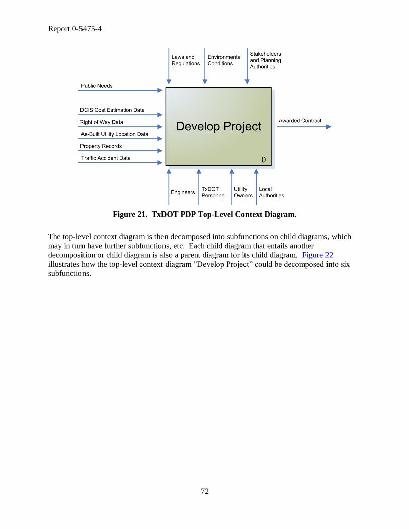
Report 0-5475-4
72
Figure 21. TxDOT PDP Top-Level Context Diagram.
The top-level context diagram is then decomposed into subfunctions on child diagrams, which
may in turn have further subfunctions, etc. Each child diagram that entails another
decomposition or child diagram is also a parent diagram for its child diagram. Figure 22
illustrates how the top-level context diagram ―Develop Project‖ could be decomposed into six
subfunctions.

Report 0-5475-4
73
Figure 22. TxDOT PDP Decomposition Child Diagram.
By comparison, IDEF3 is a technique to capture, manage, and display process-centered
knowledge in a form of scenarios that are displayed as process schematics (53). IDEF3 can be
used to describe a process as an ordered sequence of events along with objects that participate in
those events. AllFusion Process Modeler uses IDEF3 to support IDEF0 models when more
detail and conditional information is available that can be expressed in junctions between
activities, such as ―all following processes must start/end,‖ ―one or more following processes
must start/end,‖ or if the user wants to analyze different scenarios of the same process.
A characteristic of the IDEF business process modeling notation is that all diagrams fit on letter-
sized sheets. Although this format makes it very easy to physically handle and reproduce the
model, the researchers quickly realized that the notation is very technical and less useful to
discuss business process model details with practitioners that are unfamiliar with the notation.
For example, the researchers developed a preliminary business process model of the project
development process in IDEF0 format that consisted of about 70 letter-size pages. Researchers
noted that many practitioners became quickly lost in the hierarchical structure of parent and child
diagrams and were unable to provide useful feedback on the model. A part of the problem is that
model reviewers see only a small portion of the model at a time, which makes it difficult to
picture the whole network, verify existing relationships, or draw new relationships. The
researchers also found that the integration between AllFusion Process Modeler and AllFusion
ERwin Data Modeler provided little benefit to the development of the data models.
Report 0-5475-4
74
Business Process Modeling Notation
As a result of the difficulties with the IDEF notation, the researchers evaluated other options for
business process modeling. One of the options under consideration was the Business Process
Modeling Notation (BPMN), which depicts the end-to-end flow of a business process and has a
process-oriented approach to application modeling (54). BPMN provides three basic types of
models, which are private (internal), abstract (public), and collaboration (global) business
process models. The collaboration business process model depicts interactions between two or
more business entities as sequence of events, activities, and gateways that are arranged in
―pools‖ and ―swimlanes‖ along with data objects. After several experiments, the research team
found that practitioners intuitively understood the BPMN’s collaboration business process model
and were able to provide useful feedback to researchers. Figure 23 shows a collaboration
business process model in BPMN using the example of the utility agreement approval process.
Figure 23. Example of Collaboration Business Process Model Using BPMN.
Collaboration business process models are also called ―swimlane‖ diagrams, because they
associate ownership of or responsibility for an activity with an entity that is represented by the
swimlane. In other words, a swimlane diagram displays activities sorted by the entities, such as
offices or sections within an organization that perform the activities. These entities, sometimes
referred to as roles, have an assigned horizontal space across the length of the model for
activities that these entities perform. As a result, the model takes on a different shape as
compared to the ―standard‖ business process model that simply arranges activities by precedence
to display a chain of events. Because of the activity sorting, swimlane diagrams tend to stretch
horizontally, which may create the impression of a more complex model. However, the
swimlane diagram is simply a different view of a standard business process model. The
advantage of a swimlane diagram is that activities are sorted into the horizontal swimlane of the

Report 0-5475-4
75
entity that performs the activity, and it becomes immediately evident when and how a certain
entity becomes involved in the process.
Business Process Model Development Using BPMN
The research team used Microsoft Visio to produce the BPMN business process models, which
allowed them to show the whole business process model on one sheet of paper. This strategy
proved to be beneficial during meetings with TxDOT officials because they were able to see the
whole process at once and draw lines and link activities from one area of the model to another.
Once the researchers determined the appropriate notation for the business process model, the
next step was to determine the focus of the model or diagram point of view. This step is critical
because the business process model includes several participants, and each participant may view
the diagram in a different way, specifically, how the process applies to them. BPMN does not
currently specify any graphical mechanisms to highlight the point of view, so the research team
included this information along with further limitations and clarifications in the following
disclaimer text that is shown on the main business process model:
―This business process model describes the TxDOT Utility Coordination Process between TxDOT and
other involved entities, such as utility companies, contractors, and consultants. The Utility Coordination
Process is a set of activities that is part of the larger TxDOT Project Development Process. The activities
of the utility coordination process are arranged in swimlanes that represent groups or organizational units
that are involved in the utility coordination process. Each process activity is located in the swimlane of the
organizational unit that has the responsibility to complete that activity. Activities are connected by arrows
that signify precedence. As such, a preceding activity must be completed before the following activity can
begin, or an output from a preceding activity is required as an input by a following activity. The process
model is based on TxDOT’s standard model of project delivery, design-bid-build (DBB). Alternate
methods of project delivery such as comprehensive development agreements (CDAs) and facility
concession agreements (FCAs) may exhibit significant differences from this process model. This business process model was developed using information from the TxDOT Utility Cooperative Management Process
(UCMP) outlined in the TxDOT Utility Manual, the TxDOT Project Development Process (PDP) Manual,
and feedback from TxDOT officials, utility company officials, and utility consultants.
Texas Transportation Institute, 2008.‖
A major challenge in the development of the business process model was to define the model’s
appropriate level of detail. The researchers found that there was an optimum level of
information that provided enough context for a productive discussion with practitioners without
overburdening the participants with too much detailed information. This level of detail was
roughly at the PDP task level, as described in Chapter 2. Although the researchers attempted to
maintain a uniform level of detail throughout the model, it proved beneficial to increase the level
of detail slightly in some areas by including some of the subtasks described in the PDP manual.
The researchers began the business process model development by translating a majority of the
approximately 200 tasks in the PDP Manual into an extensive business process model. To
determine activity sequence, relationships, and dependencies, the researchers reviewed the task
and subtask descriptions of all tasks. Unfortunately, the PDP Manual does not provide a wealth
of information on task sequence, and statements such as ―tasks are provided in approximately
chronological order‖ are typical. Due to this lack of information on activity sequence,
Report 0-5475-4
76
relationships, and dependencies, the model in its first version displayed long chains of activities
with little concurrency and few links between different TxDOT groups. Clearly, this first
version was not an accurate reflection of the actual TxDOT project development process, which
is not a linear process but rather exhibits several activities occurring concurrently at any given
time. Through several meetings with process stakeholders, the research team was able to move
from a strictly sequential model to a model with many concurrent activities that provides a better
representation of the actual TxDOT project development process.
Concurrently, the researchers reviewed the Utility Manual and developed an updated UCMP
flowchart that integrated the Local Utility Procedure (LUP), the State Utility Procedure (SUP),
and the Federal Utility Procedure (FUP) into one chart. With the help of the research advisory
panel, the researchers were able to validate the chart activities and relationships, identify
dependencies, and outline activity prerequisites. The researchers integrated all tasks from the
PDP process chart with any relation to utility coordination and/or relocation processes. The
result of this effort was an integrated PDP/UCMP utility relocation business process model.
UACT BUSINESS PROCESS MODEL DESCRIPTIONS
Local District Business Process Models
Starting with the initial PDP/UMCP model, the research team developed separate business
process models for the Houston and the San Antonio Districts that focused on precedence of
activities but did not show responsibilities for the activities. In the next step, the research team
created a swimlane diagram of the models, and finally combined the two models into a single
model titled ―Utility-Focused Right of Way Coordination in the Project Development Process.‖
The researchers also created an overview diagram and alternative process model for utilities
choosing to participate in utility relocation prepayment funding agreements, as authorized by
Senate Bill (SB) 1209 (55). The three business process models were submitted to the research
panel as product P3. The short titles for these models are as follows:
Detailed Business Process Model
Overview Diagram
SB 1209 Business Process Model
The following sections provide an overview of these business process models.
Detailed Business Process Model
The detailed business process model (BPM) is a BPMN swimlane diagram that provides a view
of activities related to utility-focused right of way coordination in the project development
process. The detailed BPM uses the following model elements:
Pool. A pool represents an organization within the BPM. This BPM consists of two
pools, ―TxDOT‖ and ―utility company.‖ In the BPM, pools are implied but not
designated using graphical elements.

Report 0-5475-4
77
Swimlane. A swimlane is a subcomponent of a pool that associates ownership of or
responsibility for an activity with an entity that is represented by the swimlane. A
swimlane is the highest level of organization in the business process model that has a
graphical representation.
Subswimlane. A subswimlane is a component of a swimlane that is used to further break
down ownership of or responsibility for activities.
Secondary Subswimlane. A secondary subswimlane is a component of a subswimlane
that is used to further break down ownership of or responsibility for activities.
Activity Group. An activity group represents an aggregation of activities that is useful
for a high-level view of the model. All activities in the business process model are part
of an activity group. The overview diagram shows only activity groups.
Activity. Activities are descriptions of actions or tasks that stakeholders of the business
process carry out. Each activity is located in a swimlane that indicates ownership or
responsibility for that activity. Activities are shown as boxes with an activity name, a
UCMP process or subprocess code (if available), a PDP task number (if available), and a
business process model code. The research team created the business process model code
to label several new activities that the researchers defined as a result of discussions with
stakeholders, which consequently do not have a UCMP or PDP code.
Subactivity. A subactivity is a disaggregation of an activity, which the researchers
created in cases where the activity did not provide an adequate level of detail.
Secondary Subactivity. A secondary subactivity is a disaggregation of a subactivity,
which the researchers created in cases where the subactivity did not provide an adequate
level of detail.
The PDP Manual and the UCMP in the Utility Manual use different elements to describe
processes. Table 10 provides an overview of how the elements of the detailed business process
model approximately relate to business process elements in the PDP Manual and the Utility
Manual:

Report 0-5475-4
78
Table 10. Detailed Business Process Model Elements and TxDOT Manual Equivalents.
BPM Element Approximate PDP
Manual Equivalent
Approximate UCMP
Equivalent
Pool - -
Swimlane Chapter (most) -
Subswimlane Chapter (some) -
Secondary Subswimlane - -
Activity Group Section -
Activity Task Process Activity
Subactivity Subtask (most) Process Activity or
Subprocess Activity
Secondary Subactivity Subtask (some) Subprocess Activity
In the business process model, each swimlane, activity group, activity, and subactivity has a
business process model code that consists of up to five numbers separated by periods. In order to
limit the business process model codes to five numbers or less, the researchers decided to
exclude subswimlanes or secondary subswimlanes from the code structure. As a result, users can
only infer the swimlane from the business process model code. Table 11 gives an overview of
the code structure used for the detailed business process model:
Table 11. Detailed Business Process Model Code Overview and Example.
BPM
Element
BPM
Code
BPM Code and
Activity Description Example
Swimlane Number x 1 Advanced Transportation Planning
Activity Group Number x.x 1.1 Project Programming and Funding
Activity Number x.x.x 1.1.5 Obtain Input from Local Entities and Others
Subactivity Number x.x.x.x 1.1.5.4 Annual (Utility) Meeting
Secondary Subactivity Number x.x.x.x.x 1.1.5.4.1 Discuss STIP with Utilities
The current version 12 of the business process model consists of six swimlanes, 36 activity
groups, 174 activities, 100 subactivities, and two secondary subactivities. Of the 174 activities in
the business process model, 104 are new activities the researchers defined during discussions
with stakeholders without a PDP or UMCP code. Of the 104 new activities, 49 describe utility
company activities in the utility company swimlane and 55 describe TxDOT activities. For the
purpose of this research, it was not necessary to create detailed descriptions of the 55 new
TxDOT activities. However, a future implementation of the business process model as a training
tool or reference should consider the creation of detailed descriptions for all new tasks, which
could include updates to the PDP and Utility Manual, and possibly the creation of a separate
guideline for utility companies.

Report 0-5475-4
79
In the business process model, activities are connected by arrows that identify inputs or outputs
for an activity. Arrows within swimlanes are blue; if they cross swimlanes, they are color-coded
using the color of the originating swimlane. The business process model also displays
documents that an activity produces or modifies. In the data flow diagram, these documents are
used to represent the flow of data in the project development process. Table 12 provides a listing
of the business process model’s activity groups and activity group codes for each swimlane and
subswimlane in the model. For a complete listing of activities, subactivities, and secondary
subactivities, refer to Appendix B.
A challenge in the creation of the business process model was to deal with the multitude of
TxDOT project types. TxDOT projects vary substantially in duration (from several months to
several years) and complexity. Given the limitations in time and resources for this project, the
team did not attempt to create separate business process models for different project types.
Instead, the research team asked process stakeholders to focus on the ―worst case scenario,‖ the
most time-consuming and complex project. As such, the business process model should include
activities that may not be required for all types of projects.
At the beginning of the modeling phase, the researchers attempted to model the status quo of
utility coordination activities in the project development process at every district the researches
visited. Following this approach, the researchers intended to create status quo models for each
district, and then follow up with the district to create a model of how the process should be
carried out. Again, the research team quickly realized that this approach was not feasible, given
restraints in time and resources for this project. As such, the researchers focused the discussions
with district and division representatives on how the utility coordination activities should be
carried out in the project development process, and how the utility conflict tracker could best
support this process.

Report 0-5475-4
80
Table 12. Detailed Business Process Model Activity Group Codes and Names by Swimlane.
Swimlane Subswimlane Activity
Group
Code
Activity Group Name
Advanced
Transportation
Planning
- 1.1 Project Programming and Funding
1.2 Obtain PLAN Authorization
1.3 Assign ROW-CSJ
1.4 Obtain DEVELOP Authorization
1.5 Obtain CONSTRUCT Authorization
Advanced Project
Development
Schematic Design 2.1 Data Collection and Preliminary Utility Coordination
2.2 Preliminary Design (Schematic Design)
Environmental 2.3 Environmental Documentation
2.4 Environmental Clearance
Design - 3.1 PS&E Development (Detailed Design)
3.2 PS&E Assembly/Design Review
Right of Way Utilities 4.1 Preliminary Utility Coordination
4.2 Preliminary Right of Way Research
4.3 SUE Level C and D (Visual and Records)
4.5 Obtain Right of Way Release
4.6 SUE Level C (and Some B)
4.8 Locate Utilities (SUE Level B and Some A)
4.10 Utility’s Consultant Contract Approval
4.11 Agreements with Utilities
4.12 Locate Utilities (SUE Level A)
4.13 Adjustment Monitoring and Reimbursement Before
Letting
4.14 Utility and Right of Way Certifications
4.17 Adjustment Monitoring and Reimbursement After
Letting
Right of Way
Mapping
4.4 Right of Way Mapping Before Letting
4.15 Right of Way Mapping After Letting
LPA
Coordination
4.7 Secure Federal, State, and Local Funding Agreements
Acquisition and
Special Projects
4.9 Right of Way Acquisition Before Letting
4.16 Right of Way Acquisition After Letting
Letting Authority - 5.1 Final Processing and Letting
Utility Company - 6.1 Initial Utility Involvement
6.2 Preliminary Design Meeting
6.3 Initial Coordination and Markup
6.4 Conflict Determination
6.5 Utility Design
6.6 Utility Adjustment Before Letting
6.7 Utility Adjustment After Letting

Report 0-5475-4
81
Version 12 of the business process model identifies 17 milestones, which are model elements
that mark the completion of a significant document, activity, or phase in the process. For each
milestone, the model lists the documents that are required to complete the milestone and the
resulting product of the milestone. Note that some of the milestones may occur repeatedly in the
process, whereas other milestones only occur once for each project. For example, the milestone
―PLAN Authorization‖ occurs only once per project, whereas the milestone ―Executed Utility
Agreement‖ occurs once for each utility agreement needed in a project. Table 13 provides a
listing of the business process model’s milestones in chronological order including document
requirements and milestone products. Note that due to great variations in project requirements
not all projects have the same document requirements.
Through many iterations of the model, the diagram continued to grow in size and is now about
18 feet long, which prohibits the inclusion of the detailed business process model in this report.
The researchers submitted the complete business process model separately in print and electronic
format as product P3. For inclusion in this report, the research team created an overview
diagram that displays the swimlane activities at a very high level, as follows.

Report 0-5475-4
82
Table 13. Detailed Business Process Model Milestones.
Milestone Required Documents
(May Depend on Project Type)
Product
PLAN Authorization Transportation Commission Approval (Minute Order)
Construction CSJ
Authorization to perform
planning, preliminary design, environmental, right of way
determination, route study, and public involvement activities
Design Concept Conference
Partial Design Summary Report
Advanced Planning Risk Analysis
Meeting Notes
Preferred Geometric Alignment
Preliminary Level of Service (LOS) analysis
Horizontal and vertical alignments for all feasible route
alternatives
Typical sections
Landscape and aesthetic assessment
Bicycle and pedestrian accommodation concept
Analysis of corridor alternatives
Preferred geometric alignment alternative
Final Geometric Schematic
Geotechnical survey
Pavement design report
Refined typical sections
Report on impact of historic structures
Detailed LOS analysis
Guide signal and operational controls report
Preliminary planning for weigh stations, bridges, retaining walls and noise walls
Hydrologic study
Hydraulic analysis
Right of way and access needs analysis
Location of existing utilities report
Preliminary illumination locations
Constructability review
Project scope update
Value engineering study
Updated cost estimate
Design waivers and design exceptions approval
Public involvement notes and comments
Project stakeholder comments
Final geometric schematic
Environmental Clearance
Environmental document
o Public involvement notes and comments o Purpose and Need statement o Natural resources study o Cultural resources study
o Section 4(f) evaluation o Hazardous materials assessment and investigation o Socioeconomic/environmental justice analysis o Right of way relocation impacts o Noise analysis o Air quality analysis o Environmental consequences assessment o Landscape recommendations
o Environmental mitigation plans o Public comments and responses
Approved environmental
document (ENV only/ENV and FHWA)
DEVELOP Authorization
Ranked project listing
Final geometric schematic
Transportation Commission Approval o Inclusion in UTP o Minute Order (if not in UTP or if facility or a portion of it has
control of access)
Authorization to prepare PS&E
and acquisition of ROW

Report 0-5475-4
83
Table 13. Detailed Business Process Model Milestones (Continued).
Milestone Required Documents
(May Depend on Project Type)
Product
Approved Right of
Way Map Right of way map checklist
Final right of way map
Right of way map approved by
ROW Division
Design Conference Partially completed Design Summary Report (DSR)
Project data including maps, aerial photography, and schematics.
Advance Planning Risk Analysis assessment
Design Conference notes
Updated DSR
Funding Secured Federal Project Authorization and Agreement (FPAA)
Alternate Procedure Approval (APA) from FHWA
Agreement to Contribute Funds
Contractual Agreement for Right Of Way Procurement
Advance Funding Agreements
Approved funding agreements
with LPAs/project stakeholders
Right of Way Project Release
Approved final geometric schematic
District approved right of way map
Right of way cost estimate
Environmental clearance
Approved funding agreements with LPAs, FHWA, and other
project stakeholders if applicable
Authorization for all right of way
activities including adjustments of utilities and reimbursements.
30% PS&E (Detailed Design) Complete
Preliminary PS&E documentation PS&E documentation 30%
complete
60% PS&E (Detailed Design) Complete
Preliminary PS&E documentation PS&E documentation 60%
complete
Executed Utility Agreement*
Standard utility agreement signed by TxDOT and utility owner,
including: o Attachment A, PS&E documentation o Attachment B, utility's accounting method o Attachment C, utility's schedule of work and estimated date of
completion
o Attachment D, statement covering contract work, if applicable o Attachment E, Utility Joint Use Acknowledgement o Attachment F, eligibility ratio calculation o Attachment G, betterment calculation and estimates o Attachment H, proof of property interest, if applicable o Attachment I, including utility advance funding agreement (if
included in highway contract) o Additional documentation as appropriate
Compensable interest certificate
Utility adjustment checklist
Executed utility agreement
90% PS&E (Detailed Design) Complete
Preliminary PS&E documentation PS&E documentation 90%
complete
CONSTRUCT Authorization
Ranked project listing
Design and right of way acquisition at least 75% complete
Transportation Commission Approval
Inclusion in UTP
Minute Order (if not in UTP or if facility or a portion of it has control of access)
Authorization to complete PS&E
documentation, utility adjustments, and roadway construction
Project Letting State letter of authorization (LOA)
FPAA, if applicable
Financial clearance analysis
Earthwork construction cross sections
Final bid proposal
Adjustment As-Builts*
Not available Utility owner as-built
documentation
Note: Milestones with a * may occur repeatedly in the project development process.

Report 0-5475-4
84
Overview Diagram
The overview diagram provides an overview of utility-focused right of way coordination in the
project development process. It displays the activity groups of the detailed business process
model, the swimlanes, and a select number of input/output arrows and milestones. Relationships
crossing swimlanes do not differentiate between input and output, and relationships between
activities within a swimlane are not shown to prevent the diagram from being too cluttered. The
only milestones shown are ―Design Concept Conference,‖ ―Design Conference,‖ and ―Letting.‖
The location of the activity groups relates to the approximate location in the detailed business
process model. Finally, the diagram includes vertical separations for the three levels of project
authority, ―PLAN,‖ ―DEVELOP,‖ and ―CONSTRUCT.‖
The purpose of this diagram is to provide a starting point in the business process model
discussions with process stakeholders. The diagram provides a quick reference that gives
stakeholders an approximate orientation for discussion of process activities at a more detailed
level. In an implementation of the prototype, the diagram could be used as a high-level process
display to provide stakeholders access to areas of interest in the detailed business process model.
As such, each activity group should be a clickable area on a web interface that would link to a
view of the activities in that activity group. In turn, each activity box could then be linked to a
detailed description of the activity as provided by TxDOT manuals. Figure 24 shows version 12
of the overview diagram.
Data Flow Diagram
Some of the activities that the research team described in the detailed business process model
have data or documents attached to them that are created, read, updated, or deleted. The data
flow diagram (DFD) is a different view of the detailed business process model that shows only
the flow of data or documents between activities. Similar to the IDEF0 notation, a DFD models
systems as a network of activities connected by arrows that represent the movement of data
between activities. As such, arrows display the flow of data and are labeled according to the data
that flows from on activity to the next. The data flow diagram is useful for the development of
the requirements of the information system architecture. Figure 25 shows the DFD of the system
prototype.

Report 0-5475-4
85
Figure 24. Overview Business Process Model of Utility Relocation in the TxDOT Project Development Process.

Report 0-5475-4
86
Figure 25. System Prototype Data Flow Diagram.

Report 0-5475-4
87
Business Process Model for Utility Relocation with Prepayment Funding Agreements
The 80th Texas Legislature passed Senate Bill 1209, which added section 203.0922 to the Texas
Transportation Code (56). This section authorizes TxDOT, at the request of a utility company, to
enter into a prepayment funding agreement with the utility to reimburse the utility for direct and
related indirect costs of a utility relocation project. The bill provides a process in which the
utility signs a master agreement with TxDOT and then pays an annual prepayment amount for at
least six years and if elected, a multiple of three years after the initial six-year period. The bill
further provides that the annual prepayment amount for the initial three-year period should be
equal to 75 percent of the (non-reimbursable) annual average of the utility’s direct and related
indirect costs incurred for relocation of the utility’s facilities on the state highway system during
the preceding three-year period. If a TxDOT project requires a utility to move that has a master
agreement in place and otherwise would not be eligible for cost reimbursement, the utility can
enter into a project utility agreement with TxDOT to receive cost reimbursement from TxDOT.
As a result of SB 1209, the Texas Transportation Commission appointed a rules advisory
committee of seven members of the utility community to meet with TxDOT staff and render
advice, review drafts, and make specific recommendations. In November of 2007, the rules
advisory committee unanimously recommended the adoption of a new set of rules that were
published in the Texas Register for comment, and adopted by the Texas Transportation
Commission Minute Order 111255 in February of 2008 (57, 58). The new rules became
effective March 20, 2008, as Subchapter P, Utility Relocation Prepayment Funding Agreements,
of Chapter 21 in the Texas Administrative Code (59). The rules, which are essentially an
implementation of the statutory law that will control the operation of the new program, cite that
the annual prepayment amount will be equal to 75 percent of the averaged annual
relocation/adjustment costs incurred or paid for the relocation of utility facilities.
The research team developed a subprocess model for the detailed business process model to
capture changes to the business process as a result of SB 1209. The SB 1209 business process
model covers alternative activities that may occur due to the provisions of the new rules in the
Texas Administrative Code. It consists of two swimlanes, TxDOT and utility company, several
activities and activity groups, decision points, and milestones. It also shows required documents
for activities in the subprocess. The purpose of the subprocess model is to allow the prototype
management system to manage utility conflicts under the provisions of the new rules. The
subprocess model is too large to include in this report. The research team submitted the
complete model as a part of product P3.


Report 0-5475-4
89
CHAPTER 5. DEVELOPMENT OF DATA MODELS FOR A PROTOTYPE
UTILITY CONFLICT MANAGEMENT SYSTEM
INTRODUCTION
The business process and data flow models described in Chapters 3 and 4 provided the
foundation for a logical model of the utility conflict management system prototype’s database.
The team then translated the logical model into a physical model for the Oracle database
environment and developed a first version of the prototype in the Microsoft .NET™ environment.
Concurrently, the researchers identified requirements of the utility conflict data management
system. Specifically, the researchers identified user, functional, and other system requirements.
This chapter starts with a summary of the system requirements and subsequently discusses the
logical data model structure of the prototype in its current form and anticipated improvements to
the model in the beta development phase.
USER, FUNCTIONAL, AND OTHER SYSTEM REQUIREMENTS
UACT User Requirements
The research team created a list of user requirements from feedback received from TxDOT
officials, utility companies, and consultants. Potential future users of the system suggested the
following system features:
Provide a simple, consistent, and accessible interface with user group-based
customization. TxDOT administrators should be able to customize the scope and level of
detail viewable by external users.
Provide web-based user access through the Internet or the TxDOT intranet.
Provide secure, permissions-based document management. Keep a complete record of
changes and deletions made by system users.
Allow for the exchange of documents between system users.
Allow users to restrict access to documents.
Accommodate flexible workflows for the management of utility-related tasks.
Allow scheduling and management of meetings and events using a project calendar that
is accessible online.
Provide a directory of TxDOT and utility companies and representatives.
Provide a mapping component that allows visualization of utility, design, and right of
way data.

Report 0-5475-4
90
Provide a help system and a list of frequently asked questions (FAQs) about the software
and current TxDOT utility procedures, and link to important references.
Send billing reminders to utility companies involved with reimbursable projects.
Print CAD files that users upload to the system to PDF.
Allow users to query data and generate reports based on user input.
UACT Functional Requirements
Based on user requirements and input that researchers received from the project advisory panel,
the team developed a list of functional requirements. The researchers developed functional
requirements for the system interface, document exchange and storage, communications,
reporting, visualization, and compatibility with future and existing TxDOT information systems.
System Interface
Provide a contact directory for TxDOT and external users and allow users to update their
profile.
Provide a customized interface for both TxDOT and external user groups.
Provide a user access permissions system with several access levels that allows
administrators or designated users to restrict access to view, edit, or delete documents and
project information.
Provide a project summary screen that shows the progress of the selected utility project,
including past and upcoming milestone dates.
Manage and view utility facilities within the limits of a construction project, including
assignment of documents or schematics to a utility facility, association of owner and
representative information with each utility facility, and maintenance of conflict and
adjustment status for each utility facility.
Document Exchange and Storage
Upload, manage, and display CAD files, such as design plans and schematics, surveying
data, and utility plans and schematics.
Convert uploaded files to PDF.
Report 0-5475-4
91
Allow the exchange and coordination of utility-related documents and schematics
between utility companies and TxDOT officials.
Provide support for the creation of utility agreements associated with reimbursable utility
adjustments.
Communications
Allow users to leave comments about documents or utility facilities.
Provide a project calendar that outlines important project dates and milestones.
Provide customizable e-mail notifications of upcoming events, new messages, and new
documents that TxDOT users can send to project stakeholders automatically.
Provide a management system for meetings, including meeting scheduling.
Association of documents such as agendas, meeting minutes, attendance list, etc.
Reporting
Provide automated document generation of reports, including utility conflict list, letter of
no conflict, reimbursable utility adjustment billing reminders, utility clearance
certifications, and triple-zero special provisions.
Visualization
Allow visualization of MicroStation plot/composite files with attached reference files,
such as design schematics, utility adjustment plans, and current and proposed right of
way limits using a GIS component.
Allow creation, modification, and deletion of utility conflict outlines representing the
location of utility conflicts using a GIS component.
Compatibility with Existing and Future TxDOT Information Systems
Design a data architecture compatible and integratable with applicable TxDOT RDBMS
applications such as ROWIS and UIR using relational logical/physical database models
and consistent metadata fields (e.g., dates, authors, etc.); consistent data types (e.g.,
integer, string, date, etc.); consistent file folder naming conventions; and consistent entity,
relation, and attribute naming conventions. Maintain compliance with TxDOT data
architecture standards and CAD level and cell libraries.

Report 0-5475-4
92
Maintain compatibility of the data architecture with TxDOT GAIP.
Design a data architecture consistent with applicable TxDOT legacy applications such as
DCIS using consistent naming, metadata fields and data types for data entities and
associated attributes.
Consider the use of data warehousing for data updates and downloads of legacy
application data.
UACT Other System Requirements
Based on the list of functional requirements for the prototype data exchange system and feedback
from the advisory panel, the researchers developed a list of system requirements for software,
hardware, and interfaces.
Software
Microsoft Windows Server 2003® standard operating system
Microsoft IIS with .NET Framework 2.0 web server
Oracle database
ESRI Arc Geographical Information System Server™
(ArcGIS™
Server) and ArcSDE
mapping components
Adlib Software® Adlib Express Server
® PDF conversion software
Cimmetry®
AutoVue® 2D Desktop CAD file viewer
Hardware
Database server with Intel® Xeon
® 3.2 GHz processor, 2 GB random access memory
(RAM), 1 terabyte (TB) serial advanced technology attachment (SATA) storage, and
Microsoft Windows Server 2003 R2 Standard
Web server with Intel Xeon 3.6 GHz processor, 2 GB RAM, 1 TB of SATA storage, and
Windows Server 2003 R2 Standard
Interface
Compliant with Hypertext Markup Language (HTML) or Extensible Hypertext Markup
Language (XHTML).

Report 0-5475-4
93
Compliant with World Wide Web Consortium (W3C) Cascading Style Sheet Level 2
Specification (CSS2).
Consider W3C web content accessibility guidelines.
For the development of this prototype, the researchers made use of existing hardware and
software purchased through other projects including UIR (project 5-2110-05), the development
of an online system for utility permits.
Additional Considerations and Recommendations
The research team received additional recommendations from the research advisory panel
throughout the development of the prototype system. A summary of key recommendations
follows:
The ROW Division is committed to the use of ROWIS for the tracking of utility
payments at this point. Since ROWIS does not allow creation of utility conflicts or
agreements, users create parcels in ROWIS to represent utility agreements. Payment
information should not be duplicated in UACT; therefore, UACT would need to connect
to parcel information in ROWIS to obtain billing and payment information for a utility
agreement.
A U-Number is an identifier for a utility adjustment, utility agreement, or a Joint Use
Acknowledgement. The U-Number is a unique identifier statewide in combination with
the right of way CSJ. A U-Number can cross different CSJs using percent allocations. A
problem with U-Numbers spanning multiple CSJs is that some construction CSJs might
not have environmental clearance. If a utility works outside the CSJ limits, the work
must be necessary and justified by the work in the first CSJ. If it is a convenience to
continue outside the limits, it should be charged to the second CSJ. After project
completion, the Joint Use Acknowledgement is retained and the utility agreement info is
discarded. U-Numbers for utility agreements should not be generated by the system.
Instead, UACT should provide field where the ROW Division could enter the U-Number
manually.
Supplemental agreements to utility agreements may complicate matters further.
Supplemental agreements affect a percentage allocated per right of way CSJ, so one
supplement may be associated with many right of way CSJs.
There should be a process on the interface to facilitate the relation of utility conflicts to
multiple roadway CSJs. For example, if a utility company submits documentation for a
single utility line that spans several highway projects, the utility line should be associated
with several highway CSJs. It may be necessary to use the ―project name‖ field or
another code to cover several highway projects.

Report 0-5475-4
94
ROW Division officials mentioned that the right of way CSJ in DCIS sometimes is
incorrect. In this case, a business process that involves TPP is in place to correct the CSJ
number. For UACT, it would be useful to introduce a quality control procedure to verify
DCIS data and to highlight potential cases where DCIS data in UACT is not up-to-date
when data is imported into UACT.
The ROW Division encourages the use of a one-to-one relationship between CSJ and
right of way CSJ. However, there may have been projects where a CSJ has two right of
way CSJs or a right of way CSJ spanned more than one CSJ. It would be preferable to
allow a many-to-many relationship between CSJ and right of way CSJ to provide
additional flexibility.
LOGICAL DATA MODEL DEVELOPMENT
The researchers developed a logical model for the UACT system using ERwin Data Modeler.
The development of the logical and physical model as well as the data dictionary followed the
standards that TxDOT provided in version 4.0 of the TxDOT Data Architecture Manual (51). In
particular, the logical model
displays entities, attributes, and relationships;
uses Information Engineering notation;
identifies primary, foreign, and alternative keys;
is designed to third normal form; and
includes a data dictionary.
In addition to the above, the logical data model also includes format or datatype definitions.
Specifically, the researchers assigned a datatype for each attribute in the data model. This is an
iterative process, where the data designer assigns a datatype to the best of her knowledge at the
time the attribute is created. In a later stage, the designer may revisit the attribute’s datatype
definition as more information about the physical implementation of the attribute becomes
known and make modifications to the datatype. For example, a company identifier may initially
have the datatype ―number,‖ until it becomes known that the company identifier should be a
combination of numbers and letters, which suggests the use of the datatype ―varchar.‖ To
provide a starting point for assigning datatypes and promote the consistent use of datatypes in the
model, the researchers developed a list of common and default data types (Table 14.)
Table 14. Standard UACT Logical Data Model Datatypes.
Attribute Datatype
Address VARCHAR(100)
Amount NUMBER(X,X)
ESTIMATE AMOUNT NUMBER(14,2)
Code NUMBER, NUMBER(X)
FEATURE CLASS CODE VARCHAR(30)

Report 0-5475-4
95
Table 14. Standard UACT Logical Data Model Datatypes (Continued).
Attribute Datatype
Date DATE
Flag NUMBER(1,0)
ID NUMBER, NUMBER (10), NUMBER (10,0)
COMPANY ID VARCHAR(30)
COMPANY USER ID VARCHAR(30)
DOT UNIT ID VARCHAR(5)
Feature Ids NUMBER (10,0)
Login Ids VARCHAR(30)
OBJECTID INTEGER
OFFICE ID VARCHAR(30)
OFFICE PLACE ID VARCHAR(30)
PERMIT ID VARCHAR(30)
PLACE ID VARCHAR(30)
PRIVILEGE ID NUMBER (2,0)
SESSION ID VARCHAR(30)
STATE ID VARCHAR(2)
STATUS ID NUMBER(2,0)
SYSTEM USER ID VARCHAR(30)
TABLE UNIQUE ID NUMBER (10)
TxDOT UNIQUE ID NUMBER (10)
USER PLACE ID VARCHAR(30)
Measurement NUMBER, VARCHAR(30)
Names VARCHAR(100)
Text fields VARCHAR(X)
Comment VARCHAR(1000)
Description VARCHAR(1000)
Disclaimer Text VARCHAR(1000)
NOTE TEXT VARCHAR(4000)
NOTE TITLE VARCHAR(100)
SCOPE OF WORK TEXT VARCHAR(1000)
Number NUMBER(X,X)
PHONE NUMBER VARCHAR(30)
PARCEL NUMBER VARCHAR(30)

Report 0-5475-4
96
Table 14. Standard UACT Logical Data Model Datatypes (Continued).
Attribute Datatype
CONTROL SECTION JOB NUMBER NUMBER (9,0)
Percent NUMBER
Quantity NUMBER(10,0)
Shape LARGE BINARY
String VARCHAR(1000)
Timestamp TIMESTAMP
Core UACT Data Elements
To manage utility coordination data, the UACT data model is centered on four core data
elements, which are ―Feature,‖ ―Project,‖ User,‖ and ―Document.‖ ―Feature‖ is a representation
of a great variety of objects that have boundaries in both space and time. Features can be
represented by points (e.g., poles, signs, and pedestals), lines (e.g., centerlines, project limits, and
utility lines), and polygons (e.g., parcels, paved areas, and building footprints). ―Project‖
represents data about projects, ―Document‖ represents data about a variety of documents, and
―User‖ represents data about the people who interact with the system and manipulate the data.
As Figure 26 shows, the relationship between these entities is many-to-many. For example, a
feature may be associated with many projects, many users, and many documents. Similarly, a
project may be associated with many users, many documents, and many features. The same
applies for users and documents. This UACT core data model is an expansion of the data model
developed for project 0-5246, which includes the entities ―Feature,‖ ―Project,‖ and ―Document‖
(60).

Report 0-5475-4
97
Figure 26. UACT Data Model – Core Data Elements.
In the logical data model, the four main data elements are represented by the entities FEATURE,
UACT PROJECT, SYSTEM USER, and DOCUMENT. A more formal definition of the four
main entities follows:
DOCUMENT. A DOCUMENT is a tangible product in printed or electronic form
produced from, resulting from, or documenting a TxDOT Project Development Process
activity. A DOCUMENT can be indexed or catalogued in terms of business process
operations or activities. Examples include forms, chapters, technical memoranda,
invoices, and reports (provided the entire report is represented by a single file; otherwise
the report would need to be represented using document sets). A document may have
several files or versions (in a variety of formats) associated with it (through
DOCUMENT VERSION).
FEATURE. A FEATURE is an object (real or virtual) that has boundaries in space and
time. In the model, a feature can be represented by points, lines, or polygons. Points
represent features such as poles, signs, signals, and pedestals. Lines represent features
such as centerlines, project limits, guardrails, barriers, and utility lines. Polygons
represent features such as parcels, paved areas, bridges, and building footprints.
SYSTEM USER. A SYSTEM USER is a person that has an account and the authority to
use the UIR and/or UACT system. The system allows two types of users: DOT USERs
and COMPANY USERs (e.g., installation owners). Both types of SYSTEM USERs are
assigned with different levels of system access for both permitting and user management
within the system.
Report 0-5475-4
98
UACT PROJECT. A UACT PROJECT is a TxDOT roadway improvement project that
is managed and tracked in the UACT application. The data of a UACT PROJECT is
mostly derived from a DCIS PROJECT.
In most cases, there are existing information systems at TxDOT that support business processes
to create data for these entities. For example, DCIS and ROWIS are repositories for project-
related data, FileNet is a TxDOT system for document-related data, and MST is a system to
provide GIS feature data in a GAIP-compatible format. The challenge in the design of the
UACT logical data model was to minimize data redundancy and maximize the use of existing
data. As such, the data model facilitates the use of existing data from TxDOT systems wherever
possible. The many-to-many relationships in this data model enable a mapping of data in UACT
and existing systems and therefore minimize data redundancy.
Figure 27 is a data model that shows the UACT core data elements in Figure 26 and additional
entities including entities from other TxDOT systems to provide an overview of the UACT data
model at a high level. The figure shows entities without attributes to facilitate the understanding
of the model. To avoid potential design issues, the researchers resolved the many-to many
relationships between the core data elements in the logical data model using associative entities
or linking tables. In Figure 27, the core entities are shown in orange, and the associative entities
are shown in blue.
Figure 27 also shows several green entities, which represent entities from systems that TxDOT is
currently using or are under development for future use. To minimize data duplication and
redundancy, the researchers designed the logical model to make use of the data provided by these
systems, and to follow existing data structures to allow in-turn sharing of UACT data as much as
possible.

Report 0-5475-4
99
Figure 27. UACT Data Model – High-Level Logical Data Model.
The logical data model consists of a large number of entities. To make the data model easier to
manage and to distinguish between entities of UACT and other systems, the researchers divided
the model into 16 groups of entities, or subject areas: ArcSDE, DCIS, Document, Feature,
FileNet, Main Street Texas, Meeting, Permission, Project, ROWIS, System, Utility Agreement
Assembly, Utility Facility Database, Utility Installation Review, User, and Utility Conflict. The
use of subject areas also facilitates the data updating process since database scripts can be
generated separately for each subject area. The following provides a description of the main
entities and relationships in each subject area. Subject areas that show entities and attributes are
included in Appendix B. A complete data dictionary of the UACT prototype including attribute
definitions and datatypes is included in product P2.
The logical model shows entities that represent tables in the physical data model. With the
exception of a few entities that only exist in the logical model, all entities in the logical model
become tables in the physical model. Although tables have the same attributes as their respective
entities, table names and tables attribute names are different from entity names and entity
attribute names to conform with data modeling standards and database requirements. A
complete physical model of UACT as well as pdf files of physical model subject areas is
included in product P2.
ArcSDE Subject Area
The ArcSDE Subject Area consists of the entities PROJECT LINE, UTILITY CONFLICT
OUTLINE, TXDOT DISTRICT POLYGON, TXDOT COUNTY POLYGON, related lookup
tables, and mapping tables that provide linkages to other subject areas (Figure 28, Table 15.)
The entities in this subject area are spatial features that are stored in the ArcSDE tablespace of

Report 0-5475-4
100
the Oracle database. ArcSDE is a primary component of ArcGIS Server that provides multi-user
access to spatial data, associated attributes, and metadata stored in the Oracle database. UACT’s
data model includes other spatial entities that are not stored in the ArcSDE tablespace but in
personal geodatabases. For the testing of this prototype, the researchers only added those spatial
entities to ArcSDE where there was a likely need to support versioning and multi-user support.
The researchers used the data stored in personal geodatabases for display purposes only.
PROJECT LINE TXDOT COUNTY POLYGON
GEOPOLITICAL FEATURE
UTILITY CONFLICT OUTLINE TXDOT DISTRICT POLYGON
COUNTY TYPEPROJECT LINE TYPE
Figure 28. UACT Data Model – ArcSDE Subject Area.
The PROJECT LINE, UTILITY CONFLICT OUTLINE, TXDOT DISTRICT POLYGON, and
TXDOT COUNTY POLYGON are GAIP-compatible features. As such, they share a number of
attributes, and their primary key is TXDOT UNIQUE ID, which is a unique identifier for records
in each table. In combination with the TABLE UNIQUE ID, which identifies each table in the
TxDOT enterprise, these two attributes become a unique identifier for a feature in the enterprise.
The Feature Subject Area provides a more detailed background on the subject of GAIP features
and indexing spatial entities in the TxDOT enterprise.
PROJECT LINE represents linear features in a project that may be of use to linear reference
other features such as utility conflict polygons. Examples of a PROJECT LINE feature are an
existing route centerline, a proposed main project centerline, a proposed frontage road centerline,
and a direct connector centerline. In UACT, if a system administrator has authorized the use of
the PROJECT LINE, a UACT user can select the centerline as a reference for the location of a
utility conflict.
UTILITY CONFLICT OUTLINE is the spatial entity that represents polygon shapes of utility
conflicts. When a user creates a new utility conflict in UACT, the user must create a visual
representation of the utility conflict using the integrated GIS mapping component. The purpose
of the UTILITY CONFLICT OUTLINE is to provide a simple method to quickly locate the
approximate location of the conflict within the project limits. The UTILITY CONFLICT
OUTLINE references a PROJECT LINE, and a user must provide start and end station
measurements as well as offsets from the PROJECT LINE to the utility conflict. UACT stores
these measurements in the UTILITY CONFLICT OUTLINE record. The UTILITY CONFLICT
OUTLINE also references the UTILITY CONFLICT ID, which is the primary identifier for each

Report 0-5475-4
101
utility conflict, and UTILITY CONFLICT EVENT NUMBER, which tracks changes to each
utility conflict and the UTILITY CONFLICT OUTLINE.
TXDOT DISTRICT POLYGON and TXDOT COUNTY POLYGON are entities maintained and
owned by TxDOT. TXDOT COUNTY POLYGON includes unique county identifiers in use by
state and federal agencies: TxDOT County Number, County Name, Texas Department of Public
Safety (DPS) County Number, Comptroller County Number, and Federal Information Processing
Standards (FIPS) County Number. In a GIS environment, it is possible to overlay TXDOT
COUNTY POLYGON and PROJECT LINE, producing county identifiers for project features
―on the fly,‖ rendering use of the DCIS TACS COUNTY-L table, which also contains county
identifiers, unnecessary. The research team obtained copies of these features to allow queries of
features by district and county. For the implementation of the prototype, the researchers will link
to these entities in the TxDOT enterprise table space.
The GEOPOLITICAL FEATURE is a supertype without any attributes of its own (see ArcSDE
Subject Area in Appendix B). As a result, this entity only exists in the logical model. In the
physical model, the supertype/subtype roll down transform must be applied before the physical
data model schema is generated, which removes the entity and links to TXDOT DISTRICT
POLYGON and TXDOT COUNTY POLYGON.
Table 15. ArcSDE Subject Area Entities.
Name Definition
COUNTY TYPE A COUNTY TYPE is a property that categorizes the type of COUNTY.
Valid values are rural, urban, and metropolitan.
GEOPOLITICAL
FEATURE
A GEOPOLITICAL FEATURE is an entity that represents a virtual boundary
defined by a jurisdictional agency that exists in a spatial or spatiotemporal
domain modeled consistent with the TxDOT GAIP standards.
PROJECT LINE A PROJECT LINE is a spatial representation of a highway improvement
project represented as a roadway centerline segment bounded by project
limits.
PROJECT LINE TYPE A PROJECT LINE TYPE is an entity that classifies PROJECT LINES. For example, centerline, frontage road centerline, etc.
TXDOT COUNTY POLYGON
A TXDOT COUNTY POLYGON is a spatial representation of the ―largest politically bounded geographic area defined to serve a local government
within the state of Texas.‖ Examples of counties include Bexar, Travis,
Harris, and Dallas.
Source: TxDOT Production GIS Data, March 2006.
TXDOT DISTRICT POLYGON
A TXDOT DISTRICT POLYGON is an entity that represents the boundary of a TxDOT DISTRICT in the state of Texas that exists in a spatial or
spatiotemporal domain modeled consistent with the TxDOT GAIP standards.
UTILITY CONFLICT OUTLINE
A UTILITY CONFLICT OUTLINE is a spatial representation of a UTILITY CONFLICT in the field. A UTILITY CONFLICT OUTLINE is created
using the station and offset information provided by a user of the UACT
system.

Report 0-5475-4
102
DCIS Subject Area
The DCIS Subject Area consists of one entity, DCIS DATA WAREHOUSE (Figure 29, Table
16). Figure 29 also lists the attributes of DCIS DATA WAREHOUSE to facilitate the discussion
of this subject area.
DCIS DATA WAREHOUSE
CONTROL SECTION JOB NUMBER
ACTUAL LETTING DATE
ADDITIONAL ROW AMOUNT
ANCESTOR CSJ 1
ANCESTOR CSJ 2
ANCESTOR CSJ 3
ANCESTOR CSJ 4
ANCESTOR CSJ 5
BEGINNING REFERENCE MARKER DISPLACEMENT NUMBER
BEGINNING REFERENCE MARKER NUMBER
CONTRACT CSJ
COUNTY NUMBER
DATE LAST REVISION
DISTRICT LETTING DATE
ELIGIBLE FEDERAL FUNDING FLAG
ENDING REFERENCE MARKER DISPLACEMENT NUMBER
ENDING REFERENCE MARKER NUMBER
ENGINEER NUMBER
ESTIMATED CONSTRUCTION COST AMOUNT
ESTIMATED CONSTRUCTION COST AMOUNT DATE
ESTIMATED ROW COST
ESTIMATED ROW COST DATE
HIGHWAY NUMBER
LAYMAN DESCRIPTION1
LAYMAN DESCRIPTION2
LETTING SCHEDULE 1
LIMITS FROM
LIMITS TO
LOCAL CONTRIBUTIONS AMOUNT
PROJECT NUMBER
ROADWAY FUNCTIONAL CLASS CODE
ROW CSJ
TIME LAST REVISION
TIP FISCAL YEAR
TOTAL OBLIGATED AMOUNT
Figure 29. UACT Data Model – DCIS Subject Area.
As mentioned previously, DCIS is a non-relational legacy system that TxDOT uses to store
critical project information, such as location, highway, CSJs, available funding, etc. To manage
utility conflicts effectively, several data items from DCIS File 121 should be available for
display in UACT. Figure 29 shows the subset of File 121 attributes that the researchers selected
to characterize sample projects.
The researchers encountered some difficulty when accessing the data in DCIS. Due to its non-
relational structure, it was not possible to design a direct connection between UACT and DCIS to
provide a read access of the DCIS data in UACT. After discussion of several options, the

Report 0-5475-4
103
research team decided to create the DCIS DATA WAREHOUSE entity to act as a data
repository for a recurring download of DCIS File 121 data into the UACT database. DCIS
DATA WAREHOUSE maintains the same structure of DCIS File 121, which ensures
compatibility with DCIS File 121 and allows a mostly unmodified download of the data. As a
result, DCIS DATA WAREHOUSE is not normalized and does not follow TxDOT data
architecture standards (51). Normalization of the data in DCIS DATA WAREHOUSE occurs in
DCIS PROJECT, which is part of the Project Subject Area. This process is described in detail in
the Project Subject Area discussion of the report.
Table 16. DCIS Subject Area Entities.
Name Definition
DCIS DATA WAREHOUSE
A DCIS DATA WAREHOUSE is a TxDOT roadway improvement project whose data is entered into the TxDOT DCIS database and imported into this
table.
Document Subject Area
The Document Subject Area consists of the main entities DOCUMENT, DOCUMENT
VERSION, DOCUMENT SET, related lookup tables, and mapping tables that provide linkages
to other subject areas (Figure 30, Table 17.)
DOCUMENT
DOCUMENT SET
DOCUMENT ACCESS
UTILITY CONFLICT EVENT DOCUMENT
PROJECT DOCUMENT
FEATURE DOCUMENT
FILE EXTENSION
DOCUMENT SET ITEM
DOCUMENT VERSION
DOCUMENT VERSION STATUS
DOCUMENT SET TYPE
Figure 30. UACT Data Model – Document Subject Area.
A DOCUMENT is the representation of a single logical document. For example, meeting
attendance lists, construction change orders, or environmental assessments can be a
DOCUMENT. A DOCUMENT always consists of and is limited to a single file. In some cases,
a user may wish to link multiple files together, e.g., if a user submits a MicroStation CAD file
along with several reference files. The user can link the reference files to the main file by
creating a DOCUMENT SET and marking all DOCUMENTS that are part of the set. Another

Report 0-5475-4
104
example for a DOCUMENT SET would be a list of approved change orders or a list of historical
right of way surveys.
When a user uploads a DOCUMENT, UACT requires the user to provide some information
about the document such as title, description, status, and FileNet data types. The user may also
provide a comment, which is not mandatory. Internally, document information is stored within
the DOCUMENT and the DOCUMENT VERSION entity. DOCUMENT VERSION contains
the data elements that may change between versions of the same document. To differentiate a
new version of the same document from a completely new document, UACT requires that the
document title, document description, and FileNet data types not be changed. If any of these
attributes change, the user should create a new document. For a new version of an existing
document, the user can change only the document status (such as ―Draft,‖ ―Final,‖ ―Superseded,‖
―Obsolete,‖ or ―Other‖) or document comments.
Several attributes of DOCUMENT VERSION are created automatically when the user uploads
or makes changes to a document, including the creation date, modification date, and physical
document name, which is a unique, system-generated filename. UACT also checks the file
extension (e.g., ―.doc,‖ ―.xls,‖ or ―.pdf‖) of the uploaded file and compares it to a list of file types
in the entity FILE EXTENSION, which lists file types that the system software is able to convert
to PDF. If a user attempts to upload a file that UACT cannot convert it will disallow the upload
and provide an error message to the user.
A DOCUMENT also has document type data, which correspond to document attributes set forth
in the TxDOT Information System’s Content Services Library Standards, which is stored in
DOCUMENT FILENET TYPE (22). This entity allows a mapping between the UACT
document management system and the TxDOT FileNet document management system.
UACT allows the association of DOCUMENTS directly to other entities such as PROJECT,
UTILITY CONFLICT, or FEATURE. The data model construct that allows this connection are
mapping tables such as PROJECT DOCUMENT and UTILITY CONFLICT EVENT
DOCUMENT, and FEATURE DOCUMENT. Using these tables, UACT allows the direct
document associations; for example, an environmental assessment document may be directly
associated with a project, and a utility agreement document may be directly associated with a
utility conflict.

Report 0-5475-4
105
Table 17. Document Subject Area Entities.
Name Definition
DOCUMENT A DOCUMENT is a tangible product in printed or electronic form produced from, resulting from, or documenting a TxDOT Project Development Process
activity. A DOCUMENT can be indexed or catalogued in terms of business
process operations or activities. Examples include forms, chapters, technical
memoranda, invoices, and reports (provided the entire report is represented
by a single file; otherwise the report would need to be represented using
document sets). A document may have several files or versions (in a variety of formats) associated with it (through DOCUMENT VERSION).
DOCUMENT ACCESS A DOCUMENT ACCESS is the permission for a COMPANY to view, revise, and delete a DOCUMENT. In other words, DOCUMENT ACCESS is
a mapping between a DOCUMENT and a COMPANY.
DOCUMENT SET A DOCUMENT SET is a collection of documents. Examples include PS&E plan sets, proposals, and reports (provided several documents, e.g., chapters
in separate files, make up the report; if a report is in a single file, the report is
considered a document, not a document set.)
DOCUMENT SET ITEM
A DOCUMENT SET ITEM is a document that is part of a DOCUMENT SET. Examples include each of the chapters that make up a report (if each
chapter is a separate document) and each of the plan documents that make up
a PS&E plan set.
DOCUMENT SET
TYPE
A DOCUMENT SET TYPE is a word or phrase that characterizes document
sets with similar attributes and characteristics. Examples include utility
agreements, utility agreement assemblies, change orders, PS&E assemblies, and plan sets.
DOCUMENT VERSION
A DOCUMENT VERSION is an instance of a DOCUMENT. For example, for a chapter document, DOCUMENT VERSION represents each of the
instances of that document, e.g., version 1, 2, or 3.
DOCUMENT VERSION STATUS
A DOCUMENT VERSION STATUS is a description of the production status of a document version.
FEATURE DOCUMENT
A FEATURE DOCUMENT is a mapping between the entities FEATURE and DOCUMENT. It identifies all FEATURES associated with a
DOCUMENT and all DOCUMENTS associated with a FEATURE.
FILE EXTENSION A FILE EXTENSION is the portion of a file name that indicates the file format or the application used to create the file. In a Microsoft Windows
environment, a three-letter code at the end of a file name separated by a
period represents the FILE EXTENSION.
PROJECT
DOCUMENT
A PROJECT DOCUMENT is a mapping that represents the many-to-many
relationship between a PROJECT and a DOCUMENT. PROJECT
DOCUMENT enables the identification of DOCUMENTS associated with a
PROJECT and the identification of PROJECTS associated with a DOCUMENT.
UTILITY CONFLICT EVENT FEATURE
A UTILITY CONFLICT EVENT FEATURE is a collection of features involved with a given UTILITY CONFLICT EVENT.

Report 0-5475-4
106
Feature Subject Area
The Feature Subject Area consists of the main entities FEATURE, FEATURE SET, FEATURE
PROPERTY RIGHT, FEATURE DEPRECIATION, related lookup tables, and mapping tables
that provide linkages to other subject areas (Figure 31, Table 18.)
FEATURE
GAIP FEATURE
ASSET FEATURE
FEATURE SET ITEM FEATURE SET
FEATURE NOTE
PROPERTY RIGHT TYPEFEATURE PROPERTY RIGHT
PROPERTY RIGHT SUBTYPE
PROPERTY RIGHT CLASS
PROPERTY RIGHT
FEATURE DEPRECIATION OTHER FACILITY OTHER TYPE
CREATION METHOD
REVIEW NEED
Figure 31. UACT Data Model – Feature Subject Area.
The FEATURE entity is a comprehensive index of features in the database that consists of the
attributes TABLE UNIQUE ID and TXDOT UNIQUE ID that in combination uniquely identify
any feature in the enterprise. FEATURE references TABLE UNIQUE ID from the entity
DATASET TABLE in the MainStreet Texas Subject Area, and TXDOT UNIQUE ID uniquely
identifies records from each feature class, e.g., COMMUNICATION LINE. Both keys are
required because different feature classes could share the same TXDOT UNIQUE ID values.
For example, potential TXDOT UNIQUE ID values within the COMMUNICATION LINE
feature are 1, 2, 3, and 4. These values are also potential TXDOT UNIQUE ID values within the
ELECTRIC LINE feature.
In an earlier version of the UACT data model, the researchers modeled FEATURE as a
supertype of GAIP FEATURE, which seemed appropriate since all features should be
compatible to the GAIP standards and therefore should be GAIP features. However, the testing
of the prototype found that a supertype/subtype relationship between FEATURE and GAIP
FEATURE is not feasible because the FEATURE table would disappear in the physical model
along with GAIP FEATURE, ASSET FEATURE, and all further subtypes that do not have
attributes of their own. This is not a viable solution because the FEATURE table is the TxDOT
index for all GAIP compatible features in the enterprise and has already been implemented on
TxDOT servers. In an implementation of UACT, the system would need to link to that existing
FEATURE table. To solve this, the researchers modeled the relationship between FEATURE
and GAIP FEATURE as one-to-one, with FEATURE being the parent table to GAIP FEATURE.
As a result, in the physical model the FEATURE table remains while all subtypes without their
own attributes disappear in the supertype/subtype roll down transform. In the physical model,
this creates a direct link of the FEATURE table with all feature class tables such as
COMMUNICATION LINE. However, further testing of this model revealed that an
implementation of a one-to-one relationship is also not a practicable solution. This relationship
would require that FEATURE would reference the TXDOT UNIQUE ID from multiple tables,
Report 0-5475-4
107
essentially all feature class tables such as COMMUNICATION LINE and ELECTRIC LINE.
This relationship would resemble a child with multiple parents, which prevents the enforcing of
referential integrity when a new record is created in FEATURE. For example, say
COMMUNICATION LINE has the TABLE UNIQUE ID ―22‖ and a user attempts to create the
first record in that table. UACT would assign the TXDOT UNIQUE ID ―1,‖ and attempt to
create a record in FEATURE that would read ―22, 1.‖ To ensure referential integrity, the
database would then check whether there is actually a record ―1‖ in table ―22,‖ which it would
find, but then proceed to check the tables COMMUNICATION POLE, COMMUNICATION
DUCT BANK, and all other feature classes for a TABLE UNIQUE ID ―1.‖ A similar dilemma
would occur during deletion of records. In summary, it would be impossible to ensure database
consistency. As a solution, the research team kept the one-to-one relationship between
FEATURE and GAIP FEATURE but removed all referential integrity requirements in the logical
data model and removed the option to generate the relationship in the physical model. In UACT,
the referential integrity between FEATURE and all feature tables is maintained through code.
Certain types of features are combinations of other features. For example, a utility pole may
have multiple utility features. In UACT, a FEATURE SET entity describes the main
characteristics of a feature set. FEATURE SET ITEM contains a list of features that make up a
FEATURE SET.
ASSET FEATURE provides geographic representations of assets located within the TxDOT
ROW. In UACT, ASSET FEATURE includes only the subtype UTILITY FEATURE, which the
report describes in more detail in the Utility Facility Database Subject Area. It may be worth
mentioning that research project 0-5788 is developing data models for the management of right
of way data that includes additional ASSET FEATURE subtypes such as ROADWAY
FEATURE, STRUCTURE FEATURE, and ENCUMBRANCE FEATURE, although it is not a
comprehensive inventory of asset features.
PROPERTY RIGHT provides information about the legal circumstances that allow a utility
owner to occupy and use real property for a utility facility. The related entities PROPERTY
RIGHT CLASS, PROPERTY RIGHT TYPE, and PROPERTY RIGHT SUBTYPE form a
hierarchical structure to classify the real property interest that a utility owner may hold.
PROPERTY RIGHT CLASS is the highest level in this hierarchy, which distinguishes between
the following:
Statutory Right. A right to occupy state right of way that originates from provisions in
the legal statutes of the state of Texas.
Compensable Interest. A right or interest in real property and/or utility facilities placed
upon real property that qualify under state law for reimbursement for some or all of the
cost of the relocation of the utility facilities as necessitated by TxDOT.
Encroachment. The use or occupancy of real property in absence of a right to occupy or
use the property. Encroachments are typically fixed private properties (e.g., buildings,
signs, or other fixtures) that are located in the public right of way or intruding into or
invading upon the public right of way from an adjoining private property.

Report 0-5475-4
108
The PROPERTY RIGHT TYPE is the next level in the property right hierarchy that further
classifies a PROPERTY RIGHT CLASS. For example, the compensable interest may be further
classified as ―fee simple interest,‖ ―license agreement,‖ or ―easement.‖ PROPERTY RIGHT
SUBTYPE is the lowest level in the property right hierarchy to further distinguish a PROPERTY
RIGHT TYPE. For example, PROPERTY RIGHT SUBCLASS can specify the type of
easement, such as ―private easement‖ or ―public utility easement.‖
The prototype makes use of FEATURE DEPRECIATION to store information about features
that are reimbursable and depreciate in value over time to determine eligibility of utility
adjustment costs. The entity is used to determine the loss of value over time of large structures
such as buildings and plants to arrive at the current value that may be reimbursable. The loss of
value or depreciation credit to TxDOT is not reimbursable and can be determined using a straight
line or linear depreciation method that assumes a value of zero at the end of the feature’s service
life.
Table 18. Feature Subject Area Entities.
Name Definition
ASSET FEATURE An ASSET FEATURE is a real-world or virtual phenomenon associated with
a model that exists in a spatial or spatiotemporal domain modeled consistent
with the TxDOT GAIP standards and can be surveyable. Examples include
bridges, recreation facilities, utilities, water systems, waste management,
public facilities, rest areas, canals, signs, and airports.
CREATION METHOD A CREATION METHOD is the process that was used to create a feature
database record as described in Table 27 of the manual ―TxDOT Graphic Data Standards, August 2004.‖
FEATURE A FEATURE is an object (real or virtual) that has boundaries in space and time. In the model, a FEATURE can be represented by points, lines, or
polygons. Points represent features such as poles, signs, signals, and
pedestals. Lines represent features such as centerlines, project limits,
guardrails, barriers, and utility lines. Polygons represent features such as
parcels, paved areas, bridges, and building footprints.
FEATURE DEPRECIATION
A FEATURE DEPRECIATION is a FEATURE with a depreciating value that is being tracked by the entity using a straight line or linear depreciation
method that assumes a value of zero at the end of the service life. FEATURE
DEPRECIATION tracks the depreciation value of a subset of features to
determine eligibility of utility adjustment costs.
FEATURE NOTE A FEATURE NOTE is a mapping between a FEATURE and corresponding
set of NOTES.
FEATURE PROPERTY RIGHT
A FEATURE PROPERTY RIGHT is a mapping between a FEATURE and a PROPERTY RIGHT.
FEATURE SET A FEATURE SET is an entity that represents a collection or aggregation of FEATURE entities. Examples include signposts with multiple signs or poles
with multiple utility features.
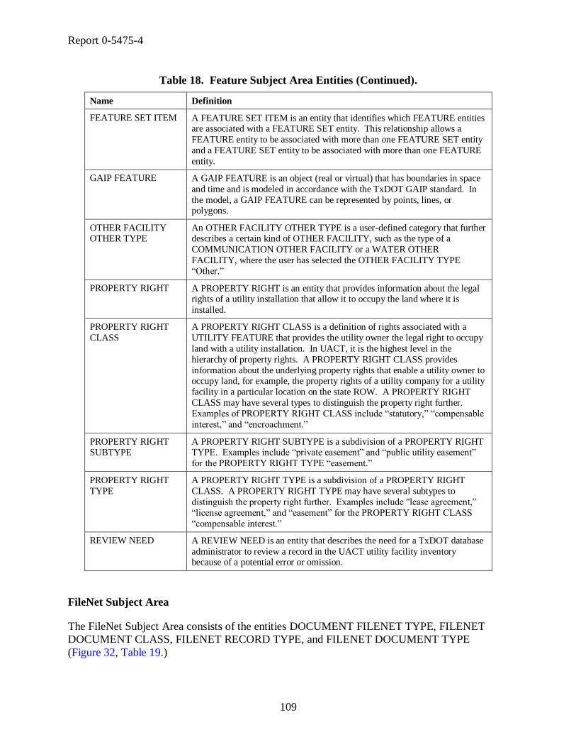
Report 0-5475-4
109
Table 18. Feature Subject Area Entities (Continued).
Name Definition
FEATURE SET ITEM A FEATURE SET ITEM is an entity that identifies which FEATURE entities are associated with a FEATURE SET entity. This relationship allows a
FEATURE entity to be associated with more than one FEATURE SET entity
and a FEATURE SET entity to be associated with more than one FEATURE
entity.
GAIP FEATURE A GAIP FEATURE is an object (real or virtual) that has boundaries in space
and time and is modeled in accordance with the TxDOT GAIP standard. In
the model, a GAIP FEATURE can be represented by points, lines, or polygons.
OTHER FACILITY OTHER TYPE
An OTHER FACILITY OTHER TYPE is a user-defined category that further describes a certain kind of OTHER FACILITY, such as the type of a
COMMUNICATION OTHER FACILITY or a WATER OTHER
FACILITY, where the user has selected the OTHER FACILITY TYPE
―Other.‖
PROPERTY RIGHT A PROPERTY RIGHT is an entity that provides information about the legal rights of a utility installation that allow it to occupy the land where it is
installed.
PROPERTY RIGHT
CLASS
A PROPERTY RIGHT CLASS is a definition of rights associated with a
UTILITY FEATURE that provides the utility owner the legal right to occupy
land with a utility installation. In UACT, it is the highest level in the
hierarchy of property rights. A PROPERTY RIGHT CLASS provides
information about the underlying property rights that enable a utility owner to occupy land, for example, the property rights of a utility company for a utility
facility in a particular location on the state ROW. A PROPERTY RIGHT
CLASS may have several types to distinguish the property right further.
Examples of PROPERTY RIGHT CLASS include ―statutory,‖ ―compensable
interest,‖ and ―encroachment.‖
PROPERTY RIGHT SUBTYPE
A PROPERTY RIGHT SUBTYPE is a subdivision of a PROPERTY RIGHT TYPE. Examples include ―private easement‖ and ―public utility easement‖
for the PROPERTY RIGHT TYPE ―easement.‖
PROPERTY RIGHT
TYPE
A PROPERTY RIGHT TYPE is a subdivision of a PROPERTY RIGHT
CLASS. A PROPERTY RIGHT TYPE may have several subtypes to
distinguish the property right further. Examples include "lease agreement,‖
―license agreement,‖ and ―easement‖ for the PROPERTY RIGHT CLASS
―compensable interest.‖
REVIEW NEED A REVIEW NEED is an entity that describes the need for a TxDOT database
administrator to review a record in the UACT utility facility inventory because of a potential error or omission.
FileNet Subject Area
The FileNet Subject Area consists of the entities DOCUMENT FILENET TYPE, FILENET
DOCUMENT CLASS, FILENET RECORD TYPE, and FILENET DOCUMENT TYPE
(Figure 32, Table 19.)
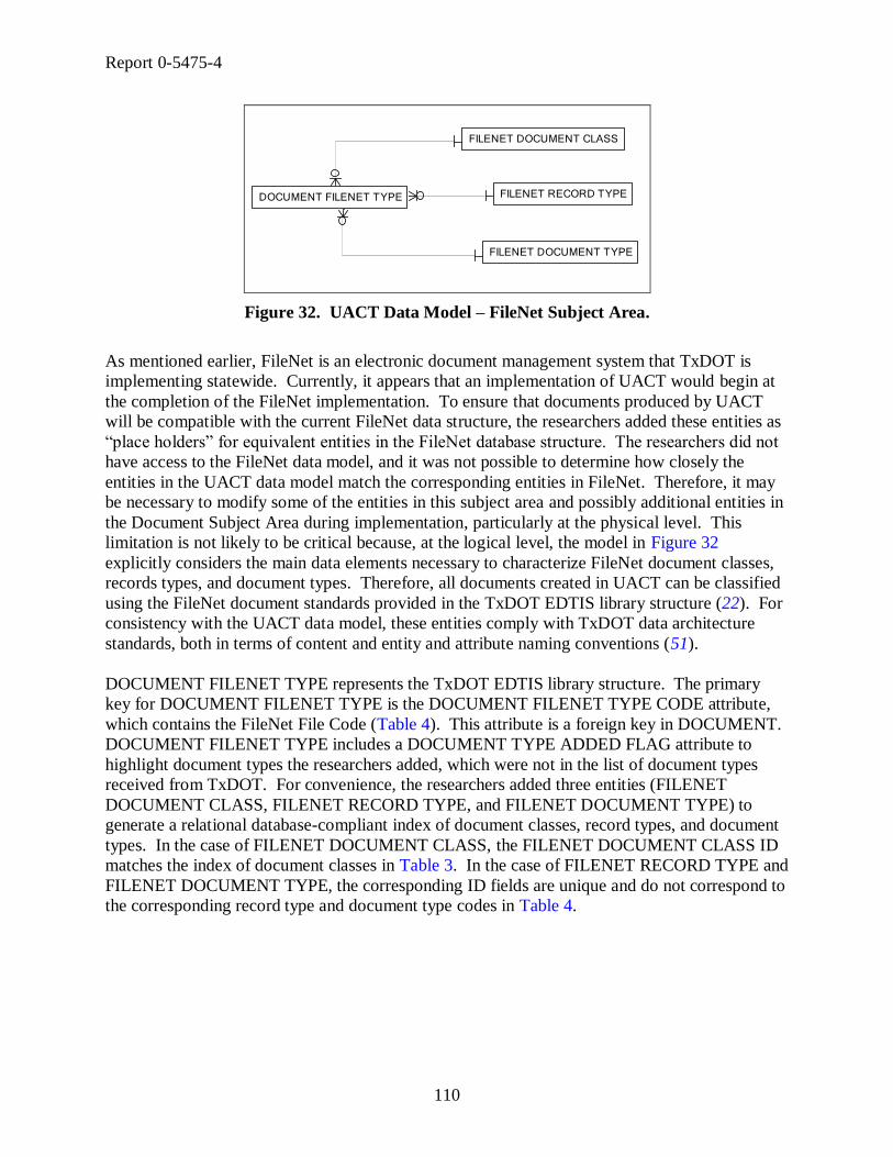
Report 0-5475-4
110
DOCUMENT FILENET TYPE FILENET RECORD TYPE
FILENET DOCUMENT TYPE
FILENET DOCUMENT CLASS
Figure 32. UACT Data Model – FileNet Subject Area.
As mentioned earlier, FileNet is an electronic document management system that TxDOT is
implementing statewide. Currently, it appears that an implementation of UACT would begin at
the completion of the FileNet implementation. To ensure that documents produced by UACT
will be compatible with the current FileNet data structure, the researchers added these entities as
―place holders‖ for equivalent entities in the FileNet database structure. The researchers did not
have access to the FileNet data model, and it was not possible to determine how closely the
entities in the UACT data model match the corresponding entities in FileNet. Therefore, it may
be necessary to modify some of the entities in this subject area and possibly additional entities in
the Document Subject Area during implementation, particularly at the physical level. This
limitation is not likely to be critical because, at the logical level, the model in Figure 32
explicitly considers the main data elements necessary to characterize FileNet document classes,
records types, and document types. Therefore, all documents created in UACT can be classified
using the FileNet document standards provided in the TxDOT EDTIS library structure (22). For
consistency with the UACT data model, these entities comply with TxDOT data architecture
standards, both in terms of content and entity and attribute naming conventions (51).
DOCUMENT FILENET TYPE represents the TxDOT EDTIS library structure. The primary
key for DOCUMENT FILENET TYPE is the DOCUMENT FILENET TYPE CODE attribute,
which contains the FileNet File Code (Table 4). This attribute is a foreign key in DOCUMENT.
DOCUMENT FILENET TYPE includes a DOCUMENT TYPE ADDED FLAG attribute to
highlight document types the researchers added, which were not in the list of document types
received from TxDOT. For convenience, the researchers added three entities (FILENET
DOCUMENT CLASS, FILENET RECORD TYPE, and FILENET DOCUMENT TYPE) to
generate a relational database-compliant index of document classes, record types, and document
types. In the case of FILENET DOCUMENT CLASS, the FILENET DOCUMENT CLASS ID
matches the index of document classes in Table 3. In the case of FILENET RECORD TYPE and
FILENET DOCUMENT TYPE, the corresponding ID fields are unique and do not correspond to
the corresponding record type and document type codes in Table 4.

Report 0-5475-4
111
Table 19. FileNet Subject Area Entities.
Name Definition
DOCUMENT FILENET TYPE
A DOCUMENT FILENET TYPE is a unique combination of a FileNet document class, record type, and document type that follows TxDOT’s
EDTIS Content Services library standards. In the standards, a file code
represents this unique combination. For example, file code 13.2.3 represents
a drainage easement document (document class = ―Right of Way,‖ record
type = ―Easement,‖ and document type = ―Drainage Easement.‖)
FILENET
DOCUMENT CLASS
A FILENET DOCUMENT CLASS is a category of documents within the
EDTIS Content Services library standards that corresponds to the highest level of aggregation of TxDOT business functions. Examples include
Administrative, Construction, Project Design, Right of Way, Traffic
Operations, and Transportation Planning.
FILENET DOCUMENT TYPE
A FILENET DOCUMENT TYPE is a type of document within a FILENET RECORD TYPE included in the EDTIS Content Services library standards.
The combination between FILENET RECORD TYPE and FILENET
DOCUMENT TYPE is unique within each FILENET DOCUMENT CLASS.
For example, the FILENET DOCUMENT TYPE ―Plan‖ is a type of
document within the FILENET RECORD TYPE ―Plans Specifications and
Estimates.‖ The combination between ―Plans Specifications and Estimates‖
and ―Plan‖ is unique within the FILENET DOCUMENT CLASS ―Project
Design.‖
FILENET RECORD TYPE
A FILENET RECORD TYPE is a document subclass within a FILENET DOCUMENT CLASS included in the EDTIS Content Services library
standards. For example, the FILENET RECORD TYPE ―Plans
Specifications and Estimates‖ is a document subclass within the FILENET
DOCUMENT CLASS ―Project Design.‖
MainStreet Texas Subject Area
The MainStreet Texas Subject Area consists of the entities DATASET CONNECTION,
DATASET FIELD, and DATASET TABLE (Figure 33, Table 20.) With the exception of
FEATURE CLASS, they are entities that reside on TxDOT servers and are maintained by
TxDOT.
DATASET TABLE
DATASET FIELD
DATABASE CONNECTION
Figure 33. UACT Data Model – MainStreet Texas Subject Area.
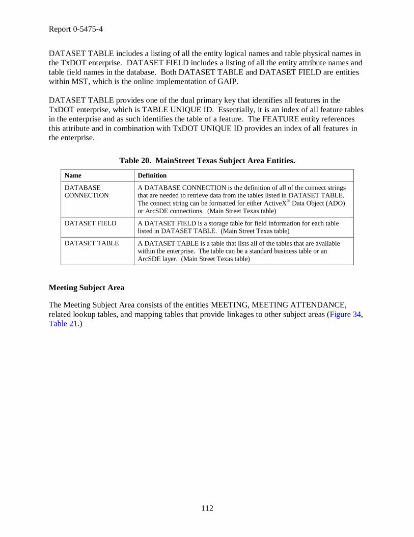
Report 0-5475-4
112
DATASET TABLE includes a listing of all the entity logical names and table physical names in
the TxDOT enterprise. DATASET FIELD includes a listing of all the entity attribute names and
table field names in the database. Both DATASET TABLE and DATASET FIELD are entities
within MST, which is the online implementation of GAIP.
DATASET TABLE provides one of the dual primary key that identifies all features in the
TxDOT enterprise, which is TABLE UNIQUE ID. Essentially, it is an index of all feature tables
in the enterprise and as such identifies the table of a feature. The FEATURE entity references
this attribute and in combination with TxDOT UNIQUE ID provides an index of all features in
the enterprise.
Table 20. MainStreet Texas Subject Area Entities.
Name Definition
DATABASE CONNECTION
A DATABASE CONNECTION is the definition of all of the connect strings that are needed to retrieve data from the tables listed in DATASET TABLE.
The connect string can be formatted for either ActiveX® Data Object (ADO)
or ArcSDE connections. (Main Street Texas table)
DATASET FIELD A DATASET FIELD is a storage table for field information for each table listed in DATASET TABLE. (Main Street Texas table)
DATASET TABLE A DATASET TABLE is a table that lists all of the tables that are available within the enterprise. The table can be a standard business table or an
ArcSDE layer. (Main Street Texas table)
Meeting Subject Area
The Meeting Subject Area consists of the entities MEETING, MEETING ATTENDANCE,
related lookup tables, and mapping tables that provide linkages to other subject areas (Figure 34,
Table 21.)

Report 0-5475-4
113
MEETING TYPE
MEETING
MEETING ATTENDANCE
UTILITY CONFLICT MEETING
PROJECT MEETING
MEETING DOCUMENT
MEETING NOTE
Figure 34. UACT Data Model – Meeting Subject Area.
MEETING provides the ability to store information about meetings in UACT. A user that
creates a new meeting in UACT must provide a meeting name, description, start date, end date,
location, and type. The system automatically assigns a meeting ID, creates a timestamp, and
stores the user ID with each meeting. MEETING NOTE allows the association of notes with a
meeting, and similarly MEETING DOCUMENT, UTILITY CONFLICT MEETING, and
PROJECT MEETING allow association of a meeting with documents, utility conflicts, and
projects, respectively. MEETING ATTENDANCE is a mapping between a meeting and UACT
users to facilitate the association of UACT users with a meeting. For example, this entity would
be useful when a meeting organizer wants to invite all utility owners that are stakeholders of a
project to a utility coordination meeting. PROJECT MEETING would associate the meeting
with a project, and MEETING ATTENDANCE would track the participants of that meeting.

Report 0-5475-4
114
Table 21. Meeting Subject Area Entities.
Name Definition
MEETING A MEETING is a gathering of TxDOT employees and/or other project-related companies at a predetermined date and time for the purpose of
discussing project-related matters.
MEETING
ATTENDANCE
A MEETING ATTENDANCE is the requirement or the recommendation that
a SYSTEM USER attend a MEETING. MEETING ATTENDANCE maps
MEETINGs to SYSTEM USERs.
MEETING
DOCUMENT
A MEETING DOCUMENT is a mapping between the entities MEETING
and DOCUMENT to associate all MEETINGS with a DOCUMENT and all
DOCUMENTS with a MEETING.
MEETING NOTE A MEETING NOTE is a mapping between a NOTE and a MEETING allowing a SYSTEM USER to provide additional information about a
MEETING.
MEETING TYPE A MEETING TYPE is a category that defines a certain kind of MEETING.
PROJECT MEETING A PROJECT MEETING is a mapping between PROJECT and MEETING that describes a MEETING containing discussion about a PROJECT.
UTILITY CONFLICT MEETING
A UTILITY CONFLICT MEETING is a mapping between UTILITY CONFLICT and MEETING for the purpose to associate a MEETING with a
UTILITY CONFLICT and vice versa.
Permissions Subject Area
The Permissions Subject Area consists of the entities ROLE, PERMISSION, CAPABILITY,
BUSINESS AREA, BUSINESS AREA SECTION, and mapping tables (Figure 35, Table 24.)
ROLE
CAPABILITYDEFAULT ROLE PERMISSION
EFFECTIVE USER PERMISSION
DEFAULT ROLE PERMISSION PRIVILEGE
BUSINESS AREA
BUSINESS AREA SECTION
PERMISSION
Figure 35. UACT Data Model – Permissions Subject Area.
Experience with the implementation of the UIR system has shown that maintaining a strict
workflow-control system for the specific tasks supported by UACT would result in an unfeasible
level of administrative overhead. Instead, the researchers designed a permissions-based system
that allows any user to make changes at any time that are within his or her level of access. The

Report 0-5475-4
115
UACT permissions model provides highly detailed user access levels, mapping of companies,
functions in the Project Development Process, and user groups that the system combines to a
user-specific set of application capabilities.
In the UIR system, permissions and access to documents are controlled by individual users that
are part of a pre-defined workflow. Only the user with current control of a document can make
modifications to that document. To enable another user to modify a document, a user must
relinquish control of the document and send it to the second user who then gains control of the
document. The UIR system controls access to documents by controlling the user’s document
distribution options at any given point in the workflow. The UACT system varies from this
method in a way that it does not contain a strict workflow but access to a document or an
area/function of the system is based on strictly defined permissions that are combinations of a
capability with a business area section. Capabilities are the system’s basic user actions, which
are:
view,
add,
edit,
delete, and
upload.
In UACT, business areas are zones that the researchers defined to restrict user access to portions
of the prototype. Business areas have subdivisions called business area sections that the
researchers used to further restrict user access. Table 22 shows UACT’s business areas and
business area sections:

Report 0-5475-4
116
Table 22. UACT Business Areas and Business Area Sections.
Business Area Business Area Section
Project Project Listing
New UACT Project
Project Details
Project Status
Project Stakeholders
Project Documents
Utility Inventory Project Utility Listing
Enterprise Utility Listing
Utility Details
New Utility
Conflict Tracking Conflict Listing
Conflict Details
Conflict Documents
Conflict Notes
New Conflict
Agreement Assembly Agreement Listing
Agreement Details
New Agreement
Reports Reports
Contacts Contacts Listing
Other Resources Other Resources
New Resource
Users User Listing
User Details
New User
Access Control System Permissions
Role Permissions
Privilege Permissions
In UACT, a permission must be defined before it can be associated with a user because not every
business area section has all capabilities. To create a UACT permission, a system administrator
must associate a capability with a business area section, for example capability ―view‖ with
business area section ―Project Summary.‖ Once a permission is defined, it can be associated
with a user. To assign several permissions to a user in one step, a system administrator can
define a UACT role, which describes a function that a system user or company may perform in
the TxDOT PDP, e.g., ―Utility Owner.‖ The administrator can then associate several
permissions with that role. When a company creates a new account in the UACT system, a
system administrator can assign the role to the account, which defines all permissions for the

Report 0-5475-4
117
account in one step. The UACT Access Matrix shows 16 roles with associated access
permissions that the UACT prototype currently defines along with business area sections and
capabilities (Table 23). Figure 36 shows how the roles utility owner, SUE provider, and TxDOT
encompass subsets of UACT permissions, some of which are shared (overlapping areas).
Figure 36. Relationship of Roles and Permissions in UACT.
The permissions of a UACT user are limited by the user’s role. They can be further restricted by
the company administrator using a privilege. A privilege is a subset of permissions that a role
has. For example, a utility owner may want to set up three levels of access for his employees:
―Administrator,‖ which includes all permissions of the utility owner role, ―User,‖ which includes
most of the utility owner permissions, and ―Guest,‖ which includes only the view permissions of
a utility owner role. Figure 37 shows how the privileges Administrator, User, and Guest define
subsets of permissions within the role TxDOT.
Figure 37. Relationship of Roles and Privileges in UACT.

Report 0-5475-4
118
In the data model, CAPABILITY stores a listing of capabilities, ROLE stores a listing of the
system’s roles, and BUSINESS AREA SECTION stores a listing of business area sections
associated with a business area. Permissions that are associated by default with a role are stored
in DEFAULT ROLE PERMISSION. DEFAULT ROLE PERMISSION PRIVILEGE stores the
association of any default role permission with a privilege, in other words, which of the
permissions associated with a certain role belong to a certain privilege within that role.
To give the system additional flexibility, the researchers created the table EFFECTIVE USER
PERMISSION, which is the main table that defines a user’s permissions and access to UACT
(Figure 35). The table references four keys, which are CONTROL SECTION JOB NUMBER,
DEFAULT ROLE PERMISSION PRIVILEGE ID, PERMISSION ID, AND SYSTEM USER
ID and then assigns an EFFECTIVE USER PERMISSION ID. Essentially, only DEFAULT
ROLE PERMISSION PRIVILEGE ID and SYSTEM USER ID would have been required to
identify a system user’s access. However, adding the reference to PERMISSION ID allows a
system administrator to assign any permission to any user if there is a need for it. By adding the
reference to CONTROL SECTION JOB NUMBER, the system administrator can limit any
additional permission to one or more specific projects. Since DEFAULT ROLE PERMISSION
PRIVILEGE ID is not part of the primary key, it is also possible for a system administrator to
provide all permissions for a specific user directly without specifying a role or privilege. In
summary, this data model design allows for a convenient mechanism to assign default
permissions to certain types of users while providing the greatest possible flexibility of assigning
permissions to user when needed.

Report 0-5475-4
119
Table 23. UACT Access Matrix.
Permissions Roles
Business
Area
Business Area
Section Cap.
Perm.
ID
UACT System
Administrator
TxDOT District
ROW
Administrator
TxDOT ROW
Division
Reviewer
TxDOT
District Utility
Coordinator
Consultant
Utility
Coordinator
TxDOT District
Design Project
Manager
TxDOT
District
Designer
TxDOT
Surveyor
Consultant
Surveyor
SUE
Consultant
Utility
Owner
Utility
Consultant LPA
Utility
Contractor
Highway
Project
Contractor
ROW
Acquisition
Consultant
Project Project Listing View 1 Yes Yes Yes Yes Yes Yes Yes Yes Yes Yes Yes Yes Yes Yes Yes Yes
View 2 Yes Yes Yes No No No No No No No No No No No No No
Add 3 Yes Yes Yes No No No No No No No No No No No No No
View 4 Yes Yes Yes Yes Yes Yes Yes Yes Yes Yes Yes Yes Yes Yes Yes Yes
Edit 5 Yes Yes Yes Yes No No No No No No No No No No No No
Delete 6 Yes Yes Yes Yes No No No No No No No No No No No No
Project Status View 7 Yes Yes Yes Yes Yes Yes Yes Yes No No No No No No No No
View 8 Yes Yes Yes Yes Yes Yes Yes Yes Yes Yes Yes Yes Yes Yes Yes Yes
Edit 9 Yes Yes Yes Yes Yes No No No No No No No No No No No
Add 10 Yes Yes Yes Yes Yes Yes Yes No No No No No No No No No
Delete 11 Yes Yes Yes Yes Yes No No No No No No No No No No No
View 12 Yes Yes Yes Yes Yes Yes Yes Yes Yes Yes Yes Yes Yes Yes Yes Yes
Edit 13 Yes Yes Yes Yes Yes Yes Yes Yes Yes Yes Yes Yes Yes Yes Yes Yes
Add 14 Yes Yes Yes Yes Yes Yes Yes Yes Yes Yes Yes Yes Yes Yes Yes Yes
Delete 15 Yes Yes Yes Yes Yes Yes Yes Yes Yes Yes Yes Yes Yes Yes Yes Yes
Project Utility Listing View 16 Yes Yes Yes Yes Yes Yes Yes Yes Yes Yes Yes Yes Yes Yes Yes No
View 17 Yes Yes Yes Yes Yes Yes Yes Yes Yes Yes Yes Yes Yes Yes Yes No
Edit 18 Yes Yes Yes Yes Yes Yes Yes Yes Yes Yes No No No No No No
Delete 19 Yes Yes Yes Yes Yes Yes Yes Yes No No No No No No No No
View 20 Yes Yes Yes Yes Yes Yes Yes Yes No No No No No No No No
Add 21 Yes Yes Yes Yes Yes Yes Yes Yes No No No No No No No No
View 22 Yes Yes Yes Yes Yes Yes Yes Yes Yes Yes Yes Yes Yes No No No
Add 23 Yes Yes Yes Yes Yes Yes Yes Yes Yes Yes Yes Yes Yes No No No
Conflict Listing View 24 Yes Yes Yes Yes Yes Yes Yes Yes Yes Yes Yes Yes Yes Yes Yes No
View 25 Yes Yes Yes Yes Yes Yes Yes Yes Yes Yes Yes Yes Yes Yes Yes No
Edit 26 Yes Yes Yes Yes Yes Yes Yes Yes Yes Yes No No No No No No
Delete 27 Yes Yes Yes Yes Yes Yes Yes Yes No No No No No No No No
View 28 Yes Yes Yes Yes Yes Yes Yes Yes Yes Yes Yes Yes Yes Yes Yes No
Add 29 Yes Yes Yes Yes Yes Yes Yes Yes Yes Yes Yes Yes Yes No No No
View 30 Yes Yes Yes Yes Yes Yes Yes Yes Yes Yes Yes Yes Yes Yes Yes No
Edit 31 Yes Yes Yes Yes Yes Yes Yes Yes Yes Yes Yes Yes Yes Yes Yes No
Add 32 Yes Yes Yes Yes Yes Yes Yes Yes Yes Yes Yes Yes Yes Yes Yes No
Delete 33 Yes Yes Yes Yes Yes Yes Yes Yes Yes Yes Yes Yes Yes Yes Yes No
View 34 Yes Yes Yes Yes No Yes Yes Yes No No No No No No No No
Edit 35 Yes Yes Yes Yes No Yes Yes Yes No No No No No No No No
Add 36 Yes Yes Yes Yes No Yes Yes Yes No No No No No No No No
Delete 37 Yes Yes Yes Yes No Yes Yes Yes No No No No No No No No
Agreement Agreement Listing View 38 Yes Yes Yes Yes Yes Yes Yes Yes No No Yes Yes Yes Yes Yes No
View 39 Yes Yes Yes Yes Yes Yes Yes Yes No No Yes Yes Yes Yes Yes No
Edit 40 Yes Yes Yes Yes Yes No No No No No Yes Yes Yes No No No
Delete 41 Yes Yes Yes Yes Yes No No No No No Yes Yes Yes No No No
View 42 Yes Yes Yes Yes No No No No No No Yes Yes Yes No No No
Add 43 Yes Yes Yes Yes No No No No No No Yes Yes Yes No No No
Reports Reports View 44 Yes Yes Yes Yes Yes Yes Yes Yes No No No No No No No No
Contacts Contacts Listing View 45 Yes Yes Yes Yes Yes Yes Yes Yes Yes Yes Yes Yes Yes Yes Yes Yes
Other Resources View 46 Yes Yes Yes Yes Yes Yes Yes Yes Yes Yes Yes Yes Yes Yes Yes Yes
View 47 Yes Yes Yes Yes No Yes Yes Yes No No No No No No No No
Edit 48 Yes Yes Yes Yes No Yes Yes Yes No No No No No No No No
Add 49 Yes Yes Yes Yes No Yes Yes Yes No No No No No No No No
Delete 50 Yes Yes Yes Yes No Yes Yes Yes No No No No No No No No
User Listing View 51 Yes Yes Yes Yes Yes Yes Yes Yes Yes Yes Yes Yes Yes Yes Yes No
View 52 Yes Yes Yes Yes Yes Yes Yes Yes Yes Yes Yes Yes Yes Yes Yes No
Edit 53 Yes Yes Yes Yes Yes Yes Yes Yes Yes Yes No No No No No No
Delete 54 Yes Yes Yes Yes Yes Yes Yes Yes No No No No No No No No
View 55 Yes Yes Yes Yes Yes Yes Yes Yes Yes Yes Yes Yes Yes Yes Yes No
Add 56 Yes Yes Yes Yes Yes Yes Yes Yes Yes Yes Yes Yes Yes No No No
View 57 Yes Yes Yes Yes Yes No No No No No No No No No No No
Edit 58 Yes Yes Yes Yes Yes No No No No No No No No No No No
Add 59 Yes Yes Yes Yes Yes No No No No No No No No No No No
Delete 60 Yes Yes Yes Yes Yes No No No No No No No No No No No
View 61 Yes Yes Yes Yes Yes No No No No No No No No No No No
Edit 62 Yes Yes Yes Yes Yes No No No No No No No No No No No
Add 63 Yes Yes Yes Yes Yes No No No No No No No No No No No
Delete 64 Yes Yes Yes Yes Yes No No No No No No No No No No No
View 65 Yes Yes Yes Yes Yes No No No No No No No No No No No
Edit 66 Yes Yes Yes Yes Yes No No No No No No No No No No No
Add 67 Yes Yes Yes Yes Yes No No No No No No No No No No No
Delete 68 Yes Yes Yes Yes Yes No No No No No No No No No No No
Conflict Details
New Utility
Conflict
Tracking
Utility Inventory
Other
Resources
Users
User Details
Utility Details
New User
Role Permissions
System Permissions
Access Control
Project Stakeholders
Project Documents
New UACT Project
Project Details
Enterprise Utility Listing
New Agreement
Agreement Details
Conflict Notes
Conflict Documents
New Conflict
Privilege Permissions
New Resource


Report 0-5475-4
121
Table 24. Permissions Subject Area Entities.
Name Definition
BUSINESS AREA A BUSINESS AREA is a grouping of BUSINESS AREA SECTIONS according to their functionality and common business purpose, e.g., Project,
Conflict, Utility Agreement, etc.
BUSINESS AREA
SECTION
A BUSINESS AREA SECTION is an area of the application that is made up
of a collection of processes or tasks (like adding, importing, or deleting).
CAPABILITY A CAPABILITY is an individual action that a SYSTEM USER can perform
in the application. Examples of a CAPABILITY are Add, Edit, Delete,
Import, or Upload.
DEFAULT ROLE
PERMISSION
A DEFAULT ROLE PERMISSION is a specification of the capabilities that
a ROLE has by default. In other words, it is a mapping of ROLE and PERMISSION to provide default permissions for a ROLE.
DEFAULT ROLE PERMISSION
PRIVILEGE
A DEFAULT ROLE PERMISSION PRIVILEGE is a mapping between DEFAULT ROLE PERMISSION and PRIVILEGE to define the permissions
of a user account with a certain PRIVILEGE within a certain ROLE. This
entity allows an administrative user of a certain role to assign permissions to a
PRIVILEGE within that ROLE.
EFFECTIVE USER PERMISSION
An EFFECTIVE USER PERMISSION defines the permissions of a SYSTEM USER within the system. This entity allows a TxDOT
administrator to modify the default permissions of a SYSTEM USER and to
add any PERMISSION to a SYSTEM USER, either for all projects or only
certain projects.
PERMISSION PERMISSION is a joining of BUSINESS AREA SECTION and
CAPABILITY, which results in a set of functions that can be performed in
UACT. For example, ―Edit Project‖ is a PERMISSION that is a combination of the CAPABILITY ―Edit‖ and the BUSINESS AREA SECTION ―Project.‖
ROLE A ROLE is a function that a SYSTEM USER or a COMPANY may perform for TxDOT in the Project Development Process. Examples of a ROLE
include ―Project Manager,‖ ―Surveyor,‖ ―SUE Provider‖ and ―Utility
Coordinator.‖
Project Subject Area
The Project Subject Area consists of the main entities DCIS PROJECT, UACT PROJECT,
PROJECT EVENT, ROW PROJECT, ALIGNMENT, related lookup tables, and mapping tables
that provide linkages to other subject areas (Figure 38, Table 25.)

Report 0-5475-4
122
UACT PROJECTPROJECT EVENT
PROJECT EVENT TYPE
PROJECT ACTIVITY GROUP STATUSPROJECT ANCESTOR
PROJECT ACTIVITY GROUP
PROJECT FEATURE
PROJECT MANAGER TYPE
PROJECT MANAGER
ROWIS CONNECTION
ROW PROJECT FINANCIAL INFORMATION MANAGEMENT SYSTEM
ROW PROJECT FUNDING TYPE
ROW PROJECT CONTRACT TYPE
UTILITY ADJUSTMENT PROCEDURE
PROJECT UTILITY ADJUSTMENT PROCEDURE
PROJECT EVENT TYPE PROJECT EVENT
ALIGNMENT
CUSTOM ALIGNMENT
ALIGNMENT PROJECT
DCIS PROJECT
Figure 38. UACT Data Model – Project Subject Area.
DCIS PROJECT is the normalized data repository for data that the system receives from DCIS.
The primary key of DCIS PROJECT is CONTROL SECTION JOB NUMBER. Typically,
TxDOT projects start out with a planning or temporary CSJ number until the project is
authorized. After authorization, TxDOT assigns a permanent CSJ number to the project.
Occasionally, a project may be combined or split, which may create a number of parent CSJ
numbers. To track these changes, the DCIS File 121 includes five attribute fields (ANCESTOR
CSJ1 – ANCESTOR CSJ5) that track up to five changes to CSJs that are also included in DCIS
DATA WAREHOUSE.
As mentioned in the discussion of the DCIS Subject Area, DCIS DATA WAREHOUSE serves
as the non-normalized data repository for data from DCIS File 121 (see Figure 29). Once a
download is complete, data is copied through UACT code from DCIS DATA WAREHOUSE
into DCIS PROJECT and PROJECT ANCESTOR and normalized in the process. For example,
LAYMAN DESCRIPTION1 and LAYMAN DESCRIPTION2 in DCIS DATA WAREHOUSE
are combined to DCIS PROJECT DESCRIPTION in DCIS PROJECT. Further, the fields
ANCESTOR CSJ1 through ANCESTOR CSJ5 are copied to PROJECT ANCESTOR and stored
in CSJ PARENT NUMBER and associated with a project through CONTROL SECTION
NUMBER referenced from DCIS PROJECT. Providing a dual-storage for project data also
allows the comparison of the data from one data download to the next. Since the data in DCIS
DATA WAREHOUSE is overwritten with every download, DCIS PROJECT allows a check for
changes of the new data download. The researchers envision that during an implementation, a
quality control mechanism will alert the system administrator of changes to the DCIS before
committing changes to DCIS PROJECT.
DCIS is the repository for project data of all TxDOT projects. Because not all projects are
impacted by utilities, it is necessary to identify the projects that do have a utility component and
track only those projects in UACT. The entity UACT PROJECT entity is a filter of projects that
are impacted by utilities and should be managed in UACT, which makes UACT PROJECT one

Report 0-5475-4
123
of the core entities of the UACT data model. UACT PROJECT also allows the designation of a
project alias, and provides a linkage to several other subject areas such as ROWIS
CONNECTION, which links to ROWIS, PROJECT DOCUMENT, which links projects to
document, PROJECT FEATURE, which links projects to features, and PROJECT COMPANY,
which links projects to companies.
ROWIS CONNECTION is a mapping between UACT PROJECT and the PROJECTS table in
ROWIS that resolves a many-to-many relationship between the two tables. ROWIS
CONNECTION associates a CONTROL SECTION ID from UACT PROJECT with a
PROJECT ID from the PROJECTS table. As such, it should be possible to query any ROWIS
data associated with a project in ROWIS as long as the primary project identifier or CSJ is
known in UACT, provided that there is a physical connection between the two systems. This
connection is the most basic form of integration between the two systems. During an
implementation, it may be feasible to pursue a deeper level of integration between the two
systems using additional associative tables or foreign-key constraints in UACT entities.
Similar to ROWIS CONNECTION, PROJECT DOCUMENT is a mapping between UACT
PROJECT and DOCUMENT that resolves a many-to-many relationship between the two tables.
Through PROJECT DOCUMENT, it is possible to associate a project with many documents and
one document with many projects. PROJECT FEATURE and PROJECT COMPANY serve
analogous roles to resolve many-to-many relationships between projects and features as well as
projects and companies.
The ALIGNMENT entity provides the names of possible alignments in a project such as
―Proposed Centerline‖ that may be used in combination with the alignment’s stationing as a
reference for the location of utility conflicts. ALIGNMENT presents an alternative to the
PROJECT LINE feature described in the ArcSDE Subject Area if the project does not have a
suitable project line feature available at the time a utility conflict is created (see Figure 28). In
that case, a system administrator may create a record in ALIGNMENT to use as a non-spatial
reference for utility conflicts.

Report 0-5475-4
124
Table 25. Project Subject Area Entities.
Name Definition
ALIGNMENT An ALIGNMENT is a pre-defined horizontal reference line to determine the relative location of a conflict, as compared to user-defined horizontal
reference lines, which are stored in CUSTOM ALIGNMENT. Examples of
ALIGNMENT are ―Proposed right of way line‖ and ―Existing main lane
centerline.‖
ALIGNMENT
PROJECT
An ALIGNMENT PROJECT is a mapping between the entities
ALIGNMENT and PROJECT to resolve a many-to-many relationship
between these two entities.
CUSTOM ALIGNMENT
A CUSTOM ALIGNMENT is a user-defined horizontal reference line to determine the relative location of a conflict, as compared to pre-defined
horizontal reference lines, which are stored in ALIGNMENT. The purpose of
CUSTOM ALIGNMENT is to store project-specific alignments. An example
of a CUSTOM ALIGNMENT is ―Southbound IH-10 frontage road
centerline.‖
DCIS PROJECT A DCIS PROJECT is a TxDOT roadway improvement project whose data is entered into the TxDOT DCIS WAREHOUSE, is normalized, and then
imported into this table.
FINANCIAL
INFORMATION
MANAGEMENT
SYSTEM
A FINANCIAL INFORMATION MANAGEMENT SYSTEM is a TxDOT
accounting system maintained by the Finance Division and made up of
approximately 35 segments and 700 programs. Source: TxDOT Glossary 02-
2006.
PROJECT ACTIVITY
GROUP
A PROJECT ACTIVITY GROUP is a collection or aggregation of activities
in the project development process. Examples include ―Right Of Way Acquisition‖ and ―Detailed Design.‖
PROJECT ACTIVITY GROUP STATUS
A PROJECT ACTIVITY GROUP STATUS is the state of a PROJECT ACTIVITY GROUP at any given point in time. Examples include ―30%
Right Of Way Acquisition complete, ‖ ―60% Detailed Design complete, ‖ etc.
PROJECT ANCESTOR
A PROJECT ANCESTOR is a mapping between a CONTROL SECTION JOB NUMBER and one or more CSJ PARENT NUMBERs, if the parent CSJ
number exists.
PROJECT EVENT A PROJECT EVENT is a creation or modification of a PROJECT.
PROJECT EVENT TYPE
A PROJECT EVENT TYPE is the category that describes a certain kind of PROJECT EVENT.
PROJECT EVENT TYPE PROJECT
EVENT
A PROJECT EVENT TYPE PROJECT EVENT is a mapping between the entities PROJECT EVENT TYPE and PROJECT EVENT to resolve a many-
to-many relationship between these two entities.
PROJECT FEATURE A PROJECT FEATURE is a mapping that represents the many-to-many
relationship between a PROJECT and a FEATURE. PROJECT FEATURE
enables the identification of FEATURES associated with a PROJECT and the
identification of PROJECTS associated with a FEATURE.
PROJECT MANAGER A PROJECT MANAGER serves as a record of all managers who manage a PROJECT.
PROJECT MANAGER TYPE
A PROJECT MANAGER TYPE is the job description of a PROJECT MANAGER.

Report 0-5475-4
125
Table 25. Project Subject Area Entities (Continued).
Name Definition
PROJECT UTILITY ADJUSTMENT
PROCEDURE
A PROJECT UTILITY ADJUSTMENT PROCEDURE is an association of a PROJECT with a UTILITY ADJUSTMENT PROCEDURE. The purpose of
this association entity is to resolve a many-to-many relationship between the
two entities.
ROW PROJECT A ROW PROJECT is a TxDOT roadway improvement project that involves
the TxDOT ROW Division.
ROW PROJECT
CONTRACT TYPE
A ROW PROJECT CONTRACT TYPE is a property that categorizes the
type of ROW PROJECT CONTRACT.
ROW PROJECT
FUNDING TYPE
A ROW PROJECT FUNDING TYPE is a property that categorizes the type
of ROW PROJECT FUNDING.
ROWIS CONNECTION
A ROWIS CONNECTION is a mapping that represents the many-to-many relationship between a DCIS PROJECT and a ROWIS PROJECT. ROWIS
CONNECTION links zero, one, or more CSJs to zero, one, or more ROWIS
PROJECT IDs and so enables the identification of project-related information
from ROWIS.
UACT PROJECT A UACT PROJECT is a TxDOT roadway improvement project that is managed and tracked in the UACT application. The data of a UACT
PROJECT is mostly derived from a DCIS PROJECT.
UTILITY ADJUSTMENT
PROCEDURE
A UTILITY ADJUSTMENT PROCEDURE is a process to accomplish the adjustment and accommodation of reimbursable utility facilities on TxDOT
projects. Source: TxDOT Utility Manual
ROWIS Subject Area
The ROWIS Subject Area consists of the entities PROJECTS, CONTROL SECTION JOBS,
PARCELS, and a related mapping table CONTROL SECTION JOBS PARCELS (Figure 39,
Table 26.)
CONTROL SECTION JOBSPROJECTS
CONTROL SECTION JOBS PARCELS PARCELS
Figure 39. UACT Data Model – ROWIS Subject Area.
All tables in this subject area are components of ROWIS and maintained by TxDOT. For
simplicity, the researchers only included some of the attributes in the data model that are relevant
to UACT.

Report 0-5475-4
126
During an implementation of UACT, it would be critical to access and display data in UACT that
are maintained in ROWIS. The data in ROWIS are stored in a RDBMS using an implementation
of Microsoft SQL Server. As such, accessing data from ROWIS and displaying the data in
UACT is conceptually much less difficult as compared to data that originated from DCIS. The
logical model allows the linking of data in UACT and ROWIS through an associative entity
called ROWIS CONNECTION as described in the Project Subject Area.
Table 26. ROWIS Subject Area Entities.
Name Definition
CONTROL SECTION JOBS
No definition found in the ROWIS data model (ERwin format) TxDOT provided. Apparently, a CONTROL SECTION JOBS is a table that provides
a linkage between different types of CSJ numbers (Construction, ROW) and a
project, and for each CSJ assigns a different unique CSJ identifier for the
system. (ROWIS table)
CONTROL SECTION
JOBS PARCELS
No definition found in the ROWIS data model (ERwin format) TxDOT
provided. Apparently, a CONTROL SECTION JOBS PARCELS is a linking
table between CONTROL SECTION JOBS and the PARCELS table for the purpose of identifying which parcels are located on a control section job and
which control section jobs a parcel is located on, to satisfy the many-to-many
relationship between PARCELS and CONTROL SECTION JOBS. (ROWIS
table)
PARCELS No definition found in the ROWIS data model (ERwin format) TxDOT provided. Apparently PARCELS is a listing of parcel information that
pertains to a right of way property parcel including, number, release date,
possession date, etc. (ROWIS table)
PROJECTS No definition found in the ROWIS data model (ERwin format) TxDOT
provided. Apparently, PROJECTS is a listing of project information that
pertains to TxDOT right of way project, including right of way release date,
environmental clearance date, total authorized state funds, etc. (ROWIS
table)
System Subject Area
The System Subject Area consists of the entities MESSAGE, MESSAGE TYPE, and UACT
ENTITY (Figure 40, Table 27.)

Report 0-5475-4
127
UACT ENTITY
MESSAGE
MESSAGE TYPE
Figure 40. UACT Data Model – System Subject Area.
UACT ENTITY is a listing of all entities in the UACT data model including the definition of the
entity. The purpose of UACT ENTITY is to make entity definition accessible to the system.
The definitions are stored in the entity properties of the ERwin data model file but cannot be
exported during database schema creation. UACT ENTITY provides an easy access to the entity
definitions, which allows for the creation of Extensible Markup Language (XML) files that can
be used for the context-relevant help that UACT displays in several areas of the system.
MESSAGE and MESSAGE TYPE are UACT system tables that allow UACT system designers
to store standard error messages for various pages and processes.
Table 27. System Subject Area Entities.
Name Definition
MESSAGE A MESSAGE is a phrase or sentence used in the UACT application to convey
information to users.
MESSAGE TYPE A MESSAGE TYPE is a category that describes a certain kind of
MESSAGE. Examples of a MESSAGE TYPE are ―error message‖ and ―warning message.‖
UACT ENTITY A UACT ENTITY is a representation of a table in the UACT data model.
Utility Agreement Assembly Subject Area
The Utility Agreement Assembly Subject Area consists of the main entities UTILITY
AGREEMENT, UTILITY AGREEMENT ASSEMBLY, UTILITY AGREEMENT
ASSEMBLY EVENT, UTILITY JOINT USE ACKNOWLEDGEMENT, PAYMENT,
UTILITY BILL, related lookup tables, and mapping tables that provide linkages to other subject
areas (Figure 41, Table 29.)

Report 0-5475-4
128
UTILITY AGREEMENT ASSEMBLY
UTILITY AGREEMENT ASSEMBLY UTILITY CONFLICT
PAYMENT PAYMENT TYPE
ESTIMATE
ESTIMATE TYPE
UTILITY BILL UTILITY BILL TYPE
UTILITY AGREEMENT ASSEMBLY EVENT
UTILITY AGREEMENT ASSEMBLY EVENT TYPE
UTILITY JOINT USE ACKNOWLEDGEMENT
UTILITY JOINT USE ACKNOWLEDGEMENT EVENT
UJUA EVENT TYPE
SUBSEQUENT ENCUMBRANCE
UTILITY AGREEMENT ASSEMBLY REIMBURSEMENT APPROACH
UAA CONTRACTING PROCEDURE TYPE
PRE QUALIFIED CONTRACTOR
ELIGIBILITY RATIO
ELIGIBILITY RATIO TYPE
UTILITY AGREEMENT
SCOPE OF WORK
SCOPE OF WORK LOCATION
SCOPE OF WORK LOCATION TYPE
QUITCLAIM DEED
ACCOUNTING METHOD
COMPOSITE ELIGIBILITY RATIO
ELIGIBILITY RATIO PROPERTY RIGHT OCCUPANCY
UAA PRE QUALIFIED CONTRACTOR
UTILITY AGREEMENT ASSEMBLY ATTACHMENT
UTILITY AGREEMENT ASSEMBLY SEQUENCE
UAA ATTACHMENT COMPLETION INDICATOR
UAA UTILITY ADJUSTMENT TYPE
WORK SCHEDULE OVERVIEW
UAA PROPERTY INTEREST PROOF TYPE
MEASUREMENT UNIT
Figure 41. UACT Data Model – Utility Agreement Assembly Subject Area.
The Utility Agreement Assembly Subject Area has the largest number of entities of all UACT
subject areas. These entities are required to store and provide data about utility agreement
assemblies and the cost reimbursement process following a reimbursable utility adjustment. The
design of this portion of the data model resulted from an initial data model design based on
feedback from stakeholders that the researchers combined with the functionality of the ROW
Division’s UAD. Based on an analysis of the UAD data architecture, the researchers created a
normalized UAD data model and then created several new UACT entities to reproduce the
functionality of the UAD within the UACT data model. An implementation of the UACT
prototype should allow for a complete migration of the UAD data into UACT and allow UACT
to replace the UAD.
UTILITY AGREEMENT ASSEMBLY is the central entity of the subject area. Its purpose is to
store information about the agreement assembly pertaining to property interest and
reimbursement contract. For example, UTILITY AGREEMENT ASSEMBLY includes flags for
quitclaim deeds, inclusion of the utility in the highway contract, and the need for a Utility Joint
Use Acknowledgement. UTILITY AGREEMENT ASSEMBLY also references the contracting
procedure type, reimbursement approach, property interest proof type, utility adjustment type,
and documents. Although UTILITY AGREEMENT ASSEMBLY includes the utility agreement
U-Number, its primary key is UAA ID because of concerns that the U-Number may have been
re-used in the past. UTILITY AGREEMENT references the UAA ID and stores the utility
agreement’s statement of work. The primary key of UTILITY AGREEMENT is the UTILITY
AGREEMENT ID.
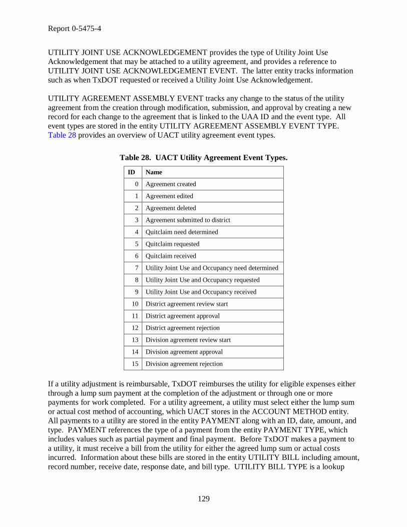
Report 0-5475-4
129
UTILITY JOINT USE ACKNOWLEDGEMENT provides the type of Utility Joint Use
Acknowledgement that may be attached to a utility agreement, and provides a reference to
UTILITY JOINT USE ACKNOWLEDGEMENT EVENT. The latter entity tracks information
such as when TxDOT requested or received a Utility Joint Use Acknowledgement.
UTILITY AGREEMENT ASSEMBLY EVENT tracks any change to the status of the utility
agreement from the creation through modification, submission, and approval by creating a new
record for each change to the agreement that is linked to the UAA ID and the event type. All
event types are stored in the entity UTILITY AGREEMENT ASSEMBLY EVENT TYPE.
Table 28 provides an overview of UACT utility agreement event types.
Table 28. UACT Utility Agreement Event Types.
ID Name
0 Agreement created
1 Agreement edited
2 Agreement deleted
3 Agreement submitted to district
4 Quitclaim need determined
5 Quitclaim requested
6 Quitclaim received
7 Utility Joint Use and Occupancy need determined
8 Utility Joint Use and Occupancy requested
9 Utility Joint Use and Occupancy received
10 District agreement review start
11 District agreement approval
12 District agreement rejection
13 Division agreement review start
14 Division agreement approval
15 Division agreement rejection
If a utility adjustment is reimbursable, TxDOT reimburses the utility for eligible expenses either
through a lump sum payment at the completion of the adjustment or through one or more
payments for work completed. For a utility agreement, a utility must select either the lump sum
or actual cost method of accounting, which UACT stores in the ACCOUNT METHOD entity.
All payments to a utility are stored in the entity PAYMENT along with an ID, date, amount, and
type. PAYMENT references the type of a payment from the entity PAYMENT TYPE, which
includes values such as partial payment and final payment. Before TxDOT makes a payment to
a utility, it must receive a bill from the utility for either the agreed lump sum or actual costs
incurred. Information about these bills are stored in the entity UTILITY BILL including amount,
record number, receive date, response date, and bill type. UTILITY BILL TYPE is a lookup

Report 0-5475-4
130
entity to specify the bill type, such as final bill (lump sum), incremental bill (actual cost), and
final bill (actual cost).
Table 29. Utility Agreement Assembly Subject Area Entities.
Name Definition
ACCOUNTING METHOD
An ACCOUNTING METHOD is a process to account for costs incurred during the adjustment of a utility facility, such as the category cost
approach or the unit cost approach.
COMPOSITE ELIGIBILITY RATIO
A COMPOSITE ELIGIBILITY RATIO is a percentage that describes the relative amount of multiple estimated utility adjustment cost that is eligible
for reimbursement by the state. A COMPOSITE ELIGIBILITY RATIO is
calculated by dividing the sum of the eligible costs of the adjustments by
the sum of the costs of the adjustments.
ELIGIBILITY RATIO An ELIGIBILITY RATIO is a percentage that describes the relative amount of an estimated utility adjustment cost that is eligible for
reimbursement by the state.
ELIGIBILITY RATIO
PROPERTY RIGHT
OCCUPANCY
An ELIGIBILITY RATIO PROPERTY RIGHT OCCUPANCY is an
association of an ELIGIBILITY RATIO with a PROPERTY RIGHT
OCCUPANCY. The purpose of this association entity is to resolve a
many-to-many relationship between the two entities.
ELIGIBILITY RATIO TYPE
An ELIGIBILITY RATIO TYPE is a category that describes a certain kind of ELIGIBILITY RATIO.
ESTIMATE An ESTIMATE is an approximation of costs for a utility adjustment that a utility provides to TxDOT that is part of a UTILITY AGREEMENT
ASSEMBLY in the form of an attachment.
ESTIMATE TYPE An ESTIMATE TYPE is a category that describes a certain kind of ESTIMATE.
MEASUREMENT UNIT A MEASUREMENT UNIT is an agreed upon standard for expressing distance.
PAYMENT A PAYMENT is a monetary compensation provided by TxDOT to a utility for the reimbursement of costs incurred during a utility adjustment.
PAYMENT TYPE A PAYMENT TYPE is a category that describes a certain kind of PAYMENT.
PRE QUALIFIED
CONTRACTOR
A PRE QUALIFIED CONTRACTOR is a utility contractor that is known
to the utility to be qualified to perform the work that is required by a utility
adjustment. All PRE QUALIFIED CONTRACTORs must be listed on
TxDOT’s form ROW-U-48 Statement Covering Utility Construction
Contract Work if the utility selects procedure B as the procedure to be used
in contracting work.
QUITCLAIM DEED A QUITCLAIM DEED is a type of deed that TxDOT receives from a property owner in which the property owner bargains, sells, releases, and
forever quitclaims his rights, title, interest, claim, and demand to a tract of
land. Source: TxDOT form ROW-N-30 Quitclaim Deed
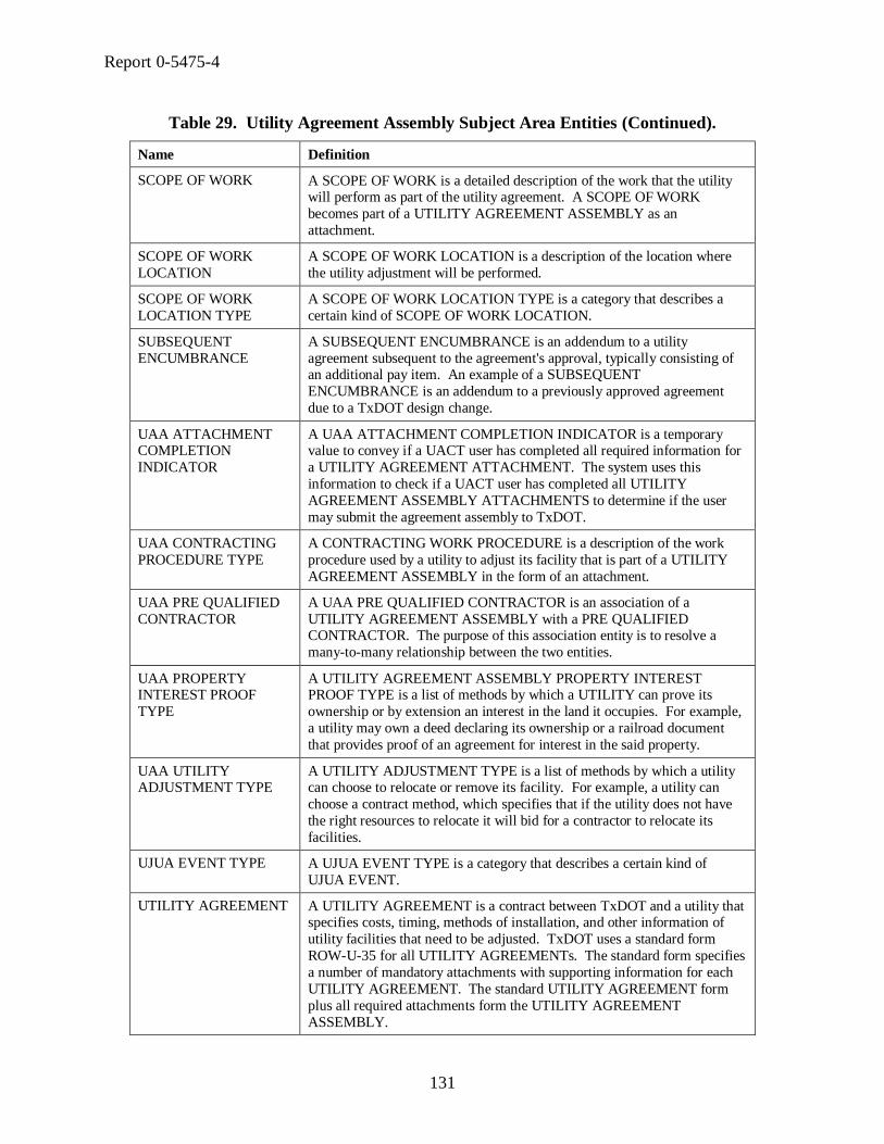
Report 0-5475-4
131
Table 29. Utility Agreement Assembly Subject Area Entities (Continued).
Name Definition
SCOPE OF WORK A SCOPE OF WORK is a detailed description of the work that the utility will perform as part of the utility agreement. A SCOPE OF WORK
becomes part of a UTILITY AGREEMENT ASSEMBLY as an
attachment.
SCOPE OF WORK
LOCATION
A SCOPE OF WORK LOCATION is a description of the location where
the utility adjustment will be performed.
SCOPE OF WORK
LOCATION TYPE
A SCOPE OF WORK LOCATION TYPE is a category that describes a
certain kind of SCOPE OF WORK LOCATION.
SUBSEQUENT
ENCUMBRANCE
A SUBSEQUENT ENCUMBRANCE is an addendum to a utility
agreement subsequent to the agreement's approval, typically consisting of an additional pay item. An example of a SUBSEQUENT
ENCUMBRANCE is an addendum to a previously approved agreement
due to a TxDOT design change.
UAA ATTACHMENT COMPLETION
INDICATOR
A UAA ATTACHMENT COMPLETION INDICATOR is a temporary value to convey if a UACT user has completed all required information for
a UTILITY AGREEMENT ATTACHMENT. The system uses this
information to check if a UACT user has completed all UTILITY
AGREEMENT ASSEMBLY ATTACHMENTS to determine if the user
may submit the agreement assembly to TxDOT.
UAA CONTRACTING
PROCEDURE TYPE
A CONTRACTING WORK PROCEDURE is a description of the work
procedure used by a utility to adjust its facility that is part of a UTILITY
AGREEMENT ASSEMBLY in the form of an attachment.
UAA PRE QUALIFIED
CONTRACTOR
A UAA PRE QUALIFIED CONTRACTOR is an association of a
UTILITY AGREEMENT ASSEMBLY with a PRE QUALIFIED CONTRACTOR. The purpose of this association entity is to resolve a
many-to-many relationship between the two entities.
UAA PROPERTY INTEREST PROOF
TYPE
A UTILITY AGREEMENT ASSEMBLY PROPERTY INTEREST PROOF TYPE is a list of methods by which a UTILITY can prove its
ownership or by extension an interest in the land it occupies. For example,
a utility may own a deed declaring its ownership or a railroad document
that provides proof of an agreement for interest in the said property.
UAA UTILITY ADJUSTMENT TYPE
A UTILITY ADJUSTMENT TYPE is a list of methods by which a utility can choose to relocate or remove its facility. For example, a utility can
choose a contract method, which specifies that if the utility does not have
the right resources to relocate it will bid for a contractor to relocate its
facilities.
UJUA EVENT TYPE A UJUA EVENT TYPE is a category that describes a certain kind of
UJUA EVENT.
UTILITY AGREEMENT A UTILITY AGREEMENT is a contract between TxDOT and a utility that specifies costs, timing, methods of installation, and other information of
utility facilities that need to be adjusted. TxDOT uses a standard form
ROW-U-35 for all UTILITY AGREEMENTs. The standard form specifies
a number of mandatory attachments with supporting information for each
UTILITY AGREEMENT. The standard UTILITY AGREEMENT form
plus all required attachments form the UTILITY AGREEMENT
ASSEMBLY.

Report 0-5475-4
132
Table 29. Utility Agreement Assembly Subject Area Entities (Continued).
Name Definition
UTILITY AGREEMENT ASSEMBLY
A UTILITY AGREEMENT ASSEMBLY is a document set that includes all documents that are needed for a UTILITY AGREEMENT between
TxDOT and other agencies in connection with a utility adjustment. A
UTILITY AGREEMENT ASSEMBLY consists of the UTILITY
AGREEMENT standard form ROW-U-35 and several attachments, such as
engineering estimate, proposed design drawing, and Utility Joint Use
Acknowledgement.
UTILITY AGREEMENT ASSEMBLY
ATTACHMENT
A UTILITY AGREEMENT ATTACHMENT is a document that is listed in TxDOT’s form ROW-U-35 (Standard Utility Agreement) as one of
several attachments that must be attached to form ROW-U-35 for the
agreement to become valid. A Utility Agreement Assembly consists of
form ROW-U-35 with all required attachments.
UTILITY AGREEMENT ASSEMBLY EVENT
A UTILITY AGREEMENT ASSEMBLY EVENT is the occurrence of a change to a UTILITY AGREEMENT ASSEMBLY.
UTILITY AGREEMENT ASSEMBLY EVENT
TYPE
A UTILITY AGREEMENT ASSEMBLY EVENT TYPE is a category that describes a certain kind of UTILITY AGREEMENT ASSEMBLY
EVENT.
UTILITY AGREEMENT
ASSEMBLY
REIMBURSEMENT
APPROACH
A REIMBURSEMENT APPROACH is one of three allowable processes
selected by a utility company to be reimbursed for costs incurred during the
adjustment of a utility facility. The utility’s selection is recorded in an
attachment that is part of a UTILITY AGREEMENT ASSEMBLY.
UTILITY AGREEMENT
ASSEMBLY SEQUENCE
A UTILITY AGREEMENT ASSEMBLY SEQUENCE is a number that
specifies the position where a UTILITY AGREEMENT ASSEMBLY ATTACHMENT appears in UACT in the list of attachments that need to
be completed to produce all required documents for a UTILITY
AGREEMENT ASSEMBLY. The purpose of this entity is to facilitate
changes to the order in which UTILITY AGREEMENT ASSEMBLY
ATTACHMENTS are presented to a system user.
UTILITY AGREEMENT ASSEMBLY UTILITY
CONFLICT
A UTILITY AGREEMENT ASSEMBLY UTILITY CONFLICT is an association of a UTILITY AGREEMENT ASSEMBLY with a UTILITY
CONFLICT. The purpose of this association entity is to resolve a many-to-
many relationship between the two entities.
UTILITY BILL A UTILITY BILL is a request for payment that a utility submits to
TxDOT.
UTILITY BILL TYPE A UTILITY BILL TYPE is a category that describes a certain kind of
UTILITY BILL.
UTILITY JOINT USE
ACKNOWLEDGEMENT
A UTILITY JOINT USE ACKNOWLEDGEMENT is an agreement
between TxDOT and a utility that sets forth the rights and obligations of
both parties for occupying, maintaining, accessing, and notifying changes by either party in their facilities. It establishes the relationship between a
utility and TxDOT where they will continue to occupy common right of
way after an adjustment. A UTILITY JOINT USE
ACKNOWLEDGEMENT is also used for the utility’s continued use of
existing easements and facilities within state right of way.
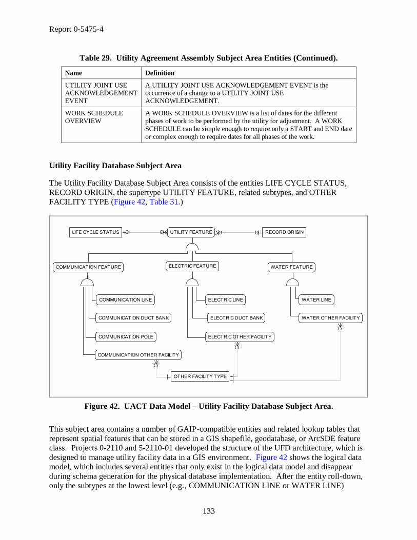
Report 0-5475-4
133
Table 29. Utility Agreement Assembly Subject Area Entities (Continued).
Name Definition
UTILITY JOINT USE ACKNOWLEDGEMENT
EVENT
A UTILITY JOINT USE ACKNOWLEDGEMENT EVENT is the occurrence of a change to a UTILITY JOINT USE
ACKNOWLEDGEMENT.
WORK SCHEDULE
OVERVIEW
A WORK SCHEDULE OVERVIEW is a list of dates for the different
phases of work to be performed by the utility for adjustment. A WORK
SCHEDULE can be simple enough to require only a START and END date
or complex enough to require dates for all phases of the work.
Utility Facility Database Subject Area
The Utility Facility Database Subject Area consists of the entities LIFE CYCLE STATUS,
RECORD ORIGIN, the supertype UTILITY FEATURE, related subtypes, and OTHER
FACILITY TYPE (Figure 42, Table 31.)
COMMUNICATION LINE WATER LINEELECTRIC LINE
COMMUNICATION POLE
ELECTRIC DUCT BANKCOMMUNICATION DUCT BANK
UTILITY FEATURE
COMMUNICATION FEATURE ELECTRIC FEATURE
LIFE CYCLE STATUS RECORD ORIGIN
COMMUNICATION OTHER FACILITY
OTHER FACILITY TYPE
ELECTRIC OTHER FACILITY
WATER OTHER FACILITY
WATER FEATURE
Figure 42. UACT Data Model – Utility Facility Database Subject Area.
This subject area contains a number of GAIP-compatible entities and related lookup tables that
represent spatial features that can be stored in a GIS shapefile, geodatabase, or ArcSDE feature
class. Projects 0-2110 and 5-2110-01 developed the structure of the UFD architecture, which is
designed to manage utility facility data in a GIS environment. Figure 42 shows the logical data
model, which includes several entities that only exist in the logical data model and disappear
during schema generation for the physical database implementation. After the entity roll-down,
only the subtypes at the lowest level (e.g., COMMUNICATION LINE or WATER LINE)
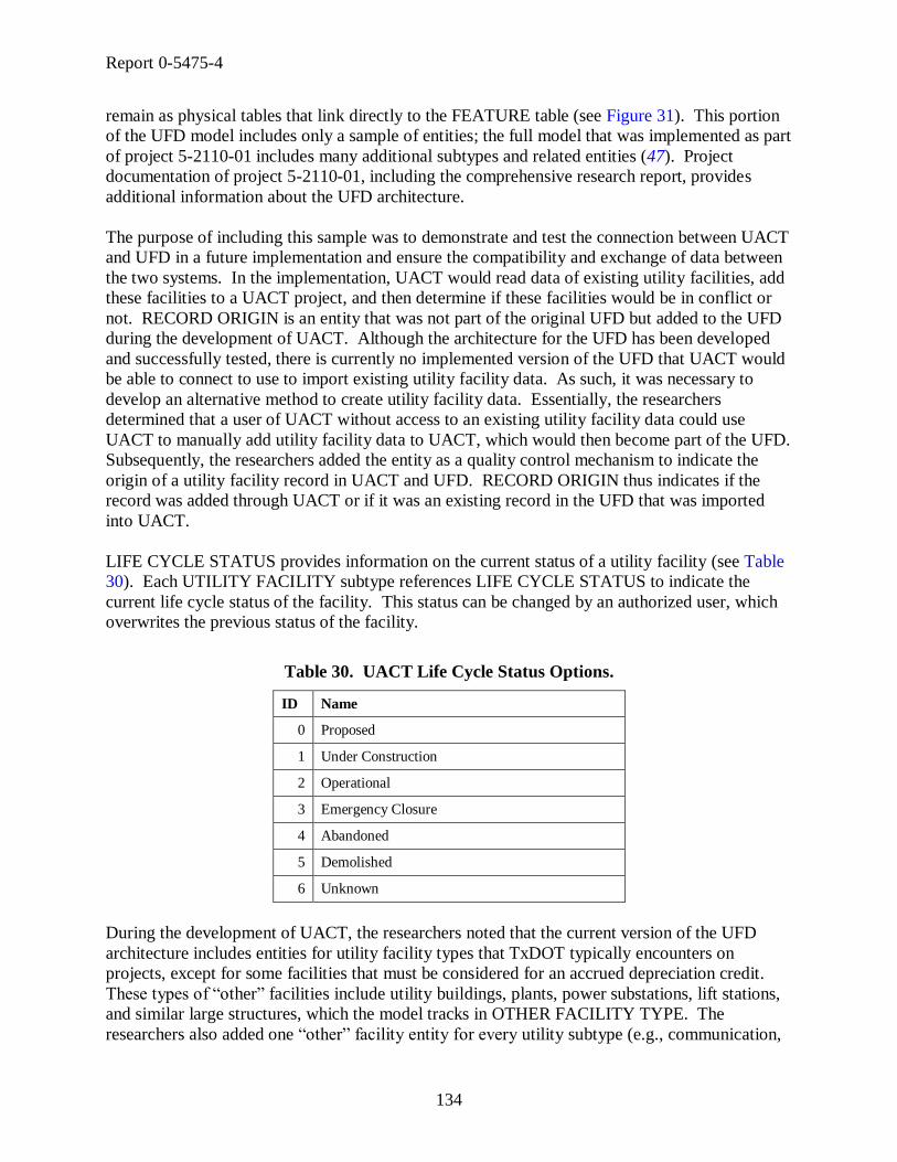
Report 0-5475-4
134
remain as physical tables that link directly to the FEATURE table (see Figure 31). This portion
of the UFD model includes only a sample of entities; the full model that was implemented as part
of project 5-2110-01 includes many additional subtypes and related entities (47). Project
documentation of project 5-2110-01, including the comprehensive research report, provides
additional information about the UFD architecture.
The purpose of including this sample was to demonstrate and test the connection between UACT
and UFD in a future implementation and ensure the compatibility and exchange of data between
the two systems. In the implementation, UACT would read data of existing utility facilities, add
these facilities to a UACT project, and then determine if these facilities would be in conflict or
not. RECORD ORIGIN is an entity that was not part of the original UFD but added to the UFD
during the development of UACT. Although the architecture for the UFD has been developed
and successfully tested, there is currently no implemented version of the UFD that UACT would
be able to connect to use to import existing utility facility data. As such, it was necessary to
develop an alternative method to create utility facility data. Essentially, the researchers
determined that a user of UACT without access to an existing utility facility data could use
UACT to manually add utility facility data to UACT, which would then become part of the UFD.
Subsequently, the researchers added the entity as a quality control mechanism to indicate the
origin of a utility facility record in UACT and UFD. RECORD ORIGIN thus indicates if the
record was added through UACT or if it was an existing record in the UFD that was imported
into UACT.
LIFE CYCLE STATUS provides information on the current status of a utility facility (see Table
30). Each UTILITY FACILITY subtype references LIFE CYCLE STATUS to indicate the
current life cycle status of the facility. This status can be changed by an authorized user, which
overwrites the previous status of the facility.
Table 30. UACT Life Cycle Status Options.
ID Name
0 Proposed
1 Under Construction
2 Operational
3 Emergency Closure
4 Abandoned
5 Demolished
6 Unknown
During the development of UACT, the researchers noted that the current version of the UFD
architecture includes entities for utility facility types that TxDOT typically encounters on
projects, except for some facilities that must be considered for an accrued depreciation credit.
These types of ―other‖ facilities include utility buildings, plants, power substations, lift stations,
and similar large structures, which the model tracks in OTHER FACILITY TYPE. The
researchers also added one ―other‖ facility entity for every utility subtype (e.g., communication,

Report 0-5475-4
135
electric, and water) such as COMMUNICATION OTHER FACILITY to track data important for
accrued depreciation calculations, such as actual service length, total life expectancy, and
original cost.
Table 31. Utility Facility Database Subject Area Entities.
Name Definition
COMMUNICATION DUCT BANK
A COMMUNICATION DUCT BANK is a linear structure that contains ducts that house underground communication lines.
COMMUNICATION FEATURE
A COMMUNICATION FEATURE is a UTILITY FEATURE that represents telecommunication utilities.
COMMUNICATION LINE
A COMMUNICATION LINE is a line that can carry data, voice (telephone), or video (including television) signals. Depending on the carrier technology
and other factors, communication lines can include optical fiber, coaxial
cable, or twisted pair copper.
COMMUNICATION OTHER FACILITY
A COMMUNICATION OTHER FACILITY is a COMMUNICATION FEATURE that does not fit into any of the COMMUNICATION FEATURE
subtypes provided. An example of a COMMUNICATION OTHER
FACILITY would be a large facility or building used to support
communication infrastructure.
COMMUNICATION
POLE
A COMMUNICATION POLE is a support structure for overhead
communication lines and/or equipment. For simplicity (and for consistency
with the naming convention for electric support structures), a pole is treated as a generic term that includes traditional poles, A-frame towers (sometimes
called A-frame poles), H-frame towers (sometimes called H-frame poles),
lattice towers, and tube towers (sometimes called tube poles).
ELECTRIC DUCT BANK
An ELECTRIC DUCT BANK is a linear structure that contains ducts that house underground electric lines.
ELECTRIC FEATURE An ELECTRIC FEATURE is a UTILITY FEATURE that represents electric utilities.
ELECTRIC LINE An ELECTRIC LINE is a line that carries electricity.
ELECTRIC OTHER FACILITY
An ELECTRIC OTHER FACILITY is an ELECTRIC FEATURE that does not fit into any of the ELECTRIC FEATURE subtypes provided. An
example of an ELECTRIC OTHER FACILITY would be a large facility or
building used to support electric infrastructure.
LIFE CYCLE STATUS A LIFE CYCLE STATUS is an entity that describes the current life cycle
state of a utility facility. Examples include ―proposed,‖ ―under construction,‖
and ―operational.‖
OTHER FACILITY
TYPE
An OTHER FACILITY TYPE is a category that describes a certain kind of
OTHER FACILITY, such as the type of a COMMUNICATION OTHER
FACILITY or a WATER OTHER FACILITY.
RECORD ORIGIN A RECORD ORIGIN is an entity that describes the origin of a record in the UACT utility inventory tables. Valid values are either ―Import from utility
inventory‖ or ―Added through UACT.‖

Report 0-5475-4
136
Table 31. Utility Facility Database Subject Area Entities (Continued).
Name Definition
UTILITY FEATURE A UTILITY FEATURE is a real-world or virtual phenomenon of a utility facility associated with a model that exists in a spatial or spatiotemporal
domain modeled consistent with the TxDOT GAIP standards and can be
surveyable. Examples include communication feature, electric feature, and
water line.
WATER FEATURE A WATER FEATURE is a UTILITY FEATURE that represents water
utilities.
WATER LINE A WATER LINE is a pipe that carries drinkable water.
WATER OTHER
FACILITY
A WATER OTHER FACILITY is a WATER FEATURE that does not fit
into any of the WATER FEATURE subtypes provided. An example of a WATER OTHER FACILITY would be a large facility or building used to
support water infrastructure.
Utility Installation Review Subject Area
The Utility Installation Review Subject Area consists of the main entities DOT UNIT, DOT
OFFICE, DOT USER, COMPANY, COMPANY OFFICE, COMPANY USER, SYSTEM
USER, OTHER UIR table, related lookup tables, and mapping tables that provide a link to other
subject areas (Figure 43, Table 32.)
COMPANY USER
COMPANY OFFICE
SYSTEM USER
DOT USER
DOT OFFICE
DOT UNIT TYPE
USER PLACE
PLACE TYPE
OFFICE PLACE
PLACE
DOT OFFICE TYPE
OFFICE
DOT UNIT
STATUS
STATE
COMPANY USER PROFILE
DOT USER PROFILE
PERMIT
PERMIT EVENT
PRIVILEGE
COMPANY
PERMIT EVENT LOCATION
Figure 43. UACT Data Model – Utility Installation Review Subject Area.

Report 0-5475-4
137
UACT is designed to share a common user system with UIR, which includes the sharing of
usernames, user profiles, company offices, and TxDOT offices between the two applications. As
such, users would log in to both systems with the same username and password and view the
same profile and contact information. UIR originally allowed for the storage of only utility
companies in its model. In UACT, this has been expanded to include other types of companies,
such as design consultants, SUE providers, and surveyors. The system determines the company
type by the ROLE that is mapped to the company in the COMPANY ROLE entity (See User
Subject Area and Permissions Subject Area for more information). For example, a company
may perform project design, roadway construction, and surveying. A utility company would
typically have only the ROLE utility ownership.
TxDOT offices are shared between the two applications. A TXDOT OFFICE record is created
for each individual office, with a TXDOT UNIT marking the administrative unit of the office. A
TXDOT UNIT TYPE is assigned to each TXDOT UNIT, determining if the TXDOT UNIT is at
the district or division level. For example, a TXDOT OFFICE could be ―Utility Permit Review
Office,‖ the TXDOT UNIT could be ―San Antonio,‖ and the TXDOT UNIT TYPE could be
―District.‖
The UACT data model allows the direct connection with the UIR system, including the user
management. All tables in the Utility Installation Review Subject Area are a part of the UIR
system and were included in the UACT data model to demonstrate connections between the two
systems. Implementing the UACT system may require some changes to existing UIR and/or
UACT entities.
In the model, a SYSTEM USER can be a company, an agency, or an individual. The primary
key for the SYSTEM USER entity is SYSTEM USER ID. This unique key identifies all users
that are included in the model regardless of type. The SYSTEM USER entity also links to the
DOCUMENT, MEETING, UTILITY CONFLICT, PERMISSION, PROJECT, USER, and
UTILITY AGREEMENT ASSEMBLY subject areas.
The data model uses the SYSTEM USER entity to reference the user in several entities. For
example, DOCUMENT VERSION tracks the user that created a new version of a document,
UTILITY CONFLICT EVENT tracks the user that made a change to a utility conflict, and
MEETING tracks the user that created a meeting within UACT.
Detailed user profile data are stored in DOT USER PROFILE and COMPANY USER PROFILE.
For TxDOT users and company users, the model also includes entities to handle office and unit
data, such as DOT UNIT, COMPANY OFFICE, OFFICE PLACE, and PLACE TYPE.

Report 0-5475-4
138
Table 32. Utility Installation Review Subject Area Entities.
Name Definition
COMPANY A COMPANY is any organization typically external to TxDOT that performs one or more ROLES for a PROJECT. This definition has been extended to
apply to any kind of company, not just utility companies as was originally
intended in the UIR application. In addition, a TxDOT office can be a
COMPANY for the purpose of managing TxDOT-owned utilities.
COMPANY OFFICE A COMPANY OFFICE is an organizational subdivision of a COMPANY.
An example of a COMPANY OFFICE is a local office of a statewide
operating COMPANY.
COMPANY USER A COMPANY USER is an installation owner employee who has a user account with the UIR and/or UACT system. A COMPANY USER may have
the authority to serve as an agent or representative for an installation owner in
the processes of creating, modifying, and submitting a request for a utility
installation permit.
COMPANY USER PROFILE
A COMPANY USER PROFILE is the detailed profile information, such as login information and contact information, of a COMPANY USER.
DOT OFFICE A DOT OFFICE is an administrative unit within TxDOT that has a specific responsibility in the utility permit workflow in the UIR system. Note that a
TXDOT OFFICE in the UIR system may not necessarily represent a physical
office that exists in TxDOT. For example, the "HOU Closed Requests"
represents a TXDOT OFFICE in the UIR system where the closed requests in
the Houston district are sent.
DOT OFFICE TYPE A DOT OFFICE TYPE is a category of DOT OFFICE that defines its role in
a state DOT's business processes.
DOT UNIT A DOT UNIT is an organizational sub-element of TxDOT and includes the 25 geographical areas within the State of Texas designated as districts and all
TxDOT divisions.
DOT UNIT TYPE A DOT UNIT TYPE is an organization category for a DOT UNIT. Examples for DOT UNIT TYPE are TxDOT District and TxDOT Division.
DOT USER A DOT USER is a DOT employee who is registered with the UIR system. There are two types of DOT users in the UIR system in terms of user
function. The users from TxDOT districts may be granted with the authority
to serve as an agent or representative for TXDOT in the review and approval
of utility installation permits. On the other hand, the security administrators
in TxDOT districts and Maintenance Division, and the users from TxDOT
Information Systems Division and Right of Way Division, are included in the
UIR system for system monitoring and user management purposes. These
users are generally not involved in the utility installation permitting process.
DOT USER PROFILE A DOT USER PROFILE is the detailed profile information, such as login
information and contact information, of a DOT USER.
OFFICE An OFFICE is an administrative unit within TxDOT or a COMPANY that has a specific responsibility in the Project Development Process.
OFFICE PLACE An OFFICE PLACE is a one-to-one association between an OFFICE and a PLACE. This entity is included as a linkage between the OFFICE entity and
the PLACE entity.

Report 0-5475-4
139
Table 32. Utility Installation Review Subject Area Entities (Continued).
Name Definition
PERMIT A PERMIT is a transaction that authorizes a utility company to install non-reimbursable utilities on the state right of way. At TxDOT, the permitting
process includes submitting an installation request (also known as notice of
proposed installation (NOPI), the review process, approval and pre-
construction, construction, and post-construction and archival. UIR generates
a record for a permit in the PERMIT table when a utility company user moves
from Step 1 to Step 2 while preparing an installation request.
PERMIT EVENT A PERMIT EVENT is a transaction in the life of a permit. Every activity associated with a permit will initiate an EVENT in the database that describes
that activity.
PERMIT EVENT LOCATION
A PERMIT EVENT LOCATION is the utility installation location that is described in an installation permit request when it is either originally
submitted or submitted as a revised or amended request. The UIR system
creates a record of the PERMIT EVENT LOCATION for the following three
types of PERMIT EVENT: submitting a PERMIT request, submitting a
revised PERMIT request, and submitting an amendment PERMIT request.
PLACE A PLACE is a postal address consisting of a street address, city, state, and
ZIP code.
PLACE TYPE A PLACE TYPE is a category that describes a certain kind of PLACE.
Examples for PLACE TYPE include ―mailing address,‖ ―physical address,‖
and ―both.‖
PRIVILEGE A PRIVILEGE is the level of access that a user has to the available functions
within the UIR and/or UACT system. Depending on the user type (i.e., TxDOT or installation owner), a user may be granted with one of the
following privilege levels: Guest, Consultant, User, Super User,
Administrator, and System Administrator.
STATE A STATE is a political division within the United States.
STATUS A STATUS is the status of a UIR user account. The UIR system allows a user account to have one of the following statuses: Active, Out of Office,
Pending, Rejected, Permanently Inactive, and Inactive.
SYSTEM USER A SYSTEM USER is a person that has an account and the authority to use the UIR and/or UACT system. The system allows two types of users: DOT
USERs and COMPANY USERs (e.g., installation owners). Both types of
SYSTEM USERs are assigned with different levels of system access for both
permitting and user management within the system.
USER PLACE A USER PLACE is a temporary one-to-one linkage between a USER and a
PLACE. A USER PLACE is created at the moment when the user account is
being created and it is then deleted from the database when the user account
is successfully created.

Report 0-5475-4
140
User Subject Area
The User Subject Area consists of the entities USER EVENT, USER EVENT TYPE, and the
mapping tables SYSTEM USER ROLE, COMPANY ROLE, and PROJECT COMPANY
(Figure 44, Table 33.)
USER EVENT
USER EVENT TYPE
PROJECT COMPANY
COMPANY ROLE
SYSTEM USER ROLE
Figure 44. UACT Data Model – User Subject Area.
USER EVENT references the SYSTEM USER ID and tracks changes to UACT users including
the day and time when the change occurred. A USER EVENT references a USER EVENT
TYPE, which can have the value ―creation,‖ ―modification,‖ or ―deletion.‖
SYSTEM USER ROLE is a mapping table that links a SYSTEM USER to a ROLE. The
mapping table allows a many-to-many relationship between SYSTEM USER and ROLE so that
a ROLE can be performed by many SYSTEM USERS and a SYSTEM USER can have many
different roles. The Permissions Subject Area provides more information about the use of roles
in UACT.
Similarly to SYSTEM USER ROLE, COMPANY ROLE is a mapping table that links a
COMPANY to a ROLE, allowing a many-to-many relationship between the two entities.
PROJECT COMPANY is the third mapping table in this subject area that links a PROJECT to a
COMPANY and vice versa.

Report 0-5475-4
141
Table 33. User Subject Area Entities.
Name Definition
COMPANY ROLE A COMPANY ROLE is a mapping between a COMPANY and a ROLE that describes one or more ROLEs that a COMPANY performs in the TxDOT
Project Development Process.
PROJECT COMPANY A PROJECT COMPANY is a mapping between PROJECT and COMPANY,
describing a COMPANY that is part of a PROJECT.
SYSTEM USER ROLE A SYSTEM USER ROLE is a specification of the ROLE that a SYSTEM
USER has. In other words, it is a mapping of ROLE and SYSTEM USER to
identify the ROLE of a user in UACT.
USER EVENT A USER EVENT is a creation or modification of a SYSTEM USER.
USER EVENT TYPE A USER EVENT TYPE is a category that describes a certain kind of a USER
EVENT transaction.
Utility Conflict Subject Area
The Utility Conflict Subject Area consists of the main entities UTILITY CONFLICT, UTILITY
CONFLICT EVENT, UTILITY CONFLICT RESOLUTION STRATEGY, UTILITY
CONFLICT FEATURE STATUS, NOTE, related lookup tables, and mapping tables that provide
a link to other subject areas (Figure 45, Table 38.)
UTILITY CONFLICT
NOTE
UTILITY CONFLICT EVENT TYPE
DOCUMENT VERSION NOTE
UTILITY CONFLICT EVENT NOTE
UTILITY CONFLICT TYPE
UTILITY CONFLICT FEATURE STATUS
UTILITY CONFLICT RESOLUTION STRATEGY
UTILITY CONFLICT RESOLUTION STRATEGY SET
UTILITY CONFLICT EVENT FEATURE
UTILITY CONFLICT EVENT
UAR EXCEPTION UAR EXCEPTION TYPEUTILITY CONFLICT LEGAL STATUS
UTILITY CONFLICT ADJUSTMENT COST
Figure 45. UACT Data Model – Utility Conflict Subject Area.
The purpose of this subject area is to track utility conflicts and associated data. Within UACT,
utility conflict data is primarily distributed among three main entities, which are UTILITY
CONFLICT, UTILITY CONFLICT EVENT, and UTILITY CONFLICT OUTLINE. The latter
entity stores all attributes describing references to the shape and location of a conflict. For more
information about UTILITY CONFLICT OUTLINE, refer to the ArcSDE Subject Area.

Report 0-5475-4
142
Utility conflicts are created in the UTILITY CONFLICT entity that provides an ID, references
UTILITY CONFLICT TYPE, links the conflict to a UACT project, provides a time and date for
the record creation, and stores estimated dates for start and completion of the conflict adjustment,
if available. UACT tracks four different types of utility conflicts shown in Table 34.
Table 34. UACT Utility Conflict Types.
ID Name
0 Conflict with roadway project features.
1 Conflict with another utility feature.
2 Conflict with utility regulations or standards.
3 Conflict with safety regulations.
Every change to a utility conflict is stored in UTILITY CONFLICT EVENT along with the date
and time of the change. This entity references the UTILITY CONFLICT ID, so that a new
record is created for each new event to a utility conflict. Other attributes are UTILITY
CONFLICT DESCRIPTION, and UTILITY CONFLICT EVENT LEGAL DATE. The latter
attribute tracks the date when a user makes a change to a UTILITY CONFLICT LEGAL
STATUS, which determines the current legal status of the utility conflict. Currently, UACT
tracks the following types of utility conflict statuses (Table 35).
Table 35. UACT Utility Conflict Legal Status Types.
ID Name
0 Pending plans sufficient
1 Plans sufficient submitted
2 30-day notice submitted
3 90-day notice submitted
UTILITY CONFLICT EVENT FEATURE is a mapping table that links a UTILITY CONFLICT
EVENT to a FEATURE. UACT uses this table to identify the features that are part of a conflict.
This structure allows a feature, e.g., an electric line, to be part of many conflicts, and also allows
one conflict to include many features. However, testing of preliminary versions of UACT found
that the management of utility agreements becomes significantly more difficult if utilities can be
part of multiple conflicts, or if a conflict can consist of multiple utilities. Following a
recommendation of the panel, the researchers limited the association of a utility facility to only
one conflict through code.
The structure of UTILITY CONFLICT EVENT FEATURE allows a tracking of all feature
changes to the utility conflict. UTILITY CONFLICT FEATURE STATUS provides the current
status of a feature and can have the following values (Table 36).

Report 0-5475-4
143
Table 36. UACT Utility Conflict Feature Status Types.
ID Name
0 Not yet reviewed
1 Possible conflict
2 Confirmed conflict
3 Resolved conflict
UTILITY CONFLICT EVENT also links to UTILITY CONFLICT OUTLINE directly (see
ArcSDE Subject Area). This link allows the association of a UTILITY CONFLICT OUTLINE
feature with a utility conflict.
UAR EXCEPTION tracks if a utility conflict is subject to an exception to the UAR, along with
amount, dates, comments, and indication of approval. The category of the exception is tracked
in UAR EXCEPTION TYPE.
UTILITY CONFLICT RESOLUTION STRATEGY tracks the current strategy that was selected
to resolve a utility conflict. UTILITY CONFLICT RESOLUTION STRATEGY SET allows the
linking of multiple utility conflict resolution strategies with a utility conflict. This entity also
includes flags to indicate the recommended resolution strategy and an indicator of the strategy
that was ultimately used. Table 37 shows the valid values for a UTILITY CONFLICT
RESOLUTION STRATEGY.
Table 37. UACT Utility Conflict Resolution Strategy Types.
ID Name
0 Adjustment
1 Abandon in-place
2 Exception
3 Design change
Table 38. Utility Conflict Subject Area Entities.
Name Definition
DOCUMENT VERSION NOTE
A DOCUMENT VERSION NOTE is a mapping between a NOTE and a DOCUMENT VERSION allowing a SYSTEM USER to provide
miscellaneous information about a DOCUMENT VERSION.
NOTE A NOTE is miscellaneous information that provides extra detail or
description for an event.
UAR EXCEPTION A UAR EXCEPTION is the exemption of a utility of the rules and regulations
set forth in the Texas Utility Accommodation Rules codified in Texas
Administrative Code 43 Chapter 21.31 to 21.56.

Report 0-5475-4
144
Table 38. Utility Conflict Subject Area Entities (Continued).
Name Definition
UAR EXCEPTION TYPE
A UAR EXCEPTION TYPE is a category that describes a certain kind of UAR EXCEPTION.
UTILITY CONFLICT A UTILITY CONFLICT is an instance where a utility facility is non-
compliant with the TxDOT Utility Accommodation Rules, is non-compliant
with safety regulations, is located within the extent of a proposed roadway
improvement design of a TxDOT PROJECT, or is located within the extent of
a proposed utility facility. A UTILITY CONFLICT can be resolved by
modifying the proposed roadway improvement design, adjusting/relocating the utility facility, or granting an exception/making changes to the current
Utility Accommodation Rules or safety regulations.
UTILITY CONFLICT ADJUSTMENT COST
A UTILITY CONFLICT ADJUSTMENT COST is the amount that a utility owner estimates to expend on the removal of a utility conflict by adjusting the
utility facility.
UTILITY CONFLICT EVENT
A UTILITY CONFLICT EVENT is the occurrence of a change to a UTILITY CONFLICT.
UTILITY CONFLICT EVENT FEATURE
A UTILITY CONFLICT EVENT FEATURE is a collection of features involved with a given UTILITY CONFLICT EVENT.
UTILITY CONFLICT EVENT NOTE
A UTILITY CONFLICT EVENT NOTE is a mapping between a NOTE and a UTILITY CONFLICT EVENT allowing a SYSTEM USER to provide
miscellaneous information about a UTILITY CONFLICT.
UTILITY CONFLICT
EVENT TYPE
A UTILITY CONFLICT EVENT TYPE is a category that describes a certain
kind of UTILITY CONFLICT EVENT.
UTILITY CONFLICT
FEATURE STATUS
A UTILITY CONFLICT FEATURE STATUS is a mapping from a UTILITY
CONFLICT STATUS CODE to a step in the process of solving a utility
conflict.
UTILITY CONFLICT LEGAL STATUS
A UTILITY CONFLICT LEGAL STATUS is an indication of how much progress has been made in resolving a conflict. It can be at a status of ―Plans
sufficient submitted,‖ which means that the utility has been provided with
plans for the project, which would allow it to adjust its facility and in turn
resolve a conflict. A status of ―30-day notice submitted‖ indicates that it has
been 30 days since project plans were submitted but no action was taken.
Similarly, a status of ―90-day notice submitted‖ indicates that it has been 90
days since the submission of project plans with no action from the utility.
UTILITY CONFLICT
RESOLUTION
STRATEGY
A UTILITY CONFLICT RESOLUTION STRATEGY is an option to resolve
a utility conflict. Examples include ―Design Change,‖ ―Utility Adjustment,‖
and ―UAR exception.‖
UTILITY CONFLICT
RESOLUTION
STRATEGY SET
A UTILITY CONFLICT RESOLUTION STRATEGY SET is a set of
proposed options for solving a particular conflict.
UTILITY CONFLICT TYPE
A UTILITY CONFLICT TYPE is the immediate cause of a CONFLICT.
Report 0-5475-4
145
PHYSICAL DATA MODEL DEVELOPMENT
The research team developed a physical data model for the UACT system based on the logical
data model and following the TxDOT data architectures standards (51). In particular, the
physical model:
displays tables, columns, and foreign key constraint names;
matches corresponding data objects in the logical data model;
uses Information Engineering notation; and
identifies primary, foreign, and alternative keys.
The researchers added the foreign key constraints according to the following syntax:
FK_<Child Table Physical Name>_REF_<Parent Table Physical Name>
The researchers used up to 30 characters for the foreign key constraint. In cases where the
foreign key constraint would have been longer than 30 characters using the full table names, the
researchers abbreviated table names as needed.
The physical data model was created for an implementation using Oracle 10g and uses four
separate tablespaces:
UACT. This tablespace includes the tables of the subject areas Feature, Utility Conflict,
Utility Agreement Assembly, Permissions, Project, Document, Meeting, User, and
System.
DCIS. This tablespace includes the DCIS Subject Area table.
UFD. This tablespace includes the tables of the Utility Facility Database Subject Area.
SDE. This tablespace includes the tables of the ArcSDE Subject Area.
During development, the research team created two copies of the UACT tablespace to test
changes to the prototype while keeping one version ready for user testing at all times. During
implementation, the research team would likely keep these copies for testing and development of
modifications to the prototype. The researchers also created the following Oracle tablespaces to
test connections to existing systems:
FileNet. This tablespace includes the tables of the FileNet Subject Area.
MainStreet. This tablespace includes the tables of the MainStreet Texas Subject Area.
ROWIS. This tablespace includes the tables of the ROWIS Subject Area.
UIR. This tablespace includes the tables of the UIR Subject Area.

Report 0-5475-4
146
In an implementation, these tablespaces would not need to be created but would be replaced by
existing systems. The tables of the subtype GAIP Feature, including Asset Features and
Geopolitical Features, were implemented as ESRI ArcSDE tables in the Oracle table space.
DATA DICTIONARY
The research team developed a data dictionary of the logical data model entities and attributes,
including complete entity and attribute definitions, and attribute purpose, examples, valid values,
format, and datatype. The research team submitted the data dictionary as part of product P2.

Report 0-5475-1
147
CHAPTER 6. UTILITY ACCOMMODATION AND CONFLICT
TRACKER PROTOTYPE
INTRODUCTION
UACT is a web-based prototype for the management and tracking of utility conflicts. Key
functionalities of UACT include:
Utility Conflict Tracking. DOT officials can enter utility conflict data based on existing
utility facility data and create visual representations of utility conflicts using a mapping
component. The prototype also provides an overview of the status of utility conflicts for
each project.
Utility Agreement Development and Tracking. A utility company can complete the
required forms of a utility agreement online and file the document electronically for
review by the appropriate district and division personnel. The system guides the user
through the completion process and selects appropriate forms based on the specific
circumstances of the utility conflict.
Document Upload and Conversion to PDF. The prototype allows users to upload
documents that are accessible to other users based on roles and privileges. The prototype
converts all documents automatically to PDF to allow easy access to all privileged users.
DCIS Project Data Access. The researchers designed the prototype to connect to DCIS
and display project data that are collected in a DCIS data warehouse.
UFD Access. The researchers designed the prototype to integrate with a GIS-based
database of utility facility features.
User Access Model. UACT provides a comprehensive and flexible access system based
on capabilities, roles, and privileges. UACT administrators can further customize access
to UACT by providing individual users access to specific projects.
The web-based nature of the application facilitates access by TxDOT users as well as a wide
range of external consultants, contractors, and utility companies. TxDOT users can manage
projects, utilities, conflicts, meetings, and contacts. External users can perform tasks relevant to
the role they play in the highway project. This UACT version highlights the majority of features
that the UACT data model supports, including GIS visualization and a user permissions system
that is linked to the existing account system in UIR.
UACT SYSTEM ARCHITECTURE
UACT provides access to data related to utility coordination activities that are collected on a
database server and provided to users using a web server. Figure 46 provides a general overview
of the UACT system architecture.

Report 0-5475-4
148
Figure 46. UACT System Architecture Diagram.
UACT is a system that consists of several components that researchers designed to manage
utility conflict data using web-based access. As Figure 47 shows, UACT has two main groups of
components: client-side components and server-side components. On the client side, a web
browser serves as a front-end interface that allows users on client computers to interact with the
UACT system to complete the utility adjustment process. Both utility company users and
TxDOT users can act as clients, but their interfaces are different and have different access levels.
To access UACT, users must have a computer that meets the following minimum system
requirements:
desktop or laptop computer running Windows XP with Service Pack 2 (SP2),
Microsoft Internet Explorer® 6.0 with SP2 or higher,
PDF reader such as Adobe® Acrobat Reader
® 7.0,
internet connection,
e-mail account, and
UACT active account.

Report 0-5475-4
149
.NET Framework 2.0
Virtual
Folders
File System
Object(FSO)
File Upload
Component
Oracle
Map Server(ArcGIS
Server)
Secondary Storage
Microsoft Internet Information Services(IIS)
Spatial Data
Engine(ArcSDE)
Web Browser
Server Side
Client Side
Generator (AdLib Express
Server)
Oracle
Client
Web Server
Oracle Server
Client
Figure 47. UACT System Architecture.
On the server side, UACT includes a number of system components, including the following:
Web server. Microsoft Internet Information Services® (IIS) 6.0 running on Windows
Server 2003.
Map server. ESRI ArcGIS Server Version 9.2.

Report 0-5475-4
150
Spatial data engine. ArcGIS Server can be configured to access spatial data in formats
such as ESRI shape file format, personal geodatabases (.mdb file format), or
geodatabases using ESRI ArcSDE.
File upload component. UACT currently uses a file upload component of .NET.
UACT could use another upload component such as SoftArtisans®
FileUp™.
PDF generator. Adlib Software Adlib Express Server with Compressor Add-On. This
standalone server application monitors the contents of a specific input folder at regular
time intervals. In UACT, the application checks the contents of a designated input folder
every five seconds. If Adlib Express Server detects a new file in that folder (typically if a
utility company or TxDOT user has uploaded a file to the server), Adlib Express Server
generates a PDF file and stores that file in a designated output folder. In order for Adlib
Express Server to convert a file to PDF, an application that can open the file must be
installed on the server.
Microsoft Office (Word®
, Excel, PowerPoint®, and Visio
®). Adlib Express Server
supports a number of native applications installed on the server, including Microsoft
Office. UACT recognizes Word, Excel, PowerPoint, and Visio files, allowing Adlib
Express Server to generate PDF versions of Word (.doc) files, Excel (.xls) files,
PowerPoint (.ppt) files, and Visio (.vsd) files.
Additional PDF file generation support. Cimmetry AutoVue 2D Desktop (now
Oracle® AutoVue) enables Adlib Express Server to generate PDF versions of additional
file types, in particular MicroStation® (.dgn) and AutoCAD
® (.dwg).
Microsoft .NET™ 2.0 framework. An integral Windows component required to run
applications developed with .NET technology. The version used for the implementation
of UACT is 2.0.
Oracle Client. In order for the IIS web server to communicate with the Oracle database
server and retrieve data, it requires a data provider that supports Oracle. UACT uses
the .NET Managed Provider for Oracle from Microsoft, which is part of the .NET 2.0
framework.
As Figure 47 shows, the UACT implementation uses two server side environments: a database
server (that includes Oracle and ArcSDE) and a web server (that includes all other components
in addition to the UACT code). The web server also stores all files uploaded to the system as
well as data files UACT generates during the utility adjustment process. A UACT
implementation at TxDOT will likely involve separate mapping and data storage servers. In
addition, TxDOT would connect UACT to an existing email server to allow for system-generated
email notifications.
UACT uses ESRI ArcGIS Server located on the web server to serve maps of utility conflict
locations to system users. ArcGIS Server connects to ArcSDE on the Oracle server, which is
ESRI’s Spatial Data Engine that spatially enables a portion of the data in the Oracle server. This
Report 0-5475-4
151
architecture represents an integrated environment that allows access to a comprehensive database
of spatial data accessible to multiple users, as compared to the traditional approach of managing
geographic data on separate local drives.
Permissions System
Experience with the implementation of the UIR system has shown that maintaining a strict
workflow-control system for the specific tasks supported by UACT would result in an unfeasible
level of administrative overhead. Instead, the researchers designed a permissions-based system
that allows any user to make changes at any time that are within his or her level of access. The
UACT permissions model provides highly detailed user access levels, mapping of companies,
functions in the Project Development Process, and user groups that the system combines to a
user-specific set of application capabilities.
Utility Conflict List
The core of the interface, the utility conflict list, mimics the current business processes of public
and private utility coordination staff while providing a robust and more widely accessible user
experience. The researchers expect that the use of the familiar paradigm of conflict list will
reduce training costs and allow both internal and external offices to TxDOT to implement the
system quickly. The team designed UACT as a drop-in replacement for the current district,
company, and in some cases, user-specific systems such as custom Microsoft Access databases
and Microsoft Excel spreadsheets. In districts where the UIR system has already been deployed,
implementation costs will be further reduced due to the sharing of system resources. Training
costs will be reduced by common system layout and a shared user login system between the two
applications.
PROTOTYPE FUNCTIONALITY
This section provides a general overview of the functionality of the UACT beta version. For a
complete description of the system functionality, refer to deliverable 0-5475-R3, the UACT user
guide.
The UACT system can be accessed using a standard Internet browser. Users can access the main
sections of the application by clicking on one of the links of the main navigation area provided at
the top of each page of the application, as follows:
Home. This is the start page that lists all active projects within UACT.
Project. A section that gives an overview of the selected project’s information.
Utility Inventory. This section provides an overview of utility facilities associated with
the currently selected project as well as the capability to add or import new utility
facilities.

Report 0-5475-4
152
Conflict Tracking. This section provides an overview of the currently selected project’s
utility conflicts.
Agreement Assembly. This section provides a mechanism to complete a utility
agreement assembly with the help of a sequence of steps, create new agreements, and edit
existing utility agreement assemblies.
Reporting. This section provides a tool to create customized reports using data stored in
UACT.
Contacts. This section provides a link to the project contact database that UACT shares
with the UIR system.
Other Resources. This section provides resources to the users of UACT that are related
to utility coordination and accommodation, such as documents, policies, and guidelines.
Administration. This section provides a UACT system administrator with the ability to
control user access to UACT, create new users, and manage existing users and their
profiles.
All UACT screens display the currently logged-in user name in the top right corner. Similarly,
all screens allow the user to return to the project summary screen by clicking on the ―Home‖ link
in the top left corner. Users can log out of the application at any time on any screen by clicking
on the ―Logout‖ link on the top right corner next to the user name. The sections described above
essentially represent business areas or business area sections that UACT uses to restrict access to
areas of the system. For more information on access, business areas, and permissions, refer to
the Permissions Subject Area discussion in Chapter 5. The following is a brief overview of the
functionality of UACT in each business area.
Project Business Area
The project summary screen provides details to all stakeholders involved in a project (Figure 48).
Currently, the data that is displayed on the project summary screen is stored within the UACT
system. Optionally, depending on implementation, UACT could link directly to either ROWIS
or DCIS in an implementation version of the system.

Report 0-5475-4
153
Figure 48. Project Listing.
Currently, a UACT project combines data elements from DCIS and ROWIS. In order to track
utility conflicts and agreement assemblies, a user must associate utility facilities with the project
or create new utility facilities. Users with appropriate access to this section can import utility
facilities from the Utility Facility Database, which UACT automatically associates with the
current project.
There are several different stakeholders with different roles in a highway project, including
subcontractors and/or consulting companies employed by a utility company for a facility
adjustment, that may need access to project data throughout the project development process.
UACT allows the association of these stakeholders with a project using the stakeholder page.
Project documentation includes design schematics, construction plans, memorandums, bills, etc.
To facilitate the sharing of project data relevant to process stakeholders, UACT provides an
interface to upload documents in several business areas. Project files can be uploaded under the
project business area, and users with sufficient permissions (including stakeholders and third
parties as permitted) may view these documents. Documents in UACT can have several
revisions that UACT manages using a version control system that is part of the document upload
interface. Different versions of the same document can be uploaded when the user selects the
―detailed view‖ of a document. The interface then changes to show a document summary and all
other versions of the current document. If a user uploads a new document in the ―detailed view‖
of an existing document, UACT automatically creates a new version of the existing document.

Report 0-5475-4
154
Utility Inventory Business Area
The Utility Inventory Business Area shows a listing of all utility facilities within the project
limits that system users have entered into UACT (Figure 49). Utility facilities can also be
imported from an external database of utility facilities. A drop-down list allows the user to filter
the list of available utility facilities by facility type.
Figure 49. Utility Inventory Screen.
In UACT, conflicts (and by extension, utility agreement assemblies) require the existence of
utility facilities to establish a real-world relationship. To increase the usefulness of UACT, it
would be advisable to associate utilities facilities that are located within the project limits.
Although this is not a requirement in UACT, it would reduce the clutter and facilitate the
creation of useful reports. However, for any tracking operations to be performed on a project, it
is a UACT requirement that at least some utility facilities are either created or imported from the
external database every time a new project is created. There is no specific point in time when
this operation must be performed, but it must be performed before utility conflicts and utility
agreement assemblies can be created.
The Import tab in this section allows a user with adequate permissions to import utility facilities
into UACT. This can be achieved by clicking on the ―Import Utilities‖ button under the import
section of Utility Inventory, after the desired utilities have been selected. After the user clicks
the import button, the list of utility facilities becomes immediately available for utility conflicts
and agreements.

Report 0-5475-4
155
Conflict Tracking Business Area
The Conflict Tracking Business Area shows a listing of all utility conflicts of the current project
that users have entered into the system (Figure 50). The conflict data is entered by TxDOT,
surveying, utility coordination personnel, or other users with appropriate permission levels
through the UACT interface and stored within the database. Utility conflicts can have only one
affected utility, whereas a utility facility can be associated with multiple conflicts with a
proposed highway design or with one or more other utilities. For example, associating multiple
conflicts with one utility facility is useful if a utility facility crosses project limits. The conflict
list can be browsed using pagination links at the bottom of the list. Utility conflict data can be
sorted by clicking the table header, and utility conflict details can be viewed by clicking on the
―Details‖ link of a utility conflict record.
Figure 50. Conflict Tracking Screen.
UACT provides a method for the resolution of utility conflicts by allowing various involved
parties to view and access data collected for the conflict. The data is represented in text and
visual formats (using an interactive map), which provides a complete description of the conflict.
Sharing this data with stakeholders can potentially save costs, ease the design process, and
decrease delays in the completion of projects. Utility owners can log into UACT and view a
listing of all project conflicts, view the detailed data of all conflicts they are involved in, and use
the conflict data to work on the conflict resolution and/or development of a utility agreement
assembly.
The details of a conflict are divided into four sections, each providing a different aspect of the
conflict. Descriptive details of a utility conflict are listed under ―Basic Information,‖ including
the estimated start and end adjustment dates, a description of the conflict, as well as start and end

Report 0-5475-4
156
stations along a reference project line. Under ―Conflict Polygon,‖ a visual representation of the
conflict is available as an interactive map where conflicts are represented by semi-transparent
polygons. Under ―Conflict Documents,‖ users with appropriate authorization may upload
documents related to conflicts, such as notes, plans, estimates, etc. Documents may include
plans for utility relocation or adjustment that may be used for utility agreement documentation.
UACT provides a special ―Notes‖ section for TxDOT officials as a means of recording notes or
other information such as deadlines and communications with utility companies. Other TxDOT
officials may have access to these notes, so they can be used as a means to communicate with
information concerning the progress on a particular conflict.
For the purpose of keeping track of the utility adjustment status, UACT provides a ―Legal
Status‖ attribute. This field can be used to track the date when TxDOT submitted plans
sufficient for the development of a utility adjustment (―Plans sufficient date‖) to the utility owner.
Other options for this field include ―30-day notice,‖ ―90-day notice,‖ as well as ―Plans sufficient
pending.‖
New conflicts can be added to UACT under ―Add Conflict,‖ which provides a sequence of steps
and further guidance on a context-sensitive help section. UACT breaks the process of creating a
new conflict into four steps of which the last step is a confirmation screen that allows the user to
confirm or modify the conflict. An important feature is the creation of a visual representation of
the conflict using an interactive map. Existing conflicts can be edited using a similar sequence
of steps that are also divided into four sections, with one additional step to select a conflict.
Agreement Business Area
The Agreement Assembly section of UACT enables a utility company user with sufficient
permissions to create and track a utility agreement assembly electronically for submittal to
TxDOT. Agreements are associated with a project and therefore require the selection of an
active project before UACT can display agreements for that project (Figure 51).
The Agreements screen lists all incomplete agreements for the utility company of the current
user. For all agreement assemblies, TxDOT personnel can view and edit this information (such
as leaving remarks or accepting/rejecting an agreement based on their review). The list provides
a quick overview of the assembly such as the U-Number assigned by TxDOT personnel, any
comments left by TxDOT, the status of the agreement, the date on which the status changed, and
buttons for a user to conduct actions. A user can work on an agreement that has not yet been
submitted by clicking on ―Continue‖ or ―Edit.‖ Additional details about the agreement assembly
can be obtained by clicking on ―Details‖ and a user with sufficient permissions can delete an
assembly.
New agreements can be created by utility owners under the New Agreement section. This
section shows a list of utility conflicts that have not been added to other agreement assemblies
and allows the selection of one or more conflicts that will be added to an agreement. After
selecting the desired conflicts, a click on ―Create Assembly‖ generates a new utility agreement
assembly in the database that is immediately available to the user.

Report 0-5475-4
157
Clicking ―Continue‖ on the agreement listing page or clicking the Continue Agreement tab takes
the user to a sequence of steps that helps a user with the completion of an electronic version of
the agreement assembly. The user selects the assembly and then clicks on ―Next.‖ After
clicking the ―Next‖ button at the bottom of each step, the current progress up to this point is
saved in the database, in case the utility agreement assembly process is interrupted. Once the
user has accessed a step, a navigation button at the top becomes visible that allows the user to
freely navigate between steps. Instructions for how to complete each step are provided in the
UACT User Manual in addition to the context-sensitive help provided at each step on the page.
Once an agreement assembly is complete, a summary of all documents created at each step is
provided under the Summary tab, with additional internally generated messages for each
assembly, if required. These messages indicate either missing requirements or forms that have
not been completed. If all is complete, the user can generate a single PDF file of all the
documents that were completed. At this point, the agreement assembly is forwarded to the
TxDOT district official for review. The assembly is also locked and cannot be further edited by
the utility user until the TxDOT official completes a full review of the assembly document.
Figure 51. Agreement Business Area.
Reports Business Area
The Reports Business Area allows TxDOT users with sufficient permissions to query UACT
utility conflict data and generate reports on the fly for specific scenarios. The generated reports
can be converted to PDF for easy printing and distributing. In the current version, users can
create utility conflict certifications for PS&E documentation by selecting a conflict status on a
drop-down menu and a target date on a calendar (Figure 52). Note: The current UACT prototype
only contains a very small number of reports to demonstrate the functionality of the data model.
A future implementation of UACT could greatly improve on the number of reports available to
users.

Report 0-5475-4
158
Figure 52. Utility Certification Report.
Contacts Business Area
The Contacts Business Area displays TxDOT and utility contacts that are active in any of the
UIR or UACT projects (Figure 53). Users can sort through TxDOT contacts by district, office
type, or name. To demonstrate the functionality of UACT, the user name, e-mail address, and
account status are shown. This information is linked to the UIR user database and therefore
allows for sharing of existing and future users between both projects.

Report 0-5475-4
159
Figure 53. Contacts Screen.
Other Resources Business Area
The Other Resources Business Area is intended to provide UACT users and guests information
related to utility coordination and utility conflict resolution processes and regulations (Figure 54).
Currently, this section includes links to several business process models, including the process
overview diagram and the detailed process diagram. A future implementation of UACT could
include user documentation, guides (such as this user guide), and links to TxDOT policies and
guidelines. In an implementation version of UACT, TxDOT personnel will be able to link to
other resources and add or remove resources as appropriate.

Report 0-5475-4
160
Figure 54. Other Resources Business Area.
Administration Section
The Administration section provides an interface to authorized TxDOT personnel as well as the
UACT system administrator to administrate the UACT system. These tasks include managing
users (such as adding, editing their profile), managing access control (permissions that are
assigned to users), and other miscellaneous tasks such as changing the theme of the website.
Administrators of a specific role can add and remove users within their respective roles, among
other administrative tasks. Note: Only users with administrative privilege or a system
administrator may access the Administration interface.
The current version of UACT includes two business areas in the Administrative section: ―Users‖
and ―Access Control.‖ These business areas demonstrate only a portion of the functionality that
can be provided by the fully implemented administrative system.
Users Business Area
The Users Business Area of UACT is divided into listing existing users and detailed information
in addition to adding new users. Only a system administrator or a user with ―administrator‖
privilege can access this area, and the interface changes depending on the type of user.
Users from TxDOT as well as utility companies can be added by making the appropriate choice
at the Add User form. For each user, UACT requires information about the affiliated company
as well as the office in which the user resides. It is assumed that the first user creating a new
office entry in the database will act as the administrator for that office and all future
administrative tasks will be assigned to this user. Other information such as contact information
and password are also provided here. On the next screen, the role and privilege level of the user
can be selected. In addition to selecting a role and privilege, a set of permissions must be
assigned to the user for full use of the account. To save time and effort, UACT provides a
mechanism to the system administrator to establish default permissions that can be assigned
under ―Access Control.‖ Once assigned, each newly added user receives the default set of

Report 0-5475-4
161
permissions unless permissions are modified by the administrator of the respective role or a
system administrator. A confirmation screen provides a summary of all information entered.
Once a user is added, the account is immediately available for use.
Access Control Business Area
The basic unit of control in UACT is a ―capability.‖ Combined with different ―business areas‖
of the website, a permission is created, which can be assigned to a user. UACT determines
functionality and interface depending on these permissions. For example, a user can have
―project documents view‖ permission, which would allow the user to list and view details about
a project document, but unless an ―edit‖ permission is assigned, the user may not modify any of
these files. This interface is strictly designed for a system administrator. The access control
section is further divided into three categories as follows:
Permission. Allows the system administrator to add or remove permissions as new web
pages are created in UACT.
Default Permissions. Allows a system administrator to associate default permissions
with a role. Default permissions save time specifying permission for a new user that is
added to the system.
Default Privilege Permissions. Allows a system administrator to assign permissions to
each privilege within a role.
New permissions can be created in the Permissions section. The matrix lists capabilities
horizontally and the business area sections vertically. Adding a permission is as simple as
checking the box corresponding to the correct capability and business area section. New
capabilities and business areas can be added by inserting additional rows into the appropriate
tables of the UACT database. The next tab allows the system administrator to associate the
previously added permissions with specific roles. For each role, a different set of permissions
can be created. The process is similar to adding permissions where a role must be selected first,
followed by checking the appropriate checkboxes. The third tab associates the role permissions
with a specific privilege for each role. This can be completed by selecting the desired role and
privilege from the drop-down list and checking the desired boxes under the permission matrix.
For all three steps, clicking ―Save‖ makes the changes immediately available throughout the
system. For more information on capabilities and permissions, refer to the Permissions Subject
Area discussion in Chapter 5 of the UACT user guide.
TESTING AND USER FEEDBACK
The researchers used two servers for development and testing/demonstration purposes. The
research team used the demonstration site to give presentations of the prototype to project
stakeholders and let users try out features of UACT. The research team used the development
site of the prototype to incorporate suggested changes to the system and develop new features.
Once new features or changes became stable enough for further testing, the researchers updated

Report 0-5475-4
162
the demonstration site. For an implementation of this prototype, the researchers recommend to
maintain this approach as it aids in the development process by allowing developers to work on
different portions of the website without interference from users. It also ensures minimum
quality standards as any new feature must pass a quality control process before it becomes
available on the demonstration site.
Feedback from Stakeholders on UACT Prototype
The researchers met with representatives of the following stakeholder groups to gather feedback
on the prototype:
TxDOT District Officials: Amarillo, Austin, Corpus Christi, Dallas, Houston, Odessa,
and San Antonio.
TxDOT Right of Way (ROW) Division.
Other stakeholders, including utility companies and utility consultants.
The researchers also contacted representatives from the Bryan and Tyler districts and conducted
several conference calls. The researchers visited most of the district multiple times and collected
feedback at various stages of the prototype development. Feedback from stakeholders on the
first year (alpha) version of the prototype is summarized in the first-year report. This section of
the report covers only meetings with stakeholders that provided feedback on the beta version of
the prototype described in this chapter.
Utility stakeholders had very positive comments about the prototype and were looking forward
to the implementation of the system. Many stakeholder comments suggested improvements that
the researchers were able to include in the prototype development. There were also several
suggestions that did not immediately affect the UACT data architecture and should be considered
in the implementation phase of this prototype. The following provides a summary of the
comments and suggestions the research team received during the presentation of the UACT
prototype to the various stakeholders that should be considered during an implementation phase.
Project Business Area
Project Import. The Houston District has a system in place to download DCIS data and
filter/restructure the data for their needs. A future implementation of UACT may be able
to take advantage of that data connector. In addition, UACT should provide further
options/search fields to add DCIS project data as projects to UACT, e.g., funding/dollar
amounts, and other categories. It may be useful to provide a mechanism that filters out
projects without conflicts before searching DCIS data for import into UACT, e.g., by
filtering projects that do not have a right of way CSJ. There should also be an option to
disassociate a project from UACT.

Report 0-5475-4
163
Project Manager. Use and significance of the project manager field was unclear to
some stakeholders. Users may associate this field with the person who is in charge of the
project and not the utility manager. An option would be to include additional fields that
show the person (or persons) who are in charge of the utility adjustments. In this case, it
might be advantageous to distinguish between reimbursable and non-reimbursable
adjustments because in many districts, different people within the Right of Way Section
handle reimbursable versus non-reimbursable adjustments.
Project Stakeholders. It would be very useful to have a scheduling feature for
coordination meetings with stakeholders. From the list of project stakeholders, the user
could select meeting participants and send them an email with a link to additional
information in UACT.
Utility Inventory Business Area
Import Utility Facilities. For both options ―Import‖ and ―Add,‖ the system could
include a mechanism to select a utility facility using a mapping component. This could
be a more efficient mechanism to select utility facilities than using a table, although a
tabular view would also be needed to provide attribute data. The utility inventory should
also be populated using an existing database (from previous projects) or using a SUE
deliverable for the current project (e.g., in MicroStation format.)
Conflict Tracking Business Area
Conflict Notes. Stakeholders liked the idea of being able to attach notes to conflicts and
suggested to tie these notes to email. Stakeholders considered it critical to keep a
repository of notes for documentation purposes, particularly because there might a long
time between communications with utility companies (e.g., six months.) Conflict notes
would be very useful for TxDOT internal purposes and could be used to measure
progress. If the notes tool would be accessible outside of TxDOT, it would need to be
monitored with the ability to edit notes or hide notes as required. District officials
commented that all stakeholders, including utility companies, should have read-only
access to the notes. If users external to TxDOT would have access, conflict notes could
be expanded to include a field ―reply by date.‖ Stakeholders also recommended
evaluating a move of the conflict notes from the conflict level to the project level.
The San Antonio District Right of Way Section uses GroupWise (i.e., the task tool)
extensively to log every single phone call, email, meeting, etc. that happens with each
individual utility. A nice feature about this tool is the ability to include reminders. When
the Right of Way Section receives requests for a project status, the Right of Way Section
prints a view from the task tool and forwards the printout. The Right of Way Section
identified some limitations with this current process, namely that the task tool apparently
limits the number of entries and the number of columns. The conflict notes could be an
option to replace the limitations in the current process.

Report 0-5475-4
164
Conflict Type. Stakeholders questioned whether it was necessary to have the fourth
conflict type ―Conflict with Safety Regulations,‖ since the UAR already contains safety
provisions. At a practical level, a safety violation might be the result of a conflict with,
say, a highway feature. It appears that ―Conflict with Safety Regulations‖ could result in
confusion since users would not necessarily know how to separate ―safety‖ issues from
other issues.
Conflict Location. District officials pointed out that the number of conflicts per project
may be substantial. It may be advisable to provide an additional location indicator such
as north, south, east, and west from a central project location for offsets of conflicts,
instead of defining positive and negative offsets.
Association of Conflicts with Utility Companies. District officials commented that one
conflict should only be associated with one utility owner. That way, utility conflicts
could be easily associated with utility agreements. If the system would allow one conflict
to consist of multiple utility facilities with different utility owners, the association with
utility agreements would become very complex and cumbersome to track. UACT’s data
model currently provides complete flexibility with the association of conflicts with utility
companies through a many-to-many relationship. This relationship is only limited
through the system code to a one-to-one relationship.
Agreement Business Area
Association of Conflicts with Agreements. District officials commented it would be
confusing and inadvisable to allow one conflict to be handled partially in more than one
utility agreement assembly. If one conflict would need to be handled by two agreements,
it would be advisable to split the conflict into two or more conflicts.
Submittal of Utility Agreement Assemblies. The San Antonio Right of Way Section
currently marks up the first submittal of the utility agreement assembly that utilities
submit in PDF, along with a bulleted list in Microsoft Word that lists the required edits.
It would be a good idea to include a feature that will allow a creation of this bulleted list.
Help with Utility Agreement Assemblies. District officials suggested it would be very
helpful to have a portion of the screen dedicated to providing help in each step including
links to TxDOT manual excerpts and other resources as necessary. Another option would
be to have pop-up help boxes when the user hovers over certain areas of the interface.
The prototype has a dedicated area for the help system and provides a structure and
format for the help content.
Attachment B (Method of Cost Accounting.) Under the actual cost option, it may be
useful to include options for category-based (labor, materials, etc.) and unit cost
accounting.

Report 0-5475-4
165
Attachment C (Schedule of Work.) The duration specified in Attachment C should be
counted in days (not weeks) and there should be an option as to whether the days are
based on workdays or calendar days. The system could include automatic checks and
balances for the dates provided, e.g., provide a warning if the adjustment date is 30 days
before letting or later, or if too little time is allowed between development of the
agreement and the start of utility work. The system could also provide a warning if the
utility adjustment start date is less than 30 days calculated from the date the agreement is
being compiled, and display warning message such as ―Do no physical adjustments
without a signed and executed copy of this utility agreement.‖
Attachment D (Statement Covering Contract Work.) The person logged in and
preparing the utility agreement assembly is not necessarily the same as the one who has
authority to sign the agreement. For Attachment D it may be best to have a text field to
enable utility companies to enter any name they want. Some districts use a form where
utility companies designate specific people with signature authority. An option would be
to implement an electronic version of the form where utility companies register and
designate certain users to have signature authority.
Attachment G (Betterment Calculation.) This attachment should include a warning
concerning financial calculations that utilities should not round numbers and should
provide two decimal places for all cost items.
Attachment H (Proof of Property Interest.) The system should determine if a project
is located on an interstate highway, since proof of property interest is not required on
interstate projects, which would allow the user to skip Attachment H. If proof of
property interest is required, the user should be lead through a process to determine the
type of required document, which should include fee simple interest, license agreements
(for railroad agreement – courthouse document, deed, parcel plan, property description,
title information), easements (legal document for easements), change of ownership
(ownership documents being passed down to the current facility in place), prescriptive
rights (undocumented, user can fill out affidavits), and disinterested third parties who
have knowledge about a specific property right.
Joint Use Acknowledgements. Although utilities only have to have this form completed
prior to billing, it makes sense to sign this document at assembly preparation time to
avoid any delays later.
Additional Clarification Sheets. District officials suggested that utility companies
should be able to add clarification sheets to specific forms or attachments to clarify
circumstances of the adjustment as needed. District officials suggested that utility
companies should upload clarifications along with each attachment instead of uploading
clarifications in a general area or as an appendix.
Archiving of Utility Agreement Documents. District officials commented that as a
general suggestion it would be a tremendous improvement over current business process
if UACT could provide the functionality to archive scanned versions of the signed utility

Report 0-5475-4
166
agreement documents. As an example, there could be a feature to upload signed and
scanned documents for archival after closeout of the agreement.
Tracking of Additional Documentation. If the utility facility is identified but not in
conflict, the district requires a Utility Joint Use Acknowledgement, Plan-and-Profile of
the installation, and a Statement of No Conflict. Further, if the utility is in conflict but
moves within the right of way lines, the district requires a Utility Joint Use
Acknowledgement, Plans-and-Profile of the installation, but no cost estimate because the
utility pays for the adjustment. However, the district often does not receive either
documentation. UACT could help the district track these documents and ensure that the
district receives them.

Report 0-5475-4
167
CHAPTER 7. CONCLUSIONS AND RECOMMENDATIONS
The focus of the research project was utility data exchange in the project development process
and the development of a prototype utility conflict data management system. This research
analyzed the specific information flows and data needs to determine a business process model
that was transformed into data models for the development of the prototype. The research
performed an analysis of utility conflict data/information flows between utility accommodation
stakeholders in the TxDOT project development process, developed data models to
accommodate work and data flows between such stakeholders, and developed a prototype system
for the management of utility conflict data. In summary, the main contributions of this research
project are as follows:
An expanded model of the TxDOT utility coordination process integrated with the project
development process.
Identification and/or confirmation of major utility coordination issues.
Identification of requirements for a utility data management system.
Data model and data dictionary of a utility data management system.
An architecture to track utility conflicts and manage utility conflict data.
A flexible and scalable proof-of-concept prototype called Utility Accommodation and
Conflict Tracker (UACT).
CONCLUSIONS
The following is a list that summarizes the main findings of the research team that led to the
development of data models and a prototype system for the management of utility conflict data:
The utility coordination process creates a huge amount of data that involves a tremendous
amount of coordination between a multitude of stakeholders.
Detailed information of the utility coordination process is often undocumented, and
resides with a large group of stakeholders that must be interviewed to obtain the
information.
The Business Process Model Notation was a more effective notation to obtain feedback
from stakeholders about business processes, as compared to the IDEF notation.
The review of TxDOT manuals revealed that, for the most part, it is difficult to relate
tasks and activities across manuals. TxDOT manuals do not share a common system to
arrange or label tasks and activities, and occasionally, there are significant differences
between descriptions of the same activity in different manuals.
A shortage of information on sequence and dependencies of tasks is a limitation of the
PDP Manual’s general usefulness and for its use to develop a business process model.

Report 0-5475-4
168
A significant amount of utility information is either lost in the current process, too
difficult to access, or not effectively shared.
Notifications to Right of Way Sections about upcoming projects are critical to avoid
process delays within TxDOT, but notifications are not always provided.
Districts perceive the use of SUE as an overall effective mechanism to locate utilities that
are only limited by funds available for SUE. However, even SUE occasionally misses
utilities made of clay-tile or other materials that are not easily detectable using SUE
techniques.
Local involvement in utility coordination activities can be a challenge for TxDOT,
especially when an LPA initially takes the lead in the utility coordination but then turns
the lead over to TxDOT due to an underestimation of the process complexity.
Minor project features such as sidewalks and bike trails can become major issues if they
are only afterthoughts and not addressed early in the process.
Districts have adopted local procedures and implemented local systems to deal with
utility coordination issues. Local district procedures can contribute to the complexity of
the utility coordination process.
Databases and systems currently in use at TxDOT do not effectively support the utility
coordination process, which creates a need for the modification of existing systems or
creation of a new system such as UACT to provide essential support.
ANTICIPATED BENEFITS OF UACT
UACT provides a number of benefits to the project development process. The research team
expects that an implementation of the prototype will translate into significant cost and resource
savings for TxDOT. UACT represents a prototype that was created to test the main functionality
of the data model produced by this research. Using UACT, the research team was able to
implement and test most of the following benefits, whereas others are supported by the data
model and should become part of a full UACT implementation. The following are some of the
expected benefits of an implementation of the UACT prototype:
Web-based access to project and utility coordination data through Internet or
mobile devices. Because of the web-based system architecture, users with Internet
access could retrieve project data and utility coordination data such as utility conflict
status or utility agreement assembly status at any time. For example, a utility could
retrieve information about upcoming utility coordination meetings, important project
dates, project plans and specifications, or could check on the status of a recently
submitted utility agreement assembly. A utility might also check the list of project
stakeholders and retrieve a stakeholder’s contact information. With the required
authority, a utility might also add a recently discovered utility conflict to the utility

Report 0-5475-4
169
conflict tracking list using a mobile Internet device. In addition to these activities, a
TxDOT user could set up utility coordination meetings and send notifications to all
stakeholders. A TxDOT user could also review electronic versions of utility agreement
assemblies and notify the utility or other TxDOT users about potential problems. In
addition, a TxDOT user could create on-the-fly management reports such as a utility
conflict status report using automated queries of the UACT database.
Improved access to project and right of way data through integration with existing
systems. The UACT data architecture provides for a data connection to DCIS and
ROWIS. Because of the legacy database structure of DCIS, data from DCIS are stored in
a data warehouse located in a separate table space. ROWIS is based on a relational
database, which would allow a closer integration of the two systems. However, in
contrast to UACT, both ROWIS and DCIS do not provide web-based access.
Elimination of redundant data entry and quality control of DCIS project data in
UACT and ROWIS. Because of the legacy database structure of DCIS, there is
currently no direct system link between DCIS and ROWIS. As a result, project data,
including critical data elements such as construction CSJ and right of way CSJ, are
entered manually into ROWIS. Although there are some review policies in place,
occasionally, data inconsistencies appear between ROWIS and DCIS. Inconsistencies
can be the result of dual data entry, although most of the inconsistencies appear to be
caused by updates in DCIS that are not communicated to the ROWIS system
administrator. An implementation of UACT could take advantage of the DCIS data
warehouse and allow ROWIS to reference the project data instead of re-entering the data.
In addition, UACT could include quality control measures that would alert users to
changes in the DCIS data.
Integration with utility facility database and UIR. UACT integrates seamlessly with
the data architecture for a GIS-based utility facility database. The implementation of
such an inventory of utility facilities could therefore occur concurrent with the
implementation of UACT. Further, UACT’s data model shares the user administration
with the UIR system, which would allow the addition of UACT as a module under UIR
or access to both UIR and UACT under a third umbrella application. The umbrella
application could be ROWIS or a completely separate application that unifies web-based,
GAIP-compatible applications at the ROW Division.
Reduced time and cost to produce and process utility agreement assemblies. Utility
agreement assemblies provide the required documentation that allows TxDOT to
reimburse certain utility adjustments. These assemblies are time consuming for utility
companies to prepare, and are frequently in the way of a timely utility adjustment.
TxDOT districts spend considerable resources negotiating and coordinating the
completion of these documents. UACT enables the completion of documentation
required for the reimbursement of utility facilities, i.e., utility agreement assemblies using
an online interface. As of this writing, the research team is not aware of any other state
agency that has a working system that would be equally advanced.

Report 0-5475-4
170
Further standardization of utility agreement assemblies and reduced need for
TxDOT assistance. For the most part, utility agreements use standard forms that are in
statewide use. However, utilities do not always fill out the forms consistently or know
which forms are required in a particular case. A good example is the determination of
reimbursement eligibility on non-interstate highways, which due to its complexity
requires TxDOT assistance in almost all cases. As a result, TxDOT district and division
personnel assist frequently with the completion of forms or prepare attachments for utility
companies. UACT could determine the required forms based on project data and a user
questionnaire, and in combination with a context-sensitive help system could automate
the completion of forms in most cases. This would greatly reduce if not eliminate the
assistance required by district personnel. UACT would also standardize all user-
uploaded documents to an 11 by 17 PDF, which would assist districts with the review of
utility agreement assemblies.
Standardization of utility certifications for PS&E documentation. Districts provided
several copies of utility certifications that list known utility conflicts that have an
estimated adjustment date after the letting date. Districts provide these certification lists
and add them to PS&E documentation as special provisions to alert the bidding
contractor to potential issues and avoid damages and liability caused by utility delays.
The researchers found that there is currently no unified format for these utility
certifications: Samples that the research team collected from several districts had unique
structure and content. UACT could provide a single format suitable for use at all districts
that would unify the format of utility certifications statewide.
Visualization of utility conflict locations. An integral part of UACT is a GIS module
using ESRI ArcGIS and ArcSDE software that allows the creation of utility conflict
outlines using a standard web browser with Internet connection. Users do not need to
purchase special software or download plug-ins to create or modify utility conflict
outlines. The module presents an outline in the form of a semi-transparent rectangle that
a user can overlay over a utility facility. Utility conflict outlines can be displayed on
maps and associated attribute data can be queried.
Reporting tools to monitor project status and performance. All transactions in
UACT are stored in a database that facilitates the creation of a variety of status reports.
UACT provides a report section that is designed for custom reports based on user input.
In its current version, UACT includes one report, the utility certification report, that can
be added as a special provision to PS&E documentation. To create the report, UACT
selects all utility conflict records with both an estimated adjustment date after the letting
date and either a possible or confirmed conflict status. An implementation of UACT
could take full advantage of the database potential by expanding the current reporting
interface to allow users to create custom queries and management reports.
Tracking features to provide accountability for actions compliant with Texas law. UACT allows the tracking of important notifications and document transmissions for
utility adjustments that can be used to demonstrate compliance with state law (61). For
example, the tracking feature creates a record when TxDOT notifies utilities about a

Report 0-5475-4
171
conflict and when TxDOT transmits to the utility documents sufficient to proceed with
the adjustment. This data can be used to create reports that could be used in cases where
TxDOT would need to demonstrate compliance with Texas law or when TxDOT’s
actions would be in question in a court of law.
More effective utility coordination and improved relations with utilities. Based on
feedback from stakeholders, the research team expects that many of the benefits outlined
above will translate into a reduced need for TxDOT district personnel to spend time and
resources on utility coordination activities. This expectation is supported by the
following:
o UACT significantly improves the transparency of the utility coordination process,
o UACT simplifies many activities of the utility coordination process such as the
creation of utility agreement assemblies,
o UACT reduces the amount of time to create and process utility coordination
documents,
o UACT empowers utilities to do their part in the process while reducing the
amount of resources that TxDOT needs to spend assisting utilities, and
o UACT significantly improves access to project, right of way, and utility data.
The researchers also expect that these improvements, which demonstrate TxDOT’s
dedication to national leadership and innovative solutions for utility issues, will result in
improved relations with utility companies.
Potential for significant cost savings and reduced utility delay during construction.
During several interviews, TxDOT district officials repeatedly emphasized the need for a
utility conflict management system. At this point, the impact of utility delays on project
costs could not be established but is subject to ongoing TxDOT research. However,
anecdotal evidence based on assessments of TxDOT district officials allows an optimistic
outlook on the expected return on investment of a UACT implementation, to a degree
that the investment would have the potential to pay for itself after a few projects.
RECOMMENDATIONS
The following section summarizes recommendations of the research team for further
investigation or implementation of research products. For convenience, there are two groups of
recommendations: Recommendations related to the implementation of UACT and general
recommendations intended to improve overall utility coordination practices at TxDOT.
Recommendations Related to the Implementation of UACT
To realize anticipated benefits of UACT, the research team recommends an implementation of
the UACT prototype at two or three testing districts to prepare for a statewide implementation of
UACT. Specifically, the research team offers the following recommendations related to the
implementation of UACT:

Report 0-5475-4
172
Implement UACT using a multi-phase process. The researchers recommend
implementing UACT in three phases: Phase one would consist of a field test that would
enable users of the TxDOT ROW Division and one or two TxDOT districts to test the
functionality of the current UACT prototype. This phase would be characterized by
heavy interaction between the project team and several stakeholders at the test
implementation districts, including TxDOT district officials, utility owners, utility
consultants, and TxDOT officials at the TxDOT ROW Division and TSD. Testing of the
prototype would be accomplished using real project data of one or two projects in each
testing district. Phase one should include preparation and conducting of tests at two
TxDOT districts using testing servers external to TxDOT, and preparation of the
transition of UACT to TxDOT servers.
Phase two would start about six months before the completion of phase one, would
prepare a statewide UACT implementation plan, and transition the UACT system from
testing servers to TxDOT servers. This phase would start at the conclusion of the testing
phase and open up testing to three or four additional districts and result in a production
version of the UACT system.
Phase three would start at the conclusion of phase two and consist of a statewide UACT
implementation including system maintenance activities after the system transition
training of system users including workshops, and expansion of the system to additional
TxDOT districts.
Use UACT to upgrade TxDOT ROW Division Utility Agreement Database. The
TxDOT ROW Division uses an ad-hoc database system to monitor and track billings and
payments for utility agreements. The researchers analyzed this database, created a
normalized data model of the database, and made several improvements to the data model
based on feedback from stakeholders. The researchers integrated the improved version of
the data model into UACT. As a result, the UACT data model is capable to provide the
functionality of the current Utility Agreement Database while providing significant
productivity gains through integration with other utility coordination processes. An
implementation of UACT would require the programming of additional user interfaces to
take advantage of the full potential of the current UACT data model. The plan for
implementation of UACT should account for the programming of these interfaces and a
transition period after which the current Utility Agreement Database would become
obsolete.
Replace current utility coordination support systems used at TxDOT districts with
UACT. In absence of a statewide system to support utility coordination activities, many
districts have developed ad-hoc utility tracking systems. In general, these systems are
detached from other core databases such as ROWIS and DCIS, i.e., they cannot share
existing data, which requires duplicate data entry (redundancy) and may lead to data
inconsistencies. Since districts rarely, if at all, share resources for development,
maintenance, and upgrades of these systems, district resources are extremely limited,
which becomes apparent in the ad-hoc database structures that lack formal and robust
data models and may not be compliant with TSD data requirements. By comparison, the

Report 0-5475-4
173
research team designed UACT from the ground up following TSD recommendations and
requirements, integrating recommendations from districts for system features they were
unable to include in the systems due to lack of resources. The implementation of UACT
would result in a significant improvement of management activities for utility
coordination and provide a unified approach for utility coordination stakeholders.
Integrate UACT with UIR system. The data model for UACT includes a section for
user management that to a large degree uses the data structure developed in the UIR
system (47). During the development of UACT, the research team essentially used the
UIR’s data structure for user management to ensure that a future implementation of
UACT could be integrated with UIR. The researchers’ vision was to develop UACT as
an application that could be integrated with UIR either as part of UIR or as a module of a
larger umbrella application. However, the system requirements for UACT resulted in
some changes to the user tables that the researchers imported from the UIR data model.
An implementation of UACT that is fully integrated with UIR would require some,
although minor, changes to the production version of UIR, including some additional
fields, changes to existing field names, changes to datatypes, and possibly changes to
foreign key constraints.
Incorporate construction specification and unit cost framework for utility
installations into UACT. Project 0-4998 developed a prototype framework for utility
adjustment specifications and unit costs to provide consistency with TxDOT’s highway
construction unit cost structure and standard construction specifications (62). The
prototype framework supports current federal and state laws and regulations concerning
utility reimbursement requirements, and supports the development of utility adjustment
cost estimates at various stages in the utility adjustment process. An implementation of
UACT should review how the products of project 0-4998 could be incorporated into the
UACT system.
Integrate Utility Facility Database into UACT. Project 0-2110 developed a prototype
inventory model for utility installations that was refined in project 5-2110-01 and tested
using a UFD (46). The UACT data model incorporated a portion of the 5-2110-01 data
model, specifically tables from the Communication, Electric, and Water Subject Areas, to
ensure compatibility of the UACT data model with an implementation of the UFD. An
implementation of UACT should include the implementation of the UFD, which could
occur at any of the following three suggested levels:
o Level one represents the researchers minimum recommended degree of UFD
implementation and integration between UFD and UACT with the least amount of
effort required by the implementing agency. This level would require that the
current UACT data model would be modified to include all 58 utility facility
tables of the 5-2110-01 data model. These tables would remain non-spatial, i.e.,
they would not provide a spatial representation of the feature that could be
queried and displayed in a GIS environment. In addition, the UACT code would
need to be modified so that a user could create conflict outlines first, before
creating utility facilities that would be used primarily to track utility conflicts.

Report 0-5475-4
174
The utility facility records would therefore primarily support the business process
of managing utility conflicts and utility accommodation activities. The utility
facility attribution could accordingly be limited to a minimum with a high level of
utility facility aggregation.
o Level two would require a slightly higher amount of effort to implement UFD and
integrate the database with UACT, as compared to level one. Level two would
provide the ability to store utility facilities as feature classes that could be used to
query and display the facility data in a GIS, and support the entire utility facility
attribution and spatial aggregation of the data model developed by 5-2110-01.
The implementation should also provide the ability for users to upload and
convert utility facility data. As part of this effort, there would be a need to
develop data upload standards and specifications. Further, it would be necessary
to develop and code interfaces for utility facility data manipulation. The
implementation should also consider providing the ability to extract data from
uploaded utility facilities, e.g., using a GIS mapping interface, and include a task
that would focus on the testing of the data implementation and interfaces.
o Level three would be the most comprehensive implementation of the UFD and
integration with UACT, and is the level that the research team recommends. This
level would include a modification of the existing 5-2110-01 data model as the
need arises during the implementation and creation of a physical data model for
the Oracle DBMS. The data model should be implemented for testing purposes
on servers external to TxDOT and provide ability for users to upload and convert
utility data. Similar to level two, level three would develop data upload standards
and program interfaces for data manipulation, followed by a period of testing of
database and interfaces. After successful testing, the database should be
transitioned to TxDOT servers.
Update ROWIS to improve utility coordination efficiency. The main purpose of
ROWIS is to provide a tool to manage data of the right of way acquisition process. Over
time, ROWIS has taken on additional responsibilities that its initial design did not include.
For example, the ROW Division uses ROWIS to track utility agreements, since no other
system exists to track this information. However, ROW Division officials can only track
utility agreements by creating a right of way parcel to represent the agreement. As a
result, important agreement information cannot be tracked for lack of attribution, or must
be tracked in a separate database such as the Utility Agreement Database. This database
is not integrated or linked to ROWIS, which causes redundant data entry efforts and may
cause data inconsistencies. In addition, there is currently no link to DCIS, which forces
further redundant data entry and potential inconsistencies of project data in ROWIS.
There are currently no quality control mechanisms in ROWIS that could verify the
validity of project data in ROWIS automatically. As a result, there are occasional data
inconsistencies between ROWIS and DCIS that could be avoided if automated quality
control mechanisms would be in place. In addition, ROWIS is not compatible with
GAIP; therefore, it cannot distribute data through MST.

Report 0-5475-4
175
An implementation of UACT would address some of the shortcomings of the current
utility data management: The Utility Agreement Database could be retired, and redundant
data entry between the Utility Agreement Database and ROWIS could be avoided.
UACT and ROWIS would share several data items. At this point it is unclear if these
data items should be entered in UACT (then ROWIS would link to the data) or in
ROWIS (then UACT would link to the data). Although either way would be feasible, it
may be advantageous to consider entering the shared data elements (and possibly other
such as project data) through UACT. The benefits of that implementation strategy would
be that UACT should be able to link to DCIS data and provide quality control
mechanisms when updates to the data occur. If TxDOT would pursue this
implementation strategy, some changes to ROWIS would be required to provide adequate
integration with UACT.
Although ROWIS and UACT could be implemented separately, UACT (and possibly
UIR) could become part of ROWIS as extension or add-on modules. This
implementation alternative would obviously require the most changes to ROWIS. The
question of the most suitable implementation alternative would need to be addressed
during the implementation of UACT.
Continue involvement of utility companies and other stakeholders during the UACT
implementation process. The research team met multiple times with utility companies
and other stakeholders during development of the prototype, which resulted in the
implementation of several recommendations into the prototype. The continued
involvement of utility companies and other stakeholders during the implementation
process will be critical to a successful implementation of UACT. Most likely, this effort
would include workshops for a limited number of stakeholders at the beginning of the
implementation project to gather feedback, followed by training workshops open to all
stakeholders at the conclusion of the implementation.
Consider utilities participating in prepayment funding agreements in UACT
implementation. This project provided a business process model for recent changes to
the UAR related to participation of utilities in utility relocation prepayment funding
agreements, as authorized by SB 1209 (55). The development of the UACT prototype
did not develop interfaces that specifically address this alternative reimbursement method
since TxDOT did not anticipate a great demand for the program in the near future. The
implementation of UACT should investigate if that assessment remains correct in the
future or otherwise include additional interfaces to include the reimbursement of utilities
under SB 1209.
Consider the use of electronic signatures. The UACT prototype provides the ability to
create a complete electronic version of a utility agreement assembly but requires that a
utility submit the final version of a utility agreement assembly in paper format. This
requirement is in place because of the need for signatures of both parties that enter into a
contract that may involve substantial financial resources. A future implementation of the
prototype may remove the requirement for a paper version if both contract parties are
satisfied by electronic signatures. In that case, the process would be completely
Report 0-5475-4
176
electronic, which would result in additional time savings related to processing the
agreement assembly. Use of electronic signatures would be consistent with the Rules
Concerning the Practice of Engineering and Professional Engineering Licensure of the
Texas Board of Professional Engineers that now allows professional engineers to use an
electronic seal and electronic signature when sealing their work (63). The agency in
charge of the implementation of the prototype should evaluate under which conditions the
use of electronic signatures would be feasible.
General Recommendations to Improve/Optimize Utility Coordination Practices at TxDOT
If TxDOT chooses to postpone an implementation of UACT, the researchers offer the following
recommendations that could be implemented independently from an implementation of UACT:
Develop new or update existing curricula for utility companies and new TxDOT
employees using utility coordination business process model. The TxDOT utility
coordination process is a complex collection of interdependent activities subject to
constant change that even few people at TxDOT fully understand. Utility companies and
other process stakeholders often struggle with the federal and statutory provisions of the
process, which can lead to substantial delays in the process. There is need to provide
guidance to process stakeholders, which would improve the process for all process
stakeholders. The Texas Engineering Extension developed materials that provide an
overview of utility coordination activities, important statutes, utility accommodation rules,
and related documentation (64). The most current version of this document available to
the researchers was from April 2001. As a result, many laws and procedures discussed in
the document are outdated. The researchers recommend that TxDOT update this
document or use it as a starting point to develop new curricula that would include the
business process model and task listing developed by this research.
The business process model provides a view of activities related to utility-focused right
of way coordination in the project development process. The business process model
uses the BPMN notation that stakeholders found easy to follow and understand. TxDOT
could use the business process model to advance stakeholder understanding of the
TxDOT utility coordination process, including utility company officials and new TxDOT
employees. In combination with the overview diagram, TxDOT could develop an online
viewer of the business process model as a reference tool. At the lowest level, TxDOT
could provide a direct link from an activity box to a detailed activity description. As part
of the effort, there would be a need to develop several detailed activity descriptions for
new activities that the researchers identified in the research effort that do not have a
corresponding descriptions in a current TxDOT manual.
Develop and publish a guideline that describes the utility coordination process for
use by utility companies and other stakeholders and update the utility manual. The
research team found that frequently, utility companies and other stakeholders have
difficulty understanding the requirements of the TxDOT utility coordination process.
Although several TxDOT manuals provide significant information on the process,
including descriptions of the utility cooperative management process in the Utility
Manual and related task descriptions in the Project Development Process Manual, this
Report 0-5475-4
177
information is not provided in an easily accessible format and is nested within other
information that may not be directly related to utility coordination activities. There is a
need to develop a guideline that would summarize and highlight the utility coordination
process from the perspective of stakeholders outside of TxDOT in a concise and easy-to-
understand format. The guideline should be in a very short format (only a few pages plus
diagrams) that provides an overview to stakeholders that are unfamiliar with the process
and could provide references to additional information in the utility manual. The
guideline could also include a link to the Utility Accommodation Rules. In addition,
TxDOT should update the utility manual to include the updated business process model
produced by this research.
Harmonize task descriptions in specialized TxDOT manuals and references in the
TxDOT PDP Manual. In its current structure, the TxDOT PDP Manual provides an
overview of the project development process at a high level in a structured format that
assigns codes to the major tasks of the process. In order to keep the volume of the
TxDOT PDP Manual manageable, it does not present the level of detail that other
specialized manuals (e.g., Utility Manual, Environmental Manual, and PS&E Preparation
Manual) provide but instead references manuals where appropriate. Likewise, there are
references from specialized manuals to the PDP Manual. Although references exist, they
tend to be non-specific. For example, every task in Chapter 3 of the PDP Manual
contains a reference to the Environmental Manual, but no chapter or section reference.
There is no common system among manuals to arrange tasks and activities that the
manuals describe, and there is further no common labeling system for tasks. As a result,
it is difficult to relate tasks and activities across manuals. The researchers also found that
the lack of coordination between the PDP Manual and specialized manuals can produce
significant differences in task descriptions. This situation could be improved
significantly if TxDOT would adopt a common task labeling system for all manuals. For
example, the authors of the specialized manuals could reference PDP task codes, which
in turn would help the authors of the PDP Manual to provide useful references. In this
way, the PDP Manual could serve as an umbrella manual and useful starting point for
insight into the project development process.
Evaluate feasibility to accelerate aerial utility adjustments on leased poles. The
current practice of adjusting aerial utility installations on leased poles follows a hierarchy
that may cause unneeded delays. TxDOT should consider technical and/or regulatory
strategies to assess if it is feasible to request or require utility companies that own the
poles to allow utilities that lease the poles to move their lines as soon as they are capable.
A technical strategy could be to provide slots on the poles that could be assigned to
utilities for installation of their facilities. A regulatory strategy could be to strengthen the
UAR to include text that would encourage owners of utility poles to accelerate the
adjustment process.
In closing, it may be worth mentioning that TxDOT district officials had very positive comments
about the prototype and were very supportive of an implementation of the system. The general
perception was that the UACT system would have a great potential for significant cost savings,
reduced need for utility coordination, and improved relationship with utilities. The system has

Report 0-5475-4
178
also generated interest from several out-of-state agencies that have recognized TxDOT’s national
leadership in utility management initiatives and the potential value of integrated utility data
management.
Report 0-5475-1
179
REFERENCES
1. Avoiding Utility Relocations. Report No. DTFH61-01-C-00024. U.S. Department of
Transportation, Federal Highway Administration, Office of Research, Development, and
Technology, Washington, D.C., 2002.
2. Texas Administrative Code, Title 43, Chapter 21, Sections 21.31 to 21.56, Utility
Accommodation.
http://info.sos.state.tx.us/pls/pub/readtac$ext.ViewTAC?tac_view=5&ti=43&pt=1&ch=2
1&sch=C&rl=Y. Accessed September 1, 2008.
3. Thorne, J., Turner, D., and Lindly, J. Highway/Utility Guide. Report No. FHWA-SA-
93-049, American Public Works Association, Federal Highway Administration,
Washington, D.C., 1993.
4. Ellis, R. and Thomas, H. The Root Causes of Delays in Highway Construction. CD-
ROM. Transportation Research Board of the National Academies, Washington, D.C.,
2002.
5. Program Guide. Utility Relocation and Accommodation on Federal-Aid Highway
Projects. Sixth Edition. U.S. Department of Transportation, Federal Highway
Administration, Office of Program Administration, Washington, D.C., 2003.
6. Beyer, B., Zembillas, N., and LaVallette, V. Proactive Utilities Management: Conflict
Analysis and Subsurface Utility Engineering. CD-ROM. Transportation Research Board
of the National Academies, Washington, D.C., 2003.
7. Ellis, R., Herbsman, Z., McKenzie, R., and Trivedi, P. Best Management Practices for
Managing Utility Conflicts on FDOT Construction Projects. Report No. FL/DOT 99700-
3506-119. Florida Department of Transportation and Federal Highway Administration,
Tallahassee, Florida, 1996.
8. Right of Way and Utilities Guidelines and Best Practices. Strategic Plan 4-4, AASHTO
Standing Committee on Highways, Subcommittee on Right of Way and Utilities, and U.S.
Department of Transportation, Federal Highway Administration, Washington, D.C., 2004.
9. Martin, J. and Najafi, F. Management Strategies for Utility Relocation and Joint Use in
Highway Right-of-Way. CD-ROM. Transportation Research Board of the National
Academies, Washington, D.C., 2004.
10. Right of Way Utility Manual. Texas Department of Transportation, Austin, Texas,
August 2008. http://onlinemanuals.txdot.gov/txdotmanuals/utl/index.htm. Accessed
September 1, 2008.
11. Project Development Process Manual. Texas Department of Transportation, Austin,
Texas, May 2008. http://onlinemanuals.txdot.gov/txdotmanuals/pdp/index.htm.
Accessed September 1, 2008.
12. Code of Federal Regulations, Title 23, Chapter 1, Section 645.215, Approval of State
Department statement on use and occupancy of right of way by utilities.
http://edocket.access.gpo.gov/cfr_2008/aprqtr/23cfr645.215.htm. Accessed September 1,
2008.

Report 0-5475-4
180
13. Plans, Specifications and Estimates (PS&E) Preparation Manual. Texas Department of
Transportation, Austin, Texas, May 2007.
http://onlinemanuals.txdot.gov/txdotmanuals/pse/index.htm. Accessed September 1,
2008.
14. Project Development Process Chart. Developed by Parsons Brinckerhoff, Texas
Department of Transportation, Austin, Texas, April 5, 1999.
15. Texas Administrative Code. Title 13, Part 1, Chapter 6, State Records.
http://info.sos.state.tx.us/pls/pub/readtac$ext.ViewTAC?tac_view=4&ti=13&pt=1&ch=6.
Accessed September 1, 2008.
16. State of Texas Records Retention Schedule for Texas Department of Transportation.
Form SLR 105, Texas State Library and Archives Commission, Austin, Texas, July 2005.
17. Right of Way Manual Volume 8 – ROW Records, Reports and Closing Projects. Texas
Department of Transportation, Austin, Texas, September 2004.
http://onlinemanuals.txdot.gov/txdotmanuals/rrr/rrr.pdf. Accessed September 1, 2008.
18. Baker, G. ProjectWise and You. Lone Star Infrastructure, Austin, Texas, 2005.
19. DCIS User Manual. Texas Department of Transportation, Austin, Texas, June 2006.
http://onlinemanuals.txdot.gov/txdotmanuals/dci/index.htm. Accessed September 1,
2008.
20. FileNet, 2006. http://www.filenet.com. Accessed September 1, 2008.
21. TxDocs Online Document Management System: District Project Briefing. Texas
Department of Transportation, Austin District, Austin, Texas, September 2004, 26 slides.
22. Electronic Document Technologies Implementation and Support (EDTIS): Content
Services Library Standards, Version 3.5. Texas Department of Transportation, Austin,
Texas, October 2007.
23. Belcher, D. Integrated Use of ProjectWise & FileNet. IHEEP 2005 Annual Conference,
Bismarck, North Dakota, 2005, 22 slides.
24. Users Guide for Accessing Austin’s District’s Electronic Document Management System
– TxDocs Online. Texas Department of Transportation, Information Systems Division,
Austin, Texas, November 2005.
25. SAT Construction Project Database User Guide. Texas Department of Transportation,
San Antonio, Texas, 2004.
26. Plans Online. Texas Department of Transportation, Austin, Texas, 2008.
http://www.dot.state.tx.us/business/plansonline/plansonline.htm. Accessed September 1,
2008.
27. ROWIS District User Guide. Texas Department of Transportation, Austin, Texas, May
2006.
28. File Management System (FMS.) Texas Department of Transportation, San Antonio
District, San Antonio, Texas, March 2006.
http://www.dot.state.tx.us/sat/specinfo/index.htm. Accessed September 1, 2008.

Report 0-5475-4
181
29. Texas Reference Marker (TRM) System User’s Manual. Texas Department of
Transportation, Austin, Texas, January 2005.
http://onlinemanuals.txdot.gov/txdotmanuals/trm/index.htm. Accessed September 1,
2008.
30. TxDOT Production GIS Data. Information Systems Division, Texas Department of
Transportation, Austin, Texas, March 2006.
31. TxDOT Graphic Data Standard. Texas Department of Transportation, August 2004.
32. Wyman, M. and Wyman R. GAIP: A Technical Discussion. GIS Architecture and
Infrastructure Project (GAIP), Version 1.0. Texas Department of Transportation, Austin,
Texas, 2002.
33. Patterson, J. TxDOT GAIP Overview. CD-ROM. 2004 GIS-T Symposium, Rapid City,
South Dakota, 2004.
34. TxDOT Glossary. Texas Department of Transportation, Austin, Texas, no date.
http://onlinemanuals.txdot.gov/txdotmanuals/glo/index.htm. Accessed September 1,
2008.
35. TxDOT Survey Manual. Texas Department of Transportation, Austin, Texas, January
2008. http://onlinemanuals.txdot.gov/txdotmanuals/ess/index.htm. Accessed September
1, 2008.
36. Manual of Practice for Land Surveying in the State of Texas. Texas Society of
Professional Surveyors, Austin, Texas, February 2006.
37. GAIP Data Model. Information Systems Division, Texas Department of Transportation,
Austin, Texas, March 2006.
38. Patterson, J. Geographic Information Systems Architecture and Infrastructure: Doing
Business on Main Street. Texas Department of Transportation, Information Systems
Division, Austin, Texas, no date.
39. GIS Technical Architecture. Texas Department of Transportation, Information Systems
Division, Chandler, Arizona, August 2004.
40. Wyman, M. and Abbott, P. Main Street Texas: Using Geography to Integrate Data.
Terra Genesis, Inc., Chandler, Arizona, 2004.
41. GENII: Genesis Enterprise Information Integrator. Quick Reference Guide. Terra
Genesis, Chandler, Arizona, December 2004.
42. TxDOT GIS Data Subjects. Texas Department of Transportation, Information Systems
Division, Austin, Texas, March 10, 2006.
43. Main Street Texas Screen Captures. Texas Department of Transportation, Information
Systems Division, Austin, Texas, March 21, 2006.
44. Statewide Right of Way. Texas Department of Transportation, Austin, Texas, 2008.
http://www.dot.state.tx.us/gis/row_state/viewer.htm. Accessed September 1, 2008.
45. Survey Primary Control Markers. Texas Department of Transportation, Austin, Texas,
2008. http://www.dot.state.tx.us/gis/prime_ctrl/viewer.htm. Accessed September 1,
2008.

Report 0-5475-4
182
46. Quiroga, C., Hamad, K., and Kraus, E. Inventory of Utilities – Summary Report.
Publication FHWA/TX-07/5-2110-01-4. Texas Department of Transportation, Austin,
Texas, 2006.
47. Quiroga, C., Ellis, C., Shin, S., and Pina, R. A Data Platform for Managing Utilities
along Highway Corridors. Report FHWA/TX-02/2110-1, Texas Department of
Transportation, Austin, Texas, 2002.
48. Code of Federal Regulations, Title 23, Chapter 1, Section 645.117, Cost development
and reimbursement. http://edocket.access.gpo.gov/cfr_2008/aprqtr/23cfr645.117.htm.
Accessed September 1, 2008.
49. Texas Government Code Chapter 322.
http://tlo2.tlc.state.tx.us/statutes/docs/GV/content/htm/gv.003.00.000322.00.htm#322.001
.00. Accessed September 1, 2008.
50. Texas Government Code Chapter 2251.
http://tlo2.tlc.state.tx.us/statutes/docs/GV/content/htm/gv.010.00.002251.00.htm#2251.00
1.00. Accessed September 1, 2008.
51. TxDOT Data Architecture Version 4.0. Texas Department of Transportation, Information
Systems Division, Austin, Texas, December 2007.
52. Integration Definition for Function Modeling (IDEF0.) Draft Federal Information
Processing Standards Publication 183, December 1993.
http://www.idef.com/pdf/idef0.pdf. Accessed September 1, 2008.
53. Mayer, R., Menzel, C., Painter, M., deWitte, P., Blinn, T., and Perakath, B. Information
Integration for Concurrent Engineering (IICE) IDEF3 Process Description Capture
Method Report. Knowledge Based Systems, Inc., College Station, Texas, 1995.
54. Business Process Modeling Notation Version 1.1 OMG Document Number:
formal/2008-01-17. Object Management Group, Needham, Massachusetts, 2008. http://www.omg.org/spec/BPMN/1.1/PDF. Accessed September 1, 2008.
55. Texas Senate Bill 1209, 80(R) Texas Legislature, 2007.
http://www.capitol.state.tx.us/tlodocs/80R/billtext/html/SB01209F.htm. Accessed
September 1, 2008.
56. Texas Transportation Code, Title 6, Chapter 203, Section 203.0922, Prepayment
Funding Agreement for Relocation of Utility Facilities.
http://tlo2.tlc.state.tx.us/statutes/docs/TN/content/htm/tn.006.00.000203.00.htm#203.092
2.00. Accessed September 1, 2008.
57. Texas Register Volume 32, Number 48, November 30, 2007, pages 8734-8751.
http://texinfo.library.unt.edu/texasregister/html/2007/nov-30/index.html. Accessed
September 1, 2008.
58. Minute Order 11125 ROW. Minutes of the Texas Transportation Commission Meeting
on February 28, 2008, Austin, Texas.
http://www.txdot.gov/publications/commission/2008_meetings/feb_28_minutes.pdf.
Accessed September 1, 2008.
Report 0-5475-4
183
59. Texas Administrative Code, Title 43, Chapter 21, Sections 21.921 to 21.930, Utility
Relocation and Prepayment Funding Agreements.
http://info.sos.state.tx.us/pls/pub/readtac$ext.ViewTAC?tac_view=5&ti=43&pt=1&ch=2
1&sch=P&rl=Y. Accessed September 1, 2008.
60. Quiroga, C. and Koncz, N. Engineering Design Data Management – Practices and
Framework Development. Publication FHWA/TX-08/0-5246-1, Texas Department of
Transportation, Austin, Texas, October 2007. http://tti.tamu.edu/documents/0-5246-1.pdf.
Accessed September 1, 2008.
61. Texas Administrative Code, Title 43, Chapter 21, Section 21.22, Agreements.
http://info.sos.state.tx.us/pls/pub/readtac$ext.TacPage?sl=R&app=9&p_dir=&p_rloc=&p
_tloc=&p_ploc=&pg=1&p_tac=&ti=43&pt=1&ch=21&rl=22. Accessed September 1,
2008.
62. Quiroga, C., Kranc, S., Ford, D., Kraus, E., and Taylor, T. A Unit Cost and Construction
Specification Framework for Utility Installations. Publication FHWA/TX-07/0-4998-1.
Texas Department of Transportation, Austin, Texas, 2007.
63. The State of Texas Engineering Practice Act and Rules Concerning the Practice of
Engineering and Professional Engineering Licensure, Section 137.35, Electronic Seals
and Signatures. Texas Board of Professional Engineers, Austin, Texas, April 2008.
http://www.tbpe.state.tx.us/downloads.htm#general. Accessed September 1, 2008.
64. Coordinated Solutions of Utility Conflicts in Transportation Projects. Transportation
Training Division, Transportation Engineering Extension, The Texas A&M University
System, College Station, Texas, April 2001.


Report 0-5475-1
185
APPENDIX A. UTILITY SURVEY


Report 0-5475-1
187
UTILITY INTERVIEW
Provide company name, employee name, and date.
General Questions
1. Briefly describe your job.
2. Briefly describe your role in the utility coordination management process and/or project
development process.
3. At what point in a TxDOT project do you get involved?
What determines when you get involved?
Do you think there is value for utilities to get involved at the
schematic/preliminary design phase?
4. When do you typically sign the utility agreement or Utility Joint Use Acknowledgement?
What do you need to complete these agreements?
Utilities and Utility Conflicts
5. What interaction do you have with TxDOT?
6. Do you produce as-built plans for TxDOT?
For what projects?
Are there format requirements?
How are they submitted?
7. What format do you use for utility location data?
8. Are you involved in detecting utility conflicts?
How are they detected?
How do you resolve utility conflicts, and what steps are taken?
Do you use SUE (subsurface utility engineering) to locate utilities? If yes,
i. At what quality level (A, B, C, or D)
ii. What determines what quality level you use?
9. Do you use a database or other software system to track utility conflicts?
10. What kind of obstacles and issues do you face when dealing with TxDOT?
11. If TxDOT would develop an online system to exchange data with utilities and track
utility conflicts, what would be critical elements of that system to you?


Report 0-5475-1
189
APPENDIX B. LIST OF ACTIVITIES IN THE DETAILED BUSINESS
PROCESS MODEL

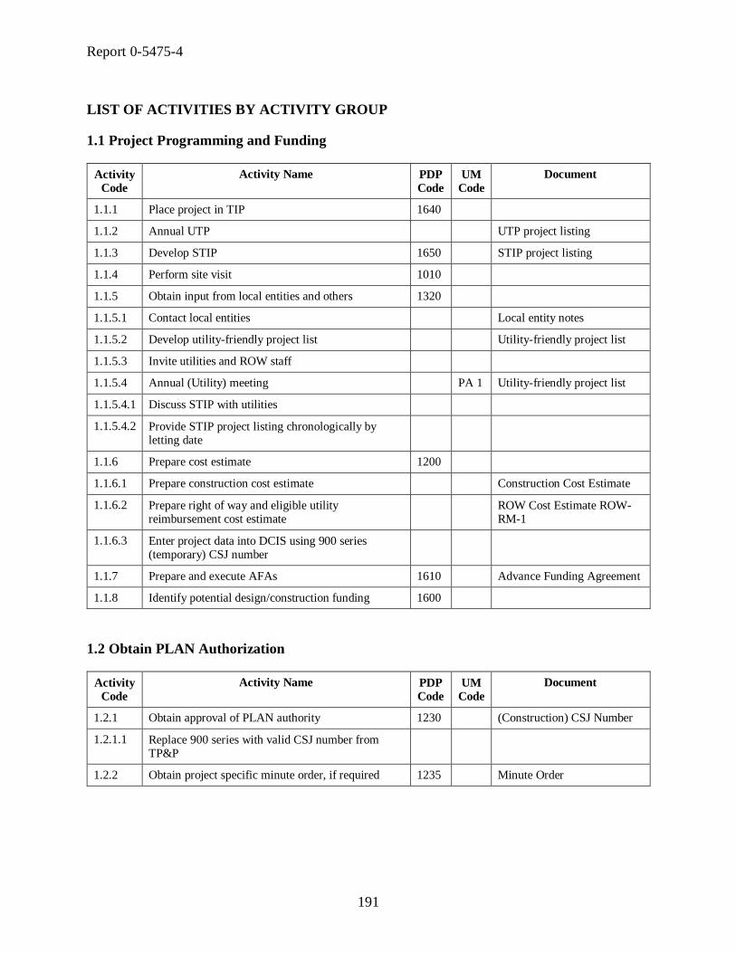
Report 0-5475-4
191
LIST OF ACTIVITIES BY ACTIVITY GROUP
1.1 Project Programming and Funding
Activity
Code
Activity Name PDP
Code
UM
Code
Document
1.1.1 Place project in TIP 1640
1.1.2 Annual UTP UTP project listing
1.1.3 Develop STIP 1650 STIP project listing
1.1.4 Perform site visit 1010
1.1.5 Obtain input from local entities and others 1320
1.1.5.1 Contact local entities Local entity notes
1.1.5.2 Develop utility-friendly project list Utility-friendly project list
1.1.5.3 Invite utilities and ROW staff
1.1.5.4 Annual (Utility) meeting PA 1 Utility-friendly project list
1.1.5.4.1 Discuss STIP with utilities
1.1.5.4.2 Provide STIP project listing chronologically by letting date
1.1.6 Prepare cost estimate 1200
1.1.6.1 Prepare construction cost estimate Construction Cost Estimate
1.1.6.2 Prepare right of way and eligible utility reimbursement cost estimate
ROW Cost Estimate ROW-RM-1
1.1.6.3 Enter project data into DCIS using 900 series (temporary) CSJ number
1.1.7 Prepare and execute AFAs 1610 Advance Funding Agreement
1.1.8 Identify potential design/construction funding 1600
1.2 Obtain PLAN Authorization
Activity
Code
Activity Name PDP
Code
UM
Code
Document
1.2.1 Obtain approval of PLAN authority 1230 (Construction) CSJ Number
1.2.1.1 Replace 900 series with valid CSJ number from TP&P
1.2.2 Obtain project specific minute order, if required 1235 Minute Order

Report 0-5475-4
192
1.3 Assign ROW-CSJ
Activity
Code
Activity Name PDP
Code
UM
Code
Document
1.3.1 Assign ROW-CSJ ROW-CSJ Number
1.4 Obtain DEVELOP Authorization
Activity
Code
Activity Name PDP
Code
UM
Code
Document
1.4.1 Obtain DEVELOP authority 1620
1.4.1.1 Send ranked project listing to TP&P Ranked project listing
1.4.1.2 Select projects for DEVELOP authorization
1.4.1.3 Forward project listing to Transportation
Commission
1.4.1.4 Approve projects through Minute Orders Minute Order
1.5 Obtain CONSTRUCT Authorization
Activity
Code
Activity Name PDP
Code
UM
Code
Document
1.5.1 Obtain CONSTRUCT authority 1630
1.5.1.1 Send ranked project listing to TP&P Ranked project listing
1.5.1.2 Select projects for CONSTRUCT authorization
1.5.1.3 Forward project listing to Transportation
Commission
1.5.1.4 Approve projects through Minute Orders Minute Order
2.1 Data Collection and Preliminary Utility Coordination
Activity
Code
Activity Name PDP
Code
UM
Code
Document
2.1.1 Initial Project Notification PA 2
2.1.1.1 Provide preliminary project description, scope,
letting schedule
2.1.1.2 Set date for preliminary design conference
2.1.1.3 Request block maps/markups from utilities
2.1.1.4 Identify responsible party at utility

Report 0-5475-4
193
2.1 Data Collection and Preliminary Utility Coordination (Continued)
Activity
Code
Activity Name PDP
Code
UM
Code
Document
2.1.2 Conduct Design Concept Conference (Preliminary
Design Conference)
2000 PA 3 Advanced Planning Risk
Analysis, Partial Design
Summary Report, Meeting
notes
2.1.2.1 Discuss preliminary design and schedule
2.1.2.2 Circulate Design Summary Report (DSR)
2.1.2.3 Discuss UAR, eligibility, expected magnitude of
impact
2.1.2.4 Obtain concurrence or disagreement on DSR
2.1.2.5 Discuss action plan for SUE
2.1.2.6 Complete parts of Design Summary Report (DSR)
2.1.2.7 Set date for Design Conference
2.1.3 Conduct early coordination with stakeholders 2110
2.1.3.1 Coordinate with district environmental coordinator
2.1.3.2 Coordinate with roadway design engineer
2.1.3.3 Identify possible construction methods
2.1.3.4 Identify environmental/design constraints
2.1.3.5 Explore design modifications and effect on natural resources
2.1.3.6 Identify resource and regulatory agencies and stakeholders
2.1.4 Obtain related data, plans, studies, and reports 2160 Environmental studies, Bicycle plans, As-built
construction plans, Right of
way maps, Bridge inventory
data, Traffic signal studies,
Geotechnical reports, Traffic
accident data, Archived
project history files,
Pavement Management
System data, Hydraulic
reports, Automated Road Inventory diagrams, Traffic
data, LPA plans
2.1.4.1 Research names of property owners
2.1.4.2 Identify and contact individuals having relevant information
2.1.4.3 Maintain inventory of information received

Report 0-5475-4
194
2.1 Data Collection and Preliminary Utility Coordination (Continued)
Activity
Code
Activity Name PDP
Code
UM
Code
Document
2.1.5 Obtain aerial
photography/planimetrics/DTMs/digital
orthophotography
2220
2.2 Preliminary Design (Schematic Design)
Activity
Code
Activity Name PDP
Code
UM
Code
Document
2.2.1 Determine right of way and access needs 2630
2.2.1.1 Develop plan to address identified encroachments
2.2.2 Obtain information on existing utilities 2180
2.2.2.1 Review recent area-wide aerial photography
2.2.2.2 Review as-built documentation
2.2.2.3 Provide project dimensions to utilities
2.2.2.4 Observe utility location markers in the field and note
owner’s name
2.2.2.5 Request utility location information from utilities Project dimensions
2.2.2.6 Develop preliminary utility inventory Preliminary utility inventory
2.2.3 Alternative selection 2300-
2340
Preliminary schematic
alternatives
2.2.4 Develop geometrics 2350-2380
Preferred alternative
2.2.5 Develop preferred geometric alignment 2500 Preferred geometric alignment
2.2.6 Perform hydrologic study 2610 Hydrologic study
2.2.7 Obtain approval of geometric schematic before public hearing
2880
2.2.8 Conduct public meeting 2260 Public meeting notes
2.2.10 Review geometric schematic with stakeholders 2860
2.2.11 Revise geometric schematic based on input from public hearing
2890
2.2.12 Obtain approval for final geometric schematic 2920 Geometric schematic

Report 0-5475-4
195
2.3 Environmental Documentation
Activity
Code
Activity Name PDP
Code
UM
Code
Document
2.3.1 Prepare ―Purpose and Need‖ statement 3240
2.3.2 Determine public involvement needs 3010
2.3.3 Determine type of environmental document to
prepare
3210
2.3.4 Process draft environmental document 3420
2.3.5 Conduct public hearing 3500 Public hearing notes
2.4 Environmental Clearance
Activity
Code
Activity Name PDP
Code
UM
Code
Document
2.4.1 Process draft environmental document 3420
2.4.2 Obtain environmental clearance 3600
3.1 PS&E Development (Detailed Design)
Activity
Code
Activity Name PDP
Code
UM
Code
Document
3.1.1 Conduct Design Conference 5020 PA 5 Geometric schematic, Design
Summary Report
3.1.2 Send latest project construction plans to all utility
owners
Preliminary construction
plans
3.1.3 Begin Detailed Design 5040-
5160
3.1.4 Invite utility companies to introduction meeting
3.1.5 Introduction meeting for utilities
3.1.6 Update potential utility conflict list Updated potential utility conflict list
3.1.7 Update design plans
3.1.8 Notify ROW and utility company
3.1.9 Send updated design plans to utility company
3.1.10 30% Design meeting PA 6
3.1.11 Send 30% Design plans if applicable
3.1.12 Determine general location of storm sewer trunk lines
3.1.13 Review data collection needs 5120

Report 0-5475-4
196
3.1 PS&E Development (Detailed Design) (Continued)
Activity
Code
Activity Name PDP
Code
UM
Code
Document
3.1.14 Refine hydrology study 5140
3.1.15 Complete drainage design
3.1.16 60% Design meeting PA 6
3.1.17 Request CONSTRUCT authorization
3.1.18 90% Design meeting PA 6
3.1.19 Update DCIS construction and right of way
estimates
3.2 PS&E Assembly/Design Review
Activity
Code
Activity Name PDP
Code
UM
Code
Document
3.2.1 Prepare PS&E package 5830 General notes, Cost estimate,
Certifications, Plan sheets,
Project agreement, PS&E
Submission Data Form 1002,
Special provisions, Standard and special specifications
3.2.2 Conduct district PS&E review 5840
3.2.3 District conducts final agreement/permit review 5855
3.2.4 Collect outside additional funding based on advance funding agreements
5860 Final Project Cost Estimate, Advance Funding
Agreements, Financial
Clearance Notification
3.2.5 District performs final review of PS&E 5900
3.2.6 Submit PS&E to Design Division 5910
4.1 Preliminary Utility Coordination
Activity
Code
Activity Name PDP
Code
UM
Code
Document
4.1.1 Provide input on utility-friendly project list Utility-friendly project list input
4.1.2 Attend annual (utility) meeting
4.1.3 Provide support for right of way estimate Right of way estimate support documentation
4.1.4 Attend Preliminary Design meeting

Report 0-5475-4
197
4.2 Preliminary Right Of Way Research
Activity
Code
Activity Name PDP
Code
UM
Code
Document
4.2.1 Enter project info into ROWIS using Construction CSJ
4.2.2 Request ROW-CSJ from ROW Division ROW-RM-CSJ Request
4.2.3 Review district request
4.2.4 Request ROW-CSJ from TP&P Division
4.2.5 Receive ROW-CSJ from TP&P Division ROW-CSJ Number
4.2.6 Perform preliminary right of way research 4000
4.2.6.1 Research abutting property ownership
4.2.6.2 Obtain old right of way maps
4.2.6.3 Establish existing right of way limits
4.2.6.4 Establish restrictions to state ownership (easements)
4.3 SUE Level C and D (Visual and Records)
Activity
Code
Activity Name PDP
Code
UM
Code
Document
4.3.1 Perform SUE Level D
4.3.2 Hire SUE consultant SUE contract, SUE work order
4.3.3 Perform SUE Level C and D SUE deliverables
4.3.4 Update utility layout Updated utility layout
4.4 Right Of Way Mapping Before Letting
Activity
Code
Activity Name PDP
Code
UM
Code
Document
4.4.1 Start right of way mapping
4.4.2 List utilities on right of way map cover sheet
4.4.3 Update right of way map with additional utilities, if applicable
4.4.4 Prepare right of way map 4300
4.4.4.1 Abstract map Geometric schematic
4.4.4.2 Preliminary map

Report 0-5475-4
198
4.4.4.3 Final map Map checklist ROW-MapCheck, Right of way map
4.4 Right Of Way Mapping Before Letting (Continued)
Activity
Code
Activity Name PDP
Code
UM
Code
Document
4.4.5 Update right of way map Map checklist ROW-
MapCheck, Right of way map
4.4.6 Forward new right of way map to ROW Division Right of way map
4.5 Obtain Right Of Way Release
Activity
Code
Activity Name PDP
Code
UM
Code
Document
4.5.1 Send right of way estimate update
4.5.2 Update/refine right of way cost estimate in DCIS
4.5.3 Approve right of way map Right of way map
4.5.4 Enter right of way and parcel data into ROWIS
4.5.5 Update/refine right of way cost estimate in DCIS
4.5.6 Release right of way project 4415 SA 4 Right of way map
4.6 SUE Level C (and Some B)
Activity
Code
Activity Name PDP
Code
UM
Code
Document
4.6.1 Identify existing utilities on geometric schematic 2640
4.6.1.1 Coordinate with district utility coordinator
4.6.1.2 Hire SUE consultant SUE contract, SUE work
order
4.6.1.3 Send preliminary schematic to utilities and request
markups
4.6.1.4 Perform SUE (Level B, C or D) SUE deliverables
4.6.1.5 Develop utility layout Utility layout
4.6.1.6 Collect utility information from utility owners
4.6.1.7 Develop list of potentially impacted utilities Potential utility conflict list
4.6.2 Identify potential utility conflicts 2650
4.6.2.1 Review preliminary schematic with district utility
coordinator
Potential utility conflict list

Report 0-5475-4
199
4.6.2.2 Locate utility conflicts in plan and profile
4.6.2.3 Develop utility conflict list Utility conflict list
4.6 SUE Level C (and Some B) (Continued)
Activity
Code
Activity Name PDP
Code
UM
Code
Document
4.6.2.4 Contact utility owners to discuss plans and address utility conflicts
4.7 Secure Federal, State and Local Funding Agreements
Activity
Code
Activity Name PDP
Code
UM
Code
Document
4.7.1 Verify Minute Order
4.7.2 Review contractual agreements
4.7.3 Obtain contractual agreements with LPAs 4400
4.7.3.1 Review local participation requirement
4.7.3.2 Review previously executed AFAs
4.7.3.3 Decide when and by whom right of way is acquired
4.7.3.4 Review utility conflict list Utility conflict list
4.7.3.5 Review approved right of way map if applicable
4.7.3.6 Execute ROW-RM-129 SA
3b
and
SA 6
Agreement to Contribute
Funds ROW-RM-129
4.7.3.7 Give local entity approved right of way map if
applicable
4.7.3.8 Execute ROW-RM-37 SA 3b
Contractual Agreement for ROW Procurement ROW-
RM-37
4.7.4 Federal Project Authorization and Agreement (FPAA)
SA 3a
4.7.5 Alternate Procedure approval from FHWA SA 5
4.8 Locate Utilities (SUE Level B and Some A)
Activity
Code
Activity Name PDP
Code
UM
Code
Document
4.8.1 Locate existing utilities 4200

Report 0-5475-4
200
4.8.1.1 Hire SUE consultant SUE contract, SUE work order
4.8.1.2 Perform SUE SUE deliverables
4.8.1.3 Update utility layout Updated utility layout
4.9 Right Of Way Acquisition Before Letting
Activity
Code
Activity Name PDP
Code
UM
Code
Document
4.9.1 Appraise parcels 4430 Contract for Appraisal Services ROW-A-2
4.9.2 Identify impediments to parcel acquisition 4420
4.9.3 Acquire right of way parcels
4.9.4 Review right of way map update
4.9.5 Request CONSTRUCT authorization
4.10 Utility’s Consultant Contract Approval
Activity
Code
Activity Name PDP
Code
UM
Code
Document
4.10.1 ROW approval of consultant contract if reimbursable
4.11 Agreements with Utilities
Activity
Code
Activity Name PDP
Code
UM
Code
Document
4.11.1 Prepare and execute joint-use/multiple-use agreements (acknowledgements)
4425
4.11.1.1 Review utility’s letter of no conflict Letter of no conflict
4.11.1.2 Execute Utility Joint Use Acknowledgement A Utility Joint Use Acknowledgement ROW-U-
JUAA
4.11.1.3 Execute Utility Joint Use Acknowledgement B Utility Joint Use
Acknowledgement ROW-U-
JUAB
4.11.2 Prepare and execute utility adjustment agreements 4620
4.11.2.1 LPA prepares Utility Adjustment Assembly for
approval

Report 0-5475-4
201
4.11.2.2 Prepare and submit draft agreement assembly to utility owners
4.11.2.3 Request for Determination of Eligibility SA 7
4.11.2.4 District approves utility consultant contract SA 8
4.11.2.5 Determine eligibility (district approval)
4.11 Agreements with Utilities (Continued)
Activity
Code
Activity Name PDP
Code
UM
Code
Document
4.11.2.6 LPA authorizes work
4.11.2.7 Prepare Utility Adjustment Assembly for approval Utility Adjustment Plans,
Utility adjustment checklist,
ROW-U-Adjcheck, Standard
Utility Agreement ROW-U-
35, Joint Use
Acknowledgement ROW-U-JUAA or ROW-U-JUAB,
Statement Covering Utility
Construction Contract Work
ROW-U-48, Compensable
Interest Certificate ROW-U-
84
4.11.2.8 Send agreement assembly to division for approval
4.11.2.9 Agreement assembly approval at district (Tier 1)
4.11.2.10 Agreement assembly approval at district (Tier 1 or
2)
4.11.2.11 Execute utility agreement
4.11.3 Coordinate utility adjustment plans 4610
4.11.3.1 Review SUE deliverables and utility conflict list
4.11.3.2 Invite one or more utility companies
4.11.3.3 Meeting with one or more utility companies
4.11.3.4 Develop utility adjustment plans Utility adjustment plans
4.11.4 LPA submits request for inclusion in highway
contract to district
4.11.5 Submit two sets of plans and explanation of need
4.11.6 Gather division approval for plans and methods of
installation
Advance Funding Agreement
Attachment ―I‖
4.11.7 Submit letter of recommendation
4.11.8 Process advance funding agreement Utility Advance Funding
Agreement

Report 0-5475-4
202
4.12 Locate Utilities (SUE Level A)
Activity
Code
Activity Name PDP
Code
UM
Code
Document
4.12.1 Perform SUE Level A
4.12.2 Update utility layout Updated utility layout
4.12.3 Submit SUE deliverables and utility layout SUE deliverables
4.13 Adjustment Monitoring and Reimbursement Before Letting
Activity
Code
Activity Name PDP
Code
UM
Code
Document
4.13.1 Clear right of way for utility adjustment
4.13.2 Utility owners adjust facilities 4630 SA 11
Reimbursable Authorization Letter ROW-U-13
4.13.2.1 Notify utility owners that agreements are executed
4.13.2.2 Maintain utility adjustment construction records
4.13.3 Meetings with utilities with outstanding adjustments
4.13.4 Reimburse utility owners for eligible adjustment costs
4650 SA 13
4.14 Utility and Right Of Way Certifications
Activity
Code
Activity Name PDP
Code
UM
Code
Document
4.14.1 Prepare right of way and encroachment certifications
4500
4.14.1.1 Research status of right of way acquisition and removal of identified encroachments
4.14.1.2 Prepare right of way encroachment certifications
4.14.2 Prepare utility clearance certifications 4640
4.14.2.1 Include form Utiladj 1 in PS&E
4.14.2.2 Include form Utiladj 2 in PS&E Certification for Utility Adjustment (Not Clear)
Utiladj2
4.14.2.3 Include triple zero special provision Certification for Utility
Adjustment (None or Clear)
Utiladj1
4.14.2.4 Attach form Utilstat Utility Status Data Sheet
Utilstat

Report 0-5475-4
203
4.15 Right Of Way Mapping After Letting
Activity
Code
Activity Name PDP
Code
UM
Code
Document
4.15.1 Update right of way map Map checklist ROW-
MapCheck, Right of way map
4.15.2 Forward new right of way map to ROW Division Right of way map
4.16 Right Of Way Acquisition After Letting
Activity
Code
Activity Name PDP
Code
UM
Code
Document
4.16.1 Appraise parcels 4430
4.16.2 Identify impediments to parcel acquisition 4420
4.16.3 Acquire right of way parcels
4.16.4 Review right of way map update Right of way map
4.17 Adjustment Monitoring and Reimbursement After Letting
Activity
Code
Activity Name PDP
Code
UM
Code
Document
4.17.1 Dispose of improvements 4490 Final disposition of ROW
Improvements ROW-RM-9
4.17.2 Clear right of way for utility adjustment
4.17.3 Preconstruction utility meeting
4.17.4 Utility owners adjust facilities 4630 SA
11
Utility adjustment checklist
ROW-U-Adjcheck,
Reimbursable Authorization Letter ROW-U-13
4.17.4.1 Notify utility owners that agreements are executed
4.17.4.2 Maintain utility adjustment construction records
4.17.5 Utility coordination meetings during construction PA 10
4.17.6 Reimburse utility owners for eligible adjustment costs
4650 SA 13
4.17.7 Receive utility’s as-built documentation As-built documentation

Report 0-5475-4
204
5.1 Final Processing and Letting
Activity
Code
Activity Name PDP
Code
UM
Code
Document
5.1.1 Perform financial clearance analysis 6000
5.1.2 Prepare and review draft (bid) proposal 6010
5.1.3 Obtain funding and approval of PS&E 6030 State Letter of Authorization
(State LOA), FPAA
5.1.4 Release final (bid) proposal 6100
5.1.5 Release final (bid) proposal 6100 Final bid proposal
5.1.6 Conduct bid opening 6150
5.1.7 Award contract 6210
6.1 Initial Utility Involvement
Activity
Code
Activity Name PDP
Code
UM
Code
Document
6.1.1 Attend annual meeting Utility-friendly project list
6.1.2 Provide feedback for eligible utility reimbursement
cost estimate
6.2 Preliminary Design Meeting
Activity
Code
Activity Name PDP
Code
UM
Code
Document
6.2.1 Receive project notification
6.2.2 Schedule attendance at Design Concept Conference
6.3 Initial Coordination and Markup
Activity
Code
Activity Name PDP
Code
UM
Code
Document
6.3.1 Receive project dimensions and provide preliminary
facility locations
As-built plans
6.3.2 Review preliminary schematic and markup utility
locations
Preliminary schematic
6.3.3 Review utility conflict list and make changes if applicable
Utility conflict list
6.3.4 Attend introduction meeting for utilities

Report 0-5475-4
205
6.4 Conflict Determination
Activity
Code
Activity Name PDP
Code
UM
Code
Document
6.4.1 Review preliminary plans Preliminary construction
plans
6.4.2 Hire consultant
6.4.3 Send existing drawings to consultant Existing utility installation
drawings
6.4.4 Consultant reviews utilities, redlines TxDOT
drawings
6.4.5 Review facilities, redline TxDOT drawings
6.4.6 Use SUE to add utilities without record to scale to
drawing
6.4.7 Identify conflicts, redline drawings, and submit to
TxDOT
SUE deliverables
6.4.8 Attend 30% Design meeting
6.4.9 Receive notification that adjustment is necessary
6.4.10 Receive updated design plans
6.4.11 Verify that conflict has been resolved
6.5 Utility Design
Activity
Code
Activity Name PDP
Code
UM
Code
Document
6.5.1 Receive 30% Design plans from TxDOT, if applicable
6.5.2 Prepare letter of no conflict and submit to TxDOT Prepare letter of no conflict and submit to TxDOT
6.5.3 Prepare and submit Joint Use Acknowledgement B Joint Use Acknowledgement ROW-U-JUAB
6.5.4 Prepare and submit Joint Use Acknowledgement A Joint Use Acknowledgement ROW-U-JUAA
6.5.5 Develop design to adjust facility
6.5.6 Utility exposes facility and ties it to control point
6.5.7 Attend 60% Design meeting
6.5.8 Utility sends findings to TxDOT
6.5.9 Prepare utility agreement
6.5.10 Receive utility offsets and 60% Design plans

Report 0-5475-4
206
6.5 Utility Design (Continued)
Activity
Code
Activity Name PDP
Code
UM
Code
Document
6.5.11 Receive notification that adjustment is necessary
6.5.12 Receive updated design plans
6.5.13 Meeting with ROW officials
6.5.14 Verify that conflict has been resolved
6.5.15 Update design and plan set if applicable
6.5.16 Complete cost estimate and schedule of work Compensable Interest
Certificate ROW-U-85 or
Affidavit of Property
Ownership (Utility Owner)
ROW-U-U1A, Utility
adjustment plans, Adjustment cost estimate, Statement
Covering Utility Construction
Contract Work ROW-U-48,
Standard Utility Agreement
ROW-U-35
6.5.17 Attend 90% Design meeting
6.5.18 Submit utility agreement
6.6 Utility Adjustment Before Letting
Activity
Code
Activity Name PDP
Code
UM
Code
Document
6.6.1 Receive notification to proceed Notification to proceed
6.6.2 Perform adjustment
6.6.3 Submit as-built documentation As-built documentation
6.6.4 Request payment within allowable timeframe Payment Request ROW-A-15
6.6.5 Receive reimbursement from TxDOT

Report 0-5475-4
207
6.7 Utility Adjustment After Letting
Activity
Code
Activity Name PDP
Code
UM
Code
Document
6.7.1 Meeting with TxDOT to discuss design plans
6.7.2 Update design and plan set if applicable
6.7.3 Receive notification to proceed Notification to proceed
6.7.4 Perform adjustment
6.7.5 Submit as-built documentation As-built documentation
6.7.6 Request payment within allowable timeframe Payment Request ROW-A-15
6.7.7 Receive payment from TxDOT


Report 0-5475-1
209
APPENDIX C. LOGICAL DATA MODELS OF
UTILITY DATA MANAGEMENT SYSTEM PROTOTYPE


211
Utility
Ac
co
mm
od
atio
n a
nd
Co
nflic
t T
rac
ke
r: L
og
ica
l D
ata
Mo
de
l
Su
bje
ct
Are
a:
AR
CS
DE
0-5
47
5 -
Te
xa
s T
ran
sp
ort
atio
n I
nstitu
te -
07
/31
/20
08
PR
OJ
EC
T L
INE
TX
DO
T U
NIQ
UE
ID
OB
JE
CT
ID
SH
AP
E
PR
OJ
EC
T L
INE
ID
PR
OJ
EC
T L
INE
FR
OM
DA
TE
PR
OJ
EC
T L
INE
TO
DA
TE
PR
OJ
EC
T L
INE
CO
MM
EN
T
TX
DO
T R
OU
TE
NA
ME
TX
DO
T R
OU
TE
NU
MB
ER
PR
OJ
EC
T L
INE
TY
PE
CO
DE
(F
K)
TX
DO
T C
OU
NT
Y P
OL
YG
ON
TX
DO
T U
NIQ
UE
ID
OB
JE
CT
ID
SH
AP
E
TX
DO
T C
OU
NT
Y N
UM
BE
R
TX
DO
T C
OU
NT
Y P
OL
YG
ON
FR
OM
DA
TE
TX
DO
T C
OU
NT
Y P
OL
YG
ON
TO
DA
TE
CO
UN
TY
NA
ME
CO
MP
TR
OL
LE
R C
OU
NT
Y N
UM
BE
R
DP
S C
OU
NT
Y N
UM
BE
R
FIP
S C
OU
NT
Y N
UM
BE
R
TX
DO
T D
IST
RIC
T N
UM
BE
R
TX
DO
T C
OU
NT
Y P
OL
YG
ON
CO
MM
EN
T
CO
UN
TY
TY
PE
ID (
FK
)
GE
OP
OL
ITIC
AL
FE
AT
UR
E
UT
ILIT
Y C
ON
FL
ICT
OU
TL
INE
TX
DO
T U
NIQ
UE
ID
OB
JE
CT
ID
SH
AP
E
UT
ILIT
Y C
ON
FL
ICT
OU
TL
INE
FR
OM
DA
TE
UT
ILIT
Y C
ON
FL
ICT
OU
TL
INE
TO
DA
TE
ST
AR
T S
TA
TIO
N M
EA
SU
RE
ME
NT
EN
D S
TA
TIO
N M
EA
SU
RE
ME
NT
MA
XIM
UM
OF
FS
ET
ME
AS
UR
EM
EN
T
MIN
IMU
M O
FF
SE
T M
EA
SU
RE
ME
NT
UT
ILIT
Y C
ON
FL
ICT
OU
TL
INE
CO
MM
EN
T
ME
AS
UR
EM
EN
T U
NIT
ID (
FK
)
PR
OJ
EC
T L
INE
TX
DO
T U
NIQ
UE
ID (
FK
)
UT
ILIT
Y C
ON
FL
ICT
EV
EN
T N
UM
BE
R (
FK
)
UT
ILIT
Y C
ON
FL
ICT
ID (
FK
)
TX
DO
T D
IST
RIC
T P
OL
YG
ON
TX
DO
T U
NIQ
UE
ID
OB
JE
CT
ID
SH
AP
E
TX
DO
T D
IST
RIC
T N
UM
BE
R
TX
DO
T D
IST
RIC
T P
OL
YG
ON
FR
OM
DA
TE
TX
DO
T D
IST
RIC
T P
OL
YG
ON
TO
DA
TE
DIS
TR
ICT
NA
ME
CO
MP
TR
OL
LE
R D
IST
RIC
T N
UM
BE
R
FIP
S D
IST
RIC
T N
UM
BE
R
TX
DO
T D
IST
RIC
T P
OL
YG
ON
CO
MM
EN
T
CO
UN
TY
TY
PE
CO
UN
TY
TY
PE
ID
CO
UN
TY
TY
PE
NA
ME
CO
UN
TY
TY
PE
DE
SC
RIP
TIO
N
PR
OJ
EC
T L
INE
TY
PE
PR
OJ
EC
T L
INE
TY
PE
CO
DE
PR
OJ
EC
T L
INE
TY
PE
NA
ME
PR
OJ
EC
T L
INE
TY
PE
DE
SC
RIP
TIO
N
Fig
ure
55.
UA
CT
Logic
al
Data
Mod
el,
Arc
SD
E S
ub
ject
Are
a.

212
Utility
Ac
co
mm
od
atio
n a
nd
Co
nflic
t T
rac
ke
r: L
og
ica
l D
ata
Mo
de
l
Su
bje
ct
Are
a:
DC
IS
0-5
47
5 -
Te
xa
s T
ran
sp
ort
atio
n I
nstitu
te -
07
/31
/20
08
DC
IS D
AT
A W
AR
EH
OU
SE
CO
NT
RO
L S
EC
TIO
N J
OB
NU
MB
ER
AC
TU
AL
LE
TT
ING
DA
TE
AD
DIT
ION
AL
RO
W A
MO
UN
T
AN
CE
ST
OR
CS
J 1
AN
CE
ST
OR
CS
J 2
AN
CE
ST
OR
CS
J 3
AN
CE
ST
OR
CS
J 4
AN
CE
ST
OR
CS
J 5
BE
GIN
NIN
G R
EF
ER
EN
CE
MA
RK
ER
DIS
PL
AC
EM
EN
T N
UM
BE
R
BE
GIN
NIN
G R
EF
ER
EN
CE
MA
RK
ER
NU
MB
ER
CO
NT
RA
CT
CS
J
CO
UN
TY
NU
MB
ER
DA
TE
LA
ST
RE
VIS
ION
DIS
TR
ICT
LE
TT
ING
DA
TE
EL
IGIB
LE
FE
DE
RA
L F
UN
DIN
G F
LA
G
EN
DIN
G R
EF
ER
EN
CE
MA
RK
ER
DIS
PL
AC
EM
EN
T N
UM
BE
R
EN
DIN
G R
EF
ER
EN
CE
MA
RK
ER
NU
MB
ER
EN
GIN
EE
R N
UM
BE
R
ES
TIM
AT
ED
CO
NS
TR
UC
TIO
N C
OS
T A
MO
UN
T
ES
TIM
AT
ED
CO
NS
TR
UC
TIO
N C
OS
T A
MO
UN
T D
AT
E
ES
TIM
AT
ED
RO
W C
OS
T
ES
TIM
AT
ED
RO
W C
OS
T D
AT
E
HIG
HW
AY
NU
MB
ER
LA
YM
AN
DE
SC
RIP
TIO
N1
LA
YM
AN
DE
SC
RIP
TIO
N2
LE
TT
ING
SC
HE
DU
LE
1
LIM
ITS
FR
OM
LIM
ITS
TO
LO
CA
L C
ON
TR
IBU
TIO
NS
AM
OU
NT
PR
OJ
EC
T N
UM
BE
R
RO
AD
WA
Y F
UN
CT
ION
AL
CL
AS
S C
OD
E
RO
W C
SJ
TIM
E L
AS
T R
EV
ISIO
N
TIP
FIS
CA
L Y
EA
R
TO
TA
L O
BL
IGA
TE
D A
MO
UN
T
Fig
ure
56.
UA
CT
Logic
al
Data
Mod
el,
DC
IS S
ub
ject
Are
a.

Report 0-5475-4
213
DOCUMENT TYPE
DOCUMENT TYPE ID
DOCUMENT TYPE NAME
DOCUMENT TYPE DESCRIPTION
DOCUMENT
DOCUMENT ID
DOCUMENT ACCESS RESTRICTION FLAG
DOCUMENT COMMENT
DOCUMENT DESCRIPTION
DOCUMENT SET MEMBER FLAG
DOCUMENT TITLE NAME
DOCUMENT TYPE ID (FK)
DOCUMENT FILENET TYPE CODE (FK)
DOCUMENT SET
DOCUMENT SET ID
DOCUMENT SET NUMBER
DOCUMENT SET TITLE NAME
DOCUMENT SET DESCRIPTION
DOCUMENT SET TYPE ID (FK)
DOCUMENT ACCESS
COMPANY ID (FK)
DOCUMENT ID (FK)
UTILITY CONFLICT EVENT DOCUMENT
DOCUMENT ID (FK)
UTILITY CONFLICT EVENT NUMBER (FK)
UTILITY CONFLICT ID (FK)
PROJECT DOCUMENT
CONTROL SECTION JOB NUMBER (FK)
DOCUMENT ID (FK)
FEATURE DOCUMENT
TABLE UNIQUE ID (FK)
DOCUMENT ID (FK)
FILE EXTENSION
FILE EXTENSION CODE
FILE EXTENSION NAME
FILE EXTENSION DESCRIPTION
DOCUMENT SET ITEM
DOCUMENT SET ID (FK)
DOCUMENT ID (FK)
DOCUMENT VERSION
DOCUMENT VERSION NUMBER
DOCUMENT ID (FK)
DOCUMENT VERSION ADDRESS
DOCUMENT VERSION CREATE DATE
DOCUMENT VERSION LAST MODIFY DATE
DOCUMENT VERSION RELEASE DATE
DOCUMENT VERSION LOGICAL NAME
DOCUMENT VERSION PHYSICAL NAME
DOCUMENT VERSION COMMENT
DOCUMENT VERSION STATUS CODE (FK)
FILE EXTENSION CODE (FK)
SYSTEM USER ID (FK)
DOCUMENT VERSION STATUS
DOCUMENT VERSION STATUS CODE
DOCUMENT VERSION STATUS NAME
DOCUMENT SET TYPE
DOCUMENT SET TYPE ID
DOCUMENT SET TYPE NAME
DOCUMENT SET TYPE DESCRIPTION
DOCUMENT TYPE ASSOCIATION
DOCUMENT TYPE ASSOCIATION CODE
DOCUMENT TYPE ID (FK)
Figure 57. UACT Logical Data Model, Document Subject Area.

Report 0-5475-4
214
NOTE: FEATURE is an index of all features in the enterprise, which includes
an entity (or table) identifier (TABLE UNIQUE ID) and a feature identifier
(TXDOT UNIQUE ID). TXDOT UNIQUE ID values are unique within each
feature table, but not across tables, and are generated at the feature table
level. The relationship between FEATURE and GAIP FEATURE is one of a
child and multiple parents, which ERwin does not handle, preventing the
definition of a simple foreign key constraint that would work during schema
generation. The referential integrity between FEATURE and all feature tables
must be maintained through code.
FEATURE
TABLE UNIQUE ID (FK)
GAIP FEATURE
CREATE USER NAME
CREATE DATE
EDIT USER NAME
EDIT DATE
GEOMETRY ERROR CODE
LEGAL TEXT
CREATION METHOD CODE (FK)
REVIEW FLAG (FK)
ASSET FEATURE
FEATURE SET ITEM
TABLE UNIQUE ID (FK)
FEATURE SET ID (FK)
FEATURE SET
FEATURE SET ID
FEATURE SET NAME
FEATURE SET DESCRIPTIONFEATURE NOTE
TABLE UNIQUE ID (FK)
NOTE ID (FK)PROPERTY RIGHT TYPE
PROPERTY RIGHT TYPE ID
PROPERTY RIGHT TYPE NAME
PROPERTY RIGHT TYPE DESCRIPTION
FEATURE PROPERTY RIGHT
TABLE UNIQUE ID (FK)
PROPERTY RIGHT ID (FK)
PROPERTY RIGHT SUBTYPE
PROPERTY RIGHT SUBTYPE ID
PROPERTY RIGHT SUBTYPE NAME
PROPERTY RIGHT SUBTYPE DESCRIPTION
PROPERTY RIGHT CLASS
PROPERTY RIGHT CLASS ID
PROPERTY RIGHT CLASS NAME
PROPERTY RIGHT CLASS DESCRIPTION
PROPERTY RIGHT
PROPERTY RIGHT ID
PROPERTY RIGHT CLASS ID (FK)
PROPERTY RIGHT TYPE ID (FK)
PROPERTY RIGHT SUBTYPE ID (FK)
FEATURE DEPRECIATION
TABLE UNIQUE ID (FK)
FEATURE DEPRECIATION ID
FEATURE DEPRECIATION ORIGINAL COST AMOUNT
FEATURE DEPRECIATION SERVICE START DATE
FEATURE DEPRECIATION SERVICE END DATE
OTHER FACILITY OTHER TYPE
TABLE UNIQUE ID (FK)
OTHER FACILITY OTHER TYPE NAME
OTHER FACILITY OTHER TYPE DESCRIPTION
CREATION METHOD
CREATION METHOD CODE
CREATION METHOD NAME
CREATION METHOD DESCRIPTION
REVIEW NEED
REVIEW FLAG
REVIEW DESCRIPTION
Figure 58. UACT Logical Data Model, Feature Subject Area.

Report 0-5475-4
215
Figure 59. UACT Logical Data Model, FileNet Subject Area.
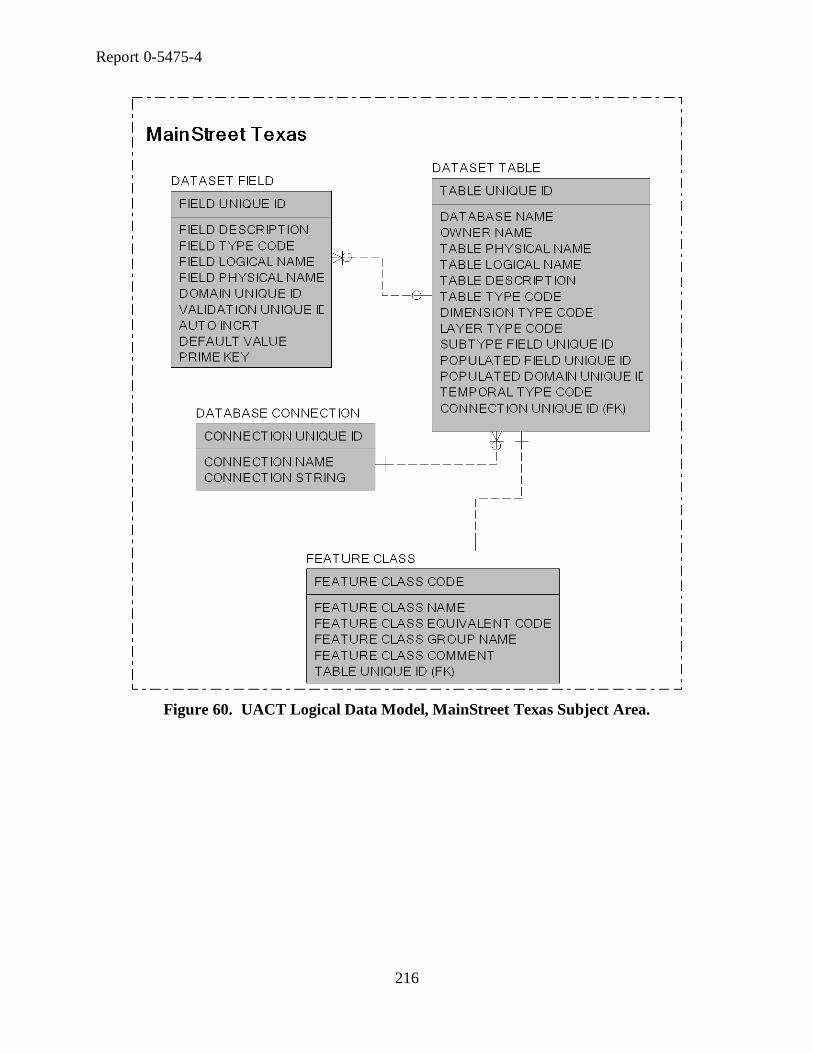
Report 0-5475-4
216
Figure 60. UACT Logical Data Model, MainStreet Texas Subject Area.

Report 0-5475-4
217
Utility Accommodation and Conflict Tracker: Logical Data Model
Subject Area: MEETING
0-5475 - Texas Transportation Institute - 07/31/2008
MEETING TYPE
MEETING TYPE ID
MEETING TYPE NAME
MEETING TYPE DESCRIPTION
MEETING
MEETING ID
MEETING NAME
MEETING DESCRIPTION
MEETING CREATION TIMESTAMP
MEETING START DATE
MEETING END DATE
MEETING LOCATION DESCRIPTION
MEETING TIMESTAMP
MEETING TYPE ID (FK)
SYSTEM USER ID (FK)
MEETING ATTENDANCE
MEETING ID (FK)
SYSTEM USER ID (FK)
MEETING ATTENDANCE ATTENDED FLAG
MEETING ATTENDANCE REMIND FLAG
MEETING ATTENDANCE REQUIRED FLAG
UTILITY CONFLICT MEETING
MEETING ID (FK)
UTILITY CONFLICT ID (FK)
PROJECT MEETING
CONTROL SECTION JOB NUMBER (FK)
MEETING ID (FK)
MEETING DOCUMENT
DOCUMENT ID (FK)
MEETING ID (FK)
MEETING NOTE
MEETING ID (FK)
NOTE ID (FK)
Figure 61. UACT Logical Data Model, Meeting Subject Area.

Report 0-5475-4
218
ROLE
ROLE ID
ROLE NAME
ROLE DESCRIPTION
CAPABILITY
CAPABILITY ID
CAPABILITY NAME
DEFAULT ROLE PERMISSION
DEFAULT ROLE PERMISSION ID
ROLE ID (FK)
PERMISSION ID (FK)
EFFECTIVE USER PERMISSION
EFFECTIVE USER PERMISSION ID
CONTROL SECTION JOB NUMBER (FK)
DEFAULT ROLE PERMISSION PRIVILEGE ID (FK)
PERMISSION ID (FK)
SYSTEM USER ID (FK)
DEFAULT ROLE PERMISSION PRIVILEGE
DEFAULT ROLE PERMISSION PRIVILEGE ID
DEFAULT ROLE PERMISSION ID (FK)
PRIVILEGE ID (FK)
BUSINESS AREA
BUSINESS AREA ID
BUSINESS AREA NAME
BUSINESS AREA DESCRIPTION
BUSINESS AREA SECTION
BUSINESS AREA SECTION ID
BUSINESS AREA SECTION NAME
BUSINESS AREA SECTION DESCRIPTION
BUSINESS AREA ID (FK)
PERMISSION
PERMISSION ID
BUSINESS AREA SECTION ID (FK)
CAPABILITY ID (FK)
Figure 62. UACT Logical Data Model, Permissions Subject Area.

Report 0-5475-4
219
UACT PROJECT
CONTROL SECTION JOB NUMBER (FK)
UACT PROJECT NAME
UACT PROJECT IMPORT TIMESTAMP
ROW PROJECT ID (FK)
PROJECT EVENT
PROJECT EVENT NUMBER
CONTROL SECTION JOB NUMBER (FK)
PROJECT EVENT TIMESTAMP
SYSTEM USER ID (FK)
PROJECT EVENT TYPE
PROJECT EVENT TYPE ID
PROJECT EVENT TYPE NAME
PROJECT EVENT TYPE DESCRIPTION
PROJECT ACTIVITY GROUP STATUS
PROJECT ACTIVITY GROUP STATUS ID
PROJECT ACTIVITY GROUP STATUS PERCENT
PROJECT ACTIVITY GROUP STATUS TIMESTAMP
CONTROL SECTION JOB NUMBER (FK)
PROJECT ACTIVITY GROUP ID (FK)
PROJECT EVENT NUMBER (FK)PROJECT ANCESTOR
PROJECT ANCESTOR ID
CSJ PARENT NUMBER
CONTROL SECTION JOB NUMBER (FK)
PROJECT ACTIVITY GROUP
PROJECT ACTIVITY GROUP ID
PROJECT ACTIVITY GROUP NAME
PROJECT ACTIVITY GROUP DESCRIPTION
PROJECT FEATURE
TABLE UNIQUE ID (FK)
CONTROL SECTION JOB NUMBER (FK)
PROJECT MANAGER TYPE
PROJECT MANAGER TYPE ID
PROJECT MANAGER DESCRIPTION
PROJECT MANAGER
PROJECT EVENT NUMBER (FK)
CONTROL SECTION JOB NUMBER (FK)
PROJECT MANAGER FROM TIMESTAMP
PROJECT MANAGER TO TIMESTAMP
PROJECT MANAGER TYPE ID (FK)
DOT USER ID (FK)
ROWIS CONNECTION
CONTROL SECTION JOB NUMBER (FK)
PROJECT ID (FK)
ROW PROJECT
ROW PROJECT ID
ROW PROJECT CONTRACT DATE
ROW PROJECT UTILITY PROCEDURE DATE
ROW PROJECT CONTRACT TYPE ID (FK)
ROW PROJECT FUNDING TYPE ID (FK)
FIMS CODE (FK)
FINANCIAL INFORMATION MANAGEMENT SYSTEM
FIMS CODE
FIMS CODE NAME
FIMS CODE DESCRIPTION
ROW PROJECT FUNDING TYPE
ROW PROJECT FUNDING TYPE ID
ROW PROJECT FUNDING TYPE NAME
ROW PROJECT FUNDING TYPE DESCRIPTION
ROW PROJECT CONTRACT TYPE
ROW PROJECT CONTRACT TYPE ID
ROW PROJECT CONTRACT TYPE NAME
ROW PROJECT CONTRACT TYPE DESCRIPTION
UTILITY ADJUSTMENT PROCEDURE
UTILITY ADJUSTMENT PROCEDURE ID
UTILITY ADJUSTMENT PROCEDURE NAME
UTILITY ADJUSTMENT PROCEDURE ACRONYM TEXT
UTILITY ADJUSTMENT PROCEDURE DESCRIPTION
PROJECT UTILITY ADJUSTMENT PROCEDURE
CONTROL SECTION JOB NUMBER (FK)
UTILITY ADJUSTMENT PROCEDURE ID (FK)
PROJECT EVENT TYPE PROJECT EVENT
CONTROL SECTION JOB NUMBER (FK)
PROJECT EVENT NUMBER (FK)
PROJECT EVENT TYPE ID (FK)
ALIGNMENT
ALIGNMENT ID
ALIGNMENT NAME
ALIGNMENT DESCRIPTION
CUSTOM ALIGNMENT
CUSTOM ALIGNMENT ID
CUSTOM ALIGNMENT NAME
CUSTOM ALIGNMENT DESCRIPTION
CONTROL SECTION JOB NUMBER (FK)
ALIGNMENT PROJECT
ALIGNMENT ID (FK)
CONTROL SECTION JOB NUMBER (FK)
DCIS PROJECT
CONTROL SECTION JOB NUMBER
DCIS PROJECT ACTUAL LETTING DATE
DCIS PROJECT ADDITIONAL ROW AMOUNT
DCIS BEGINNING RM DISPLACEMENT NUMBER
DCIS PROJECT BEGINNING RM NUMBER
DCIS PROJECT CONTRACT CSJ NUMBER
DCIS PROJECT COUNTY NUMBER
DCIS PROJECT DESCRIPTION
DCIS PROJECT DISTRICT LETTING DATE
DCIS PROJECT ENDING RMD NUMBER
DCIS PROJECT ENDING RM NUMBER
DCIS PROJECT ENGINEER NUMBER
DCIS ESTIMATED CONSTRUCTION COST AMOUNT
DCIS ESTIMATED CONSTRUCTION COST DATE
DCIS ESTIMATED ROW COST AMOUNT
DCIS ESTIMATED ROW COST DATE
DCIS PROJECT FEDERAL FUNDING FLAG
DCIS PROJECT HIGHWAY NUMBER
DCIS PROJECT LAST REVISION TIMESTAMP
DCIS LETTING SCHEDULE1 YEAR NUMBER
DCIS PROJECT LIMITS FROM DESCRIPTION
DCIS PROJECT LIMITS TO DESCRIPTION
DCIS PROJECT LOCAL CONTRIBUTION AMOUNT
DCIS PROJECT NUMBER
DCIS ROADWAY FUNCTIONAL CLASS CODE
DCIS PROJECT ROW CSJ NUMBER
DCIS TIP FISCAL YEAR NUMBER
DCIS PROJECT TOTAL OBLIGATED AMOUNT
Figure 63. UACT Logical Data Model, Project Subject Area.

Report 0-5475-4
220
Figure 64. UACT Logical Data Model, ROWIS Subject Area.

Report 0-5475-4
221
UACT ENTITY
UACT ENTITY ID
UACT ENTITY NAME
UACT ENTITY DEFINITION
MESSAGE
MESSAGE ID
MESSAGE TEXT
MESSAGE TYPE ID (FK)
MESSAGE TYPE
MESSAGE TYPE ID
MESSAGE TYPE NAME
MESSAGE TYPE DESCRIPTION
Figure 65. UACT Logical Data Model, System Subject Area.

Report 0-5475-4
222
USER EVENT
USER EVENT NUMBER
SYSTEM USER ID (FK)
USER EVENT TIMESTAMP
USER EVENT TYPE ID (FK)
USER EVENT TYPE
USER EVENT TYPE ID
USER EVENT TYPE NAME
USER EVENT TYPE DESCRIPTION
PROJECT COMPANY
CONTROL SECTION JOB NUMBER (FK)
COMPANY ID (FK)
COMPANY ROLE
ROLE ID (FK)
COMPANY ID (FK)
CONTROL SECTION JOB NUMBER (FK)
SYSTEM USER ROLE
ROLE ID (FK)
SYSTEM USER ID (FK)
Figure 66. UACT Logical Data Model, User Subject Area.

Report 0-5475-4
223
Figure 67. UACT Logical Data Model, UIR Subject Area.

Report 0-5475-4
224
UTILITY AGREEMENT ASSEMBLY
UAA ID
UAA U NUMBER
UAA HIGHWAY CONTRACT INCLUSION FLAG
UAA QUITCLAIM NEED FLAG
UAA QUITCLAIM NEED DATE
UAA STATE UTILITY CONTRACT FLAG
UAA UPPER LIMIT AMOUNT
UAA UPPER LIMIT DATE
UAA UJUA NEED FLAG
UAA UJUA NEED DATE
UAA COMMENT TEXT
UAA CONTRACTING PROCEDURE TYPE CODE (FK)
UAA PIP TYPE ID (FK)
UAA REIMBURSEMENT APPROACH ID (FK)
UAA UTILITY ADJUSTMENT TYPE ID (FK)
DOCUMENT SET ID (FK)
UTILITY AGREEMENT ASSEMBLY UTILITY CONFLICT
UTILITY CONFLICT ID (FK)
UAA ID (FK)
PAYMENT
PAYMENT ID
PAYMENT AMOUNT
PAYMENT DATE
PAYMENT TYPE ID (FK)
UAA ID (FK)
PAYMENT TYPE
PAYMENT TYPE ID
PAYMENT TYPE NAME
PAYMENT TYPE DESCRIPTION
ESTIMATE
ESTIMATE ID
ESTIMATE AMOUNT
ESTIMATE BETTERMENT RATIO NUMBER
ESTIMATE DATE
ACCOUNTING METHOD ID (FK)
ESTIMATE TYPE ID (FK)
UAA ID (FK)
ESTIMATE TYPE
ESTIMATE TYPE ID
ESTIMATE TYPE NAME
ESTIMATE TYPE DESCRIPTION
UTILITY BILL
UTILITY BILL ID
UTILITY BILL AMOUNT
UTILITY BILL RECORD NUMBER
UTILITY BILL RECEIVE DATE
UTILITY BILL OUT DATE
UTILITY BILL TYPE ID (FK)
UTILITY BILL COMMENT
SYSTEM USER ID (FK)
UAA ID (FK)
UTILITY BILL TYPE
UTILITY BILL TYPE ID
UTILITY BILL TYPE NAME
UTILITY BILL TYPE DESCRIPTION
UTILITY AGREEMENT ASSEMBLY EVENT
UTILITY AGREEMENT ASSEMBLY EVENT NUMBER
UAA ID (FK)
UTILITY AGREEMENT ASSEMBLY EVENT DATE
UTILITY AGREEMENT ASSEMBLY EVENT COMMENT
UAA EVENT TYPE ID (FK)
UTILITY AGREEMENT ASSEMBLY EVENT TYPE
UAA EVENT TYPE ID
UAA EVENT TYPE NAME
UAA EVENT TYPE DESCRIPTION
UTILITY JOINT USE ACKNOWLEDGEMENT
UJUA ID
UJUA TYPE CODE
UJUA TYPE NAME
UAA ID (FK)
UTILITY JOINT USE ACKNOWLEDGEMENT EVENT
UJUA EVENT NUMBER
UJUA ID (FK)
UJUA EVENT DATE
UJUA EVENT COMMENT
UJUA EVENT TYPE ID (FK)
UJUA EVENT TYPE
UJUA EVENT TYPE ID
UJUA EVENT TYPE NAME
UJUA EVENT TYPE DESCRIPTIONSUBSEQUENT ENCUMBRANCE
SUBSEQUENT ENCUMBRANCE ID
SUBSEQUENT ENCUMBRANCE AMOUNT
SUBSEQUENT ENCUMBRANCE DATE
UAA ID (FK)
UTILITY AGREEMENT ASSEMBLY REIMBURSEMENT APPROACH
UAA REIMBURSEMENT APPROACH ID
UAA REIMBURSEMENT APPROACH NAME
UAA REIMBURSEMENT APPROACH DESCRIPTION
UAA CONTRACTING PROCEDURE TYPE
UAA CONTRACTING PROCEDURE TYPE CODE
UAA CONTRACTING PROCEDURE TYPE NAME
UAA CONTRACTING PROCEDURE TYPE DESCRIPTION
PRE QUALIFIED CONTRACTOR
PREQUALIFIED CONTRACTOR ID
PREQUALIFIED CONTRACTOR NAME
PREQUALIFIED CONTRACTOR PHONE NUMBER
PLACE ID (FK)
ELIGIBILITY RATIO
ELIGIBILITY RATIO ID
ELIGIBILITY RATIO DATE
ELIGIBILITY RATIO NONELIGIBILE OCCUPANCY MEASUREMENT
ELIGIBILITY RATIO PERCENT
ELIGIBILITY RATIO SHEET NUMBER
COMPOSITE ELIGIBILITY RATIO ID (FK)
ELIGIBILITY RATIO TYPE ID (FK)
MEASUREMENT UNIT ID (FK)
UAA ID (FK)
UTILITY CONFLICT ID (FK)
ELIGIBILITY RATIO TYPE
ELIGIBILITY RATIO TYPE ID
ELIGIBILITY RATIO TYPE NAME
ELIGIBILITY RATIO TYPE DESCRIPTION
UTILITY AGREEMENT
UTILITY AGREEMENT ID
UTILITY AGREEMENT HIGHWAY CONTRACT FLAG
UTILITY AGREEMENT WORK STATEMENT TEXT
UAA ID (FK)
SCOPE OF WORK
SCOPE OF WORK ID
SCOPE OF WORK TEXT
UAA ID (FK)
SCOPE OF WORK LOCATION
SCOPE OF WORK LOCATION ID
SCOPE OF WORK LOCATION MEASUREMENT
SCOPE OF WORK ID (FK)
SOW LOCATION TYPE ID (FK)
SCOPE OF WORK LOCATION TYPE
SOW LOCATION TYPE ID
SOW LOCATION TYPE NAME
SOW LOCATION TYPE DESCRIPTION
QUITCLAIM DEED
QUITCLAIM DEED ID
QUITCLAIM DEED DATE
UAA ID (FK)
ACCOUNTING METHOD
ACCOUNTING METHOD ID
ACCOUNTING METHOD NAME
ACCOUNTING METHOD DESCRIPTION
COMPOSITE ELIGIBILITY RATIO
COMPOSITE ELIGIBILITY RATIO ID
COMPOSITE ELIGIBILITY RATIO ADJUSTMENT PERCENT
ELIGIBILITY RATIO PROPERTY RIGHT OCCUPANCY
ER PROPERTY RIGHT OCCUPANCY ID
ELIGIBILITY RATIO ELIGIBLE OCCUPANCY MEASUREMENT
ELIGIBILITY RATIO ID (FK)
MEASUREMENT UNIT ID (FK)
PROPERTY RIGHT ID (FK)
UAA PRE QUALIFIED CONTRACTOR
PREQUALIFIED CONTRACTOR ID (FK)
UAA ID (FK)
UTILITY AGREEMENT ASSEMBLY ATTACHMENT
UTILITY AGREEMENT ATTACHMENT CODE
UTILITY AGREEMENT ATTACHMENT NAME
UTILITY AGREEMENT ATTACHMENT DESCRIPTION
UTILITY AGREEMENT ASSEMBLY SEQUENCE
UTILITY AGREEMENT ASSEMBLY SEQUENCE ID
UTILITY AGREEMENT ATTACHMENT CODE (FK)
UAA ATTACHMENT COMPLETION INDICATOR
UAA ID (FK)
UTILITY AGREEMENT ATTACHMENT CODE (FK)
UAA ATTACHMENT COMPLETION INDICATOR FLAG
UAA UTILITY ADJUSTMENT TYPE
UAA UTILITY ADJUSTMENT TYPE ID
UAA UTILITY ADJUSTMENT TYPE NAME
UAA UTILITY ADJUSTMENT TYPE DESCRIPTION
WORK SCHEDULE OVERVIEW
WSO ID
WSO BIDDING START DATE
WSO BIDDING END DATE
WSO CLEAN UP START DATE
WSO CLEAN UP END DATE
WSO CONSTRUCTION START DATE
WSO CONSTRUCTION END DATE
WSO ENGINEERING START DATE
WSO ENGINEERING END DATE
WSO MATERIAL ACQUISITION START DATE
WSO MATERIAL ACQUISITION END DATE
WSO PERMITTING START DATE
WSO PERMITTING END DATE
WSO COMPLEX ADJUSTMENT FLAG
UAA ID (FK)
UAA PROPERTY INTEREST PROOF TYPE
UAA PIP TYPE ID
UAA PIP TYPE NAME
UAA PIP TYPE DESCRIPTION
MEASUREMENT UNIT
MEASUREMENT UNIT ID
MEASUREMENT UNIT CODE
MEASUREMENT UNIT NAME
Figure 68. UACT Logical Data Model, Utility Agreement Assembly Subject Area.

Report 0-5475-4
225
UTILITY CONFLICT
UTILITY CONFLICT ID
UTILITY CONFLICT ESTIMATED START DATE
UTILITY CONFLICT ESTIMATED COMPLETION DATE
UTILITY CONFLICT TIMESTAMP
CONTROL SECTION JOB NUMBER (FK)
UTILITY CONFLICT TYPE ID (FK)
NOTE
NOTE ID
NOTE TITLE TEXT
NOTE BODY TEXT
NOTE TIMESTAMP
NOTE REPLY ID
UTILITY CONFLICT EVENT TYPE
UTILITY CONFLICT EVENT TYPE ID
UTILITY CONFLICT EVENT TYPE NAME
UTILITY CONFLICT EVENT TYPE DESCRIPTION
DOCUMENT VERSION NOTE
DOCUMENT VERSION NUMBER (FK)
NOTE ID (FK)
DOCUMENT ID (FK)
DOCUMENT VERSION NOTE SCOPE FLAG
UTILITY CONFLICT EVENT NOTE
NOTE ID (FK)
UTILITY CONFLICT EVENT NUMBER (FK)
UTILITY CONFLICT ID (FK)
UCE NOTE SCOPE FLAG
UTILITY CONFLICT TYPE
UTILITY CONFLICT TYPE ID
UTILITY CONFLICT TYPE NAME
UTILITY CONFLICT TYPE DESCRIPTION
UTILITY CONFLICT FEATURE STATUS
UTILITY CONFLICT FEATURE STATUS ID
UTILITY CONFLICT FEATURE STATUS NAME
UTILITY CONFLICT FEATURE STATUS DESCRIPTION
UTILITY CONFLICT RESOLUTION STRATEGY
UTILITY CONFLICT RESOLUTION STRATEGY ID
UTILITY CONFLICT RESOLUTION STRATEGY NAME
UTILITY CONFLICT RESOLUTION STRATEGY DESCRIPTION
UTILITY CONFLICT RESOLUTION STRATEGY SET
UTILITY CONFLICT EVENT NUMBER (FK)
UTILITY CONFLICT ID (FK)
UCR STRATEGY SET RECOMMENDED FLAG
UCR STRATEGY SET USED FLAG
UTILITY CONFLICT RESOLUTION STRATEGY ID (FK)
UTILITY CONFLICT EVENT FEATURE
TABLE UNIQUE ID (FK)
UTILITY CONFLICT ID (FK)
UTILITY CONFLICT EVENT NUMBER (FK)
UCE FEATURE RESOLUTION ESTIMATE TIMESTAMP
UTILITY CONFLICT FEATURE STATUS ID (FK)
UTILITY CONFLICT EVENT
UTILITY CONFLICT EVENT NUMBER
UTILITY CONFLICT ID (FK)
UTILITY CONFLICT DESCRIPTION
UTILITY CONFLICT EVENT LEGAL DATE
UTILITY CONFLICT EVENT TIMESTAMP
SYSTEM USER ID (FK)
UTILITY CONFLICT EVENT TYPE ID (FK)
UTILITY CONFLICT LEGAL STATUS ID (FK)
UAR EXCEPTION
UAR EXCEPTION ID
UAR EXCEPTION AMOUNT
UAR EXCEPTION APPROVAL FLAG
UAR EXCEPTION LIMITS FROM TEXT
UAR EXCEPTION LIMITS TO TEXT
UAR EXCEPTION REQUEST RECEIVE DATE
UAR EXCEPTION REQUEST RESOLUTION DATE
UAR EXCEPTION COMMENT
UTILITY CONFLICT ID (FK)
UAR EXCEPTION TYPE ID (FK)
UAR EXCEPTION TYPE
UAR EXCEPTION TYPE ID
UAR EXCEPTION TYPE NAME
UAR EXCEPTION TYPE DESCRIPTION
UTILITY CONFLICT LEGAL STATUS
UTILITY CONFLICT LEGAL STATUS ID
UTILITY CONFLICT LEGAL STATUS NAME
UTILITY CONFLICT LEGAL STATUS DESCRIPTION
Figure 69. UACT Logical Data Model, Utility Conflict Subject Area.

Report 0-5475-4
226
Figure 70. UACT Logical Data Model, Utility Facility Database Subject Area.