DEVELOPMENT OF A STRUCTURAL COMPOSITE UNDERBODY · Southfield, MI Abstract The Automotive...
17
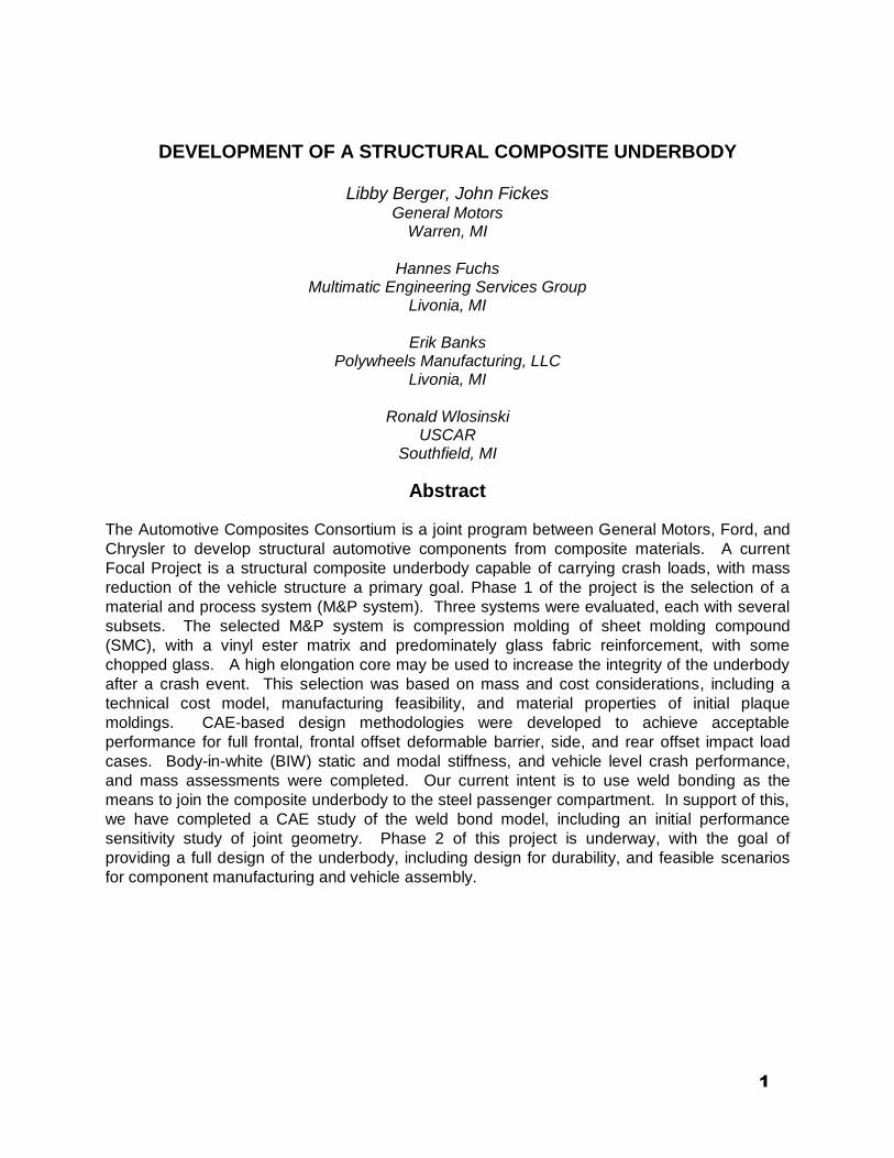
1 DEVELOPMENT OF A STRUCTURAL COMPOSITE UNDERBODY Libby Berger, John Fickes General Motors Warren, MI Hannes Fuchs Multimatic Engineering Services Group Livonia, MI Erik Banks Polywheels Manufacturing, LLC Livonia, MI Ronald Wlosinski USCAR Southfield, MI Abstract The Automotive Composites Consortium is a joint program between General Motors, Ford, and Chrysler to develop structural automotive components from composite materials. A current Focal Project is a structural composite underbody capable of carrying crash loads, with mass reduction of the vehicle structure a primary goal. Phase 1 of the project is the selection of a material and process system (M&P system). Three systems were evaluated, each with several subsets. The selected M&P system is compression molding of sheet molding compound (SMC), with a vinyl ester matrix and predominately glass fabric reinforcement, with some chopped glass. A high elongation core may be used to increase the integrity of the underbody after a crash event. This selection was based on mass and cost considerations, including a technical cost model, manufacturing feasibility, and material properties of initial plaque moldings. CAE-based design methodologies were developed to achieve acceptable performance for full frontal, frontal offset deformable barrier, side, and rear offset impact load cases. Body-in-white (BIW) static and modal stiffness, and vehicle level crash performance, and mass assessments were completed. Our current intent is to use weld bonding as the means to join the composite underbody to the steel passenger compartment. In support of this, we have completed a CAE study of the weld bond model, including an initial performance sensitivity study of joint geometry. Phase 2 of this project is underway, with the goal of providing a full design of the underbody, including design for durability, and feasible scenarios for component manufacturing and vehicle assembly.
Transcript of DEVELOPMENT OF A STRUCTURAL COMPOSITE UNDERBODY · Southfield, MI Abstract The Automotive...
1
DEVELOPMENT OF A STRUCTURAL COMPOSITE UNDERBODY
Libby Berger, John Fickes General Motors
Warren, MI
Hannes Fuchs Multimatic Engineering Services Group
Livonia, MI
Erik Banks Polywheels Manufacturing, LLC
Livonia, MI
Ronald Wlosinski USCAR
Southfield, MI
Abstract
The Automotive Composites Consortium is a joint program between General Motors, Ford, and
Chrysler to develop structural automotive components from composite materials. A current
Focal Project is a structural composite underbody capable of carrying crash loads, with mass
reduction of the vehicle structure a primary goal. Phase 1 of the project is the selection of a
material and process system (M&P system). Three systems were evaluated, each with several
subsets. The selected M&P system is compression molding of sheet molding compound
(SMC), with a vinyl ester matrix and predominately glass fabric reinforcement, with some
chopped glass. A high elongation core may be used to increase the integrity of the underbody
after a crash event. This selection was based on mass and cost considerations, including a
technical cost model, manufacturing feasibility, and material properties of initial plaque
moldings. CAE-based design methodologies were developed to achieve acceptable
performance for full frontal, frontal offset deformable barrier, side, and rear offset impact load
cases. Body-in-white (BIW) static and modal stiffness, and vehicle level crash performance,
and mass assessments were completed. Our current intent is to use weld bonding as the
means to join the composite underbody to the steel passenger compartment. In support of this,
we have completed a CAE study of the weld bond model, including an initial performance
sensitivity study of joint geometry. Phase 2 of this project is underway, with the goal of
providing a full design of the underbody, including design for durability, and feasible scenarios
for component manufacturing and vehicle assembly.

2
Introduction
The purpose of the Automotive Composites Consortium Focal Project 4 (ACC FP4) is to guide, focus, and showcase the technology research of the four ACC working groups (Materials, Processing, Joining, and Energy management). To this end, we are developing a structural composite underbody. The primary research outcomes of FP4 are:
A 2 ½ minute cycle time (100k vehicles per year, 2 shift operation)
Developing methods of joining and assembly of the underbody to the vehicle
Processes for fabricating areas of oriented reinforcement, such as fabric, within the time window
This project makes use of a donor vehicle, a large, rear-wheel-drive sedan, with architecture similar to, but not identical to, a current production vehicle. Since we have specified that this underbody should be structural, one of the vehicle selection criteria was that the underbody (i.e., the floorpan) should carry significant crash loads. Figure 1 shows the exploded view of the donor vehicle underbody and rails, and identifies the steel assembly targeted for replacement. The steel “sled runner” rails are also part of our design for purposes of mass reduction. Phase 1 of this project, reported herein, has been the selection of the materials and processes1 for the composite underbody based on a preliminary design concept2 suitable for CAE-based performance and mass assessment. Phase 2 will be a full design based on the donor vehicle, with material and processing trials using a shaped surrogate tool. Phase 3 will be fabrication and testing of the underbody.
Steel assembly
(16 stampings)
Sled runner rails
Steel assembly
(16 stampings)
Sled runner rails
Figure 1. Exploded view of the underbody and rails of the donor vehicle.
3
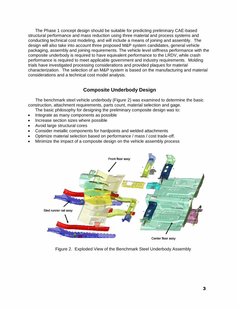
The Phase 1 concept design should be suitable for predicting preliminary CAE-based structural performance and mass reduction using three material and process systems and conducting technical cost modeling, and will include a means of joining and assembly. The design will also take into account three proposed M&P system candidates, general vehicle packaging, assembly and joining requirements. The vehicle level stiffness performance with the composite underbody is required to have equivalent performance to the LRDV, while crash performance is required to meet applicable government and industry requirements. Molding trials have investigated processing considerations and provided plaques for material characterization. The selection of an M&P system is based on the manufacturing and material considerations and a technical cost model analysis.
Composite Underbody Design
The benchmark steel vehicle underbody (Figure 2) was examined to determine the basic construction, attachment requirements, parts count, material selection and gage.
The basic philosophy for designing the preliminary composite design was to:
Integrate as many components as possible
Increase section sizes where possible
Avoid large structural cores
Consider metallic components for hardpoints and welded attachments
Optimize material selection based on performance / mass / cost trade-off.
Minimize the impact of a composite design on the vehicle assembly process
Front floor assy
Center floor assy
Sled runner rail assy
Front floor assy
Center floor assy
Sled runner rail assy
Figure 2. Exploded View of the Benchmark Steel Underbody Assembly

4
Based on an evaluation of the donor vehicle design, two composite concepts were proposed for further evaluation (Figure 3). The first concept was a single piece molded floor with ribs for maximum manufacturing efficiency, and the second concept was a bonded assembly for maximum structural efficiency. The team selected the ribbed concept as the primary design direction due to the program cycle time requirements, the reduced piece count, and the desire for minimum cost.
Vehicle Assembly / Joining
Traditional composite structures are often manufactured as bonded assemblies to meet structural requirements. In optimal, lightweight, multi-material designs, structural bonding provides enhanced seam integrity, gap bridging or tolerance functions and galvanic separation. In the high volume automotive environment, cycle time, body shop assembly process compatibility, and structural performance are all key requirements, and welding is a primary joining technique.
Underbody
rails
Ribs above
and below
the floor
Bonded
components
Ribbed Design Concept Bonded Design Concept
Underbody
rails
Ribs above
and below
the floor
Bonded
components
Ribbed Design Concept Bonded Design Concept
Figure 3. Preliminary design concepts: ribbed and bonded.
The combination of welding and bonding, weld bonding, is currently being implemented in
OEM body designs and assembly plants as a means of increasing stiffness, reducing mass, and improving durability. Weld bonding is currently envisioned as the primary joining process to meet the complex automotive requirements for the composite underbody. Specifically, the concept is to either embed, or otherwise attach metallic inserts or doublers to the composite to enable spot welding to the surrounding steel structure as well as to attach the structural underbody rails to the composite floor (see Figure 4). Adhesive would be applied to the joint prior to spot welding. Not only would this provide compatibility with current body shop welding processes for installing the underbody itself, but the spot welds would also serve as peel stoppers in the adhesive joints, provide fixturing during adhesive cure, and enhance overall joint durability and robustness.

5
Doubler width
Weld diameter
Adhesive
Steel doubler
Steel
Rocker
Composite floor
Doubler width
Weld diameter
Adhesive
Steel doubler
Steel
Rocker
Composite floor
Figure 4. Weld bond concept for steel section weld bonded to composite using a metal
doubler strip.
CAD Model
A 3-D CAD model of the preliminary ribbed design concept was developed to assess structural performance using CAE methods. The model represents the proposed joining concept and component integration. Material thickness and selection are M&P system specific and will be discussed in the following sections.
CAE Performance Assessment
The model was integrated into the full vehicle NVH (NASTRAN) and crash models (LS-DYNA) for the donor vehicle. The structural performance of the composite underbody was assessed as an integral part of the full donor vehicle. For Phase 1, the following key development load cases were considered:
BIW static torsional and bending stiffness
BIW modal response
NCAP 35 mph Full Frontal Impact
EuroNCAP/IIHS 40 mph Frontal Offset Deformable Barrier (ODB)
FMVSS214 33.5 mph Side Impact
FMVSS301 50 mph Rear Offset Impact
6
Design Material Properties
For the initial design assessments, surrogate static room temperature material properties were used to represent candidate material systems pending the availability of physical test data from molding trials. The primary materials under consideration were fiberglass composites, either randomly oriented or with fabric. Randomly oriented and fabric carbon fiber composites were evaluated to gain insight into maximum potential mass savings. Surrogate material property data was selected based on fiber volumes that could be reasonably achieved for the target M&P systems. During the latter stages of Phase 1, the tensile and compressive properties were updated for some candidate materials as preliminary test data became available. Four composite material reinforcement systems were evaluated in the design: (a) random fiberglass with a core, (b) glass fabric, (c) glass fabric with a core, and (d) carbon fiber with a core, where the core is a low density/high strain-to-failure composite. In these evaluations, processing was not considered.
Global Stiffness Performance
Several vehicle level stiffness and modal studies were conducted before selecting the ribbed design concept direction. Random fiberglass composite material properties were applied to the geometry of the benchmark steel model to evaluate the effect on the global BIW performance. These studies concluded that global vehicle stiffness is relatively insensitive to the floor stiffness as long as a minimum threshold stiffness is achieved. Assessments of the four composite reinforcement system selections confirmed that the static torsional BIW stiffness increased by up to 4.6%, and the static bending stiffness decreased by up to 2.6% relative to the baseline vehicle. The first bending and torsional modes were within 0.05 Hz of the baseline vehicle.
However, once the first vehicle crash simulations were run, it was found that the requirements to meet crash performance overshadowed the requirements for the vehicle level stiffness performance. Hence, the effort to develop feasible composite designs to meet crash requirements was prioritized.
Vehicle Crash Performance
Based on the results for the preliminary composite underbody stiffness model and the CAD model for the ribbed composite design concept, an initial LS-DYNA crash model was developed. The composite materials were represented by the MAT58 material model which requires orthotropic stiffness and strength properties, as well as several parameters that govern the post-failure material response. The required parameters were selected based on the surrogate material data, engineering judgment, and several model sensitivity studies.

7
Initial vehicle level crash simulations indicated that the most severe loading case for the underbody floor structure was the EuroNCAP/IIHS 40 mph Frontal ODB case. The initial studies indicated that the thicknesses required to meet global stiffness were insufficient for maintaining structural integrity of the structure during crash. To achieve acceptable crash performance, the most mass-effective methods were:
Optimizing the local material thickness and orientation to keep the strain levels sufficiently low to avoid net section material failure, while allowing localized failure
Addition of higher material strength wherever possible
Adding a low density, high elongation core (HEC) such as high modulus polypropylene (HMPP) to the laminate with a thickness of up to 2.5mm in strategic regions of the floor
Modification of the driveshaft to allow for additional 70mm axial collapse to minimize local material failure at the rear of the tunnel
Reducing the thickness of the carry-over steel underbody rail components
Reducing the ribbing height and deleting ribbing in some locations Using the above methods and an iterative design process, acceptable frontal ODB crash
performance was achieved for the donor vehicle with a composite underbody, using all of the composite material systems considered. Acceptable performance was defined as the absence of any net section failures, with a small amount of localized material damage deemed acceptable.
Upon meeting the crash performance requirements for the frontal ODB case, the four
reinforcement systems were evaluated for all four crash load cases outlined above. Some additional adjustment to the lay-ups was required to meet the full frontal impact and to account for the as-tested material properties before achieving acceptable performance.
By the end of the Phase 1, a total of 225 crash simulations (165 Frontal ODB, 19 full frontal,
26 side impact, and 15 rear impact crash) and 44 global stiffness analyses were conducted to arrive at a feasible lower mass solution for each material system design.
A Frontal ODB crash model setup and representative deformations for a fiberglass fabric composite design are shown in Figure 5. Note that full vehicle crash models were used in the simulations but only the floor structure, wheels, and a wire frame representing the vehicle outline are shown in the figure. As can be seen in the figure, the offset barrier imparts a severe compressive and shearing load in the vehicle which results in local damage and intrusion in the floor structure. A corresponding representative damage plot is shown in Figure 6. The red areas in the damage plot indicate regions of localized material damage due to impact. The crash pulses for the composite underbody designs were found to be compatible with typical occupant restraint systems.

8
Figure 5. Predicted deformed shape for proposed composite underbody from Frontal ODB
Thickness and Mass
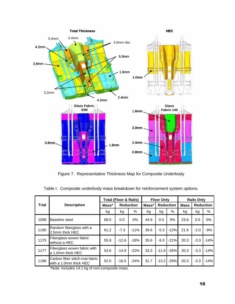
A representative map of the material thicknesses and orientations required to achieve acceptable crash performance for an all-fiberglass fabric underbody design proposal is illustrated in Figure 7. The total material thickness, the core thickness, and fiberglass fabric composite thicknesses are indicated in the figure. The total material thickness for the final four reinforcement designs ranges from 1.6mm to 8.1mm.
The mass for each of the reinforcement system designs is compared to the benchmark steel structure mass in Table I. The results indicate a total mass reduction potential of 7.3 to 16.5 kg vs. the total 68.5 kg baseline steel structure mass, which includes a secondary 2.0 to 3.3kg mass reduction as a result of a gage reduction in the carry-over design steel underbody rails. Considering only the floor (not accounting for the reduction in the rails) gives a mass reduction of 5.3 to 13.2kg, or up to 29%.

9
Figure 6. Representative predicted damage contour for proposed composite underbody from Frontal ODB
Figure 8 illustrates the predicted mass reduction and compares the four reinforcement
system designs (white bars) based on meeting the requirements for the four crash cases with revised material properties to the results of the initial predictions based only on the frontal ODB case (shaded bars) with initial material property assumptions. As can be seen in the figure, a large range of potential mass reduction is possible depending on the selected material system. The arrows in the figure indicate the change in mass for comparable material system designs as a result of considering additional load cases and the revised material properties.
It is clear from the studies conducted to date, that mass reduction and part thickness are
related to the strength of the materials investigated, where higher strength leads to lower mass and part thickness. Although not directly discussed here, materials with higher strength and also higher strain-to-failure properties would further reduce mass and thickness.
10
0.8mm
Glass Fabric
0/90
1.6mm
0.8mm
1.6mm
2.0mm
Glass
Fabric ±45
2.4mm
HEC
1.0mm
3.4mm5.0mm
3.8mm
5.0mm
1.6mm
3.2mm
4.2mm
4.2mm2.4mm
3.0mm ribs
Total Thickness
0.8mm
Glass Fabric
0/90
1.6mm0.8mm
Glass Fabric
0/90
1.6mm
0.8mm
1.6mm
2.0mm
Glass
Fabric ±45
2.4mm
0.8mm
1.6mm
2.0mm
Glass
Fabric ±45
2.4mm
HEC
1.0mm
HEC
1.0mm
3.4mm5.0mm
3.8mm
5.0mm
1.6mm
3.2mm
4.2mm
4.2mm2.4mm
3.0mm ribs
Total Thickness
Figure 7. Representative Thickness Map for Composite Underbody
Table I. Composite underbody mass breakdown for reinforcement system options.
Mass* Mass* Mass
kg kg % kg kg % kg kg %
1098 Baseline steel 68.5 0.0 0% 44.9 0.0 0% 23.6 0.0 0%
1190Random fiberglass with a
2.5mm thick HEC61.2 -7.3 -11% 39.6 -5.3 -12% 21.6 -2.0 -9%
1175Fiberglass woven fabric
without a HEC55.9 -12.6 -18% 35.6 -9.3 -21% 20.3 -3.3 -14%
1177Fiberglass woven fabric with
a 1.0mm thick HEC53.6 -14.9 -22% 33.3 -11.6 -26% 20.3 -3.3 -14%
1188Carbon fiber stitch-mat fabric
with a 1.0mm thick HEC52.0 -16.5 -24% 31.7 -13.2 -29% 20.3 -3.3 -14%
*Note: includes 14.1 kg of non-composite mass
Rails Only
Reduction Reduction ReductionTrial Description
Total (Floor & Rails) Floor Only

11
Figure 8. Predicted mass reduction for reinforcement system options.
Weld Bond Studies
A weld bond coupon was designed to evaluate the tensile structural joint performance using several finite element modeling methods (see Figure 9). The analysis indicated the results were sensitive to the selection of material model parameters so that physical test data would be required to select appropriate values. Further, sensitivity studies (see Figures 9 and 10) were conducted to establish how various joint and material parameters influence the joint strength. Relative to the nominal configuration, it was found that key joint parameters are the bond line length, adhesive strength, and metal substrate strength. These results will be used to guide physical testing planned for Phase 2.
Material and Process Systems
Three M&P systems have been evaluated for this project, based on manufacturing considerations, ability to deliver mass savings, and cost as predicted by technical cost modeling. The three M&P systems initially selected for evaluation were long fiber injection (LFI), nylon Direct Long Fiber Thermoplastic (DLFT), and sheet molding compound (SMC). Each of these systems has the potential for a combination of fabric and random fibers, as well as either glass or carbon reinforcement. In the processing trials, however, carbon fiber was not evaluated due to cost targets, a lack of available material, and a lack of dedicated processing equipment.

12
Figure 9. Weld bond coupon model and sensitivity study parameters.
Effects on Initial Peak Load
30
35
40
45
50
55
60
65
70
75
80
0 5 10 15 20 25 30
Variable
Lo
ad
in
20
ms
Adhesive Width
Adhesive Material
Metal Thickness
Metal Material
Weldstrip Material
Weldstrip Thickness
0mm
23mm
29mm
36mm
15MPa
39MPa
31MPa
57MPa
1.0mm
1.2mm
1.8mm
3.0mm
2.5mm
1010
340X
550X
c/o sled rail
1010
340X
550X
c/o
sled
rail
1.0mm
1.2mm
1.8mm
3.0mm2.5mm
Figure 10. Weld bond sensitivity study results.

13
LFI
The LFI process is currently in production with several relatively large composite components such as heavy truck panels and personal watercraft hulls. The LFI process as developed by Bayer utilizes robotic heads to chop glass into an open mold. As the glass is chopped, it is sprayed with a urethane resin. Bayer recommended a structural polyurethane (PU) system, Baydur 426, with a chop and spray LFI process. The molded samples are made with glass rovings that are dispensed from a reel and cut to any length before processing. PU and glass roving are introduced into the open mold simultaneously, with the chopped glass fiber being externally added to the PU spray jet. The molding is then cured in the closed mold. Bayer has successfully combined chopped LFI with sprayed continuous filament mats (CFM). Our needs in this project would require replacing this CFM with glass fabric, and combining this with chopped LFI.
Plaques were molded using chopped glass at loadings of 45, 50, 55 and 60% glass by
weight, and with continuous filament mat at 45, 50, 55 and 60% by weight. Molding trials with a woven glass fabric have not yet been successful.
Benefits for the LFI process include:
Easy mold access to apply local reinforcements
Low press tonnage, allowing for a large platen size which can easily accommodates the composite underbody assembly
Potentially fast cycle time using a carousel and rapid-heating tooling. Concerns for the LFI process are:
Developing a composite material with enough tensile & shear strength and strain-to-failure performance to meet crash requirements
Incorporating the fabric, which is needed for acceptable material properties
Ability of the urethane to withstand temperature requirements of the assembly process
Lack of existing infrastructure
Nylon DLFT
Nylon® DLFT is a derivative of the more traditional polypropylene resin-based DLFT process. In initial trials with nylon 6 at 50% glass, significant glass damming in the processing was seen, and the strengths of the tested plaques were very low. Subsequent trials varied the resin and glass formulations with glass volumes ranging from 40-50% by weight. Despite better processing, improved glass flow, and the addition of glass fabric, the material strength continued to be very low. Benefits for the nylon DLFT process:
Reduced cycle time
Recyclable Concerns for the nylon DLFT process:
Limited mold access to apply local reinforcements
Developing a composite material with enough tensile & shear strength and strain-to-failure performance to meet crash requirements
Incorporating the fabric, which is needed for acceptable material properties
Ability of the nylon to withstand temperature requirements of the assembly process
Press tonnage
Capital investment

14
Due to the nature of the DLFT process, adding glass fabric or an HMPP core to the charge
has proven to be very difficult. The fabric and core must be heated to ensure the nylon DLFT does not cool prior to being compressed in the mold. This requires additional heating elements and increases capital costs as well as complicating the manufacturing process. While the nylon DLFT was processed at 315°C, the HMPP core had to be processed at 160°C to prevent it from melting. How the two materials interact upon contact when building the charge is still under investigation but there is concern that the HMPP core rapidly cools the DLFT while the core is heated past its melting point, and loses the strain properties for which it is intended.
SMC
The third M&P system investigated is SMC. Polywheels currently compounds an unsaturated polyester/modified vinyl ester blend SMC in glass contents ranging from 27% to 55% glass by weight. For this project additional material strength and strain are required, demanding higher glass content and reinforcement fabrics be added. The glass content of the SMC was increased in increments of 5% until visible non-wetting conditions of the glass occurred at 70%. Further development led to a reduction of the glass content to 57% to improve process capability on the compounding line. Plaque molding trials demonstrated that additional reinforcement via glass fabrics can be incorporated into the SMC, utilizing both a uni-directional glass fabric (FGI W1300) and a bi-directional glass fabric (FGI 1854). These plaques showed a significant improvement in material properties. The bi-directional fabric proved to be the most useful for the underbody in various dynamic impact scenarios and therefore became the primary reinforcement selection. HMPP was sandwiched between layers of glass fabric to investigate the possible elongation provided by an HEC. In the initial trials the fabric and core were placed within the charges as dry material. This caused issues with wet out and trapped air within the plaques, causing blisters and inconsistent material properties. Subsequent trials utilized pre-compounded bi-directional glass fabric which improved material handling as well as reduced wet out issues. Filling ribs with the high glass content chopped glass SMC has also been successfully demonstrated. Using the bi-directional glass fabric as a base layer and chopped glass to fill the ribs, ribbed plaques consistently filled as long as the ribs were well lubricated. Benefits for the SMC process include:
Best composite material properties among the M&P systems evaluated
Relatively easy mold access to apply local reinforcements
Capable of surviving the elevated temperatures of ELPO and paint cure
Relatively low capital investment, as there is extensive SMC infrastructure within the automotive industry
Concerns for the SMC process are:
Developing a composite material with enough tensile & shear strength and strain-to-failure performance to meet crash requirements
Achieving 2 ½ minute cycle time
Press tonnage

15
Material Testing Results
Figure 11 shows the tensile and compressive properties of some of the tested materials. Of these materials, the highest strength and stiffness properties were from the glass fabric SMC. Addition of a high elongation core increases overall elongation to ultimate failure, albeit with a significantly lowered strength after peak load.
Technical Cost Model
In order to aid in the selection of the M&P system, we contracted with IBIS Associates to do a Technical Cost Model for the underbody, comparing the three processes discussed above and incorporating six reinforcement scenarios for each M&P system:
All random fiberglass
Random fiberglass with an HMPP core
All fiber glass fabric
Fiberglass fabric with an HMPP core
Random carbon fiber with an HMPP core
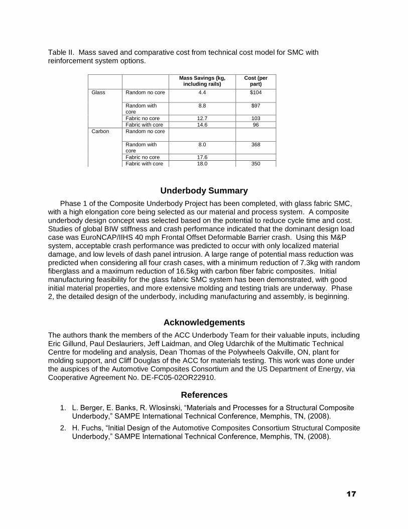
Carbon fiber fabric with an HMPP core This gives a total of eighteen different scenarios. The purpose of this cost model was to compare these systems to each other, not to get an absolute cost for the production of the underbody, nor to compare them to the steel underbody. The result of this study was that the LFI and SMC processes were almost identical in their costs. The DLFT process is more expensive, based on the higher cost of the nylon. However, if a lower-cost nylon can be used (which might be an issue because of temperature requirements), the DLFT is also cost competitive. The study concluded that the competitive position of the target processes will be determined by their respective material performance within each of the component designs. Material requirements will then drive the process rate and investment assumptions outlined in this study. Thus, each scenario’s design-material performance will determine its respective mass and part cost. Table II shows an evaluation of the possible mass saved for the reinforcement systems in SMC, as compared to the cost. For the glass fiber materials, the glass fabric with HMPP core saves 14.6 kg, for a cost of $96 per part. The carbon comparisons show a larger mass save of 18.0 kg, but at a cost of $350. Compared to fiberglass, the incremental cost per kg of mass saved of the carbon fiber is about $75, which is considered to be high.
Selection of M&P System
Based on the molding trials, in which SMC is the only one of the processes that incorporated the glass fabric as well as an HEC in a production-effective manner, the material properties, and the technical cost model, we have selected SMC with glass fabric and a high elongation core as our primary M&P system. Our future processing, material evaluation, and design efforts will focus on this material. However, both LFI and nylon DLFT show possible unique advantages, so we will continue to follow up on these processes.

16
Tensile and Compressive Stress Values
0
50
100
150
200
250
300
350
400
450
SMC 64%
chop
fabric SMC
0/90
fabric SMC
0/45/90
LFI-CFM
65%
PA DLFT
50%
Str
ess M
Pa
Tensile Stress 0/90 Tensile Stress 45
Compressive Stress 0/90 Compressive Stress 45
Tensile and Compressive Strain Values
0
1
2
3
4
5
6
SMC 64%
chop
fabric SMC
0/90
fabric SMC
0/45/90
LFI-CFM 65% PA DLFT
50%
Str
ain
%
Tensile Strain 0/90 Tensile Strain 45
Compressive Strain 0/90 Compressive Strain 45
Tensile and Compressive Modulus Values
0
5
10
15
20
25
30
35
40
SMC 64%
chop
fabric SMC
0/90
fabric SMC
0/45/90
LFI-CFM 65% PA DLFT
50%
Mo
du
lus G
Pa
Tensile Modulus 0/90 Tensile Modulus 45
Compressive Modulus 0/90 Compressive Modulus 45
A
C
B
Figure 11. Comparison of mechanical properties of chopped-glass and fabric SMC, CFM LFI, and chopped-glass DLFT. Values labeled “0/90” are the average of the 0° and 90° properties. (A) Stress. (B) Strain. (C) Modulus.
17
Table II. Mass saved and comparative cost from technical cost model for SMC with reinforcement system options.
Underbody Summary
Phase 1 of the Composite Underbody Project has been completed, with glass fabric SMC, with a high elongation core being selected as our material and process system. A composite underbody design concept was selected based on the potential to reduce cycle time and cost. Studies of global BIW stiffness and crash performance indicated that the dominant design load case was EuroNCAP/IIHS 40 mph Frontal Offset Deformable Barrier crash. Using this M&P system, acceptable crash performance was predicted to occur with only localized material damage, and low levels of dash panel intrusion. A large range of potential mass reduction was predicted when considering all four crash cases, with a minimum reduction of 7.3kg with random fiberglass and a maximum reduction of 16.5kg with carbon fiber fabric composites. Initial manufacturing feasibility for the glass fabric SMC system has been demonstrated, with good initial material properties, and more extensive molding and testing trials are underway. Phase 2, the detailed design of the underbody, including manufacturing and assembly, is beginning.
Acknowledgements
The authors thank the members of the ACC Underbody Team for their valuable inputs, including Eric Gillund, Paul Deslauriers, Jeff Laidman, and Oleg Udarchik of the Multimatic Technical Centre for modeling and analysis, Dean Thomas of the Polywheels Oakville, ON, plant for molding support, and Cliff Douglas of the ACC for materials testing. This work was done under the auspices of the Automotive Composites Consortium and the US Department of Energy, via Cooperative Agreement No. DE-FC05-02OR22910.
References
1. L. Berger, E. Banks, R. Wlosinski, “Materials and Processes for a Structural Composite Underbody,” SAMPE International Technical Conference, Memphis, TN, (2008).
2. H. Fuchs, “Initial Design of the Automotive Composites Consortium Structural Composite Underbody,” SAMPE International Technical Conference, Memphis, TN, (2008).
Mass Savings (kg, including rails)
Cost (per part)
Glass Random no core 4.4 $104
Random with core
8.8 $97
Fabric no core 12.7 103
Fabric with core 14.6 96
Carbon Random no core
Random with core
8.0 368
Fabric no core 17.6
Fabric with core 18.0 350