Throughput Biodosimetry System Fast Image Analysis for the ...
Int. J. Biomechatronics and Biomedical Robotics, Vol. 1, No. 2, 2010 115
Copyright © 2010 Inderscience Enterprises Ltd.
Development of a robotically-based automated biodosimetry tool for high-throughput radiological triage
Youhua Chen*, Jian Zhang, Hongliang Wang, Nabil Simaan and Y. Lawrence Yao Columbia University, 220 S.W. Mudd Building, 500 West 120th Street, New York, NY 10027 USA E-mail: [email protected] E-mail: [email protected] E-mail: [email protected] E-mail: [email protected] E-mail: [email protected] *Corresponding author
Guy Garty, Yanping Xu, Oleksandra V. Lyulko, Helen C. Turner, Gerhard Randers-Pehrson and D.J. Brenner Columbia University, 136 S. Broadway, Irvington, NY 10533 USA E-mail: [email protected] E-mail: [email protected] E-mail: [email protected] E-mail: [email protected] E-mail: [email protected] E-mail: [email protected]
Abstract: To provide the best opportunities for life-saving interventions in the event of a radiological or nuclear threat, there is an urgent need to improve the speed and efficiency of biodosimetric assays for triage and therapy. A rapid automated biodosimetric system used to assess thousands of individual radiation exposure doses is helpful to curb mass panic, and to conserve limited medical resources. This paper presents the development of a new robotically-based automated biodosimetry tool (RABiT). The RABiT is capable of automating two mature biodosimetry assays: the micronucleus and γ-H2AX assay. The design considerations guiding the hardware and software architecture are presented with focus on ease of implementation, methods of communication and need for real-time control versus soft time control cycles. Advanced technological developments for the RABiT including multipurpose gripper, non-contact laser cutting, automated biology protocols and transferring of the samples to a transparent substrate and high-speed multiple camera imaging are described in detail. The evaluation results show that the RABiT prototype has a throughput of 5,859 samples in an 18-hour duty cycle.
Keywords: biomedical automation; robotic manipulation; biodosimetry; cell harvesting.
Reference to this paper should be made as follows: Chen, Y., Zhang, J., Wang, H., Simaan, N., Yao, Y.L., Garty, G., Xu, Y., Lyulko, O.V., Turner, H.C., Randers-Pehrson, G. and Brenner, D.J. (2010) ‘Development of a robotically-based automated biodosimetry tool for high-throughput radiological triage’, Int. J. Biomechatronics and Biomedical Robotics, Vol. 1, No. 2, pp.115–125.
Biographical notes: Youhua Chen received his BEng and his MEng both in Mechanical Engineering from Shanghai Jiao Tong University, Shanghai, China, in 2000 and 2003, respectively. He received his PhD in Mechanical Engineering from North Carolina State University, Raleigh, NC, USA, in 2007. He is serving as a Post Doctoral Fellow jointly at Advanced Robotics and Mechanism Applications Laboratory and Advanced Manufacturing Laboratory at Columbia University, New York, USA. His current research interests include biomedical automation and robotics to enhance the effectiveness of clinical or biomedical procedures.
116 Y. Chen et al.
Jian Zhang received his BEng in Control Science and Engineering from Harbin Institute of Technology, Harbin, China, in 2005, his MS and MPhil in Mechanical Engineering from Columbia University, New York, NY, in 2006 and 2008, respectively. He is currently working towards his PhD in the Department of Mechanical Engineering, Columbia University. He has become a student member of IEEE and ASME in 2008. His paper ‘A pilot study of robot-assisted cochlear implant surgery using steerable electrode arrays’, won best student paper in MICCAI (International Conference on Medical Image Computing and Computer-Assisted Intervention) in Copenhagen, Denmark, in 2006. His current research interests include flexible robots, robots for medical surgery, mechatronics, robotics and control.
Hongliang Wang received his BE from Shanghai Jiao Tong University in 2003, and his ME from Harbin Institute of Technology in 2006, China, both in Mechanical Engineering. He joined Manufacturing Research Laboratory as a PhD candidate at Columbia University in 2008. His current graduate research focused on laser material processing in solar cell application.
Nabil Simaan received his BS (1996), MSc (1999), and PhD (2002) in Mechanical Engineering from the Technion-Israel Institute of Technology. His graduate research focused on the design of parallel robots for medical applications and stiffness synthesis. Subsequently, he served as a Visiting Research Scientist at Johns Hopkins NSF ERC-CISST where he focused on surgical assistance in confined spaces. In 2005, he joined Columbia University as an Assistant Professor and Director of the Advanced Robotics and Mechanisms Applications (ARMA) Laboratory. In 2009 he received the NSF Career award and in 2010 he was promoted to an Associate Professor rank.
Y. Lawrence Yao is a Professor and Chair of the Department of Mechanical Engineering at Columbia University, where he also serves as Director of Manufacturing Research Laboratory (MRL). Before joining Columbia in 1994, he served as a Senior Lecturer in the School of Mechanical and Manufacturing Engineering at the University of New South Wales, Sydney, Australia. He received his PhD from the University of Wisconsin-Madison in 1988, following his MS from the same institute, and BE from the Shanghai Jiao Tong University, China, all in Mechanical Engineering. He currently serves on the Board of Directors, Laser Institute of America, and on the Board of Directors, North American Manufacturing Research Institute of SME. He also serves as Associate Editor of ASME Transactions Journal of Manufacturing Science and Engineering, SME Journal of Manufacturing Processes, SME Journal of Manufacturing Systems, and High Temperature Material Processes: An International Journal, France.
Guy Garty received his MS and PhD in Physics from the Weizmann Institute of Science, Rehovot, Israel in 1997 and 2004, respectively. His dissertations were on electron-counting detectors and ion-counting nanodosimetry, respectively. He was then a Post-doctoral Research Scientist, an Associate Research Scientist and is currently a Research Scientist at the Radiological Research Accelerator Facility (RARAF), Center for Radiological Research, Columbia University, Irvington, New York, USA. His research interests include automated biodosimetry, high-throughput imaging, microbeam technology, nanodosimetry, and detector physics.
Yanping Xu received his PhD in Physics from North Carolina State University, USA, in 2006. His dissertation was Ultra cold neutron source. He is currently a Post-doctoral Research Scientist at the Radiological Research Accelerator Facility (RARAF), Center for Radiological Research, Columbia University, Irvington, New York, USA. His research interests include particle microbeam technology, laser light scattering technology, biodosimetry and computing bio-physics.
Oleksandra Lyulko received her MPhil in Physics from Columbia University in 2005. She is currently pursuing her PhD at the Center for Radiological Research, Columbia University, New York, NY and working as a Graduate Research Assistant at the Radiological Research Accelerator Facility (RARAF), Irvington, NY. Her research interests include non-stain imaging, interferometry, polarisation microscopy, high-throughput biodosimetry and automated image analysis.
Helen Turner received her MSc in Toxicology from the Department of Biochemistry, Birmingham University, UK and her PhD from the Department of Optometry and Vision Science, Cardiff University, Cardiff, UK, in 1993–1997. Her PhD was to determine transmembrane electrolyte movement of ions across the rabbit corneal endothelium in the maintenance of corneal transparency. Following her PhD, she then took a position as a Post-doctoral Fellow in the Department of Ophthalmology, Mount Sinai School of Medicine, New York, NY. Here she became an Assistant Professor. Her primary areas of focus include the
Development of a robotically-based automated biodosimetry tool for high-throughput radiological triage 117
physiology of dry eye disease and cataract formation. Presently, she is a Research Associate at the Center for Radiological Research, Columbia University, New York, NY where her primary areas of focus include automation and optimisation of biodosimetry assays, rapid high-throughput radiation biodosimetry and dynamics of radiation induced DNA damage pathways.
Gerhard Randers-Pehrson received his PhD in Physics from the University of Maryland, College Park, Maryland, USA in 1979. His dissertation involved the study of the Jπ=3+ doublet in beryllium-8 at 19 MeV. He was a Post Doctoral Research Associate in Neutron Physics at Ohio University, Athens, Ohio, USA from 1979 to 1982. He has held the positions of Associate Research Scientist (1982–1997) and Research Scientist (1997–2006) and is currently a Senior Research Scientist at the Center for Radiological Research. His interests include microbeam facilities, radiation biology, and substance detection.
David Brenner is the Director of the Columbia University Center for Radiological Research; Director of Radiological Research Accelerator Facility, and Principal Investigator of Center for High-Throughput Minimally-Invasive Radiation Biodosimetry. He focuses on developing mechanistic models for the effects of ionising radiation on living systems, both at the chromosomal and the animal (or human) levels. He divides his research time between the effects of high doses of ionising radiation (relating to radiation therapy) and the low doses of radiation (relating to radiological, environmental and occupational exposures). He is the author of two books and has published over 200 papers in the peer-reviewed scientific literature.
1 Introduction
Biodosimetry assay automation for radiological triage is becoming a top priority need to help the nation prepare for the eventuality of a terrorist nuclear attack or a radiological dispersion device scenario (Pellmar and Rockwell, 2005). If there is an improvised nuclear device (IND) or radiological dispersal device (RDD) scenario, people will require assessment of their radiation exposures whatever they have received medically significant doses of radiation, or not (Coleman and Parker, 2009). Medical facilities will be severely burdened with mass panic because the general population would not carry physical dosimeters. A rapid biodosimetric system that can examine samples, such as blood, from thousands of exposed individuals is needed to handle this situation.
The spectrum of automation approaches of biomedical instruments includes robots that mimic human operations, hard automation systems with full integration, and more recently, miniature micro-fluidic system (Meldrum et al., 2005). Up to now, many researchers have been challenging on designing a fully automated ultra-high throughput biodosimetry system, based on robotic material handling and high speed imaging systems. Meldrum et al. (2005) presented a capillary-based fluid handling system, called ACAPELLA-5K (A5K), capable of preparing mixtures of sample and reagents at a throughput of 5,000 preparations in eight hours. Kachel et al. (2006) designed a custom-made automated system capable of isolating DNA plasmids at a rate of 1,600 plasmids in 12 hours. Prasanna et al. (2005) proposed the automation of cytogenetic biodosimetry featuring a throughput of 500 samples per week. Soldatova et al. (2006) commissioned a new robotic system for investigations of gene function capable of handling more than 1,000 samples a day. However, the proposed solutions were directed toward automating sample handling and imaging systems rather than the automation of the complete
biological protocol. Despite the robustness and adaptability of existing biodosimetric approaches, the process is tedious and time-consuming with limited sample throughput.
Although several cytogenetically-based bioassays have been partially automated (Schunck et al., 2004; Martin et al., 2007), we know of no other system designed for complete automation from sample preparation through imaging to data analysis. In this paper, we propose a robotically-based automated biodosimetry tool (RABiT) that automates two biodosimetric assays: micronucleus (Fenech et al., 2003; IAEA, 2001) and γ-H2AX (Nakamura et al., 2006) for use in radiological triage. Specifically, the RABiT is capable of handling small blood samples, isolating blood lymphocytes, simultaneous staining, fast imaging and radiation exposure analysis. The main contribution of this paper is the design and development of the integration work including hardware and software architectures to implement automated high-throughput biodosimetry for radiological triage.
This paper is organised as follows. In Section 2, the overview and challenges of the RABiT are discussed. Section 3 describes the design and development for the proposed RABiT. The experimental results and performance evaluating are presented in Section 4. Finally, Section 5 concludes the paper.
2 Overview of the RABiT
The RABiT was proposed to automate two mature biodosimetry assays: micronucleus and γ-H2AX yields in lymphocytes. The system is designed to handle the entire sequential tasks from blood collection to imaging and analysis of radiation biomarkers.
The system was developed to meet the following performance requirements:
118 Y. Chen et al.
1 use 96-well plates as the sample reaction and cleanup conveyance vessel
2 achieve high throughput – 6,000 samples per 18 hours day
3 incorporate multipurpose grippers and path planning to optimise robot manipulation
4 consider system robustness for high reliability and repeatability
5 avoid cross contamination among samples
6 protect vulnerable lymphocytes from over heat and pressure.
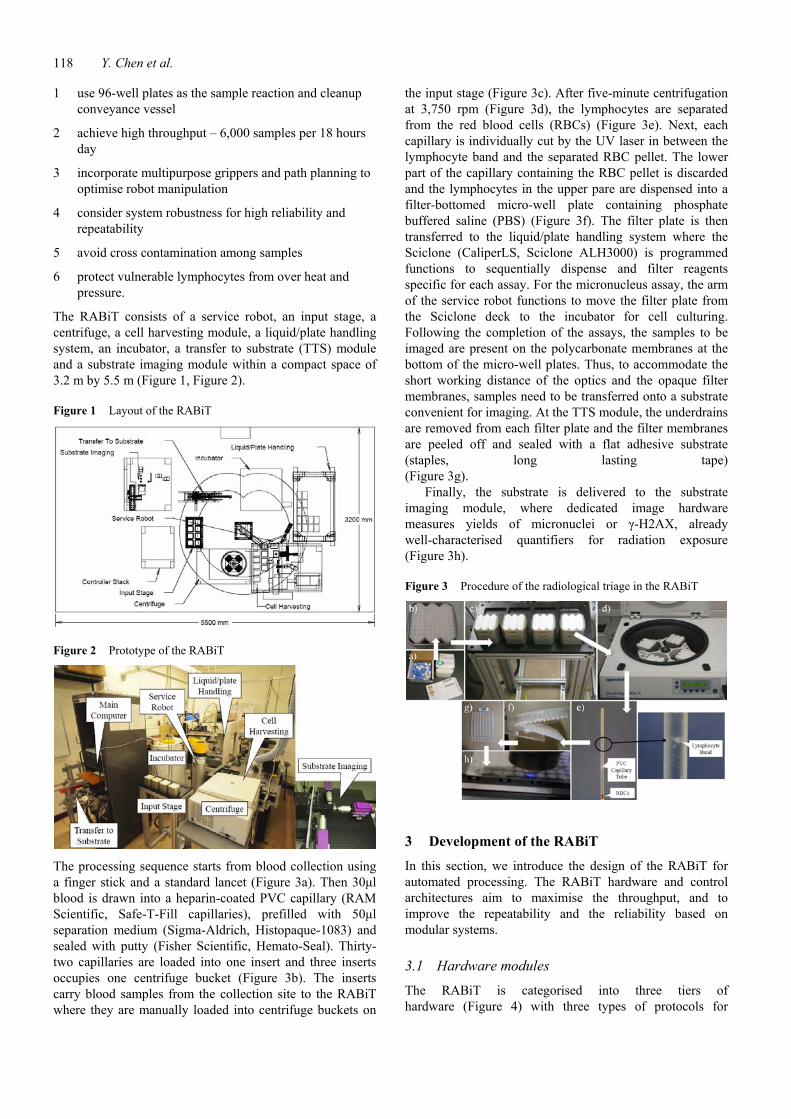
The RABiT consists of a service robot, an input stage, a centrifuge, a cell harvesting module, a liquid/plate handling system, an incubator, a transfer to substrate (TTS) module and a substrate imaging module within a compact space of 3.2 m by 5.5 m (Figure 1, Figure 2).
Figure 1 Layout of the RABiT
Figure 2 Prototype of the RABiT
The processing sequence starts from blood collection using a finger stick and a standard lancet (Figure 3a). Then 30μl blood is drawn into a heparin-coated PVC capillary (RAM Scientific, Safe-T-Fill capillaries), prefilled with 50μl separation medium (Sigma-Aldrich, Histopaque-1083) and sealed with putty (Fisher Scientific, Hemato-Seal). Thirty-two capillaries are loaded into one insert and three inserts occupies one centrifuge bucket (Figure 3b). The inserts carry blood samples from the collection site to the RABiT where they are manually loaded into centrifuge buckets on
the input stage (Figure 3c). After five-minute centrifugation at 3,750 rpm (Figure 3d), the lymphocytes are separated from the red blood cells (RBCs) (Figure 3e). Next, each capillary is individually cut by the UV laser in between the lymphocyte band and the separated RBC pellet. The lower part of the capillary containing the RBC pellet is discarded and the lymphocytes in the upper pare are dispensed into a filter-bottomed micro-well plate containing phosphate buffered saline (PBS) (Figure 3f). The filter plate is then transferred to the liquid/plate handling system where the Sciclone (CaliperLS, Sciclone ALH3000) is programmed functions to sequentially dispense and filter reagents specific for each assay. For the micronucleus assay, the arm of the service robot functions to move the filter plate from the Sciclone deck to the incubator for cell culturing. Following the completion of the assays, the samples to be imaged are present on the polycarbonate membranes at the bottom of the micro-well plates. Thus, to accommodate the short working distance of the optics and the opaque filter membranes, samples need to be transferred onto a substrate convenient for imaging. At the TTS module, the underdrains are removed from each filter plate and the filter membranes are peeled off and sealed with a flat adhesive substrate (staples, long lasting tape) (Figure 3g).
Finally, the substrate is delivered to the substrate imaging module, where dedicated image hardware measures yields of micronuclei or γ-H2AX, already well-characterised quantifiers for radiation exposure (Figure 3h).
Figure 3 Procedure of the radiological triage in the RABiT
3 Development of the RABiT
In this section, we introduce the design of the RABiT for automated processing. The RABiT hardware and control architectures aim to maximise the throughput, and to improve the repeatability and the reliability based on modular systems.
3.1 Hardware modules
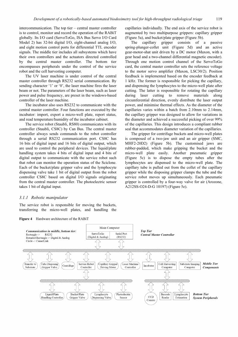
The RABiT is categorised into three tiers of hardware (Figure 4) with three types of protocols for
Development of a robotically-based automated biodosimetry tool for high-throughput radiological triage 119
intercommunication. The top tier – central master controller is to control, monitor and record the operation of the RABiT globally. Its I/O card (ServoToGo, ISA Bus Servo I/O Card Model 2) has 32-bit digital I/O, eight-channel analog I/O, and eight motion control ports for differential TTL encoder signals. The middle tier includes all subsystems which have their own controllers and the actuators directed controlled by the central master controller. The bottom tier encompasses peripherals under the control of the service robot and the cell harvesting computer.
The UV laser machine is under control of the central master controller through RS232 serial communication. By sending character ‘1’ or ‘0’, the laser machine fires the laser beam or not. The parameters of the laser beam, such as laser power and pulse frequency, are preset in the windows-based controller of the laser machine.
The incubator also uses RS232 to communicate with the central master controller. Four functions are executed by the incubator: import, export a micro-well plate, report status, and read temperature/humidity of the incubator cabinet.
The service robot (Staubli, RS80) communicates with its controller (Staubli, CS8C) by Can Bus. The central master controller always sends commands to the robot controller through a serial RS232 communication port. CS8C has 16 bits of digital input and 16 bits of digital output, which are used to control the peripheral devices. The liquid/plate handling system takes 4 bits of digital input and 4 bits of digital output to communicate with the service robot such that robot can monitor the operation status of the Sciclone. Each of the bucket/plate gripper valve and the lymphocyte dispensing valve take 1 bit of digital output from the robot controller CS8C based on digital I/O signals originating from the central master controller. The photoelectric sensor takes 1 bit of digital input.
3.1.1 Robotic manipulator
The service robot is responsible for moving the buckets, transferring the micro-well plates, and handling the
capillaries individually. The end axis of the service robot is augmented by two multipurpose grippers: capillary gripper (Figure 5a), and bucket/plate gripper (Figure 5b).
The capillary gripper consists of a passive spring-plunger-collet unit (Figure 5d) and an active gear-motor-shat unit driven by a DC motor (Maxon, with a gear head and a two-channel differential magnetic encoder). Through one motion control channel of the ServoToGo card, the central master controller sets the reference voltage to the motor servo amplifier (Maxon, LSC30/2). Position feedback is implemented based on the encoder feedback at 1 kHz. The former is responsible for picking the capillary, and dispensing the lymphocytes to the micro-well plate after cutting. The latter is responsible for rotating the capillary during laser cutting to remove materials along circumferential direction, evenly distribute the laser output power, and minimise thermal effects. As the diameter of the capillaries varies within a batch from 2.10mm to 2.14mm, the capillary gripper was designed to allow for variations in the diameter and achieved a successful picking of over 99% of the capillaries. This design introduces a compliant rubber seal that accommodates diameter variation of the capillaries.
The gripper for centrifuge buckets and micro-well plates is composed of a two-jaw unit and an air gripper (SMC, MHF2-20D2) (Figure 5b). The customised jaws are rubber-padded, which make gripping the bucket and the micro-well plate easily. Another pneumatic gripper (Figure 5c) is to dispose the empty tubes after the lymphocytes are dispensed to the micro-well plate. The capillary tube is pulled out from the collet of the capillary gripper while the disposing gripper clamps the tube and the service robot moves up simultaneously. Each pneumatic gripper is controlled by a four-way valve for air (Arozone, A212SS-O24-D-G 10197) (Figure 5e).
Figure 4 Hardware architecture of the RABiT
120 Y. Chen et al.
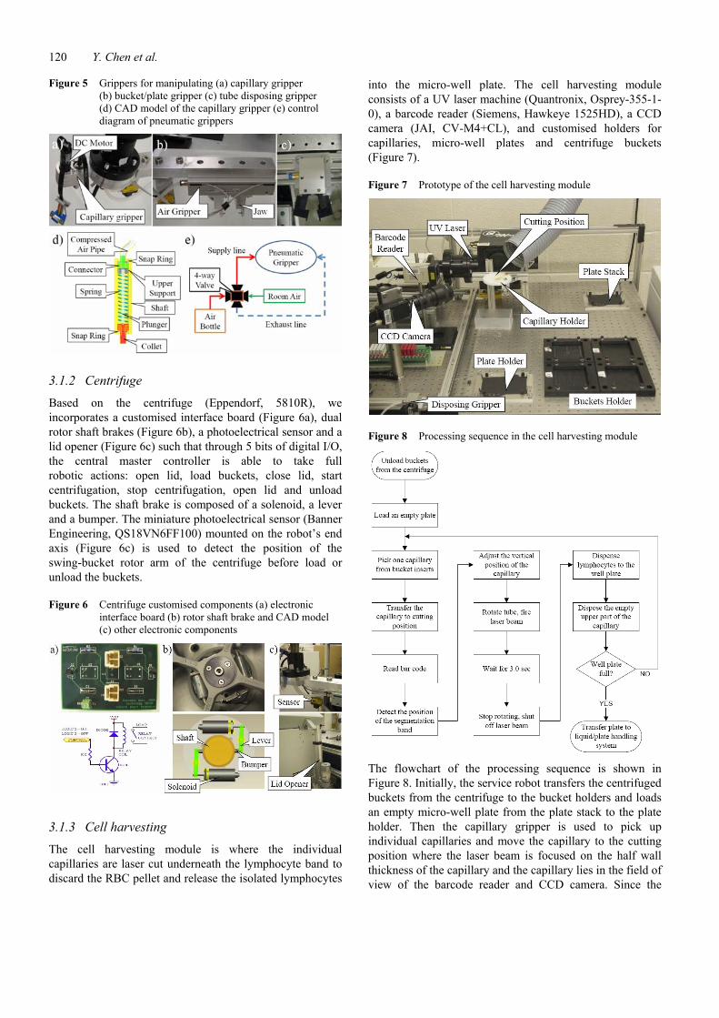
Figure 5 Grippers for manipulating (a) capillary gripper (b) bucket/plate gripper (c) tube disposing gripper (d) CAD model of the capillary gripper (e) control diagram of pneumatic grippers
3.1.2 Centrifuge
Based on the centrifuge (Eppendorf, 5810R), we incorporates a customised interface board (Figure 6a), dual rotor shaft brakes (Figure 6b), a photoelectrical sensor and a lid opener (Figure 6c) such that through 5 bits of digital I/O, the central master controller is able to take full robotic actions: open lid, load buckets, close lid, start centrifugation, stop centrifugation, open lid and unload buckets. The shaft brake is composed of a solenoid, a lever and a bumper. The miniature photoelectrical sensor (Banner Engineering, QS18VN6FF100) mounted on the robot’s end axis (Figure 6c) is used to detect the position of the swing-bucket rotor arm of the centrifuge before load or unload the buckets.
Figure 6 Centrifuge customised components (a) electronic interface board (b) rotor shaft brake and CAD model (c) other electronic components
3.1.3 Cell harvesting
The cell harvesting module is where the individual capillaries are laser cut underneath the lymphocyte band to discard the RBC pellet and release the isolated lymphocytes
into the micro-well plate. The cell harvesting module consists of a UV laser machine (Quantronix, Osprey-355-1-0), a barcode reader (Siemens, Hawkeye 1525HD), a CCD camera (JAI, CV-M4+CL), and customised holders for capillaries, micro-well plates and centrifuge buckets (Figure 7).
Figure 7 Prototype of the cell harvesting module
Figure 8 Processing sequence in the cell harvesting module
The flowchart of the processing sequence is shown in Figure 8. Initially, the service robot transfers the centrifuged buckets from the centrifuge to the bucket holders and loads an empty micro-well plate from the plate stack to the plate holder. Then the capillary gripper is used to pick up individual capillaries and move the capillary to the cutting position where the laser beam is focused on the half wall thickness of the capillary and the capillary lies in the field of view of the barcode reader and CCD camera. Since the
Development of a robotically-based automated biodosimetry tool for high-throughput radiological triage 121
barcode etched on the capillary (Figure 9) is small (2.0 mm × 10.0 mm), reliability of reading barcode is important. To repeat the reading process three times results in a success rate of 95% based on using code 128 for the barcode. After the barcode is identified, the CCD camera interfaces with the cell harvesting computer via a camera link connection and a frame grabber (NI, NI-1426) to capture pictures of the tubes. Then imaging programs based on NI Vision SKD analyse the picture to detect the position of the segmentation band between the culture medium and the RBC. In the following, the service robot moves down or up to align the segmentation band with the laser focal point. Then the robot sends ‘ready’ signal to the central master controller. The central master controller turns on the capillary gripper motor with 40 rpm, and sends ‘1’ to the laser machine to fire the laser beam at the same time. After waiting for 3.0 seconds, the laser beam is shut off and the motor stops. The bottom part of the capillary containing the RBC pellet is disposed, while the upper part is moved above the micro-well plate to dispense the lymphocytes in the micro-well plate. Finally, the empty upper part of the tube is pulled out from the collet of the capillary by the tube disposing gripper. If the micro-well plate is full, the service robot will transfer the plate to the liquid/plate handling module. Otherwise, the cell harvesting module continues to process the following capillary.
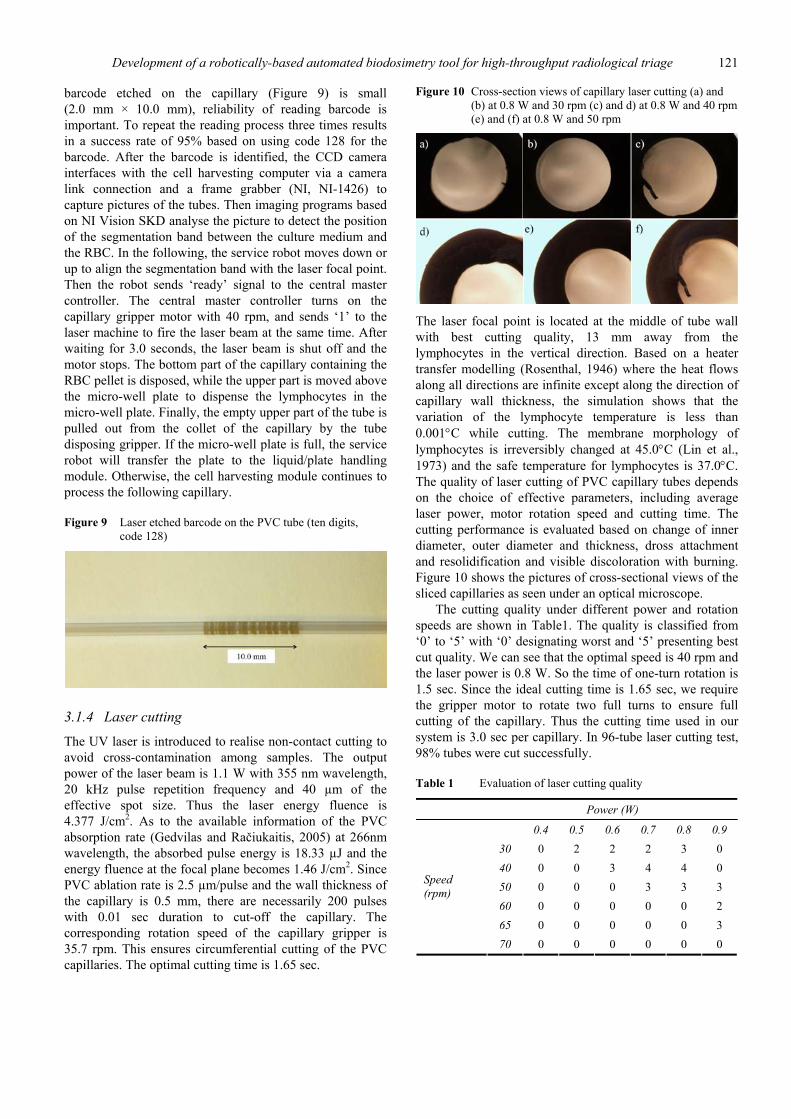
Figure 9 Laser etched barcode on the PVC tube (ten digits, code 128)
3.1.4 Laser cutting
The UV laser is introduced to realise non-contact cutting to avoid cross-contamination among samples. The output power of the laser beam is 1.1 W with 355 nm wavelength, 20 kHz pulse repetition frequency and 40 µm of the effective spot size. Thus the laser energy fluence is 4.377 J/cm2. As to the available information of the PVC absorption rate (Gedvilas and Račiukaitis, 2005) at 266nm wavelength, the absorbed pulse energy is 18.33 µJ and the energy fluence at the focal plane becomes 1.46 J/cm2. Since PVC ablation rate is 2.5 µm/pulse and the wall thickness of the capillary is 0.5 mm, there are necessarily 200 pulses with 0.01 sec duration to cut-off the capillary. The corresponding rotation speed of the capillary gripper is 35.7 rpm. This ensures circumferential cutting of the PVC capillaries. The optimal cutting time is 1.65 sec.
Figure 10 Cross-section views of capillary laser cutting (a) and (b) at 0.8 W and 30 rpm (c) and d) at 0.8 W and 40 rpm (e) and (f) at 0.8 W and 50 rpm
The laser focal point is located at the middle of tube wall with best cutting quality, 13 mm away from the lymphocytes in the vertical direction. Based on a heater transfer modelling (Rosenthal, 1946) where the heat flows along all directions are infinite except along the direction of capillary wall thickness, the simulation shows that the variation of the lymphocyte temperature is less than 0.001°C while cutting. The membrane morphology of lymphocytes is irreversibly changed at 45.0°C (Lin et al., 1973) and the safe temperature for lymphocytes is 37.0°C. The quality of laser cutting of PVC capillary tubes depends on the choice of effective parameters, including average laser power, motor rotation speed and cutting time. The cutting performance is evaluated based on change of inner diameter, outer diameter and thickness, dross attachment and resolidification and visible discoloration with burning. Figure 10 shows the pictures of cross-sectional views of the sliced capillaries as seen under an optical microscope.
The cutting quality under different power and rotation speeds are shown in Table1. The quality is classified from ‘0’ to ‘5’ with ‘0’ designating worst and ‘5’ presenting best cut quality. We can see that the optimal speed is 40 rpm and the laser power is 0.8 W. So the time of one-turn rotation is 1.5 sec. Since the ideal cutting time is 1.65 sec, we require the gripper motor to rotate two full turns to ensure full cutting of the capillary. Thus the cutting time used in our system is 3.0 sec per capillary. In 96-tube laser cutting test, 98% tubes were cut successfully.
Table 1 Evaluation of laser cutting quality
Power (W)
0.4 0.5 0.6 0.7 0.8 0.9 30 0 2 2 2 3 0 40 0 0 3 4 4 0 50 0 0 0 3 3 3 60 0 0 0 0 0 2 65 0 0 0 0 0 3
Speed (rpm)
70 0 0 0 0 0 0
122 Y. Chen et al.
3.1.5 TTS module
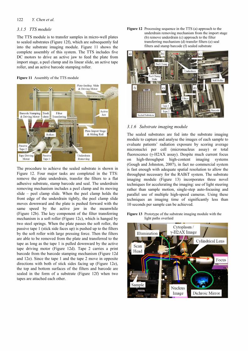
The TTS module is to transfer samples in micro-well plates to sealed substrates (Figure 12f), which are subsequently fed into the substrate imaging module. Figure 11 shows the complete assembly of this system. The TTS includes five DC motors to drive an active jaw to feed the plate from import stage, a peel clamp and its linear slide, an active tape roller, and an active barcode stamping roller.
Figure 11 Assembly of the TTS module
The procedure to achieve the sealed substrate is shown in Figure 12. Four major tasks are completed in the TTS: remove the plate underdrain, transfer the filters to a flat adhesive substrate, stamp barcode and seal. The underdrain removing mechanism includes a peel clamp and its moving slide – peel clamp slide. When the peel clamp holds the front edge of the underdrain tightly, the peel clamp slide moves downward and the plate is pushed forward with the same speed by the active jaw in the meanwhile (Figure 12b). The key component of the filter transferring mechanism is a soft roller (Figure 12c), which is hanged by two steel springs. When the plate passes the soft roller, the passive tape 1 (stick side faces up) is pushed up to the filters by the soft roller with large pressing force. Then the filters are able to be removed from the plate and transferred to the tape as long as the tape 1 is pulled downward by the active tape driving motor (Figure 12d). Tape 2 carries a print barcode from the barcode stamping mechanism (Figure 12d and 12e). Since the tape 1 and the tape 2 move in opposite directions with both of stick sides facing up (Figure 12e), the top and bottom surfaces of the filters and barcode are sealed in the form of a substrate (Figure 12f) when two tapes are attached each other.
Figure 12 Processing sequence in the TTS (a) approach to the underdrain removing mechanism from the import stage (b) remove underdrain (c) approach to the filter transferring mechanism (d) transfer filters (e) seal filters and stamp barcode (f) sealed substrate
3.1.6 Substrate imaging module
The sealed substrates are fed into the substrate imaging module to capture and analyse the images of each sample to evaluate patients’ radiation exposure by scoring average micronuclei per cell (micronucleus assay) or total fluorescence (γ-H2AX assay). Despite much current focus on high-throughput high-content imaging systems (Gough and Johnston, 2007), in fact no commercial system is fast enough with adequate spatial resolution to allow the throughput necessary for the RABiT system. The substrate imaging module (Figure 13) incorporates three novel techniques for accelerating the imaging: use of light steering rather than sample motion, single-step auto-focusing and parallel use of multiple high-speed cameras. Using these techniques an imaging time of significantly less than 10 seconds per sample can be achieved.
Figure 13 Prototype of the substrate imaging module with the light paths overlaid
Development of a robotically-based automated biodosimetry tool for high-throughput radiological triage 123
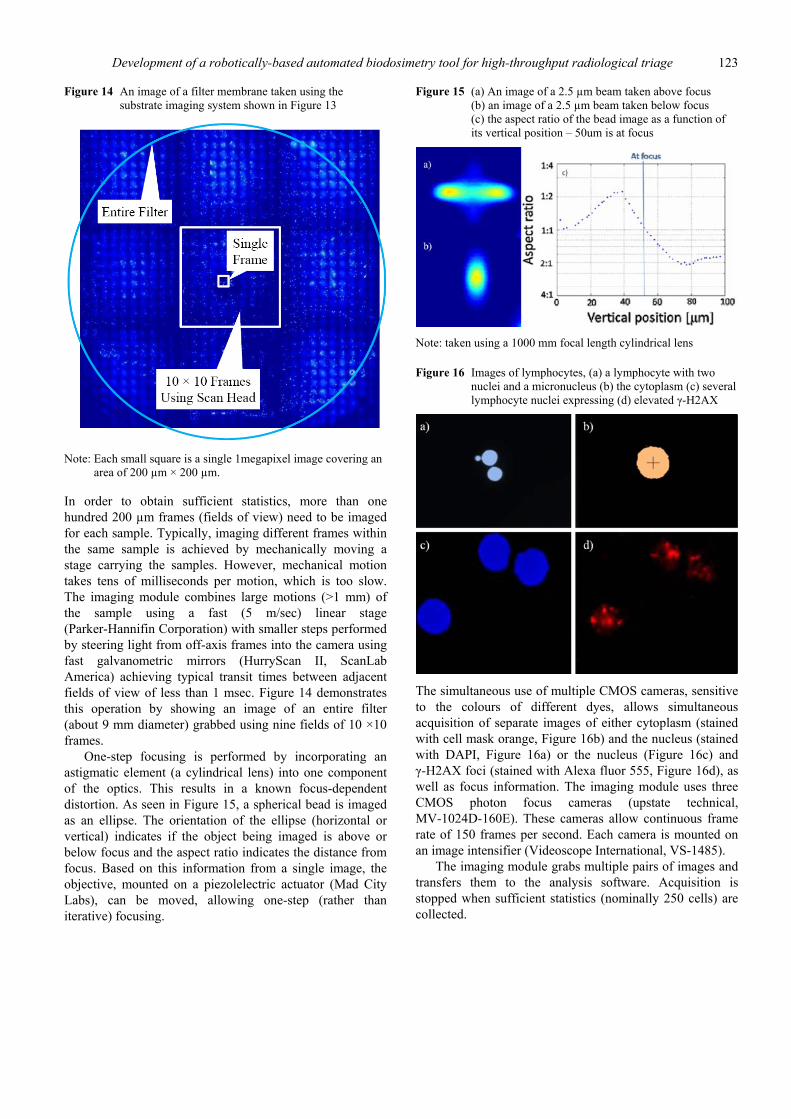
Figure 14 An image of a filter membrane taken using the substrate imaging system shown in Figure 13
Note: Each small square is a single 1megapixel image covering an
area of 200 µm × 200 µm.
In order to obtain sufficient statistics, more than one hundred 200 µm frames (fields of view) need to be imaged for each sample. Typically, imaging different frames within the same sample is achieved by mechanically moving a stage carrying the samples. However, mechanical motion takes tens of milliseconds per motion, which is too slow. The imaging module combines large motions (>1 mm) of the sample using a fast (5 m/sec) linear stage (Parker-Hannifin Corporation) with smaller steps performed by steering light from off-axis frames into the camera using fast galvanometric mirrors (HurryScan II, ScanLab America) achieving typical transit times between adjacent fields of view of less than 1 msec. Figure 14 demonstrates this operation by showing an image of an entire filter (about 9 mm diameter) grabbed using nine fields of 10 ×10 frames.
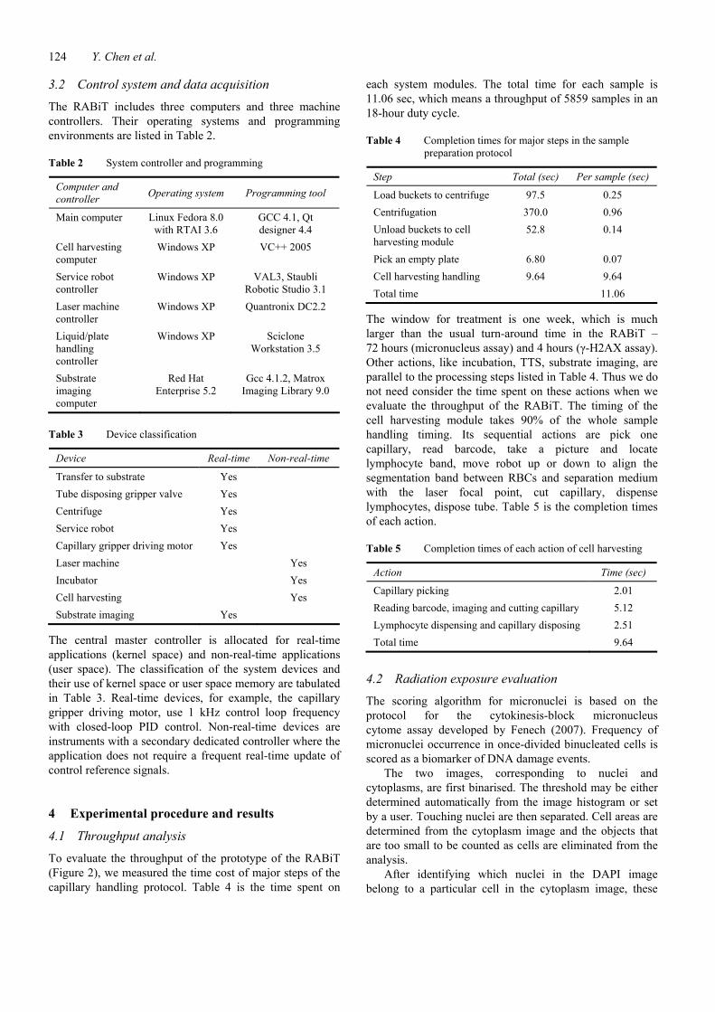
One-step focusing is performed by incorporating an astigmatic element (a cylindrical lens) into one component of the optics. This results in a known focus-dependent distortion. As seen in Figure 15, a spherical bead is imaged as an ellipse. The orientation of the ellipse (horizontal or vertical) indicates if the object being imaged is above or below focus and the aspect ratio indicates the distance from focus. Based on this information from a single image, the objective, mounted on a piezolelectric actuator (Mad City Labs), can be moved, allowing one-step (rather than iterative) focusing.
Figure 15 (a) An image of a 2.5 µm beam taken above focus (b) an image of a 2.5 µm beam taken below focus (c) the aspect ratio of the bead image as a function of its vertical position – 50um is at focus
Note: taken using a 1000 mm focal length cylindrical lens
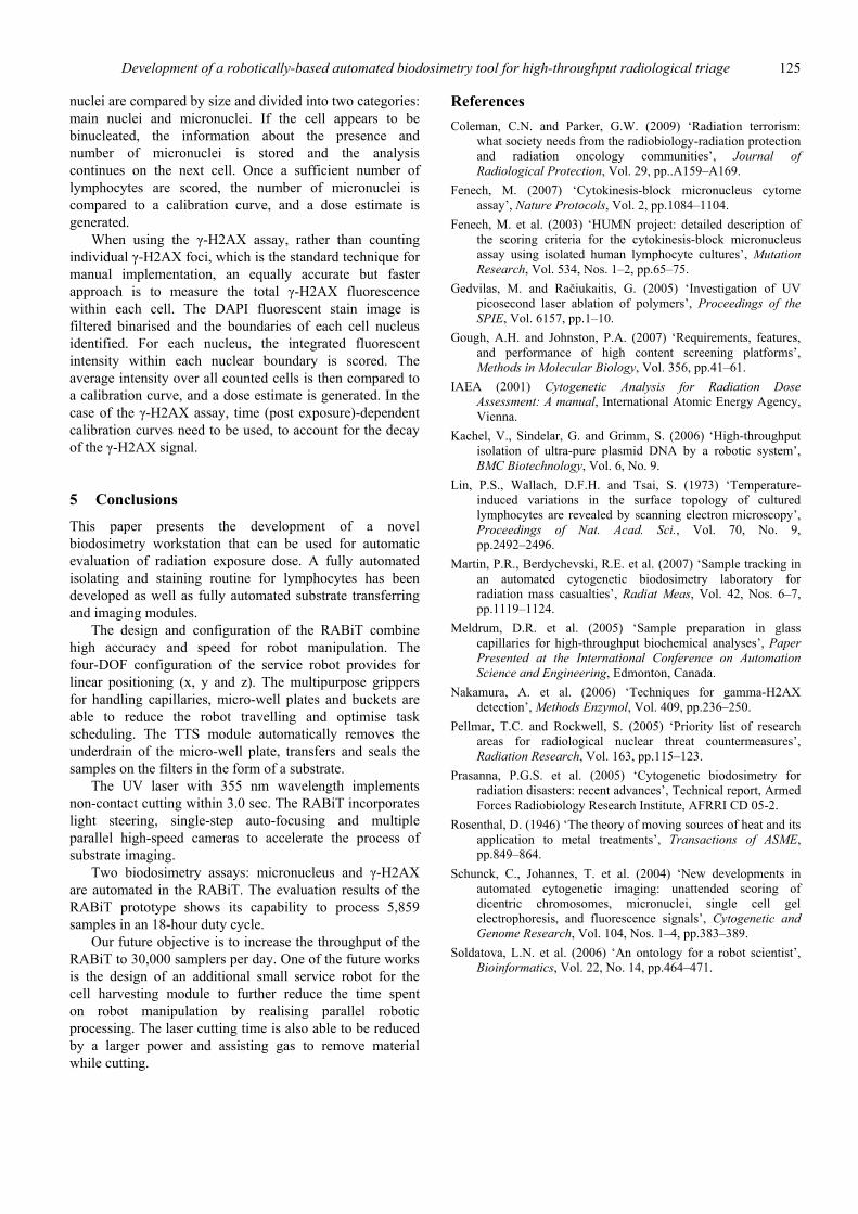
Figure 16 Images of lymphocytes, (a) a lymphocyte with two nuclei and a micronucleus (b) the cytoplasm (c) several lymphocyte nuclei expressing (d) elevated γ-H2AX
The simultaneous use of multiple CMOS cameras, sensitive to the colours of different dyes, allows simultaneous acquisition of separate images of either cytoplasm (stained with cell mask orange, Figure 16b) and the nucleus (stained with DAPI, Figure 16a) or the nucleus (Figure 16c) and γ-H2AX foci (stained with Alexa fluor 555, Figure 16d), as well as focus information. The imaging module uses three CMOS photon focus cameras (upstate technical, MV-1024D-160E). These cameras allow continuous frame rate of 150 frames per second. Each camera is mounted on an image intensifier (Videoscope International, VS-1485).
The imaging module grabs multiple pairs of images and transfers them to the analysis software. Acquisition is stopped when sufficient statistics (nominally 250 cells) are collected.
124 Y. Chen et al.
3.2 Control system and data acquisition
The RABiT includes three computers and three machine controllers. Their operating systems and programming environments are listed in Table 2.
Table 2 System controller and programming
Computer and controller Operating system Programming tool
Main computer Linux Fedora 8.0 with RTAI 3.6
GCC 4.1, Qt designer 4.4
Cell harvesting computer
Windows XP VC++ 2005
Service robot controller
Windows XP VAL3, Staubli Robotic Studio 3.1
Laser machine controller
Windows XP Quantronix DC2.2
Liquid/plate handling controller
Windows XP Sciclone Workstation 3.5
Substrate imaging computer
Red Hat Enterprise 5.2
Gcc 4.1.2, Matrox Imaging Library 9.0
Table 3 Device classification
Device Real-time Non-real-time
Transfer to substrate Yes Tube disposing gripper valve Yes Centrifuge Yes Service robot Yes Capillary gripper driving motor Yes Laser machine Yes Incubator Yes Cell harvesting Yes Substrate imaging Yes
The central master controller is allocated for real-time applications (kernel space) and non-real-time applications (user space). The classification of the system devices and their use of kernel space or user space memory are tabulated in Table 3. Real-time devices, for example, the capillary gripper driving motor, use 1 kHz control loop frequency with closed-loop PID control. Non-real-time devices are instruments with a secondary dedicated controller where the application does not require a frequent real-time update of control reference signals.
4 Experimental procedure and results
4.1 Throughput analysis
To evaluate the throughput of the prototype of the RABiT (Figure 2), we measured the time cost of major steps of the capillary handling protocol. Table 4 is the time spent on
each system modules. The total time for each sample is 11.06 sec, which means a throughput of 5859 samples in an 18-hour duty cycle.
Table 4 Completion times for major steps in the sample preparation protocol
Step Total (sec) Per sample (sec)
Load buckets to centrifuge 97.5 0.25 Centrifugation 370.0 0.96 Unload buckets to cell harvesting module
52.8 0.14
Pick an empty plate 6.80 0.07 Cell harvesting handling 9.64 9.64 Total time 11.06
The window for treatment is one week, which is much larger than the usual turn-around time in the RABiT – 72 hours (micronucleus assay) and 4 hours (γ-H2AX assay). Other actions, like incubation, TTS, substrate imaging, are parallel to the processing steps listed in Table 4. Thus we do not need consider the time spent on these actions when we evaluate the throughput of the RABiT. The timing of the cell harvesting module takes 90% of the whole sample handling timing. Its sequential actions are pick one capillary, read barcode, take a picture and locate lymphocyte band, move robot up or down to align the segmentation band between RBCs and separation medium with the laser focal point, cut capillary, dispense lymphocytes, dispose tube. Table 5 is the completion times of each action.
Table 5 Completion times of each action of cell harvesting
Action Time (sec)
Capillary picking 2.01 Reading barcode, imaging and cutting capillary 5.12 Lymphocyte dispensing and capillary disposing 2.51 Total time 9.64
4.2 Radiation exposure evaluation
The scoring algorithm for micronuclei is based on the protocol for the cytokinesis-block micronucleus cytome assay developed by Fenech (2007). Frequency of micronuclei occurrence in once-divided binucleated cells is scored as a biomarker of DNA damage events.
The two images, corresponding to nuclei and cytoplasms, are first binarised. The threshold may be either determined automatically from the image histogram or set by a user. Touching nuclei are then separated. Cell areas are determined from the cytoplasm image and the objects that are too small to be counted as cells are eliminated from the analysis.
After identifying which nuclei in the DAPI image belong to a particular cell in the cytoplasm image, these
Development of a robotically-based automated biodosimetry tool for high-throughput radiological triage 125
nuclei are compared by size and divided into two categories: main nuclei and micronuclei. If the cell appears to be binucleated, the information about the presence and number of micronuclei is stored and the analysis continues on the next cell. Once a sufficient number of lymphocytes are scored, the number of micronuclei is compared to a calibration curve, and a dose estimate is generated.
When using the γ-H2AX assay, rather than counting individual γ-H2AX foci, which is the standard technique for manual implementation, an equally accurate but faster approach is to measure the total γ-H2AX fluorescence within each cell. The DAPI fluorescent stain image is filtered binarised and the boundaries of each cell nucleus identified. For each nucleus, the integrated fluorescent intensity within each nuclear boundary is scored. The average intensity over all counted cells is then compared to a calibration curve, and a dose estimate is generated. In the case of the γ-H2AX assay, time (post exposure)-dependent calibration curves need to be used, to account for the decay of the γ-H2AX signal.
5 Conclusions
This paper presents the development of a novel biodosimetry workstation that can be used for automatic evaluation of radiation exposure dose. A fully automated isolating and staining routine for lymphocytes has been developed as well as fully automated substrate transferring and imaging modules.
The design and configuration of the RABiT combine high accuracy and speed for robot manipulation. The four-DOF configuration of the service robot provides for linear positioning (x, y and z). The multipurpose grippers for handling capillaries, micro-well plates and buckets are able to reduce the robot travelling and optimise task scheduling. The TTS module automatically removes the underdrain of the micro-well plate, transfers and seals the samples on the filters in the form of a substrate.
The UV laser with 355 nm wavelength implements non-contact cutting within 3.0 sec. The RABiT incorporates light steering, single-step auto-focusing and multiple parallel high-speed cameras to accelerate the process of substrate imaging.
Two biodosimetry assays: micronucleus and γ-H2AX are automated in the RABiT. The evaluation results of the RABiT prototype shows its capability to process 5,859 samples in an 18-hour duty cycle.
Our future objective is to increase the throughput of the RABiT to 30,000 samplers per day. One of the future works is the design of an additional small service robot for the cell harvesting module to further reduce the time spent on robot manipulation by realising parallel robotic processing. The laser cutting time is also able to be reduced by a larger power and assisting gas to remove material while cutting.
References Coleman, C.N. and Parker, G.W. (2009) ‘Radiation terrorism:
what society needs from the radiobiology-radiation protection and radiation oncology communities’, Journal of Radiological Protection, Vol. 29, pp..A159–A169.
Fenech, M. (2007) ‘Cytokinesis-block micronucleus cytome assay’, Nature Protocols, Vol. 2, pp.1084–1104.
Fenech, M. et al. (2003) ‘HUMN project: detailed description of the scoring criteria for the cytokinesis-block micronucleus assay using isolated human lymphocyte cultures’, Mutation Research, Vol. 534, Nos. 1–2, pp.65–75.
Gedvilas, M. and Račiukaitis, G. (2005) ‘Investigation of UV picosecond laser ablation of polymers’, Proceedings of the SPIE, Vol. 6157, pp.1–10.
Gough, A.H. and Johnston, P.A. (2007) ‘Requirements, features, and performance of high content screening platforms’, Methods in Molecular Biology, Vol. 356, pp.41–61.
IAEA (2001) Cytogenetic Analysis for Radiation Dose Assessment: A manual, International Atomic Energy Agency, Vienna.
Kachel, V., Sindelar, G. and Grimm, S. (2006) ‘High-throughput isolation of ultra-pure plasmid DNA by a robotic system’, BMC Biotechnology, Vol. 6, No. 9.
Lin, P.S., Wallach, D.F.H. and Tsai, S. (1973) ‘Temperature-induced variations in the surface topology of cultured lymphocytes are revealed by scanning electron microscopy’, Proceedings of Nat. Acad. Sci., Vol. 70, No. 9, pp.2492–2496.
Martin, P.R., Berdychevski, R.E. et al. (2007) ‘Sample tracking in an automated cytogenetic biodosimetry laboratory for radiation mass casualties’, Radiat Meas, Vol. 42, Nos. 6–7, pp.1119–1124.
Meldrum, D.R. et al. (2005) ‘Sample preparation in glass capillaries for high-throughput biochemical analyses’, Paper Presented at the International Conference on Automation Science and Engineering, Edmonton, Canada.
Nakamura, A. et al. (2006) ‘Techniques for gamma-H2AX detection’, Methods Enzymol, Vol. 409, pp.236–250.
Pellmar, T.C. and Rockwell, S. (2005) ‘Priority list of research areas for radiological nuclear threat countermeasures’, Radiation Research, Vol. 163, pp.115–123.
Prasanna, P.G.S. et al. (2005) ‘Cytogenetic biodosimetry for radiation disasters: recent advances’, Technical report, Armed Forces Radiobiology Research Institute, AFRRI CD 05-2.
Rosenthal, D. (1946) ‘The theory of moving sources of heat and its application to metal treatments’, Transactions of ASME, pp.849–864.
Schunck, C., Johannes, T. et al. (2004) ‘New developments in automated cytogenetic imaging: unattended scoring of dicentric chromosomes, micronuclei, single cell gel electrophoresis, and fluorescence signals’, Cytogenetic and Genome Research, Vol. 104, Nos. 1–4, pp.383–389.
Soldatova, L.N. et al. (2006) ‘An ontology for a robot scientist’, Bioinformatics, Vol. 22, No. 14, pp.464–471.