Development of a prototype 15 MeV Electron Linac · Figure1: 15 MeV linac tube made at SAMEER,...
3
DEVELOPMENT OF A PROTOTYPE 15 MeV ELECTRON LINAC Tanuja S Dixit * , Sharad T Chavan, Ramamoorthy Krishnan, Chandrakant S Nainwad, Sanjay N Pethe, Kiran A Thakur, Tapeshwar Tiwari, Mandar M Vidwans(SAMEER), Abhay Deshpande (SAMEER, GUAS) Society for Applied Microwave Electronic Engineering and Research (SAMEER), R&D Lab of Gov. of India, IIT Campus, Powai, Mumbai 400 076, India Graduate University for Advanced Studies (GUAS), High Energy Accelerator Research Organization (KEK), Ibaraki, Tsukuba, Japan Abstract A successful development of a 6 MeV electron radiotherapy machine at SAMEER, India was reported earlier. Now a 15 MeV electron linac prototype is designed, developed and tested at our site. We have measured a beam current of 80 mA at the X-ray target attached to the linac. Energy gained by electrons in a cavity chain of about 1.2 m length is measured to be more than 15 MeV using a 6 MW klystron power source. An RF window capable of handling 12kW average power is attached to the linac tube and it is cooled by water. The final linac parameters measured were at par with the designed values. A high voltage modulator and control console for the linac are designed and developed in house. This paper will describe key aspects of the design and development process of the complete system. Also future applications are planned like-dual energy dual mode linac for radiotherapy, cargo scanning system and compact Compton X-ray source using this technology is briefed in this paper. INTRODUCTION We have already reported the developmental work of 6 MeV linac tube with the detail design parameters and test results [1]. Based on the same design, SAMEER has developed a 15 MeV S-band standing wave side coupled linear accelerator (linac). The SAMEER 6 MeV linac is already mounted on a gantry system and is functional as a radiation oncology system at two hospitals in India. The linac has already delivered dose to 30,000 patient treatments. We hope to have a successful technology transfer in near future so that our basic work is taken up by industry for production. The 15 MeV linac is 1.2 m long side coupled π/2 mode standing wave structure. The main parameters of the linac structures made are tabulated in Table 1. The design and development work was to achieve 80 mA peak current at 15 MeV energy as compared to 140 mA peak current at 6 MeV energy [1]. A 6 MW Klystron is used as an RF power source at 2.998 GHz frequency for the 15 MeV linac tube. -------------------------------------------------------------------- *[email protected] Tel: +91-22-2572-7231 The linac tube was successfully tested on the test bench and gives a high current of 80 mA with 6 μs pulse width. The repetition rate was 166 Hz. Table 1: Parameters for Linac tubes made at SAMEER Parameter Value Energy 6 15 MeV Frequency 2998 2998 MHz Peak current 140 78 mA Input Power 2.4 6 MW(peak) Length of Tube 32 112 cms LINAC DESIGN The basic design parameters of linac tube are given in Table 1 [2]. The linac operates in π/2 mode, hence every alternate cavity has no accelerating fields and plays role in coupling the power only. These coupling cells are moved out of main axis of linac thus making the linac a side coupled structure. The π/2 operation mode is widely reported in literature [3] [4]. The bi-periodic chain of coupled cells with the coupling cell taken off-axis to make the side coupled structure has many advantages. In the side coupled structure, the beam experiences π-mode-like fields and hence we get the advantage of high shunt impedance of π mode. Inherently, π/2 mode is much stable over temperature variations and the geometrical tolerances are less stringent as compared to π mode. These structures are therefore very popular in making moderately high current, stable beam linac structures, mainly used for medical applications. The structure design is very complicated from fabrication point of view but we have successfully established the fabrication, tuning and measurement procedure for the linac. All components are fabricated and brazed in-house at SAMEER campus in India. The 15 MeV linac structure contains 24 accelerating cells and 23 coupling cells. The first two and half cells of linac tube are the buncher cavities for bunching the beam from the dc gun. Fig. 1 shows the brazed linac tube. The design and measured parameters are given in Table 2. Proceedings of IPAC’10, Kyoto, Japan MOPEA050 08 Applications of Accelerators, Technology Transfer and Industrial Relations U05 Applications, Other 187
Transcript of Development of a prototype 15 MeV Electron Linac · Figure1: 15 MeV linac tube made at SAMEER,...

DEVELOPMENT OF A PROTOTYPE 15 MeV ELECTRON LINAC
Tanuja S Dixit*, Sharad T Chavan, Ramamoorthy Krishnan, Chandrakant S Nainwad, Sanjay N Pethe, Kiran A Thakur, Tapeshwar Tiwari, Mandar M Vidwans(SAMEER), Abhay Deshpande
(SAMEER, GUAS)
Society for Applied Microwave Electronic Engineering and Research (SAMEER), R&D Lab of Gov. of India, IIT Campus, Powai, Mumbai 400 076, India
Graduate University for Advanced Studies (GUAS), High Energy Accelerator Research Organization (KEK), Ibaraki, Tsukuba, Japan
Abstract A successful development of a 6 MeV electron
radiotherapy machine at SAMEER, India was reported earlier. Now a 15 MeV electron linac prototype is designed, developed and tested at our site. We have measured a beam current of 80 mA at the X-ray target attached to the linac. Energy gained by electrons in a cavity chain of about 1.2 m length is measured to be more than 15 MeV using a 6 MW klystron power source. An RF window capable of handling 12kW average power is attached to the linac tube and it is cooled by water. The final linac parameters measured were at par with the designed values. A high voltage modulator and control console for the linac are designed and developed in house. This paper will describe key aspects of the design and development process of the complete system. Also future applications are planned like-dual energy dual mode linac for radiotherapy, cargo scanning system and compact Compton X-ray source using this technology is briefed in this paper.
INTRODUCTION We have already reported the developmental work of 6
MeV linac tube with the detail design parameters and test results [1]. Based on the same design, SAMEER has developed a 15 MeV S-band standing wave side coupled linear accelerator (linac). The SAMEER 6 MeV linac is already mounted on a gantry system and is functional as a radiation oncology system at two hospitals in India. The linac has already delivered dose to 30,000 patient treatments. We hope to have a successful technology transfer in near future so that our basic work is taken up by industry for production. The 15 MeV linac is 1.2 m long side coupled π/2 mode standing wave structure. The main parameters of the linac structures made are tabulated in Table 1. The design and development work was to achieve 80 mA peak current at 15 MeV energy as compared to 140 mA peak current at 6 MeV energy [1]. A 6 MW Klystron is used as an RF power source at 2.998 GHz frequency for the 15 MeV linac tube. --------------------------------------------------------------------
*[email protected] Tel: +91-22-2572-7231
The linac tube was successfully tested on the test bench and gives a high current of 80 mA with 6 μs pulse width. The repetition rate was 166 Hz.
Table 1: Parameters for Linac tubes made at SAMEER Parameter Value Energy 6 15 MeV Frequency 2998 2998 MHz Peak current 140 78 mA Input Power 2.4 6 MW(peak) Length of Tube 32 112 cms
LINAC DESIGN The basic design parameters of linac tube are given in
Table 1 [2]. The linac operates in π/2 mode, hence every alternate cavity has no accelerating fields and plays role in coupling the power only. These coupling cells are moved out of main axis of linac thus making the linac a side coupled structure.
The π/2 operation mode is widely reported in literature [3] [4]. The bi-periodic chain of coupled cells with the coupling cell taken off-axis to make the side coupled structure has many advantages. In the side coupled structure, the beam experiences π-mode-like fields and hence we get the advantage of high shunt impedance of π mode. Inherently, π/2 mode is much stable over temperature variations and the geometrical tolerances are less stringent as compared to π mode. These structures are therefore very popular in making moderately high current, stable beam linac structures, mainly used for medical applications. The structure design is very complicated from fabrication point of view but we have successfully established the fabrication, tuning and measurement procedure for the linac. All components are fabricated and brazed in-house at SAMEER campus in India. The 15 MeV linac structure contains 24 accelerating cells and 23 coupling cells. The first two and half cells of linac tube are the buncher cavities for bunching the beam from the dc gun. Fig. 1 shows the brazed linac tube. The design and measured parameters are given in Table 2.
Proceedings of IPAC’10, Kyoto, Japan MOPEA050
08 Applications of Accelerators, Technology Transfer and Industrial Relations
U05 Applications, Other 187
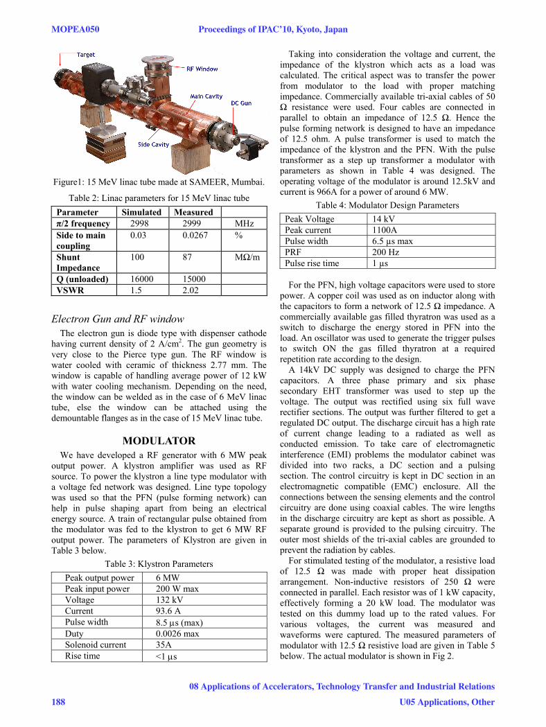
Figure1: 15 MeV linac tube made at SAMEER, Mumbai.
Table 2: Linac parameters for 15 MeV linac tube Parameter Simulated Measured π/2 frequency 2998 2999 MHz Side to main coupling
0.03 0.0267 %
Shunt Impedance
100 87 MΩ/m
Q (unloaded) 16000 15000 VSWR 1.5 2.02
Electron Gun and RF window The electron gun is diode type with dispenser cathode
having current density of 2 A/cm2. The gun geometry is very close to the Pierce type gun. The RF window is water cooled with ceramic of thickness 2.77 mm. The window is capable of handling average power of 12 kW with water cooling mechanism. Depending on the need, the window can be welded as in the case of 6 MeV linac tube, else the window can be attached using the demountable flanges as in the case of 15 MeV linac tube.
MODULATOR We have developed a RF generator with 6 MW peak
output power. A klystron amplifier was used as RF source. To power the klystron a line type modulator with a voltage fed network was designed. Line type topology was used so that the PFN (pulse forming network) can help in pulse shaping apart from being an electrical energy source. A train of rectangular pulse obtained from the modulator was fed to the klystron to get 6 MW RF output power. The parameters of Klystron are given in Table 3 below.
Table 3: Klystron Parameters Peak output power 6 MW Peak input power 200 W max Voltage 132 kV Current 93.6 A Pulse width 8.5 μs (max) Duty 0.0026 max Solenoid current 35A Rise time <1 μs
Taking into consideration the voltage and current, the impedance of the klystron which acts as a load was calculated. The critical aspect was to transfer the power from modulator to the load with proper matching impedance. Commercially available tri-axial cables of 50 Ω resistance were used. Four cables are connected in parallel to obtain an impedance of 12.5 Ω. Hence the pulse forming network is designed to have an impedance of 12.5 ohm. A pulse transformer is used to match the impedance of the klystron and the PFN. With the pulse transformer as a step up transformer a modulator with parameters as shown in Table 4 was designed. The operating voltage of the modulator is around 12.5kV and current is 966A for a power of around 6 MW.
Table 4: Modulator Design Parameters Peak Voltage 14 kV Peak current 1100A Pulse width 6.5 µs max PRF 200 Hz Pulse rise time 1 µs
For the PFN, high voltage capacitors were used to store
power. A copper coil was used as on inductor along with the capacitors to form a network of 12.5 Ω impedance. A commercially available gas filled thyratron was used as a switch to discharge the energy stored in PFN into the load. An oscillator was used to generate the trigger pulses to switch ON the gas filled thyratron at a required repetition rate according to the design.
A 14kV DC supply was designed to charge the PFN capacitors. A three phase primary and six phase secondary EHT transformer was used to step up the voltage. The output was rectified using six full wave rectifier sections. The output was further filtered to get a regulated DC output. The discharge circuit has a high rate of current change leading to a radiated as well as conducted emission. To take care of electromagnetic interference (EMI) problems the modulator cabinet was divided into two racks, a DC section and a pulsing section. The control circuitry is kept in DC section in an electromagnetic compatible (EMC) enclosure. All the connections between the sensing elements and the control circuitry are done using coaxial cables. The wire lengths in the discharge circuitry are kept as short as possible. A separate ground is provided to the pulsing circuitry. The outer most shields of the tri-axial cables are grounded to prevent the radiation by cables.
For stimulated testing of the modulator, a resistive load of 12.5 Ω was made with proper heat dissipation arrangement. Non-inductive resistors of 250 Ω were connected in parallel. Each resistor was of 1 kW capacity, effectively forming a 20 kW load. The modulator was tested on this dummy load up to the rated values. For various voltages, the current was measured and waveforms were captured. The measured parameters of modulator with 12.5 Ω resistive load are given in Table 5 below. The actual modulator is shown in Fig 2.
MOPEA050 Proceedings of IPAC’10, Kyoto, Japan
188
08 Applications of Accelerators, Technology Transfer and Industrial Relations
U05 Applications, Other

Figure 2: Modulator for 15 MeV Linac system.
Table 5: Test results of Modulator. Peak Voltage 13.5 kV Peak current 1140A Pulse width 6.5 µs max PRF 200 Hz Pulse rise time 1 µs Further the modulator was connected to the klystron via
the pulse transformer. The klystron output was connected to the load. RF power was fed to the klystron from the RF driver for amplification. The output power measurements were done. The output voltage and current waveforms were observed at various repetition rates. Input power of the klystron was varied in steps and the output power was measured at different modulator voltages. At 60 W input power to klystron amplifier, the peak power output was measured 6 MW. The reflected waveform as observed on the coupler and klystron current waveform is shown in Fig.3.
The modulator output pulse width measured is well in agreement with the designed value. The impedance matching between the modulator and the klystron source was achieved. The power measurements are well in agreement with the designed values. The high power pulsed modulator developed is operating satisfactorily.
CONCLUSIONS We successfully developed 15 MeV Linac system. The
π/2 mode linac was tuned to desired frequency and the coupling between waveguide to linac was set around 2.02 (VSWR). A 12 kW average power RF window was designed and tested to hold vacuum of the order of 10-9 torr on linac side and high pressure SF6 at 32 psi on circulator side with a VSWR of 1.03 for RF transmission. A high power modulator was designed and developed. The modulator is capable of driving Klystron to deliver
Figure 3: Klystron current and reflected waveform from directional coupler.
6 MW peak power with 6 μs pulse width at 200 Hz rep rate to the linac. The linac has adequate water cooling to remove heat from the linac as well as the target area. A water cooled Tungsten target was designed and tested in our linac. At maximum rating the linac is capable of delivering 80 mA peak current to the target. This linac being prototype, the dose obtained is very good and we can scale down the parameters to get dose suitable for actual patient treatment. The linac tube is long therefore cannot be mounted on the gantry in vertical position. So design of a beam bending chamber to bend the beam in 270° and then to strike the target material is undergoing. At present we plan to use four jaw collimator for patient treatment. For future applications, a multi leaf collimator system design for precision dose delivery is required. We conclude that the prototype is successfully completed and is ready for further work. With the expertise that now we have developed in making linac tubes, we plan to launch new activities like dual energy dual mode linac for radiotherapy, cargo scanning system, Inverse Compton X-ray source based on π/2 mode linac. Efforts are also focused to make high gradient S-band structures to reduce the length of linac tube.
REFERENCES [1] R.Krishnan et. al. "S band linac tube developmental
work in SAMEER", FR5REP083, PAC09, Vancouver, Canada.
[2] Abhay Deshpande, Tanuja Dixit et al. “S-band linac-based X-ray source with π/2-mode electron linac” Nuclear Instruments and Methods in Physics Research A (2010), doi:10.1016/j.nima.2010.02.023.
[3] D. A. Nagle, Knapp and Knapp, Rev Sci Intru, 38(11), 1967, pp 1583-1587
[4] K.Irie et al, Jap J. Ap.p. Phys, 12(2), 1973, 277.
Proceedings of IPAC’10, Kyoto, Japan MOPEA050
08 Applications of Accelerators, Technology Transfer and Industrial Relations
U05 Applications, Other 189