
Development of a New 3D Nonwoven for Automotive Trim Applications
26
18 Development of a New 3D Nonwoven for Automotive Trim Applications Nicole Njeugna 1 , Laurence Schacher 1 , Dominique C. Adolphe 1 , Jean-Baptiste Schaffhauser 2 and Patrick Strehle 2 1 Laboratoire de Physique et Mécanique Textiles EAC 7189 CNRS, University of Haute Alsace 2 N. Schlumberger France 1. Introduction Nowadays, the automotive manufacturers have to take into account the legislation on End Life Vehicle (ELV), especially the European Directive 2000/ 53/ CE which constraints all automotive products to be at 85% recyclable and at 95% reuseable by January 2015 (EU Directive, 2000). The automotive multilayer structure used for automotive trim applications, fabric (PET) / foam (PU) / backing fabric (PA), does not offer ability for recycling or reusing and the question that has to be asked is “ Could the PU foam used in the automotive trim applications be replaced by a mono component spacer material?” One answer is to propose an eco-friendly solution presenting a mono material product. Moreover, this new product has to answer to the automotive specifications in terms of lightness, formability and cost. Some solutions for PU foam replacement have been proposed, such as spacer fabrics presenting a vertical orientation of the yarns (weaving and knitting technologies) or a vertical orientation of the fibers (nonwoven technology). The vertical orientation of the fibers will improve the mechanical properties of the fabric especially for the compressional ones. Critical analyses between the different 3D textiles technologies show that the nonwoven technology provides the best industrial solution in terms of cost and productivity. Regarding the 3D nonwoven products, the “on the market” ones present drawbacks that do not allow them to answer positively to the initial question concerning the replacement of the PU foam. Indeed, the structure of these 3D nonwovens does not present a perfect vertical orientation of the fibres (Njeugna, 2009). Consequently, these products do not offer a maximal resilience in terms of compression properties. In this context, a French consortium composed of research laboratory (LPMT as project leader), textile industrialists (N. Schlumberger, AMDES, Protechnic, Landolt, Dollfus & Müller, Rhenoflex Dreyer), textile technical centre (IFTH 1 ) has been formed to develop an eco-friendly 3D nonwoven which would not present the previous drawbacks. This new 3D nonwoven could be used to replace polyurethane foam classically used in automotive trim applications. This consortium has been supported by the Alsace Textile Cluster, the Alsace 1 IFTH : Institut Français du Textile Habillement, www.ifth.org www.intechopen.com
Transcript of Development of a New 3D Nonwoven for Automotive Trim Applications

18
Development of a New 3D Nonwoven for Automotive Trim Applications
Nicole Njeugna1, Laurence Schacher1, Dominique C. Adolphe1,
Jean-Baptiste Schaffhauser2 and Patrick Strehle2 1Laboratoire de Physique et Mécanique Textiles EAC 7189 CNRS,
University of Haute Alsace 2N. Schlumberger
France
1. Introduction
Nowadays, the automotive manufacturers have to take into account the legislation on End
Life Vehicle (ELV), especially the European Directive 2000/ 53/ CE which constraints all
automotive products to be at 85% recyclable and at 95% reuseable by January 2015
(EU Directive, 2000). The automotive multilayer structure used for automotive trim
applications, fabric (PET) / foam (PU) / backing fabric (PA), does not offer ability for
recycling or reusing and the question that has to be asked is “Could the PU foam used in the
automotive trim applications be replaced by a mono component spacer material?” One
answer is to propose an eco-friendly solution presenting a mono material product.
Moreover, this new product has to answer to the automotive specifications in terms of
lightness, formability and cost. Some solutions for PU foam replacement have been
proposed, such as spacer fabrics presenting a vertical orientation of the yarns (weaving and
knitting technologies) or a vertical orientation of the fibers (nonwoven technology). The
vertical orientation of the fibers will improve the mechanical properties of the fabric
especially for the compressional ones. Critical analyses between the different 3D textiles
technologies show that the nonwoven technology provides the best industrial solution in
terms of cost and productivity. Regarding the 3D nonwoven products, the “on the market”
ones present drawbacks that do not allow them to answer positively to the initial question
concerning the replacement of the PU foam. Indeed, the structure of these 3D nonwovens
does not present a perfect vertical orientation of the fibres (Njeugna, 2009). Consequently,
these products do not offer a maximal resilience in terms of compression properties.
In this context, a French consortium composed of research laboratory (LPMT as project
leader), textile industrialists (N. Schlumberger, AMDES, Protechnic, Landolt, Dollfus &
Müller, Rhenoflex Dreyer), textile technical centre (IFTH1) has been formed to develop an
eco-friendly 3D nonwoven which would not present the previous drawbacks. This new 3D
nonwoven could be used to replace polyurethane foam classically used in automotive trim
applications. This consortium has been supported by the Alsace Textile Cluster, the Alsace
1 IFTH : Institut Français du Textile Habillement, www.ifth.org
www.intechopen.com

New Trends and Developments in Automotive Industry
324
Region and the “Département du Haut-Rhin” . This collaborative research project, named
VERTILAP, has been labelled by the French competitiveness cluster “Vehicle of the Future”
in 2006 and the French ”Fibres Innovative cluster” in 2009.
This chapter will present the state of the art of the technical textiles classically used as
automotive trim such as seat and door panel upholsteries. The manufacturing processes and
the specifications of these automotive multilayer fabrics will be exposed. Their methods of
characterization will be presented. The description of the PU foam and the problem it raises
will be highlighted. The state of the art of the existing 3D textiles for PU foam substitution,
processes and products will be detailed. This chapter will also present the principle of the
VERTILAP® process and the experimental procedure which has been used to realise the
VERTILAP® products. Methods and tools of characterization that have been developed in
order to evaluate the physical and compression properties of this new material will be
exposed. The comparative study that has been carried out between the VERTILAP®
products and the classical automotive fabrics in the case of monolayer and multilayer
structures will be detailed too.
2. Bibliographical study
2.1 Textiles used for automotive upholsteries The textile fabric is an interesting material for automotive industry regarding its
functionality (lightness, acoustic and thermal insulation, etc.) and its mechanical behaviour.
It is used in three main components of the car: the interior, the engine compartment and the
pneumatics (Némoz, 1999). The car interior has significantly evolved since the last decade
and has become one of the key elements of the customer purchasing. Nowadays, the
consumer pays special attention to the environment inside the car. Therefore, the factors of
comfort, beauty (harmony of colours and designs) and security have become main factors in
the sale of a vehicle. Since 90s, the car manufacturers have significantly increased the use of
textiles in the interior trim. Actually, the weight of an European vehicle includes 11 kg of
textiles on a surface of 16 m². Textile fabrics used for the seat are employed on a visible
surface of 3.8 m² while those used for the door panel are employed on a visible surface of
1.7 m². (DGE, 2005), (Fung & Hardcastle, 2001)
This study aims to present the state of the art on the technical textiles classically used as seat
and door panel upholstery in the car interior. Examples of automotive seat and door panel
are illustrated on Fig. 1 and 2.
(a) (b) (c)
Fig. 1. Automotive seat: structure (a), foam cushion (b), automotive complex (c)
www.intechopen.com

Development of a New 3D Nonwoven for Automotive Trim Applications
325
Fig. 2. Example of an integral door panel
Different methods of construction of seat and door panel are listed in the literature review
(Fung & Hardcastle, 2001). The seat trimming can be realised thanks to the “ foam in fabric”
technique, the direct joining technique or the injection moulding technique. The “ foam in
fabric” technique consists on slipping the automotive complex on the seat cushion. The
direct joining technique consists on spraying a solvent adhesive either on the automotive
complex, either on the foam cushion or both in order to link them together. In the case of
injection moulding technique, the foam is directly injected into the automotive complex
previously placed in a mould. Textile-insert low pressure moulding, using polypropylene
resin, is used to produce a covered door panel in a single operation.
The automotive complex (Fig. 3) is usually composed of a decorative fabric made of
polyester, polyurethane foam and a backing fabric made of polyamide. The polyurethane
foam is generally a thin layer with a thickness between 2 mm to 8 mm and a mass per unit
area of about 200 g/ m². The foam gives the flexibility and the soft touch while the backing
fabric gives the dimensional stability to the multilayer structure. In case of “ foam in fabric”
technique, the backing fabric contributes to facilitate the slippage of the cover laminate on
the foam cushion. The backing fabric is not necessary used in the case of door panel
upholstery. (Caudron, 2003), (ITF, 1990)
Fig. 3. The automotive complex
The automotive complex can be produced thanks to different techniques (Hopkins, 1995).
Some of them are well known as the flame lamination and the dry lamination processes. In
the flame lamination process (Fig. 4), the textile layers and the PU foam are linked together
using the PU foam as an adhesive. This process has the disadvantage to generate toxic gases.
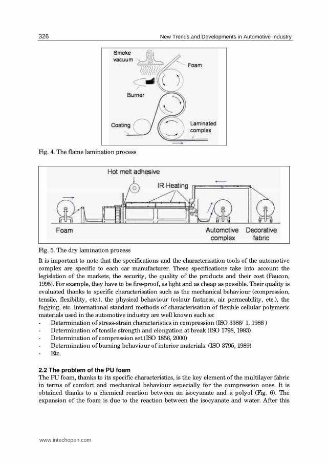
The maximal speed can reached 25 m/ min. In the dry lamination process (Fig. 5), hot melt
adhesives (web, film, powder) are used to bind the textile layers and the PU foam. This
process does not generate toxic gases as the flame lamination one but its main drawback is
its cost. The maximal speed can reached 16 m/ min.
www.intechopen.com
New Trends and Developments in Automotive Industry
326
Fig. 4. The flame lamination process
Fig. 5. The dry lamination process
It is important to note that the specifications and the characterisation tools of the automotive
complex are specific to each car manufacturer. These specifications take into account the
legislation of the markets, the security, the quality of the products and their cost (Faucon,
1995). For example, they have to be fire-proof, as light and as cheap as possible. Their quality is
evaluated thanks to specific characterisation such as the mechanical behaviour (compression,
tensile, flexibility, etc.), the physical behaviour (colour fastness, air permeability, etc.), the
fogging, etc. International standard methods of characterisation of flexible cellular polymeric
materials used in the automotive industry are well known such as:
- Determination of stress-strain characteristics in compression (ISO 3386/ 1, 1986 )
- Determination of tensile strength and elongation at break (ISO 1798, 1983)
- Determination of compression set (ISO 1856, 2000)
- Determination of burning behaviour of interior materials. (ISO 3795, 1989)
- Etc.
2.2 The problem of the PU foam The PU foam, thanks to its specific characteristics, is the key element of the multilayer fabric
in terms of comfort and mechanical behaviour especially for the compression ones. It is
obtained thanks to a chemical reaction between an isocyanate and a polyol (Fig. 6). The
expansion of the foam is due to the reaction between the isocyanate and water. After this
www.intechopen.com

Development of a New 3D Nonwoven for Automotive Trim Applications
327
expansion, the foam will present a cellular structure which can be characterised by opened
or closed cells (Fig. 7). (Recticel, 2009), (Berthier, 2009)
Fig. 6. Chemical polyaddition reaction of the formation of the PU foam
Fig. 7. Microscopic structure of the PU foam
The main problem of the PU foam is partly the toxic gases it generates during its
manufacturing process as previously mentioned but also the recycling of the automotive
complex at the end life vehicle. In fact, the recycling processes of such products require a
delamination step of the different layers (PET, PU, PA). This operation is not optimal
because some PU foam remains on the textile fabrics. It is also important to note that the
machines used for the recycling are very expensive. On another hand, it is difficult to
completely recycle the PU foam in spite of the developments which have been carried out
on this way. Nowadays, some foam manufacturers like RECTICEL is developing new
method to produce PU foam by using biochemical compounds (Persijn, 2008). It is already
the case with their foam PURECELL® which contains at least 20% of natural compounds.
Beyond this new development stay the ethical problem of the massive agricultural
exploitation for the industry.
The PU foam has many serious drawbacks such as flammability, gases emissions due to the
laminating processes. These problems lead to the question of its replacement by a new
product. A key aspect of this new product is not to alter the product functionality. It means
that the new product should present at least mechanical properties, especially
compressional properties closed or equal to the actual automotive multilayer fabric. Another
key aspect is to propose an environmentally friendly solution for complex fabric composed
of a mono material product. This new product has to answer to the automotive
specifications in terms of weight, formability and cost. In this context, industries and
researchers all around the world are developing new products which could substitute the
PU foam. (Kamprath, 2004), (Persijn, 2008)
www.intechopen.com
New Trends and Developments in Automotive Industry
328
2.3 Existing solutions to the PU foam replacement The 3D textiles offer a good solution to the recycling issue of the multilayer products using
PU foam because of their specific structure as spacer fabric. In fact, they present a vertical
orientation of the yarns (weaving and knitting technologies) or a vertical orientation of the
fibres (nonwoven technology). This vertical orientation will provide a good mechanical
behaviour especially in term of compression. Analyses of the existing solutions have been
carried out by textile industrialists and the obtained results show that the 3D textile
technologies offer the best solution in terms of product quality and cost. It appears that the
nonwoven technology provides the most interesting solution in terms of mechanical
properties, cost and productivity. The nonwoven products issued from the 3D technology
are known as (Struto, 2007), (Santex, 2007), (Karl Mayer, 2007), (Vasile et al., 2006). They can
be divided in three categories: carding and vertical lapping processes, stitch-bonded
processes and needle-punched processes.
- Carding and vertical lapping processes
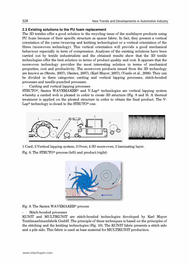
STRUTO®, Santex WAVEMAKER® and V-Lap® technologies are vertical lapping system
whereby a carded web is pleated in order to create 3D structure (Fig. 8 and 9). A thermal
treatment is applied on the pleated structure in order to obtain the final product. The V-
Lap® technology is closed to the STRUTO® one.
1 Card; 2 Vertical lapping system; 3 Oven; 4 3D nonwoven; 5 laminating layer.
Fig. 8. The STRUTO® process (left) and product (right)
Fig. 9. The Santex WAVEMAKER® process
- Stitch-bonded processes
KUNIT and MULTIKUNIT are stitch-bonded technologies developed by Karl Mayer
Textilmaschinenfabrik GmbH. The principle of these techniques is based on the principles of
the stitching and the knitting technologies (Fig. 10). The KUNIT fabric presents a stitch side
and a pile side. This fabric is used as base material for MULTIKUNIT production.
www.intechopen.com

Development of a New 3D Nonwoven for Automotive Trim Applications
329
1 Compound needle; 2 Brush bar; 3 Fibre web; 4 Stitch side; 5 Pile side; 6 KUNIT nonwoven;
7 MULTIKUNIT nonwoven.
Fig. 10. The KUNIT (left) and MULTIKUNIT (right) processes
- Needle-punched process
NAPCO® is a needle-punched technology developed by the textile machinery manufacturer
LAROCHE. The NAPCO® process consists to link two pre-needle nonwovens thanks to a
fibrous bridge (Fig. 11). The obtained 3D structure is mainly used for composite application.
A and B are pre-needle
nonwovens; 1 Stripper plate;
2 Spacer tables; 3 Needles’ area;
4 Fibres’ bridges.
1 Top layer; 2 Bottom layer; 3 Connecting layer
(bridge fibres from 1); 4 Bridge fibres from 2;
5 Needle stitch; 6 Distance between bridge fibres
depending on stitch depth; 7 Distance between
bridge fibres depending on needle density; 8 Take-
out direction; 9 Product thickness depending on
the spacer’s width.
Fig. 11. The NAPCO® process (left) and the obtained 3D structure (right)
www.intechopen.com

New Trends and Developments in Automotive Industry
330
The 3D nonwoven technologies allow producing bulky nonwoven presenting a low density
with a maximal resilience. However, the “on the market” 3D nonwovens obtained through
the existing vertical lapping processes present drawbacks (structure behaviour) that do not
allow them to answer positively to our initial question concerning the replacement of the PU
foam. Indeed, their vertical orientation is not optimum and the structure could be crushed
when vertically compressed with a significant shear moment between top and bottom
surfaces. Consequently, this work aims to answer positively to this question by developing a
new 3D nonwoven obtained through a patented process VERTILAP® of the
N. Schlumberger Company (Dumas et al., 2007). The VERTILAP project aims to develop a
new pleated 3D nonwoven. This project has been conducted in order to involve the different
partners when their skills and know-how were needed in the project. Automotive
upholsteries for headrest and door panels have been also realised in order to demonstrate
the taylorability and formability of the VERTILAP® 3D nonwoven.
3. Presentation of the VERTILAP® process
The VERTILAP® process (Fig. 12) is a vertical lapping system whereby a tow or a web is
pleated thanks to folding elements. The process is composed of four main functions:
- The opening and defibering of the tow
- The verticalisation of the tow
- The extraction and condensation of the pleats
- The thermobonding and the lamination of the 3D pleated structure.
Fig. 12. The VERTILAP® process
The opening of the tow will allow spreading the filaments on the creel. To obtain a good
product’s homogeneity, the tow’s section must be spread as evenly as possible.
The defibering function is a filament separating zone. It is necessary to individualise the
filaments inside the tow. The defibering principle (Fig. 13) consists to separate the filaments
by driving them into a tensioning separating zone. The filament separating cylinder set is
composed of a cylinder with square threading, topped by a rubber coated pressure roller on
which a pneumatic pressure is applied. Along the contacting generator, zones where the
filaments are alternately nipped and released are successive. If we consider two
neighbouring filaments, one will be tightened a little before the other and release a little
www.intechopen.com

Development of a New 3D Nonwoven for Automotive Trim Applications
331
before the other, so that their crimping are not any longer facing each other and will not
reimbricate any more. The tension to carry out in this defibering zone must be lower than
the filament elastic limit. This function of the machine has a considerable influence on the
tow quality. (NSC, 2007)
Fig. 13. The defibering principle
After being defibered, the tow is verticalised in order to create the pleats. These last ones are
then extracted from the verticalisation zone and condensed to obtain the pleated structure.
At this step, additional layers can be joined by thermo binding on the 3D pleated structure
to fix it and to obtain the final multilayer fabric. In this process, the thermal treatment is
essential in the formation and the fixation of the pleats and the 3D structure.
In this study, the VERTILAP® process is presented as an experimental prototype of 20 cm
width. As input, tow was a bi-component co-polyester/ polyester presenting a count of
90 ktex and a filament’s count of 4.4 dtex. The experimental prototype is suitable for tows
presenting a count lower than 30 ktex. A filament separation technique has been developed
to divide the initial tow of 90 ktex into finer ones. The tow has been pleated under the glass
transition temperature of the co-polyester sheet which is 73°C. The obtained 3D nonwovens
present a thickness of 6 mm. The laminating function was done separately thanks to a
flatbed laminating system (Meyer Company, 2007) provided by Protechnic Company
(Fig. 14). The 3D nonwovens have been laminated with external layers made of polyester
and co-polyester hot melt adhesives. The VERTILAP® experimental prototype has been
controlled through the following parameters: tow’s count, speeds before and after the
verticalisation zone, temperature of the verticalisation zone. The laminating process has
been regulated through the speed, the pressure and the temperature.
Fig. 14. The laminating process
www.intechopen.com

New Trends and Developments in Automotive Industry
332
Two kinds of VERTILAP® products have been manufactured: the monolayers and the
multilayers. The obtained multilayer products have always been made of 100% polyester in
order to facilitate their recycling.
4. The experimental study
Experimental study has been made in two campaigns of production, A and B, followed by
complete characterisation test of the manufactured products. For each campaign, the
VERTILAP® products have been compared to automotive PU foams. The tested materials,
the methods and tools of characterisation and the obtained results of the comparative
study between the VERTILAP® products and the PU foams are presented below.
(Njeugna, 2009)
4.1 Tested materials Five different monolayer 3D nonwovens (NT1, NT2, NT3, NT4 and NT5) have been
manufactured in campaigns A and B. From each of them, multilayer products have been
prepared using needle-punched, spun-bonded nonwovens and knitted fabric as external
layers. Two different monolayer foams (m1, m2) classically used by car manufacturers and
representing two kinds of comfort have been tested. The tested automotive multilayer
product (Cm) is composed of three layers, decorative fabric (PET) / PU foam / backing
fabric (PA). The tested samples are presented in Table 1. The description of the different
types of the VERTILAP® multilayer samples is presented in Table 2.
VERTILAP® products
Campaign A Campaign B
PU foams
Monolayer NT1, NT2, NT3,
NT4 NT5 m1, m2
Multilayer L1, L2 L3 Cm
Table 1. The tested samples
NT1, NT2, NT3 and NT4 are 3D nonwoven.
Samples Laminating components
L1 NT40 / 3D nonwoven / NT40 Campaign A
L2 NT44 / 3D nonwoven / NT44
Campaign B L3 NT40 / 3D nonwoven / T200
Table 2. Description of the VERTILAP® multilayer samples
With:
- NT40 is a needle-punched nonwoven presenting a mass per unit area of 40 g/ m².
- NT44 is a spun-bonded nonwoven presenting a mass per unit area of 44 g/ m².
- T200 is a knitted fabric presenting a mass per unit area of 200 g/ m².
www.intechopen.com

Development of a New 3D Nonwoven for Automotive Trim Applications
333
4.2 Methods and tools of characterization 4.2.1 Physical characterization The pleated structure of the 3D nonwoven obtained thanks to VERTILAP® process has been
geometrically described as a triangle after the verticalisation (Fig. 15) and as a loop after the
laminating process (Fig. 16). In both cases, the shape has been characterised by the thickness
(e0), the pleat’s angle (θ), the rate of condensation, the pitch (p) and the fibrous wall
thickness (ep) which has been neglected in order to simplify the model.
The pleat’s angle will indicate the vertical orientation of the pleat. In the case of the
triangular shape, the vertical orientation will be reach with a value of the pleat’s angle
closed to 0°. In the case of the loop shape, the vertical orientation will be reach with a value
of the pleat’s angle closed to 90°.
Fig. 15. Geometrical modelling of the pleat after verticalisation process
After the verticalisation process, the geometrical parameters of the pleat have been defined
by the following equations:
r
p
lp
n= (1)
2 20( ) ( )
2
pa e= + (2)
2. .a pl an= (3)
0
2.arctan( )2.
p
eθ = (4)
100. a rc
a
l lTx
l
−= (5)
Where:
a is the hypotenuse
la is the apparent length of the sample when its pleated structure is flattened
lr is the real length of the sample in its pleated structure
www.intechopen.com

New Trends and Developments in Automotive Industry
334
Fig. 16. Geometrical modelling of the pleat after the laminating process
After the laminating process, the geometrical parameters of the pleat have been defined by
the following equations:
'
2.r
p
lp r
n= = (6)
2 20' ( ) ( )
2
pa e p= − + (7)
. 2. 'loopl p aπ= + (8)
' .a p loopl n l= (9)
0
' arctan2( )
p
e pθ = − (10)
' '
'
'100. a r
c
a
l lT x
l
−= (11)
Where:
a is the hypotenuse
l’a is the apparent length of the sample when its pleated structure is flattened
l’r is the real length of the sample in its pleated structure
lloop is the length of the loop
In the case of the foam, the cellular structure has been geometrically modelled as a pentagon
(Fig. 17) thanks to an adapted method developed from VISIOCELL® used by the OEM
(Original Equipment Manufacturer) (Recticel, 1999), (Drean, 2006). The foam has been
characterised thanks to the horizontal and vertical mean cell sizes. The sizes are measured
on different area of the sample and on a group of five adjacent cells. The characteristics of
the tested foams are presented in Table 3.
The physical characterisation of the 3D nonwoven has been extended to comfort evaluation
which can be evaluated thanks to air permeability (BS 5’636, 1990) and thermal insulation
www.intechopen.com

Development of a New 3D Nonwoven for Automotive Trim Applications
335
Fig. 17. Geometrical modelling of the PU foam
m1 m2 Cm
Thickness (mm) 5 5 4
Weight (g/ m2) 182 180 386
Density (kg/ m3) 36 36 87
Vertical cell mean size, V(µm) 0.25 0.21 0.25
Horizontal cell mean size, H (µm) 0.25 0.31 0.30
Table 3. Characteristics of the tested foams
(Kawabata, 1980). The air permeability measurement has been performed by using the air
permeability tester FX3300 under a pressure of 98 Pa on a surface of 5 cm². The coefficient of
thermal conductivity (K, unit in W/ m.K) has been measured thanks to the KES-FB7
thermolab II of Kawabata Evaluation System for Fabrics. The measurements were
performed at 23°C during 60s on a sample surface of 25 cm². The apparatus have been
customized in order to minimise the air leakage and the heat losses on the lateral edges
(Fig. 18).
Fig. 18. Customization of testing apparatus for air permeability and thermal conductivity
4.2.2 Compression characterization The mechanical characterisation has been focused on the compression behaviour because it
is the most important property to analyse on the new 3D product if compared with the PU
foam. The compression behaviour has been evaluated thanks to two different testing
methods; a first method based on the Kawabata recommendations and a second method
based on automotive standard ISO 3386/ 1: 1986.
www.intechopen.com

New Trends and Developments in Automotive Industry
336
The first testing method has been carried out on the KES-FB3 module. For that, two
procedures have been successively defined, the first one using the standard conditions of
Kawabata and the second one derived from these conditions. In fact, the standard
configuration of the apparatus highlighted during the test an indentation phenomenon on
the pleated material (Fig. 19) which was due to the small surface (2 cm²) of the compression
plate in regards with the testing sample structure (100 cm²): only one or two pleats were
under the pressure foot during the test. (Njeugna et al., 2008)
Fig. 19. Standard configuration of the KES-FB3 compression tester
The second procedure consisted on modifying the surface of the compression plates in order
to compress the testing sample on its whole surface (Fig. 20). The obtained results avoid
indentation phenomenon observed on initial tests. They have also shown the resilient
property of the pleated 3D nonwoven. The second procedure has been validated for the
compression characterisation. The samples have been compressed under a maximal load of
3 kPa at a speed of 12 mm/ min during one cycle. The results give information on the
thickness, the compressibility, the dissipated energy and the resilience of the material.
Fig. 20. Customization of the KES-FB3 compression tester
The second testing method has been carried out on a universal screw driven testing machine
(Instron 33R4204) fitted with 5 kN load cell (Fig. 21). The solicitation speed was at
12 mm/ min. The tests have been performed in static mode. A sanding paper has been fixed
on the surface of the fixed compression plate of the Instron machine in order to eliminate
any slippage of the sample during the test. The samples have been compressed up to 50% of
their initial thickness then decompressed at the same speed until the plates come back to
their initial locations. Five cycles of compression have been performed with a rest time of
10s between each cycle. The stress deformation curves have been plotted. The maximal
stress at 50% deformation of the initial thickness and the dissipated energy have been
determined.
www.intechopen.com

Development of a New 3D Nonwoven for Automotive Trim Applications
337
Fig. 21. INSTRON 33R4204 testing device
4.3 Comparative study: VERTILAP® products vs. PU foams
4.3.1 Campaign A Production of the VERTILAP® products has been made in two steps respectively dedicated
to the preparation of the feeding tow and to the manufacturing of the 3D nonwoven. The
feeding tows have been prepared thanks to a simple manual technique whereby the initial
tow of 90 ktex has been divided into finer tows presenting a count from 9 ktex to 18 ktex.
The obtained tows have been defibered in a converting machine (NSC, 2007) in order to
improve the quality of the filament opening. During the manufacturing process, the speeds
before and after the verticalisation zone have been varied. A digital camera has been used to
observe the products throughout the processing range. These observations have shown
irregularities in the formation of the compacted 3D structure. It has also been observed that
the outgoing product was still hot at the output of the machine. This observation has
allowed showing that the condensation process was not fully controlled. The single 3D
nonwovens have been laminated under a speed of 2 m/ min at 150°C. The hot melt adhesive
was a 25 g/ m² co-polyester web with a melting temperature of 120/ 125°C.
The geometrical modelling of the pleated 3D nonwoven has shown that they present a
pleat’s angle of 41°, a rate of condensation of 65% and a number of pleats/ cm of 2.2. The
pleats in the laminated structure present an angle of 57° and a rate of condensation of 77%.
The pleat’s angle and the rate of condensation have respectively increased of 28% and 16%
after the laminating process.
The results of the physical characterisation have shown that, in the case of monolayer
products (Fig. 22), the 3D nonwovens are thicker and more comfortable in terms of air
permeability than the PU foams. They are less comfortable in terms of thermal insulation
compared to m1 sample. The PU foams are twice lighter than these new products.
In the case of the laminated products (Fig. ), the VERTILAP® products are thicker and more
comfortable in terms of air permeability and thermal insulation than the tested multilayer
foam (Fig. 23). They are also heavier than the tested foam.
The results of the compression behaviour on one cycle test (KES-FB3) have shown that, in
the case of monolayer products (Fig. 24), the 3D nonwovens and the PU foams globally
present the same resilient behaviour. The PU foams are more compressible than the tested
3D nonwovens and they dissipated less energy. This last result shows that the 3D
nonwovens will present better characteristics in term of soft touch compared with the PU
foams.
www.intechopen.com

New Trends and Developments in Automotive Industry
338
0
20
40
60
80Weight (g/m²), Scale1/10
Air permeability (cm3/cm2/s)
K (W/m.K), Scale 1x1000
Thickness (mm), Scale 1x10
m1
m2
NT1
NT2
NT3
NT4
Fig. 22. Physical characteristics of the tested monolayer samples
0,00
20,00
40,00
60,00
80,00Weight (g/m²), Scale1/10
Air permeability (cm3/cm2/s)
K (W/m.K), Scale 1x1000
Thickness (mm), Scale 1x10
Cm
L1_NT1
L1_NT2
L1_NT3
L1_NT4
L2_NT1
L2_NT2
L2_NT3
L2_NT4
Fig. 23. Physical characteristics of the tested multilayer samples
In the case of the laminated products (Fig. 25), the VERTILAP® products laminated with the
needle-punched nonwovens (L1 samples) and the tested foam globally present the same
resilient property while the VERTILAP® products laminated with spun-bonded nonwovens
(L2 samples) are the most resilient. The foam is more compressible than the VERTILAP®
products. The L2 samples and the foam globally present the same characteristic in term of
dissipated energy while the L1 samples dissipate the most energy. It can be said that the L1
samples present the same resilient property than the tested foam but they will be more
comfortable in term of soft touch.
www.intechopen.com

Development of a New 3D Nonwoven for Automotive Trim Applications
339
0,00
20,00
40,00
60,00
80,00
100,00Compressibility (%)
Dissipated energy (N.m/m2)Resilience (%)
m1
m2
NT1
NT2
NT3
NT4
Fig. 24. Compressional characteristics of the tested monolayer samples (KES-FB3)
0,00
20,00
40,00
60,00
80,00
100,00Compressibility (%)
Dissipated energy (N.m/m2)Resilience (%)
Cm
L1_NT1
L1_NT2
L1_NT3
L1_NT4
L2_NT1
L2_NT2
L2_NT3
L2_NT4
Fig. 25. Compressional characteristics of the tested multilayer samples (KES-FB3)
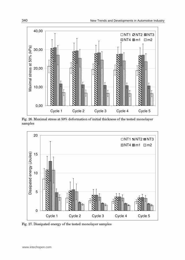
Regarding the compression test on five cycles, it has also been observed that the
VERTILAP® products are more resilient and dissipate more energy than the tested PU
foams. These observations have been done in both cases of the monolayer and laminated
products (Fig. 26 - 29). The analysis of the raw results has shown differences between the
behaviour of the 3D nonwoven and the PU foam. It has been observed an important
reorganisation of the fibrous structure in the case of the 3D nonwoven while the cellular
structure of the PU foam remained more constant. This reorganisation displays different
individual behaviours of the filaments inside the pleated structure.
The results of this campaign have shown interesting properties of the VERTILAP® products
in terms of comfort and mechanical behaviour compared with the tested PU foams. At this
step, the main drawback of this new 3D nonwoven is its weight and its poor reproducibility.
In fact, the obtained results have shown high dispersion values in the case of the
VERTILAP® products. A second campaign has been carried out in order to reach the goal of
the weight reduction of the VERTILAP® products.
www.intechopen.com
New Trends and Developments in Automotive Industry
340
0,00
10,00
20,00
30,00
40,00
Cycle 1 Cycle 2 Cycle 3 Cycle 4 Cycle 5
Maxim
al str
ess a
t 50
% (
kP
a)
NT1 NT2 NT3
NT4 m1 m2
Fig. 26. Maximal stress at 50% deformation of initial thickness of the tested monolayer
samples
0
5
10
15
20
Cycle 1 Cycle 2 Cycle 3 Cycle 4 Cycle 5
Dis
sip
ate
d e
ne
rgy (
Jo
ule
s)
NT1 NT2 NT3
NT4 m1 m2
Fig. 27. Dissipated energy of the tested monolayer samples
www.intechopen.com

Development of a New 3D Nonwoven for Automotive Trim Applications
341
0,00
50,00
100,00
150,00
200,00
Cycle 1 Cycle 2 Cycle 3 Cycle 4 Cycle 5
Max
imal
str
ess
at 5
0%
(kP
a)
L1_NT1 L1_NT2 L1_NT3
L1_NT4 L2_NT1 L2_NT2
L2_NT3 L2_NT4 Cm
Fig. 28. Maximal stress at 50% deformation of initial thickness of the tested multilayer samples
0
20
40
60
80
100
Cycle 1 Cycle 2 Cycle 3 Cycle 4 Cycle 5
Dis
sipat
ed e
ner
gy (
Joule
s)
L1_NT1 L1_NT2 L1_NT3
L1_NT4 L2_NT1 L2_NT2
L2_NT3 L2_NT4 Cm
Fig. 29. Dissipated energy of the tested multilayer samples
www.intechopen.com

New Trends and Developments in Automotive Industry
342
4.3.2 Campaign B In this experiment, the previous production procedure has been applied to manufacture the
VERTILAP® products of this campaign but the technique to divide the initial tow of 90 ktex
has been improved by spreading the tow between two beams in order to apply a minimal
tension necessary for the filaments separation. Tows presenting a count from 7 ktex to
10 ktex have been pleated. During the manufacturing process, the speed before the
verticalisation zone has been varied. The obtained single 3D nonwovens have been
laminated at a speed of 5 m/ min at 120°C. The hot melt adhesive was a 20 g/ m²
co-polyester web with a melting temperature of 60/ 75°C. It is also important to note an
increase of 60% of the laminating speed compared to the previous samples (NT1, NT2, NT3
and NT4). This result enables to validate the products/ process procedure.
The results of characterisation have shown a decrease of the weight of the 3D nonwovens
compared to the previous samples. Indeed, the single 3D nonwovens present a mass per
unit area of 164 g/ m² while the mass per unit area of the laminated ones is 484 g/ m².
Structure’s irregularity has been observed on the manufactured 3D nonwovens. This
irregularity is mainly due to the irregularity in the tow. In fact, finer the tow, the more
irregular the structure is as expressed in the Martindale’s law (Martindale, 1945).
Regarding the physical characteristics (Fig. 30) in the case of the monolayer products, the
objective of lightness has been reached and the 3D nonwoven, NT5, is also more comfortable
in term of air permeability compared with the tested foams (m1, m2). NT5 also presents a
better thermal insulation property compared with m1 sample. In the case of the multilayer
products, the foam (Cm) present better physical characteristics compared with the
laminated 3D nonwoven (L3 sample).
0,00
20,00
40,00
60,00
80,00
100,00Weight (g/m²), Scale1/10
Air permeability (cm3/cm2/s)
K (W/m.K), Scale 1x1000
Thickness (mm), Scale 1x10
m1
m2
NT5
Cm
L3
Fig. 30. Physical characteristics of the tested samples
Regarding the compression properties on one cycle (Fig. 31), a balance has been observed
between the resilience and the dissipated energy in the case of single and laminated 3D
nonwovens. This result shows that this new product presents, simultaneously, good
resilient property and suitable comfort (soft touch). Except the problem of structure’s
irregularity, the characteristics of the obtained 3D nonwovens have been significantly
improved. In both cases of monolayer and multilayer products, it has been observed that the
www.intechopen.com

Development of a New 3D Nonwoven for Automotive Trim Applications
343
VERTILAP® products and the foam present globally the same resilient property but the
foams dissipated less energy. It can be said that, the VERTILAP® products present better
characteristic in term of comfort (soft touch).
0,00
20,00
40,00
60,00
80,00
100,00Compressibility (%)
Dissipated energy (N.m/m2)Resilience (%)
m1
m2
NT5
Cm
L3
Fig. 31. Compressional characteristics of the tested samples
The compression curves of the tested samples are presented on Fig. 32.
0,00
0,50
1,00
1,50
2,00
2,50
3,00
0,00 1,00 2,00 3,00 4,00 5,00 6,00 7,00 8,00
Thickness (mm)
Pre
ssure
(kP
a)
L3
NT5
Cm
m1
m2
Fig. 32. Compression curves on one cycle (KES-FB3) of the tested samples
In addition to the previous characterization, the study of the tailorability of these new
products has been carried out. The tailorability of the VERTILAP® 3D nonwoven has been
positively validated through the execution of upholsteries for a headrest and door panels
(Fig. 33). These automotive prototypes have been visually and tactically assessed thanks to
sensory panelists (Philippe et al., 2004) and textile industrialists.
www.intechopen.com

New Trends and Developments in Automotive Industry
344
Fig. 33. Automotive prototypes with VERTILAP® products
At the end of this campaign, the initial question of PU foam replacement has found a
positive answer. Indeed, the development of the experimental prototype has allowed
improving the quality of the final product especially in terms of weight and comfort in the
case of the monolayer products. Nevertheless, the feeding material presents the problem of
the structure’s irregularity. The final results show that the developed products/ process
procedure has been successfully implemented and has permitted to improve the process
and the expected products.
5. Conclusions and outlook
One original point of the VERTILAP project is the cluster that has been built for it (scientists,
textile companies and competitiveness clusters). This cluster has made possible the
development of an innovative 3D nonwoven. This work has contributed to increase know-
how on the VERTILAP® process and knowledge on the obtained pleated 3D nonwoven in
terms of methods and tools of characterisations. This study has shown that the new 3D
nonwoven present good qualities, in terms of compressional behaviour and comfort (soft
touch, air permeability and thermal insulation), compared to the current automotive PU
foam. The realisation of the automotive parts (headrest and door panel) with this new
product has shown that the VERTILAP® products present good suitable taylorability
properties. At this step of the work, the question initially asked “can the PU foam be
replaced by the VERTILAP® 3D nonwoven?” has found a positive answer and the
recyclability problem has been solved. It can be said that the VERTILAP® 3D nonwoven
could be a good candidate to replace certain PU foam in automotive trim applications.
Moreover, the obtained results during this work have generated data that will be used to
develop a new VERTILAP® prototype of 1m width. This new prototype will be
manufactured by the new subsidiary company NSC Environnement of the NSC Group. This
new machine will allow conducting industrial testing campaign at high speeds of
production. Different feeding materials such as nonwoven web or carded web will be used
in order to obtain a good homogeneity of the product. The obtained 3D nonwovens thanks
to this new prototype will be characterised through more investigations. In fact,
characteristics such as the behaviour modelling, the acoustic insulation, the comfort through
sensory analysis and the taylorability could be realised.
The forthcoming of the VERTILAP project has been initiated in order to extend the
development of the new 3D nonwoven beyond automotive applications. This second phase
has been labelled, in 2009, by the French competitiveness “Fibres Innovative Cluster” . New
www.intechopen.com

Development of a New 3D Nonwoven for Automotive Trim Applications
345
industrial partners (Freudenberg Politex, Paul Hartmann, DIROY, Jacob Holm Industries,
Albany International, Steelcase) have joined the project VERTILAP for this industrial phase.
6. Acknowledgment
This work has been done thanks to the financial support of Alsace Region, the Département
du Haut-Rhin and OSEO.
7. References
Berthier, J-C. (2009), Polyuréthanes PUR, Techniques de l’ingénieur, (janvier 2009), pp 1-20,
AM3425v2
BS 5'636 (1990), Determination of air permeability of textile fabric
Caudron, J.C. (2003), Etude du marché du polyuréthane et Etat de l’art de ses techniques de
recyclage, Rapport de l’ADEME (Agence de l’Environnement et de la Maîtrise de
l’Energie), (27 juin 2003)
DGE (2005), Etude sur les Textiles Techniques, Rapport de la Direction Générale des Entreprises
(DGE), France, (Juin 2005)
Drean, E. (2006), Contribution to the development of piezoelectric sensors for the mechanical
characterisation of textile fabrics, PhD Thesis, University of Haute Alsace, Mulhouse,
France
Dumas, J-L.; Schaffhauser, J-B. (2007). Patent N° WO2007125248, N.Schlumberger Company
EU Directive (2000), Directive 2000/ 53/ CE of the European parliament and council of 18th
September 2000 related to the End Life Vehicle, Official journal of the European
Communities, 2000
Faucon, C. (1995), Les exigences fonctionnelles des matériaux de garnissage dans
l’automobile, Actes du 61ème congrès de l’ACIT, pp 65-80, Lille, juin 1995, France
Fung, W., Hardcastle, M. (2001), Product engineering – Interior trim, Textiles in automotive
engineering, In: Textiles in automotive engineering, The Textile Institute, pp 194-211,
Woodhead Publishing Limited, ISBN 1 85573 493 1, Cambridge, England
Hopkins, J. (1995), A comparative analysis of laminating automotive textiles to foam, Journal
of coated fabrics, (January 1995), pp 250-267
ISO 1798 : 1983, Flexible cellular polymeric materials – Determination of tensile strength and
elongation at break, Ed.2
ISO 3386/ 1: 1986, Polymeric materials, cellular flexible – Determination of stress-strain
characteristics in compression – Part 1: Low density materials
ISO 3795: 1989, Road vehicles, and tractors and machinery for agriculture and forestry –
Determination of burning behaviour of interior materials
ISO 1856: 2000, Flexible cellular polymeric materials – Determination of compression set,
Ed. 3
ITF (1990), Les matériaux textiles utilisés dans les habitacles des véhicules de transport,
Extraits du stage des 23 et 24 octobre 1990, 12, Institut Textile de France, Lyon, France,
(octobre 1990)
Kamprath, A. E. (2004), End-of-Life vehicles Recovery and Recycling polyurethanes Car
Components Options Analysis, Recticel,
http:/ / www.idcpuresearch.com/ downloads.htm
www.intechopen.com

New Trends and Developments in Automotive Industry
346
Karl Mayer Group (2007), Technical textiles, The Karl Mayer guide to Technical Textiles,
http:/ / www.karlmayer.com/ internet/ docs/ MALIMO_EN.pdf, consulted in
January 2007
Kawabata, S. (1980), The standardization and analysis of hand evaluation, (Ed. 2), The
Textile Machinery Society of Japan, Osaka
Martindale, J. G. (1945), A new method of measuring the irregularity of yarns with some
observations on the origin of irregularities in worsted slivers and yarns, Journal of
the Textile Institute, Vol.36, (March 1945), T38-T47
Meyer Company, Flatbed laminating system, Maschinen Fabrik Herbert Meyer GmbH,
www.meyer-machines.com, consulted in November 2007
Némoz, G. (1999), Les textiles (presque) partout dans l’automobile, TUT, N° 32., (2nd quarter
1999) pp16-18
Njeugna, N. (2009), Contribution to the development and the industrialisation of a 3D nonwoven
system, PhD Thesis No. 2009/ 23, University of Haute Alsace, Mulhouse, France
Njeugna, N., Adolphe, D. C., Schacher, L., Schaffhauser, J-B., Strehle, P. (2008), Modification
of compressional testing procedures for 3D nonwoven system for automotive
interior applications, Proceedings of the 4th International Textile Clothing & Design
Conference, pp 859-863, ISBN 978-953-7105-26-6, Dubrovnik, October 2008
NSC (2007), The TT12 crush cutting Converter, Technical notice, http:/ / www.nsc-
fibretoyarn.com, consulted in September 2007
Persijn, B. (2008), PU-foams in automotive, Proceedings of Textile & plastics, 6th International
Conference on Automotive and Transport Interior Decoration, Dec’autex 2008,
Mulhouse, France, november 2008
Philippe, F., Schacher, L., Adolphe, D., and Dacremont, D. (2004), Tactile Feeling: Sensory
Analysis Applied to Textile Goods, Textile Research Journal, 74 (12), 1066-1072
Recticel (2009), What is PU?, Publication of the International Development Centre of Recticel
company,
http:/ / www.idcpuresearch.com/ downloads.htm
Recticel (1999), A new method to measure the cell diameter of polyurethane foam, Visiocell,
Technical Foams, Business Line Management Technical Foams, (Ed. 1), pp 4 - 8,
Damstraat, Belgium
Struto International Inc. (2007), Struto® Nonwoven, http:/ / www.struto.com/ , consulted in
January 2007
Santex Group (2007), Wavemaker® Nonwoven,
http:/ / www.cavitec.ch/ en/ ?menu=produkteprogramm, consulted in January 2007
Vasile, S., Langenhove, L. V., de Meulemeester, S. (2006), Effect of Production Process
Parameters on Different Properties of a Nonwoven Spacer produced on a 3D Web
Linker®, Fibres & Textiles in Eastern Europe, Vol. 14, N°4 (58), (October/ November
2006), pp 68-74
www.intechopen.com

New Trends and Developments in Automotive IndustryEdited by Prof. Marcello Chiaberge
ISBN 978-953-307-999-8Hard cover, 394 pagesPublisher InTechPublished online 08, January, 2011Published in print edition January, 2011
InTech EuropeUniversity Campus STeP Ri Slavka Krautzeka 83/A 51000 Rijeka, Croatia Phone: +385 (51) 770 447 Fax: +385 (51) 686 166www.intechopen.com
InTech ChinaUnit 405, Office Block, Hotel Equatorial Shanghai No.65, Yan An Road (West), Shanghai, 200040, China
Phone: +86-21-62489820 Fax: +86-21-62489821
This book is divided in five main parts (production technology, system production, machinery, design andmaterials) and tries to show emerging solutions in automotive industry fields related to OEMs and no-OEMssectors in order to show the vitality of this leading industry for worldwide economies and related importantimpacts on other industrial sectors and their environmental sub-products.
How to referenceIn order to correctly reference this scholarly work, feel free to copy and paste the following:
Nicole Njeugna, Laurence Schacher, Dominique C. Adolphe, Jean-Baptiste Schaffhauser and Patrick Strehle(2011). Development of a New 3D Nonwoven for Automotive Trim Applications, New Trends andDevelopments in Automotive Industry, Prof. Marcello Chiaberge (Ed.), ISBN: 978-953-307-999-8, InTech,Available from: http://www.intechopen.com/books/new-trends-and-developments-in-automotive-industry/development-of-a-new-3d-nonwoven-for-automotive-trim-applications

© 2011 The Author(s). Licensee IntechOpen. This chapter is distributedunder the terms of the Creative Commons Attribution-NonCommercial-ShareAlike-3.0 License, which permits use, distribution and reproduction fornon-commercial purposes, provided the original is properly cited andderivative works building on this content are distributed under the samelicense.


