Development of A Modular, Cold Gas Propulsion System for ...€¦ · System for Small Satellite...
12
Copyright © A. Deepak Publishing. All rights reserved. www.JoSSonline.com www.DeepakPublishing.com Abstract A novel cold gas propulsion system for small satellites has been developed at the University of Texas at Austin’s Satellite Design Lab. e concept behind the propulsion system is to additively manufacture the main thruster module by means of the stereolithography process. In this manner, intricate features can be created and complex volumes can be used. is method is especially useful for small satellites. e propulsion system operates by releas- ing a saturated liquid propellant serially through three valves and a built-in converging-diverging nozzle. rough extensive tests, the propulsion system was measured with a specific impulse that ranged from 65 seconds at 24ºC to over 89 seconds at 85ºC . e measured thrust force provided by the propulsion system ranged from 110 mN at 24ºC to over 150 mN at 85ºC. A technology demonstration unit has been developed for flight onboard the Uni- versity of Texas at Austin’s Bevo-2 satellite. is system will have a total mass under 400 grams, including 90 grams of Dupont 236-fa as propellant. e propulsion system is expected to provide at least 10 m s -1 of delta-v capability, which has been verified through testing. Development of A Modular, Cold Gas Propulsion System for Small Satellite Applications Steven Arestie, E. Glenn Lightsey, Brian Hudson Department of Aerospace Engineering and Engineering Mechanics, e University of Texas at Austin, TX USA 1. Introduction Recent innovations in small satellite technology, particularly in the miniaturization of electronics, have significantly reduced the cost of access to space. Small satellites allow for a faster and less expensive way to per- form space missions as compared to larger traditional satellites. In particular, the CubeSat platform provides these benefits with its standard bus design. A CubeSat is a small satellite defined in standard units where each unit is ten cubic centimeters. Although CubeSats are individually simpler and less capable than their larger and more expensive counterparts, they have the ad- vantage of being rapidly produced and easily launched into space at lower cost, enabling new mission types that were previously impossible or cost prohibitive. Additionally, this lower cost allows for innovation and development at universities, which provides valuable educational experiences to young engineers and scien- tists. As innovations are incorporated into the state of Corresponding Author: Steven Arestie - [email protected] JoSS, Vol. 1, No. 2, p. 63 Arestie, S., et al. (2012): JoSS, Vol. 1, No. 2, pp. 63-74 (Peer-reviewed article available at www.jossonline.com)
Transcript of Development of A Modular, Cold Gas Propulsion System for ...€¦ · System for Small Satellite...

Copyright © A. Deepak Publishing. All rights reserved.
www.JoSSonline.comwww.DeepakPublishing.com
Abstract
A novel cold gas propulsion system for small satellites has been developed at the University of Texas at Austin’s Satellite Design Lab. The concept behind the propulsion system is to additively manufacture the main thruster module by means of the stereolithography process. In this manner, intricate features can be created and complex volumes can be used. This method is especially useful for small satellites. The propulsion system operates by releas-ing a saturated liquid propellant serially through three valves and a built-in converging-diverging nozzle. Through extensive tests, the propulsion system was measured with a specific impulse that ranged from 65 seconds at 24ºC to over 89 seconds at 85ºC . The measured thrust force provided by the propulsion system ranged from 110 mN at 24ºC to over 150 mN at 85ºC. A technology demonstration unit has been developed for flight onboard the Uni-versity of Texas at Austin’s Bevo-2 satellite. This system will have a total mass under 400 grams, including 90 grams of Dupont 236-fa as propellant. The propulsion system is expected to provide at least 10 m s-1 of delta-v capability, which has been verified through testing.
Development of A Modular, Cold Gas Propulsion System for Small Satellite Applications
Steven Arestie, E. Glenn Lightsey, Brian HudsonDepartment of Aerospace Engineering and Engineering Mechanics, The University of Texas at Austin, TX USA
1. Introduction
Recent innovations in small satellite technology, particularly in the miniaturization of electronics, have significantly reduced the cost of access to space. Small satellites allow for a faster and less expensive way to per-form space missions as compared to larger traditional satellites. In particular, the CubeSat platform provides these benefits with its standard bus design. A CubeSat
is a small satellite defined in standard units where each unit is ten cubic centimeters. Although CubeSats are individually simpler and less capable than their larger and more expensive counterparts, they have the ad-vantage of being rapidly produced and easily launched into space at lower cost, enabling new mission types that were previously impossible or cost prohibitive. Additionally, this lower cost allows for innovation and development at universities, which provides valuable educational experiences to young engineers and scien-tists. As innovations are incorporated into the state of
Corresponding Author: Steven Arestie - [email protected]
JoSS, Vol. 1, No. 2, p. 63
Arestie, S., et al. (2012): JoSS, Vol. 1, No. 2, pp. 63-74(Peer-reviewed article available at www.jossonline.com)

Copyright © A. Deepak Publishing. All rights reserved.
the art, the ability of these satellites to perform more meaningful tasks will be improved.
Small satellite propulsion systems are rare. In gen-eral, capable propulsion systems do not exist for small satellites, especially CubeSats. Those that do exist are often times too complex and expensive for university programs and other lower budget applications. As small satellites become more capable, the mission needs for orbit station keeping, performing translational maneu-vers, and controlled de-orbit burns necessitate equally capable propulsion systems.
1.1 Micro Propulsion System Heritage
Since the term “small satellite” can refer to any sat-ellite less than 500 kg in mass, the description often causes confusion. Propulsion systems designed for sat-ellites on the order of 100-500 kg are fairly mature and generally do not require new innovation and devel-opment. However, there is a need for so-called nano-satellites and picosatellites that are in the mass range of 1-10 kg. For a satellite of this size, traditional pro-pulsive technologies cannot be used, due to the mass, power, and volume constraints of these vehicles. These sub-10 kg satellite propulsion systems are commonly referred to as micro propulsion systems. A few technol-ogy demonstrations have been flown in the past decade with such systems. The most notable missions include the University of Surrey’s first satellite in the Surrey Nanosatellite Applications Program (SNAP-1), the University of Toronto’s Canadian Advanced Nanospace Experiment 2 (CANX-2), and the Aerospace Corpora-tion’s Micro Electro-Mechanical Systems-based Pico-Sat Inspector (MEPSI) satellites. Other micro propul-sion systems are in development. The current research interest in micro propulsion systems is a telling sign of the need for such systems.
The University of Surrey’s SNAP-1 satellite flew a cold-gas propulsion system which had a total mass of 450 g, 32.6 g of which was butane propellant. The system was able to achieve a velocity change of 2.1 m s-1 with an Isp of 48 s (Underwood, 2002). This was achieved by following traditional cold-gas propulsion system design methods with custom tubing, tanks, and valves. Such a design often leads to leaks and assembly
difficulties. The University of Toronto’s CANX-2 satel-lite included a cold gas system that utilized sulfur hexa-fluoride as a propellant (Mauthe, 2005). This system is primarily used as an attitude control thruster. Much like the SNAP-1 system, the CANX-2 propulsion sys-tem was traditional and was therefore not able to uti-lize volume efficiently because of the required room for tooling and piping. The Aerospace Corporation’s MEP-SI satellite flew a small form factor 3D printed thruster module that was to be used with DuPont Suva 236-fa as a propellant. However, the MEPSI satellite flew with 100 psig Xenon gas instead because of a lack of inhib-its as stipulated by NASA for a flight aboard STS-116 (Hinkley, 2008). This latter concept is the foundation of the thruster design presented in this paper.
Other micro electric propulsion systems are cur-rently being developed. These systems are much fur-ther from flight readiness than the design described in this paper. Additionally, electric propulsion systems lack higher levels of impulsive thrust and draw exten-sive amounts of power. Such attributes are important for a CubeSat or other small satellite mission that has a mission lifetime of less than a year and is required to perform significant and timely translational maneu-vers.
1.2 Design Basis
This research focuses on the design of a capable, simple, and inexpensive cold-gas propulsion system that can be applied to many small satellite platforms. Such a thruster system has been designed for a 3U CubeSat platform. However, the design can easily be scaled up or down to accommodate other small satellite applications. The basis of the design is from the origi-nal idea proposed by David Hinkley at the Aerospace Corporation (Hinkley, 2008). The concept is to have the intricacies of a cold-gas propulsion system built into a single module using the rapid prototyping or 3D printing process. Specifically, the thruster is manufac-tured by means of the stereolithography (SLA) process. Effectively, the entire thruster, including the main tank, all secondary tanks, internal piping, and converging-diverging nozzle, is encased in one block of plastic. Such a design has obvious benefits. First, the time it
Arestie, S., et al.
JoSS, Vol. 1, No. 2, p. 64

Copyright © A. Deepak Publishing. All rights reserved.
takes to manufacture the thruster is relatively short. It takes one week or less to go from computer-aided de-sign (CAD) to completed module. Second, the module is inexpensive compared to its traditional counterparts. Third, the design is inherently modular. For example, the nozzle location can be placed practically anywhere, presumably as close to the center of mass of the satel-lite as possible. Lastly, many different propellants can be used without a design change, including non-toxic green propellants.
1.3 3D Printing for Space
Advancements in 3D printing technology have played a significant role in improving the capabilities of prototyping devices. More recently, with the devel-opment of more robust materials and techniques, 3D printing is beginning to be used for functional parts. 3D printed parts, which offer unprecedented custom-ization and detail, have obvious benefits for use in building spacecraft components. As such, it is impor-tant to understand the limitations of the technology for use in space. A specific area of concern is outgassing as a result of porosity within the solidified resins used for 3D printing. Two resins are discussed in this pa-per as possible choices for use with the thruster: the Watershed XC 11122 and the Accura Bluestone ma-terials. Newer resins and printing techniques, such as SLA, offer much better resistance towards outgassing, mass loss, and deformation. For example, the Water-shed 11120 material, the predecessor to XC 11122, has a total mass loss of about three percent in a vacuum (NASA, 2012). The impetus behind new resin develop-ment is to decrease porosity and thus increase a par-ticular material’s strength and resistance to outgassing. The Accura Bluestone material, a ceramic nanocom-posite, offers even better outgassing resistance over the Watershed materials. According to conversations with 3DSystems, Accura Bluestone is almost non-porous. As such, it is very ceramic-like. The Accura Bluestone res-in exhibits practically no outgassing, and has incredibly robust temperature resilience at more than 250 degrees Celsius (3D Systems, 2008 and Miller, 2012). The per-formance offered by current 3D printing technology is more than sufficient for most small satellite missions.
Possible concerns might arise when very precise opti-cal instruments are in use, as particulates tend to con-dense on such instruments.
2. Conceptual 3U-6U CubeSat Design
The development of the cold-gas system outlined in this project is designed specifically to be flown on a 3U CubeSat. As such, the entire thruster system occupies a total volume of less than one half of one CubeSat unit (500 cm3). This includes the main module, propellant, valves, and electronics. Figure 1 illustrates such a sys-tem as it is integrated into the University of Texas at Austin’s Bevo-2 CubeSat, which is scheduled for launch in 2013 (Imken, 2011).
Figure 1. Bevo-2 CubeSat CAD model with thruster in red.
The inherent modularity of such a system offers many benefits. These benefits stem from the volume limitations of 3U and 6U CubeSats. There is usually some best component configuration for any given CubeSat design. The remaining space that exists after the optimal placement of the scientific payloads and other necessary equipment can then be used for the thruster module as seen, for example, in Figure 1. This method was demonstrated firsthand in the develop-ment of the thruster for the Bevo-2 satellite. For Bevo-2, the main requirement on the propulsion system was to provide a total change in velocity, or delta-v, of at least 10 . The Bevo-2 thruster is a technology demonstration experiment which enables the CubeSat to perform proximity operations with another satellite.
Development of A Modular, Cold Gas Propulsion System for Small Satellite Applications
JoSS, Vol. 1, No. 2, p. 65

Copyright © A. Deepak Publishing. All rights reserved.
3. Thruster Design
As previously described, this cold-gas thruster is entirely rapid prototyped. Specifically, the thruster modules are built using the stereolithography print-ing process. The advancement of 3D printing technol-ogy has been astounding, and the fidelity that can be achieved through this process is continually improving. Presently, by the stereolithography process, parts can be printed in layers with a thickness of as little as 0.1 mm (InterPro, 2012). With such capability, extremely precise features can be built into the design such as a converging-diverging thruster nozzle. A thruster mod-ule that is fabricated in this manner has the benefit of having very few locations for possible leakage, as most of the hardware intricacies are contained in one piece. The significance of such a design, especially for a small satellite, is that there is no need to waste vol-ume for tooling to bend pipes or tighten nuts, which is incurred by traditional propulsion systems. Effectively, the thruster can be assembled, filled with propellant, sealed, and integrated into the satellite. The result of this approach is an offering of simplicity, robustness, and cost savings over traditional cold-gas and electric propulsion systems.
3.1 Concept of Operations
The mechanism by which this system produces thrust is quite simple. The thruster is entirely pressure driven. The propellant is fed serially from the main tank through three valves and two plenums, or smaller tanks, as shown in Figure 2. The propellant is stored mostly as a saturated liquid in the main tank. Some of the propellant is then released into the first plenum when the first valve actuates. The propellant exists as a liquid and gas mixture in this first plenum. Then, the propellant is driven by a pressure differential into the second plenum once the second valve has been actu-ated. The second plenum is sized in such a way so as to ensure that all of the propellant resides in vapor form. That is, if the propellant is entirely liquid in the first plenum, there is enough volume in the second plenum for all of this propellant to expand to a vapor. This va-por propellant is then released with the third valve ac-
tuation into the vacuum of space through an embed-ded converging-diverging nozzle.
Figure 2. Thruster module design schematic.
For the current thruster design, there are no active sensor measurements, such as pressure transducers. Instead, the thruster will be operated passively with two inputs: the desired total change in velocity and the ambient temperature. The results that are presented in this paper provide for a mapping of the expected per-formance from a given temperature. Each valve will be opened for about one second before it is closed, at which time the subsequent valve is opened. There will be a delay time between the first and second plenum, so that the propellant can regain some energy lost due to cooling from expansion. This operating procedure should provide for repeatable results for most of the propellant life, until little propellant is left in the main tank.
With this design, the thruster produces momen-tum exchange thrust force by means of variable pulse widths. The expected thrust force and change in veloc-ity per pulse has been measured from ground testing. Extensive tests were performed on the current design, which are presented in this report. Additionally, accel-erometers will measure the thrust force on orbit. In this way, auxiliary sensing by means of a guidance and con-trol system will more accurately determine the on-orbit performance characteristics of the thruster.
The robustness of the thruster design extends to the selection of the propellant. The thruster can be oper-ated using many different saturated liquids and pres-surized gases and designed to function in accordance
Arestie, S., et al.
JoSS, Vol. 1, No. 2, p. 66

Copyright © A. Deepak Publishing. All rights reserved.
with the operating pressures of the chosen propellant. Of course, higher vapor pressures will result in greater performance, but higher pressures will also require a stronger material and perhaps a stronger design. For the thruster system designed for the Bevo-2 satellite, Dupont Suva 236-fa refrigerant was used. Suva 236-fa was chosen as the propellant because it offers the maximum allowable vapor pressure at 56ºC before the system would be considered a pressure vessel under NASA regulations. NASA specifications dictate that a pressure vessel is any sealed contained at a pressure greater than 100 psi (NSTS 1700.7B, 2003). In order to fly with a pressure vessel, a waiver is often needed and a launch as a secondary payload is much harder to ob-tain. Suva 236-fa has a vapor pressure of 100 psi at 56ºC (Dupont, 2005). Therefore, by showing that the Bevo-2 satellite temperature will be below 56ºC at all times during launch, the thruster is classified as a container and not as a pressure vessel, which has easier certifica-tion standards.
3.2 Design Description
The physical layout of the Bevo-2 thruster has changed extensively from preliminary to detailed de-sign. This demonstrates the inherent modularity of the approach. In less than two years, five different thruster modules have been designed, fabricated, and tested. Each successive design has built upon the lessons learned from previous modules. Figure 3 depicts the CAD models of two such modules. The inner workings of the thruster are clearly visible in the third iteration in this Figure.
Figure 3. Third iteration module (left) and fifth iteration module (right).
The biggest design change between the modules represented in Figure 3 is the valves. Extensive valve trade studies have been performed with the addition of exhaustive functionality tests. In doing so, the Lee Company Extended performance valves were selected for this application and have been tested on the fourth and fifth iteration modules (The Lee Company, 2010). These valves demonstrated temperature, pressure, and propellant compatibility robustness during testing. Figure 4 shows the fully integrated fourth iteration module. Thrust determination tests were conducted on this module in a vacuum chamber and the results of these tests are presented in this report.
Figure 4. Fourth iteration fully integrated module.
The on-orbit technology demonstration experi-ment for this thruster is planned to occur on the Bevo-2 satellite in 2013. The Bevo-2 satellite design has un-dergone many design changes over its life cycle. For a more traditional propulsion system, accommodating these spacecraft design changes would be a labor-inten-sive, costly, and risky process. For the thruster concept that was implemented for Bevo-2, it was relatively easy to modify the thruster to accommodate the spacecraft design changes. For example, the first four thruster modules were designed to be located at the end of the Bevo-2 satellite. After a component placement design trade was performed, the decision was made to move the entire attitude determination and control system, including the thruster, closer to the spacecraft center of mass near the middle of the satellite, as shown in Figure 1. Within three weeks, a fifth iteration module was designed and manufactured with the same operat-ing principles as the first four modules. The ability for quick design progression is critical for a satellite with such a small form factor, especially for low budget,
Development of A Modular, Cold Gas Propulsion System for Small Satellite Applications
JoSS, Vol. 1, No. 2, p. 67

Copyright © A. Deepak Publishing. All rights reserved.
rapidly developed university satellites. Figure 5 shows a picture of the fabricated fifth iteration module and a close up view of the built-in converging-diverging nozzle.
Figure 5. Fifth iteration Watershed XC11122 fabricated thruster module (left) with converging-diverging nozzle highlight (right).
All of these modules were designed using the same SLA process, but with different fabricated materials. The Watershed XC11122 resin was the first material of choice, as it was used by the Aerospace Corporation in their 3D printed thruster which flew on MEPSI and offered the benefit of being clear (Hinkley, 2008) and (DSMProduct, 2009). This material is shown in Figure 5 with the fifth iteration module. After a design trade, the decision was made to change to the Accura Bluestone resin. This resin offers a much higher material strength and better temperature tolerance than the Watershed XC11122 material (DSMProduct, 2009) and (3DSystems, 2008). This material is shown in Figure 4 with the fourth iteration module and in Figure 6 with the flight-ready fifth iteration module. Both materials are relatively low cost, with an entire module costing less than $1000, which makes fabricating and testing additional units to characterize the design performance cost effective. The fifth iteration flight thruster module system description is shown in Figure 6 and the design properties are listed in Table 1.
For small satellites in particular, much importance is placed on power usage. There is only so much power that can be extracted from the solar cells and batteries with such a small form factor. As a result, components must be switched on and off to prevent excessive power draw. The characterization of the power draw by the Lee Co valves was critical in ensuring a favorable overall satellite power configuration. One benefit of the
Lee Co valves is that the power needed for activation is a strong function of the operating pressure.
Considering the Lee Valves are rated to 800 psig and the operating pressures of the thruster are at most 100 psig, the greatest power needed for activation was determined to be approximately 1.5 W as opposed to several Watts. The power required to hold the valves open is approximately 0.5 W. For this reason, when valves are actuated at a high rate, the total power draw can be assumed to be 1.5 W, as only one valve is actuated at a time. The Bevo-2 satellite, for example, can provide between 5 and 8 W at a given time. Obviously, certain components must be turned off during a propulsive maneuver, but overall, there should be enough power to operate the thruster, ADC system, and other critical systems simultaneously.
Figure 6. Fifth iteration Accura Bluestone fabricated thruster module.
Table 1. Bevo-2 thruster system specifications.
Thruster System Characteristic ValueTotal dry mass 290 gramsPropellant mass 90 gramsTotal thruster system mass 380 gramsMinimum power 0 WMaximum power 1.5 WMaximum valve operation pressure 800 psigValve actuation rate 500 HzDimensions 10 x 9 x 4.4 cm
Arestie, S., et al.
JoSS, Vol. 1, No. 2, p. 68
Copyright © A. Deepak Publishing. All rights reserved.
4. Test Results and Performance
The ability to quantitatively test low thrust systems in the Satellite Design Lab at the University of Texas at Austin did not exist before the design and development of this cold gas propulsion system. The need to experi-mentally measure the performance parameters of the thruster became evident quickly, and a custom thrust determination mechanism was developed for this pur-pose. The goal of the mechanism was not to determine high fidelity performance parameters; instead, the ap-paratus was used to obtain lower fidelity performance characteristics and to provide a way to observe the re-peatability of the thruster during operation.
4.1 Testing Apparatus and Procedure Overview
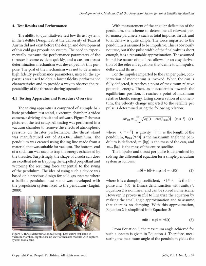
The testing apparatus is comprised of a simple bal-listic pendulum test stand, a vacuum chamber, a video camera, a driving circuit and software. Figure 7 shows a picture of the test setup. All testing was performed in a vacuum chamber to remove the effects of atmospheric pressure on thruster performance. The thrust stand was manufactured out of AL-6061 aluminum. The pendulum was created using fishing line made from a material that was suitable for vacuum. The bottom-end of a soda can was used to trap the energy exhausted by the thruster. Surprisingly, the shape of a soda can does an excellent job in trapping the expelled propellant and vectoring the resulting force tangential to the swing of the pendulum. The idea of using such a device was based on a previous design for cold gas systems where a ballistic-pendulum test stand was developed with the propulsion system fixed to the pendulum (Lugini, 2009).
Figure 7. Thrust determination test setup. Left: entire test stand in vacuum chamber, Right: close up view of thruster module with capture system (soda can).
With measurement of the angular deflection of the pendulum, the scheme to determine all relevant per-formance parameters such as total impulse, thrust, and total delta-v is quite simple. The force imparted to the pendulum is assumed to be impulsive. This is obviously not true, but if the pulse width of the final valve is short enough, it is a reasonable approximation. The assumed impulsive nature of the force allows for an easy deriva-tion of the relevant equations that define total impulse, delta-v, and thrust.
For the impulse imparted to the can per pulse, con-servation of momentum is invoked. When the can is fully deflected, it reaches a point of maximum relative potential energy. Then, as it accelerates towards the equilibrium position, it reaches a point of maximum relative kinetic energy. Using conservation of momen-tum, the velocity change imparted to the satellite per pulse is determined using the following relation:
where is gravity, is the length of the pendulum, is the maximum angle the pen-dulum is deflected, m [kg] is the mass of the can, and is the mass of the entire satellite.
The impulse and thrust per pulse is determined by solving the differential equation for a simple pendulum system as follows:
where b is a damping coefficient, is the im-pulse and is Dirac’s delta function with units s-1. Equation 2 is nonlinear and can be solved numerically. However, it proves useful to linearize the equation by making the small angle approximation and to assume that there is no damping. With this approximation, Equation 2 is simplified into Equation 3:
From Equation 3, the maximum angle achieved for such a system is given in Equation 4. Therefore, mea-suring the maximum angle of the pendulum yields the
∆v��� � mm���
�2gl�� � ��s����� �m s��� ���
g �m s��� l �m�
�� ����s� m��� ��g�
mlθ� � �lθ� � mgs��θ � τδ�t� �2� τ �� � s� δ�t�
mlθ� � mgθ � τδ�t� ���
θ��� � τ m�gl ����s� ���
τ � θ���m�gl �� � s� �5�
� � ∆v���m���∆t����� ��� ���
∆v��� ∆t�����
��t�l ∆v � ����������������� ��� I�� � ����������������� ���
I�� � ∆vgl��m�m�
� ���
m�m�
5 μm s��
Development of A Modular, Cold Gas Propulsion System for Small Satellite Applications
JoSS, Vol. 1, No. 2, p. 69

Copyright © A. Deepak Publishing. All rights reserved.
impulse of a thruster pulse, as shown in Equation 5.
Finally, the thrust force per pulse is calculated by integrating Newton’s second law and by assuming that the thrust force is constant in time for the duration of the short pulse. The thrust per pulse is given by Equa-tion 6:
where is the total change in velocity of the satellite per pulse (given in Equation 1), and [s] is the time that the last valve is open.
As with any momentum trap design, there are cer-tain limitations in the accuracy of measurements. The losses that exist are quite difficult to determine, and can best be observed by comparing the results with a per-fect isentropic expansion analysis, as is to come in a later section. The difference between the ideal case and what is observed can be attributed to the coupled ef-fect of both thruster performance and momentum test stand errors. However, for the purposes of character-izing the thruster as presented in this paper, this setup provided sufficient capabilities. Specifically, such a test stand design allows for the observation of repeatability for a certain thrusting scheme and a conservative esti-mate for thruster performance.
A driving circuit interfaced with National Instru-ments LabView software controlled the actuation of all three valves. The purpose of the driving circuit was to provide a voltage source that could be actuated by a digital signal supplied by a computer. Custom LabView software was developed that allowed for precise timing of each valve command, timing between valve actua-tions, and timing between successive pulse cycles. The code is robust, in that it allows for variable valve cy-cling schemes which are used to optimize the thruster module for various operational conditions and thrust requirements.
The procedure used to determine the relevant per-formance parameters begins with an accurate mea-surement of the mass per pulse expelled by the thruster for a fixed valve cycling scheme. The mass of the entire module, including propellant mass, was recorded be-fore the thruster was placed into the vacuum chamber. The thruster was then pulsed dozens of times at a high vacuum (5E-5 torr pressure). The entire module mass was then measured after operation, and the average mass expelled per pulse could readily be determined. With the mass expelled per pulse information for a giv-en valve cycling scheme, the performance parameters were determined with the ballistic pendulum test stand testing method as described above.
4.2 Thruster Performance Results
Thrust and delta-v determination tests have been ongoing in the Satellite Design Lab since November 2011, and will continue in the future. The testing meth-ods have been refined to produce better results. Primar-ily, the switch to faster actuating valves (500 Hz) during the design process, as was described earlier, allowed for a pulse profile that was more indicative of a true impul-sive force. It became clear that with the slower valves (100 Hz), some of the propellant that is expelled does not fully impart its mass onto the pendulum. When the pendulum deflects, and the last valve is still open, some of the energy of the velocity of the propellant is not transferred to the kinetic energy of the can. After this valve switch was made, the resulting calculations revealed much better thruster performance which was expected.
With the test setup already described, the delta-v per pulse was determined by measuring the maximum angle for several pulses coupled with Equation 1. Ad-ditionally, the total delta-v can be determined for a defined total propellant mass with knowledge of the delta-v per pulse, mass expelled per pulse and total satellite mass. The mass of the satellite changes as the propellant is expelled, so the thrust force per pulse is not quite linear as the propellant is depleted. However, with an expected propellant mass of 90 g, and a total satellite mass of 4 kg (standard 3U CubeSat mass), the change of mass can be neglected. The results for one
∆v��� � mm���
�2gl�� � ��s����� �m s��� ���
g �m s��� l �m�
�� ����s� m��� ��g�
mlθ� � �lθ� � mgs��θ � τδ�t� �2� τ �� � s� δ�t�
mlθ� � mgθ � τδ�t� ���
θ��� � τ m�gl ����s� ���
τ � θ���m�gl �� � s� �5�
� � ∆v���m���∆t����� ��� ���
∆v��� ∆t�����
��t�l ∆v � ����������������� ��� I�� � ����������������� ���
I�� � ∆vgl��m�m�
� ���
m�m�
5 μm s��
Arestie, S., et al.
JoSS, Vol. 1, No. 2, p. 70

Copyright © A. Deepak Publishing. All rights reserved.
such data set at room temperature (24ºC) are given in Figure 8. From Figure 8, the repeatability of the delta-v per pulse is quite good, with a standard deviation of about . With these results, using the current thruster design for the Bevo-2 satellite, the total delta-v capacity of the system is expected to be over 14.5 m s-1. The total delta-v was determined by multiplying the total number of pulses for 90 g of propellant by the average delta-v per pulse obtained from Figure 8. The uncertainty in the total delta-v value that arises from measurement error is at most 0.5 m s-1. The Bevo-2 mission design requirement is 10 m s-1, so this design meets the mission requirement. This testing scheme is inherently conservative, in that the results predicted by the test should be less than what can be expected in space. This is due to the fact that an impulsive thrust assumption was made, the tests were performed at a less than space vacuum (5E-5 torr pressure), and the mass change per pulse was not included in the analysis. Dupont Suva 236-fa is the propellant used for all of the results presented.
Figure 8. Delta-v per pulse and total delta-v for 4 kg satellite.
The testing procedure previously described was re-peated for many different operational modes. In par-ticular, the testing procedure was performed for three different ambient temperatures: 24ºC, 44ºC, and 85ºC. The measured results allowed delta-v and specific im-pulse thruster performance to be related to ambient
temperature. Plots of the measured total delta-v and specific impulse as a function of temperature are shown in Figures 9 and 10. An exponential curve fit was per-formed on both the measured total delta-v and specific impulse to obtain a continuous relation, and is defined by Equations 7 and 8 as follows:
The total delta-v was determined empirically with lab results, while the specific impulse was derived ana-lytically with the ideal rocket equation in Equation 9:
where is the propellant mass ratio, and is simple to determine with a known total propellant mass of 90 g.
Figure 9. Delta-v versus temperature.
Figure 10. Specific impulse versus temperature.
∆v��� � mm���
�2gl�� � ��s����� �m s��� ���
g �m s��� l �m�
�� ����s� m��� ��g�
mlθ� � �lθ� � mgs��θ � τδ�t� �2� τ �� � s� δ�t�
mlθ� � mgθ � τδ�t� ���
θ��� � τ m�gl ����s� ���
τ � θ���m�gl �� � s� �5�
� � ∆v���m���∆t����� ��� ���
∆v��� ∆t�����
��t�l ∆v � ����������������� ��� I�� � ����������������� ���
I�� � ∆vgl��m�m�
� ���
m�m�
5 μm s��
1 2 3 4 5 6 7 8 9 100
0.5
1
1.5
2
2.5
3
3.5
4
4.5
5x 10
-4
Pulse
Del
ta-v
per
pul
se [m
s-1
]
10 Pulses at 24deg C, σ = 5.0904e-006 m s-1
14.5749 [m s-1] Numerically
14.6494 [m s-1] Energy Methods
0 10 20 30 40 50 60 70 80 90 1005
10
15
20
25
30
Temperature [oC]
Total
delta
−v [m
s−1]
90 g of Dupont Suva−236fa propellant for 4 kg satellite
Data PointsExponential Fit
0 10 20 30 40 50 60 70 80 90 10040
50
60
70
80
90
100
110
120
Temperature [oC]
I sp [s]
Dupont Suva−236fa propellant
Data PointsExponential Fit
Development of A Modular, Cold Gas Propulsion System for Small Satellite Applications
JoSS, Vol. 1, No. 2, p. 71
Copyright © A. Deepak Publishing. All rights reserved.
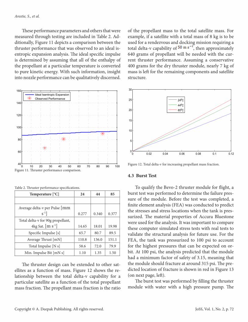
These performance parameters and others that were measured through testing are included in Table 2. Ad-ditionally, Figure 11 depicts a comparison between the thruster performance that was observed to an ideal is-entropic expansion analysis. The ideal specific impulse is determined by assuming that all of the enthalpy of the propellant at a particular temperature is converted to pure kinetic energy. With such information, insight into nozzle performance can be qualitatively discerned.
Figure 11. Thruster performance comparison.
Table 2. Thruster performance specifications.
Temperature [°C] 24 44 85
Average delta-v per Pulse [mm s-1] 0.277 0.340 0.377
Total delta-v for 90g propellant, 4kg Sat. [m s-1] 14.65 18.01 19.98
Specific Impulse [s] 65.7 80.7 89.5Average Thrust [mN] 110.8 136.0 151.1Total Impulse [N s] 58.6 72.0 79.9
Min. Impulse Bit [mN s] 1.10 1.35 1.50
The thruster design can be extended to other sat-ellites as a function of mass. Figure 12 shows the re-lationship between the total delta-v capability for a particular satellite as a function of the total propellant mass fraction. The propellant mass fraction is the ratio
of the propellant mass to the total satellite mass. For example, if a satellite with a total mass of 8 kg is to be used for a rendezvous and docking mission requiring a total delta-v capability of , then approximately 640 grams of propellant will be needed with the cur-rent thruster performance. Assuming a conservative 400 grams for the dry thruster module, nearly 7 kg of mass is left for the remaining components and satellite structure.
Figure 12. Total delta-v for increasing propellant mass fraction.
4.3 Burst Test
To qualify the Bevo-2 thruster module for flight, a burst test was performed to determine the failure pres-sure of the module. Before the test was completed, a finite element analysis (FEA) was conducted to predict the stresses and stress locations when the tank is pres-surized. The material properties of Accura Bluestone were used for the analysis. It was important to compare these computer simulated stress tests with real tests to validate the structural analysis for future use. For the FEA, the tank was pressurized to 100 psi to account for the highest pressures that can be expected on or-bit. At 100 psi, the analysis predicted that the module had a minimum factor of safety of 3.15, meaning that the module should fracture at around 315 psi. The pre-dicted location of fracture is shown in red in Figure 13 (on next page, left).
The burst test was performed by filling the thruster module with water with a high pressure pump. The
0 10 20 30 40 50 60 70 80 90 10040
60
80
100
120
140
160
Temperature [oC]
I sp [s
]
Dupont Suva−236fa propellant
Ideal Isentropic ExpansionObserved Performance
0 0.02 0.04 0.06 0.08 0.1 0.120
5
10
15
20
25
30
Propellant Mass Fraction
Tota
l del
ta−v
[m s
−1]
24oC
44oC85oC
Arestie, S., et al.
JoSS, Vol. 1, No. 2, p. 72

Copyright © A. Deepak Publishing. All rights reserved.
pressure was slowly increased until failure. The maxi-mum pressure reached before failure was 329 psi. Con-sidering the test was performed at one atmosphere of pressure, the maximum pressure attained was about 314 psig. This value matched remarkably well with the FEA prediction. Additionally, the location of fracture was predicted correctly with the FEA simulation as is shown in Figure 13. From this Figure, it is clear that the fracture initiated from main tank exterior corners.
Figure 13. Finite element analysis (left) and burst test result (right).
5. Further Research
In the near future, better delta-v and thrust force models will be developed by means of a higher fidelity force sensor. In doing so, knowledge about the thrust profile can be determined and used in the analysis. Ad-ditionally, if future applications require better perfor-mance, a warm-gas propulsion system can be investi-gated. Such a system will be almost identical, with the addition of a low power resistive heater that serves to increase the temperature and thus pressure of the pro-pellant. Further in the future, 3D printing should prove very useful in the development of more advanced small satellite propulsion systems, including hybrid and monopropellant systems.
6. Conclusion
Small satellites will play an increasing role in space. Consequently, an increase in the capabilities of small satellites will require equally capable propulsion sys-tems. The technology for simple and reliable propul-sion options for smaller satellites, especially CubeSats, is limited. The development of the novel propulsion system presented in this paper provides a new option
for filling the need that currently exists for this class of small satellites. The thruster allows for a high degree of customization and modularity in design and fabri-cation. Additionally, the concept of printing the entire thruster module is quite beneficial for rapid and lower budget satellite development. The testing and analysis presented in this paper shows that the thruster concept, which is simple and robust, is very capable and behaves in a predictable manner that may be incorporated into future small satellite missions.
Acknowledgments
The authors would like to acknowledge and thank all of the graduate and undergraduate students in-volved in the University of Texas at Austin’s Satellite Design Lab. They would also like to thank their col-leagues from the Air Force Research Laboratories and NASA Johnson Space Center who have made this work possible by providing expertise and support through-out the entire project. Lastly, the authors would like to express their appreciation to the engineers at the Aero-space Corporation for their work on small satellite propulsion systems which has heavily influenced this thruster development.
References
DSMProduct. (2009): WaterShed XC 11122 Data Sheet. Dupont. (2005): Thermodynamic Properties of HFC-
236fa (1,1,1,3,3,3-hexafluoropropane). Hinkley, D. (2008): A Novel Cold Gas Propulsion Sys-
tem for Nanosatellites and Picosatellites, in Proc. 22nd Annu. AIAA/USU Conf. Small Satellites, Lo-gan, UT.
Imken, T. (2011): Design and development of a modu-lar CubeSat bus, Engineering Honors Undergradu-ate Thesis, Dept. Aerospace Eng. and Eng. Mech., Univ. Texas, Austin.
InterPro website. http://www.interpromodels.com/ser-vices/SLAstereo.html, (accessed May 2012).
Lugini, C. and M. Romano. (2009): A ballistic-pendu-lum test stand to characterize small cold-gas thrust-
Development of A Modular, Cold Gas Propulsion System for Small Satellite Applications
JoSS, Vol. 1, No. 2, p. 73

Copyright © A. Deepak Publishing. All rights reserved.
er nozzles. Acta Astronautica, vol. 64, pp. 615-625. Netherlands: Elsevier.
Mauthe, S., et al. (2005): The design and test of a com-pact propulsion system for CanX nanosatellite for-mation flying, in Proc. 19th Annu. AIAA/USU Conf. Small Satellites, Logan, UT.
Miller, P. (2012) 3DSystems Telephone Conversation. July 26, 2012. NASA Outgassing website. outgas-sing.nasa.gov. (accessed July 2012).
NSTS 1700.7B, App. A 2003.The Lee Company. (2010): Extended Performance So-
lenoid Valve Product Data Sheet. Underwood, C., et al. (2003): In-orbit results from
SNAP-1 nanosatellite and its future potential. Phil. Trans. R. Soc. Lond., vol 361, pp. 199-203. London.
3DSystems. (2008): Accura Bluestone Plastic Data Sheet.
Arestie, S., et al.
JoSS, Vol. 1, No. 2, p. 74