Development of a Magnetic Levitation System for Additive ...
8
0018-9464 (c) 2020 IEEE. Personal use is permitted, but republication/redistribution requires IEEE permission. See http://www.ieee.org/publications_standards/publications/rights/index.html for more information. This article has been accepted for publication in a future issue of this journal, but has not been fully edited. Content may change prior to final publication. Citation information: DOI 10.1109/TMAG.2020.2997759, IEEE Transactions on Magnetics 1 Development of a Magnetic Levitation System for Additive Manufacturing: Simulation Analyses Parichit Kumar, Yuze Huang, Ehsan Toyserkani, Mir Behrad Khamesee Member, IEEE,, Department of Mechanical and Mechatronics Engineering, University of Waterloo, Waterloo, Ontario, Canada, N2L 3G1 Abstract—Magnetic levitation has been always a very promis- ing field. Due to its versatility, it has garnered interest in fields energy harvesting, high speed transportation and high precision micro-manipulation amongst other fields. However, it’s application within the sphere of Additive Manufacturing (AM) has been negligible. Thus, for the first time, the work conducted here works with the development of a novel technique utilizing magnetic levitation for stable suspension for AM. Current AM technique are heavily dependent on the building the part on a substrate. The substrate limits the use of multiple material nozzles and also requires significant post-processing. The use of the principle of magnetic levitation can bypass the need for this substrate. Primary emphasis is placed on computation of eddy currents and Lorentz force produced from the magnetic levitation system and also on finding the relevant parameters affecting several output parameters like position of levitation, force experienced by the object suspended etc. A temperature analysis is also conducted to ensure that the principles used here are valid. ANSYS Ansoft Maxwell Modules are used to determine these input parameters. The work is subsequently validated through the transient module of the same module. The results presented here depict the viability of the system within the AM environment and the successful elimination of the need for a substrate. Index Terms—Magnetic Levitation, Stable Suspension, Eddy Currents, Additive Manufacturing I. I NTRODUCTION A DDITIVE manufacturing (AM) is the process of manu- facturing objects from 3-Dimensional data. AM employs layer by layer addition of material to build the part [1]. There are several types of AM. The work conducted here primarily focuses on the Direct Energy Deposition (DED) technique. Also known as Direct Metal Deposition (DMD) technique, DED is an AM technique that utilizes the concept of simul- taneously feeding powder with an energy source (eg. laser) to build the part. This technique also incorporates the principle of layer by layer addition for its successful implementation [2]. DED techniques have several advantages within the AM environment. For instance, DED has a high material deposition rate and high material utilization. In addition, this technique is superior for repair and add-on based applications. This technique can also be used for the installation of wear-resistant materials on products for extending life [3]. The authors are with the Department of Mechanical and Mechatronics Engineering, University of Waterloo, Waterloo, Ontario, Canada, N2L 3G1. Corresponding Author: M.B. Khamesee, [email protected] Fig. 1: Conventional Direct Metal Deposition Technique from [4] As it can be seen in Fig. 1, there is a very strong dependence on the use of a substrate for its successful implementation. The primary function of the substrate is to constrain the article being manufacturing. The part being manufacturing is fused to the substrate to ensure that there is no motion in the x-y plane. The part is subsequently built layer by layer in the z axis [5]. [5] also studies the build up of residual stresses during the manufacturing process. Due to the constraining feature of the substrate, these stresses cannot be relieved. Thus, the articles being built are vulnerable to fracture. The work shown in this paper aims to bypass the need for this substrate. This is done through the use of magnetic levitation principles to actively levitate the article being manufacturing and producing the necessary restoration forces to stably hold the object. Fig. 1 depicts a conventional system setup for this technique. It can be seen that the system is constrained to the use of a single nozzle for material deposition. However, by the incor- poration of Magnetic Levitation principles, multiple nozzles can be employed to enable faster manufacturing capabilities. Use of eddy currents to generate forces has been a popular means of generating non-contact forces. [6] studies the use of eddy currents to generate stabilizing restoration forces on tumbling uncontrolled satellites, thereby showing the viability of the principle. The primary principle of operation is the principle of Electro-dynamic Suspension (EDS) to facilitate stable sus- pension. EDS has garnered a lot of attention in applications like high speed MagLev Trains. [7] develops a theoretical model and also conducts an experimental study of two magnets Authorized licensed use limited to: University College London. Downloaded on June 11,2020 at 08:09:31 UTC from IEEE Xplore. Restrictions apply.
Transcript of Development of a Magnetic Levitation System for Additive ...

0018-9464 (c) 2020 IEEE. Personal use is permitted, but republication/redistribution requires IEEE permission. See http://www.ieee.org/publications_standards/publications/rights/index.html for more information.
This article has been accepted for publication in a future issue of this journal, but has not been fully edited. Content may change prior to final publication. Citation information: DOI 10.1109/TMAG.2020.2997759, IEEETransactions on Magnetics
1
Development of a Magnetic Levitation System forAdditive Manufacturing: Simulation Analyses
Parichit Kumar, Yuze Huang, Ehsan Toyserkani, Mir Behrad Khamesee Member, IEEE,,
Department of Mechanical and Mechatronics Engineering, University of Waterloo, Waterloo, Ontario, Canada,N2L 3G1
Abstract—Magnetic levitation has been always a very promis-ing field. Due to its versatility, it has garnered interest infields energy harvesting, high speed transportation and highprecision micro-manipulation amongst other fields. However, it’sapplication within the sphere of Additive Manufacturing (AM)has been negligible. Thus, for the first time, the work conductedhere works with the development of a novel technique utilizingmagnetic levitation for stable suspension for AM. Current AMtechnique are heavily dependent on the building the part ona substrate. The substrate limits the use of multiple materialnozzles and also requires significant post-processing. The useof the principle of magnetic levitation can bypass the need forthis substrate. Primary emphasis is placed on computation ofeddy currents and Lorentz force produced from the magneticlevitation system and also on finding the relevant parametersaffecting several output parameters like position of levitation,force experienced by the object suspended etc. A temperatureanalysis is also conducted to ensure that the principles usedhere are valid. ANSYS Ansoft Maxwell Modules are used todetermine these input parameters. The work is subsequentlyvalidated through the transient module of the same module. Theresults presented here depict the viability of the system withinthe AM environment and the successful elimination of the needfor a substrate.
Index Terms—Magnetic Levitation, Stable Suspension, EddyCurrents, Additive Manufacturing
I. INTRODUCTION
ADDITIVE manufacturing (AM) is the process of manu-facturing objects from 3-Dimensional data. AM employs
layer by layer addition of material to build the part [1]. Thereare several types of AM. The work conducted here primarilyfocuses on the Direct Energy Deposition (DED) technique.Also known as Direct Metal Deposition (DMD) technique,DED is an AM technique that utilizes the concept of simul-taneously feeding powder with an energy source (eg. laser) tobuild the part. This technique also incorporates the principleof layer by layer addition for its successful implementation[2].
DED techniques have several advantages within the AMenvironment. For instance, DED has a high material depositionrate and high material utilization. In addition, this techniqueis superior for repair and add-on based applications. Thistechnique can also be used for the installation of wear-resistantmaterials on products for extending life [3].
The authors are with the Department of Mechanical and MechatronicsEngineering, University of Waterloo, Waterloo, Ontario, Canada, N2L 3G1.Corresponding Author: M.B. Khamesee, [email protected]
Fig. 1: Conventional Direct Metal Deposition Technique from[4]
As it can be seen in Fig. 1, there is a very strong dependenceon the use of a substrate for its successful implementation. Theprimary function of the substrate is to constrain the articlebeing manufacturing. The part being manufacturing is fusedto the substrate to ensure that there is no motion in the x-yplane. The part is subsequently built layer by layer in the zaxis [5]. [5] also studies the build up of residual stresses duringthe manufacturing process. Due to the constraining featureof the substrate, these stresses cannot be relieved. Thus, thearticles being built are vulnerable to fracture. The work shownin this paper aims to bypass the need for this substrate. Thisis done through the use of magnetic levitation principles toactively levitate the article being manufacturing and producingthe necessary restoration forces to stably hold the object.
Fig. 1 depicts a conventional system setup for this technique.It can be seen that the system is constrained to the use of asingle nozzle for material deposition. However, by the incor-poration of Magnetic Levitation principles, multiple nozzlescan be employed to enable faster manufacturing capabilities.
Use of eddy currents to generate forces has been a popularmeans of generating non-contact forces. [6] studies the useof eddy currents to generate stabilizing restoration forces ontumbling uncontrolled satellites, thereby showing the viabilityof the principle.
The primary principle of operation is the principle ofElectro-dynamic Suspension (EDS) to facilitate stable sus-pension. EDS has garnered a lot of attention in applicationslike high speed MagLev Trains. [7] develops a theoreticalmodel and also conducts an experimental study of two magnets
Authorized licensed use limited to: University College London. Downloaded on June 11,2020 at 08:09:31 UTC from IEEE Xplore. Restrictions apply.

0018-9464 (c) 2020 IEEE. Personal use is permitted, but republication/redistribution requires IEEE permission. See http://www.ieee.org/publications_standards/publications/rights/index.html for more information.
This article has been accepted for publication in a future issue of this journal, but has not been fully edited. Content may change prior to final publication. Citation information: DOI 10.1109/TMAG.2020.2997759, IEEETransactions on Magnetics
2
(HTSC and Halback-arrayed) to determine the eddy currentsinduced and the subsequent Lorentz force generated. Thetwo are subsequently compared to determine which magnetarrangement produces the maximum levitation force. [8] in-vestigates the use of two Halbach arrays (which are off-setfrom one another) placed above and below the object to besuspended. The work presented places a strong emphasis onthe optimization and subsequent verification of the design.Thus, it can be clearly seen that EDS has garnered significantinterest within the academic environment. However, there hasbeen no work presented for the application of this principlewithin AM environments. [9] is a patent (developed by BoeingInc.) that revolves around the conceptual idea of a levitationsystem suitable for AM applications. The description providedin [9] is quite abstract. However, it does reinforce the potentialvalidity of the application of magnetic levitation for AM.
This paper focuses on the calculation of relevant parameters(Peak current and frequency) of AC supply to the magneticlevitation system. The primary objective of the system is toensure that the solids being levitated achieve stable levitationat a desired height. Multiple cases with added layers areconsidered for the analysis.
In the work presented here, the emphasis has been placedon simulation-based work, similar to the trend shown in[10] - [13]. [10] shows the development of an analyticalmodel to study effects of pulsed-eddy-currents within non-destructive testing applications. The analytical model is vali-dated through simulations alone. [11] shows the developmentof a modelling scheme to model transient eddy currents ininhomogeneous mediums. The work is then applied to theFELIX brick experiment. However, no real experimental datawas presented to validate the work presented here. [12] dealswith the development of hysteresis loses in the cores of a3 phase transformer. The work develops models for severalcontributing factors and obtains overall resultant hysteresisloss. However, no experimental work is presented to validatethe work. More recently, [13] has presented a simulation studyto study the effect of velocity of probes, and subsequently theLorentz force induced, in defect depth estimation. Followingthe same trend, the work presented here is primarily validatedthrough simulations run in ANSYS EM Modules. The validityand fidelity of simulations have been shown in Appendix A.
II. THEORY
A. Principle of Eddy Current Levitation
The system utilizes the principle of induced eddy currentsfor the levitation. According to Faraday’s law, a voltage isinduced in a conductor loop when it is subjected to a timevarying magnetic flux. As a result, a current flow exists in thisconductor. This current flow is defined as the eddy currents[14]. These induced eddy currents are described best throughMaxwell’s equations, shown in Eqn. 1 - 2 [15].
∇× E = ∇× J
σ= −∂B
∂t(1)
∇×H = J (2)
where E is the induced electric potential, J is the inducedcurrents, σ is the conductivity of the material, H is themagnetic field strength and B is the magnetic flux densityof the source.
The levitator setup consists of two cylindrical coils carryingtime-varying sinusoidal current. The coil closer to the centre(i.e. the primary coil) is used for the generation of the primaryvertical force. The coil closer to the outer edge (i.e. thesecondary coil) is utilized for generation of stabilizing lateralforces. These coils are embedded within a ferrite core block.The various dimensions of the system are obtained throughisolated optimization of the parameters. The schematic for thelevitator setup are shown in the Fig. 2.
Fig. 2: Schematic of Optimized Levitator
The technique presented has several significant advantagesover conventional techniques. The levitated part serves as aninitial base for building the part. Ideally, the base would endup being a part of the final component. Fig. 2 shows the useof multiple material jets to build the part. This idea is furthersupported by the research presented in [9]. Thus, the systemallows for multi-directional deposition, thereby improving theefficiency of building the part.
In addition to the use of multiple material jets, the levitatorsetup is also capable of producing the torque necessary to flip
Fig. 3: Rotational Ability of Levitator
Authorized licensed use limited to: University College London. Downloaded on June 11,2020 at 08:09:31 UTC from IEEE Xplore. Restrictions apply.

0018-9464 (c) 2020 IEEE. Personal use is permitted, but republication/redistribution requires IEEE permission. See http://www.ieee.org/publications_standards/publications/rights/index.html for more information.
This article has been accepted for publication in a future issue of this journal, but has not been fully edited. Content may change prior to final publication. Citation information: DOI 10.1109/TMAG.2020.2997759, IEEETransactions on Magnetics
3
the levitated part 180 degrees without the need for externalforce application. This leads to the availability of both sidesof the initially levitated part for additive manufacturing oper-ations. This is shown in fig. 3.
For the initial phase of the research, the emphasis is placedon the building of parts with simple geometries. In addition,the levitator setup is thought of as an add-on item to anexisting additive manufacturing machine. The methodologyof use is that the levitator setup would be placed in placeof the substrate. The primary advantage of the system wouldbe in effect when the additive manufacturing system consistsof multiple material nozzles working together to acceleratethe manufacturing operations. Thus, the levitator setup can bethought of as an initial investment from a cost perspective.
1) Vertical Force for Stable Levitation: The induced eddycurrents interact with the primary time-varying magnetic field.According to the principle of Lorentz force, there is a forcegenerated through the interactions of the magnetic fields ofthe induced eddy currents with the magnetic fields of the coil.This results in the generation of a force that results in thestable suspension of the solid. The Lorentz force is defined byEqn. 3 [16].
F =
∫ ∫ ∫V
J ×BdV (3)
As shown in Eqn. 3, the vertical levitation force is a functionof the induced eddy currents and the magnetic field of theprimary coil setup. Both of these parameters are primarilydependent on the magnitude of the applied current (peakcurrent) and the frequency of the alternating current supply.
2) Position Relative to the Levitator: In order to conductAM operations, it is necessary to gain positional control ofthe suspended object. In conventional methods, the substrateprovides the relevant constraining forces necessary to preventmotion during the operation. Thus, it is necessary to hold theobject at a desired height with stability. Since the stability inthe vertical direction is primary dependent on the vertical forceimposed on the object, the position of the suspended object isalso dependent on the magnitude of the applied current andthe associated frequency of the alternating current supplied tothe coils.
3) Temperature Increase due to Induced Eddy Currents:According to [17], there is significant amount of heat energygenerated due to the induced eddy currents. This heat energyserves as the primary principle for the implementation ofinduction heating. These heat loses can be directly attributedto the internal resistance of the object suspended. Thus,computation of the temperature as a function of time arerelevant.
According to [15], for a coil operating for extended periods,a static thermal model is satisfactory for the analysis. Conduc-tion, convection and radiation are the primary modes of heattransfer. The governing equations for these are shown in Eqn.4 - 6.
Using these equations, the output thermal characteristics ofthe solid can be determined.
hr =σtε(T
4s − T 4
a )
Ts − Tam(4)
Q = (hc + hr).A.(Ts − Ta) (5)
T =Q
Cthermal(6)
where hc is the free convection heat transfer coefficient, hr isthe radiation heat transfer coefficient, σt is the Stefan Boltz-man constant, ε is the emmisivity of Aluminum, Cthermal isthe specific heat capacity of the solid suspended.
B. Levitation Ability of Materials
Use of magnetic levitation for stable suspension requires thefulfillment of certain criteria. According to [18], the parameterfor consideration of the levitation ability of a material is theratio of the maximum levitation force experienced by theobject suspended to the weight of the object. That is
LevAbility =Fmax
W(7)
where Fmax is the maximum levitation force produced by thecoil setup, W is the weight of the object suspended.
Due to the dependence of the system on induced eddycurrents in the presence of a time-varying magnetic fields(assumed to sinusoidal), the levitation capability is directlyproportional to the conductivity of the material. This is de-picted by the Eqn. 8 - 10.
Einduced =dΦ
dt(8)
J = Einducedσ (9)
Flev =
∫J ×BdV (10)
Here, φ is the magnetic flux, J is the induced eddy currentsand σ is the conductivity of the material. Thus, in order tomaximize the levitation force experienced by the levitatedobject, the only material property for consideration is theconductivity of the material.
In addition, the levitation ability of a material is dependenton the weight of the body suspended. Thus, the levitation ca-pability of the material is inversely proportional to the densityof the material. Accordingly, the parameter of relevance forconsideration of the levitation capability of a material is givenby Eqn. 11.
LevAbility =Fmax
W=σ
ρ(11)
where σ is the electrical conductivity of the material and ρis the density of the material.
Authorized licensed use limited to: University College London. Downloaded on June 11,2020 at 08:09:31 UTC from IEEE Xplore. Restrictions apply.

0018-9464 (c) 2020 IEEE. Personal use is permitted, but republication/redistribution requires IEEE permission. See http://www.ieee.org/publications_standards/publications/rights/index.html for more information.
This article has been accepted for publication in a future issue of this journal, but has not been fully edited. Content may change prior to final publication. Citation information: DOI 10.1109/TMAG.2020.2997759, IEEETransactions on Magnetics
4
Fig. 4: Levitation Ability of Aluminum Alloys
C. Aluminum Alloys for Analysis
Due to the incorporation of principles of electrodynamiclevitation, the system is restricted to use non-ferrous materials.Due to the magnetization ability of ferrous materials, theyare not ideal for this application. However, through literaturereview, it is found that most AM applications employ the useof Aluminum alloys.
Based on [19] and [20], some of the aluminum alloys withapplications within the AM environment were noted. Theapplication of these alloys within the AM environment areshown in TABLE I. In order to determine the viability ofthese alloys within the magnetic levitation application, theirlevitation capability ratios are plotted and compared. This isdepicted in the bar graph shown Fig. 4. Pure Aluminum, whichis documented to have a high levitation ability [18], is addedas a reference point. As it can be seen, the levitation ability ofmost alloys are comparable to Aluminum. Thus, these alloysare appropriate for AM Applications.
TABLE I: Applications of Alloys within the AM Environment
Material Application
AlSi10Mg automotive, aerospace anddomestic industries [21]
AlSi12 aerospace, automotive andbiomedical applications. [22]
AA 2024 Used in the production of commercialand military aircrafts. [23]
AA 2219 (AlCu6Mn)mechanically demandingapplications in light-weightdesign. [24]
AA 6013 corrosion resistance basedapplications [23]
AA 2618 (AlCu2Mg1.5Ni)mechanically demandingapplications in light-weightdesign. [24]
AA 7075Used for fuselage skins, stringers,and bulkheads, as well as forwing skins, panels, and covers. [23]
III. SIMULATIONS AND RESULTS
A. Test Cases for Analysis
The peak current and the frequency of the alternating currentsupplied are the key parameters driving the magnitude anddirection of the levitation force generated. ANSYS EM Suite– Maxwell 2D has been used to determine these parameters.
TABLE II: Specifications of the Three Cases considered
Case Base Plate Layer 1 Layer 2
Case 1r = 25 mmh = 5 mmMass = 0.026 kg
- -
Case 2r = 25 mmh = 5 mmMass = 0.026 kg
r = 20 mmh = 5 mmMass = 0.0047 kg
-
Case 3r = 25 mmh = 5 mmMass = 0.026 kg
r = 20 mmh = 5 mmMass = 0.0047 kg
r = 5 mmh = 5 mmMass = 0.0011 kg
For the purpose of this analysis, three separate cases wereconsidered. Some specifications for the system are shown intable II. It should be noted that the solids suspended arecomposed of AlSi12.
B. Calculation of Lift Current
First, the emphasis is placed on the calculation of the liftcurrent. The lift current is defined as the minimum peak cur-rent required to stably levitate the objects (details in TABLEII) at specific frequencies (800 - 1000 Hz). The analysis isdone to calculate the peak current 8mm and 15 mm awayfrom the levitator. The calculation is conducted through theuse of the principle of least square fitting.
Fig. 5: Peak Current vs Levitation Force
In order to do this, a plot depicting the relationship betweenthe magnitude of current of the AC Supply and the z-component of the levitation force was developed. This wasobtained by documenting the levitation force for variouscurrent inputs for an alternating current supply. The levitationforce was documented for the various peak currents at 1000 Hzfrequency. Through least square fitting, the equation of curvewas obtained. This equation was then used to interpolate therequired peak current for stable levitation. The required force(i.e. the weight of the disk suspended) was given a toleranceof 10%. The plot is shown in Fig. 5.
Finally, the fit equation was equated to the gravitationalforce of the mass to be suspended, as shown in Eqn. 12.Solving, the ’lift’ current, i.e., the current required to besupplied to the current carrying coil to stably levitate the massis obtained. This is shown in the equation 12. As shown inFig. 5, the coefficient of determination is 1. This shows that
Authorized licensed use limited to: University College London. Downloaded on June 11,2020 at 08:09:31 UTC from IEEE Xplore. Restrictions apply.

0018-9464 (c) 2020 IEEE. Personal use is permitted, but republication/redistribution requires IEEE permission. See http://www.ieee.org/publications_standards/publications/rights/index.html for more information.
This article has been accepted for publication in a future issue of this journal, but has not been fully edited. Content may change prior to final publication. Citation information: DOI 10.1109/TMAG.2020.2997759, IEEETransactions on Magnetics
5
the least square fitting equation represents the behavior of thesystem quite strongly.
LevForce = 0.1405I2 + 0.000006I + 0.00002
0.026× 9.81 = 0.1405I2 + 0.000006I + 0.00002
I = 1.636A
(12)
Fig. 6: Peak Lift Current Calculated for 1000 Hz Supply forall cases
Fig. 7: Calculated Lift Peak Current of AC Current for 800Hz Frequency
The process was repeated for all cases for 1000 Hz and 800Hz situations. The results are shown in Fig. 6 and 7.
C. Calculation of Lift Frequency
Next, the emphasis was placed on the calculation of thelift frequency. The lift frequency of the AC supply is definedas the minimum frequency required to stably levitate thesolids (Table II) at specific peak currents (4 & 5 A). Thecalculation of the peak frequencies are also conducted usingleast squared fitting. Similar to the analysis shown for thecalculation of the lift current, a plot of Frequency vs Levitationforce is developed and used to develop the least squared fittingequation. The analysis is done for all cases at 8 mm and 15mm away from the levitator. The results are shown in figure8 and 9.
Fig. 8: Calculated Lift Frequency of AC Current for 5 A PeakCurrent
Fig. 9: Calculated Lift Frequency of AC Current for 4 A PeakCurrent
IV. VALIDATION
In an attempt to verify the calculated currents and fre-quencies, an analysis was conducted in the transient domain.The Transient Module for ANSYS Maxwell 2D was used.The module provides the capability to observe the variationof several parameters (like Force, position, velocity etc.) asa function of time. ANSYS 2D module was used to easemeshing and thereby reduce computation time.
The primary objective of the analysis here is to show thatthe lift current calculated here was sufficient for the stablelevitation of the solid. For the purpose of this verification, Case1 (Table II) was used. The mass of the solid suspended is 0.026kg. The alternating current supplied to the levitator is shown inFig. 10. It shows the characteristics of the input current (1.636A Peak Current, 1000 Hz Frequency). The current calculatedstably levitates the solid at 8 mm above the levitator setup.
A. Parameters vs Time
The simulations are conducted based on the model de-scribed. The primary parameters that need to observed tovalidate the model is the position of the solid as a functionof time. Ideally, the solid would rise to the desired height(8 mm above levitator) and stay there. However, due to thesinusoidal nature of the forces produced, slight oscillations
Authorized licensed use limited to: University College London. Downloaded on June 11,2020 at 08:09:31 UTC from IEEE Xplore. Restrictions apply.
0018-9464 (c) 2020 IEEE. Personal use is permitted, but republication/redistribution requires IEEE permission. See http://www.ieee.org/publications_standards/publications/rights/index.html for more information.
This article has been accepted for publication in a future issue of this journal, but has not been fully edited. Content may change prior to final publication. Citation information: DOI 10.1109/TMAG.2020.2997759, IEEETransactions on Magnetics
6
Fig. 10: Input Current Supplied to the Levitator
0 0.5 1 1.5 2 2.5 3 3.5 4 4.5 5
Time (s)
-1
0
1
2
3
4
5
6
7
Levi
tatio
n F
orc
e (N
)
0
1
2
3
4
5
6
7
8
9
Pos
ition
(m
m)
Fig. 11: Position and Levitation Force of the Disc vs Time
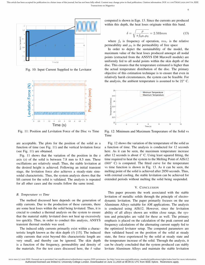
are acceptable. The plots for the position of the solid as afunction of time (see Fig. 11) and the vertical levitation force(see Fig. 11) are obtained.
Fig. 11 shows that the variation of the position in the zaxis (z) of the solid is between 7.8 mm to 8.5 mm. Theseoscillations are relatively small. Thus, the stable levitation atthe desired height is achieved. Following an initial transientstage, the levitation force also achieves a steady-state sinu-soidal characteristic. Thus, the system analysis shows that thelift current for the solid is validated. The analysis is repeatedfor all other cases and the results follow the same trend.
B. Temperature vs Time
The method discussed here depends on the generation ofeddy currents. Due to the production of these currents, thereare some heat loses within the solid being levitated. Thus, it iscrucial to conduct a thermal analysis on the system to ensurethat the material stably levitated does not heat up excessivelytoo quickly. Thus, in order to conduct this analysis, ANSYStransient thermal module was used.
The induced eddy currents primarily exist within a charac-teristic length known as the skin depth (δ) [15]. The inducededdy currents that exist beyond this characteristic length arevery small, and thereby can be ignored. The skin depthis a function of the frequency, permeability and density ofthe materials. For the test cases discussed here, the δ value
computed is shown in Eqn. 13. Since the currents are producedwithin this depth, the heat loses originate within this band.
δ =
√ρ
πf0µrµ0= 2.593mm (13)
where f0 is frequency of operation, mur is the relativepermeability and µ0 is the permeability of free space
In order to depict the sustainability of the model, themaximum value of the heat loses produced amongst all nodalpoints (extracted from the ANSYS EM Maxwell module) areuniformly fed to all nodal points within the skin depth of thedisc. This ensures that the temperature estimated is higher thanthe actual temperature distribution of the disc. The primaryobjective of this estimation technique is to ensure that even inrelatively harsh circumstances, the system can be feasible. Forthe analysis, the ambient temperature is assumed to be 22◦ C.
0 2 4 6 8 10 12Time (s)
22
22.5
23
23.5
24
24.5
25
Tem
pera
ture
(C
elci
us)
Minimum TemperatureMaximum Temperature
Fig. 12: Minimum and Maximum Temperature of the Solid vsTime
Fig. 12 shows the variation of the temperature of the solid asa function of time. The analysis is conducted for 12 secondshere. As it can be seen, the maximum temperature increaseafter 12 seconds is about 4◦ C. Using least squared fitting, thetime required to heat the system to the Melting Point of AlSi12(660◦ C) is computed. The fitted curve for the temperaturevs time function is shown in Fig. 13. As it can be seen, themelting point of the solid is achieved after 2850 seconds. Thus,with external cooling, the stable levitation can be achieved forextended periods without melting the solid being suspended.
V. CONCLUSION
This paper presents the work associated with the stablelevitation of metallic solids through the principle of electro-dynamic levitation. The paper primarily focuses on the useAluminum Alloys suitable for AM applications. The analysisis conducted using AlSi12. However, since the levitationability of all alloys shown are within close range, the sys-tem and principles are valid for these as well. The primaryemphasis is placed on the calculation of the peak current andfrequency calculations of the alternating current supply fed tothe optimized levitator setup. The computed parameters arethen validated based on the position of the solid at steadystate, the force experienced by the solid at steady state andthe temperature increase of the solid. Through the analysis, itcan be clearly concluded that the system produced can stablylevitate Aluminum Alloys and maintain the stable levitation
Authorized licensed use limited to: University College London. Downloaded on June 11,2020 at 08:09:31 UTC from IEEE Xplore. Restrictions apply.

0018-9464 (c) 2020 IEEE. Personal use is permitted, but republication/redistribution requires IEEE permission. See http://www.ieee.org/publications_standards/publications/rights/index.html for more information.
This article has been accepted for publication in a future issue of this journal, but has not been fully edited. Content may change prior to final publication. Citation information: DOI 10.1109/TMAG.2020.2997759, IEEETransactions on Magnetics
7
0 1000 2000 3000
Time (s)
0
200
400
600
800Te
mpe
ratu
re (
Cel
cius
)
Fig. 13: Fitted Curve (from Maximum Current) for Tempera-ture vs Time with Melting point of Al (660◦) plotted
for extended periods of time. A significant limitation of themethodology presented here is that the technique is onlyapplicable to electrical conducting materials. As stated insection II-B, the levitation ability of the part is dependent onthe electrical conductivity of the material. However, it can beconcluded that the system has found to be applicable withinthe AM environment using metallic alloys (e.g., AlSi12) tobuild the part. There is a strong dependence on the useof simulations through ANSYS Maxwell. However, giventhe high fidelity of the simulation results and the reliabilityof these simulations (depicted in Appendix A), the resultspresented are well grounded. Further experiments are to beconducted to validate the work presented through experimentaldata.
APPENDIX AFIDELITY OF SIMULATIONS THROUGH ANSYS
ANSYS Maxwell 2D and 3D software has played a verymajor role in the analysis presented. ANSYS Maxwell 3D -Eddy Current Module has been used to calculate the magni-tude and frequency of alternating current required for stablesuspension. ANSYS Maxwell 3d - Transient Module was usedto generate the plots as a function of time.
The simulation results are quite high fidelity and have beenproven to be very reliable in terms of mimicking real worldperformance of magnetic systems. For instance, the systempresented in [15] was simulated in ANSYS Maxwell and theresults of the simulation was compared to the results of thepaper.
[15] presents the levitation of a coil over an Aluminumdisc. The system consists of a single coil with 107 turns. Thecoil has a radial width of 2 mm (outer diameter = 5 mm andinner diameter = 3 mm) and an axial height of 1.6 mm. Thedimension of the disc is much larger than the coil (treatedas infinite). The disc was taken to have a radius of 500 mmand height of 10 mm. According to [15], it was determinedexperimentally that the current required to levitate the coil at
20 mm was 39 A at a frequency of 60 Hz. The results obtainedfrom the simulations are presented in fig. 14.
0 0.5 1
Time (s)
-5
0
5
10
15
20
Levi
tatio
n F
orc
e (N
)
0
5
10
15
20
25
Pos
ition
(m
m)
Fig. 14: Resulting plots from Simulations for the systemstudied in [15]
As it can be noted, the results of the simulations are quitesimilar to the experimental results presented. The coil levitatesat 20.5 mm. Thus, the results obtained from the simulation arewithin 2.5% of the experimental data presented. Thus, it canbe concluded that the simulations have a very high fidelity,thereby provide reliable data.
REFERENCES
[1] Frazier, W.E. J. of Materi Eng and Perform (2014) 23: 1917.https://doi.org/10.1007/s11665-014-0958-z
[2] A. Saboori, D. Gallo, S. Biamino, P. Fino, and M. Lombardi, “AnOverview of Additive Manufacturing of Titanium Components by Di-rected Energy Deposition: Microstructure and Mechanical Properties,”Applied Sciences, vol. 7, no. 9, p. 883, 2017.
[3] J.-Y. Lee, J. An, and C. K. Chua, “Fundamentals and applications of3D printing for novel materials,” Applied Materials Today, vol. 7, pp.120–133, 2017.
[4] Y. Huang, M. Ansari, H. Asgari, M. H. Farshidianfar, D. Sarker, M. B.Khamesee, and E. Toyserkani, “Rapid prediction of real-time thermalcharacteristics, solidification parameters and microstructure in laser di-rected energy deposition (powder-fed additive manufacturing),” Journalof Materials Processing Technology, vol. 274, p. 116286, 2019.
[5] Jonathan Meyer, “Substrate for additive manufacturing”, 14-Aug-2018[6] X. Liu, Y. Lu, Q. Zhang, and K. Zhang, “An Application of Eddy Current
Effect on the Active Detumble of Uncontrolled Satellite With Tilt AirGap,” IEEE Transactions on Magnetics, vol. 55, no. 12, pp. 1–11, 2019.
[7] H. Cho, D. K. Bae, H.-K. Sung, and J. Lee, “Experimental Study on theElectrodynamic Suspension System With HTSC and PM Halbach ArrayMagnets,” IEEE Transactions on Applied Superconductivity, vol. 18, no.2, pp. 808–811, 2008.
[8] Duan, Jiaheng, et al. “Analysis and Optimization of AsymmetricalDouble-Sided Electrodynamic Suspension Devices.” IEEETransactions on Magnetics, vol. 55, no. 6, 2019, pp. 1–5.,doi:10.1109/tmag.2019.2894709.
[9] W. A. Harkness and J. H. Goldschmid, “Free-Form Spatial 3-D PrintingUsing Part Levitation,” 04-Feb-2016.
[10] X.-W. Dai, R. Ludwig, and R. Palanisamy, “Numerical simulation ofpulsed eddy-current nondestructive testing phenomena,” IEEE Transac-tions on Magnetics, vol. 26, no. 6, pp. 3089–3096, 1990.
[11] P. Leonard and D. Rodger, “Finite element scheme for transient 3D eddycurrents,” IEEE Transactions on Magnetics, vol. 24, no. 1, pp. 90–93,1988.
Authorized licensed use limited to: University College London. Downloaded on June 11,2020 at 08:09:31 UTC from IEEE Xplore. Restrictions apply.

0018-9464 (c) 2020 IEEE. Personal use is permitted, but republication/redistribution requires IEEE permission. See http://www.ieee.org/publications_standards/publications/rights/index.html for more information.
This article has been accepted for publication in a future issue of this journal, but has not been fully edited. Content may change prior to final publication. Citation information: DOI 10.1109/TMAG.2020.2997759, IEEETransactions on Magnetics
8
[12] E. N.- Juszczak, R. Grzybowski, and J. Brudny, “Modelling of lossesdue to eddy currents and hysteresis in converter transformer cores duringfailure,” IEEE Transactions on Magnetics, vol. 31, no. 3, pp. 1718–1721,1995.
[13] Dolker, Eva-Maria, et al. “Velocity-Dependent Lorentz Force Evaluation:A Simulation Study.” IEEE Transactions on Magnetics, vol. 55, no. 6,2019, pp. 1–4., doi:10.1109/tmag.2019.2901579.
[14] E. Kriezis, T. Tsiboukis, S. Panas, and J. Tegopoulos, “Eddy currents:theory and applications,” Proceedings of the IEEE, vol. 80, no. 10, pp.1559–1589, 1992.
[15] M. Thompson, “Electrodynamic magnetic suspension-models, scalinglaws, and experimental results,” IEEE Transactions on Education, vol.43, no. 3, pp. 336–342, 2000.
[16] D. J. Griffiths, Introduction to electrodynamics. Cambridge, UnitedKingdom: Cambridge University Press, 2018.
[17] Fisk M. (2014) Induction Heating. In: Hetnarski R.B. (eds) Encyclopediaof Thermal Stresses. Springer, Dordrecht
[18] Nan, Wang, et al. “Physical Characteristics of Electromagnetic Levita-tion Processing.” Acta Physica Sinica (Overseas Edition), vol. 8, no. 7,1999, pp. 503–513., doi:10.1088/1004-423x/8/7/005.
[19] N. T. Aboulkhair, M. Simonelli, L. Parry, I. Ashcroft, C. Tuck, and R.Hague, “3D printing of Aluminium alloys: Additive Manufacturing ofAluminium alloys using selective laser melting,” Progress in MaterialsScience, vol. 106, p. 100578, 2019.
[20] Singh, Amrinder, et al. “Direct Laser Metal Deposition of Eutectic Al-SiAlloy for Automotive Applications.” TMS 2017 146th Annual MeetingExhibition Supplemental Proceedings The Minerals, Metals & MaterialsSeries, 2017, pp. 71–80., doi:10.1007/978-3-319-51493-2_8.
[21] K. Kempen, L. Thijs, J. V. Humbeeck, and J.-P. Kruth, “MechanicalProperties of AlSi10Mg Produced by Selective Laser Melting,” PhysicsProcedia, vol. 39, pp. 439–446, 2012.
[22] S. Siddique, M. Imran, E. Wycisk, C. Emmelmann, and F. Walther,“Fatigue Assessment of Laser Additive Manufactured AlSi12 EutecticAlloy in the Very High Cycle Fatigue (VHCF) Range up to 1E9 cycles,”Materials Today: Proceedings, vol. 3, no. 9, pp. 2853–2860, 2016.
[23] J.-P. Immarigeon, R. Holt, A. Koul, L. Zhao, W. Wallace, and J.Beddoes, “Lightweight materials for aircraft applications,” MaterialsCharacterization, vol. 35, no. 1, pp. 41–67, 1995.
[24] B. Ahuja, M. Karg, K. Y. Nagulin, and M. Schmidt, “Fabrication andCharacterization of High Strength Al-Cu Alloys Processed Using LaserBeam Melting in Metal Powder Bed,” Physics Procedia, vol. 56, pp.135–146, 2014.
Authorized licensed use limited to: University College London. Downloaded on June 11,2020 at 08:09:31 UTC from IEEE Xplore. Restrictions apply.