
Development of a high average current rf linac thermionic ...
12
Development of a high average current rf linac thermionic injector S. H. Gold, 1 A. Ting, 1 V. Jabotinski, 2 B. Zhou, 3 and P. Sprangle 1 1 Plasma Physics Division, Naval Research Laboratory, Washington, D.C. 20375, USA 2 Beam-Wave Research, Inc., Bethesda, Maryland 20814, USA 3 Research Support Instruments, Inc., Lanham, Maryland 20706, USA (Received 5 February 2013; published 1 August 2013) Thermionic electron guns are capable of operating at high average currents in a variety of vacuum electronic applications, including conventional microwave tubes, but have been replaced by laser photo- cathode injectors for most applications requiring high-brightness electron beams. However, while laser photocathode guns are capable of providing the very high-brightness beams, they provide an increased level of system complexity and do not extrapolate well to injectors for high average current applications requiring high beam quality. We are developing a 714 MHz injector based on a gridded thermionic electron gun for these applications. This paper presents an experimental study, computer simulations, and analysis of the performance of an existing gridded thermionic electron gun as an injector prototype, and a design concept for an improved injector configuration based on these results. DOI: 10.1103/PhysRevSTAB.16.083401 PACS numbers: 07.77.Ka, 29.27.Ac I. INTRODUCTION Radio-frequency linear accelerators are used to acceler- ate short bunches (microbunches) of electrons to high energy using the rf fields excited in standing-wave or traveling-wave structures. The first stage of an electron linear accelerator is an electron injector, beginning with a cathode that is the source of the electrons. The quality, bunch length, and timing of the electrons injected into the first rf cell are critical to determining the properties of the final high energy electron bunches that are generated by a complete accelerator system [1]. For applications that re- quire high electron beam quality, the final beam quality requirements in the interaction region can be traced back to requirements on the electron microbunches injected into the first cell of the rf accelerating system [2]. Electron injectors can use several different types of cathodes to generate the electrons that are accelerated in the first rf cavity [3,4]. One approach is to use a thermionic cathode located on the axis of the upstream wall of the first accelerating cell. This approach is capable of producing high average currents, since such cathodes can operate at high current density (up to 10 A cm 2 ) while filling every rf bucket of the linac. However, injectors using a simple thermionic cathode exposed to the rf fields of the first accelerating cavity do not provide a means to gate the electron emission. As a result, electrons will be emitted whenever the rf phase accelerates electrons from the cath- ode surface. One result is that there is a large energy spread in the electrons that exit the first rf cell, as well as a large spread in the rf phase angle at which electrons enter sub- sequent rf cells. In addition, there is a large population of electrons that are accelerated from the cathode, but do not exit the cell before the oscillating rf fields push the elec- trons back to the cathode or to the cavity wall. In an injector operating at high average current, this back- bombardment can damage the cathode and can constitute a significant thermal load on the cavity wall. For these reasons, it is desirable to gate the electron emission from the cathode into the first rf cavity. Direct gating of a thermionic cathode has been used in some low average current applications by carrying out the gating using a high voltage pulse applied to a gridded cathode as part of an injector that operates at a subhar- monic of the linac frequency, and then typically employing subharmonic bunching to increase the peak current in- jected into the linac [5–8]. Also, direct 1-GHz rf modula- tion of the grid has been employed [9], again followed by subharmonic bunching. However, operating the injector at the nth subharmonic of the linac frequency means that only every nth bucket of the linac will be filled, thus reducing the average current that the linac can deliver. Also, other means have been employed that involve slicing a short charge bunch from a longer electron pulse, and simply discarding the remainder of the electrons [10,11]. This latter approach is also not suitable for high average current injector applications. The most common current approach to gating is to generate electron bunches using emission from photocath- odes that are excited by laser radiation, with the electron emission controlled directly by the temporal structure of the laser pulse. Photocathodes can operate at high instan- taneous currents and provide electron bunches that have both high quality and high charge per microbunch. For these reasons, they are generally the preferred approach for Published by the American Physical Society under the terms of the Creative Commons Attribution 3.0 License. Further distri- bution of this work must maintain attribution to the author(s) and the published article’s title, journal citation, and DOI. PHYSICAL REVIEW SPECIAL TOPICS - ACCELERATORS AND BEAMS 16, 083401 (2013) 1098-4402= 13=16(8)=083401(12) 083401-1 Published by the American Physical Society
Transcript of Development of a high average current rf linac thermionic ...

Development of a high average current rf linac thermionic injector
S.H. Gold,1 A. Ting,1 V. Jabotinski,2 B. Zhou,3 and P. Sprangle1
1Plasma Physics Division, Naval Research Laboratory, Washington, D.C. 20375, USA2Beam-Wave Research, Inc., Bethesda, Maryland 20814, USA
3Research Support Instruments, Inc., Lanham, Maryland 20706, USA(Received 5 February 2013; published 1 August 2013)
Thermionic electron guns are capable of operating at high average currents in a variety of vacuum
electronic applications, including conventional microwave tubes, but have been replaced by laser photo-
cathode injectors for most applications requiring high-brightness electron beams. However, while laser
photocathode guns are capable of providing the very high-brightness beams, they provide an increased
level of system complexity and do not extrapolate well to injectors for high average current applications
requiring high beam quality. We are developing a 714 MHz injector based on a gridded thermionic
electron gun for these applications. This paper presents an experimental study, computer simulations, and
analysis of the performance of an existing gridded thermionic electron gun as an injector prototype, and a
design concept for an improved injector configuration based on these results.
DOI: 10.1103/PhysRevSTAB.16.083401 PACS numbers: 07.77.Ka, 29.27.Ac
I. INTRODUCTION
Radio-frequency linear accelerators are used to acceler-ate short bunches (microbunches) of electrons to highenergy using the rf fields excited in standing-wave ortraveling-wave structures. The first stage of an electronlinear accelerator is an electron injector, beginning with acathode that is the source of the electrons. The quality,bunch length, and timing of the electrons injected into thefirst rf cell are critical to determining the properties of thefinal high energy electron bunches that are generated by acomplete accelerator system [1]. For applications that re-quire high electron beam quality, the final beam qualityrequirements in the interaction region can be traced back torequirements on the electron microbunches injected intothe first cell of the rf accelerating system [2].
Electron injectors can use several different types ofcathodes to generate the electrons that are accelerated inthe first rf cavity [3,4]. One approach is to use a thermioniccathode located on the axis of the upstream wall of the firstaccelerating cell. This approach is capable of producinghigh average currents, since such cathodes can operate athigh current density (up to �10 A cm�2) while fillingevery rf bucket of the linac. However, injectors using asimple thermionic cathode exposed to the rf fields of thefirst accelerating cavity do not provide a means to gate theelectron emission. As a result, electrons will be emittedwhenever the rf phase accelerates electrons from the cath-ode surface. One result is that there is a large energy spreadin the electrons that exit the first rf cell, as well as a large
spread in the rf phase angle at which electrons enter sub-sequent rf cells. In addition, there is a large population ofelectrons that are accelerated from the cathode, but do notexit the cell before the oscillating rf fields push the elec-trons back to the cathode or to the cavity wall. In aninjector operating at high average current, this back-bombardment can damage the cathode and can constitutea significant thermal load on the cavity wall. For thesereasons, it is desirable to gate the electron emission fromthe cathode into the first rf cavity.Direct gating of a thermionic cathode has been used in
some low average current applications by carrying out thegating using a high voltage pulse applied to a griddedcathode as part of an injector that operates at a subhar-monic of the linac frequency, and then typically employingsubharmonic bunching to increase the peak current in-jected into the linac [5–8]. Also, direct 1-GHz rf modula-tion of the grid has been employed [9], again followed bysubharmonic bunching. However, operating the injector atthe nth subharmonic of the linac frequency means that onlyevery nth bucket of the linac will be filled, thus reducingthe average current that the linac can deliver. Also, othermeans have been employed that involve slicing a shortcharge bunch from a longer electron pulse, and simplydiscarding the remainder of the electrons [10,11]. Thislatter approach is also not suitable for high average currentinjector applications.The most common current approach to gating is to
generate electron bunches using emission from photocath-odes that are excited by laser radiation, with the electronemission controlled directly by the temporal structure ofthe laser pulse. Photocathodes can operate at high instan-taneous currents and provide electron bunches that haveboth high quality and high charge per microbunch. Forthese reasons, they are generally the preferred approach for
Published by the American Physical Society under the terms ofthe Creative Commons Attribution 3.0 License. Further distri-bution of this work must maintain attribution to the author(s) andthe published article’s title, journal citation, and DOI.
PHYSICAL REVIEW SPECIAL TOPICS - ACCELERATORS AND BEAMS 16, 083401 (2013)
1098-4402=13=16(8)=083401(12) 083401-1 Published by the American Physical Society

high-brightness applications [3,4,12–16]. However, the useof laser photocathodes is a complicated and expensiveapproach that does not easily scale to robust systems toproduce high average beam currents, since there are limi-tations of the drive lasers as well as limitations due to thethermal loading and lifetime of the photocathodes. Somework has also taken place to partially gate the emissionfrom thermionic cathodes by using a dual-frequency cavitywith appropriate phasing of the two modes [17,18], tophotogate the emission from thermionic cathodes by add-ing laser irradiation [19,20], and to make use of ballisticbunch compression of the bunches produced by ungatedthermionic cathodes [21]. References [22,23] compareself-amplified spontaneous emission in an undulator frominjectors either using a photocathode electron gun or usinga thermionic rf gun combined with alpha magnet compres-sion, and Ref. [24] presents a comparison of thermionic,photogated thermionic, and photocathode injectors in thecontext of THz radiation generation. Also, a dual-frequency cavity combined with a field-emitter array(FEA) has been proposed, with the combination of twoharmonically related frequencies and appropriate ampli-tude and phase relationships combining with the nonlinearemission characteristics of the FEA to permit control of theemission phase [25].
As an alternative to these various methods of gating theemission, we are exploring an approach that uses a griddedthermionic electron gun that combines a high current,robust thermionic emitter with direct rf modulation of thegrid at the linac frequency and higher harmonics in order toprovide a high current injector that provides the gatingrequired for injection into the proper rf phase of the firstrf accelerating cavity. In this paper, we evaluate the poten-tial of a gridded thermionic electron gun as the first stage ofan accelerator injector system, as proposed in Ref. [2].
The plan of our program is to carry out experimentalmeasurements and theoretical investigations on a commer-cially available gridded thermionic electron gun driven at�700 MHz, and to study electron bunch length, bunchcharge, and transverse beam emittance as a function ofthe negative bias between the grid and cathode (Vgrid) and
the rf drive power at gun voltages of 30–35 kV. Also, wewant to test the effects of adding third harmonic drive to thecathode-grid circuit to reduce the electron bunch length.These measurements are then compared to simulationsusing the electron gun code MICHELLE [26] in order tomodel the diagnostics and to benchmark the simulations.MICHELLE simulations are also used to study an alternative
electron gun design that can have improved transverseemittance and shorter electron bunch length.
The electron injector for a high average power rflinac should produce high charge electron bunches withlow energy spread ready for injection to the linac. Typicalbeam parameters for such an injector are a bunch charge of�1 nC at a repetition rate of �700 MHz in cw operation.
Other proposed target parameters are a normalized trans-verse rms emittance of "? < 15 mmmrad and a rms bunchduration of �b < 50 ps.
II. EXPERIMENTAL SETUP
The goal of the experiment is to characterize the per-formance of a gridded thermionic electron gun that issimilar to the electron gun used in the production ofinductive output tube amplifiers (IOTs) [27]. It incorpo-rates a dispenser cathode and a pyrolytic graphite grid thatcan modulate the cathode emission at frequencies greaterthan 1 GHz. In an IOT, the modulated electron beam wouldthen interact in a resonant output cavity in order to generatetens of kilowatts of rf power at the drive frequency at up to100% duty factor. Here, the gun is being used as theprototype of an advanced thermionic gun that will beoptimized for minimum bunch length and minimum nor-malized emittance while operating at �1 nC microbunchcharge in fully cw operation at �700 MHz.A schematic cross sectional diagram of the electron gun
is shown in Fig. 1. The gun incorporates a 3-cm diametercathode and a closely spaced pyrolytic graphite grid that isbiased negatively with respect to the cathode. The center ofthe cathode is �5 cm from the end of the gun outputflange. A central hole �7 mm in diameter passes throughthe cathode and the grid wires, and is intended to reducecathode damage due to ion back-bombardment. As part ofan IOT, the electron gun would normally operate withnegative DC high voltage on the cathode with respect tothe anode, which is at ground potential, and with theemission controlled by the DC bias of the grid with respectto the cathode and by the rf drive of the cathode-gridcircuit. However in our experiment, the cathode-grid cir-cuit is pulsed to a negative high voltage (Vcathode) withrespect to the grounded anode of up to �36 kV using ahigh voltage modulator. The cathode heater is powered bya 60 Hz AC feed that floats on the high voltage pulse, andan adjustable negative grid bias (Vgrid) of up to �180 V
FIG. 1. Schematic diagram of the gridded thermionic electrongun.
GOLD et al. Phys. Rev. ST Accel. Beams 16, 083401 (2013)
083401-2

with respect to the cathode also floats with the high voltagepulse. The negative bias on the grid, which suppresseselectron emission, is combined with direct rf modulationof the cathode-grid circuit via a coaxial feed line toproduce a high current electron beam that is bunched atthe rf frequency. The rf modulation is introduced through acoaxial line that feeds the cathode-grid circuit through ahigh voltage coaxial break. Beyond the break, the coaxopens up to enclose the cathode and then terminates at thegrid, with the cathode-grid gap capacitively loading theend of the coaxial line. The goal of our experiments is tocharacterize the properties of the electron beam, first bydepositing the electrons in a Faraday cup placed close tothe output flange, in order to measure the temporal widthand charge of electron bunches, and second by using slit-based optical measurements to determine the electronbeam emittance.
The high voltage power supply for the IOT gun is a70 kV Rockwell hard tube modulator with an output pulsewidth that is variable up to�15 �s. For these experiments,the voltage was limited to Vcathode � 36 kV and the outputpulse width was set at its maximum. The heater coil insidethe cathode assembly is not compensated by a centerreturn. As a result, it produces stray magnetic fields atthe cathode surface that oscillate at 60 Hz, producing avariation in the beam from the gun. In order to avoid thiseffect, the modulator timing was synchronized with thezero crossing of the heater current measured at the cathode.Experimental measurements were typically performed latein the pulse, in order to minimize the effect of gun turn-ontransients and voltage ringing. These transients occur be-cause the high voltage feed to the cathode is essentially ahigh voltage lead, rather than a transmission line, and is notmatched to the cathode circuit. (Actually, there are threeseparate high voltage leads connected to the gun, all shar-ing an identical high voltage pulse from the modulator, butcarrying separate interlead voltages to power the AC heatercircuit and to created a DC bias of the grid with respect tothe cathode bias, both of which float at the cathode poten-tial.) In the case of rf drive, a 1-�s rf pulse was applied tothe grid circuit using the same timing near the end of thehigh voltage pulse, and fast time scale measurements weremade in a window within the rf pulse.
Figure 2 shows the experimental setup used to measurethe length and charge of the electron bunches from thegun. The rf drive for the cathode-grid circuit was producedby a Technical Services Laboratory Model 1710 dual-frequency amplifier that provides up to �500 W of outputat a fundamental frequency tunable between 700 and714 MHz as well as up to �450 W at the third harmonicof the fundamental frequency. Both output signals arelocked to a single 100 kHz crystal oscillator, with separatecontrols of the two output power levels. A phase adjuster inthe low frequency line allows control of the relative phasebetween the fundamental and third harmonic signals.Finally, the two signals are combined inside the chassisto feed a single coaxial output. The output power levels areread out directly from the amplifier using an internal peakpower meter, and the rf is also monitored using a bidirec-tional coupler that is read out directly on a fast digitaloscilloscope. The cathode-grid circuit is fed by a 50 �Heliax cable connected to the coaxial output of the ampli-fier. The coaxial feed from the amplifier employs separatelow and high frequency slug tuners in a series configurationfor impedance matching both signals into the electron gun.For reasons of convenience, we chose to carry out theseexperiments at 714 and 2142 MHz.The electron bunches from the gun were collected on the
copper cone of a fast Faraday cup (Princeton ScientificCorp.) with �50 ps time resolution. The Faraday cupincludes a grid that is biased negative with respect to thecopper cone in order to capture secondary electrons gen-erated by the impact of beam electrons on the copper cone.The Faraday cup was placed as close as possible (�3 cm)to the gun output flange in order to limit bunch spreadingdue to velocity spread and space-charge effects. The cur-rent collected by the Faraday cup passed through calibratedattenuators and was recorded by a Tektronix DSA 71604B16-GHz digital oscilloscope, with the signal line termi-nated in 50 �. The Faraday cup remains near groundpotential, and is separated from ground only by the voltagedrop through the 50 � termination. The experimental var-iables were the gun voltage, the grid bias voltage Vgrid, and
the level of fundamental and third harmonic rf drive. Inaddition, the heater power was controlled to ensure repro-ducible emission from the cathode.
BidirectionalCoupler
Low-f Slug Tuner
High-f Slug Tuner
Electron Gun
Dual FrequencyAmplifier
Coaxial Transmission Line
HeliaxCable
Fast Faraday
Cup
Cathode + Grid Anode
FIG. 2. Schematic diagram of the experimental setup for bunch length measurements.
DEVELOPMENT OF A HIGH AVERAGE CURRENT RF . . . Phys. Rev. ST Accel. Beams 16, 083401 (2013)
083401-3

III. DISCUSSION OF THE FARADAY CUP DATA
Figure 3 shows the measured current from the Faradaycup as a function of Vgrid with Vcathode ¼ �31 kV. The
peak current at Vgrid ¼ 0 V is�2:5 A, which according to
our simulations corresponds to mixed space-charge andtemperature-limited emission from the cathode. However,as Vgrid is made increasingly negative, the emission from
the cathode becomes space-charge limited, and falls rap-idly until about Vgrid ¼ �70 V. Simulations show that
emission from the face of the cathode through the gridshould cut off sharply at this value of grid bias. However,the experimental data shows that the emission does not cutoff at this value of Vgrid. Instead, it continues to fall
steadily, but at a slower rate than at lower values of gridbias, and there is still 3.6 mA of current at Vgrid ¼ �126 V.
This behavior indicates that there is a source of unwantedemission in the gun that is not effectively controlled by thegrid bias.
One possible source of the unwanted emission is emis-sion from the grid wires, which can become contaminatedwith barium from the hot cathode and may be hot enoughto emit. However, this explanation is not well supported bythe data, which shows that the emission continues to fallmonotonically as the grid bias is increased above thepredicted cutoff value. Emission from the grid wires shouldnot be affected in this way by the grid bias, since thechange in voltage between the grid and anode is less than1%.
The second possibility is emission from the edge surfaceof the central hole through the cathode, which can readilybe contaminated with barium, and which is clearly hotenough to emit, being at the same temperature as the restof the cathode. Electron trajectories originating in thisregion and leaking through the central hole in the gridwires would still be affected by the grid potential, thoughto a lesser extent than emission from the face of the
cathode, and should decrease monotonically as Vgrid is
made more negative. This mechanism explains the datain Fig. 3, as shown in the dashed curve that is derived froma simulation that includes emission from the edge surfaceof the central hole through the cathode, and it also shedslight on the results of rf-gated Faraday cup measurementsthat are shown in later figures. In addition, further evidenceof this phenomenon based on optical diagnostics will bepresented later in this paper.The phenomenon of current escaping through the central
hole in the grid wires was discussed by Wright and co-workers as the source of interbunch emission in the pres-ence of rf grid drive, based on their MICHELLE simulationsof a similar IOT electron gun [27]. In the context of an IOTamplifier, this phenomenon will result in some electronsentering the output cavity in the accelerating phase of thecavity fields, and gaining energy as they transit the outputcavity, resulting in increased x-ray production when theyare deposited in the IOT collector. However, Ref. [28]analyzed interbunch current only in the presence of rfdrive. Our results, as well as the corresponding MICHELLE
simulations, in which the edge of the cathode hole ispermitted to emit, show that there is also a DC componentof current emerging from the center hole with no rf driveand in the presence of strong negative grid bias.In the IOT application, the gridded electron gun is
typically used to create �180 degree modulation of theelectron beam, in order to efficiently generate high powerrf in the output cavity [29]. However, the injector applica-tion requires the generation of much shorter electronbunches for injection into the optimum phase of a set ofrf accelerating cavities. In the presence of a negative valueof Vgrid combined with a single-frequency rf drive, the
cathode will emit electrons whenever the instantaneousvalue of the grid voltage is positive with respect to thecathode. As a result, the length of the electron bunches canbe controlled by the ratio of the peak rf amplitude appliedto the grid and the value of Vgrid. This simple picture
ignores transit-time effects in the cathode-grid gap.Nevertheless, as that ratio is decreased towards one, thebunch lengths are reduced, the peak bunch current isreduced, and for both reasons, the charge per bunch isalso reduced.One means to reduce the bunch length without simulta-
neously reducing the peak bunch current is to change the rfmodulation waveform from sinusoidal to a more peakedwaveform. One practical way to accomplish this is to addhigher harmonic modulation to the grid drive. We chose toinvestigate third harmonic modulation, in this case at2142 MHz, that is locked in phase with the fundamentalharmonic modulation at 714MHz.With the correct relativephase between the two signals, the rf modulation willbecome more peaked, and thus shorter bunches will inprinciple be produced at the same peak rf amplitude onthe grid. In order to carry out this procedure, a special
FIG. 3. Measured beam current versus Vgrid for Vcathode ¼�31 kV. The solid line is from a MICHELLE simulation of theelectron gun, with emission only from the face of the cathode.The simulation model takes into consideration temperature-limited emission from the cathode at 1095 K. The dashed lineincludes emission from both the face of the cathode and the edgesurface of the central hole through the cathode.
GOLD et al. Phys. Rev. ST Accel. Beams 16, 083401 (2013)
083401-4

dual-frequency amplifier was purchased for this experi-ment, as described earlier in this paper.
One experimental question that needed to be addressedwas to establish that the 2142MHz signal at the input to theelectron gun would cause effective rf modulation of thevoltage across the cathode-grid gap. Figure 4 addresses thisissue. It shows the measured Faraday cup waveforms cor-responding to single-frequency modulation at 714 and2142 MHz. The 714 MHz rf modulation of the grid pro-duces strong modulation of the current measured by theFaraday cup, with a peak current of�2:2 A and 0.9 nC perbunch. However, there is also evidence of interbunch cur-rent, as indicated by the downward shift of the signal fromthe baseline of the trace, which is indicated by the pink doton the left axis. This current is believed to be related to theunmodulated current emitted from the central cathodehole, as discussed with reference to Fig. 3. The2142 MHz modulation also produces a modulation of thecurrent measured by the Faraday cup, thus demonstratingthat the 2142 MHz modulation is appearing across thecathode-grid gap. However in this case the DC component,or interbunch current, is much larger than the modulatedcurrent. In this case, the baseline of the trace is indicated bythe green dot on the left axis. This less effective bunchingmay be due to transit-time effects in the gap between thecathode and grid, which are more significant at the higherfrequency. Also, the peak microbunch current of 110 mA issubstantially lower than the 2.2 A current measured at714 MHz, even though the Vgrid is less negative and the
rf drive is substantially higher. In addition to possibletransit-time effects, this appears to be due to the lesseffective coupling of rf power into the cathode-grid gap.
In order to estimate the effective coupling of an rf signalinto the cathode-grid gap, we used a simple model of the rfinput circuit as a 50 � coaxial transmission line driving apurely capacitive load. (There will also be a resistivecomponent when an electron beam is generated.) The
cathode-grid region was modeled as two parallel 3-cmdisks separated by 250 �m, resulting in an estimatedcapacitance of C ¼ 25 pF. The impedance of the capacitoris then ði!CÞ�1, where ! ¼ 2�f, and f is either 714 or2142 MHz. In this case, for 100 Wof rf drive, the cathode-grid voltage would be approximately 51 Vat 714 MHz and8.5 V at 2142 MHz. These calculations do not include theeffect of the slug tuners in the transmission line, which arealways adjusted to minimize the reflected signal from theelectron gun at both frequencies. However, they do suggestthat the effective coupling to the cathode-grid gap will besubstantially lower for the third harmonic signal.The next test was to employ combined modulation of the
cathode-grid circuit at both 714 and 2142 MHz. To opti-mize the combined waveforms, the relative phase of thetwo single-frequency components was adjusted to producethe shortest effective electron bunch lengths. Figure 5
FIG. 4. Measured Faraday cup current (IFC) for single-frequency 714 MHz (left) and 2142 MHz (right) grid drive. For the left-handdata set, the parameters are Vcathode ¼ �24 kV, Vgrid ¼ �90 V, and�100 W at 714 MHz producing a 408 ps FWHM (�170 ps rms)
micropulse with peak current �2:2 A and 0.9 nC per bunch. For the right-hand data set, the parameters are Vcathode ¼ �24 kV,Vgrid ¼ �63 V, and �300 W at 2142 MHz, producing a peak current of �110 mA. The colored dot on the left axis associated with
each waveform shows the associated baseline of the trace. Also shown are the incident and reflected rf waveforms, rfin and rfout.
FIG. 5. Measured Faraday cup current, IFC, for combined firstand third harmonic modulation of the electron gun. The parame-ters are Vcathode ¼ �36 kV, Vgrid ¼ �90 V, with �540 W at
714 MHz and �450 W at 2142 MHz. The microbunches are325 ps FWHM (135 ps rms), with 2.81 A peak current and�0:91 nC per bunch. Also shown are rfin and rfout.
DEVELOPMENT OF A HIGH AVERAGE CURRENT RF . . . Phys. Rev. ST Accel. Beams 16, 083401 (2013)
083401-5

shows the Faraday cup measurements for Vcathode ¼�36 kV, Vgrid ¼ �90 V, with �540 W at 714 MHz and
�450 W at 2142 MHz. The microbunches are 325 psFWHM (�135 ps rms), with 2.81 A peak current and�0:91 nC per bunch. Note that rms bunch durations arecalculated assuming a Gaussian waveform with the
measured value of FWHM. As noted for the previousdata, a small level of DC, or interbunch current, persists.Figure 6 shows a MICHELLE simulation of the operation
of the electron gun for parameters corresponding to Fig. 5,including first and third harmonic rf drive. However, sincethere is no direct experimental determination of the rfvoltages in the cathode-grid gap, these voltages were setto U1 ¼ 69 V and U3 ¼ 23 V to provide a good fit to thedata. Figure 6 (top) shows the emission from the cathode,which peaks at more than 6 A, with 1.1 nC charge perbunch. The FWHM of the cathode current bunch is 160 ps,and the rms width is 74.7 ps. Figure 6 (center) shows thebunch shape at the position of the Faraday cup (8 cm fromthe center of the cathode). Here, the peak bunch current is2.96 A, with 0.95 nC charge per bunch. Also, the FWHM ofthe bunch is 301 ps. The rms bunch width is 160 ps, but isstrongly influenced by the tail of the bunch, which corre-sponds to interbunch current. Note that the first twobunches are not typical, and the bunch is still evolving tothe shape shown in the third and subsequent bunches.Figure 6 (bottom) shows a comparison of the third bunchto the bunches measured in Fig. 5.One means to shorten the length of the electron bunches
is to employ higher negative values of Vgrid. Figure 7 shows
data for Vgrid ¼ �100 V (left) and Vgrid ¼ �125 V
(right). In order to optimize the bunches, the applied powerat 714 MHz was reduced to �200 W, while the same�450 W was applied at 2142 MHz. For Vgrid ¼ �100 V,
the electron bunches are 235 ps FWHM (� 98 ps rms) andthe peak bunch current is 580 mA, corresponding to�135 pC per bunch. For Vgrid ¼ �125 V, the bunch
length is reduced to 190 ps FWHM (80 ps rms), but thepeak bunch current drops to 74 mA, corresponding to only14 pC per bunch. The rapid falloff of peak bunch currentand charge per bunch at higher levels of negative grid biasshows the limitation of this approach when applied to theexisting electron gun. However, these measurements alsodocument the capability of the Faraday cup to measurethese short bunches, indicating that the measured bunchshapes shown in Fig. 5 should not have been broadened bythe diagnostics.
FIG. 7. Faraday cup data for combined first and third harmonic modulation of the electron gun and higher negative grid bias forVcathode ¼ �36 kV, �200 W at 714 MHz and �450 W at 2142 MHz. The left traces correspond to Vgrid ¼ �100 V; the right traces
correspond to Vgrid ¼ �125 V.
FIG. 6. MICHELLE simulation of the bunched beam for opera-tion corresponding to Fig. 5. (top) Emitted current from thecathode; (center) current reaching the Faraday cup; (bottom)comparison of simulation and experimental data from Fig. 5.
GOLD et al. Phys. Rev. ST Accel. Beams 16, 083401 (2013)
083401-6

In order to examine the effect of adding 2142 MHzmodulation to the grid, we took a set of data at Vcathode ¼�36 kV and Vgrid ¼ �117 V in which the peak micro-
bunch current was set to 0.6 A with only 714 MHz modu-lation applied, and then various levels of 2142 MHzmodulation were added, and the 714 MHz modulationdecreased, in order to maintain 0.6 A of peak microbunchcurrent. The results are shown in Fig. 8. With no thirdharmonic drive, approximately 165 W of power at714 MHz was required, resulting in an rms bunch widthof �112 ps. The required first harmonic power dropsmonotonically as the third harmonic power is increased,and is reduced to �120 W with �200 W at third har-monic, resulting in a microbunch length of �96 ps rms.Neither the first harmonic power required to produce 0.6 Apeak bunch current at this value of negative grid bias northe rms bunch length change much when the third har-monic drive is further increased in steps up to �475 W.This data demonstrates that increasing the ratio of third tofirst harmonic power can help shorten the rms length of the
electron bunches for a fixed value of the peak microbunchcurrent.Figure 9 shows a plot of peak microbunch current and
microbunch length versus the power applied at 714 MHzwith the 2142 MHz power set at�400 W and the grid biasset to Vgrid ¼ �108 V. Both the bunch length and the peak
microbunch current increase as the first harmonic drivepower is increased.
IV. DISCUSSION OF THE EMITTANCE DATA
Aside from bunch length and bunch charge, the remain-ing critical parameter for the bunches produced by theelectron gun is their transverse emittance. For our lowenergy beam, we chose to employ a slit-base measurement[30–32], in which a 100 �m horizontal tantalum slit wasscanned across the beam using a vertical translator and theelectrons passing through the slit were intercepted by aYAG:Ce fluorescent screen. The fluorescent screen wasalso mounted on a vertical translator, in order to keep itcentered on the resulting electron trajectories. In turn, thefluorescent screen was imaged and recorded using a digitalCCD camera (FOculus camera model FO531TB) con-trolled by LABVIEW
TM software. The camera was triggeredelectronically. The exposure time was set to�3 �s, whichpermitted the camera to discriminate against emission thatdid not occur during the typical 1-�s rf drive pulse. Thelow beam energy and the beam divergence make it difficultto carry out accurate measurements, since the most diver-gent electron trajectories may intercept the wall of thevacuum vessel before reaching the slit plane, and sometrajectories through the slit may also intercept the wallbefore reaching the YAG screen. Several different experi-mental setups were used, in an attempt to optimize theacceptance of divergent electron trajectories.Figure 10 shows a schematic of the final experimental
setup that was employed. In this setup, a solenoidal lenswas added to help collimate the beam, thus ensuring thatmore of the beam reached the slit plane, and that more ofthe electrons that passed through the slit reached the YAGscreen. The effective geometry from the gun up to the slitplane is shown in Fig. 11, which also shows a MICHELLE
simulation of the electron trajectories from the gun, bothwithout lens current (center), and with a lens current of1.65 A (top). In these simulations, the gun is modeled forVcathode ¼ �32 kV and Vgrid ¼ �90 V with only first har-
monic rf drive applied. Since we cannot directly measurethe grid modulation amplitude resulting from a particular rfpower from the amplifier, the rf modulation of the cathode-grid gap was adjusted in the simulation to produce a peakmicrobunch charge of �0:75 nC. Figure 11 shows thateven at Ilens ¼ 1:65 A, some electron trajectories are lostto the wall before reaching the slit plane. In examiningFig. 11, it is important to note that the trajectories do notcarry equal amounts of charge. Figure 11 (bottom) shows asimulation of the trajectories with no lens current, but with
FIG. 8. The rms bunch length and first harmonic power versusthird harmonic power at 0.6 A peak microbunch current.
FIG. 9. Peak current and microbunch length versus power at714 MHz.
DEVELOPMENT OF A HIGH AVERAGE CURRENT RF . . . Phys. Rev. ST Accel. Beams 16, 083401 (2013)
083401-7
the emission from the edge of the cathode hole suppressed.A comparison of the bottom and center simulations showsthe affect of emission from the edge of the cathode hole increating interbunch current.
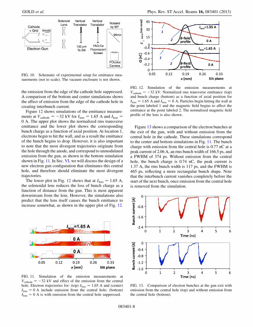
Figure 12 shows simulations of the emittance measure-ments at Vcathode ¼ �32 kV for Ilens ¼ 1:65 A and Ilens ¼0 A. The upper plot shows the normalized rms transverseemittance and the lower plot shows the correspondingbunch charge as a function of axial position. At location 1,electrons begin to hit the wall, and as a result the emittanceof the bunch begins to drop. However, it is also importantto note that the most divergent trajectories originate fromthe hole through the anode, and correspond to unmodulatedemission from the gun, as shown in the bottom simulationshown in Fig. 11. In Sec. VI, we will discuss the design of anew electron gun configuration that eliminates this centralhole, and therefore should eliminate the most divergenttrajectories.
The lower plot in Fig. 12 shows that at Ilens ¼ 1:65 A,the solenoidal lens reduces the loss of bunch charge as afunction of distance from the gun. This is most apparentdownstream from the lens. However, the simulations alsopredict that the lens itself causes the bunch emittance toincrease somewhat, as shown in the upper plot of Fig. 12.
Figure 13 shows a comparison of the electron bunches atthe exit of the gun, with and without emission from thecentral hole in the cathode. These simulations correspondto the center and bottom simulations in Fig. 11. The bunchcharge with emission from the central hole is 0.77 nC at apeak current of 2.06 A, an rms bunch width of 166.5 ps, anda FWHM of 374 ps. Without emission from the centralhole, the bunch charge is 0.74 nC, the peak current is1.37 A, the rms bunch width is 117 ps, and the FWHM is465 ps, reflecting a more rectangular bunch shape. Notethat the interbunch current vanishes completely before thestart of the next bunch, once emission from the central holeis removed from the simulation.
FIG. 10. Schematic of experimental setup for emittance mea-surements (not to scale). The vacuum enclosure is not shown.
FIG. 11. Simulation of the emission measurements atVcathode ¼ �32 kV and effect of the emission from the centralhole. Electron trajectories for: (top) Ilens ¼ 1:65 A and (center)Ilens ¼ 0 A include emission from the central hole; (bottom)Ilens ¼ 0 A is with emission from the central hole suppressed.
FIG. 12. Simulation of the emission measurements atVcathode ¼ �32 kV. Normalized rms transverse emittance (top)and bunch charge (bottom) as a function of axial position forIlens ¼ 1:65 A and Ilens ¼ 0 A. Particles begin hitting the wall atthe point labeled 1 and the magnetic field begins to affect theemittance at the point labeled 2. The normalized magnetic fieldprofile of the lens is also shown.
FIG. 13. Comparison of electron bunches at the gun exit withemission from the central hole (top) and without emission fromthe central hole (bottom).
GOLD et al. Phys. Rev. ST Accel. Beams 16, 083401 (2013)
083401-8

Figure 14 shows a summary of the results of slit-basedemittance measurements for Vcathode ¼ �32 kV, Vgrid ¼�90 V, and �250 W of rf drive at 714 MHz. Except forthe values of Ilens, these experimental parameters corre-spond closely to the simulations shown in Figs. 11 and 12.The highest value of the measured normalized transverserms emittance, as a function of magnet current, is�15 mmmrad, somewhat lower than predicted by thesimulations. Also, the measured emittance drops off athigher values of the magnet current, while the simulationssuggest that the emittance should increase. This may resultfrom experimental factors that affect the measurement,including (1) the possibility that electron trajectoriesthrough the slit intercept the wall of the vacuum vesselbefore reaching the YAG screen and (2) effects due to thefinite dynamic range of the optical measurements, whichmay result in a faint beam halo not being recorded by themeasurement system.
An explanation of the DC current at high negative valuesof Vgrid that are reported from the Faraday cup measure-
ments was provided by optical measurements of the beamthat were recorded as part of the slit-based emittancemeasurements that included the use of a solenoidal lensto collimate the beam. With the slit on or near the beamaxis, and Vgrid ¼ �90 V, the slit image was measured on
the YAG screen at several different values of the magnetcurrent while rf drive was present. In most cases, only thedownstream image of the slit was recorded with the trans-verse spread of the slit image related to the beam emit-tance. However, at a small range of values of the magnetcurrent, a small circle (� 4-mm diameter) appeared on theYAG in addition to the slit image (see Fig. 15); when the rfdrive was turned off, only the circle remained. The circlecould be brought into sharp focus on the YAG at 1.15 A ofsolenoid current. This indicated that the source of theelectron trajectories should correspond to a well-defined
feature on the cathode whose emission was not stronglysuppressed by the large negative values of Vgrid. The only
candidate feature is the edge of the central hole in thecathode. This region could emit electrons because of ba-rium migration from the face of the cathode, and electrontrajectories originating from this region could easily passthrough the hole in the center of the grid pattern.Since the focal length of the lens is known at the electron
energy and magnet current employed, the electron energyis constant when in the field of the magnet, and the distancefrom the lens to the YAG is also known, one can estimatethe distance to the apparent source of the electron trajecto-ries imaged onto the circle assuming the thin lens approxi-mation and using Eq. (1) [33]:
f ¼ 4Rdz½qBzð0; zÞ=�mevz�2
: (1)
Here, Bz is the axial magnetic field of the focusing magnetas a function of position along the axis, � is the relativisticfactor of the electrons, me is the electron mass, and vz isthe electron axial velocity. The integration is performedalong the axis through the region where the magnetic fieldis nonzero. Using the focal length of the magnetic lens for32 keV electrons, it was determined that the apparentsource of the electron trajectories was �30 cm behindthe cathode, a physical location that clearly cannot emitelectrons. The explanation for this is that the electrontrajectories emitted from the inner edge of the cathodehole have a strong radial component, but are bent stronglyin the vicinity of the cathode until they are close to paraxialstraight lines as they exit the gun. The lens formula projectsthose lines back to their apparent source, which is wellbehind the plane of the cathode hole.
FIG. 14. Measured emittance versus solenoid current forVcathode ¼ �32 kV, Vgrid ¼ �90 V, and �250 W of rf drive at
714 MHz.
FIG. 15. Image of YAG plate at Ilens ¼ 1:15 A with a 100-�mTa slit on the beam axis, showing the circular beam patternresulting from emission from the central hole in the cathode. Thefaint horizontal line is produced by the residual electrons emittedfrom the entire cathode surface and passing through the slit.
DEVELOPMENT OF A HIGH AVERAGE CURRENT RF . . . Phys. Rev. ST Accel. Beams 16, 083401 (2013)
083401-9

V. IMPROVED ELECTRON GUN WITHCATHODE INTEGRATED INTO THE
ACCELERATING CAVITY
The experimental measurements presented earlier in thispaper demonstrate the capabilities of a gridded thermioniccathode as the first stage of an electron injector, but alsoshowed that the existing electron gun, which was designedfor an entirely different application, falls somewhat shortof the typical emittance and bunch length parameters thatare required for some rf linac application. The sameMICHELLE/ANALYST [26,34] code combination that was
used to model the existing gun was also used to design anew improved gun that could be capable of meeting thoserequirements. Some of the changes are straightforward,such as removing the central hole to eliminate the inter-bunch current, and reducing the cathode diameter in orderto lower the emittance, which requires operating at highermean emission current density. However, the next step wasto envision an electron gun in which the initial DC accel-eration between the grid plane and the anode, prior toinjection into an rf cavity, is replaced by acceleration usingthe rf fields of the first cavity. Some preliminary work onthis concept was reported in Ref. [35].
The basic concept of this novel rf-gated thermionicelectron injector is shown in Fig. 16. It has a cylindricalrf accelerating cavity with the thermionic electron gunmounted in the first end wall on the cavity axis. Radio-frequency power is fed into the cavity through side powerports (not shown in the picture) and excites the TM010
resonant mode of the cavity. The E field of the mode hasits maximum on the cavity axis and accelerates the electronbunches extracted from the cathode through the grid. Thegun has a concave spherical cathode and rf modulated grid,with coaxial grid drive for rf excitation of the cathode-gridgap. A positive bias potential U0 relative to the grid is
applied to the cathode and prevents emission if no rfexcitation voltage U1 is applied across the grid to cathoderegion. Radio-frequency excitation of the coaxial griddrive produces rf modulation of the voltage across thecathode beam extraction region. The rf excitation can bethe first harmonic of the frequency f of the main accel-erating cavity TM010 resonant mode or can include higherharmonics of this frequency. To the right of the grid, cavityrf fields accelerate the electron bunches created by thecathode and grid.The amplitude Un of the rf excitation is selected to
provide the electric field for extraction of electron bunchesof the required charge and duration. Higher positive biasvoltage U0 in general leads to shorter bunch duration andalso requires higher harmonic rf voltage to keep the bunchcharge unchanged. The grid to cathode spacing is selectedto keep all the DC and rf E fields below the voltagebreakdown threshold, e.g. 70 kV=cm. In addition the spac-ing determines the rf power needed to excite the gap. Oursimulations show that the grid to cathode spacing has littleeffect on the emittances that are attainable. The size of thegrid wires affects both the emittance of the electron beamand the structural strength of the grid. A grid with thinnerwires produces smaller distortion of the E field and there-fore allows smaller emittance. However, the grid wiresmust remain thick enough for structural integrity.The key parameters responsible for the bunch properties
and control are the DC bias voltage and different combi-nations of the harmonic amplitudes and phases. This in-cludes the simplest case with only first harmonic for thegrid rf drive excitation. Higher order harmonics fundamen-tally allow shorter electron bunches. However, shorterbunches require higher peak currents to achieve the samemicrobunch charge, and thus either a larger cathode di-ameter or higher peak current density from the cathodesurface. In turn, a larger cathode diameter will tend toincrease the transverse emittance, while operating at higher
FIG. 16. (Left) Cut-away view of the schematic of a 700 MHzrf-gated thermionic electron gun integrated into a cylindrical rfaccelerating cavity. The power port is not shown. (Right) Close-up view of the central region of the cavity, showing the cathodeand the holeless grid (inset), and the transit of a electron bunch. FIG. 17. Beginning stages of bunch formation.
GOLD et al. Phys. Rev. ST Accel. Beams 16, 083401 (2013)
083401-10

peak current densities would require operation at highercathode temperatures, with a negative effect on cathodelifetime. An example of the operation of the new rf-gatedbunched thermionic electron gun is shown in Fig. 17,where the beginning stages of the bunch formation areshown. An optimized geometry and optimized bunch ex-traction rf drive excitation conditions were used in thesimulation 700 MHz, with combined first and third har-monic grid drive, to produce about 1 nC of charge with anrms bunch width of 46 ps, normalized transverse andlongitudinal emittances of 11.5 mmmrad and 40.5 kV ps,and an energy of 120 keV.
VI. CONCLUSIONS
In this paper, we have presented studies of the perform-ance characteristics of a 35-kV gridded thermionic electrongun in order to evaluate its potential as the prototype for anadvanced thermionic electron gun for future acceleratorinjectors. The studies were carried out at 714 MHz, andwere used to characterize the electron microbunch charge,microbunch length, and transverse emittance as a functionof electron gun voltage, negative grid bias, and rf griddrive, including the effect of adding a third harmonic rfsignal to the grid circuit. In studies using a fast Faradaycup, the gun has demonstrated microbunches with a micro-bunch length of 325 ps FWHM (�135 ps rms), with 2.81 Apeak current and �0:91 nC per bunch. The use of com-bined first and third harmonic grid drive has been shown toreduce the length of the microbunches compared to purefirst harmonic modulation. We also carried out slit-basedmeasurements of the normalized transverse emittance ofelectron bunches from the gun, and measured typical val-ues in the range of 10–15 mmmrad. However, these mea-surements were measured downstream from the gun, andmay underestimate the transverse emittance at the gun exitplane due to beam scraping in transport. The emittance andbunch length measurements were compared to the predic-tions of detailed simulations using the electron gun codeMICHELLE. Both the measurements and the simulations
have demonstrated the potential of a gridded thermionicelectron gun as the first stage of a high average currentinjector, but have also shown that the existing electron gunwill need some modifications to further improve the beamparameters. We also presented an alternative injector con-figuration with a modified cathode geometry that makesuse of direct rf acceleration of the beam from the griddedthermionic cathode. This alternative configuration offersthe possibility of improved performance for the intendedapplication.
ACKNOWLEDGMENTS
The authors are grateful for the assistance of L. Chen indeveloping an image correction software program for the
FOculus camera. This work was supported by the Office ofNaval Research and the High Energy Laser JointTechnology Office. B. Zhou acknowledges the support ofthe Directed Energy Scholar internship program.
[1] T. Wangler, RF Linear Accelerators (Wiley, New York,1998).
[2] P. Sprangle, J. Penano, B. Hafizi, D. Gordon, S. Gold, A.Ting, and C. Mitchell, Phys. Rev. ST Accel. Beams 14,020702 (2011).
[3] A. Todd, Nucl. Instrum. Methods Phys. Res., Sect. A 557,36 (2006).
[4] I. Ben-Zvi and I. V. Bazarov, Nucl. Instrum. MethodsPhys. Res., Sect. A 557, 337 (2006).
[5] A. Yeremian, J. Adamski, R. Kennedy, W. Gallagher, andJ. Orthel, in Proceedings of the 1989 Particle AcceleratorConference (IEEE, Piscataway, NJ, 1989), pp. 657–659.
[6] J.M. J. Madey, G. J. Ramian, and T. I. Smith, IEEE Trans.Nucl. Sci. 27, 999 (1980).
[7] T. I. Smith, in Physics of Quantum Electronics, edited byS. F. Jacobs et al. (Addison-Wesley, Reading, MA, 1982),Vol. 8, pp. 77–87.
[8] B. A. Baklakov et al., Nucl. Instrum. Methods Phys. Res.,Sect. A 470, 60 (2001); V. P. Bolotin et al., Nucl. Instrum.Methods Phys. Res., Sect. A 557, 23 (2006).
[9] R. J. Bakker, C. A. J. van der Geer, A. F. G. vanderMeer,P.W. van Amersfoort, W.A. Gillespie, and G. Saxon,Nucl. Instrum. Methods Phys. Res., Sect. A 307, 543(1991).
[10] K. Togawa, T. Shintake, T. Inagaki, K. Onoe, T. Tanaka,H. Baba, and H. Matsumoto, Phys. Rev. ST Accel. Beams10, 020703 (2007).
[11] T. Shintake et al., Phys. Rev. STAccel. Beams 12, 070701(2009).
[12] G. R. Neil et al., Phys. Rev. Lett. 84, 662 (2000).[13] K. L. Jensen, N.A. Moody, D.W. Feldman, E. J.
Montgomery, and P. G. O’Shea, J. Appl. Phys. 102,074902 (2007).
[14] C. Hernandez-Garcia, T. Siggins, S. Benson, D. Bullard,H. F. Dylla, K. Jordan, C. Murray, G. R. Neil, M. Shinn,and R. Walker, in Proceedings of the 21st ParticleAccelerator Conference, Knoxville, 2005 (IEEE,Piscataway, NJ, 2005), p. 3117; C. Hernandez-Garcia,P. G. O’Shea, and M. L. Stutzman, Phys. Today 61,No. 2, 44 (2008).
[15] J. G. Power, in Advanced Accelerator Concepts: 14thAdvanced Accelerator Concepts Workshop, Annapolis,MD, 2010, AIP Conf. Proc. No. 1299, edited by S. H.Gold and G. S. Nusinovich (AIP, Melville, NY, 2010),pp. 20–28 [http://dx.doi.org/10.1063/1.3520316].
[16] B. E. Carlsten, Nucl. Instrum. Methods Phys. Res., Sect. A285, 313 (1989).
[17] J. Edelen, S. Biedron, and S. Milton, in Proceedings of theFifteenth Annual Directed Energy Symposium (DirectedEnergy Professional Society, Albuquerque, NM, 2012).
[18] J. Lewellen (unpublished); (private communication).[19] Y.-E. Sun, J.W. Lewellen, and D.W. Feldman, in
Proceedings of LINAC 2006 (ORNL, Knoxville, TN,
DEVELOPMENT OF A HIGH AVERAGE CURRENT RF . . . Phys. Rev. ST Accel. Beams 16, 083401 (2013)
083401-11

2006), pp. 349–351 [http://accelconf.web.cern.ch/AccelConf/l06/PAPERS/TUP045.PDF].
[20] J. G. Neumann, J. R. Harris, B. Quinn, and P.G. O’Shea,Rev. Sci. Instrum. 76, 033303 (2005).
[21] J.W. Lewellen and S. Milton, Proc. SPIE Int. Soc. Opt.Eng. 3154, 162 (1997).
[22] S. V. Milton et al., in Proceedings of the European ParticleAccelerator Conference, Vienna, 2000 (EPS, Geneva,2000), pp. 755–757.
[23] N. D. Arnold et al., Nucl. Instrum. Methods Phys. Res.,Sect. A 475, 28 (2001).
[24] S. G. Biedron, J.W. Lewellen, S. V. Milton, N. Gopalsami,J. F. Schneider, L. Skubal, Y. Li, M. Virgo, G. P. Gallerano,A. Doria, E. Giovenale, G. Messina, and I. P. Spassovsky,Proc. IEEE 95, 1666 (2007).
[25] J.W. Lewellen and J. Noonan, Phys. Rev. ST Accel.Beams 8, 033502 (2005).
[26] J. Petillo, E. Nelson, J. DeFord, N. Dionne, and B. Levush,IEEE Trans. Electron Devices 52, 742 (2005).
[27] http://www.cpii.com/product.cfm/1/28.[28] E. Wright, K. T. Nguyen, J. A. Pasour, S. J. Cooke, B.
Levush, J. J. Petillo, I. A. Chernyavskiy, J. B. DeFord,and B. L. Held, in Proceedings of the 2009 ParticleAccelerator Conference, Vancouver, BC, Canada (IEEE,Piscataway, NJ, 2009), pp. 767–769.
[29] Y. Li, EUROFEL-Report-2007-DS5-074, 2007.[30] M. Zhang, Fermi National Accelerator Laboratory Report
No. FERMILAB-TM-1988, 1996.[31] M. Reiser, Theory and Design of Charged Particle Beams
(Wiley, New York, 2008).[32] J. Safranek and P.M. Stefan, in Proceedings of the Fifth
European Particle Accelerator Conference EPAC’96,Sitges, Spain, 1996, paper TUP006L.
[33] S. Humphries, Principles of Charged ParticleAcceleration (John Wiley and Sons, New York, 1986).
[34] AWR Corp, Microwave J. 52, 104 (2009).[35] C. Mitchell, P. Sprangle, and J. Penano, IEEE Trans.
Plasma Sci. 40, 1977 (2012).
GOLD et al. Phys. Rev. ST Accel. Beams 16, 083401 (2013)
083401-12


![Electron injector based on thermionic RF modulated ... · emitter operating temperature [10]. A thermionic RF gun is compact in structure and is relatively simple to operate. It also](https://static.fdocuments.net/doc/165x107/5e71c244263d05352b306fad/electron-injector-based-on-thermionic-rf-modulated-emitter-operating-temperature.jpg)