Development of a GPS spoofing apparatus to attack a DJI ... · Matrice 100 quadcopter and collect...
11
ORIGINAL ARTICLE Open Access Development of a GPS spoofing apparatus to attack a DJI Matrice 100 Quadcopter Eric Horton and Prakash Ranganathan * Abstract Global Positioning System (GPS) Spoofing attacks threaten technologies that our modern society depends on. To successfully develop defensive mechanisms against these attacks, methods to model the attacks and subsequently distinguish them from normal GPS operation must be developed. This paper primarily details the step-by-step implementation of a low-cost GPS spoofing and high-level spoofing data collection apparatus to model a simplistic spoofing attack that could be implemented with limited resources. The spoofing apparatus developed has been used to successfully attack a DJI Matrice 100 quadcopter and a portion of the collected spoofing data is presented. Keywords: Global positioning system (GPS), Spoofing, Quadcopter, UAV Introduction Global Positioning System (GPS) spoofing has become a well-known threat capable of crippling technologies that we rely on for day-to-day activities, impacting human lives and beyond. This necessitate the development of a comprehensive detection mechanism. This report outlines the step-by-step development of an apparatus to conduct a GPS spoof of a DJI Matrice 100 quadcopter and collect subsequent spoofing data. To provide a general understanding of the concept of GPS spoofing, the report will open with sections discussing the both the basics of GPS, spoofing, and state-of-the-art literature review carried in this area. The summary of the apparatus develop- ment will then cover the set-up of data-collection; monitoring software on the Matrice 100 (M100); and integration of hardware and software elements of the GPS spoofing apparatus. The results obtained for the GPS spoofing apparatus when used to attack both a cellular phone and the Matrice quadcopter are depicted. Finally, a simple comparison of the GPS data and peripheral sensor readings on the M100 quadcopter are studied along with a discussion of other methods to detect hostile spoofing attacks. Background and state of the art GPS overview The Global Positioning System (GPS) relies on a constellation of satellites continually broadcasting data about each of their positions. These broadcasts from each satellite are conducted at different frequencies and modulation schemes depending on the application. The civilian GPS frequency band operates at 1575.42 MHz and is known as the L1-band. The L1 civilian band is the primary focus of this paper. Each L1 signal broadcast by a GPS satellite is composed of the Navigation Message modulated on top of the Course Acquisition (C/A) code. The Navigation message itself details the ephemerides data (i.e., orbital data) for the satellite. The C/A code represents a pseudo random number (PRN) that is used by the GPS receiver to identify the satellite of origin. A GPS receiver will shift the incoming L1 signals in time until a correlation peak is detected for a known PRN. During this period, the receiver will begin the process of retrieving the Navigation Message for that satellite. The time shift necessary to obtain the correlation peak is used to resolve the distance between the satellite and the GPS receiver. This process is continued in parallel for multiple and different PRNs, so the GPS receiver can obtain data for multiple different satellites. Because each PRN is designed to appear * Correspondence: [email protected] University of North Dakota, Grand Forks, ND, USA The Journal of Global Positioning Systems © The Author(s). 2018 Open Access This article is distributed under the terms of the Creative Commons Attribution 4.0 International License (http://creativecommons.org/licenses/by/4.0/), which permits unrestricted use, distribution, and reproduction in any medium, provided you give appropriate credit to the original author(s) and the source, provide a link to the Creative Commons license, and indicate if changes were made. Horton and Ranganathan The Journal of Global Positioning Systems (2018) 16:9 https://doi.org/10.1186/s41445-018-0018-3
Transcript of Development of a GPS spoofing apparatus to attack a DJI ... · Matrice 100 quadcopter and collect...

ORIGINAL ARTICLE Open Access
Development of a GPS spoofing apparatusto attack a DJI Matrice 100 QuadcopterEric Horton and Prakash Ranganathan*
Abstract
Global Positioning System (GPS) Spoofing attacks threaten technologies that our modern society depends on. Tosuccessfully develop defensive mechanisms against these attacks, methods to model the attacks and subsequentlydistinguish them from normal GPS operation must be developed. This paper primarily details the step-by-stepimplementation of a low-cost GPS spoofing and high-level spoofing data collection apparatus to model a simplisticspoofing attack that could be implemented with limited resources. The spoofing apparatus developed hasbeen used to successfully attack a DJI Matrice 100 quadcopter and a portion of the collected spoofing data ispresented.
Keywords: Global positioning system (GPS), Spoofing, Quadcopter, UAV
IntroductionGlobal Positioning System (GPS) spoofing has becomea well-known threat capable of crippling technologiesthat we rely on for day-to-day activities, impactinghuman lives and beyond. This necessitate thedevelopment of a comprehensive detection mechanism.This report outlines the step-by-step development ofan apparatus to conduct a GPS spoof of a DJIMatrice 100 quadcopter and collect subsequentspoofing data. To provide a general understanding ofthe concept of GPS spoofing, the report will openwith sections discussing the both the basics of GPS,spoofing, and state-of-the-art literature review carriedin this area. The summary of the apparatus develop-ment will then cover the set-up of data-collection;monitoring software on the Matrice 100 (M100); andintegration of hardware and software elements of theGPS spoofing apparatus. The results obtained for theGPS spoofing apparatus when used to attack both acellular phone and the Matrice quadcopter aredepicted. Finally, a simple comparison of the GPSdata and peripheral sensor readings on the M100quadcopter are studied along with a discussion ofother methods to detect hostile spoofing attacks.
Background and state of the artGPS overviewThe Global Positioning System (GPS) relies on aconstellation of satellites continually broadcasting dataabout each of their positions. These broadcasts fromeach satellite are conducted at different frequencies andmodulation schemes depending on the application. Thecivilian GPS frequency band operates at 1575.42 MHzand is known as the L1-band.The L1 civilian band is the primary focus of this
paper. Each L1 signal broadcast by a GPS satellite iscomposed of the Navigation Message modulated ontop of the Course Acquisition (C/A) code. TheNavigation message itself details the ephemerides data(i.e., orbital data) for the satellite. The C/A coderepresents a pseudo random number (PRN) that isused by the GPS receiver to identify the satellite oforigin.A GPS receiver will shift the incoming L1 signals in
time until a correlation peak is detected for a knownPRN. During this period, the receiver will begin theprocess of retrieving the Navigation Message for thatsatellite. The time shift necessary to obtain thecorrelation peak is used to resolve the distance betweenthe satellite and the GPS receiver. This process iscontinued in parallel for multiple and different PRNs, sothe GPS receiver can obtain data for multiple differentsatellites. Because each PRN is designed to appear* Correspondence: [email protected]
University of North Dakota, Grand Forks, ND, USA
The Journal of GlobalPositioning Systems
© The Author(s). 2018 Open Access This article is distributed under the terms of the Creative Commons Attribution 4.0International License (http://creativecommons.org/licenses/by/4.0/), which permits unrestricted use, distribution, andreproduction in any medium, provided you give appropriate credit to the original author(s) and the source, provide a link tothe Creative Commons license, and indicate if changes were made.
Horton and Ranganathan The Journal of Global Positioning Systems (2018) 16:9 https://doi.org/10.1186/s41445-018-0018-3

random, the correlator will only lock on the targetsatellite as having a correlation peak for that PRN(i.e. the PRNs are orthogonal).Once at least four satellites have been identified via
their PRNs using the C/A code; and enough ephemer-ides data has been obtained to calculate their positionand time offset relative to the GPS receiver, thereceiver will be able to calculate its own locationrelative to the satellites. At least four satellites are neces-sary to solve for three dimensions of position and the clockdrift of the inaccurate receiver clock (4 unknowns,4 equations), but usually many more are used foraccurate positioning.
GPS spoofing basicsGPS spoofing is accomplished by a system capable ofmimicking the GPS signals associated with every satellitein the GPS constellation visible to the target receiver.The GPS transmission power of the fake GPS signals arehigher than the real signals, resulting in the receiverlocking onto them in favor of the true GPS. At this pointthe time shift of the fake signals can be manipulated totamper with both the position and time reported by thereceiver.A sophisticated spoofer would gradually increase
spoofing signal power at a time shift nearly equal to thecurrent position of the receiver, thus allowing a seam-less transition to the spoofed signal without any loss oflock or abrupt jumps in time or position. For a more com-prehensive description of GPS spoofing, see (Tippenhaueret al., 2011).
State-of-the-art background on GPS spoofingMany research initiatives have recently implementedsuccessful GPS spoofing attacks at varying degrees ofsophistication. In 2015, a team of researchers from Mo-bile Security of Alibaba Group demonstrated the use ofopen source software and a software defined radio(SDR) to GPS spoof both a smartphone and smart-watch for time and position (Wang et al., 2015). TheUnicorn Team of Qihoo 360 Technology Co. presentedtheir development of an apparatus to both replay previ-ously acquired GPS signals and generate custom spoof-ing Waveforms using Matlab and a software definedradio to spoof a smartphone, automobile, and DJIdrone at DEF CON 23 (Huang & Yang, 2015). Twoyears later at DEFCON 25, Dave Karit of ZX Securitydemonstrated the use of a similar GPS spoofing setupto spoof an NTP server and manipulate the reportedtime (Karit, 2017). Aside from drones, personal smartdevices, automobiles, and servers, researchers have alsoshown the susceptibility of phasor measurement unit(PMU) timing to GPS spoofing attacks, thus impacting
power grid management software and human grid op-erators (Jiang et al., 2013; Shepard et al., 2012). In fact,one could conclude from these research examples thatnearly any device relying on L1 civilian GPS is vulner-able to a GPS spoofing attack that can be implementedby combining relatively cheaper hardware and opensource software.In direct response to the threat of GPS spoofing
attacks, researchers around the globe are developingnovel methods of defense. The University of Calgary havecompiled a detailed review with simulations of manyanti-spoofing techniques in (Jafarnia-Jahromi et al., 2012)which will be a focal point for a later discussion in thispaper. The authors in (Wang & Chakrabortty, 2016;Fan et al., 2017) propose algorithms capable of correctingtiming for measurements from spoofed PMUs based onmeasurement trends within a large PMU network. A simi-lar mechanism could potentially be applied to UAVswarms in communication with each other. The Univer-sity of Ontario have successfully implemented a methodthat identifies spoofing attacks by the strong correlationbetween spoofed satellites signal parameters due to thenature of single transmitter spoofing apparatus inability tofake the multipath channel nature of a true GPS constella-tion (Li & Wang, 2016). A low-cost defense implementa-tion based on free-running crystal oscillator comparisonto received GPS signal timing has been proposed forInternet of Things (IoT) devices in (Arafin et al., 2017).This method would require no additional RF componentsor advanced signal processing techniques. Many UAV spe-cific defensive methods, such as the threshold comparisonof a UAV model estimation and GPS signal proposed in(Zou et al., 2016) exits.
MethodsDJI Matrice 100 setup and modificationsThe overview of the setup of the DJI Matrice 100(M100) includes an explanation of the interfacing withthe DJI servers, the basic usage of the DJI On-Boardsoftware development kit (SDK), the integration of aESP8266 Wi-Fi module for data collection during flight,and necessary modifications to the SDK. The setup beingdescribed in the following sections is depicted in Fig. 1.
Interfacing with DJIDJI requires that their quadcopters are in constantcommunication with their servers during any flight op-eration. This includes both remote controlled flightusing a UAV pilot or autonomous flight using softwaredeveloped with the DJI On-Board SDK (OSDK). To en-sure that this communication is established, any com-mands sent to the flight computer must be encryptedwith an approved application ID that matches an IDlogged in the DJI server. The Matrice 100 will verify
Horton and Ranganathan The Journal of Global Positioning Systems (2018) 16:9 Page 2 of 11

this by connected to the server through the DJI remotecontroller and then through the cellular network via acellphone running the DJI Go application. Obtaining anapplication ID along with downloading the OSDK codeis facilitated through the DJI developer website (DJI,2017a).
Using the on-board SDKThe On-Board SDK includes a set of C++ classes thatestablish UART communication with the DJI Matrice100 as well as facilitate a variety of flight commandsand data requests. By creating code with the OSDK torun on an embedded processor, the processor can beplaced on-board the DJI Matrice 100 during flightenabling autonomous capabilities. To facilitate rapiddevelopment of the on-board software as well as easeof data collection, a transparent Wi-Fi to UART bridgewas create using an ESP8266 Wi-Fi module along withmodifications to the SDK. This allowed for all softwareto be developed and run on a laptop computer withcommand and response to and from the Matrice 100
facilitated using the Wi-Fi-UART link.A custom GUIwas created using the modified OSDK and QT develop-ment environment to collect data during the GPS spoof-ing tests.
OSDK modifications and ESP8266 integrationAs stated previously, the UART communication sup-ported by the OSDK was abandoned in favor of a Wi-Ficonnection using a laptop computer. This modificationrequired changes to the OSDK DJI_Pro_HW.cpp file aslisted in Table 1.An ESP8266 was then used on the Martice 100 to
translate the UDP packets coming over the Wi-Fi con-nection to a simple UART stream at the required baudrate. The ESP8266 was flashed with a transparent Wi-FiUDP to UART binary known as esp-link. Details onhow to flash the ESP8266 with esp-link along with theprecompiled binaries themselves can be found at theesp-link github (JeeLabs, 2017) Because the ESP8266requires 3.3 V input voltage to function it was con-nected to the Matrice 100 battery through a 5 V buck
Fig. 1 Matrice 100 Data Collection Set up. Flow of Flight Commands and Data Collection
Table 1 Overview of DJI_Pro_HW.cpp modifications
Member Function UART Wi-Fi
Pro_HW_Create_Instance() create serial object Create UDP object
run() Loop read data from serial port Create UDP Socket, loop Pro_HW_recv()
Pro_HW_recv() N/A Receive UDP Packet data
Pro_HW_send() send data over serial port Write data to UDP socket
Other functions/members Replace serial port with udp socket object
Horton and Ranganathan The Journal of Global Positioning Systems (2018) 16:9 Page 3 of 11

regulator and properly configured linear regulator thatwere readily available.
Laptop QT graphical user InterfaceA simple graphical user interface (GUI) was createdusing the QT development environment along with themodified DJI OSDK. This GUI, Fig. 2, was implementedby building off an example implementation from the DJIOSDK GitHub repository (DJI, 2017b).The custom GUI includes an interface to change the
hovering altitude of the M100 as well as to fly in eitherthe x or y directions relative to the M100. This was ac-complished by sending various flight commands createdin the DJI OSDK over the Wi-Fi to UART data link to theflight computer. The GUI also includes a display of GPSdata including the latitude, longitude, altitude, and health.In addition to the GUI interface, while running, the QTprogram is constantly logging all accelerometer, gyro-scope, quaternion, and gps data from the M100 statusmessages in a. CSV file for post-processing.
GPS spoofing apparatusThe working spoofing apparatus used at the University ofNorth Dakota encompasses a custom hardware setup run-ning open source GPS simulation software. The discussionof the setup will be broken down into an overview of its
hardware and software components. After discussingthese components, a typical GPS spoofing session will bedescribed including steps taken and commands utilized. Itis important to note that the current working spoofing ap-paratus at the UND is only capable of spoofing usingpre-generated I-Q signal representation. The spoofed signalalso does not attempt to reduce large jumps in signal power,position, or GPS time. Therefore, the spoofing apparatusrepresents a proof of concept in its implementation to attackMatrice 100 UAS (see Fig. 3 for Matrice 100 specifications).
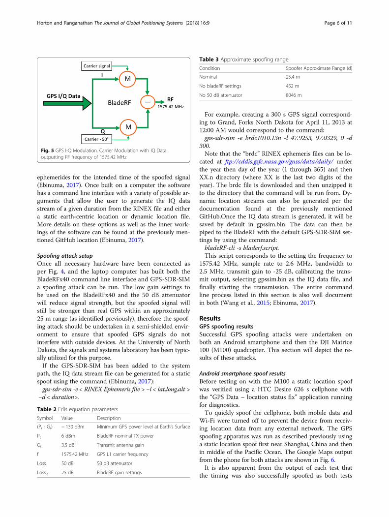
Basic spoofing hardwareThe hardware necessary to spoof the M100 include acomputer capable of generating the spoofed signal’s IQdata stream; a software defined radio (SDR) that willtransform the IQ data into RF output; an antenna thatoperates at 1575.42 MHz frequency used by the L1 GPSsignal; and an appropriately selected attenuator to en-sure that the spoofed signals do not travel beyond thetesting radius. The spoofing setup at the University ofNorth Dakota (UND) uses a low-cost Dell laptop withWindows 10 operating system connected to a Bla-deRFx40 SDR with a 50 dB attenuator connecting to aGarmin GPS antenna on one of its transmit SMA con-nectors. This hardware setup and the bladeRF I-Qmodulation is shown in Figs. 4 and 5 respectively.
Fig. 2 GUI Interface for Matrice 100. Real Time Control Test Environment that show GPS status and flight parameters
Horton and Ranganathan The Journal of Global Positioning Systems (2018) 16:9 Page 4 of 11

Spoofing hardware rangeAn approximate range of the GPS spoofing setup de-scribed can be calculated by combining the known pa-rameters of the GPS L1 signal power at the Earth’ssurface, carrier frequency, the transmit power of thebladeRF, and the losses due to the software settings andattenuator.
By manipulating the Friis Transmission Equation:
Pr ¼ Pt þ Gt þ Gr−FSPL−X
Loss ð1Þ
FSPL ¼ 20 log4πc
� �þ 20 log fð Þ þ 20 log dð Þ ð2Þ
d ¼ 10 − Pr−Grð ÞþPtþGt−20 log 4πcð Þ−20 log fð Þ−
PLossð Þ=20 ð3Þ
The values to be used in eq. 3 to calculate an esti-mated range of the GPS spoofing apparatus describedare shown in Table 2. Table 3 shows the results for thenominal range calculation as well as when either the at-tenuator or output power settings of the bladeRF are notproperly selected.The results of Table 3 demonstrate the importance of
the attenuator and bladeRF gain settings in ensure thatthe spoofing apparatus range is properly controlled.Note that loss parameter used in eq. 3 to derive the
approximate spoofing range did not account for the at-tenuation due to cables, atmosphere, or physical obsta-cles. As such the simple calculation utilized representan order-of-magnitude estimate for line of site range.
Basic spoofing softwareThe software used to generate the spoofed GPS signal’s IQdata stream that will be fed the BladeRFx40 SDR is theopen-source GPS-SDR-SIM created by Takuji Ebinumawhich can be found on GitHub at: https://github.com/osqzss/gps-sdr-sim (Ebinuma, 2017). The GPS-SDR-SIMsoftware can generate an IQ data stream for both static lo-cation and dynamic user-defined motion profiles. The IQdata is generated using a RINEX navigation file for GPS
Fig. 4 GPS Spoofing Apparatus. Test Bed Framework showing SDR and UAS integration
Fig. 3 Matrice 100 Specifications. Specifications indicating batteryinformation, flight and remote controller information
Horton and Ranganathan The Journal of Global Positioning Systems (2018) 16:9 Page 5 of 11
ephemerides for the intended time of the spoofed signal(Ebinuma, 2017). Once built on a computer the softwarehas a command line interface with a variety of possible ar-guments that allow the user to generate the IQ datastream of a given duration from the RINEX file and eithera static earth-centric location or dynamic location file.More details on these options as well as the inner work-ings of the software can be found at the previously men-tioned GitHub location (Ebinuma, 2017).
Spoofing attack setupOnce all necessary hardware have been connected asper Fig. 4, and the laptop computer has built both theBladeRFx40 command line interface and GPS-SDR-SIMa spoofing attack can be run. The low gain settings tobe used on the BladeRFx40 and the 50 dB attenuatorwill reduce signal strength, but the spoofed signal willstill be stronger than real GPS within an approximately25 m range (as identified previously), therefore the spoof-ing attack should be undertaken in a semi-shielded envir-onment to ensure that spoofed GPS signals do notinterfere with outside devices. At the University of NorthDakota, the signals and systems laboratory has been typic-ally utilized for this purpose.If the GPS-SDR-SIM has been added to the system
path, the IQ data stream file can be generated for a staticspoof using the command (Ebinuma, 2017):gps-sdr-sim -e < RINEX Ephemeris file > −l < lat,long,alt >
−d < duration>.
For example, creating a 300 s GPS signal correspond-ing to Grand, Forks North Dakota for April 11, 2013 at12:00 AM would correspond to the command:gps-sdr-sim -e brdc1010.13n -l 47.9253, 97.0329, 0 -d
300.Note that the “brdc” RINEX ephemeris files can be lo-
cated at ftp://cddis.gsfc.nasa.gov/gnss/data/daily/ underthe year then day of the year (1 through 365) and thenXX.n directory (where XX is the last two digits of theyear). The brdc file is downloaded and then unzipped itto the directory that the command will be run from. Dy-namic location streams can also be generated per thedocumentation found at the previously mentionedGitHub.Once the IQ data stream is generated, it will besaved by default in gpssim.bin. The data can then bepiped to the BladeRF with the default GPS-SDR-SIM set-tings by using the command:bladeRF-cli -s bladerf.script.This script corresponds to the setting the frequency to
1575.42 MHz, sample rate to 2.6 MHz, bandwidth to2.5 MHz, transmit gain to -25 dB, calibrating the trans-mit output, selecting gpssim.bin as the IQ data file, andfinally starting the transmission. The entire commandline process listed in this section is also well documentin both (Wang et al., 2015; Ebinuma, 2017).
ResultsGPS spoofing resultsSuccessful GPS spoofing attacks were undertaken onboth an Android smartphone and then the DJI Matrice100 (M100) quadcopter. This section will depict the re-sults of these attacks.
Android smartphone spoof resultsBefore testing on with the M100 a static location spoofwas verified using a HTC Desire 626 s cellphone withthe “GPS Data – location status fix” application runningfor diagnostics.To quickly spoof the cellphone, both mobile data and
Wi-Fi were turned off to prevent the device from receiv-ing location data from any external network. The GPSspoofing apparatus was run as described previously usinga static location spoof first near Shanghai, China and thenin middle of the Pacific Ocean. The Google Maps outputfrom the phone for both attacks are shown in Fig. 6.It is also apparent from the output of each test that
the timing was also successfully spoofed as both tests
Table 3 Approximate spoofing range
Condition Spoofer Approximate Range (d)
Nominal 25.4 m
No bladeRF settings 452 m
No 50 dB attenuator 8046 m
Table 2 Friis equation parameters
Symbol Value Description
(Pr - Gr) − 130 dBm Minimum GPS power level at Earth’s Surface
Pt 6 dBm BladeRF nominal TX power
Gt 3.5 dBi Transmit antenna gain
f 1575.42 MHz GPS L1 carrier frequency
Loss1 50 dB 50 dB attenuator
Loss2 25 dB BladeRF gain settings
Fig. 5 GPS I-Q Modulation. Carrier Modulation with IQ Dataoutputting RF frequency of 1575.42 MHz
Horton and Ranganathan The Journal of Global Positioning Systems (2018) 16:9 Page 6 of 11

were run in Grand Forks, ND at approximately 6 PM.Figure 7 show the output of the GPS Data application’ssatellite view compared to the satellite signals being gen-erated by the spoofing software shown in the commandline. The application clearly shows that satellites 7, 6, 7,13, 15, 20, 29, and 30 being used for the GPS lock withhigh signal strengths. It can also be seen that these areprecisely the satellites being spoofed by GPS-SDR-SIM.Note that satellite 12 is being spoofed, but not used bythe cellphone for gps lock.
DJI Matrice 100 resultsThe M100 was first subject to a static location spoof inthe same manner as the Android smartphone. TheM100 was spoofed much more quickly than the smart-phone most likely because of the strength of its GPSreceiver along with the fact that it uses GPS alone forpositioning rather than cellular networks and Wi-Fi. TheDJI Go application displayed the location of the M100 tobe in Australia precisely as configured in the spoofingsetup. Furthermore, the latitude and longitude data ob-tained via the Wi-Fi to UART interface with the OSDKand logged by the QT application showed that the M100was reporting its location at the same location inAustralia. Both the DJI Go application output and the
location transmitted over the OSDK interface pluggedinto Google Maps are depicted in Fig.8. After conduct-ing the static location spoof, a predefined dynamic loca-tion profile included as an example in the previouslymentioned GPS-SDR-SIM GitHub repository was fed tothe GPS-SDR-SIM software.The output of the DJI Go application location for this
test is shown in Fig. 9. Fusion sensor data was also col-lected using the DJI OSDK Wi-Fi interface. The DJI Ma-trice 100 was sitting idle on a test bench during theattack with its propellers removed to keep the dronefrom damaging itself. The DJI Go App reported thedrone moving in a large circular path and the Matrice100 motors were actuating at full power to counteractthe spoofed movement. If the drone would have beenhovering at this point it would surely have crashed attempt-ing its location against the falsified movement profile.
DiscussionGPS spoofing detection and defensesBasic sensor comparison spoofing detectionThe “fusion” sensor data, a preprocessed combination ofthe accelerometer and gyroscope data telemetered by theMatrice 100 that approximates the velocity along absolutethree-dimensional axes (DJI, 2017b), versus the apparent
Fig. 6 Cellphone GPS spoof tests. Fake locational and Actual positions
Horton and Ranganathan The Journal of Global Positioning Systems (2018) 16:9 Page 7 of 11

velocity calculated using the GPS data both obtained dur-ing the dynamic movement spoof are shown in Fig. 10. Asdescribed previously the Matrice 100 was sitting idle dur-ing this test which is confirmed by the output sensor data’scontrast to the GPS data.Although this data represents the extreme case of the
DJI drone have spoofed movement while no real move-ment exists, the data clearly shows the discrepancy be-tween the GPS data and the other sensors aboard theMatrice 100. It follows that a simple fact checking ofperipheral sensor data versus the GPS positioning couldbe used as a means of spoofing defense.The inherent noise of the sensors poses a significant
challenge to the implementation of a simple sensor fact
check for GPS spoofing. A Kalman filter using the accel-erometer and gyroscope data was implemented on thedata to reduce any sensor noise, but further testing withthis Kalman filter along with the introduction of add-itional sensors such as the cameras, or ultrasonic sensorscurrently implemented on the Matrice 100 to improvethe Kalman filter accuracy remains future work.
Sophisticated spoofing detection methods overviewSome detection methods for anti-spoofing, specificallywithin UAS applications, include:
i. Synthetic Array Spoofing Discrimination: Themovement of a single receiver antenna over time
Fig. 7 Cellphone GPS Statistics. Statistics showing GPS with SDR-SIM CLI output
Horton and Ranganathan The Journal of Global Positioning Systems (2018) 16:9 Page 8 of 11

Fig. 9 M100 dynamic location GPS spoofing. Perimeter Range
Fig. 8 M100 DJI Go App Location. OSDK locational output
Horton and Ranganathan The Journal of Global Positioning Systems (2018) 16:9 Page 9 of 11

can be used as a type of synthetic array for spoofingdetection by monitoring the correlation in thechanging amplitude and phase angle for the GPSsignals. For a spoofed GPS signal, the individualsatellite will exhibit strong correlation changeswith antenna movement, which will not occur fortrue GPS received from multiple separate satellitetransmitters. This method shows promise for acontinually moving UAV.
ii. Power Variation vs Receiver Movement: Thismethod of spoofing detection is similar to thesynthetic movement based array except that itinstead monitors only the change in powerassociated with movement of the receiver. Asthe receiver moves all signals originating from asingle spoofer transmitter will increase or diminishin power unlike a true GPS constellation. Thismethod requires accurate power monitoring of thevery low power GPS signals and relies on enoughUAV movement to effect power at a detectiblelevel.
iii. Consistency Check with Other Navigation andPosition Technologies: This method relies oncomparing other sensors and position estimateswith the GPS position. This is the primary focusof UAV GPS spoofing detection related workconducted at the University of North Dakotathus far due to the availability of gyroscopes,accelerometers and even cameras readilyavailable on most commercial UAVs.
A more comprehensive review of GPS spoofing detec-tion methods, including those listed here, has been con-ducted in (Jafarnia-Jahromi et al., 2012).
GPS spoofing defenseOnce a spoofed GPS signal has been detected, the nextsignificant challenge is to take some sort of correctiveaction whether it be a UAV relying on other means ofnavigation via sensor networks or a smartphone obtain-ing positioning via the cellular network. These methodsof defense remain a significant research opportunity anda point of future work for this research.
ConclusionA GPS spoofing apparatus has been developed at theUniversity of North Dakota (UND) to implement spoof-ing attacks for the use of further development of detec-tion and defensive mechanisms. The steps undertaken toimplement this apparatus were detailed as well as themodifications to the Matrice 100 quadcopter necessaryfor effective spoofing attack data collection. The resultsof the spoofer in action have been presented along witha showcase of some of the data available from the Ma-trice 100 during operation.
AcknowledgementsThis research work is sponsored by Rockwell Collins Corporation, Cedar Rapids,IA, and authors appreciate the support and effort from the company, andspecifically Roger French, Principal Engineer at Rockwell Collins.
FundingRockwell Collins Corporation, AWARD Number UND22526.
Data statementData sharing not applicable to this article as no datasets were generated oranalyzed during the current study. If you do not wish to publicly share yourdata, please write: “Please contact author for data requests.”
Authors’ contributionsEH carried out the Kalman filter design, developed coding on GPS spoofing,and implementation. PR developed the software defined radio basedconfiguration, and conceived of the study, and participated in its design and
Fig. 10 Calculated Velocites.tif. Calculated Velocites
Horton and Ranganathan The Journal of Global Positioning Systems (2018) 16:9 Page 10 of 11
coordination and helped to draft the manuscript. Both authors read andapproved the final manuscript.
Competing interestsThe authors declare that they have no competing interests.
Publisher’s NoteSpringer Nature remains neutral with regard to jurisdictional claims inpublished maps and institutional affiliations.
Received: 22 November 2017 Accepted: 13 June 2018
ReferencesArafin M.T., Anand D. and Qu G., “A Low-Cost GPS Spoofing Detector Design for
Internet of Things (IoT) Applications”, 2017, pp. 161–166DJI, "DJI Developer Website.” 2017a. Internet: https://www.dji.com/DJI, "dji-sdk/Onboard-SDK (GitHub repository)." Internet: https://github.com/dji-
sdk/Onboard-SDK, 2017bEbinuma T., "GPS-SDR-SIM (GitHub repository).” Internet: https://github.com/
osqzss/gps-sdr-sim, 2017Fan X, Du L, Duan D (2017) Synchrophasor data correction under GPS spoofing
attack: a state estimation based approach. IEEE Transactions on Smart Grid,vol PP:1–1
Huang L. and Yang Q., "GPS spoofing low-cost GPS simulator," 2015Jafarnia-Jahromi A, Broumandan A, Nielsen J, Lachapelle G (2012) GPS
vulnerability to spoofing threats and a review of Antispoofing techniques. IntJ Navigation and Observation 2012(127072):16. https://doi.org/10.1155/2012/127072
JeeLabs, "esp-link (GitHub repository)." Internet: https://github.com/jeelabs/esp-link, 2017
Jiang X, Zhang J, Harding BJ, Makela JJ, Dominguez-Garcia AD (2013) SpoofingGPS receiver clock offset of Phasor measurement units. IEEE Trans Power Syst28:3253–3262
Karit D., "Using GPS spoofing to control time," 2017Li H. and Wang X., Detection of GPS spoofing through signal multipath signature
analysis, pp 1–5, 2016Shepard DP, Humphreys TE, Fansler AA (2012) Evaluation of the vulnerability of
phasor measurement units to GPS spoofing attacks. Int J Crit InfrastructureProt, vol 5 12(/01):146–153
Tippenhauer N.O., Popper C., Rasmussen K. and Capkun S., On the requirementsfor successful GPS spoofing attacks, 2011, pp. 75–86
Wang K., Chen S. and Pan A., "Time and position spoofing with open sourceprojects," 2015
Wang Y. and Chakrabortty A., Distributed monitoring of wide-area oscillations inthe presence of GPS spoofing attacks, pp. 1–5, 2016
Zou Q, Huang S, Lin F, Cong M (2016) Detection of GPS spoofing based on UAVmodel estimation. pp.:6097–6102
Horton and Ranganathan The Journal of Global Positioning Systems (2018) 16:9 Page 11 of 11