Development of a Dynamically Scaled General Transport Model
16
Development of a Dynamically Scaled Generic Transport Model Testbed for Flight Research Experiments Thomas Jordan, William Langford, Christine Belcastro, John Foster, Gautam Shah, Gregory Howland*, Reggie Kidd** NASA Langley Research Center Ph 757-864-4713 Fax 757-864-7607 [email protected] www.larc.nasa.gov *Lockheed Martin **Swales Aerospace Abstract: This paper details the design and development of the Airborne Subscale Transport Aircraft Research (AirSTAR) test-bed at NASA Langley Research Center (LaRC). The aircraft is a 5.5% dynamically scaled, remotely piloted, twin-turbine, swept wing, Generic Transport Model (GTM) which will be used to provide an experimental flight test capability for research experiments pertaining to dynamics modeling and control beyond the normal flight envelope. The unique design challenges arising from the dimensional, weight, dynamic (inertial), and actuator scaling requirements necessitated by the research community are described along with the specific telemetry and control issues associated with a remotely piloted subscale research aircraft. Development of the necessary operational infrastructure, including operational and safety procedures, test site identification, and research pilots is also discussed. The GTM is a unique vehicle that provides significant research capacity due to its scaling, data gathering, and control characteristics. By combining data from this testbed with full-scale flight and accident data, wind tunnel data, and simulation results, NASA will advance and validate control upset prevention and recovery technologies for
Transcript of Development of a Dynamically Scaled General Transport Model

Development of a Dynamically Scaled Generic Transport Model Testbed for Flight Research Experiments
Thomas Jordan, William Langford, Christine Belcastro, John Foster, Gautam Shah, Gregory Howland*, Reggie Kidd**
NASA Langley Research Center Ph 757-864-4713 Fax 757-864-7607
[email protected] www.larc.nasa.gov *Lockheed Martin
**Swales Aerospace
Abstract:
This paper details the design and development of the Airborne Subscale Transport
Aircraft Research (AirSTAR) test-bed at NASA Langley Research Center (LaRC). The
aircraft is a 5.5% dynamically scaled, remotely piloted, twin-turbine, swept wing,
Generic Transport Model (GTM) which will be used to provide an experimental flight test
capability for research experiments pertaining to dynamics modeling and control beyond
the normal flight envelope. The unique design challenges arising from the dimensional,
weight, dynamic (inertial), and actuator scaling requirements necessitated by the
research community are described along with the specific telemetry and control issues
associated with a remotely piloted subscale research aircraft. Development of the
necessary operational infrastructure, including operational and safety procedures, test
site identification, and research pilots is also discussed.
The GTM is a unique vehicle that provides significant research capacity due to its
scaling, data gathering, and control characteristics. By combining data from this testbed
with full-scale flight and accident data, wind tunnel data, and simulation results, NASA
will advance and validate control upset prevention and recovery technologies for

transport aircraft, thereby reducing vehicle loss-of-control accidents resulting from
adverse and upset conditions.
1.0 Introduction
The NASA Aviation Safety and Security Program (AvSSP) was established to develop
technologies for improved safety and security of commercial transport aircraft. The
Single Aircraft Accident Prevention (SAAP) Project of the AvSSP focuses on the
development of technologies to reduce aircraft accidents resulting from loss of vehicle
control (or upset) as well as failures. According to the National Transportation Safety
Board's accident database, 40% of all commercial aviation fatalities from 1990 – 1996
were due to loss of control. Control Upset Prevention & Recovery (CUPR) technologies
being developed under SAAP provide control under adverse flight conditions in order to
accommodate failures, prevent loss of control, and recover control during loss-of-control
events. Technologies being developed include enhanced models of vehicle dynamics
to characterize upset conditions, failure detection and identification (FDI) algorithms,
and adaptive guidance and control (G&C) laws. The upset dynamics models have been
developed for integration into an enhanced aircraft simulation that is being created for
improved upset recovery training, and to support the development and evaluation of the
FDI and G&C algorithms. These algorithms are being developed for use onboard
transport aircraft for improved situational awareness and control under adverse and
upset conditions related to loss-of-control events. Validation of these technologies is
therefore critical.
The AirSTAR testbed is being developed to provide an in-flight validation capability for
high risk flight testing of these AvSSP technologies. To accomplish this, researchers at
2

LaRC have undertaken the task of designing, fabricating, and operating a turbine
powered, dynamically scaled transport aircraft. While the challenge to design and
fabricate this research vehicle was significant, a more encompassing task of building
and training an infrastructure to operate the aircraft in a continuing safe and efficient
manner also began to evolve. This task included the education and training of a core
group of pilots, the development of safety and operational procedures and checklists,
the training of essential ground support personnel, and the identification and
coordination of test sites external to NASA Langley.
The rest of the paper is organized as follows: Section 2 describes the research
requirements for the AirSTAR testbed (including motivation and research goals);
Section 3 describes the risk mitigation effort undertaken in establishing the testbed
(including the development of a pilot training program, the establishment of a phased
aircraft development plan, and the development of a transport model simulation);
Section 4 describes the transport model development (including dynamic scaling
requirements, control and telemetry requirements, the model aircraft design, fabrication,
and testing); Section 5 describes support activities in the development (including safety
procedures and test site identification); and Section 6 provides some concluding
remarks. The development of ground facilities for this testbed will be presented in a
subsequent paper.
2.0 Research Requirements
2.1 Motivation
An integrated validation process is being developed under SAAP in parallel to the
technology development to provide advanced methods for analysis, simulation, and
3

experimental testing under adverse and upset conditions. Experimental testing will
involve both ground and in-flight testing. In-flight testing under adverse and upset
conditions poses a special challenge due to the high risk of the required flight
maneuvers. Figure 1 shows a depiction of a loss-of-control accident as it relates to
angles of attack and sideslip angle. High-risk operation at extreme flight conditions
outside of normal operation precludes the use of full-scale manned aircraft testing. The
AirSTAR subscale flight test capability is therefore being developed to address these
high-risk conditions.
0
10º
20º
30º
40º
50º
-40º -30º -20º -10º 0º 10º 20º 30º 40º0
10º
20º
30º
40º
50º
-40º -30º -20º -10º 0º 10º 20º 30º 40º0
10º
20º
30º
40º
50º
0
10º
20º
30º
40º
50º
-40º -30º -20º -10º 0º 10º 20º 30º 40º-40º -30º -20º -10º 0º 10º 20º 30º 40º
Angle of sideslip - deg
Ang
le o
f atta
ck -
deg
Loss-Of-Control Accident data
Normal Flt envelopeCurrent
wind tunnel data envelope
Extrapolated data envelope
Figure 1. Plot showing a transport loss-of-control accident relative to angle-of-attack and sideslip
2.2 Research Goals
The goal of the AirSTAR testbed is to provide an in-flight research environment for the
evaluation and validation of safety-critical technologies, including the flight validation of:
vehicle dynamics modeling and simulation technologies for upset characterization,
4

failure detection and accommodation system technologies, and upset recovery system
technologies.
3.0 Risk Mitigation
3.1 Pilot Training Program
After examining the risk associated with flying a subscale research vehicle, it became
obvious that pilot proficiency plays a major role in the successful operation of the
vehicle. According to a survey conducted by the Jet Pilots Organization (1) at model jet
events during 2003, over 50% of the known causes of turbine vehicle crashes were due
to pilot error. In order to assure a long life and to be able to operate the research
vehicle in various upset conditions, a capable and practiced group of subscale turbine
pilots is required. To this end, a pilot training program was developed to grow the
necessary skills. This program has two main thrusts, one being the field operation of
increasingly more complex subscale air vehicles, and the other being the development
and use of a GTM simulator.
3.2 Phased Model Aircraft Approach
An array of airplanes was utilized in the pilot training program as shown in Figure 2.
Phases 1 and 2 of the program make extensive use of commercial-off-the-shelf (COTS)
aircraft in an effort to control cost and maximize flight time. In order to assess the initial
skill level of the Langley pilots, the training program started off with a propeller driven,
aerodynamically stable model. Training then progressed in Phase 1 to faster and more
agile propeller and ducted fan powered aircraft.
Phase 2 of the program began with the introduction of turbine powered aircraft. As a
guideline for the turbine portion of the training program, the rules and regulations of the
5
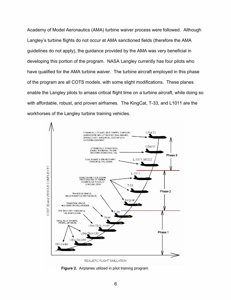
Academy of Model Aeronautics (AMA) turbine waiver process were followed. Although
Langley’s turbine flights do not occur at AMA sanctioned fields (therefore the AMA
guidelines do not apply), the guidance provided by the AMA was very beneficial in
developing this portion of the program. NASA Langley currently has four pilots who
have qualified for the AMA turbine waiver. The turbine aircraft employed in this phase
of the program are all COTS models, with some slight modifications. These planes
enable the Langley pilots to amass critical flight time on a turbine aircraft, while doing so
with affordable, robust, and proven airframes. The KingCat, T-33, and L1011 are the
workhorses of the Langley turbine training vehicles.
Figure 2. Airplanes utilized in pilot training program
6

Phase 3 of the training program is comprised of twin turbine, swept wing, transport
aircraft which have been either highly modified or entirely designed and fabricated by
Langley personnel. The L1011 Mod2 aircraft was modified in-house for dual turbine
and spin recovery operation. The T1 and T2 aircraft were designed and fabricated in-
house as dynamically scaled 5.5% models of a twin-engine transport aircraft. The T1
serves primarily as a trainer, but also is used for various subsystem checkout and
validation. With the T2 airplane, the main research aircraft, weight has been taken out
of the airframe through the use of advanced composite materials in place of fiberglass,
which allows for a greater payload of research instrumentation.
3.3 GTM Simulator
As another component of the risk mitigation scheme, a real-time piloted simulation of
the GTM was developed to support pilot training and to provide a tool for evaluating the
handling characteristics of the flight vehicle. The simulation was based on a non-linear,
six degree-of-freedom model that included aerodynamic, thrust, control system,
geometry, and mass properties. The aerodynamic model was based on an extensive
series of wind tunnel tests conducted at NASA LaRC, using a model with moldlines
identical to the GTM. During these tests, over 46,000 data points were obtained to
model the effects of angle of attack, angle of sideslip, control deflections, angular rates,
and component effects. These data points were used to develop a non-linear
mathematical representation of the aerodynamic properties for angles of attack ranging
from –10 to +80 degrees and angles of sideslip from –45 to +45 degrees. The dynamic
model was hosted on a desktop PC and was interfaced with a typical RC pilot control
box utilizing a high-resolution visual display.
7

An important benefit of the simulator is that it provides a tool for the pilots to learn the
basic handling qualities of the model as well as practice flight procedures during
degraded performance conditions. For example, the simulator allows the pilots to
practice recovery from engine failure during critical flight conditions such as takeoff or
landing. In addition, the simulator is invaluable for flight planning by providing estimates
of structural loads during test maneuvers.
4.0 Model Development – GTM T2
4.1 Dynamic Scaling Requirements
In order for the model to appropriately represent the flight characteristics of a full scale
airplane, specific dynamic scaling requirements are imposed on the subscale aircraft.
Among these are dimensional, weight, inertial, and actuator response scaling issues.
Table 1 lists some of the full scale aircraft properties and the requisite model properties.
Table 1 – Selected scaled parameters of a 5.5% model
Length Wingspan Weight Roll inertia Airspeed Altitude Full Scale Transport 145.5 ft 124 ft 200,000
lbs 2.64e6 sl-
ft2 320 mph 13000 ft
5.5% Model 96 in 82 in 49.6 lbs 1.33 sl-ft2 75 mph 1000 ft
In general, assuming a scale factor of K, then dimensional scaling is proportional to K1,
area scaling to K2, weight and volume scaling to K3, mass moments of inertias to K5 and
response to K . For example:
1
1
Model wingspan = Full scale wingspan * = 145.5 ft *0.055 = 8 ft
K
What this means to the model designer is that while size and weight go down for a
subscale design, response time (such as for actuation systems) gets faster.
8
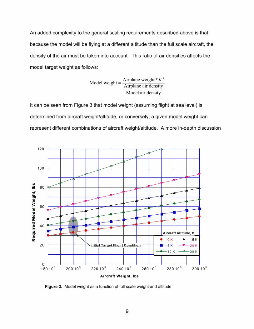
An added complexity to the general scaling requirements described above is that
because the model will be flying at a different altitude than the full scale aircraft, the
density of the air must be taken into account. This ratio of air densities affects the
model target weight as follows:
3Airplane weight *Model weight Airplane air densityModel air density
K=
It can be seen from Figure 3 that model weight (assuming flight at sea level) is
determined from aircraft weight/altitude, or conversely, a given model weight can
represent different combinations of aircraft weight/altitude. A more in-depth discussion
0
20
40
60
80
100
120
180 10 3 200 10 3 220 10 3 240 10 3 260 10 3 280 10 3 300 10 3
0 K
5 K
10 K
15 K
20 K
30 K
Aircraft Weight, lbs
Aircraft Altitude, ft
In itial Target Fl igh t Cond ition
e
Figure 3. Model weight as a function of full scale weight and altitud
9
of similitude and scaling requirements can be found in NASA publications by Gainer and
offman (2) and Wolowicz et al. (3).
n initial scaling factor of 5.5% was chosen based on the fact that Langley had
reviously fabricated and extensively tested in it’s wind tunnels a model of that scale.
he aerodynamic data from those wind tunnel tests would be used to develop the
imulator described above. Also, the original fabrication molds were still in existence
hich provided a time and cost savings in fabrication of the model. A feasibility study
as conducted to determine if the dynamic scaling requirements of a 5.5% model could
e met given the control, data, operational, and telemetry requirements. The results of
e study showed that the research instrumentation and 5.5% dynamic scaling
quirements could co-exist in an aircraft of that size. Other requirements such as
gidity, symmetry, flight time, CG location, take-off and landing speeds, propulsion,
irements
nging
nd
rch
H
A
p
T
s
w
w
b
th
re
ri
video, and control surface deflection were addressed in the design.
4.2 Control and Telemetry Requ
The unique research requirements of the AirSTAR testbed dictate several challe
control and telemetry solutions. Specific downlink data requirements include the
following: potentiometers at all control surface hinge points for precise position
feedback; GPS, attitude, heading, airspeed and acceleration data for aircraft positions
and rates; video from an onboard camera; and various status parameters such as
commanded control surface position, throttle position, and battery voltage. In total
there are over 60 channels of data that are transmitted from the airplane at rates
ranging from 27 Hz up to 216 Hz. Once this data stream is received in the grou
station, a real-time control system merges these inputs with the inputs from a resea
10

pilot and, using the researcher supplied control algorithms, computes new control
surface commands to send to the airplane. L-band and S-band transmitters and
loop control system must operate
ent of
ch
with
e
lies.
nd inertias can be estimated.
receivers are utilized for these links. This closed
reliably at 200 Hz. Operational requirements dictate that the test volume of the aircraft
should be approximately 2 miles x 1 mile and 1 mile high. Details of the developm
the ground station and its capabilities will be presented in a forthcoming paper.
An additional telemetry uplink to the aircraft is used for the safety pilot, who utilizes a
COTS R/C transmitter and receiver operating at 72 MHz. A remotely actuated swit
directed by the safety pilot dictates whether control of the airplane comes from the
research pilot or the safety pilot.
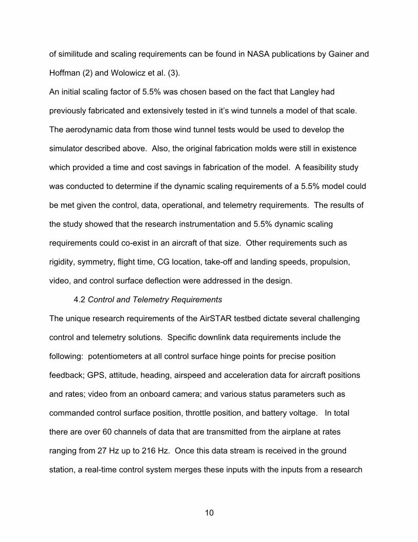
4.3 Design
Since the size, weight, and inertias of the vehicle are all dictated in the research
requirements, the challenge is to design the airframe and all of its associated
substructure and assemblies to meet the target values. The vehicle design starts
the creation of Pro-Engineer Solid Model parts that represent the conceptual vehicle
with its individual parts and components. All of the vehicle’s components are modeled
as accurately as possible with regard to size and weight. Commercial-off-the-shelf parts
are measured, weighed, and then replicated using the Pro-Engineer Solid Model
software. Sub-assemblies are then created from these individual parts to represent th
landing gear, fuselage, and wing assemblies, the pneumatic system, etc. A final
assembly, shown in Figure 4, is then created from combining all of the sub-assemb
From this final assembly, weights a
11
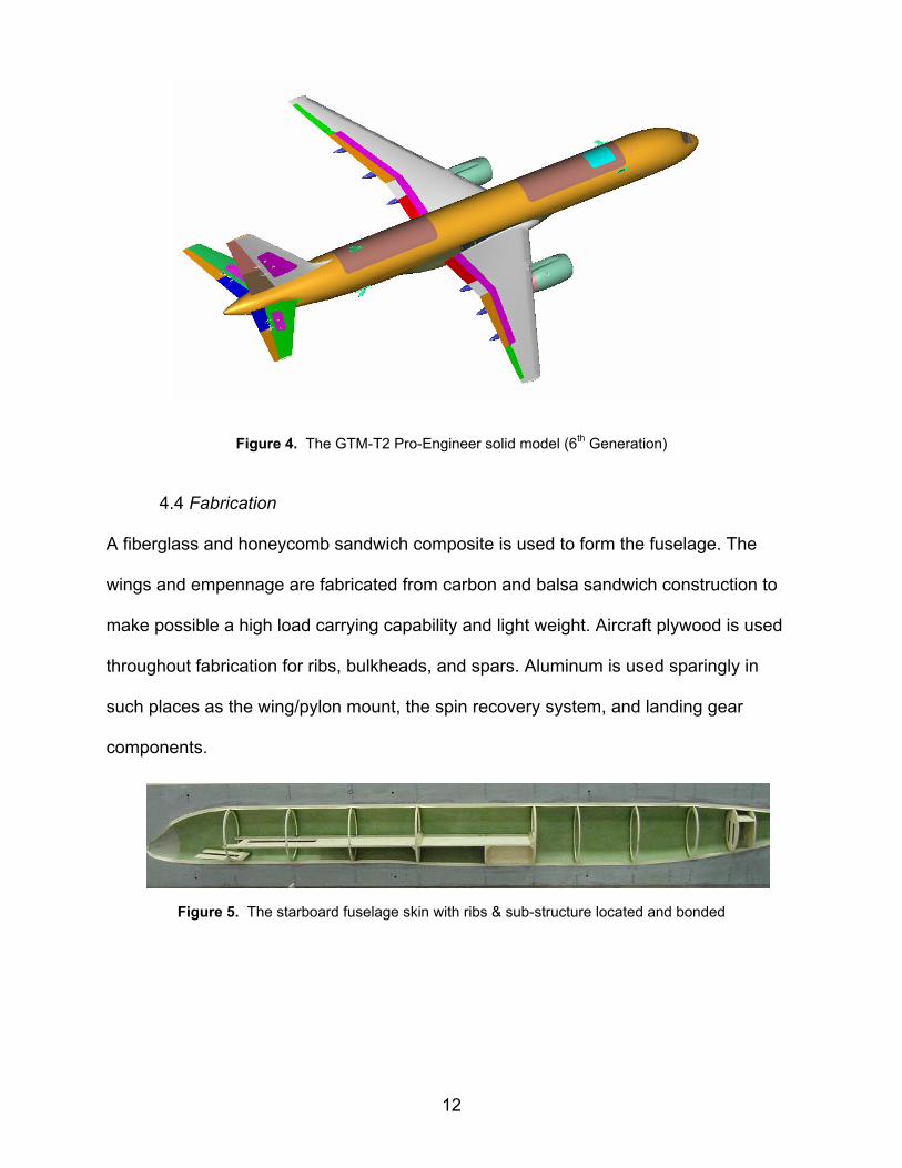
4.4 Fabrication
A fiberglass and honeycomb sandwich composite is used to form the fuselage. The
wings and empennage are fabricated from carbon and balsa sandwich construction to
make possible a high load carrying capability and light weight. Aircraft plywood is
throughout fabrication for ribs, bulkheads, and spars. Aluminum is used sparingly in
such places as the wing/pylon mount, the spin recovery system, and landing gear
components.
Figure 4. The GTM-T2 Pro-Engineer solid model (6th Generation)
used
Figure 5. The starboard fuselage skin with ribs & sub-structure located and bonded
12

4.5 Testing
The ground testing for the vehicle consists of three phases: the aerodynamic load
testing, the inertial testing, and the taxi testing. The aerodynamic load testing is done
bags distributed in an elliptical shape over the wings. The inertial testing
is done in the pitch, yaw, and roll orientations using a bi-filar pendulum. Inertial testing
with lead shot
of the T1 aircraft yielded results which were within 2% of the estimated Pro-Engineer
values. The taxi testing (low and high speed) is used to establish ground handling and
braking characteristics and for overall system checkout before the first flight.
Figure 6. Foreground: the 5.5% GTM undergoing “yaw” inertial testing on a bi-filar pendulum. Background: the 5.5% GTM air damping corrections model (paper construction)
5.0 Su pment
pport Develo
5.1 Safety procedures
Safety has always occupied a position of great importance in NASA research and
development programs. One of the early goals of the AirSTAR program was to
determine all hazards and associated risks involved with this project. While the flying of
Remotely Piloted Vehicles (RPV) is not new, intentionally placing a dynamically scaled
13

aircraft in conditions known to have caused the full scale aircraft to crash, for the
purpose of trying to recover from this condition, is new and exciting research. A formal
analysis was completed to identify potential hazards and their consequences and to
develop the proper response. Mitigation of risk to minimal levels and the development
and practice of proper responses when things go wrong are fundamental to the
AirSTAR safety program. The safety of the public and NASA personnel always takes
precedence over testing and research.
Checklists, inspection lists, logbooks, and procedures covering all areas of operation
were created to expose and prevent many potential problems. Some examples of these
21 documents are pre-flight inspection, post-flight inspection, battery charging, flying
intenance.
The pilot training program, as discussed earlier, plays a large role in the development of
overall project safety. Not only does it mature pilot skills to the appropriate level, but it
also helps develop safe handling and operating procedures for the AirSTAR team. The
training program is where checklists and procedures are field tested on standard aircraft
with less potential risk.
Individual components were tested and analyzed in an effort to reduce the
consequences of failure. Electronic components were evaluated in such areas as loss
of signal, loss of power, and loss of electrical ground to develop failure modes and
responses. Efforts have been made to eliminate single point failures that would result in
the loss of the vehicle. Appropriate flight termination mechanisms and procedures were
incorporated for emergencies, to minimize potential damage to the environment,
surroundings, and personnel.
site inspection, starting procedures, emergency procedures, and ma
14

5.2 Test site identification
When considering a potential test site for the AirStar testbed, two main factors are
e also
search
ce
tbed consists of a unique ground station and remotely
piloted flight research experiments related to
considered: does the site maximize the likelihood of a successful flight; and does the
site provide adequate isolation so that if there is an incident, damage to surrounding
personnel and property is minimized? Since the AirSTAR is a testbed with plans to
operate on a frequent basis, travel and the associated cost for the operations ar
taken into consideration. Most of the turbine training flights have taken place at
Aberdeen Field in Smithfield, VA. This is a private airfield with a 60’ x 6000’ runway. It
is located within 45 minutes of NASA LaRC and is utilized two to three times per week
by the pilots. The field provides a very good environment for training flights of the low
risk turbine models.
However, because of the increased operations area and the nature of the re
maneuvers and the associated risk, flights of the T2 airplane require a larger and more
isolated test area. For this reason, research flights of the T2 will most likely take pla
at a controlled access government facility. To date, the project has identified Wallops
Flight Facility on the Eastern Shore of VA as a potential test area.
6.0 Conclusions
The NASA Langley AirSTAR tes
aircraft which will be utilized to conduct
control upset prevention and recovery of air transport vehicles. Integrating this data
with data from wind tunnels and full scale flight experiments will enable the creation of
more realistic flight simulators for pilot training and the development of safer and more
15

robust transport aircraft of the future, all with the goal of reducing loss of control aircraft
accidents.
Acknowledgment
The authors would like to thank Andrea Muraco and Mariusz Wisniewski for their
assistance.
References
http://www.gajets.net/2003_RMI_Survey/RMI_2003_Survey_Results.html1. Jet Pilots Organization,
Equations of Motion Used in Free-Flight and Wind Tunnel Data Reduction and
Scaling Relationships as Applied to Model Testing, NASA TP
2. T.G. Gainer and S. Hoffman, Summary of Transformation Equations and
Analysis, NASA SP-3070, 1972
3. C.H. Wolowicz, J.S. Bowman, Jr., and W.P. Gilbert, Similitude Requirements and -1435, 1979
16