Development of a beam-column joint model for use in the ... Bradley.pdf · the CTV Building...
12
Development of a beam-column joint model for use in the CTV Building earthquake response analysis 2016 NZSEE Conference D.S. Bradley, N.J. Brooke, T.J. Stuart, B.J. Davidson Compusoft Engineering Limited, Newmarket, Auckland. ABSTRACT: The CTV Building in Christchurch collapsed during the 6.3 magnitude earthquake that occurred on 22 February 2011. The collapse resulted in the loss of 115 lives. Compusoft Engineering Limited was engaged by the CERC to develop a forensic analysis model of the building to assist in determining the cause of the collapse. This paper describes the work associated with developing a beam-column joint behaviour model for implementation in the analysis model. Specific attention is paid to the challenges of modelling non-linear joint behaviour, particularly for joints with such unusual features as circular columns and deficient anchorage of beam reinforcement. The behaviour model developed produced plausible analysis results. 1 INTRODUCTION It is common knowledge that the CTV Building collapsed catastrophically during the February 2011 “Lyttelton” earthquake, resulting in the loss of 115 lives. Consequently, the collapse was considered at length by the Canterbury Earthquake Royal Commission (CERC), with the possible causes of collapse being a particular focus of the investigations. Compusoft Engineering (CEL) was engaged by the CERC to assist in the determination of the cause of the collapse through the development of a forensic analysis model of the building. This model was used to undertake non-linear time history analyses based on earthquake records from nearby recording stations. The analysis model was developed using SAP2000 (CSI Berkeley 2011). Development of the non- linear model relied on both CEL‟s expertise and also the collaboration of other members of the “Expert Panel for Nonlinear Time History Analysis” appointed by the CERC. Development of the model was complicated by the inadequate design of the building and consequent need to model non- linear behaviour not expected to occur in „modern 1 ‟ buildings and the uncertain cause of collapse, which made it essential that the probable behaviour of many possible causes of collapse be carefully considered. The complexity of the non-linear behaviour of the building, and in particular the beam column joint behaviour is the focus of this paper. However, prior to addressing this topic, a brief description of the building is provided to contextualise the discussion. 2 BUILDING DESCRIPTION The CTV building was a 6 storey structure of reinforced concrete construction with plan dimensions of approximately 31 m by 23 m. An overall impression of the structural model is shown in Figure 1. Construction consisted of in-situ composite concrete Hi-Bond floors supported by (partially precast) concrete frames. The frames were not intended to contribute to lateral force resistance, which was principally provided by reinforced concrete walls; a complex of walls that also provided support to a 1 In this paper the onset of the “modern” era of structural engineering in New Zealand is considered to coincide with the broad adoption of capacity design principals, i.e. since the introduction of NZS 4203:1976 and NZS 3101:1982.
Transcript of Development of a beam-column joint model for use in the ... Bradley.pdf · the CTV Building...
Development of a beam-column joint model for use in
the CTV Building earthquake response analysis
2016 NZSEE Conference
D.S. Bradley, N.J. Brooke, T.J. Stuart, B.J. Davidson
Compusoft Engineering Limited, Newmarket, Auckland.
ABSTRACT: The CTV Building in Christchurch collapsed during the 6.3 magnitude
earthquake that occurred on 22 February 2011. The collapse resulted in the loss of 115
lives. Compusoft Engineering Limited was engaged by the CERC to develop a forensic
analysis model of the building to assist in determining the cause of the collapse. This
paper describes the work associated with developing a beam-column joint behaviour
model for implementation in the analysis model. Specific attention is paid to the
challenges of modelling non-linear joint behaviour, particularly for joints with such
unusual features as circular columns and deficient anchorage of beam reinforcement. The
behaviour model developed produced plausible analysis results.
1 INTRODUCTION
It is common knowledge that the CTV Building collapsed catastrophically during the February 2011
“Lyttelton” earthquake, resulting in the loss of 115 lives. Consequently, the collapse was considered
at length by the Canterbury Earthquake Royal Commission (CERC), with the possible causes of
collapse being a particular focus of the investigations. Compusoft Engineering (CEL) was engaged
by the CERC to assist in the determination of the cause of the collapse through the development of a
forensic analysis model of the building. This model was used to undertake non-linear time history
analyses based on earthquake records from nearby recording stations.
The analysis model was developed using SAP2000 (CSI Berkeley 2011). Development of the non-
linear model relied on both CEL‟s expertise and also the collaboration of other members of the
“Expert Panel for Nonlinear Time History Analysis” appointed by the CERC. Development of the
model was complicated by the inadequate design of the building and consequent need to model non-
linear behaviour not expected to occur in „modern1‟ buildings and the uncertain cause of collapse,
which made it essential that the probable behaviour of many possible causes of collapse be carefully
considered.
The complexity of the non-linear behaviour of the building, and in particular the beam column joint
behaviour is the focus of this paper. However, prior to addressing this topic, a brief description of the
building is provided to contextualise the discussion.
2 BUILDING DESCRIPTION
The CTV building was a 6 storey structure of reinforced concrete construction with plan dimensions
of approximately 31 m by 23 m. An overall impression of the structural model is shown in Figure 1.
Construction consisted of in-situ composite concrete Hi-Bond floors supported by (partially precast)
concrete frames. The frames were not intended to contribute to lateral force resistance, which was
principally provided by reinforced concrete walls; a complex of walls that also provided support to a
1 In this paper the onset of the “modern” era of structural engineering in New Zealand is considered to coincide
with the broad adoption of capacity design principals, i.e. since the introduction of NZS 4203:1976 and
NZS 3101:1982.

stair and lift core were located at the north of the building (external to the main floor plate), and a
reinforced concrete coupled shear wall was situated on the south face of the building. The building
was supported by shallow reinforced concrete foundations, comprising pads supporting the internal
columns and inverted 'tee' beams supporting the perimeter columns and walls.
Figure 1 - Views of the CTV Building structural model viewed from south-east (left) and from the east with floor slabs omitted (right)
3 NONLINEAR BEHAVIOUR CONSIDERED IN THE CTV BUILDING ANALYSIS
The CTV building was designed as a ductile building and as a consequence it was expected to exhibit
non-linear behaviour during a moderate to large earthquake event. By design this non-linearity should
have resulted from formation of plastic hinges in the walls, coupling beams, and frames. If such
elements are correctly detailed in accordance with Standards their behaviour is well understood and
easily modelled. In contrast, observed behaviour and review of drawings indicated that many other
sources of non-linearity significantly affected the behaviour of the CTV building and would thus
require inclusion in the forensic model. Specifically, the non-linearities modelled were:
Nonlinear column hinging, including axial interaction effects;
Beam flexural hinging;
Beam-column joint flexibility and strength degradation;
Strength and stiffness of diaphragm connections to north core shear walls, including
gapping behaviour;
Non-linear behaviour of diagonally reinforced coupled shear walls.
Gapping (lift off) of foundation elements from supporting soils.
Non-linear flexural behaviour of shear walls.
Non-linear behaviour of specific parts of the diaphragms.
Discussion of the reasons for and manner of all of the above non-linearities is beyond the scope of a
conference paper, as is the resulting modelled response of the building as a whole. Instead, this paper
focuses on the particular challenges associated with modelling of the beam-column joints of the CTV
Building. Details of other aspects of the model and the analysis results can be found in various
reports prepared for or by the CERC (Compusoft Engineering Limited 2012; Cooper et al. 2012).
4 MODELLING OF BEAM-COLUMN JOINT BEHAVIOUR
Beam-column joints in typical modern reinforced concrete structures are designed to ensure that they
are stronger than the beam and column members framing into the joint. Such joints can reasonably be
assumed to respond elastically during an earthquake with any inelastic behaviour occurring in the
adjacent elements, and thus it is not necessary to specifically model the beam-column joint beyond
accounting for the occurrence of elastic deformation in the joint core.

In contrast, the beam-column joints of the CTV Building were significantly deficient in relation to
modern design procedures. Preliminary analysis indicated that many joints would experience
demands in excess of their strength. Thus it was established that non-linear behaviour of the beam-
column joint core required explicit consideration in the analysis model.
During development of the CTV Building analysis model there was debate as to whether the column
transverse reinforcement extended through the joint core. However, calculations indicated the
behaviour of the joints would be akin to unreinforced joints even if the sparse column transverse
reinforcement did extend into them. The behaviour of such joints is still a highly active research
topic, with significant uncertainty regarding their mechanics and behaviour. Thus in any scenario,
realistic non-linear modelling of such joints is non-trivial exercise; the joints of the CTV building
were particularly challenging to assess due to their featuring circular columns, “weak column-strong
beam” behaviour, biaxial loading, and deficient hooked reinforcement anchorages, none of which are
well considered in the literature. Consequentially, no „off-the-shelf‟ model for the behaviour of the
joints was immediately apparent; instead a specific model was developed based on extensive review
of the literature. This model is described in the following sections.
4.1 Adopted Analysis Model
A number of methods could have been used to incorporate beam-column joint response within a
structural finite element model. Broadly, the methods available either used a single finite element
calibrated to match the overall behaviour of the joint core or multiple finite elements with different
elements accounting for various aspects (e.g. bond slip, the diagonal struts etc.) that contribute to the
joint behaviour.
Joint shear stresses develop as a result of the action of shear and flexural forces from the adjacent
beams and columns on the joint core. The advantages of a multi-element model of the joint core (e.g.
Figure 2) are principally that it allows realistic representation of the entry of these forces into the joint
core, and additionally allows individual calibration of various load paths through the joint against
experimental observations.
Figure 2 - Example of beam-column joint finite element model relying on inputs from multiple nodes (from Mitra and Lowes 2007)
Consideration was given to implementing a model of the type shown in Figure 2, but the concept was
ultimately not pursued for a number of reasons:
1. It was not certain that the additional complexity would result in a more reliable or
accurate representation of the joint behaviour due to the overall uncertainties about
the behaviour of the joints; and
2. Extension of the model shown to accommodate three-dimensional joints was not
reported in literature reviewed by CEL.
3. Implementation of such a multi-element model would have significantly enhanced
both the computational demands and also the amount of post-processing required;

Instead, the method adopted for the CTV Building structural model was to develop a non-linear
moment-rotation spring able to represent the beam-column joint shear stress-strain response, with this
spring located at the node representing the intersection of beams and columns at the beam-column
joint.
The rotational spring used to model the joints used a moment-rotation backbone curve based on a
joint shear stress-shear strain backbone curve as described in the following sections. Hysteretic
response was based on a “Pivot” hysteresis model (Dowell et al. 1998). Review of relevant literature
revealed that there was significant disagreement between sources with regards to both the peak
strength of deficient beam-column joints, and also the force-deformation relationship that is
appropriate for deficient joints. Here, we consider these two issues separately, first considering an
appropriate backbone curve defining the relationship between joint deformation and
(relative/normalised) strength, and then considering the probable strength of deficient beam-column
joints.
4.1.1 Definition of the relative stress vs deformation backbone curve
Figure 3 shows a number of backbone curves obtained from the literature for the stress-strain response
of deficient beam-column joints; to clarify the presentation, the backbone curves are presented based
on relative joint stress with a relative joint stress of 1.0 being taken as equal to the maximum joint
shear strength. Brief details of each curve are as follows:
Figure 3 - Backbone curves from various sources (Alire 2002; ASCE 2006; Birely et al. 2012; Kam 2010; Park 2010; Sharma et al. 2011; Walker 2001) and proposed backbone curve for joint deformation
The FEMA 356/ASCE 41 curve is taken from a widely used U.S. document outlining
procedures for assessment of existing buildings.
The curve recommended by Park (2010) was based on testing of four exterior beam-column
joints. The deformation at peak stress is determined based on joint geometry.
The curve proposed by Kam (2010) is for exterior joints, and is a modification of similar
curves published widely by other researchers.
Sharma et al. (2011) specified in their paper that “the plot of principal tensile stress vs. joint
shear deformation...seems appropriate”, but did not show supporting experimental data.
Review of the referenced data (Clyde et al. 2000; Pantelides et al. 2002) suggested that the
adopted curve was a “lower bound” appropriate for assessment but less so for prediction.
Birely et al. (2012) provided no data regarding the descending branch of the backbone curve.
They calibrated their curve against data from interior beam-column joint tests.
The final curve plotted was developed by Compusoft Engineering Limited based on review of
data presented by Walker (2001) and Alire (2002). It represents an approximate average of
the stress-deformation response measured during 11 tests on interior beam-column joints.
Data from these 11 tests is shown in Figure 4.
0.0
0.2
0.4
0.6
0.8
1.0
1.2
0 0.005 0.01 0.015 0.02 0.025 0.03 0.035 0.04 0.045 0.05
V/V
max
Joint shear strain
Proposed backbone curve
FEMA 356 (2000) &ASCE-41 (2006)
Park (2010)
Weng Yuen (2010)
Sharma et al. (2011)
Birely (2010)
Based on Walker (2001)/Alire(2002) research results

Figure 4 - Joint shear stress vs strain until 3% drift for tests by Walker (2001) and Alire (2002) of interior unreinforced joints with axial load of ≈0.1Agfc
Figure 5 - Joint shear stress-deformation response of deficient beam-column joints (from Kurose 1987)
The CEL model assumes some plasticity in the hysteretic model. The backbone curve adopted is
shown in Figure 6 along with experimental data of specimen PEER-4150 (Alire 2002; Lehman et al.
2004). The beam-column joint in this specimen was designed such that its shear strength would be
exceeded prior to significant yielding of either beams or columns, which was found to be the case
during testing. Despite this, it is evident that the stress resisted by the joint core remained essentially
constant until quite large deformations were reached. In comparison, the proposed backbone curve
appears to underestimate the ability of the joint core to resist stresses at large deformations.

Figure 6 - Comparison of PEER-4150 (Alire 2002; Lehman et al. 2004) against proposed backbone curve
4.1.2 Definition of maximum joint shear strength
Two proposals for joint shear strength were considered. These correspond broadly to the methods
used to determine joint core strength in New Zealand and the U.S.A. respectively.
The New Zealand method for determining joint core strength is based on checking that the limiting
values of joint principal tension and compression stresses are not exceeded (NZSEE 2006). The
limits on the principal stresses are dependent on joint detailing, and whether an interior or exterior
joint is being considered. The method inherently leads to joint shear strength being dependent on
column axial load.
In U.S. practice, joint shear strength is typically assumed to be independent of column axial load and
the limiting joint shear stress is assumed to be proportional to the square root of concrete compressive
strength. The constant relating joint shear strength and square root compressive strength is typically
referred to as “γ”, and its value is dependent on the type of joint (interior/exterior) and the presence of
members framing into the joint on the orthogonal axes. Refinements of this method have recently
been proposed by Park (2010), who suggested that the shear strength is affected by joint aspect ratio.
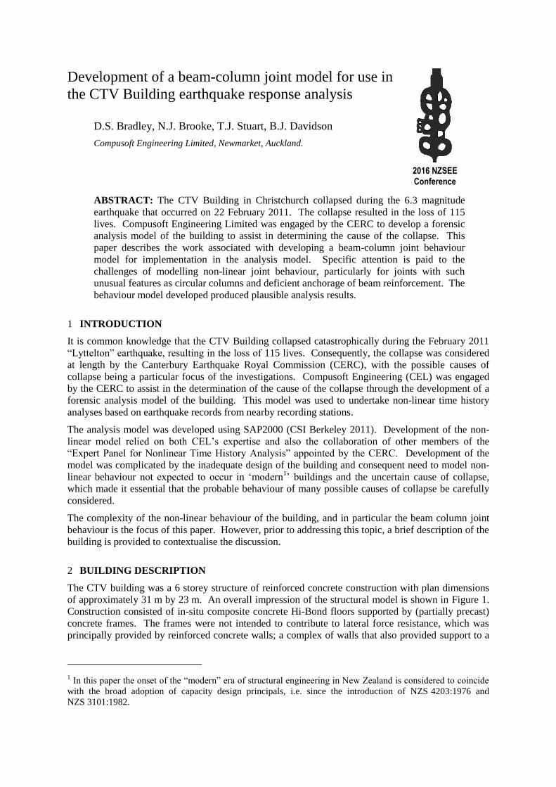
Figure 7 shows a comparison of the joint shear strength coefficient for interior joints according to
U.S. practice, New Zealand practice, and with modification to U.S. practice based on the work of Park
(2010). It is clear that there is a marked difference between these predictions. Lehman et al. (2004)
and Moehle (2006) have stated that the strengths given by ASCE 41 can be highly conservative, with
γ coefficients as high as 25. These observations suggest that the method used in NZ practice is more
realistic, and for this reason this methodology was adopted. Thus the joint capacity was based on
appropriate limits for joint core principal tension and principal compression stresses:
The limiting value for the principal tension stress was calculated as '
cmaxtp, fkf (NZSEE
2006), with the value of k determined from Figure 8 assuming the curvature ductility of the
adjacent member was zero;
The limiting value for the principal compression stress in the joint core was taken as '
cmaxcp, f0.5f based on a recommendation made by Priestley (1997).
-28.9
-18.9
-8.9
1.1
11.1
21.1
-2000
-1500
-1000
-500
0
500
1000
1500
2000
-0.03 -0.02 -0.01 0 0.01 0.02 0.03
Join
t sh
ear
str
ess
/sq
rt f
'c
Join
t sh
ear
str
ess
(P
SI)
Joint shear strain (radians)
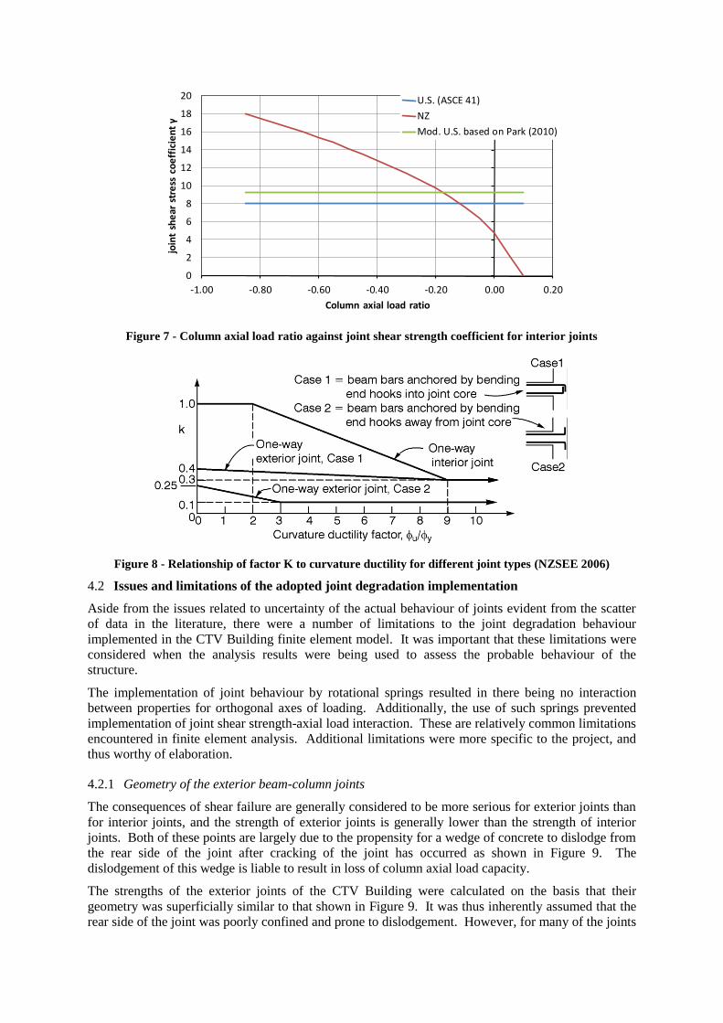
Figure 7 - Column axial load ratio against joint shear strength coefficient for interior joints
Figure 8 - Relationship of factor K to curvature ductility for different joint types (NZSEE 2006)
4.2 Issues and limitations of the adopted joint degradation implementation
Aside from the issues related to uncertainty of the actual behaviour of joints evident from the scatter
of data in the literature, there were a number of limitations to the joint degradation behaviour
implemented in the CTV Building finite element model. It was important that these limitations were
considered when the analysis results were being used to assess the probable behaviour of the
structure.
The implementation of joint behaviour by rotational springs resulted in there being no interaction
between properties for orthogonal axes of loading. Additionally, the use of such springs prevented
implementation of joint shear strength-axial load interaction. These are relatively common limitations
encountered in finite element analysis. Additional limitations were more specific to the project, and
thus worthy of elaboration.
4.2.1 Geometry of the exterior beam-column joints
The consequences of shear failure are generally considered to be more serious for exterior joints than
for interior joints, and the strength of exterior joints is generally lower than the strength of interior
joints. Both of these points are largely due to the propensity for a wedge of concrete to dislodge from
the rear side of the joint after cracking of the joint has occurred as shown in Figure 9. The
dislodgement of this wedge is liable to result in loss of column axial load capacity.
The strengths of the exterior joints of the CTV Building were calculated on the basis that their
geometry was superficially similar to that shown in Figure 9. It was thus inherently assumed that the
rear side of the joint was poorly confined and prone to dislodgement. However, for many of the joints
0
2
4
6
8
10
12
14
16
18
20
-1.00 -0.80 -0.60 -0.40 -0.20 0.00 0.20
join
t sh
ear
str
ess
co
eff
icie
nt γ
Column axial load ratio
U.S. (ASCE 41)
NZ
Mod. U.S. based on Park (2010)

this assumption was not accurate due to the existence (shown in Figure 10) of concrete elements
located at the rear face of the joint extending a significant distance beyond the column cross section.
This concrete could be expected to provide additional confinement to the rear side of the joint core,
and would hence be likely to enhance the strength of the joint core. This effect was not accounted for
in the analyses undertaken.
Figure 9 - Damage of exterior joint (left) observed during testing and (right) illustrated schematically (from Pampanin et al. 2002)
Figure 10 - Plan views of CTV Building exterior joints (Design Engineer 1986)
4.2.2 Dependence of joint behaviour on deformation of adjacent members
It is identified in the literature that the strength of beam-column joints is not a unique value dependent
only on joint core properties (dimensions, concrete strength etc.). Rather, the strength is also
dependent on the plastic deformation of the members framing into the beam-column joint (Priestley
1997). The significance of this relationship can be seen in Figure 8, which indicates that the joint
shear capacity of interior joints drops by 70% as the curvature ductility imposed on the adjacent
members increases from two to nine. The joint model implemented in the CTV Building model did
not implement this relationship between member curvature and joint capacity. Implementation of
such behaviour is extremely challenging in a finite element model.
4.2.3 Hook anchor capacity
The uncertainty regarding the performance of the beam column joints in the CTV Building was
significantly increased due to the possibility that deficiently-anchored beam bars could pull-out from
the joint core. The method of construction used for the CTV building required that the bottom

reinforcement of the beams typically be terminated at each column, with reinforcement being hooked
into the joint at these locations. Based on the engineering drawings (see Figure 11) the hook length
for the H28 or H24 bars was approximately 275 mm, which was less than half the length specified by
Standards as necessary to sustain ductile yielding of the bars (NZS 3101 2006).
Figure 11 - CTV building hook detail (Design Engineer 1986)
Work published by Joh et al. (Joh et al. 1993; Joh and Shibata 1996) provided a basis for determining
the anchorage capacity for the bar anchorages. Joh et al. identified three failure modes for hooked
anchorages, namely side splitting, local compression failure at the bar bend, and “raking-out” failure
or pull-out of the entire bar group (see Figure 12). Based on experimental tests they suggested a
method for determining the capacity of hooks based on raking-out failure. According to their method
the anchor strength is dependent on the column axial force, the embedment length, and the amount of
joint core reinforcement. The assessment method suggested significant bar anchorage can be
expected even when hook lengths are severely deficient according to NZS 3101:2006.
The postulated complex relationship between axial demand and anchorage capacity could not be
implemented analytically using the chosen joint model, and in any case no guidance was available
regarding interaction between joint shear demands and demands induced by the anchorages. Thus the
behaviour of the CTV Building hook anchorages was assessed by post-processing the results of the
analyses. This revealed that anchorage failure could have occurred prior to the occurrence of peak
joint shear demands. Neither crushing at the bend nor side splitting failure were considered likely to
have occurred; for the latter of these failure types the conclusion was somewhat uncertain due to a
lack of guidance on how to determine the side split strength for circular columns.
Figure 12 - Hooked anchorage failure modes (from Joh and Shibata 1996)
5 MODEL PERFORMANCE
For implementation into the overall analysis model, a series of backbone curves representing various

levels of column axial load and each direction of loading were developed for each beam-column joint
geometry using the behaviour model described in the previous section; an example of these curves is
presented in Figure 13.
Figure 13 - Backbone curve eastern frame joint
Figures 14 and 15 present results obtained for a selection of beam-column joints. As can be seen from
the plots, the hysteretic behaviour of the beam-column joints indicates non-linear response of the
joints was predicted to occur. Figure 15 illustrates a significant amount of strength degradation, along
with very large rotations occurring at the point of global building failure.
Figure 14 - Example of eastern frame beam-column joint hysteretic behaviour (left) and joint rotation (rotation) time history results.
Figure 15 - Example of western frame beam-column joint hysteretic behaviour (left) and joint rotation (right) time history results.
Using the adopted joint model, the time history analyses ran very smoothly. The simplicity of the
model allowed quick checks and testing to be undertaken, vastly reducing development and analysis
time. Moment rotation results show a good correlation with pinched hysteretic behaviour observed in

beam-column joint tests. Joint strength and stiffness degradation occurred at a number of beam
column joints and analyses predicted that beam column joint failure was a potential cause of collapse.
6 CONCLUSIONS
Forensic analysis requires a structure to be modelled as accurately as possible to capture its probable
behaviour. Achieving this requires careful consideration of critical elemental behaviour; determining
appropriate behaviour models for deficient elements is typically challenging. This is particularly true
for the non-linear modelling of beam column joints as the body of knowledge concerning the
performance of beam-column joints is limited. Numerous challenges were encountered during
development of the joint behaviour model. Conclusions drawn as a result of addressing these
challenges included:
The literature shows there is uncertainty about both the strength and strength-deformation
behaviour of deficient beam-column joints;
The current state of knowledge is not sufficient to allow accurate prediction of the behaviour
of deficient beam-column joints. Thus it is questionable whether increased accuracy of
prediction would be achieved by use of complex multi-element models of beam-column
joints; and
There is a particular paucity of information in the literature about the performance of beam-
column joints containing circular columns, the behaviour of deficient hooked anchorages, and
the interaction between such anchorages and joint behaviour. Further research on all these
factors would be desirable.
The accuracy of the predicted joint behaviour cannot be definitively determined. However,
the results obtained through implementation of a simple non-linear spring model appear to be
plausible and correlated well with available experimental data. Furthermore, results
corresponded well with collapse hypotheses determined by various experts involved in the
CERC;
The principal limitations of spring model were the inability to capture variations of various
effects (e.g. axial load and biaxial effects) during the course of the analysis. These
disadvantages were offset by the benefits of the approach being computationally efficient and
stable, easy to implement, test, and providing results that were convenient for post-
processing;
REFERENCES
Alire, D. A. (2002) Seismic Evaluation of Existing Unconfined Reinforced Concrete Beam-Column Joints. Master‟s Thesis, University of Washington, Seattle, Washington, 306p.
ASCE. (2006) ASCE 41-06 Seismic Rehabilitation of Existing Buildings. American Society of Civil Engineers, Reston, Virginia, 411p.
Birely, A., Lowes, L. N., and Lehman, D. E. (2012) “A Model for the Practical Nonlinear Analysis of Reinforced-Concrete Frames Including Joint Flexibility.” Engineering Structures, 34, pp.455–465.
Clyde, C., Pantelides, C. P., and Reaveley, L. D. (2000) Performance-Based Evaluation of Exterior Reinforced Concrete Building Joints for Seismic Excitation. PEER 2000/05, Pacific Earthquake Engineering Research Center, Berkeley, California, 50p.
Compusoft Engineering Limited. (2012) CTV Building: Non-Linear Time History Analysis (NLTHA) Report. 12026-00, Auckland, New Zealand, 305p.
Cooper, M. C., Carter, R., and Fenwick, R. C. (2012) Final Report Volume 6: Canterbury Television Building (CTV). Canterbury Earthquakes Royal Commission, Christchurch, New Zealand, 324p.
CSI Berkeley. (2011) Computer program SAP2000 v15.0.1. Computers and Structures Inc., Berkeley, California.
Design Engineer. (1986) Structural Drawings: Office Building - 249 Madras Street. Set No. 7, Issued 30 September, 39p.
Dowell, R. K., Seible, F., and Wilson, E. L. (1998) “Pivot Hysteresis Model for Reinforced Concrete Members.”

ACI Structural Journal, 95(5), pp.607–616.
Joh, O., Goto, Y., and Shibata, T. (1993) “Anchorage of Beam Bars with 90-Degree Bend in Reinforced Concrete Beam-Column Joints.” Tom Paulay Symposium “Recent Developments in Lateral Force Transfer in Buildings,” University of California, San Diego, La Jolla, California, 97–116p.
Joh, O., and Shibata, T. (1996) “Anchorage Behaviour of 90-Degree Hooked Beams in Reinforced Concrete Beam-Column Joints.” Eleventh World Conference on Earthquake Engineering, Acapulco, Mexico.
Kam, W. Y. (2010) Selective Weakening and Post-Tensioning for the Seismic Retrofit of Non-Ductile RC Frames. PhD Thesis, The University of Canterbury, Christchurch, New Zealand, 672p.
Kurose, Y. (1987) Recent Studies on Reinforced Concrete Beam-Column Joints in Japan. Phil M. Ferguson Structural Engineering Laboratory, The University of Texas, Austin, Texas, 164p.
Lehman, D. E., Stanton, J. F., Anderson, M., Alire, D. A., and Walker, S. G. (2004) “Seismic Performance of Older Beam-Column Joints.” 13th World Conference on Earthquake Engineering, Vancouver, Canada.
Mitra, N., and Lowes, L. N. (2007) “Evaluation, Calibration, and Verification of a Reinforced Concrete Beam-Column Joint Model.” ASCE Journal of Structural Engineering, 133(1), pp.105–120.
Moehle, J. P., Lehman, D., and Lowes, L. N. (2006) “Beam-Column Connections.” PEER/EERI Seminar on Nonductile Concrete, Accessed at: peer.berkeley.edu/ research/ powerpoint/ non_ductible_concrete/Joints - Moehle c.ppt (Jun. 15, 2012).
NZS 3101. (2006) Concrete Structures Standard. Standards New Zealand, Wellington, New Zealand, 646p.
NZSEE. (2006) Assessment and Improvement of the Structural Performance of Buildings in Earthquakes. New Zealand Society for Earthquake Engineering, Wellington, New Zealand, ~400p.
Pampanin, S., Calvi, G. M., and Moratti, M. (2002) “Seismic Behaviour of RC Beam-Column Joints Designed for Gravity Loads.” 12th European Conference on Earthquake Engineering, Elsevier Science Ltd., London, England.
Pantelides, C. P., Hansen, J., and Nadauld, J. (2002) Performance-Based Evaluation of Exterior Reinforced Concrete Building Joints for Seismic Excitation. PEER 2002/18, Pacific Earthquake Engineering Research Center, Berkeley, California, 103p.
Park, S. (2010) Experimental and Analytical Studies on Old Reinforced Concrete Buildings with Seismically Vulnerable Beam-Column Joints. PhD Thesis, University of California, Berkeley, 260p.
Priestley, M. J. N. (1997) “Displacement-Based Seismic Assessment of Reinforced Concrete Buildings.” Journal of Earthquake Engineering, 1(1), pp.157–192.
Sharma, A., Eligehausen, R., and Reddy, G. R. (2011) “A New Model to Simulate Joint Shear Behaviour of Poorly Detailed Beam-Column Connections in RC Structures Under Seismic Loads, Part 1: Exterior Joints.” Engineering Structures, 33, pp.1034–1051.
Walker, S. G. (2001) Seismic Performance of Existing Reinforced Concrete Beam-Column Joints. Master‟s Thesis, University of Washington, Seattle, Washington, 326p.