
Development Lines of Improved Physical Modeling at DLR
53
Development Lines of Improved Physical Modeling at DLR a Window on Science Seminar 24 September 2018 a a US Air Force Research Laboratory (AFRL) Wright-Patterson Air Force Base, OH, USA Andreas Krumbein, Bernhard Eisfeld, Tobias Knopp, Normann Krimmelbein, Axel Probst, Silvia Probst, Vamshi Togiti, Marco Burnazzi, Daniela François, Philip Ströer a DLR, Institute for Aerodynamic and Flow Technology C 2 A 2 S 2 E, Turbulence & Transition Group
Transcript of Development Lines of Improved Physical Modeling at DLR

Development Lines of Improved Physical Modeling at DLR a
Window on Science Seminar 24 September 2018 a a
US Air Force Research Laboratory (AFRL) Wright-Patterson Air Force Base, OH, USA
Andreas Krumbein, Bernhard Eisfeld, Tobias Knopp, Normann Krimmelbein, Axel Probst, Silvia Probst, Vamshi Togiti, Marco Burnazzi, Daniela François, Philip Ströer a
DLR, Institute for Aerodynamic and Flow Technology C2A2S2E, Turbulence & Transition Group

STELAR 2. Projekttreffen > DLR Göttingen > 23.04.2012
Slide 2
www.DLR.de • Folie 2 > Development Lines of Improved Physical Modeling at DLR > Andreas Krumbein • Wright-Patterson AFB, OH, USA > 24 September 2018
The German Aerospace Center - DLR
Three primary functions National aeronautics and space research center of the Federal Republic of Germany
• Personnel: ~ 6000 Germany’s space agency
Personnel: ~ 6000 One (out of a number of) project management agencies for national research projects

STELAR 2. Projekttreffen > DLR Göttingen > 23.04.2012
Slide 3
www.DLR.de • Folie 3 > Development Lines of Improved Physical Modeling at DLR > Andreas Krumbein • Wright-Patterson AFB, OH, USA > 24 September 2018
The German Aerospace Center - DLR
Three primary functions National aeronautics and space research center of the Federal Republic of Germany
Personnel: ~ 6000 Germany’s space agency
Personnel: ~ 800 One (out of a number of) project management agencies for national research projects
Personnel: ~ 1200

STELAR 2. Projekttreffen > DLR Göttingen > 23.04.2012
Slide 4
www.DLR.de • Folie 4 > Development Lines of Improved Physical Modeling at DLR > Andreas Krumbein • Wright-Patterson AFB, OH, USA > 24 September 2018
The German Aerospace Center - DLR
Three primary functions National aeronautics and space research center of the Federal Republic of Germany
Personnel: ~ 6000 Germany’s space agency
Personnel: ~ 800 One (out of a number of) project management agencies for national research projects
Personnel: ~ 1200
8100 employees in 40 institutes at 20 sites in Germany
headquarters
6 research areas: Aeronautics Space Energy Transport Digitalisation (new) Security (new)
6 research areas: Aeronautics Space Energy Transport Digitalisation (new) Security (new)
Institute for Aerodynamic and Flow Technology
Göttingen: L. Prandtl, H. Schlichting, W. Tollmien, Th. von Kármán, …
Braunschweig: H. Blenk, A. Busemann, …

STELAR 2. Projekttreffen > DLR Göttingen > 23.04.2012
Slide 5
www.DLR.de • Folie 5 > Development Lines of Improved Physical Modeling at DLR > Andreas Krumbein • Wright-Patterson AFB, OH, USA > 24 September 2018
Research and work areas Software Development Aircraft Aerodynamics Aircraft Design and Assessment Experimental Methods Military Aircraft Helicopter Aerodynamics High-Speed-Configurations Spacecraft Aeroacoustics Technical Flows Flow Measurement Technology Acoustic Measurement Technology Hardware
Institute for Aerodynamic and Flow Technology

STELAR 2. Projekttreffen > DLR Göttingen > 23.04.2012
Slide 6
www.DLR.de • Folie 6 > Development Lines of Improved Physical Modeling at DLR > Andreas Krumbein • Wright-Patterson AFB, OH, USA > 24 September 2018
Research and work areas Software Development Aircraft Aerodynamics Aircraft Design and Assessment Experimental Methods Military Aircraft Helicopter Aerodynamics High-Speed-Configurations Spacecraft Aeroacoustics Technical Flows Flow Measurement Technology Acoustic Measurement Technology Hardware
Institute for Aerodynamic and Flow Technology

STELAR 2. Projekttreffen > DLR Göttingen > 23.04.2012
Slide 7
www.DLR.de • Folie 7 > Development Lines of Improved Physical Modeling at DLR > Andreas Krumbein • Wright-Patterson AFB, OH, USA > 24 September 2018
Outline
Introduction Reynolds stress models (RSM) Scale resolving simulations (SRS) Transition prediction and modeling Turbulence modeling improvements Outlook

STELAR 2. Projekttreffen > DLR Göttingen > 23.04.2012
Slide 8
www.DLR.de • Folie 8 > Development Lines of Improved Physical Modeling at DLR > Andreas Krumbein • Wright-Patterson AFB, OH, USA > 24 September 2018
Introduction Overview C²A²S²E – Numerical Methods Branch → CFD Code Development
TAU code – external aerodynamics, unstructered, FV, compressible → air vehicles THETA code – internal/external flows, unstructered, FV, incompressible → combustion, wind turbines, two-phase flows (gas/liquid) Flucs (FLexible Unstructured CFD Software) – external aerodynamics
→ DLR’s ‘next generation’ flow solver → unstructured, 2nd order FV branch + HO-DG-branch, compressible/incompressible → massive hybrid parallelization → flow-solver component of a multi-disciplinary simulation system FlowSimulator → development currently ongoing → 1st release planned for 12/2021 Main Customers
Internal: Transport Aircraft, Helicopters (incl. Wind Turbines), High-Speed Configurations, Spacecraft External: Airbus Operations
Focus: Transport Type Aircraft

STELAR 2. Projekttreffen > DLR Göttingen > 23.04.2012
Slide 9
www.DLR.de • Folie 9 > Development Lines of Improved Physical Modeling at DLR > Andreas Krumbein • Wright-Patterson AFB, OH, USA > 24 September 2018
Our major driver: The Digital Aircraft Numerical Analysis of Full Flight Envelope
Extension of confidence region towards edge of flight envelope
Unsteady flows Strong non-linearities
Separated flow regions Strong shocks Shock/boundary-layer interaction …
CFD solver capabilities growing Discretization schemes Grid generation, higher resolution, geometrical complexity and details, … HPC capacities and parallelization strategies …
Turbulence and transition models have to keep up with solver capabilities. Coupling and extension of models needed.
cruise point
normaloperational range
borders of theflight envelopeBuffet boundary
Maximum lift
High lift
Unsteady effects
cruise point
normaloperational range
borders of theflight envelopeBuffet boundary
Maximum lift
High lift
Unsteady effects
Courtesy: Airbus Grey gradient indicates level of
confidence in CFD flow solutions
Buffet boundary

STELAR 2. Projekttreffen > DLR Göttingen > 23.04.2012
Slide 10
www.DLR.de • Folie 10 > Development Lines of Improved Physical Modeling at DLR > Andreas Krumbein • Wright-Patterson AFB, OH, USA > 24 September 2018
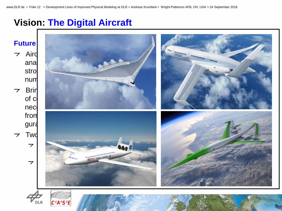
Vision: The Digital Aircraft Future goal for CFD
Aircraft design and analysis based strongly on numerical simulation Bring down number of computations necessary and free from current confi- guration knowledge Two basic concepts
Time accurate maneuver simulations: Flying the equations Generation of aerodynamic/aeroelastic data: Flying through the data base

STELAR 2. Projekttreffen > DLR Göttingen > 23.04.2012
Slide 11
www.DLR.de • Folie 11 > Development Lines of Improved Physical Modeling at DLR > Andreas Krumbein • Wright-Patterson AFB, OH, USA > 24 September 2018
Vision: The Digital Aircraft Future goal for CFD
Aircraft design and analysis based strongly on numerical simulation Bring down number of computations necessary and free from current confi- guration knowledge Two basic concepts
Time accurate maneuver simulations: Flying the equations → Physical Modeling for High Fidelity CFD Generation of aerodynamic/aeroelastic data: Flying through the data base
STELAR 2. Projekttreffen > DLR Göttingen > 23.04.2012
Slide 12
www.DLR.de • Folie 12 > Development Lines of Improved Physical Modeling at DLR > Andreas Krumbein • Wright-Patterson AFB, OH, USA > 24 September 2018
Vision: The Digital Aircraft Future goal for CFD
Aircraft design and analysis based strongly on numerical simulation Bring down number of computations necessary and free from current confi- guration knowledge Two basic concepts
Time accurate maneuver simulations: Flying the equations → Physical Modeling for High Fidelity CFD Generation of aerodynamic/aeroelastic data: Flying through the data base

STELAR 2. Projekttreffen > DLR Göttingen > 23.04.2012
Slide 13
www.DLR.de • Folie 13 > Development Lines of Improved Physical Modeling at DLR > Andreas Krumbein • Wright-Patterson AFB, OH, USA > 24 September 2018
Vision: The Digital Aircraft Numerical Analysis of Full Flight Envelope
For accurate predictions, besides high grid resolution and accurate numerical handling of the equations physical modeling is a key issue. Four development lines: 1. Reynolds stress models (RSM)
As standard RANS approach for any kind of configuration (including highly complex industrial configurations)
2. Scale resolving simulations (SRS) Targeted application for specific components of aircraft or military configurations
3. Transition prediction and modeling Necessary condition for accurate results of turbulence models within the full flight envelope
4. Turbulence modeling improvements Targeted experimental (physical & numerical) investigations for specific flow phenomena

STELAR 2. Projekttreffen > DLR Göttingen > 23.04.2012
Slide 14
www.DLR.de • Folie 14 > Development Lines of Improved Physical Modeling at DLR > Andreas Krumbein • Wright-Patterson AFB, OH, USA > 24 September 2018
Reynolds stress models Differential RSM (DRSM)
DRSM represent highest level of RANS-modeling Individual equations for stress components Anisotropy of turbulence inherently accounted for Effects of rotation and streamline curvature included No corrections for free vortices necessary No stagnation point anomaly 7 model equations
Sometimes lack of robustness for complex configurations DRSM in TAU
SSG/LRR-ω model (standard model)
Based on Menter’s BSL ω-equation Exact transformation to g = 1/ 𝜔𝜔 and to 𝜔𝜔�= ln(𝜔𝜔)
Higher numerical stability + no near wall grid dependence εh-JHh-v2 model (Jakirlic-Hanjalic + ISM of TU-BS)
Based on homogeneous dissipation rate εh
Advanced near-wall treatment + anisotropic dissipation
SSG/LRR-ω
Better prediction of multiple vortices
Simpson wing Re = 1.3×10⁶
M = 0.077)
SSG/LRR-g
RSM SA
a breakthrough?
only one vortex

STELAR 2. Projekttreffen > DLR Göttingen > 23.04.2012
Slide 15
www.DLR.de • Folie 15 > Development Lines of Improved Physical Modeling at DLR > Andreas Krumbein • Wright-Patterson AFB, OH, USA > 24 September 2018
Reynolds stress models Application of Reynolds Stress Models Realistic aircraft configuration Re = 40×106, M = 0.85, α = 2.0°
shock position
complex separation
Significant better shock prediction Very different separation pattern
STELAR 2. Projekttreffen > DLR Göttingen > 23.04.2012
Slide 16
www.DLR.de • Folie 16 > Development Lines of Improved Physical Modeling at DLR > Andreas Krumbein • Wright-Patterson AFB, OH, USA > 24 September 2018
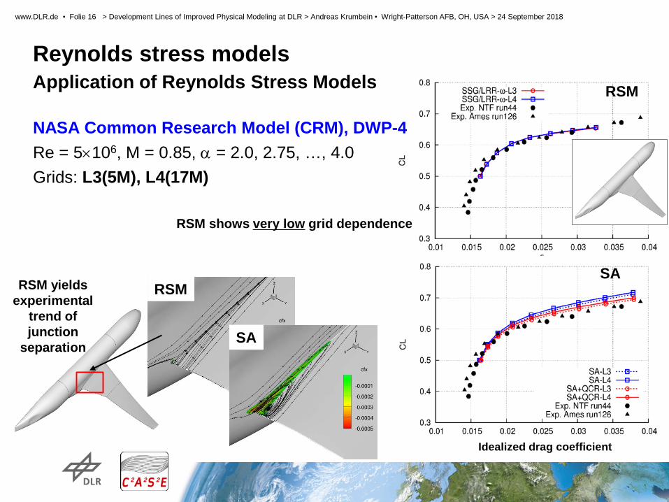
Reynolds stress models Application of Reynolds Stress Models
RSM
Idealized drag coefficient
SA RSM
SA
RSM yields experimental
trend of junction
separation
NASA Common Research Model (CRM), DWP-4 Re = 5×10⁶, M = 0.85, α = 2.0, 2.75, …, 4.0 Grids: L3(5M), L4(17M)
RSM shows very low grid dependence
STELAR 2. Projekttreffen > DLR Göttingen > 23.04.2012
Slide 17
www.DLR.de • Folie 17 > Development Lines of Improved Physical Modeling at DLR > Andreas Krumbein • Wright-Patterson AFB, OH, USA > 24 September 2018
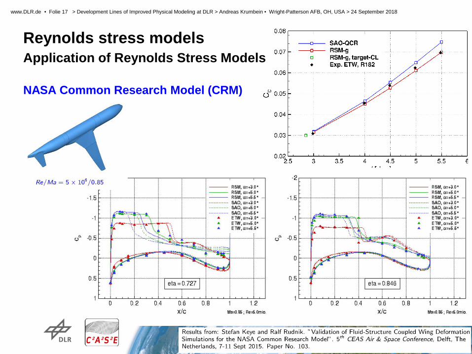
Reynolds stress models Application of Reynolds Stress Models NASA Common Research Model (CRM)
STELAR 2. Projekttreffen > DLR Göttingen > 23.04.2012
Slide 18
www.DLR.de • Folie 18 > Development Lines of Improved Physical Modeling at DLR > Andreas Krumbein • Wright-Patterson AFB, OH, USA > 24 September 2018
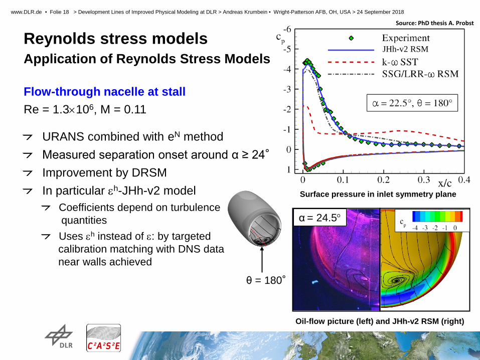
Reynolds stress models Application of Reynolds Stress Models Flow-through nacelle at stall Re = 1.3×10⁶, M = 0.11
URANS combined with eN method Measured separation onset around α ≥ 24° Improvement by DRSM In particular εh-JHh-v2 model
Coefficients depend on turbulence quantities Uses εh instead of ε: by targeted
calibration matching with DNS data near walls achieved
θ = 180°
JHh-v2 RSM
α = 24.5°
Oil-flow picture (left) and JHh-v2 RSM (right)
Surface pressure in inlet symmetry plane
Source: PhD thesis A. Probst

STELAR 2. Projekttreffen > DLR Göttingen > 23.04.2012
Slide 19
www.DLR.de • Folie 19 > Development Lines of Improved Physical Modeling at DLR > Andreas Krumbein • Wright-Patterson AFB, OH, USA > 24 September 2018
Scale resolving simulations Basic approach
Classical hybrid RANS/LES models Detached-Eddy Simulation (DES, 1997) Delayed DES (DDES, 2006) Improved DDES (IDDES, 2008) Coupled with SA or k-ω type RANS models
Numerics 2nd order central spatial discretization of all equations 4th order matrix artificial dissipation with k(4) = 1/128 Skew-symmetric convective fluxes (for kinetic energy conservation)
Low Mach number preconditioning (LMP) for M < 0.3 2nd order dual-time stepping
Range of applicability Flows with massive local separations Clear distinction between attached (stable) and
separated (unstable) regions
NASA CRM at low speed and high AoA
DLR-F15 3-element high-lift airfoil near maximum lift

STELAR 2. Projekttreffen > DLR Göttingen > 23.04.2012
Slide 20
www.DLR.de • Folie 20 > Development Lines of Improved Physical Modeling at DLR > Andreas Krumbein • Wright-Patterson AFB, OH, USA > 24 September 2018
Scale resolving simulations Sample applications of basic approach NASA tandem cylinder
Experimental setup in WT
TAU results: green
SA-DDES
Snapshot of spanwise vorticity
Downstream Cylinder
• Good prediction all approaches on both cylinders • Influence of numerical method and underlying RANS model small
Downstream Cylinder
Pressure fluctuations Mean pressure
•L/D = 3.7 •M = 0.1285 •ReD = 1.66×10⁵
• k-ω based models too “noisy” → Reason unclear

STELAR 2. Projekttreffen > DLR Göttingen > 23.04.2012
Slide 21
www.DLR.de • Folie 21 > Development Lines of Improved Physical Modeling at DLR > Andreas Krumbein • Wright-Patterson AFB, OH, USA > 24 September 2018
Scale resolving simulations Sample applications of basic approach NASA tandem cylinder
Experimental setup in WT
TAU results: green
SA-DDES
Snapshot of spanwise vorticity
Downstream Cylinder
• Good prediction all approaches on both cylinders • Influence of numerical method and underlying RANS model small
Downstream Cylinder
Pressure fluctuations Mean pressure
•L/D = 3.7 •M = 0.1285 •ReD = 1.66×10⁵
• k-ω based models too “noisy” → Reason unclear
URANS with different turbulence models

STELAR 2. Projekttreffen > DLR Göttingen > 23.04.2012
Slide 22
www.DLR.de • Folie 22 > Development Lines of Improved Physical Modeling at DLR > Andreas Krumbein • Wright-Patterson AFB, OH, USA > 24 September 2018
Scale resolving simulations Extended approach
Improved Numerics Better satisfying general LES requirements
→ Very high accuracy → low dissipation (LD) and low dispersion (LD2)
LD2-scheme: 2nd-order central scheme with Reduced dissipation settings (optimized)
Reduced dispersion by appropriate flux reconstruction
Test with pure LES applications, e.g. periodic 2D channel flow
Switch of standard RANS scheme into LD2 scheme for LES: apply optimized numerics in LES regions only → Adaptive numerical scheme for hybrid RANS/LES computations
Resolved Reynolds stresses
WR-LES: given Reδ (mass flow), target
quantity Reτ (wall shear stress)
Reτ
DNS 395
Ref. Num. 358
LD 389
LD2 393
Velocity profile
LES
STELAR 2. Projekttreffen > DLR Göttingen > 23.04.2012
Slide 23
www.DLR.de • Folie 23 > Development Lines of Improved Physical Modeling at DLR > Andreas Krumbein • Wright-Patterson AFB, OH, USA > 24 September 2018
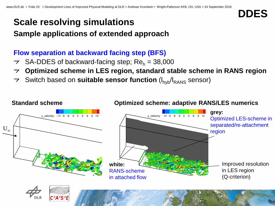
Scale resolving simulations Sample applications of extended approach Flow separation at backward facing step (BFS)
SA-DDES of backward-facing step; Reh = 38,000 Optimized scheme in LES region, standard stable scheme in RANS region Switch based on suitable sensor function (lhyb/lRANS sensor)
Standard scheme Optimized scheme: adaptive RANS/LES numerics
U∞
Improved resolution in LES region (Q-criterion)
grey: Optimized LES-scheme in separated/re-attachment region
white: RANS-scheme in attached flow
DDES
STELAR 2. Projekttreffen > DLR Göttingen > 23.04.2012
Slide 24
www.DLR.de • Folie 24 > Development Lines of Improved Physical Modeling at DLR > Andreas Krumbein • Wright-Patterson AFB, OH, USA > 24 September 2018
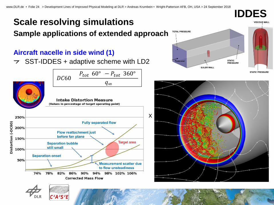
Scale resolving simulations Sample applications of extended approach Aircraft nacelle in side wind (1)
SST-IDDES + adaptive scheme with LD2
x
IDDES
𝐷𝐷𝐷𝐷𝐷𝐷 =𝑃𝑃𝑡𝑡𝑡𝑡𝑡𝑡(𝐷𝐷°) − 𝑃𝑃𝑡𝑡𝑡𝑡𝑡𝑡(3𝐷𝐷°)
𝑞𝑞∞

STELAR 2. Projekttreffen > DLR Göttingen > 23.04.2012
Slide 25
www.DLR.de • Folie 25 > Development Lines of Improved Physical Modeling at DLR > Andreas Krumbein • Wright-Patterson AFB, OH, USA > 24 September 2018
Scale resolving simulations Sample applications of extended approach Aircraft nacelle in side wind (2)
SST-IDDES + adaptive scheme with LD2
IDDES
LD2 scheme Reference scheme
Shock-induced separation
IDDES
IDDES k-w SST
Target area
RANS k-w SST
1
2 3
STELAR 2. Projekttreffen > DLR Göttingen > 23.04.2012
Slide 26
www.DLR.de • Folie 26 > Development Lines of Improved Physical Modeling at DLR > Andreas Krumbein • Wright-Patterson AFB, OH, USA > 24 September 2018
Scale resolving simulations Extended approach
Improved Modeling → Towards extension of the applicability range from massive to incipient separation
Three areas 1. RANS/LES sensors for pressure-induced separation 2. Acceleration of transition from RANS to LES ( → „grey area“ mitigation)
3. Underlying RANS model ( → better representation of separation point)
1. RANS/LES sensors for pressure-induced separation Shortcomings of DDES
No reliable “shielding” of attached BLs No clear RANS/LES interface at separation
DLR development Algebraic DDES (ADDES) Boundary-layer (BL) detection Separation detection Algebraic RANS/LES sensor
STELAR 2. Projekttreffen > DLR Göttingen > 23.04.2012
Slide 27
www.DLR.de • Folie 27 > Development Lines of Improved Physical Modeling at DLR > Andreas Krumbein • Wright-Patterson AFB, OH, USA > 24 September 2018
Scale resolving simulations Extended approach
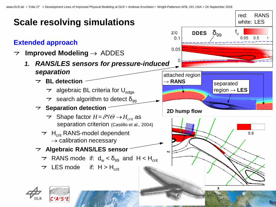
Improved Modeling → ADDES 1. RANS/LES sensors for pressure-induced
separation BL detection
algebraic BL criteria for Uedge
search algorithm to detect δ99 Separation detection
Shape factor H = δ*/Θ → Hcrit as separation criterion (Castillo et al., 2004)
Hcrit RANS-model dependent → calibration necessary
Algebraic RANS/LES sensor RANS mode if: dw < δ99 and H < Hcrit
LES mode if: H > Hcrit
δ99
separated region → LES
2D hump flow
attached region → RANS
red: RANS white: LES

STELAR 2. Projekttreffen > DLR Göttingen > 23.04.2012
Slide 28
www.DLR.de • Folie 28 > Development Lines of Improved Physical Modeling at DLR > Andreas Krumbein • Wright-Patterson AFB, OH, USA > 24 September 2018
Scale resolving simulations Extended approach
Improved Modeling → ADDES
Automatic injection of synthetic turbulence under development
RANS region
WM-LES region
synthetic turbulence plane
Demonstration of separation detection

STELAR 2. Projekttreffen > DLR Göttingen > 23.04.2012
Slide 29
www.DLR.de • Folie 29 > Development Lines of Improved Physical Modeling at DLR > Andreas Krumbein • Wright-Patterson AFB, OH, USA > 24 September 2018
Scale resolving simulations Extended approach 2. Acceleration of transition from RANS to LES
Hybrid RANS/LES of incipient separation suffers from “grey area”:
Weak separations rather stable w.r.t. outer disturbances Hybrid RANS/LES switches to LES mode, but resolved turbulence is delayed
Undefined modelling state with low total (modelled + resolved) turbulent stress
Techniques for grey area mitigation considered in TAU code: 1. Stochastic forcing of modeled turbulence 2. Modified LES scale considering local vorticity vector
• Both 1. and 2. applicable to rather unstable separation or free shear flow 3. Synthetic turbulence generated from RANS data
• Complex approach, but applicable to weakly separated or attached flow
SST-ADDES
RANS LES

STELAR 2. Projekttreffen > DLR Göttingen > 23.04.2012
Slide 30
www.DLR.de • Folie 30 > Development Lines of Improved Physical Modeling at DLR > Andreas Krumbein • Wright-Patterson AFB, OH, USA > 24 September 2018
Scale resolving simulations Extended approach
Improved Modeling → Synthetic turbulence (RANS → LES)
2. Acceleration of transition from RANS to LES Initial implementation of Synthetic Eddy Method (SEM, 2006)
Artificial fluctuations generated from given turbulence statistics First tests with SEM applied at inflow boundary:
2D channel flow Rounded step with separation:
Ongoing:
Full integration in hybrid RANS/LES (i.e. combination with ADDES)
IDDES+SEM
IDDES
Q=850 1/s2 Method xseparation xreattachment
IDDES 1.15 6.04
IDDES + SEM 0.72 4.99
LES (reference) 0.83 4.36

STELAR 2. Projekttreffen > DLR Göttingen > 23.04.2012
Slide 31
www.DLR.de • Folie 31 > Development Lines of Improved Physical Modeling at DLR > Andreas Krumbein • Wright-Patterson AFB, OH, USA > 24 September 2018
Scale resolving simulations Extended approach
Improved Modeling → Synthetic turbulence (RANS → LES)
2D wall-mounted hump
time- and span-averaged skin friction
Snapshot of: λ2 = 5∙(U/c)2 (SST-IDDES + SEM(x=-1); mand. time step)
STELAR 2. Projekttreffen > DLR Göttingen > 23.04.2012
Slide 32
www.DLR.de • Folie 32 > Development Lines of Improved Physical Modeling at DLR > Andreas Krumbein • Wright-Patterson AFB, OH, USA > 24 September 2018
Scale resolving simulations Extended approach
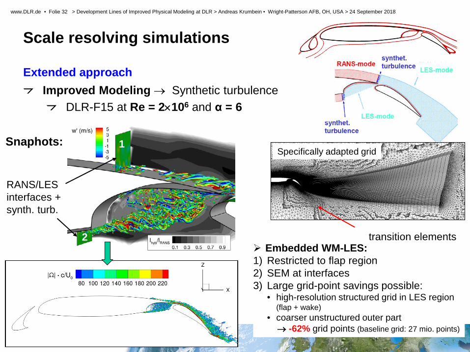
Improved Modeling → Synthetic turbulence
DLR-F15 at Re = 2×10⁶ and α = 6
Specifically adapted grid Snaphots: 1
2
RANS/LES interfaces + synth. turb.
Embedded WM-LES: 1) Restricted to flap region 2) SEM at interfaces 3) Large grid-point savings possible:
• high-resolution structured grid in LES region (flap + wake)
• coarser unstructured outer part → -62% grid points (baseline grid: 27 mio. points)
transition elements

STELAR 2. Projekttreffen > DLR Göttingen > 23.04.2012
Slide 33
www.DLR.de • Folie 33 > Development Lines of Improved Physical Modeling at DLR > Andreas Krumbein • Wright-Patterson AFB, OH, USA > 24 September 2018
Scale resolving simulations Extended approach
Improved Modeling → Synthetic turbulence
DLR-F15 at Re = 2×10⁶ and α = 6
reasonable agreement between different „zonal“ approaches
Cross-comparison with project partners from EU
project Go4Hybrid
Mean surface pressure: Mean skin friction:

STELAR 2. Projekttreffen > DLR Göttingen > 23.04.2012
Slide 34
www.DLR.de • Folie 34 > Development Lines of Improved Physical Modeling at DLR > Andreas Krumbein • Wright-Patterson AFB, OH, USA > 24 September 2018
Extended approach Improved Modeling → Modified LES scale using local vorticity vector (𝑁𝑁)
Transition from RANS to LES: Take into account local orientation of vortices
Δω = 𝑁𝑁𝑥𝑥2Δ𝑦𝑦,𝑚𝑚𝑚𝑚𝑥𝑥Δ𝑧𝑧,𝑚𝑚𝑚𝑚𝑥𝑥 + 𝑁𝑁𝑦𝑦2Δ𝑥𝑥,𝑚𝑚𝑚𝑚𝑥𝑥Δ𝑧𝑧,𝑚𝑚𝑚𝑚𝑥𝑥 + 𝑁𝑁𝑧𝑧2Δ𝑥𝑥,𝑚𝑚𝑚𝑚𝑥𝑥Δ𝑦𝑦,𝑚𝑚𝑚𝑚𝑥𝑥
Scale resolving simulations
Transonic nozzle jet flow: 𝜟𝜟𝒎𝒎𝒎𝒎𝒎𝒎 vs. 𝜟𝜟𝝎𝝎
Ufan
Ucore
𝑙𝑙𝐷𝐷𝐷𝐷𝐷𝐷𝐷𝐷 = 𝑓𝑓𝐷𝐷𝐷𝐷𝐷𝐷𝐷𝐷 (𝑙𝑙𝑅𝑅𝑅𝑅𝑅𝑅𝐷𝐷, 𝑙𝑙𝐿𝐿𝐷𝐷𝐷𝐷) with 𝑙𝑙𝐿𝐿𝐷𝐷𝐷𝐷 = 𝐷𝐷 ⋅ 𝚫𝚫𝝎𝝎
Use 𝜟𝜟𝝎𝝎 instead of 𝜟𝜟𝒎𝒎𝒎𝒎𝒎𝒎 = 𝒎𝒎𝒎𝒎𝒎𝒎 𝜟𝜟𝒎𝒎,𝜟𝜟𝒚𝒚,𝜟𝜟𝒛𝒛

STELAR 2. Projekttreffen > DLR Göttingen > 23.04.2012
Slide 35
www.DLR.de • Folie 35 > Development Lines of Improved Physical Modeling at DLR > Andreas Krumbein • Wright-Patterson AFB, OH, USA > 24 September 2018
Extended approach Improved Modeling → Modified LES scale
Scale resolving simulations
Engine line: Fan line:
• axial oscillations (Ma-cells) captured by all simulations • „wave length“ better predicted by HRLM (increasing phase shift with RANS)
Engine line
Fan line
STELAR 2. Projekttreffen > DLR Göttingen > 23.04.2012
Slide 36
www.DLR.de • Folie 36 > Development Lines of Improved Physical Modeling at DLR > Andreas Krumbein • Wright-Patterson AFB, OH, USA > 24 September 2018
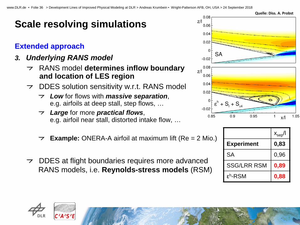
Scale resolving simulations Extended approach 3. Underlying RANS model
RANS model determines inflow boundary and location of LES region DDES solution sensitivity w.r.t. RANS model
Low for flows with massive separation, e.g. airfoils at deep stall, step flows, … Large for more practical flows, e.g. airfoil near stall, distorted intake flow, … Example: ONERA-A airfoil at maximum lift (Re = 2 Mio.)
DDES at flight boundaries requires more advanced
RANS models, i.e. Reynolds-stress models (RSM)
xsep/l
Experiment 0,83
SA 0,96
SSG/LRR RSM 0,89
εh-RSM 0,88
Quelle: Diss. A. Probst

STELAR 2. Projekttreffen > DLR Göttingen > 23.04.2012
Slide 37
www.DLR.de • Folie 37 > Development Lines of Improved Physical Modeling at DLR > Andreas Krumbein • Wright-Patterson AFB, OH, USA > 24 September 2018
Scale resolving simulations Extended approach 3. Underlying RANS model
RANS model determines inflow boundary and location of LES region DDES solution sensitivity w.r.t. RANS model
Low for flows with massive separation, e.g. airfoils at deep stall, step flows, … Large for more practical flows, e.g. airfoil near stall, distorted intake flow, … Example: ONERA-A airfoil at maximum lift (Re = 2 Mio.)
DDES at flight boundaries requires more advanced
RANS models, i.e. Reynolds-stress models (RSM)
xsep/l
Experiment 0,83
SA 0,96
SSG/LRR RSM 0,89
εh-RSM 0,88
Quelle: Diss. A. Probst
xsep/l
Experiment 0,83
SA 0,96
SSG/LRR RSM 0,89
εh-RSM 0,88
François, Radespiel (ISM, TU-BS), Probst (DLR), 2014
Synthetic turbulence generator (STG) • Synthetic turbulence generated from RANS data
HGR-01 airfoil
•ADDES + RSM + STG • for „locally unstable“ and „stable“ flow cases

STELAR 2. Projekttreffen > DLR Göttingen > 23.04.2012
Slide 38
www.DLR.de • Folie 38 > Development Lines of Improved Physical Modeling at DLR > Andreas Krumbein • Wright-Patterson AFB, OH, USA > 24 September 2018
Transition Prediction Module eN method
Local, linear stability code 2-N-factor-method: NTS, NCF
Transition Prediction and Modeling
Line-in-flight cuts → swept tapered wings
Inviscid streamlines Necessary for fuselages, nacelles etc. Start at attachment line
Execution of the stability code along these lines One single transition point per cut/line. Transition line is a polygonal line on the surface.
Conical laminar BL code → swept, tapered wings
Automated local, linear stability code → frequency estimator for range of frequencies f → wave length estimator for range wave lengths λ
Low grid resolution
High grid resolution
Inviscid streamlines at BL-edge Spanwise sections for BL code
eN method Local, linear stability code 2-N-factor-method: NTS, NCF

STELAR 2. Projekttreffen > DLR Göttingen > 23.04.2012
Slide 39
www.DLR.de • Folie 39 > Development Lines of Improved Physical Modeling at DLR > Andreas Krumbein • Wright-Patterson AFB, OH, USA > 24 September 2018
Transition Prediction and Modeling Application of Transition Prediction Module
NASA trapezoidal wing, 1st HiLiPW
M = 0.2, Re = 4.3×10⁶, α = 6° - 36° NTS = 8.5, NCF = 8.5
STELAR 2. Projekttreffen > DLR Göttingen > 23.04.2012
Slide 40
www.DLR.de • Folie 40 > Development Lines of Improved Physical Modeling at DLR > Andreas Krumbein • Wright-Patterson AFB, OH, USA > 24 September 2018
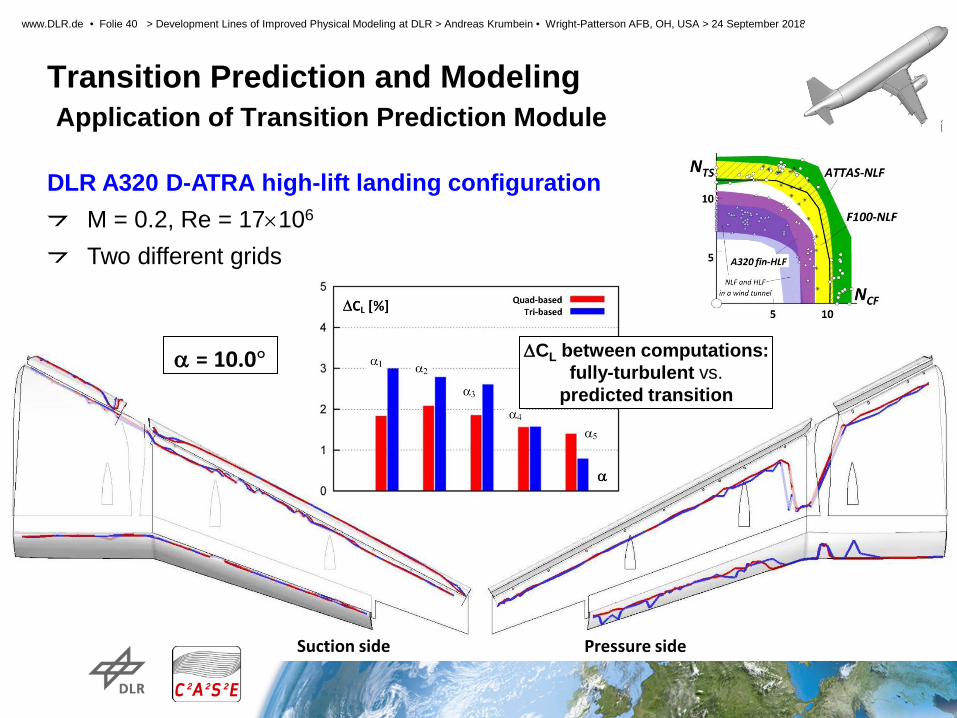
Transition Prediction and Modeling Application of Transition Prediction Module
DLR A320 D-ATRA high-lift landing configuration
M = 0.2, Re = 17×106 Two different grids
α = 10.0°
Suction side Pressure side
∆CL between computations: fully-turbulent vs.
predicted transition
STELAR 2. Projekttreffen > DLR Göttingen > 23.04.2012
Slide 41
www.DLR.de • Folie 41 > Development Lines of Improved Physical Modeling at DLR > Andreas Krumbein • Wright-Patterson AFB, OH, USA > 24 September 2018
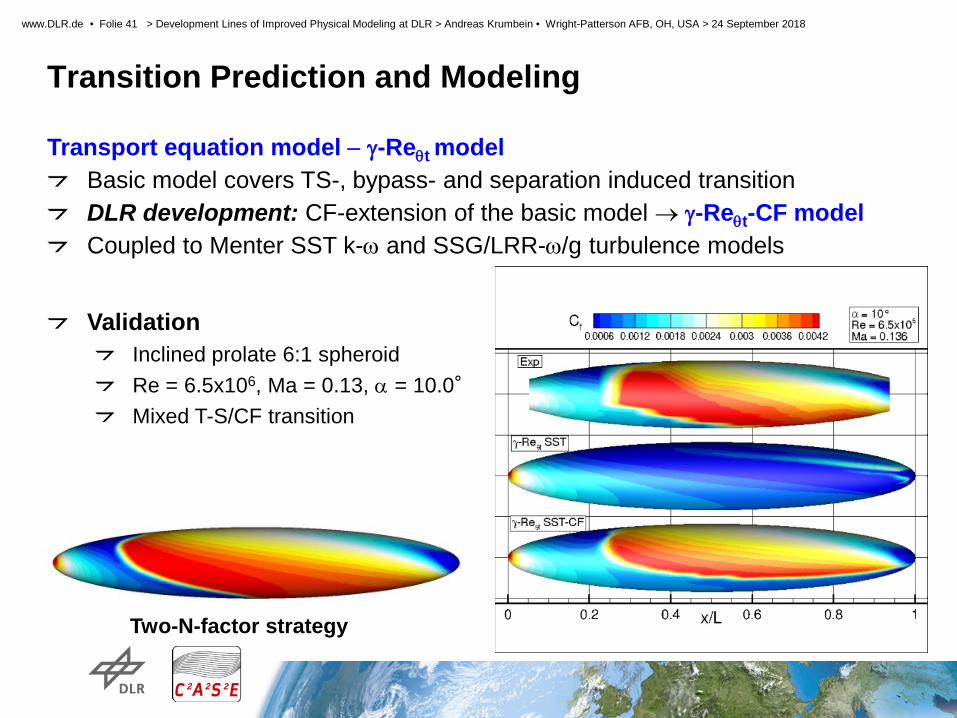
Transition Prediction and Modeling
Transport equation model − γ-Reθt model Basic model covers TS-, bypass- and separation induced transition DLR development: CF-extension of the basic model → γ-Reθt-CF model Coupled to Menter SST k-ω and SSG/LRR-ω/g turbulence models
Validation Inclined prolate 6:1 spheroid Re = 6.5x10⁶, Ma = 0.13, α = 10.0° Mixed T-S/CF transition
Two-N-factor strategy

STELAR 2. Projekttreffen > DLR Göttingen > 23.04.2012
Slide 42
www.DLR.de • Folie 42 > Development Lines of Improved Physical Modeling at DLR > Andreas Krumbein • Wright-Patterson AFB, OH, USA > 24 September 2018
Transition Prediction and Modeling Application of Transition Equation Model
Petzold & Radespiel
-x/l
-z/l
γ-Reθ-CF + RSM
γ-Reθ + RSM
TU Braunschweig Sickle Wing
Recm = 6.0 x 10⁶ CL = 0.4 (α = -1.58) M = 0.785
Rec= 2.75 x 10⁶ α = -2.6 M = 0.16
γ-Reθ-CF + RSM
DLR-F4 Wing-Body
γ-Reθ + RSM

STELAR 2. Projekttreffen > DLR Göttingen > 23.04.2012
Slide 43
www.DLR.de • Folie 43 > Development Lines of Improved Physical Modeling at DLR > Andreas Krumbein • Wright-Patterson AFB, OH, USA > 24 September 2018
Transition Prediction and Modeling Application of Transition Equation Model
Petzold & Radespiel
-x/l
-z/l
γ-Reθ-CF + RSM
γ-Reθ + RSM
TU Braunschweig Sickle Wing
Recm = 6.0 x 10⁶ CL = 0.4 (α = -1.58) M = 0.785
Rec= 2.75 x 10⁶ α = -2.6 M = 0.16
γ-Reθ-CF + RSM
DLR-F4 Wing-Body
γ-Reθ + RSM
Ongoing and future activities Getting rid of this malfunction Extension to rotating systems Hybrid laminar-flow control (HLFC) Coupling to hybrid RANS/LES methods

STELAR 2. Projekttreffen > DLR Göttingen > 23.04.2012
Slide 44
www.DLR.de • Folie 44 > Development Lines of Improved Physical Modeling at DLR > Andreas Krumbein • Wright-Patterson AFB, OH, USA > 24 September 2018
Turbulence modeling improvements
Challenge: Separated flow
Technology gap for moderate separation Maximum lift Shock induced separation
Need for better RANS turbulence models Today, simulation of moderately separated flows not reliable, neither with RANS, nor with hybrid RANS/LES methods (HRLM). RANS models needed for next decades
Due enormous computational costs for LES Pure RANS → highly complex configurations HRLM → components of aircraft or special configurations (fighter)
Technology gap must be closed Insignificant unsteadyness → RANS Significant unsteadyness → hybrid RANS/LES
Identification of significant physical phenomena necessary Flow separation, boundary-layer representation, shock/BL interaction Transition Wake modeling, vortical flows Engine jet flows, …
⇒ Dedicated RANS turbulence modeling improvements for specific flow phenomena
Chart: T. Knopp

STELAR 2. Projekttreffen > DLR Göttingen > 23.04.2012
Slide 45
www.DLR.de • Folie 45 > Development Lines of Improved Physical Modeling at DLR > Andreas Krumbein • Wright-Patterson AFB, OH, USA > 24 September 2018
Turbulence modeling improvements Change of current turbulence modeling paradigm
Focus not on validation of existing models using experiments Instead: use experiments to derive specific model modifications Twofold approach
Identify significant physical quantities and laws for specific identified phenomena Derive models satisfying identified laws
Design of experiments for phenomenon specific flows of major relevance
Dedicated physical experiments in wind tunnel Numerical experiments using LES/DNS
Finally, go back to traditional validation using more complex cases.
Large-scale overview measurement: 2D-2C PIV
VicToria experiment → toward flight Reθ = 35,000 in APG region
Instantaneous snapshot
Statistically averaged flow field
STELAR 2. Projekttreffen > DLR Göttingen > 23.04.2012
Slide 46
www.DLR.de • Folie 46 > Development Lines of Improved Physical Modeling at DLR > Andreas Krumbein • Wright-Patterson AFB, OH, USA > 24 September 2018
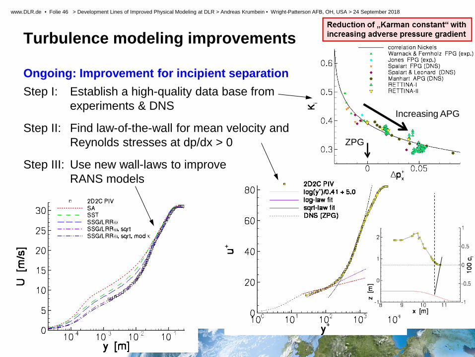
Turbulence modeling improvements Ongoing: Improvement for incipient separation Step I: Establish a high-quality data base from
experiments & DNS
Step II: Find law-of-the-wall for mean velocity and Reynolds stresses at dp/dx > 0
Step III: Use new wall-laws to improve RANS models
Increasing APG
ZPG

STELAR 2. Projekttreffen > DLR Göttingen > 23.04.2012
Slide 47
www.DLR.de • Folie 47 > Development Lines of Improved Physical Modeling at DLR > Andreas Krumbein • Wright-Patterson AFB, OH, USA > 24 September 2018
Turbulence modeling improvements Ongoing: Improvement for incipient separation Step I: Establish a high-quality data base from
experiments & DNS
Step II: Find law-of-the-wall for mean velocity and Reynolds stresses at dp/dx > 0
Step III: Use new wall-laws to improve RANS models
Increasing APG
ZPG
A very first step towards validation:
separation point from exp.
standard models new model
2D airfoil flow
α=12.00, Re=0.65×10⁶ M=0.07
HGR-01 airfoil (VTP)
STELAR 2. Projekttreffen > DLR Göttingen > 23.04.2012
Slide 48
www.DLR.de • Folie 48 > Development Lines of Improved Physical Modeling at DLR > Andreas Krumbein • Wright-Patterson AFB, OH, USA > 24 September 2018
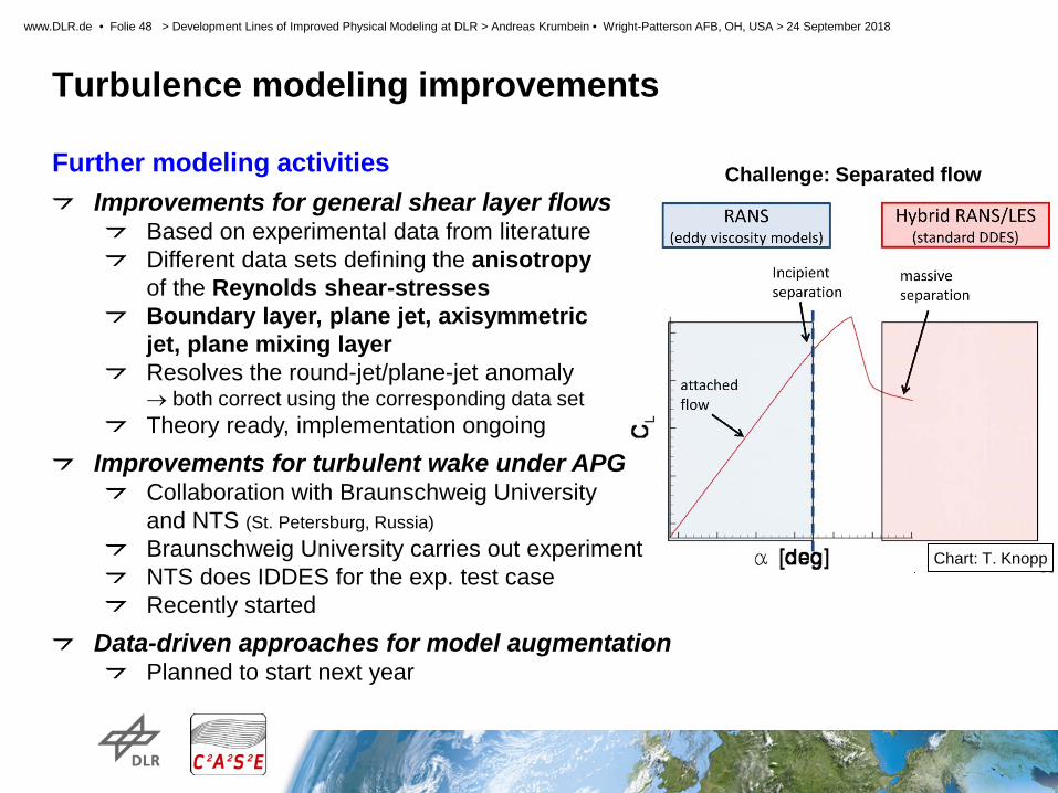
Turbulence modeling improvements Challenge: Separated flow Further modeling activities
Improvements for general shear layer flows Based on experimental data from literature Different data sets defining the anisotropy of the Reynolds shear-stresses Boundary layer, plane jet, axisymmetric jet, plane mixing layer Resolves the round-jet/plane-jet anomaly → both correct using the corresponding data set Theory ready, implementation ongoing
Improvements for turbulent wake under APG Collaboration with Braunschweig University and NTS (St. Petersburg, Russia) Braunschweig University carries out experiment NTS does IDDES for the exp. test case Recently started
Data-driven approaches for model augmentation Planned to start next year
Chart: T. Knopp

STELAR 2. Projekttreffen > DLR Göttingen > 23.04.2012
Slide 49
www.DLR.de • Folie 49 > Development Lines of Improved Physical Modeling at DLR > Andreas Krumbein • Wright-Patterson AFB, OH, USA > 24 September 2018
Turbulence modeling improvements Further modeling activities
Improvements for general shear layer flows Based on experimental data from literature Different data sets defining the anisotropy of the Reynolds shear-stresses Boundary layer, plane jet, axisymmetric jet, plane mixing layer Resolves the round-jet/plane-jet anomaly → both correct using the corresponding data set Theory ready, implementation ongoing
Improvements for turbulent wake under APG Collaboration with Braunschweig University and NTS (St. Petersburg, Russia) Braunschweig University carries out experiment NTS does IDDES for the exp. test case Recently started
Data-driven approaches for model augmentation Planned to start next year
Challenge: Separated flow
Chart: T. Knopp
STELAR 2. Projekttreffen > DLR Göttingen > 23.04.2012
Slide 50
www.DLR.de • Folie 50 > Development Lines of Improved Physical Modeling at DLR > Andreas Krumbein • Wright-Patterson AFB, OH, USA > 24 September 2018
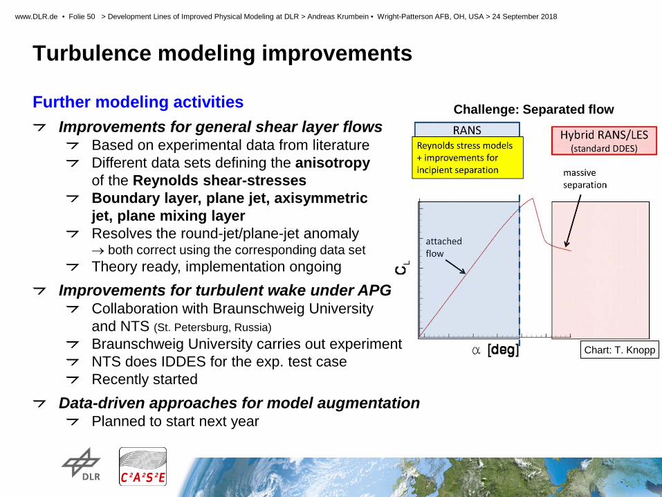
Turbulence modeling improvements Further modeling activities
Improvements for general shear layer flows Based on experimental data from literature Different data sets defining the anisotropy of the Reynolds shear-stresses Boundary layer, plane jet, axisymmetric jet, plane mixing layer Resolves the round-jet/plane-jet anomaly → both correct using the corresponding data set Theory ready, implementation ongoing
Improvements for turbulent wake under APG Collaboration with Braunschweig University and NTS (St. Petersburg, Russia) Braunschweig University carries out experiment NTS does IDDES for the exp. test case Recently started
Data-driven approaches for model augmentation Planned to start next year
Challenge: Separated flow
Chart: T. Knopp
STELAR 2. Projekttreffen > DLR Göttingen > 23.04.2012
Slide 51
www.DLR.de • Folie 51 > Development Lines of Improved Physical Modeling at DLR > Andreas Krumbein • Wright-Patterson AFB, OH, USA > 24 September 2018
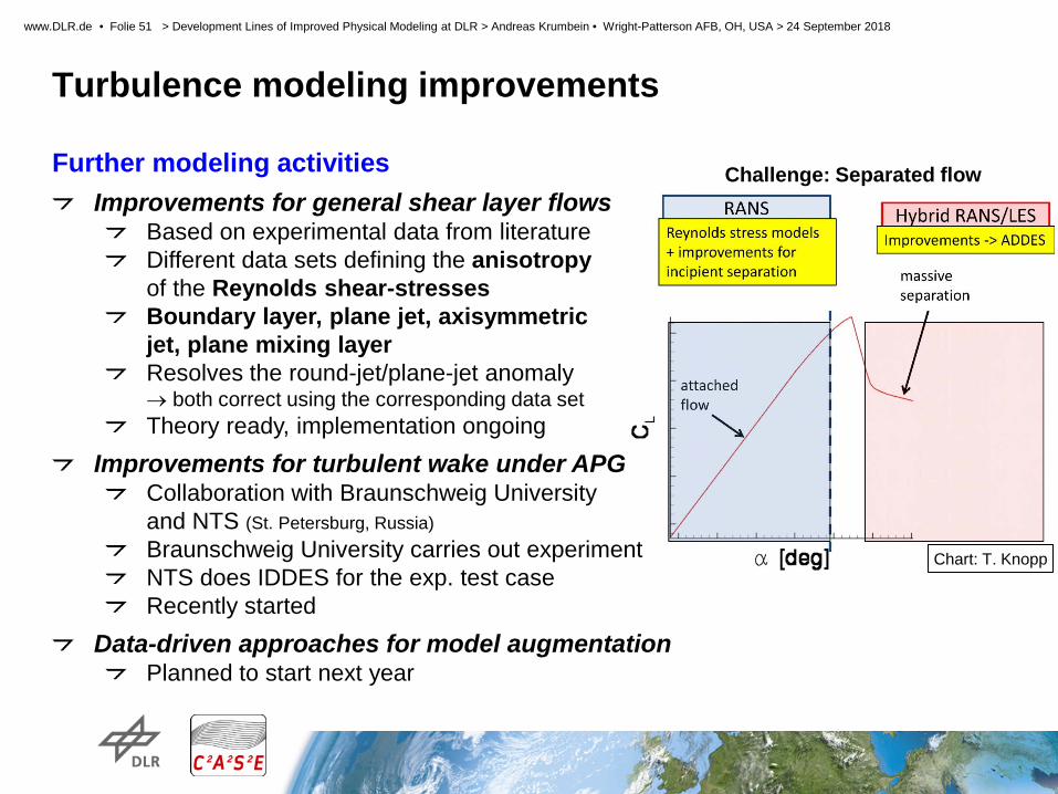
Turbulence modeling improvements Further modeling activities
Improvements for general shear layer flows Based on experimental data from literature Different data sets defining the anisotropy of the Reynolds shear-stresses Boundary layer, plane jet, axisymmetric jet, plane mixing layer Resolves the round-jet/plane-jet anomaly → both correct using the corresponding data set Theory ready, implementation ongoing
Improvements for turbulent wake under APG Collaboration with Braunschweig University and NTS (St. Petersburg, Russia) Braunschweig University carries out experiment NTS does IDDES for the exp. test case Recently started
Data-driven approaches for model augmentation Planned to start next year
Challenge: Separated flow
Chart: T. Knopp

STELAR 2. Projekttreffen > DLR Göttingen > 23.04.2012
Slide 52
www.DLR.de • Folie 52 > Development Lines of Improved Physical Modeling at DLR > Andreas Krumbein • Wright-Patterson AFB, OH, USA > 24 September 2018
Turbulence modeling improvements Further modeling activities
Improvements for general shear layer flows Based on experimental data from literature Different data sets defining the anisotropy of the Reynolds shear-stresses Boundary layer, plane jet, axisymmetric jet, plane mixing layer Resolves the round-jet/plane-jet anomaly → both correct using the corresponding data set Theory ready, implementation ongoing
Improvements for turbulent wake under APG Collaboration with Braunschweig University and NTS (St. Petersburg, Russia) Braunschweig University carries out experiment NTS does IDDES for the exp. test case Recently started
Data-driven approaches for model augmentation Planned to start next year
Challenge: Separated flow
Chart: T. Knopp

STELAR 2. Projekttreffen > DLR Göttingen > 23.04.2012
Slide 53
www.DLR.de • Folie 53 > Development Lines of Improved Physical Modeling at DLR > Andreas Krumbein • Wright-Patterson AFB, OH, USA > 24 September 2018
Turbulence modeling improvements Further modeling activities
Improvements for general shear layer flows Based on experimental data from literature Different data sets defining the anisotropy of the Reynolds shear-stresses Boundary layer, plane jet, axisymmetric jet, plane mixing layer Resolves the round-jet/plane-jet anomaly → both correct using the corresponding data set Theory ready, implementation ongoing
Improvements for turbulent wake under APG Collaboration with Braunschweig University and NTS (St. Petersburg, Russia) Braunschweig University carries out experiment NTS does IDDES for the exp. test case Recently started
Data-driven approaches for model augmentation Planned to start next year
Challenge: Separated flow
Chart: T. Knopp
All relevant physical phenomena


