
Development Guidelines & Improvement Standards · Development Guidelines & Improvement Standards...
147
Development Guidelines & Improvement Standards Version 2.0 Last Updated: 13 June 2018 (See Appendix 5 for revision history)
Transcript of Development Guidelines & Improvement Standards · Development Guidelines & Improvement Standards...

Development Guidelines &
Improvement Standards
Version 2.0
Last Updated: 13 June 2018
(See Appendix 5 for revision history)
i
Section 1. Introduction .................................................................................................................................. 1
1-1 Introduction ......................................................................................................................................... 1
1-2 Abbreviations ...................................................................................................................................... 2
1-3 Glossary of Terms ............................................................................................................................... 3
Section 2. Development Requirements ........................................................................................................ 6
2-1 Introduction ......................................................................................................................................... 6
2-2 Water Service ..................................................................................................................................... 6
2-3 Sewer Service ..................................................................................................................................... 6
2-4 Street Improvements ........................................................................................................................... 7
2-5 Other Permits, Fees ............................................................................................................................ 8
2-6 Easements .......................................................................................................................................... 9
Section 3. Public Facilities Construction ..................................................................................................... 10
3-1 Introduction ....................................................................................................................................... 10
3-2 Beginning the Process ...................................................................................................................... 10
3-3 Plan Check for Completeness .......................................................................................................... 10
3-4 Public Facilities Construction Agreement ......................................................................................... 11
3-5 Plan Review Process ........................................................................................................................ 11
3-6 Building Permit or Subdivision Approval ........................................................................................... 11
3-7 Project Acceptance ........................................................................................................................... 12
3-8 Latecomers Contracts ....................................................................................................................... 14
3-9 Turnaround Time .............................................................................................................................. 16
3-10 Flow Chart for Private Implementation of Public Improvements .................................................... 18
Section 4. Street Design Standards ............................................................................................................ 19
4-1 Introduction ....................................................................................................................................... 19
4-2 Street Classifications ........................................................................................................................ 19
4-3 Lane Widths ...................................................................................................................................... 20
4-4 Horizontal Street Alignment .............................................................................................................. 20
4-5 Vertical Street Alignment .................................................................................................................. 21
4-6 Intersections ...................................................................................................................................... 22
4-7 Roadway Transitions ........................................................................................................................ 22
4-8 Pavement Thickness ......................................................................................................................... 23
4-9 Guardrail Placement ......................................................................................................................... 23
4-10 Vertical Clearance ........................................................................................................................... 24
4-11 Lateral Clearance ............................................................................................................................ 24
4-12 Illumination and Drainage Design Standards ................................................................................. 24
4-13 Construction Specifications ............................................................................................................ 24
Section 5. Sanitary Sewer System .............................................................................................................. 47

ii
5-1 Introduction ....................................................................................................................................... 47
5-2 Criteria for Sewage Design ............................................................................................................... 47
Section 6. Water Distribution System ......................................................................................................... 55
6-1 Introduction ....................................................................................................................................... 55
6-2 Water Distribution System Design Requirements ............................................................................ 55
6-3 Construction of Water Main Extension ............................................................................................. 56
Section 7. Plan Preparation ........................................................................................................................ 64
7-1 General Requirements ...................................................................................................................... 64
7-2 Plan and Profile Sheets - Profile Layout ........................................................................................... 64
7-3 Plan and Profile Sheets - Plan Layout .............................................................................................. 64
Section 8. Illumination Plan Requirements And Design Criteria ................................................................. 66
8-1 When Streetlighting is Required ....................................................................................................... 66
8-2 Streetlighting Design Requirements ................................................................................................. 66
8-3 Collector and Residential Streets ..................................................................................................... 67
Section 9. Drainage ..................................................................................................................................... 68
9-1 Culvert Installation Guidelines and Specifications ............................................................................ 68
9-2 Floodplain Development ................................................................................................................... 71
Section 10. Local Improvement District Process ........................................................................................ 75
10-1 Introduction ..................................................................................................................................... 75
10-2 Procedure ....................................................................................................................................... 75
10-3 Steps ............................................................................................................................................... 75
Section 11. Traffic Studies .......................................................................................................................... 77
11-1 Responsibilities for Traffic Studies .................................................................................................. 77
11-2 Traffic Study Format ....................................................................................................................... 78
Section 12. Access And Site Access Design .............................................................................................. 87
12-1 Introduction ..................................................................................................................................... 87
12-2 Definitions ....................................................................................................................................... 87
12-3 Permit Required .............................................................................................................................. 87
12-4 Number of Driveways Permitted ..................................................................................................... 88
12-5 When Traffic Signals May Be Required .......................................................................................... 88
12-6 Driveway Spacing ........................................................................................................................... 88
12-7 Joint-Access Driveways .................................................................................................................. 88
12-8 Driveway Cuts on Existing Lots ...................................................................................................... 89
12-9 Corner Clearance ............................................................................................................................ 89
12-10 Regulation of Turns....................................................................................................................... 89
12-11 Standards For All Driveway Construction ..................................................................................... 89
12-12 Standards for Driveway Installation .............................................................................................. 90

iii
12-13 Sight Distance ............................................................................................................................... 90
12-14 Driveway Maintenance and Alignment ......................................................................................... 90
12-15 Arterial Access Denied Variances ................................................................................................ 90
12-16 Changes in Driveway Access When Arterial Improves ................................................................ 91
12-17 City Council Hearing on Driveway Improvements ........................................................................ 91
12-18 Duty of Owner of Parcel on Finalization of Driveway Improvement Plan ..................................... 91
12-19 Unsafe Driveway Traffic Study ..................................................................................................... 91
12-20 City Council Hearing on Unsafe Driveway .................................................................................... 91
12-21 Public Works Department to Inspect Improvements to Unsafe Driveway .................................... 92
12-22 Unused Driveways on Arterial Streets .......................................................................................... 92
12-23 Enforcement .................................................................................................................................. 92
12-24 Fees for Permits and Inspection ................................................................................................... 92
12-25 Prohibited Acts .............................................................................................................................. 92
12-26 Nuisances Declared - Abatement ................................................................................................. 93
12-27 Safe Access to Public Streets ....................................................................................................... 93
Section 13. Subdivisions ............................................................................................................................. 94
13-1 Introduction ..................................................................................................................................... 94
13-2 Definitions ....................................................................................................................................... 94
13-3 Lot Line Adjustments ...................................................................................................................... 96
13-4 Short Subdivisions .......................................................................................................................... 97
13-5 Preliminary Plats ........................................................................................................................... 101
13-6 Final Plat ....................................................................................................................................... 104
13-7 Site Plan for Land Divisions for Lease .......................................................................................... 106
13-8 General Improvement Standards .................................................................................................. 109
13-9 Cluster Subdivisions ..................................................................................................................... 113
13-10 Lots and Blocks ........................................................................................................................... 114
13-11 Parks, Open Space, and Public Areas ....................................................................................... 115
Section 14. Figures ................................................................................................................................... 117
Figure 4-1 Horizontal Stopping Sight Distance ..................................................................................... 117
Figure 4-2 Stopping Sight Distance for Crest Vertical Curves .............................................................. 118
Figure 4-3 Stopping Sight Distance for Sag Vertical Curves ................................................................ 119
Figure 4-4 Guard Rail Warrant Chart for Fill Section Embankments .................................................... 120
Figure 4-5 Recovery Area ..................................................................................................................... 121
Figure 5-1 Peaking Factor Versus Population ...................................................................................... 122
Figure 12-1 Driveway Width .................................................................................................................. 123
Figure 12-2 Distance from Intersections ............................................................................................... 124
Figure 12-3 Distance Between Driveways ............................................................................................ 125
iv
Appendices ............................................................................................................................................... 126
Appendix 1: Thresholds for requiring traffic studies .............................................................................. 126
Appendix 2: Traffic study requirements and study outline .................................................................... 128
Appendix 3: Level of service ranges for planning applications for signalized intersections ................. 129
Appendix 4: Traffic Study Requirements Form ..................................................................................... 130
Appendix 5: Document Revision History ............................................................................................... 131
Forms ........................................................................................................................................................ 132
Public Facilities Construction Application ............................................................................................. 132
Web Sites .................................................................................................................................................. 133
WSDOT Standards Website Link .......................................................................................................... 133
Standard Plans Table of Contents ............................................................................................................ 134
Section ST - 100 Streets ....................................................................................................................... 134
Section CG ‐ 200 Curbs, Gutters, and Sidewalk................................................................................... 134
Section TC ‐ 300 Traffic Channelization and Controls .......................................................................... 135
Section EL ‐ 400 Electrical, Lighting, and Signals ................................................................................ 135
Section DR ‐ 500 Drainage, Storm and Surface Water ........................................................................ 136
Section EC ‐ 600 Erosion Control ......................................................................................................... 136
Section SS ‐ 700 Sanitary Sewer .......................................................................................................... 136
Section WA ‐ 800 Water Distribution ..................................................................................................... 137
Section MS ‐ 1000 Miscellaneous Construction.................................................................................... 138
Standard Plans - Street ............................................................................................................................. 139
ST-100 Minimum Standard Alley Cross Section I ................................................................................. 139
ST-104 Minimum Stand Alley Cross Section II ..................................................................................... 140
ST-108 Minimum Standard A.C.C. Street Section ................................................................................ 141
ST-112 Minimum Standard Residential Concrete Street ...................................................................... 143
ST-116 Very Low Volume Minimum Residential Street (Lake Whatcom Watershed) .......................... 144
ST-120 Standard A.C.C. Section Residential Access Street ................................................................ 145
ST-124 Standard Residential Concrete Street...................................................................................... 146
ST-128 Very Low Volume Standard Residential Street (Lake Whatcom Watershed) .......................... 147
ST-132 Standard A.C.C. Section (Collector, Secondary, or Principal Arterial) .................................... 148
ST-150 Pocket Parking Detail ............................................................................................................... 149
ST-155 Bus Turnout Detail.................................................................................................................... 150
ST-157 Speed Hump Detail .................................................................................................................. 151
ST-160 70' Diameter Cul-De-Sac ......................................................................................................... 152
ST-165 Railroad Crossing Improvement ............................................................................................... 153
ST-170 Monument in Pavement New or Existing ................................................................................. 154
ST-171 Monument in Concrete (PCC) Street ....................................................................................... 155

v
ST-172 PVC Monument in Pavement for Overlay ................................................................................ 156
ST-173 Concrete Monument Outside Pavement .................................................................................. 157
ST-174 Core Monument in Pavement New or Existing ........................................................................ 158
ST-180 Horizontal Pavement Repair (Street Crossing) ........................................................................ 159
ST-182 Longitudinal Pavement Repair ................................................................................................. 160
ST-183 Adjusting Castings to Finish Grade .......................................................................................... 161
ST-184 Tree Planting Detail Planting Strip ........................................................................................... 162
ST-185 Tree Planting Detail Behind Sidewalk ...................................................................................... 163
Standard Plans - Curbs, Gutters and Sidewalks....................................................................................... 164
CG-200 Type "A" Modified Curb and Gutter ......................................................................................... 164
CG-202 Type "C" Traffic Curb ............................................................................................................... 165
CG-204 Rolled Curb and Gutter ........................................................................................................... 166
CG-208 Type "E" Barrier Curb .............................................................................................................. 167
CG-212 Extruded Cement Concrete Curb ............................................................................................ 168
CG-216 Extruded Asphalt Concrete Sections....................................................................................... 169
CG-218 Pavement Repair (Curb Replacement) ................................................................................... 170
CG-220 Gutter Treatment at Catch Basins ........................................................................................... 171
CG-230 Sidewalk .................................................................................................................................. 172
CG-232 City Center / Urban Village Sidewalk ...................................................................................... 173
CG-235 Porous Concrete Sidewalk ...................................................................................................... 174
CG-238 Parkway Sidewalk ................................................................................................................... 175
CG-242 Brick Paving Enlargement ....................................................................................................... 176
CG-246 Sidewalk Ramp Types 1A, 1B, 1C & 1D ................................................................................. 177
CG-260 Driveway Sections ................................................................................................................... 178
CG-265 Typical Driveway Examples .................................................................................................... 179
CG-270 Driveway Restoration .............................................................................................................. 180
Standard Plans - Traffic ............................................................................................................................ 181
TC-300 Abatement Sight Clearance Distances .................................................................................... 181
TC-305 Pavement Marking Details ....................................................................................................... 182
TC-310 Continental Crosswalk Detail ................................................................................................... 183
TC-315 Bicycle Lane Standards ........................................................................................................... 184
TC-316 Shared Lane Marking Standard ............................................................................................... 185
TC-317 Bicycle Detector Pavement Marking Standard ........................................................................ 186
TC-320 Street Sign Post Detail ............................................................................................................. 187
TC-325 Type 3 Barricade ...................................................................................................................... 188
TC-330 Flagger Control for Lane Closures ........................................................................................... 189
TC-340 Street Closure for Community Events ...................................................................................... 190
vi
Standard Plans - Electrical Lighting and Signals ...................................................................................... 191
EL-400 Residential Street Light and System Fusing ............................................................................ 191
EL-404 Arterial Street Signal & Luminaire Pole .................................................................................... 192
EL-408 Arterial Alternate Luminaire Pole .............................................................................................. 193
EL-420 Signal Head Mounting Detail .................................................................................................... 194
EL-424 Recessed Terminal Compartment ............................................................................................ 195
EL-428 Terminal Block .......................................................................................................................... 196
EL-432 Foundation Detail ..................................................................................................................... 197
EL-436 Type "P" Signal Cabinet Base Detail ........................................................................................ 198
EL-440 Type "K" Signal Cabinet Base Detail ........................................................................................ 199
EL-444 Contractor & Service Cabinet ................................................................................................... 200
EL-448 20 Conductor Signal Cable Detail ............................................................................................ 201
EL-452 Quazite Service Box ................................................................................................................. 202
EL-460 Type 1 Induction Loop .............................................................................................................. 203
EL-462 Type 2 Induction Loop .............................................................................................................. 204
EL-464 Bicycle Detector Pavement Marking Locations on Detector Loops ......................................... 205
Standard Plans - Drainage Storm and Surface Water .............................................................................. 206
DR-500 Thru-Curb Inlet Frame & Grate with Vertical Curb Installation ................................................ 206
DR-502 Herringbone Grate for Catch Basins & Inlets .......................................................................... 207
DR-505 Thru Curb Inlet Frame ............................................................................................................. 208
DR-510 Rolled Curb Frame & Grate ..................................................................................................... 209
DR-515 Type 60A and Type 60B Outlet Trap ....................................................................................... 210
DR-520 Cut Section Sidewalk Drain ..................................................................................................... 211
DR-525 Residential Sidewalk Drain ...................................................................................................... 212
DR-530 Storm Drain Side Service ........................................................................................................ 213
DR-538 PVC Pipe Bedding Details ....................................................................................................... 214
DR-539 Pipe Bedding Details for 2" or Less of Cover .......................................................................... 215
DR-540 Storm Pipe End Section .......................................................................................................... 216
DR-542 Restrictor Catch Basin Viewpoint Detail .................................................................................. 217
Standard Plans - Erosion Control ............................................................................................................. 218
EC-600 Temporary Construction Exit - Plat/Commercial ..................................................................... 218
EC-605 Temporary Construction Exit - Single Family .......................................................................... 219
EC-610 Tire Wash - Plat/Commercial ................................................................................................... 220
EC-612 Tire Wash Sump Details .......................................................................................................... 221
EC-615 Reinforced Silt Fence............................................................................................................... 222
EC-620 Catch Basin Insert.................................................................................................................... 223
EC-625 Temporary Sediment Pond (A) ................................................................................................ 224
vii
EC-630 Temporary Sedimentation Pond (B) ........................................................................................ 225
EC-635 Rock Check Dam ..................................................................................................................... 226
EC-640 Semi-Pervious Check Dam ...................................................................................................... 227
EC-645 Erosion Control Check Dam Detail .......................................................................................... 228
EC-650 Plastic Covering for Slopes and Stockpiles ............................................................................. 229
EC-655 Straw Rolls ............................................................................................................................... 230
Standard Plans - Sanitary Sewer .............................................................................................................. 231
SS-700 Manhole Standard .................................................................................................................... 231
SS-704 Standard Manhole Ring and Cover .......................................................................................... 232
SS-715 Inside Drop Sewer Manhole Connection ................................................................................. 233
SS-716 Ductile Iron Outside Drop Sewer Manhole Connection ........................................................... 234
SS-717 Concrete Enchased Outside Drop Sewer Manhole Connection .............................................. 235
SS-720 Sewer Main Cleanout ............................................................................................................... 236
SS-730 Sanitary Side Sewer................................................................................................................. 237
SS-735 Side Sewer Clean-Out Lid ....................................................................................................... 238
SS-740 Sanitary Banded Tapping Tee ................................................................................................. 239
SS-750 PVC Pipe Bedding Details ....................................................................................................... 240
SS-760 Pipe Anchor .............................................................................................................................. 241
SS-790 Typical Sewer Drawing of Record Including Services ............................................................. 242
Standard Plans - Water Distribution .......................................................................................................... 243
WA-802 Hydrant Installation ................................................................................................................. 243
WA-803 Sample Tap Installation .......................................................................................................... 244
WA-804 Fire Hydrant Protection Bollard Detail..................................................................................... 245
WA-810 Blow-Off for Future Water Main Extensions ........................................................................... 246
WA-814 2" Blow-Off for Future Water Main Extension ......................................................................... 247
WA-817 Typical Vacuum/Air Release Valve - Above Ground .............................................................. 248
WA-818 Typical Vacuum/Air Release Valve-Below Ground ................................................................. 249
WA-820 Water Pipe Bedding Details .................................................................................................... 250
WA-824 1" Single Water Service Detail ................................................................................................ 251
WA-826 Optional Dual Water Service Detail ........................................................................................ 252
WA-828 Typical Water Service on Private Property ............................................................................. 253
WA-830 1" Single Water Service in Meter Box ..................................................................................... 254
WA-834 Temporary Construction Water with Yard Hydrant ................................................................. 255
WA-836 Temporary Construction with Hose Bibb ................................................................................ 256
WA-840 1½" Meter Assembly ............................................................................................................... 257
WA-842 2" Meter Assembly .................................................................................................................. 258
WA-844 ⅝" to ¾" Meter Assembly ........................................................................................................ 259
viii
WA-846 Number 2 Meter Box ............................................................................................................... 260
WA-848 Number 2 Meter Box Modifications ......................................................................................... 261
WA-850 Number 3 Flat Top Meter Box ................................................................................................. 262
WA-858 Pressure Test Charge Manifold .............................................................................................. 263
WA-860 Thrust Block – Elbow .............................................................................................................. 264
WA-862 Thrust Block – Tee .................................................................................................................. 265
WA-865 Thrust Blocking for Cross with Valves .................................................................................... 266
WA-870 Existing Water Service Transfer Detail ................................................................................... 267
WA-872 Water Tap Excavation 4” and Larger ...................................................................................... 268
WA-874 Water Tap Excavation Under 4” .............................................................................................. 269
WA-882 Approved Restraints................................................................................................................ 271
WA-883 Fireline Restraints at Foundation ............................................................................................ 272
WA-884 Approved Restraints................................................................................................................ 273
WA-885 Fireline Restraints at Property Line ......................................................................................... 274
WA-890 3" 4" 6" 8" Meter Vault ............................................................................................................. 275
WA-897 Typical Water Main Drawing of Record, Including Services ................................................... 276
Standard Plans - Miscellaneous Construction .......................................................................................... 277
MS-1000 Rock Wall Details .................................................................................................................. 277
MS-1005 Low Retaining Walls .............................................................................................................. 278
MS-1010 Barrier Wall with Rail ............................................................................................................. 279
MS-1012 Barrier Wall with Rail ............................................................................................................. 280
MS-1014 Barrier Wall with Rail ............................................................................................................. 281
MS-1020 Pedestrian Handrail ............................................................................................................... 282
MS-1025 Barrier Rail ............................................................................................................................. 283
MS-1040 Bicycle Parking Standards .................................................................................................... 284
MS-1050 Mailbox Standards Plat/Commercial ..................................................................................... 285
MS-1060 Direct burial Meter Post Installation Detail ............................................................................ 286
1
Section 1. Introduction
1-1 Introduction
Implemented: 09/11/2001 Revised: 09/11/201
These development standards have been prepared to assist you in understanding the requirements of the
Public Works Department and to provide the basis for consistent design standards and policies. The
Public Works Department is responsible for the construction, operation and maintenance of public
facilities that include: transportation facilities, domestic water distribution systems, sanitary sewer
systems, and stormwater runoff quantity and quality management.
This manual addresses the standards for construction of streets, alleys, water systems, sanitary sewer
systems, stormwater facilities, erosion and sediment control and traffic management facilities. These
standards are to be incorporated in all designs and proposals for facilities that will be placed in the public
right-of-way and owned, operated, and maintained by the City of Bellingham.
Many of the standards, tables, graphs and diagrams contained herein are self-explanatory in their basic
presentation. The contents in this manual related to design should not, however, be perceived as a
"cookbook approach" to accomplishing engineering designs. The City of Bellingham requires that all
construction plans submitted for approval must be certified (stamped and signed) by a Professional
Engineer with a current registered license to practice civil engineering in the State of Washington.
Users of this manual should realize that compliance with the requirements and standards herein may not
fulfill all of the necessary requirements and conditions to pursue a development project. Applicants are
reminded that other city departments, as well as state and federal agencies, have requirements that must
be addressed to obtain a development permit. Other common requirements and conditions include, but
are not limited to, the following:
State Environmental Policy Act (SEPA)
Hydraulic Project Permit
Corps of Engineers (404 Permit)
Bellingham Comprehensive Plan
Bellingham Fill and Grade Permit
Shorelines Substantial Development Permit
Washington State Department of Transportation (WSDOT) Permit
Department of Ecology
The standards and policies presented in this manual are not intended to substitute for innovative or
creative efforts or good engineering judgment; however, any deviations from the standards and
procedures are subject to the approval of the Director of Public Works. Deviations should be submitted
only in the event that unique physical or environmental circumstances don't allow the standards to be
implemented.
Private utilities must also conform with the policies and standards of this manual as well as their franchise
agreements. The City will not allow the placement of communication cables, conductors, conduits or other
facilities within, over, or across the public right-of-way unless the applicant possesses the appropriate
franchise(s) with the City.

2
1-2 Abbreviations
Implemented: 09/11/2001 Revised: 01/01/1998
A.A.S.H.T.O. American Association of State Highway Transportation Officials
A.C. Asphalt Concrete
A.P.W.A. American Public Works Association
A.S.T.M. American Society of Testing Materials
A.T.B. Asphalt-Treated Base
A.W.W.A. American Water Works Association
B.C. Begin Curb
B.C.R. Begin Curb Return
C.F. Cubic Feet
C.M.P. Corrugated Metal Pipe
E.I.S. Environmental Impact Statement
F/L Flow Line
I.T.E. Institute of Transportation Engineers
L.F. Linear Feet
LID Local Improvement District
M.J. Mechanical Joint
M.U.T.C.D. Manual on Uniform Traffic Control Devices
P.C. Point of Curvature
P.C.C. Portland Cement Concrete
P.I. Point of Intersection
P.S.I. Pounds Per Square Inch
P.T. Point of Tangency
P.V.C. Poly Vinyl Chloride
R/W Right-of-Way
S.E.P.A. State Environmental Policy Act
S.F. Square Feet
T.S.M. Transportation System Management
V.C. Volume to Capacity
WSDOT Washington State Department of Transportation
3
1-3 Glossary of Terms
Implemented: 09/11/2001 Revised: 12/12/2014
Access: Driveway or other point of access such as a street, road, or highway that connects to the general
street system. Where two public streets intersect, the secondary street will be the access.
Approach: The portion of an intersection leg which is used by traffic approaching the intersection.
Arterial Street: Every public highway, or portion thereof, or major street designated as such by ordinance
in accordance with the law of the State of Washington.
Average Design Flow: Average monthly flow of the maximum month, estimated for the design year of
the sewage works.
Base Flood: The flood having a 1% chance of being equaled or exceeded in any given year.
Butterfly Valve: A valve wherein the disk, as it opens or closes, rotates about a spindle supported by the
frame of the valve. The valve is opened at a stem. At full opening, the disk is in a position parallel to the
axis of the conduit.
Capacity: The maximum number of vehicles that have reasonable expectation of passing over a given
roadway or section of roadway in one direction during a given time period under prevailing roadway and
traffic conditions.
Channelization: The separation or regulation of conflicting traffic movements into definite paths of travel
by the use of pavement markings, raised islands or other suitable means to facilitate the safe and orderly
movement of both vehicles and pedestrians.
Combined Sewer: A sewer intended to receive both wastewater and storm or surface water.
Commercial Driveway: A driveway providing access to an office, retail or institutional building, or to an
apartment building having 5 or more dwelling units.
Curb Return-Type Driveway: A driveway which is essentially a T intersection with constant curb cross
section from curb-return to curb-return as found at the intersection of two streets.
Delay: Stopped time per approach vehicle.
Depressed-Type Driveway: A driveway in which the curb is depressed along the curb line per City of
Bellingham Standard Plans drawing CG-260.
Driveway: A vehicle access between abutting property and a city right-of-way or a city street.
Driveway Width: The driveway throat distance, measured at the property line, for both depressed and
curb entry-type driveways. (See Figure 12-1)
Easement: An acquired legal right to the use of land owned by others.
Existing Street: Existing street means a present traveled way with a minimum width of 18 feet of hard
surfacing irrespective of whether it has been accepted by the City for maintenance. A hard-surfaced
street shall be a street consisting of either portland cement or asphalt concrete as a wearing surface.
Floodway: The channel of a river or other watercourse and the adjacent land areas that must be
reserved in order to discharge the base flood without cumulatively increasing the water surface elevation
more than one foot.
Floodway Fringe: The area in the floodplain excluding the floodway.
4
Flow Line: The position of the water surface in a flowing stream or conduit.
Gate Valve: A valve in which the closing element consists of a disk which slides over the opening or
cross-sectional area through which water passes and fits tightly against it.
Geometric Design: The arrangement of the visible elements of a street such as alignment, grade, sight
distance, widths and slopes.
Grade: Rate or percent of change in slope, either ascending or descending, from or along the street. It is
measured along the centerline of the street.
Hydrant: A device, connected to a water main and provided with the necessary valves and outlets, to
which a fire hose may be attached for discharging water at a high rate for the purpose of extinguishing
fires, washing down streets, or flushing out the water main. Also called a fireplug.
Industrial Driveway: A driveway directly serving substantial numbers of truck movements to and from
loading docks of an industrial facility, warehouse, truck terminal, or community or regional mall loading
area.
Industrial Wastes: Liquid or other wastes resulting from any process of industry, manufacture, trade,
business, or from the development of any natural resources.
Infiltration: Groundwater that enters the sewer system through sewer joints, cracks, service connections
and other sources.
Inflow: Surface water that enters the sewer system through storm drains, roof drains, manhole covers,
and other sources.
LID Commitment: An agreement to support a local improvement district to bring the abutting streets to
the standards specified in Section 4, such agreement to be a covenant running with the land.
Minimum-Standard Street: A street constructed to line and grade having not less than 20’ of paved
width with 4’ shoulders and adequate provision for storm drainage.
Minor Street: Any city street not designated by competent authority as an arterial street, a state highway,
a parkway, an expressway or a freeway.
Monument: An object used to permanently mark a surveyed location. The size, shape and design of the
monument is to be in accordance with standards specified by the Washington State Department of
Natural Resources as authorized by RCW 58.17 and City of Bellingham Standard Plan ST-170, ST-171,
ST-172, ST-173, ST-174.
Parcel: Any piece of real property in a single ownership.
Public Works Department: The Department of Public Works of the City of Bellingham.
Queue: A line of vehicles waiting to perform a movement.
Residential Driveway: A driveway providing access to a single-family residence, duplex, or an apartment
building containing not more than 4 dwellings.
Right-of-Way: A right of passage over another person’s land.
R-Value: A method of evaluating treated and untreated materials for bases, sub-bases, and subgrades
for pavement thickness design.
Sewage: The water-carried human wastes from residences, buildings, industrial establishments, or other
places together with such industrial wastes or underground, surface, storm, or other water, as may be
present.
5
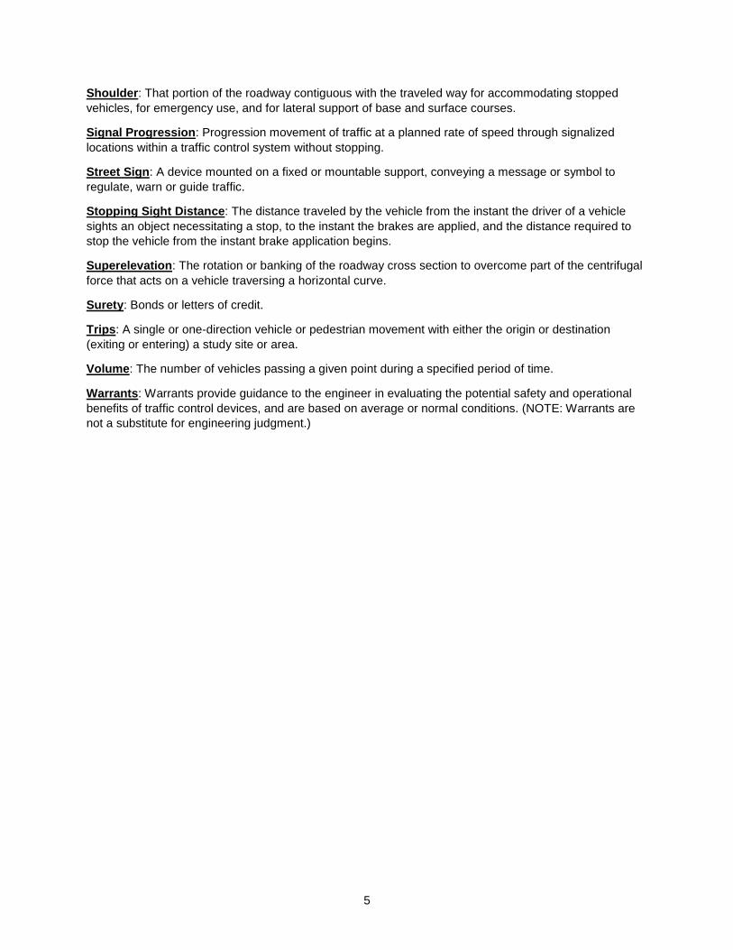
Shoulder: That portion of the roadway contiguous with the traveled way for accommodating stopped
vehicles, for emergency use, and for lateral support of base and surface courses.
Signal Progression: Progression movement of traffic at a planned rate of speed through signalized
locations within a traffic control system without stopping.
Street Sign: A device mounted on a fixed or mountable support, conveying a message or symbol to
regulate, warn or guide traffic.
Stopping Sight Distance: The distance traveled by the vehicle from the instant the driver of a vehicle
sights an object necessitating a stop, to the instant the brakes are applied, and the distance required to
stop the vehicle from the instant brake application begins.
Superelevation: The rotation or banking of the roadway cross section to overcome part of the centrifugal
force that acts on a vehicle traversing a horizontal curve.
Surety: Bonds or letters of credit.
Trips: A single or one-direction vehicle or pedestrian movement with either the origin or destination
(exiting or entering) a study site or area.
Volume: The number of vehicles passing a given point during a specified period of time.
Warrants: Warrants provide guidance to the engineer in evaluating the potential safety and operational
benefits of traffic control devices, and are based on average or normal conditions. (NOTE: Warrants are
not a substitute for engineering judgment.)
6
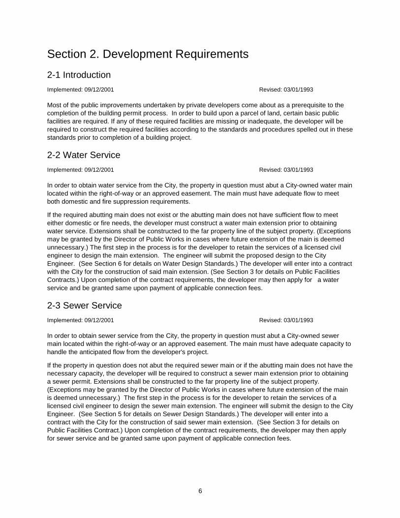
Section 2. Development Requirements
2-1 Introduction
Implemented: 09/12/2001 Revised: 03/01/1993
Most of the public improvements undertaken by private developers come about as a prerequisite to the
completion of the building permit process. In order to build upon a parcel of land, certain basic public
facilities are required. If any of these required facilities are missing or inadequate, the developer will be
required to construct the required facilities according to the standards and procedures spelled out in these
standards prior to completion of a building project.
2-2 Water Service
Implemented: 09/12/2001 Revised: 03/01/1993
In order to obtain water service from the City, the property in question must abut a City-owned water main
located within the right-of-way or an approved easement. The main must have adequate flow to meet
both domestic and fire suppression requirements.
If the required abutting main does not exist or the abutting main does not have sufficient flow to meet
either domestic or fire needs, the developer must construct a water main extension prior to obtaining
water service. Extensions shall be constructed to the far property line of the subject property. (Exceptions
may be granted by the Director of Public Works in cases where future extension of the main is deemed
unnecessary.) The first step in the process is for the developer to retain the services of a licensed civil
engineer to design the main extension. The engineer will submit the proposed design to the City
Engineer. (See Section 6 for details on Water Design Standards.) The developer will enter into a contract
with the City for the construction of said main extension. (See Section 3 for details on Public Facilities
Contracts.) Upon completion of the contract requirements, the developer may then apply for a water
service and be granted same upon payment of applicable connection fees.
2-3 Sewer Service
Implemented: 09/12/2001 Revised: 03/01/1993
In order to obtain sewer service from the City, the property in question must abut a City-owned sewer
main located within the right-of-way or an approved easement. The main must have adequate capacity to
handle the anticipated flow from the developer's project.
If the property in question does not abut the required sewer main or if the abutting main does not have the
necessary capacity, the developer will be required to construct a sewer main extension prior to obtaining
a sewer permit. Extensions shall be constructed to the far property line of the subject property.
(Exceptions may be granted by the Director of Public Works in cases where future extension of the main
is deemed unnecessary.) The first step in the process is for the developer to retain the services of a
licensed civil engineer to design the sewer main extension. The engineer will submit the design to the City
Engineer. (See Section 5 for details on Sewer Design Standards.) The developer will enter into a
contract with the City for the construction of said sewer main extension. (See Section 3 for details on
Public Facilities Contract.) Upon completion of the contract requirements, the developer may then apply
for sewer service and be granted same upon payment of applicable connection fees.
7
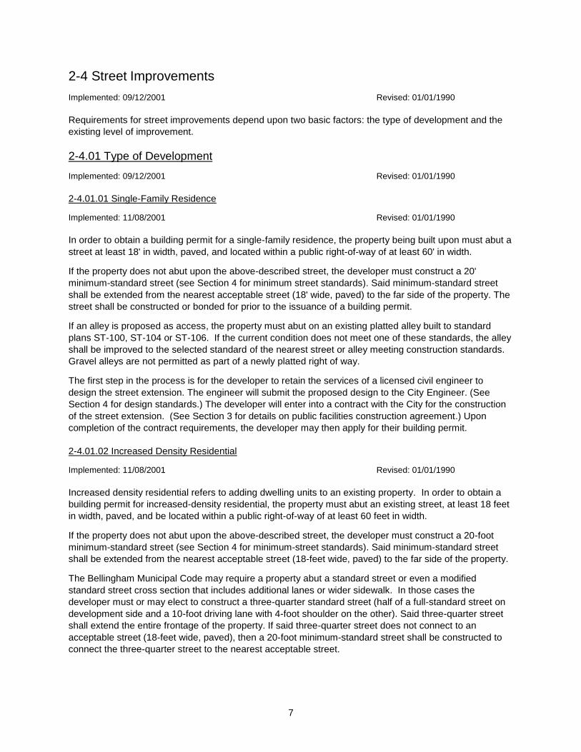
2-4 Street Improvements
Implemented: 09/12/2001 Revised: 01/01/1990
Requirements for street improvements depend upon two basic factors: the type of development and the
existing level of improvement.
2-4.01 Type of Development
Implemented: 09/12/2001 Revised: 01/01/1990
2-4.01.01 Single-Family Residence
Implemented: 11/08/2001 Revised: 01/01/1990
In order to obtain a building permit for a single-family residence, the property being built upon must abut a
street at least 18' in width, paved, and located within a public right-of-way of at least 60' in width.
If the property does not abut upon the above-described street, the developer must construct a 20'
minimum-standard street (see Section 4 for minimum street standards). Said minimum-standard street
shall be extended from the nearest acceptable street (18' wide, paved) to the far side of the property. The
street shall be constructed or bonded for prior to the issuance of a building permit.
If an alley is proposed as access, the property must abut on an existing platted alley built to standard
plans ST-100, ST-104 or ST-106. If the current condition does not meet one of these standards, the alley
shall be improved to the selected standard of the nearest street or alley meeting construction standards.
Gravel alleys are not permitted as part of a newly platted right of way.
The first step in the process is for the developer to retain the services of a licensed civil engineer to
design the street extension. The engineer will submit the proposed design to the City Engineer. (See
Section 4 for design standards.) The developer will enter into a contract with the City for the construction
of the street extension. (See Section 3 for details on public facilities construction agreement.) Upon
completion of the contract requirements, the developer may then apply for their building permit.
2-4.01.02 Increased Density Residential
Implemented: 11/08/2001 Revised: 01/01/1990
Increased density residential refers to adding dwelling units to an existing property. In order to obtain a
building permit for increased-density residential, the property must abut an existing street, at least 18 feet
in width, paved, and be located within a public right-of-way of at least 60 feet in width.
If the property does not abut upon the above-described street, the developer must construct a 20-foot
minimum-standard street (see Section 4 for minimum-street standards). Said minimum-standard street
shall be extended from the nearest acceptable street (18-feet wide, paved) to the far side of the property.
The Bellingham Municipal Code may require a property abut a standard street or even a modified
standard street cross section that includes additional lanes or wider sidewalk. In those cases the
developer must or may elect to construct a three-quarter standard street (half of a full-standard street on
development side and a 10-foot driving lane with 4-foot shoulder on the other). Said three-quarter street
shall extend the entire frontage of the property. If said three-quarter street does not connect to an
acceptable street (18-feet wide, paved), then a 20-foot minimum-standard street shall be constructed to
connect the three-quarter street to the nearest acceptable street.
8
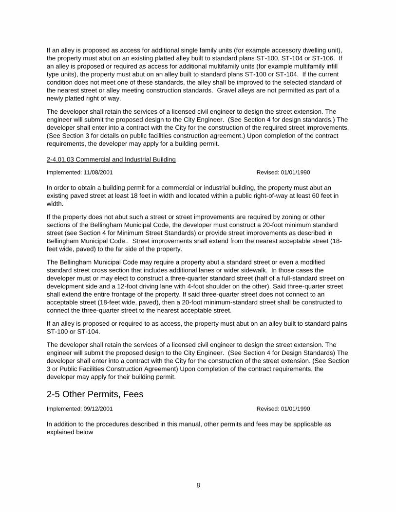
If an alley is proposed as access for additional single family units (for example accessory dwelling unit),
the property must abut on an existing platted alley built to standard plans ST-100, ST-104 or ST-106. If
an alley is proposed or required as access for additional multifamily units (for example multifamily infill
type units), the property must abut on an alley built to standard plans ST-100 or ST-104. If the current
condition does not meet one of these standards, the alley shall be improved to the selected standard of
the nearest street or alley meeting construction standards. Gravel alleys are not permitted as part of a
newly platted right of way.
The developer shall retain the services of a licensed civil engineer to design the street extension. The
engineer will submit the proposed design to the City Engineer. (See Section 4 for design standards.) The
developer shall enter into a contract with the City for the construction of the required street improvements.
(See Section 3 for details on public facilities construction agreement.) Upon completion of the contract
requirements, the developer may apply for a building permit.
2-4.01.03 Commercial and Industrial Building
Implemented: 11/08/2001 Revised: 01/01/1990
In order to obtain a building permit for a commercial or industrial building, the property must abut an
existing paved street at least 18 feet in width and located within a public right-of-way at least 60 feet in
width.
If the property does not abut such a street or street improvements are required by zoning or other
sections of the Bellingham Municipal Code, the developer must construct a 20-foot minimum standard
street (see Section 4 for Minimum Street Standards) or provide street improvements as described in
Bellingham Municipal Code.. Street improvements shall extend from the nearest acceptable street (18-
feet wide, paved) to the far side of the property.
The Bellingham Municipal Code may require a property abut a standard street or even a modified
standard street cross section that includes additional lanes or wider sidewalk. In those cases the
developer must or may elect to construct a three-quarter standard street (half of a full-standard street on
development side and a 12-foot driving lane with 4-foot shoulder on the other). Said three-quarter street
shall extend the entire frontage of the property. If said three-quarter street does not connect to an
acceptable street (18-feet wide, paved), then a 20-foot minimum-standard street shall be constructed to
connect the three-quarter street to the nearest acceptable street.
If an alley is proposed or required to as access, the property must abut on an alley built to standard palns
ST-100 or ST-104.
The developer shall retain the services of a licensed civil engineer to design the street extension. The
engineer will submit the proposed design to the City Engineer. (See Section 4 for Design Standards) The
developer shall enter into a contract with the City for the construction of the street extension. (See Section
3 or Public Facilities Construction Agreement) Upon completion of the contract requirements, the
developer may apply for their building permit.
2-5 Other Permits, Fees
Implemented: 09/12/2001 Revised: 01/01/1990
In addition to the procedures described in this manual, other permits and fees may be applicable as
explained below
9
2-5.01 Street Obstruction Permit
Implemented: 09/12/2001 Revised: 01/01/1990
A street obstruction permit is required for any construction within the public right-of-way. A permit is not
required for work performed under contract with the City. This includes, but is not limited to, driveways,
sidewalks, sewer or water services, trenches, utility excavations, fences, foundations or other structures.
Permits are obtained along with building permits. The person or company undertaking the work shall be
covered by a $5,000.00 street obstruction bond acceptable to the City. In lieu of the bond for a one-time-
only job, a cash deposit in the amount of 150% of the estimated cost of the work shall be deposited with
the City Finance Director. The deposit will be returned upon acceptance of the work.
2-5.02 Water/Sewer Permit
Implemented: 09/12/2001 Revised: 08/01/95
Water/sewer permits are required to connect to the City's water or sewer system. Permits are obtained
along with building permits upon payment of applicable connection fees. All permitted construction must
be inspected by the Public Works Department's Engineering Division.
2-6 Easements
Implemented: 09/12/2001 Revised: 06/01/97
Public utilities shall be located within the public right-of-way unless field conditions make this impractical.
In the event that a public utility must be placed on private property, a maintenance easement 20 feet wide
and centered over the utility shall be granted to the City. Where more than one public utility is to be
placed in the easement, the utilities must be separated by 10 feet with a 10-foot buffer to the outside of
the easement. In other words, two utilities would require a 30-foot easement width, three utilities would
require 40 feet, etc.

10
Section 3. Public Facilities Construction
3-1 Introduction
Implemented: 09/12/2001 Revised: 01/01/1998
The following chapter has been developed to assist an owner, developer, or engineer with the Bellingham
Public Works Department's requirements for all improvements being contemplated within City right-of-
way. Improvements to public rights-of-way are normally required of an owner or developer as a condition
to receiving a building permit or as a condition to subdividing property.
Early in the plan review process, the owner will be asked to sign a Public Facilities Construction
Agreement which will bind the owner to the project description, the project schedule, required fees and
deposits, bond requirements, and other related items.
3-2 Beginning the Process
Implemented: 09/12/2001 Revised: 01/01/1998
The process begins with submittal of an engineering plan and Public Facilities Agreement to the City
Engineer along with a Letter of Intent containing the following:
1. Identification of the property owner.
2. Type of ownership: Corporation, Partnership, Sole Proprietor, or Joint Venture.
3. Name and title of owner's officer with authority to sign.
4. Address of owner.
5. Complete description of the project to be constructed and conveyed to the City.
6. The approximate construction schedule.
7. An estimate of the project cost.
8. The type of financial security the owner intends to use: a standard surety bond, an
assignment of funds, cash deposit, or letter of credit.
Upon receipt of the above, the City Engineer will assign a project engineer to act as the project manager
on behalf of the City for the purpose of carrying out the terms of the Public Facilities Construction
Agreement.
3-3 Plan Check for Completeness
Implemented: 09/12/2001 Revised: 01/01/1998
Upon receipt of a construction plan package, the project manager will check for completeness of the plan
using the following guide:
1. Are the drawings signed by a Civil Engineer?
2. Are the plan and profile drawings complete? (See Section 7)
3. Are drainage calculations included? (See Section 9) Do the plans include provisions for
erosion control?
4. Does the Letter of Intent contain sufficient information?
11
If the plan package is determined to be incomplete, the project manager will notify the applicant of any
additional materials or information needed for the process to continue. Upon receipt of the needed
information, the project manager will request three copies of the plan and will have the Public Facilities
Construction Agreement prepared.
3-4 Public Facilities Construction Agreement
Implemented: 09/12/2001 Revised: 01/01/1998
The project manager will use the information supplied in the Letter of Intent to create a document
package, which will contain the following:
1. Public Facilities Permit Application
2. Surety Bond
3. Public Works Project Permit
4. Deed of Conveyance of Public Improvements
As soon as available, the project manager will send the applicant a copy of the agreement and the surety
bond form for signature. The plans and specifications will not be reviewed by the project manager until
he/she receives the signed agreement, the surety bond, and payment of all fees and deposits listed in the
agreement. Fees and deposits normally required are as follows:
1. Administration Deposit (percent of estimated cost)
2. Water Connection Deposit (estimated cost by Water Division)
3. Sanitary Sewer Scan Fee ($0.50 per linear foot)
4. Storm Water Permit Fee
5. Hydrant Fund Fee ($3 per linear foot)
3-5 Plan Review Process
Implemented: 09/12/2001 Revised: 01/01/1998
As soon as the project manager receives three copies of the plans, he/she will send one copy to the
Operations Division and one copy to the Engineering Division for review by Staff. The third copy will be
retained by the project manager for reference and for his/her future review.
Upon receipt of the signed agreement, the financial security, and payment of all fees and deposits, the
project manager will carefully review the plans and specifications. Comments will be sent to the applicant
regarding the corrections, additions, or deletions that should be made to the plans and specifications
before approval can be granted. After final corrections are made to the plans and specifications, the
originals shall be delivered to the project manager who will procure the signature of the City Engineer,
thereby, approving the plans and specifications.
When the applicant is prepared to begin construction, he/she shall notify the project manager and request
that a preconstruction conference be scheduled. The Public Works project permit will be presented to the
applicant following the preconstruction conference authorizing the construction to begin.
3-6 Building Permit or Subdivision Approval
Implemented: 09/12/2001 Revised: 01/01/1998
12
Plans and specifications approval for improvements within the City right-of-way or within a City easement
is one of many review processes one must pursue before receiving a building permit or plat approval. The
specific requirements for these are described in Section 2 of this manual.
City departments other than Public Works also will be involved in the review process for building permit or
subdivision approval. They are as follows:
1. Planning and Economic Development Department
2. Building Services Division
3. Fire Department (Fire Marshal)
The applicant should contact each City department to discuss specific requirements prior to finalizing
plans and specifications. The project manager should be contacted as soon as possible if a plan change
becomes imminent.
3-7 Project Acceptance
Implemented: 09/12/2001 Revised: 01/27/2006
Upon completion of the construction work, the applicant will notify the project manager and request an
inspection. The project manager will schedule the inspection, then provide the applicant with a list of
deficiencies (punch list) which must be corrected within 30 calendar days. Upon completion of the punch
list, the applicant will again notify the project manager who will then schedule a final inspection.
After all deficiencies have been corrected, the applicant will be asked to provide the following:
1. Certified "as-built" mylars.
2. Certified statement of the full cost of the project using Public Works Cost Statement.
3. A copy of all required easements which have been recorded at the County Courthouse.
4. The Deed of Conveyance for all project improvements which are to be accepted by the City
for maintenance.
Upon receipt of all the above, the project manager will accept the project on behalf of the City and
authorize the reduction of the financial security to 25% of the actual project cost to protect the City against
defects in materials and workmanship in the project for one year.
Prior to one year following project acceptance, the City will conduct an end of maintenance period
inspection and develop a list of deficiencies. The applicant will be given 30 days to correct the
deficiencies. After all deficiencies are corrected, the financial security will be released.
3-7.01 RECORD DRAWING POLICY
The following is intended to provide necessary guidelines for development of required construction record
drawings:
1. Certified record drawings are to be provided by the owner and shall accurately reflect all field
revisions made during the construction process. Record drawings shall be submitted on the
same number of sheets as the original approved drawings.
2. The owner shall retain a licensed professional engineer to track all relevant field changes to
the approved construction drawings. Changes shall be clearly identified in a comprehensive
manner on one set of City-approved Xerox black-line,
13
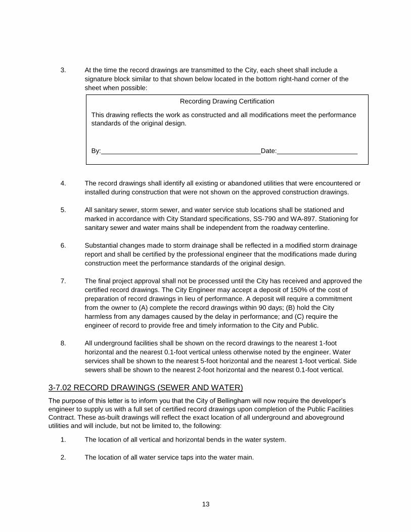
3. At the time the record drawings are transmitted to the City, each sheet shall include a
signature block similar to that shown below located in the bottom right-hand corner of the
sheet when possible:
4. The record drawings shall identify all existing or abandoned utilities that were encountered or
installed during construction that were not shown on the approved construction drawings.
5. All sanitary sewer, storm sewer, and water service stub locations shall be stationed and
marked in accordance with City Standard specifications, SS-790 and WA-897. Stationing for
sanitary sewer and water mains shall be independent from the roadway centerline.
6. Substantial changes made to storm drainage shall be reflected in a modified storm drainage
report and shall be certified by the professional engineer that the modifications made during
construction meet the performance standards of the original design.
7. The final project approval shall not be processed until the City has received and approved the
certified record drawings. The City Engineer may accept a deposit of 150% of the cost of
preparation of record drawings in lieu of performance. A deposit will require a commitment
from the owner to (A) complete the record drawings within 90 days; (B) hold the City
harmless from any damages caused by the delay in performance; and (C) require the
engineer of record to provide free and timely information to the City and Public.
8. All underground facilities shall be shown on the record drawings to the nearest 1-foot
horizontal and the nearest 0.1-foot vertical unless otherwise noted by the engineer. Water
services shall be shown to the nearest 5-foot horizontal and the nearest 1-foot vertical. Side
sewers shall be shown to the nearest 2-foot horizontal and the nearest 0.1-foot vertical.
3-7.02 RECORD DRAWINGS (SEWER AND WATER)
The purpose of this letter is to inform you that the City of Bellingham will now require the developer’s
engineer to supply us with a full set of certified record drawings upon completion of the Public Facilities
Contract. These as-built drawings will reflect the exact location of all underground and aboveground
utilities and will include, but not be limited to, the following:
1. The location of all vertical and horizontal bends in the water system.
2. The location of all water service taps into the water main.
Recording Drawing Certification
This drawing reflects the work as constructed and all modifications meet the performance
standards of the original design.
By: Date:
14
3. The location of all water service boxes and meters with distances to the main tap and to the
corresponding property corners.
4. The locations of all water valves, hydrants, hydrant valves, and blow-offs as to distance from
the centerline and distances to the nearest property lines or property corners.
5. The location of all utilities within easements. This will include distances to the utilities from the
easement lines.
6. The location of all side sewer tees into the sewer main from the back-station manhole.
7. The location of all side sewer ends according to the attached drawings and with the additional
stipulations:
a. The ends must be tied out to the corresponding property corners.
b. The depth of the end at the location board must be noted.
8. The location of all sanitary manholes, storm sewer manholes, storm sewer catch basins and
back-of-walk drains. These locations must include distances from the centerline monuments,
easement lines, or property corners.
9. All easements will be staked in advance of utility installations to ensure that the utilities fall
within the proper boundaries. Construction offset staking will not fulfill this requirement.
3-8 Latecomers Contracts
Implemented: 08/26/2004 Revised: 02/01/2004
Under the authority of the Bellingham Municipal Code (Ch. 14.02) property owners who construct public
improvements may be partially reimbursed by benefiting owners if a contract, facilitated by the City of
Bellingham, with other property owners is implemented. Public improvements include streets, water
mains, sanitary sewer mains, and storm water facilities. Entering into a "Latecomer Contract" requires a
timely request by the project proponent and procedures that must be followed by both the proponent and
the City as described below.
3-8.01 Procedures To Be Followed By The Proponent:
1. Prior to the time the project is accepted by the City, the proponent must notify the City of the
intent to seek a Latecomer Contract. Notification consists of a letter stating the intention along
with a list and map of the property owners who the proponent believes will benefit from the
improvement(s). Signature of the “Acknowledgement of Understanding” letter provided to
developers with the deed of conveyance information can satisfy this requirement.
2. Once the City receives the request, a pre-application meeting will be scheduled and the
proponent will have the opportunity to present the proposal to City staff. This meeting will
consist of discussion of the proposal, comments and suggestions from the City, and general
preparation for submittal of the formal application.
15
3. Within 30 days of street and/or utility system improvements being deeded to the city (Deed of
Conveyance), the proponent may request a Latecomer Contract by making a formal
application. Application shall be made on forms prepared by the Public Works Department
and shall be accompanied by the base fee portion of the City Administrative Fees as set forth
in BMC 14.02.130. The application shall be prepared and/or approved by a professional
licensed engineer and shall contain the following information:
a. A legal description of the applicant's property.
b. A legal description of the properties within the applicant's proposed assessment
reimbursement area together with the names and addresses of the owners of each
property as shown in the records of the Assessor's Office of Whatcom County.
c. Vicinity map of applicant's property, proposed reimbursement area, and location of all
improvements.
d. Itemized cost data for cost of construction certified by a Professional Engineer.
e. Cost of construction = direct construction costs + developer administrative costs +
construction interest + city latecomer administrative fee. (See Bellingham Municipal
Code 14.02 for eligible costs and calculation details.)
f. The applicant's proposed allocation of cost of construction to the individual properties
within the applicant's proposed assessment reimbursement area and the method of
such allocation.
g. Payment of the base fee portion of the City Administrative Fee, which shall be non-
refundable. Fee shall be calculated as follows:
h. Base Fee ($400 for utility project and $590 for street project) + 1% of direct
construction cost + $200 for every separate parcel of property within the applicant's
proposed assessment reimbursement area. Fees are adjusted annually in
accordance with BMC 14.02.130(C) and should be confirmed prior to submitting a
latecomers application.
4. Within 30 days of the Public Works Department receiving the application for a Developer
Reimbursement Agreement, the Public Works Department will provide the applicant written
notice of whether the application is complete and, if incomplete, what must be done for the
application to be considered complete. The applicant will have no more than 30 days from the
date of the written notice to respond and provide the information required to complete the
application or, if the applicant cannot submit the required information within the 30-day
period, the applicant shall provide the City with a written explanation of why they cannot
provide the information within the designated time period and a date that the requested
information will be submitted. In its discretion, the Public Works Department may grant the
applicant an extension of not more than 60 days to submit the required information.
5. Sign and return the Application Summary (to be prepared by City Staff) for recording by Staff
with the County Auditor’s Office.
6. In the event a hearing is requested by a person owning property within the proposed
reimbursement area, the proponent must attend or send a representative to attend the
hearing.
7. Sign and return Latecomer Contract to the City.
16
3-8.02 Procedures to Be Followed By The City:
1. Schedule and conduct pre-application meeting. Make recommendations to applicant for
determination of assessment method and area for property benefited by the improvement(s).
2. Review application costs and confirm the potential benefit to properties within the proposed
assessment area. Confirm that the method used to calculate the allocation of assessment is
equitable and reasonable. If agreement between the developer and City staff cannot be
reached, the issue will be addressed by the Public Works Advisory Board and/or the
Bellingham Hearing Examiner.
3. Prepare and record the Application Summary with the County Auditor’s office.
4. Send notices by certified mail to all property owners of record within the preliminary
assessment reimbursement area. Each property owner will be given the opportunity to
protest and to request a public hearing before the Bellingham Hearing Examiner.
5. Prepare Latecomer Contract for applicant's signature.
6. Record signed agreement at the County Auditor's Office together with a map of affected
properties.
7. Upon issuance of new connections, the City will collect specified latecomers assessments
and reimburse the proponent.
8. City will file a release with the Auditor's Office upon satisfaction of the latecomer’s
assessment.
3-8.03 Future Segregation of Properties Within Assessment Area:
1. A property owner who wishes to segregate a latecomer's assessment must hire a
professional engineer to prepare the request. The request shall include a map showing the
proposed subdivision of property including legal descriptions and proposed cost segregation
based on the original method of assessment.
2. The segregation fee is $150 per parcel created by the segregation. The fee shall be
submitted with the segregation request.
3. The City will record new parcel assessments together with a map of affected properties at the
County's Auditor's
3-9 Turnaround Time
Implemented: 09/12/2001 Revised: 01/01/1998
The time required for the public facilities construction process will vary depending on the complexity of the
project and the owner's ability to communicate with the City. The following are average time
requirements necessary for various tasks:
City receipt of complete plan package 5 working days. Public Facilities Construction Agreement
and related documents are sent to applicant.
17
City receipt of executed Public Facilities Construction Agreement, Surety Bond and payment of
fees and deposits 5 working days. Project Manager returns comments to Applicant.
Applicant initiates pre-construction conference 5 working days.
Pre-construction conference date.
Applicant notified City of project completion 10 working days. Punch list sent to applicant.
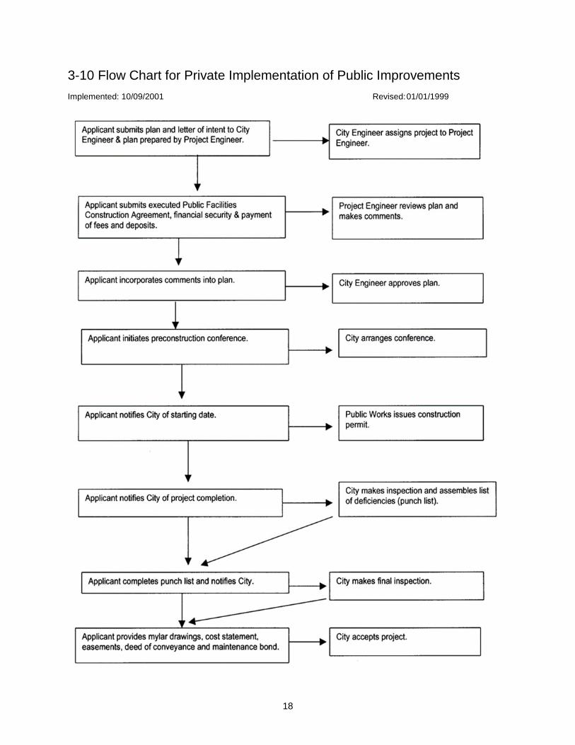
18
3-10 Flow Chart for Private Implementation of Public Improvements
Implemented: 10/09/2001 Revised: 01/01/1999
19
Section 4. Street Design Standards
4-1 Introduction
Implemented: 09/14/201 Revised: 08/01/1995
This section has been prepared to reflect City policy, outline a uniformity of methods and procedures, and
to communicate vital information to the street design engineer. The contents include maximum and
minimum design criteria for street design, as well as specification requirements for various project
construction items.
4-1.01 Design Speed
Implemented: 07/01/2007 Revised: 06/15/2007
Design speed for streets shall be 10mph over the existing posted speed or 10mph over the proposed
posted speed.
4-2 Street Classifications
Implemented: 09/14/2001 Revised: 08/01/1995
The following street classifications are to be used with the street design standards. Typical sections are
provided in Standard Plans ST-108 through ST-132.
4-2.01 Principal Arterial Street
Implemented: 09/14/2001 Revised: 08/01/1995
Standard Plan ST-132
4-2.02 Secondary Arterial Street
Implemented: 09/14/2001 Revised: 08/01/1995
Standard Plan ST-132
4-2.03 Collector Arterial Street
Implemented: 09/14/2001 Revised: 08/01/1995
Standard Plan ST-132
4-2.04 Neighborhood Collector Street
Implemented: 09/14/2001 Revised: 08/01/95
Standard Plan ST-132
4-2.05 Residential Access Street
Implemented: 09/14/2001 Revised: 08/01/1995
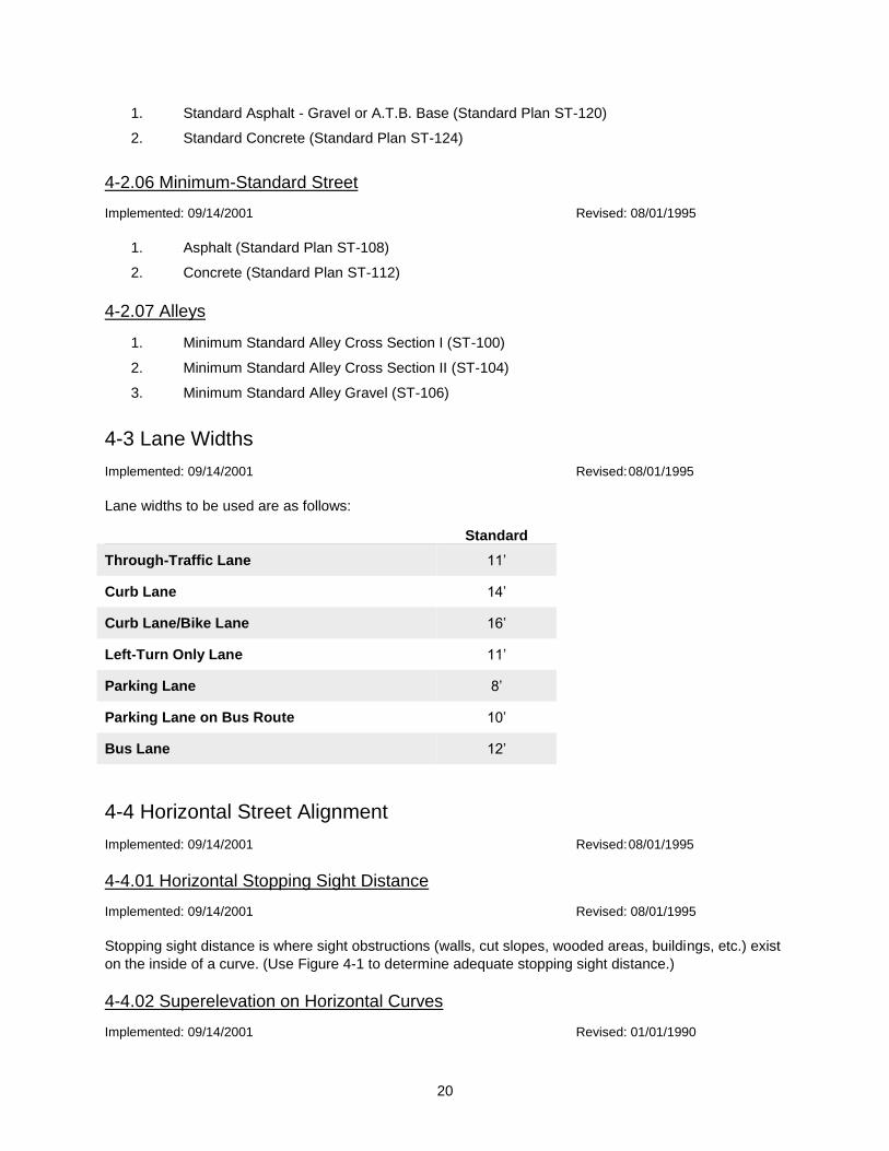
20
1. Standard Asphalt - Gravel or A.T.B. Base (Standard Plan ST-120)
2. Standard Concrete (Standard Plan ST-124)
4-2.06 Minimum-Standard Street
Implemented: 09/14/2001 Revised: 08/01/1995
1. Asphalt (Standard Plan ST-108)
2. Concrete (Standard Plan ST-112)
4-2.07 Alleys
1. Minimum Standard Alley Cross Section I (ST-100)
2. Minimum Standard Alley Cross Section II (ST-104)
3. Minimum Standard Alley Gravel (ST-106)
4-3 Lane Widths
Implemented: 09/14/2001 Revised: 08/01/1995
Lane widths to be used are as follows:
Standard
Through-Traffic Lane 11’
Curb Lane 14’
Curb Lane/Bike Lane 16’
Left-Turn Only Lane 11’
Parking Lane 8’
Parking Lane on Bus Route 10’
Bus Lane 12’
4-4 Horizontal Street Alignment
Implemented: 09/14/2001 Revised: 08/01/1995
4-4.01 Horizontal Stopping Sight Distance
Implemented: 09/14/2001 Revised: 08/01/1995
Stopping sight distance is where sight obstructions (walls, cut slopes, wooded areas, buildings, etc.) exist
on the inside of a curve. (Use Figure 4-1 to determine adequate stopping sight distance.)
4-4.02 Superelevation on Horizontal Curves
Implemented: 09/14/2001 Revised: 01/01/1990
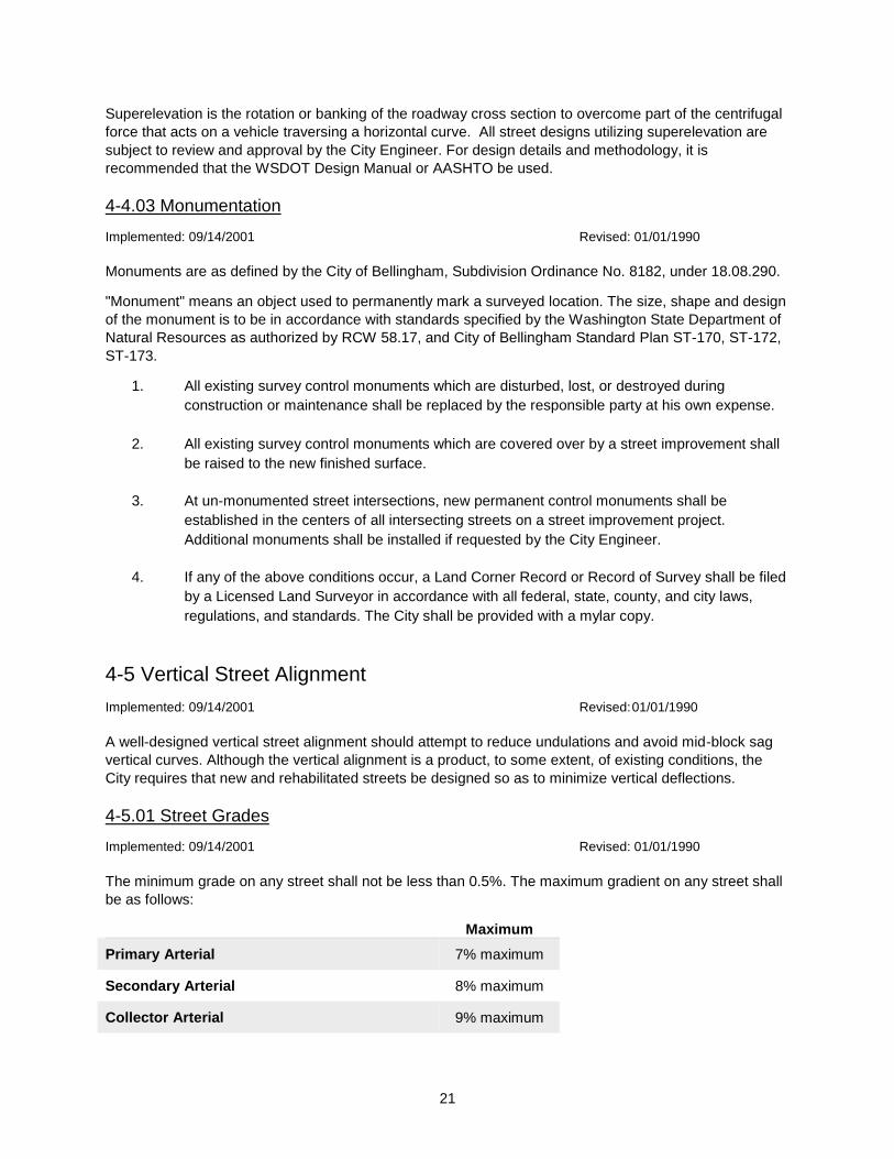
21
Superelevation is the rotation or banking of the roadway cross section to overcome part of the centrifugal
force that acts on a vehicle traversing a horizontal curve. All street designs utilizing superelevation are
subject to review and approval by the City Engineer. For design details and methodology, it is
recommended that the WSDOT Design Manual or AASHTO be used.
4-4.03 Monumentation
Implemented: 09/14/2001 Revised: 01/01/1990
Monuments are as defined by the City of Bellingham, Subdivision Ordinance No. 8182, under 18.08.290.
"Monument" means an object used to permanently mark a surveyed location. The size, shape and design
of the monument is to be in accordance with standards specified by the Washington State Department of
Natural Resources as authorized by RCW 58.17, and City of Bellingham Standard Plan ST-170, ST-172,
ST-173.
1. All existing survey control monuments which are disturbed, lost, or destroyed during
construction or maintenance shall be replaced by the responsible party at his own expense.
2. All existing survey control monuments which are covered over by a street improvement shall
be raised to the new finished surface.
3. At un-monumented street intersections, new permanent control monuments shall be
established in the centers of all intersecting streets on a street improvement project.
Additional monuments shall be installed if requested by the City Engineer.
4. If any of the above conditions occur, a Land Corner Record or Record of Survey shall be filed
by a Licensed Land Surveyor in accordance with all federal, state, county, and city laws,
regulations, and standards. The City shall be provided with a mylar copy.
4-5 Vertical Street Alignment
Implemented: 09/14/2001 Revised: 01/01/1990
A well-designed vertical street alignment should attempt to reduce undulations and avoid mid-block sag
vertical curves. Although the vertical alignment is a product, to some extent, of existing conditions, the
City requires that new and rehabilitated streets be designed so as to minimize vertical deflections.
4-5.01 Street Grades
Implemented: 09/14/2001 Revised: 01/01/1990
The minimum grade on any street shall not be less than 0.5%. The maximum gradient on any street shall
be as follows:
Maximum
Primary Arterial 7% maximum
Secondary Arterial 8% maximum
Collector Arterial 9% maximum
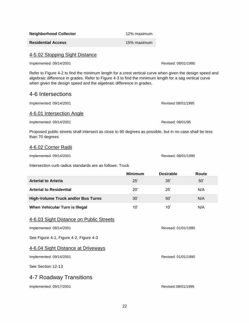
22
Neighborhood Collector 12% maximum
Residential Access 15% maximum
4-5.02 Stopping Sight Distance
Implemented: 09/14/2001 Revised: 08/01/1995
Refer to Figure 4-2 to find the minimum length for a crest vertical curve when given the design speed and
algebraic difference in grades. Refer to Figure 4-3 to find the minimum length for a sag vertical curve
when given the design speed and the algebraic difference in grades.
4-6 Intersections
Implemented: 09/14/2001 Revised: 08/01/1995
4-6.01 Intersection Angle
Implemented: 09/14/2001 Revised: 08/01/95
Proposed public streets shall intersect as close to 90 degrees as possible, but in no case shall be less
than 70 degrees
4-6.02 Corner Radii
Implemented: 09/14/2001 Revised: 08/01/1995
Intersection curb radius standards are as follows: Truck
Minimum Desirable Route
Arterial to Arteria 25’ 35’ 50’
Arterial to Residential 20’ 25’ N/A
High-Volume Truck and/or Bus Turns 30’ 50’ N/A
When Vehicular Turn is Illegal 10’ 10’ N/A
4-6.03 Sight Distance on Public Streets
Implemented: 09/14/2001 Revised: 01/01/1995
See Figure 4-1, Figure 4-2, Figure 4-3
4-6.04 Sight Distance at Driveways
Implemented: 09/14/2001 Revised: 01/01/1990
See Section 12-13
4-7 Roadway Transitions
Implemented: 09/17/2001 Revised: 08/01/1995
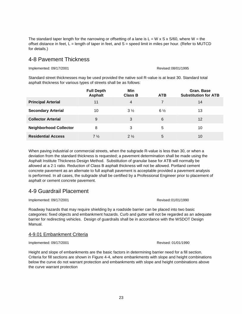
23
The standard taper length for the narrowing or offsetting of a lane is L = W x S x S/60, where W = the
offset distance in feet, L = length of taper in feet, and S = speed limit in miles per hour. (Refer to MUTCD
for details.)
4-8 Pavement Thickness
Implemented: 09/17/2001 Revised: 08/01/1995
Standard street thicknesses may be used provided the native soil R-value is at least 30. Standard total
asphalt thickness for various types of streets shall be as follows:
Full Depth Asphalt
Min Class B
ATB
Gran. Base Substitution for ATB
Principal Arterial 11 4 7 14
Secondary Arterial 10 3 ½ 6 ½ 13
Collector Arterial 9 3 6 12
Neighborhood Collector 8 3 5 10
Residential Access 7 ½ 2 ½ 5 10
When paving industrial or commercial streets, when the subgrade R-value is less than 30, or when a
deviation from the standard thickness is requested; a pavement determination shall be made using the
Asphalt Institute Thickness Design Method. Substitution of granular base for ATB will normally be
allowed at a 2:1 ratio. Reduction of Class B asphalt thickness will not be allowed. Portland cement
concrete pavement as an alternate to full asphalt pavement is acceptable provided a pavement analysis
is performed. In all cases, the subgrade shall be certified by a Professional Engineer prior to placement of
asphalt or cement concrete pavement.
4-9 Guardrail Placement
Implemented: 09/17/2001 Revised: 01/01/1990
Roadway hazards that may require shielding by a roadside barrier can be placed into two basic
categories: fixed objects and embankment hazards. Curb and gutter will not be regarded as an adequate
barrier for redirecting vehicles. Design of guardrails shall be in accordance with the WSDOT Design
Manual.
4-9.01 Embankment Criteria
Implemented: 09/17/2001 Revised: 01/01/1990
Height and slope of embankments are the basic factors in determining barrier need for a fill section.
Criteria for fill sections are shown in Figure 4-4, where embankments with slope and height combinations
below the curve do not warrant protection and embankments with slope and height combinations above
the curve warrant protection
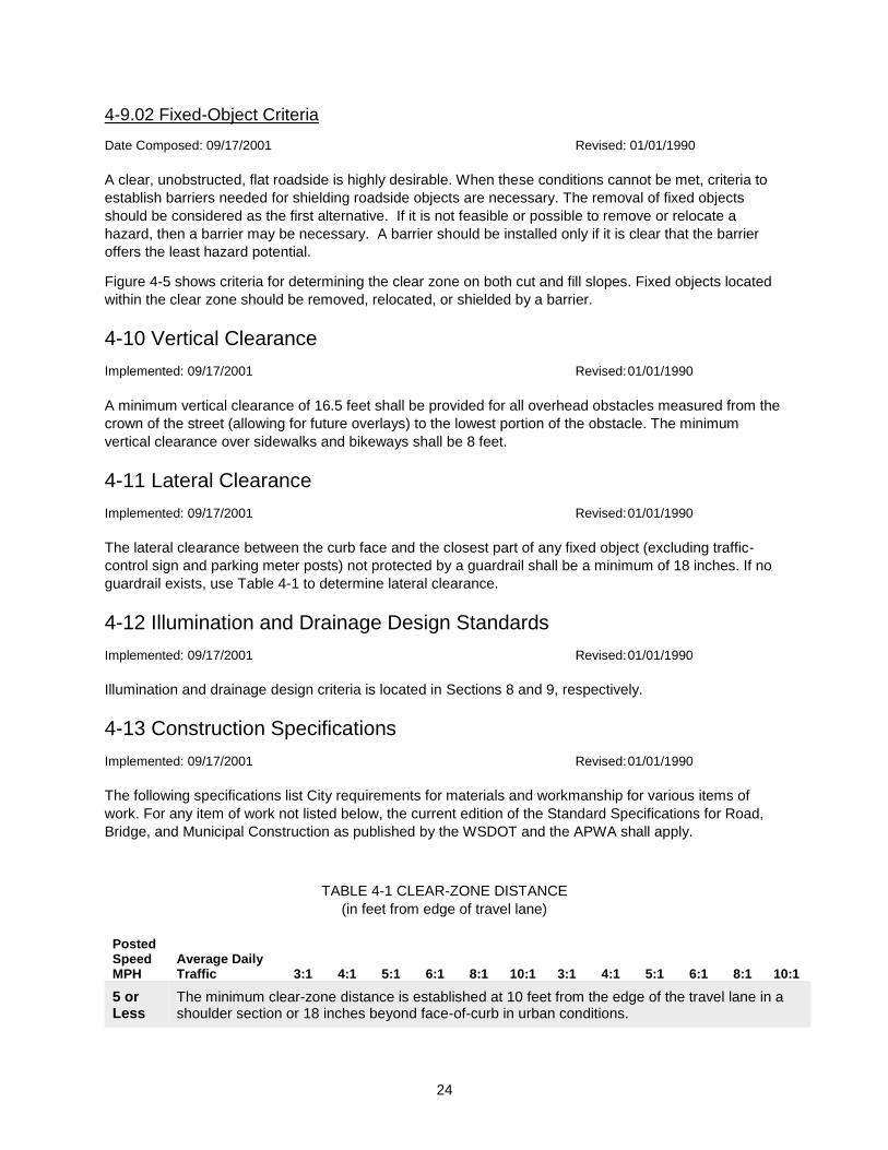
24
4-9.02 Fixed-Object Criteria
Date Composed: 09/17/2001 Revised: 01/01/1990
A clear, unobstructed, flat roadside is highly desirable. When these conditions cannot be met, criteria to
establish barriers needed for shielding roadside objects are necessary. The removal of fixed objects
should be considered as the first alternative. If it is not feasible or possible to remove or relocate a
hazard, then a barrier may be necessary. A barrier should be installed only if it is clear that the barrier
offers the least hazard potential.
Figure 4-5 shows criteria for determining the clear zone on both cut and fill slopes. Fixed objects located
within the clear zone should be removed, relocated, or shielded by a barrier.
4-10 Vertical Clearance
Implemented: 09/17/2001 Revised: 01/01/1990
A minimum vertical clearance of 16.5 feet shall be provided for all overhead obstacles measured from the
crown of the street (allowing for future overlays) to the lowest portion of the obstacle. The minimum
vertical clearance over sidewalks and bikeways shall be 8 feet.
4-11 Lateral Clearance
Implemented: 09/17/2001 Revised: 01/01/1990
The lateral clearance between the curb face and the closest part of any fixed object (excluding traffic-
control sign and parking meter posts) not protected by a guardrail shall be a minimum of 18 inches. If no
guardrail exists, use Table 4-1 to determine lateral clearance.
4-12 Illumination and Drainage Design Standards
Implemented: 09/17/2001 Revised: 01/01/1990
Illumination and drainage design criteria is located in Sections 8 and 9, respectively.
4-13 Construction Specifications
Implemented: 09/17/2001 Revised: 01/01/1990
The following specifications list City requirements for materials and workmanship for various items of
work. For any item of work not listed below, the current edition of the Standard Specifications for Road,
Bridge, and Municipal Construction as published by the WSDOT and the APWA shall apply.
TABLE 4-1 CLEAR-ZONE DISTANCE
(in feet from edge of travel lane)
Posted Speed MPH
Average Daily Traffic 3:1 4:1 5:1 6:1 8:1 10:1 3:1 4:1 5:1 6:1 8:1 10:1
5 or Less
The minimum clear-zone distance is established at 10 feet from the edge of the travel lane in a shoulder section or 18 inches beyond face-of-curb in urban conditions.
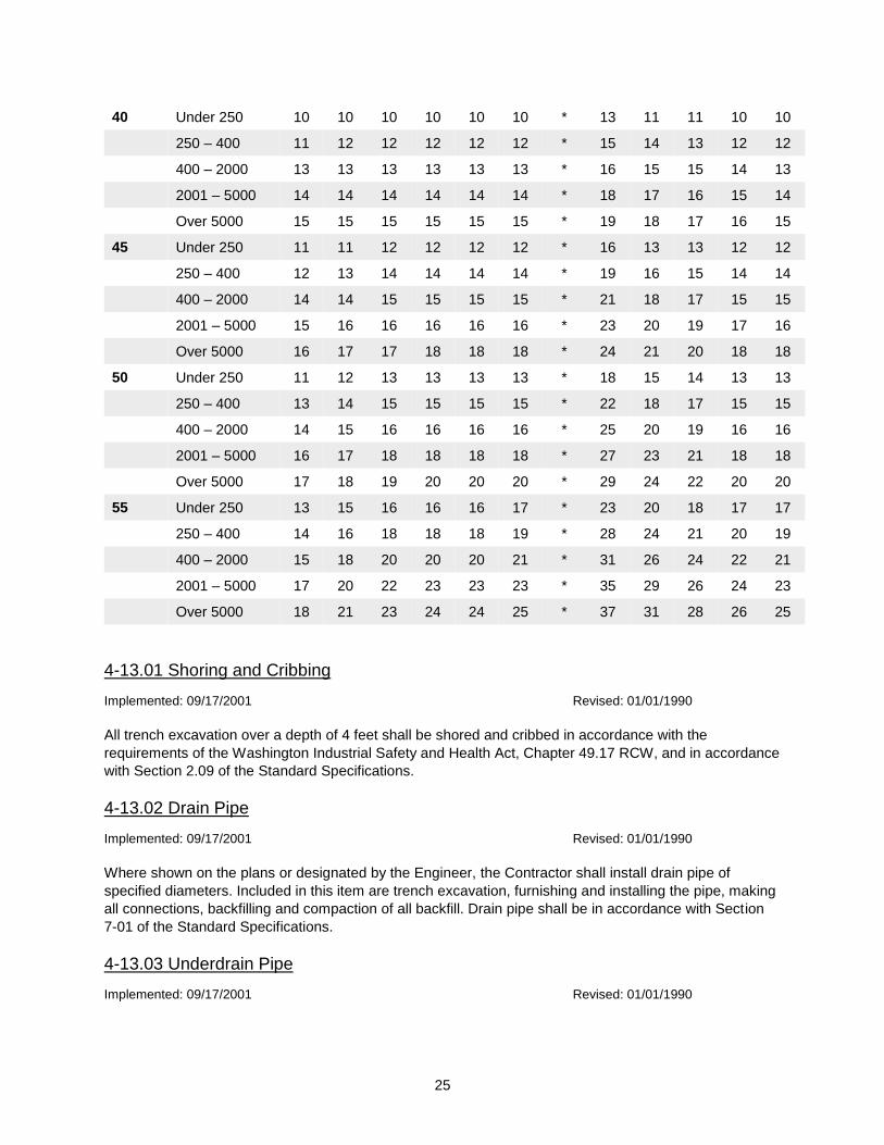
25
40 Under 250 10 10 10 10 10 10 * 13 11 11 10 10
250 – 400 11 12 12 12 12 12 * 15 14 13 12 12
400 – 2000 13 13 13 13 13 13 * 16 15 15 14 13
2001 – 5000 14 14 14 14 14 14 * 18 17 16 15 14
Over 5000 15 15 15 15 15 15 * 19 18 17 16 15
45 Under 250 11 11 12 12 12 12 * 16 13 13 12 12
250 – 400 12 13 14 14 14 14 * 19 16 15 14 14
400 – 2000 14 14 15 15 15 15 * 21 18 17 15 15
2001 – 5000 15 16 16 16 16 16 * 23 20 19 17 16
Over 5000 16 17 17 18 18 18 * 24 21 20 18 18
50 Under 250 11 12 13 13 13 13 * 18 15 14 13 13
250 – 400 13 14 15 15 15 15 * 22 18 17 15 15
400 – 2000 14 15 16 16 16 16 * 25 20 19 16 16
2001 – 5000 16 17 18 18 18 18 * 27 23 21 18 18
Over 5000 17 18 19 20 20 20 * 29 24 22 20 20
55 Under 250 13 15 16 16 16 17 * 23 20 18 17 17
250 – 400 14 16 18 18 18 19 * 28 24 21 20 19
400 – 2000 15 18 20 20 20 21 * 31 26 24 22 21
2001 – 5000 17 20 22 23 23 23 * 35 29 26 24 23
Over 5000 18 21 23 24 24 25 * 37 31 28 26 25
4-13.01 Shoring and Cribbing
Implemented: 09/17/2001 Revised: 01/01/1990
All trench excavation over a depth of 4 feet shall be shored and cribbed in accordance with the
requirements of the Washington Industrial Safety and Health Act, Chapter 49.17 RCW, and in accordance
with Section 2.09 of the Standard Specifications.
4-13.02 Drain Pipe
Implemented: 09/17/2001 Revised: 01/01/1990
Where shown on the plans or designated by the Engineer, the Contractor shall install drain pipe of
specified diameters. Included in this item are trench excavation, furnishing and installing the pipe, making
all connections, backfilling and compaction of all backfill. Drain pipe shall be in accordance with Section
7-01 of the Standard Specifications.
4-13.03 Underdrain Pipe
Implemented: 09/17/2001 Revised: 01/01/1990

26
Where shown on the plans or designated by the Engineer, the Contractor shall install underdrain pipe of
specified diameters. Included in this item are trench excavation, furnishing and installing the pipe, making
all connections, and backfilling with washed rock. Underdrain pipe shall be in accordance with Section 7-
01 of the Standard Specifications and City of Bellingham Standard Plan No. DR-525.
4-13.04 Plain Concrete Storm Sewer Pipe
Implemented: 09/17/2001 Revised: 01/01/1990
This item shall consist of constructing storm sewers of specified diameters shown on the plans or
designated by the Engineer and shall include trench excavation, furnishing and installing the pipe, making
all connections, backfilling, compaction of all backfill, and removal of existing pavement over trenches.
Storm sewer pipe alternates to concrete storm sewer pipe shall be in accordance with City of Bellingham
Standard Plan ST-36.
Furnishing and placing Class "B" bank-run gravel trench backfill may be required in locations designated
by the Engineer.
Trench excavation, bedding and pipe laying shall be performed in accordance with Section 7-04 of the
Standard Specifications. Pipe compaction and backfill shall be in accordance with Standard Plan B-11.
4-13.05 Reinforced Concrete Storm Sewer Pipe
Implemented: 09/17/2001 Revised: 01/01/1990
This item shall consist of constructing storm sewers of specified diameters shown on the plans or
designated by the Engineer and shall include trench excavation, furnishing and installing the pipe, making
all connections, backfilling, compaction of all backfill, and removal of existing pavement over trenches.
Storm sewer pipe alternates to concrete storm sewer pipe shall be in accordance with City of Bellingham
Standards.
Furnishing and placing Class "B" bank-run gravel trench backfill may be required in locations designated
by the Engineer.
Trench excavation, bedding and pipe laying shall be performed in accordance with Section 7-04 of the
Standard Specifications. Pipe compaction and backfill shall be in accordance with Standard Plan B-11.
4-13.06 Manhole Type
Implemented: 09/17/2001 Revised: 01/01/1990
This item consists of constructing manholes in accordance with the provisions of Section 7-05 of the
Standard Specifications and with the City of Bellingham Standard Plan No. SS-700.
4-13.07 Concrete Inlet
Implemented: 09/17/2001 Revised: 07/10/2014
Thru-curb inlets conforming to the requirements of Section 7-05 of the Standard Specifications shall be
installed at such locations and to such dimensions and details as shown on the plans or designated by
the Engineer and in conformance with City of Bellingham Standard Plans DR-500 and DR-505. Vaned
grates shall be used in accordance with B-30.40-01 or B-30.30.01, depending on location.
27
4-13.08 Catch Basins
Implemented: 09/17/2001 Revised: 02/19/2009
Thru-curb catch basins conforming to the requirements of Section 7-05 of the Standard Specifications
shall be constructed at the low points of the curbs and to the locations, dimensions and details as shown
on the plans or designated by the Engineer and in conformance with City of Bellingham Standard Plans
DR-500 and DR-505. Vaned grates shall be used in accordance with Standard Plan B-2b.
All joint sections in catch basin will be sealed with a layer of grout between sections.
Catch basins Type I-C having 8 inch outfall pipe shall include furnishing and installing Type 60 B-1 outlet
traps as per City of Bellingham Standard Plan No. DR-515.
4-13.09 Flared-End Section
Implemented: 09/17/2001 Revised: 01/01/1990
These items consist of installation of flared-end sections in accordance with Standard Plan B-7 at
locations shown on the plans
4-13.10 Hand-Placed Riprap
Implemented: 09/17/2001 Revised: 01/01/1990
This item consists of supplying and placing 12-inch minus crushed rock for rock line channel at a location
as shown on the plans or designated by the Engineer. All rock shall be dense, angular, sound, and
durable. It shall be free from segregation, seams, cracks, and other defects conductive to accelerated
weathering.
Bulk specific gravity shall not be less than 2.5 and absorption shall not be more than 2%.
All rock delivered to and incorporated in the project shall meet the following requirements:
100% of rock shall be 12" or less
10% maximum shall be less than 2"
2" to 12" rock shall be well-graded
4-13.11 Rock Wall
Implemented: 09/17/2001 Revised: 01/01/1990
Rock walls shall be constructed to the approximate limits shown on the plans and shall conform to the
Standard Plan included herein.
Rock used for rock walls shall be sound-ledge rock of a uniform color, and obtained from a commercial
quarry. Rock is to be free from seams or loose stratification. The rock shall have a density of at least 145
pounds per cubic foot.
All rock used in rock walls less than 3 feet in height shall be 12 inches in the least dimension and weigh a
minimum of 150 pounds. All rock in rock walls greater than 3 feet, but less than 6 feet high, shall be 18
inches in the least dimension and 500 pounds minimum weight. All rock in rock walls greater than 6 feet
high shall be 24 inches in the least dimension and 1,200 pounds minimum weight.
28
All rock is to be individually placed in rock walls. Each rock is to be placed in such a manner as to
interlock with adjoining units to provide a maximum continuity of the finished wall. Rock arrangement is to
provide uniform texture, even batter, and match the top of the embankment in a straight line. All rock
walls shall be battered uniformly to the slope shown on the Standard Plans.
Voids in the rockery face shall not be greater than 50-square inches for rocks over 3-feet high and 36-
square inches under 3-feet high. The maximum thru void area shall not exceed 15-square inches over 3-
feet high and 10-square inches under 3-feet high. All openings shall properly retain the backfill material
and not allow free spillage from behind the rock walls. All rock walls shall be backfilled in uniform layers
as construction proceeds.
A permeable membrane made of cloth woven with synthetic threads shall be placed against the wall prior
to backfilling. This filter cloth shall be no coarser than a No. 70 equivalent sieve size and shall have a
minimum thickness of 50 mils. A minimum lap distance of 2 feet shall be used and care shall be taken
during construction so as not to puncture fabric during installation.
4-13.12 Pedestrian Handrail
Implemented: 09/17/2001 Revised: 01/01/1990
This item shall include the furnishing of all materials for, and the construction of, the steel handrail on the
top of the rock retaining walls as shown and detailed in the plans and in the specifications.
All sections of the steel handrail shall be galvanized after fabrication in accordance with the provisions of
ASTM designation A123. The handrail shall not be painted, however, all erection marks and stock
numbers shall be removed before completion of the project. All welding to galvanized surfaces shall be
painted with approved galvanizing repair paint.
4-13.13 Cement Concrete Curb and Gutter
Implemented: 09/17/2001 Revised: 02/20/2008
Cement concrete curb and gutter shall be constructed where shown on the plans or as designated by the
Engineer, in accordance with Section 8-04 of the Standard Specifications and City of Bellingham
Standard Plan No. DR-500 and CG-200. Where new cement concrete curb and gutter is to be
constructed to connect to existing curbed roadway, care shall be taken to assure that no abrupt offsets in
line or grade shall be constructed which will be unsightly or impede flow in the gutter line. Depressed
curb driveway and alley openings shall be provided at such locations as directed by the Engineer or
shown on the plans and shall be paid at the same price per linear foot as cement concrete curbs and
gutter Type "A" modified. Wheelchair ramps shall be constructed at such locations as shown on the plans
or designated by the Engineer.
Curb drains shall be constructed of 2-inch P.V.C. pipe or other materials subject to approval by the
Engineer, cut to length to pass from the back-of-curb through the curb to the face-of-curb at the gutter
line. Extreme care shall be taken during subsequent sidewalk placement to ensure that drains are not
obstructed. Spacing will be maximum of 60 feet, center-to-center and/or each side of the driveways and
at such locations as designated by the Engineer to intercept existing roof drains.
Drains must be level, have their invert at the flow line of the gutter, and be normal to the back surface of
the curb.
4-13.13.01 Cement Concrete Rolled Curb
Implemented: 11/16/2001 Revised: 01/01/1990

29
Cement concrete rolled curb shall be constructed where shown on the plans or as designated by the
Engineer in accordance with City of Bellingham Standard Plans CG-204 and DR-510 and shall be
allowed as an option under the following conditions:
1. Any street of 100 or more homes per outlet would require standard vertical curbs.
2. All rolled curbing shall have a sidewalk adjacent to it which shall have a minimum thickness
of 6 inches.
3. Transition to vertical curbs will take place at intersections with arterial and through streets.
4. Handicapped ramps and vertical curb drainage grates will be utilized on corners where
applicable.
4-13.14 Integral Cement Concrete Curb
Implemented: 09/17/2001 Revised: 01/01/1990
Integral cement concrete curb shall be constructed where shown on the plans or as designated by the
Engineer in accordance with Section 8-05 of the Standard Specifications. Depressed curb driveway and
wheelchair ramp openings shall be provided at such locations as directed by the Engineer or shown on
the plans.
4-13.15 Cement Concrete Sidewalk
Implemented: 09/17/2001 Revised: 01/27/2006
Cement concrete sidewalk Type "B" shall be constructed as shown on the plans or as designated by the
Engineer, in accordance with City of Bellingham Standard Plan No. CG-230.
GENERAL NOTES: SIDEWALKS
Minimum sidewalk widths to be 5’ for residential, 8’ for commercial/business with 60’ right-of-way,
and 10’ for commercial/business with 80’ right-of-way.
Minimum radius of curb return to be 15’ on residential access streets and 20’ on arterial,
commercial and industrial streets.
Concrete shall be Class C.
3/4“ deep “V” grooves to be placed 5’ C/C.
3/8” x 2” minimum dummy joints to be placed 20’ C/C in line with contraction joints in curb.
3/8” x 4-1/2” expansion joints to be placed at curb returns, driveway section, cold joints, changes
in section, or maximum 80’ C/C. Joints to protrude 1/2” below sidewalk.
¼” x 4-1/2” expansion joints to be placed between sidewalk and back-of-curb and around all
junction boxes, meter boxes, etc.
All joints to be cleaned and edged with 1/4 radius.
30
Sidewalk to be brush-finished in traverse direction with fiber-hair brush, except at driveways
where it shall be bushed longitudinally.
Concrete shall be cured in accordance with the standard specifications.
Sidewalks in cut sections shall be drained according to Standard Plan No. CG-230.
Washed rock shall be 3/4”.
Further requirements shall be as specified in the standard specifications.
4-13.16 Cement Concrete Driveway
Implemented: 09/17/2001 Revised: 08/01/1995
Cement concrete driveways, 6 inches thick, shall be constructed where shown on the plans or designated
by the Engineer. A 2-inch layer of 3/4-inch drain rock shall be used for driveway bedding and will receive
no additional compensation under a separate pay item but shall be considered incidental to this item
4-13.17 Cobblestone Sidewalk
Implemented: 09/17/2001 Revised: 08/01/1995
This item shall consist of constructing a 4-inch cement concrete sidewalk with a cobblestone texture in
accordance with Standard Plan CG-238 and the contract plans. Specifications shall otherwise be in
accordance with those of the item, "Cement Concrete Sidewalk."
4-13.18 Asphalt Treated Base
Implemented: 09/17/2001 Revised: 08/01/1995
This item shall consist of supplying, placing and compacting in place asphalt-treated base at such
locations as shown on the plans or designated by the Engineer in accordance with Section 4-06 of the
Standard Specifications. Placement of asphalt treated base on frozen ground shall not be allowed.
4-13.19 Asphalt Concrete, Class HMA 1/2"
Implemented: 09/17/2001 Revised: 09/15/2009
This item consists of constructing Class HMA 1/2" asphaltic concrete at such locations as shown on the
plans or designated by the Engineer.
Materials and construction methods shall conform with the requirements of Section 5-04 of the Standard
Specifications except as modified herein. Connections to existing pavement shall be to a straight, neatly-
trimmed line.
The grade of asphalt used shall be PGAB conforming with Section 9-2 of the Standard Specifications.
Specification designations and AASHTO test methods for asphalt cement to be in accordance to Section
9-2 of the Standard Specifications.
The Contractor shall apply one application of an approved soil residual herbicide on all previously
unpaved areas in order to prevent vegetation damage to the asphalt pavement. The soil residual
herbicide to be used shall not have a detrimental chemical reaction to the asphalt pavement or damage

31
the pavement. Application of the herbicide shall be a uniform spray in accordance with the manufacturer's
recommendation and in accordance with the Standard Specifications.
4-13.20 Asphalt Concrete Pavement Class "G"
Implemented: 09/17/2001 Revised: 01/01/1990
This item consists of supplying and placing asphalt concrete Class "G" wearing course at such locations
as shown on the plans or designated by the Engineer. Materials and construction methods shall conform
with the requirements of Section 5-04 of the Standard Specifications.
4-13.21 Cement Concrete Pavement
Implemented: 09/17/2001 Revised: 01/01/1990
All cement concrete pavement shall be constructed in accordance with the details shown on the plans
and Section 5-05 of the Standard Specifications. The cement concrete pavement is to be constructed
either with equipment utilizing stationary side forms or by the use of slip-form paving equipment at the
option of the Contractor.
Transverse construction joints shall be sawed and the longitudinal joints may be formed or sawed at the
option of the Contractor.
4-13.22 Illumination System Complete
Implemented: 09/17/2001 Revised: 01/07/2002
This work consists of illumination construction as shown on the plans and as specified herein. The
successful Contractor shall submit four copies of shop drawings for Contractor supplied equipment to the
Engineer for approval before ordering. All material shall be obtained from a source approved by the
Engineer.
The illumination system shall be demonstrated to the Engineer and at an agreed upon time after
completion and prior to final approval. The Contractor shall provide manpower and equipment for any
necessary final adjustments and/or corrections.
4-13.22.01 Lighting Standard Base
Light standard bases shall be constructed in conformance with the attached Standard Plan No. EL-432 at
such locations shown on the plans or designated by the Engineer. The concrete and backfilling used
shall conform to the latest edition of the Standard Specifications.
The backfill material shall be controlled density fill (CDF) as per State Specification 2-09.3(1) E. If utilizing
an auger for foundation excavation, the concrete must bear against undisturbed earth. The top-of-
concrete base shall be flush finish grade.
4-13.22.02 Conduit
PVC conduit shall be furnished and installed between junction boxes and standards as detailed on the
plans. Fittings shall be the same material. Conduit shall also be installed to the extents of the project
limits to provide for future and/or existing connectivity.
All conduit to be installed in compliance with National Electric Code (NEC) at locations shown on the
plans or designated by the Engineer.

32
When installing conduit in paved areas (either shoulder or the traveled roadway), the installation shall be
accomplished by either jacking, use of an air ram, or saw cut trenching.
All trenches shall be constructed as straight and narrow as practicable to provide a minimum of pavement
disturbance. The trenches shall be saw cut on both sides of the trench and then the asphalt chipped out.
Except for the existing asphalt thickness, backfilling shall be entirely with controlled density fill (CDF) as
per State Specification 2-09.3(1)E. The Contractor shall ensure to the satisfaction of the Engineer, that all
voids are filled with CDF. The top of the trench shall be patched with compacted asphalt concrete
pavement Class "B" equaling the thickness of the existing asphalt. Care shall be taken to provide a
smooth driving surface.
4-13.22.03. Junction Boxes
Junction boxes shall conform to Standard Plan EL-452 and/or J-11a (with the exception that the J-11a
lids shall be hot-dip galvanized and bear the legend “lighting"). Junction boxes shall be furnished and
installed at such locations shown on the plans or as designated by the Engineer. The junction boxes shall
sit on patio type concrete blocks which shall be placed on 6-inch compacted crushed gravel. All cover
plates and metal surfaces for junction boxes shall be hot-dipped galvanized. Conduit into junction boxes
shall be 6 to 8 inches from the top of the box at final grade. Conduit entering through the bottom of a
junction box shall be located near the end walls to leave the major portion of the box clear. At all outlets,
conduit shall enter from the direction of the run terminating within 3 inches of the box wall nearest its entry
location and have bell ends. Care shall be taken to ensure a neat and convenient arrangement of conduit
as outlined in Section 8.20.3(5) of the Standard Specifications.
4-13.22.04 Arterial Streetlighting Standards
Streetlighting standards shall be supplied and installed on light standard bases, shall be set plumb, and
the base shall be grouted to cover leveling nuts and to fill the void under the base plat with a non-
shrinking grout. Top of concrete base shall be flush with finished grade. Unless directed by the Engineer,
standards shall match existing standards in the vicinity so long as they meet current standards.
Streetlighting standards shall be provided and installed where shown on the plans and/or as designated
by the Engineer. Streetlighting standards shall be in accordance with City of Bellingham Standard Plan
Nos. EL-404 and EL-432. Fusing shall be per WSDOT Standard Plan J-1E.
The following streetlight luminaires shall be used with the above poles.
Luminaires shall be the cutoff type with a cobra-head shaped housing. Lens shall be shatterproof, flat,
tempered glass and in an extruded-aluminum frame. Reflectors shall be provided and the lamp position
selected such that the luminaire produces an IES/ANSI Type III distribution with essentially complete light
cutoff above 75 degrees from Nadir when operated with an E-18, high-pressure sodium lamp. If not on a
circuit controlled by a service cabinet, each luminaire shall utilize a photo-cell.
The luminaire shall be bracket-arm mounted. The ballast shall be rated at 240 VAC and be of the
regulated output or constant-wattage type. The ballast shall be suitable for operating a high-pressure
sodium lamp of the specified wattage.
4-13.22.05 Alternate Arterial Streetlighting Standards
Streetlighting standards shall be provided and installed where shown on the plans and/or as designated
by the Engineer in accordance with EL-408. The standard shall be square, tapered, pre-stressed
concrete, anchor base spun hollow standards machine made in steel molds by the centrifugal process.
Pre-stressing wire, caging and other reinforcement shall be placed in a manner that assures no cracking
during normal handling. The pole shall have cast-in inserts on the side for attaching of the luminaire.
Coordination shall be made with the luminaire manufacturer to ensure that placement of the inserts
33
matches the attachment centers of the luminaire. The poles shall be Centrecon MBQ-9 meter poles or
approved equal with exposed natural aggregate finish #113 and have a 29foot, 6 inch pole height above
ground. Fusing shall be per section 4-13.22, Subsection 7, Paragraph 2 below.
The following streetlight luminaires shall be used with the above poles.
Streetlighting luminaires shall be the cutoff type with one piece extruded aluminum rectangular housing.
Lens shall be shatterproof glass, flat-tempered in an extruded aluminum frame with a medium bronze
finish. Reflectors shall be provided and the lamp position selected such that the fixture produces an
IES/ANSI Short Type II distribution with essentially complete light cutoff above 75 degrees from Nadir
when operated with a 250-watt E-18, high-pressure sodium lamp. Sterner ST light #EX25-A-10-3-25-5 is
claimed to meet these criteria. Each luminaire shall utilize a photo-cell unless controlled by a service
cabinet.
The luminaire housing shall be bracket-arm mounted. The ballast shall be rated for 240 VAC and be of
the Autoregulator type. The ballast shall be suitable for operating a high-pressure sodium lamp of the
specified wattage. The luminaire shall be bolted to the pole by means of cast inserts and this detail shall
be coordinated with the pole manufacturer to ensure proper fit. The complete luminaire assembly shall
have a medium bronze alkydemelamine baked-enamel finish. No fusing shall be located in the luminaire.
4-13.22.06 Residential Streetlighting Standards
Streetlighting standards shall be in accordance with Standard Plan EL-400 and be the same as noted in
Section 4-13.22, Subsection 5 except for the poles shall be Centrecon SEQ-5.7 or prior approved equal
with exposed natural aggregate finish #113 and shall have 18 foot 8 inch pole height above ground.
The following streetlight luminaires shall be used with the above-mentioned residential poles.
Luminaires shall be the same type as noted in Section 4-13.22, Subsection 5 except it shall be a Sterner
#EX20 70 watt HPS luminaire in medium bronze.
4-13.22.07 Wiring
All wire shall conform to the WSDOT Specifications. Conductors above grade and up the poles shall be
copper, No. 12 AWG or larger, and shall be stranded.
Insulation shall be Type THW or better, 600V minimum rated, 75 o C and be color-coded in a consistent
manner.
All wiring between j-boxes shall be 1 - #8 green wire 2 - #6 black wires stranded copper. Wiring from the
nearest j-box up the pole shall be #12 copper. Fusing will be required in the j-box next to the service and
in the j-box next to all concrete poles (see EL-400). Fuse holders shall be Buss #HEB-LW-RLA or prior
approved equal. Fusing in all metal poles shall be in accordance with WSDOT Standard Plan J-1e.
The Contractor shall provide a complete grounding system with grounding continuity throughout the
system. Ground rods and ground wire shall conform to the latest revision of the NEC.
All splices in underground illumination circuits shall be installed at junction boxes. Underground
illumination circuit splices shall employ copper crimped connectors installed with an approved tool
designed for the purpose. Shrink-on insulators (heat shrink end-caps), model HSC2-20 or epoxy splices
with clear rigid molds shall be required on splices in all underground illumination circuits.
All wiring in metal luminaire poles shall be fused with breakaway fusing per WSDOT Standard Plan J-1e.
All wiring in concrete poles shall have waterproof breakaway fusing installed in the adjacent J-box per
City of Bellingham Standard Plan EL-400.
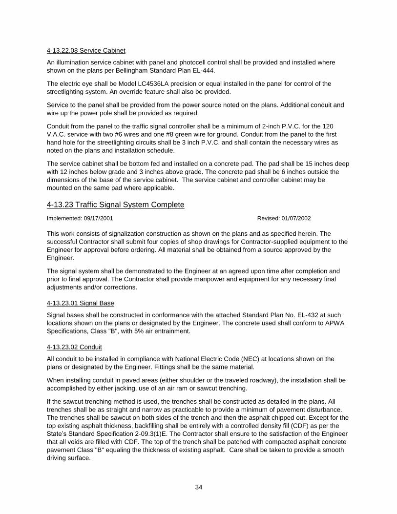
34
4-13.22.08 Service Cabinet
An illumination service cabinet with panel and photocell control shall be provided and installed where
shown on the plans per Bellingham Standard Plan EL-444.
The electric eye shall be Model LC4536LA precision or equal installed in the panel for control of the
streetlighting system. An override feature shall also be provided.
Service to the panel shall be provided from the power source noted on the plans. Additional conduit and
wire up the power pole shall be provided as required.
Conduit from the panel to the traffic signal controller shall be a minimum of 2-inch P.V.C. for the 120
V.A.C. service with two #6 wires and one #8 green wire for ground. Conduit from the panel to the first
hand hole for the streetlighting circuits shall be 3 inch P.V.C. and shall contain the necessary wires as
noted on the plans and installation schedule.
The service cabinet shall be bottom fed and installed on a concrete pad. The pad shall be 15 inches deep
with 12 inches below grade and 3 inches above grade. The concrete pad shall be 6 inches outside the
dimensions of the base of the service cabinet. The service cabinet and controller cabinet may be
mounted on the same pad where applicable.
4-13.23 Traffic Signal System Complete
Implemented: 09/17/2001 Revised: 01/07/2002
This work consists of signalization construction as shown on the plans and as specified herein. The
successful Contractor shall submit four copies of shop drawings for Contractor-supplied equipment to the
Engineer for approval before ordering. All material shall be obtained from a source approved by the
Engineer.
The signal system shall be demonstrated to the Engineer at an agreed upon time after completion and
prior to final approval. The Contractor shall provide manpower and equipment for any necessary final
adjustments and/or corrections.
4-13.23.01 Signal Base
Signal bases shall be constructed in conformance with the attached Standard Plan No. EL-432 at such
locations shown on the plans or designated by the Engineer. The concrete used shall conform to APWA
Specifications, Class "B", with 5% air entrainment.
4-13.23.02 Conduit
All conduit to be installed in compliance with National Electric Code (NEC) at locations shown on the
plans or designated by the Engineer. Fittings shall be the same material.
When installing conduit in paved areas (either shoulder or the traveled roadway), the installation shall be
accomplished by either jacking, use of an air ram or sawcut trenching.
If the sawcut trenching method is used, the trenches shall be constructed as detailed in the plans. All
trenches shall be as straight and narrow as practicable to provide a minimum of pavement disturbance.
The trenches shall be sawcut on both sides of the trench and then the asphalt chipped out. Except for the
top existing asphalt thickness, backfilling shall be entirely with a controlled density fill (CDF) as per the
State’s Standard Specification 2-09.3(1)E. The Contractor shall ensure to the satisfaction of the Engineer
that all voids are filled with CDF. The top of the trench shall be patched with compacted asphalt concrete
pavement Class "B" equaling the thickness of existing asphalt. Care shall be taken to provide a smooth
driving surface.
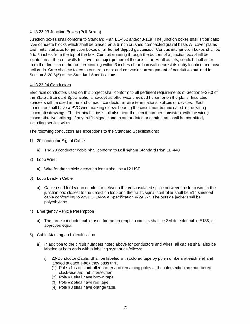
35
4-13.23.03 Junction Boxes (Pull Boxes)
Junction boxes shall conform to Standard Plan EL-452 and/or J-11a. The junction boxes shall sit on patio
type concrete blocks which shall be placed on a 6 inch crushed compacted gravel base. All cover plates
and metal surfaces for junction boxes shall be hot-dipped galvanized. Conduit into junction boxes shall be
6 to 8 inches from the top of the box. Conduit entering through the bottom of a junction box shall be
located near the end walls to leave the major portion of the box clear. At all outlets, conduit shall enter
from the direction of the run, terminating within 3 inches of the box wall nearest its entry location and have
bell ends. Care shall be taken to ensure a neat and convenient arrangement of conduit as outlined in
Section 8-20.3(5) of the Standard Specifications.
4-13.23.04 Conductors
Electrical conductors used on this project shall conform to all pertinent requirements of Section 9-29.3 of
the State's Standard Specifications, except as otherwise provided herein or on the plans. Insulated
spades shall be used at the end of each conductor at wire terminations, splices or devices. Each
conductor shall have a PVC wire marking sleeve bearing the circuit number indicated in the wiring
schematic drawings. The terminal strips shall also bear the circuit number consistent with the wiring
schematic. No splicing of any traffic signal conductors or detector conductors shall be permitted,
including service wires.
The following conductors are exceptions to the Standard Specifications: 1) 20 conductor Signal Cable
a) The 20 conductor cable shall conform to Bellingham Standard Plan EL-448
2) Loop Wire
a) Wire for the vehicle detection loops shall be #12 USE.
3) Loop Lead-In Cable
a) Cable used for lead-in conductor between the encapsulated splice between the loop wire in the
junction box closest to the detection loop and the traffic signal controller shall be #14 shielded cable conforming to WSDOT/APWA Specification 9-29.3-7. The outside jacket shall be polyethylene.
4) Emergency Vehicle Preemption
a) The three conductor cable used for the preemption circuits shall be 3M detector cable #138, or
approved equal.
5) Cable Marking and Identification
a) In addition to the circuit numbers noted above for conductors and wires, all cables shall also be labeled at both ends with a labeling system as follows:
i) 20-Conductor Cable: Shall be labeled with colored tape by pole numbers at each end and
labeled at each J-box they pass thru. (1) Pole #1 is on controller corner and remaining poles at the intersection are numbered
clockwise around intersection. (2) Pole #1 shall have brown tape.
(3) Pole #2 shall have red tape.
(4) Pole #3 shall have orange tape.
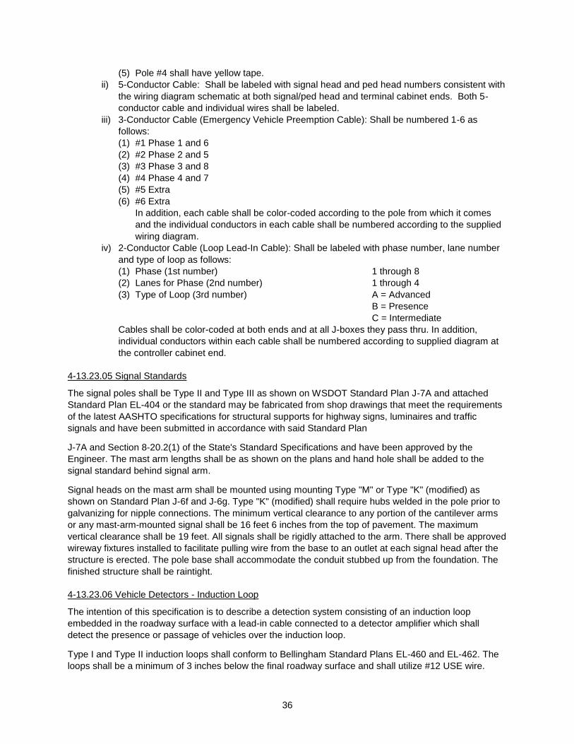
36
(5) Pole #4 shall have yellow tape.
ii) 5-Conductor Cable: Shall be labeled with signal head and ped head numbers consistent with
the wiring diagram schematic at both signal/ped head and terminal cabinet ends. Both 5-
conductor cable and individual wires shall be labeled.
iii) 3-Conductor Cable (Emergency Vehicle Preemption Cable): Shall be numbered 1-6 as
follows:
(1) #1 Phase 1 and 6
(2) #2 Phase 2 and 5
(3) #3 Phase 3 and 8
(4) #4 Phase 4 and 7
(5) #5 Extra
(6) #6 Extra
In addition, each cable shall be color-coded according to the pole from which it comes
and the individual conductors in each cable shall be numbered according to the supplied
wiring diagram.
iv) 2-Conductor Cable (Loop Lead-In Cable): Shall be labeled with phase number, lane number
and type of loop as follows:
(1) Phase (1st number) 1 through 8
(2) Lanes for Phase (2nd number) 1 through 4
(3) Type of Loop (3rd number) A = Advanced
B = Presence
C = Intermediate
Cables shall be color-coded at both ends and at all J-boxes they pass thru. In addition,
individual conductors within each cable shall be numbered according to supplied diagram at
the controller cabinet end.
4-13.23.05 Signal Standards
The signal poles shall be Type II and Type III as shown on WSDOT Standard Plan J-7A and attached
Standard Plan EL-404 or the standard may be fabricated from shop drawings that meet the requirements
of the latest AASHTO specifications for structural supports for highway signs, luminaires and traffic
signals and have been submitted in accordance with said Standard Plan
J-7A and Section 8-20.2(1) of the State's Standard Specifications and have been approved by the
Engineer. The mast arm lengths shall be as shown on the plans and hand hole shall be added to the
signal standard behind signal arm.
Signal heads on the mast arm shall be mounted using mounting Type "M" or Type "K" (modified) as
shown on Standard Plan J-6f and J-6g. Type "K" (modified) shall require hubs welded in the pole prior to
galvanizing for nipple connections. The minimum vertical clearance to any portion of the cantilever arms
or any mast-arm-mounted signal shall be 16 feet 6 inches from the top of pavement. The maximum
vertical clearance shall be 19 feet. All signals shall be rigidly attached to the arm. There shall be approved
wireway fixtures installed to facilitate pulling wire from the base to an outlet at each signal head after the
structure is erected. The pole base shall accommodate the conduit stubbed up from the foundation. The
finished structure shall be raintight.
4-13.23.06 Vehicle Detectors - Induction Loop
The intention of this specification is to describe a detection system consisting of an induction loop
embedded in the roadway surface with a lead-in cable connected to a detector amplifier which shall
detect the presence or passage of vehicles over the induction loop.
Type I and Type II induction loops shall conform to Bellingham Standard Plans EL-460 and EL-462. The
loops shall be a minimum of 3 inches below the final roadway surface and shall utilize #12 USE wire.

37
After the lead-in and loop sawcuts are completed, the slot shall be thoroughly blown out with 100 psi air
pressure so that no rocks and debris remain in the sawcut. If traffic is allowed to travel over the sawcuts
before they are sealed, they shall be blown out again before placement of the wire and sealing. The
sawcuts shall be sealed with craftco detector-loop sealant, preco sealant, 3M sealant, or prior approved
equal.
Any existing loop that is to be replaced shall either be removed or shall have each leg and ends cut with
no remaining wire being longer than 3 feet in length.
The conductors that form the induction loop and terminate in the lead-in junction box shall be joined to the
cable as follows:
Detector lead-ins shall be spliced at the junction box nearest to the induction loop. Sufficient cable length
shall always be provided to permit the preparation of wire splices 2 to 4 feet above ground.
The conductors and detector lead-in shall be twisted together then soldered, conforming to the wiring
diagram for loop identification. The soldered connections shall then be trimmed and taped, assuring good
electrical insulation of the loop pair. Pigtail splices are permissible.
Each loop pair shall then be sealed in an epoxy resin, Scotchsast size "G" (Sealing Pack #3570) or
approved equal, assuring a good seal on the splice and insulated sheaths of the conductors.
Overlap splices, parallel splices, "Y" or "T" splice kits shall not be allowed.
Loops shall be tested as per Section 8-20.3 (14) of the Standard Specifications. Documentation of test
results shall be provided to the City.
4-13.23.07 Vehicular Signal Heads
Polycarbonate heads shall not be allowed. All traffic signal heads shall meet the requirements of
Sections 9-29.16, and 9-29.16(2), of the State's Standard Specifications. All signal heads shall be 12
inches and shall contain Dialight LED signal faces.
Each conventional signal head shall have a 1/4-inch drain hole at the bottom. Signal heads shall have
square doors and shall be equipped with tunnel visors. Signal heads shall be powder coated dark olive
green. All conventional signal heads used on the project shall be by one manufacturer. Five-inch
backplates shall be provided on all vehicular signal heads.
Overhead-mounted traffic signal heads shall be adjusted in the field such that a person standing on the
pavement at a distance four times the numerical value of the speed limit expressed in feet from the stop-
bar shall see the brightest image of the red section. All signal heads shall be plumbed as viewed from the
direction which they face.
4-13.23.08 Pedestrian Signal Heads
All pedestrian signal heads employed on this project shall be LED. Pedestrian signal heads shall be the
"clamshell" type housing with an integral terminal compartment attached to the signal pole and the signal
heads affixed to the compartment by a hinge. All pedestrian signal heads used on this project shall be by
one manufacturer.
4-13.23.09 Pedestrian Push Buttons
Pedestrian push button assemblies shall be in accordance with Standard Plan J-5 except the push button
shall be magnetic and shall be made of ultra-high molecular weight polyethylene (UHMWPE). The
"Bumble Bee" pedestrian button is said to meet these specifications. The backplate shall be curved to fit
the pole. A drain hole will be drilled in the bottom of the pedestrian push button.
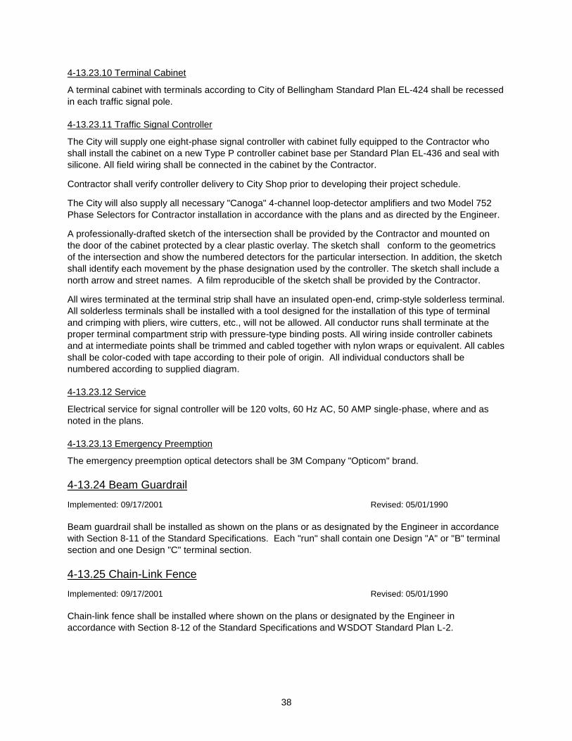
38
4-13.23.10 Terminal Cabinet
A terminal cabinet with terminals according to City of Bellingham Standard Plan EL-424 shall be recessed
in each traffic signal pole.
4-13.23.11 Traffic Signal Controller
The City will supply one eight-phase signal controller with cabinet fully equipped to the Contractor who
shall install the cabinet on a new Type P controller cabinet base per Standard Plan EL-436 and seal with
silicone. All field wiring shall be connected in the cabinet by the Contractor.
Contractor shall verify controller delivery to City Shop prior to developing their project schedule.
The City will also supply all necessary "Canoga" 4-channel loop-detector amplifiers and two Model 752
Phase Selectors for Contractor installation in accordance with the plans and as directed by the Engineer.
A professionally-drafted sketch of the intersection shall be provided by the Contractor and mounted on
the door of the cabinet protected by a clear plastic overlay. The sketch shall conform to the geometrics
of the intersection and show the numbered detectors for the particular intersection. In addition, the sketch
shall identify each movement by the phase designation used by the controller. The sketch shall include a
north arrow and street names. A film reproducible of the sketch shall be provided by the Contractor.
All wires terminated at the terminal strip shall have an insulated open-end, crimp-style solderless terminal.
All solderless terminals shall be installed with a tool designed for the installation of this type of terminal
and crimping with pliers, wire cutters, etc., will not be allowed. All conductor runs shall terminate at the
proper terminal compartment strip with pressure-type binding posts. All wiring inside controller cabinets
and at intermediate points shall be trimmed and cabled together with nylon wraps or equivalent. All cables
shall be color-coded with tape according to their pole of origin. All individual conductors shall be
numbered according to supplied diagram.
4-13.23.12 Service
Electrical service for signal controller will be 120 volts, 60 Hz AC, 50 AMP single-phase, where and as
noted in the plans.
4-13.23.13 Emergency Preemption
The emergency preemption optical detectors shall be 3M Company "Opticom" brand.
4-13.24 Beam Guardrail
Implemented: 09/17/2001 Revised: 05/01/1990
Beam guardrail shall be installed as shown on the plans or as designated by the Engineer in accordance
with Section 8-11 of the Standard Specifications. Each "run" shall contain one Design "A" or "B" terminal
section and one Design "C" terminal section.
4-13.25 Chain-Link Fence
Implemented: 09/17/2001 Revised: 05/01/1990
Chain-link fence shall be installed where shown on the plans or designated by the Engineer in
accordance with Section 8-12 of the Standard Specifications and WSDOT Standard Plan L-2.
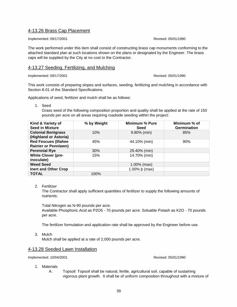
39
4-13.26 Brass Cap Placement
Implemented: 09/17/2001 Revised: 05/01/1990
The work performed under this item shall consist of constructing brass cap monuments conforming to the
attached standard plan at such locations shown on the plans or designated by the Engineer. The brass
caps will be supplied by the City at no cost to the Contractor.
4-13.27 Seeding, Fertilizing, and Mulching
Implemented: 09/17/2001 Revised: 05/01/1990
This work consists of preparing slopes and surfaces, seeding, fertilizing and mulching in accordance with
Section 8-01 of the Standard Specifications.
Applications of seed, fertilizer and mulch shall be as follows:
1. Seed
Grass seed of the following composition proportion and quality shall be applied at the rate of 150
pounds per acre on all areas requiring roadside seeding within the project:
Kind & Variety of Seed in Mixture
% by Weight Minimum % Pure Seed
Minimum % of Germination
Colonial Bentgrass (Highland or Astoria)
10% 9.80% (min) 85%
Red Fescues (Illahee Rainier or Pennlawn)
45% 44.10% (min) 90%
Perennial Rye 30% 29.40% (min)
White Clover (pre-inoculate)
15% 14.70% (min)
Weed Seed 1.00% (max)
Inert and Other Crop 1.00% þ (max)
TOTAL 100%
2. Fertilizer
The Contractor shall apply sufficient quantities of fertilizer to supply the following amounts of
nutrients:
Total Nitrogen as N-90 pounds per acre.
Available Phosphoric Acid as P2O5 - 70 pounds per acre. Soluable Potash as K2O - 70 pounds
per acre.
The fertilizer formulation and application rate shall be approved by the Engineer before use.
3. Mulch
Mulch shall be applied at a rate of 2,000 pounds per acre.
4-13.28 Seeded Lawn Installation
Implemented: 10/04/2001 Revised: 05/01/1990
1. Materials
A. Topsoil: Topsoil shall be natural, fertile, agricultural soil, capable of sustaining
vigorous plant growth. It shall be of uniform composition throughout with a mixture of
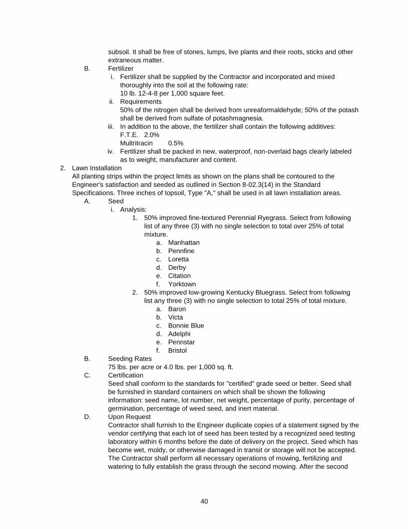
40
subsoil. It shall be free of stones, lumps, live plants and their roots, sticks and other
extraneous matter.
B. Fertilizer
i. Fertilizer shall be supplied by the Contractor and incorporated and mixed
thoroughly into the soil at the following rate:
10 lb. 12-4-8 per 1,000 square feet.
ii. Requirements
50% of the nitrogen shall be derived from unreaformaldehyde; 50% of the potash
shall be derived from sulfate of potashmagnesia.
iii. In addition to the above, the fertilizer shall contain the following additives:
F.T.E. 2.0%
Multritracin 0.5%
iv. Fertilizer shall be packed in new, waterproof, non-overlaid bags clearly labeled
as to weight, manufacturer and content.
2. Lawn Installation
All planting strips within the project limits as shown on the plans shall be contoured to the
Engineer's satisfaction and seeded as outlined in Section 8-02.3(14) in the Standard
Specifications. Three inches of topsoil, Type "A," shall be used in all lawn installation areas.
A. Seed
i. Analysis:
1. 50% improved fine-textured Perennial Ryegrass. Select from following
list of any three (3) with no single selection to total over 25% of total
mixture.
a. Manhattan
b. Pennfine
c. Loretta
d. Derby
e. Citation
f. Yorktown
2. 50% improved low-growing Kentucky Bluegrass. Select from following
list any three (3) with no single selection to total 25% of total mixture.
a. Baron
b. Victa
c. Bonnie Blue
d. Adelphi
e. Pennstar
f. Bristol
B. Seeding Rates
75 lbs. per acre or 4.0 lbs. per 1,000 sq. ft.
C. Certification
Seed shall conform to the standards for "certified" grade seed or better. Seed shall
be furnished in standard containers on which shall be shown the following
information: seed name, lot number, net weight, percentage of purity, percentage of
germination, percentage of weed seed, and inert material.
D. Upon Request
Contractor shall furnish to the Engineer duplicate copies of a statement signed by the
vendor certifying that each lot of seed has been tested by a recognized seed testing
laboratory within 6 months before the date of delivery on the project. Seed which has
become wet, moldy, or otherwise damaged in transit or storage will not be accepted.
The Contractor shall perform all necessary operations of mowing, fertilizing and
watering to fully establish the grass through the second mowing. After the second
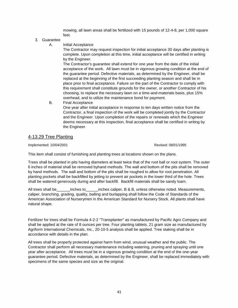
41
mowing, all lawn areas shall be fertilized with 15 pounds of 12-4-8, per 1,000 square
feet.
3. Guarantee
A. Initial Acceptance
The Contractor may request inspection for initial acceptance 30 days after planting is
complete. Upon completion at this time, initial acceptance will be certified in writing
by the Engineer.
The Contractor's guarantee shall extend for one year from the date of the initial
acceptance of the work. All lawn must be in vigorous growing condition at the end of
the guarantee period. Defective materials, as determined by the Engineer, shall be
replaced at the beginning of the first succeeding planting season and shall be in
place prior to final acceptance. Failure on the part of the Contractor to comply with
this requirement shall constitute grounds for the owner, or another Contractor of his
choosing, to replace the necessary lawn on a time-and-materials basis, plus 15%
overhead, and to utilize the maintenance bond for payment.
B. Final Acceptance
One year after initial acceptance in response to ten days written notice from the
Contractor, a final inspection of the work will be completed jointly by the Contractor
and the Engineer. Upon completion of the repairs or renewals which the Engineer
deems necessary at this inspection, final acceptance shall be certified in writing by
the Engineer.
4-13.29 Tree Planting
Implemented: 10/04/2001 Revised: 08/01/1995
This item shall consist of furnishing and planting trees at locations shown on the plans.
Trees shall be planted in pits having diameters at least twice that of the root ball or root system. The outer
6 inches of material shall be removed byhand methods. The wall and bottom of the pits shall be removed
by hand methods. The wall and bottom of the pits shall be roughed to allow for root penetration. All
planting pockets shall be backfilled by jetting to prevent air pockets in the lower third of the hole. Trees
shall be watered generously during and after backfill. Backfill materials shall be sandy loam.
All trees shall be inches to inches caliper, B & B, unless otherwise noted. Measurements,
caliper, branching, grading, quality, balling and burlapping shall follow the Code of Standards of the
American Association of Nurserymen in the American Standard for Nursery Stock. All plants shall have
natural shape.
Fertilizer for trees shall be Formula 4-2-2 "Transplanter" as manufactured by Pacific Agro Company and
shall be applied at the rate of 8 ounces per tree. Four planting tablets, 21 gram size as manufactured by
Agriform International Chemicals, Inc., 20-10-5 analysis shall be applied. Tree staking shall be in
accordance with details in the plan.
All trees shall be properly protected against harm from wind, unusual weather and the public. The
Contractor shall perform all necessary maintenance including watering, pruning and spraying until one
year after acceptance. All trees must be in a vigorous growing condition at the end of the one-year
guarantee period. Defective materials, as determined by the Engineer, shall be replaced immediately with
specimens of the same species and size as the original.
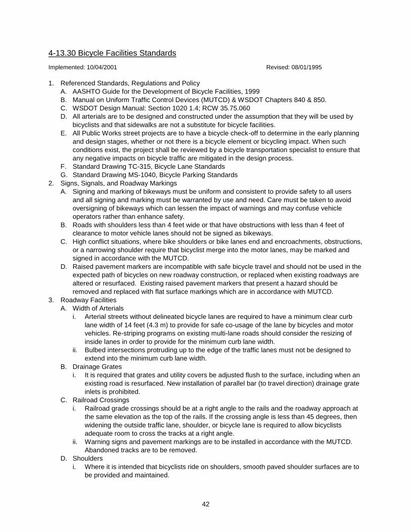
42
4-13.30 Bicycle Facilities Standards
Implemented: 10/04/2001 Revised: 08/01/1995
1. Referenced Standards, Regulations and Policy
A. AASHTO Guide for the Development of Bicycle Facilities, 1999
B. Manual on Uniform Traffic Control Devices (MUTCD) & WSDOT Chapters 840 & 850.
C. WSDOT Design Manual: Section 1020 1.4; RCW 35.75.060
D. All arterials are to be designed and constructed under the assumption that they will be used by
bicyclists and that sidewalks are not a substitute for bicycle facilities.
E. All Public Works street projects are to have a bicycle check-off to determine in the early planning
and design stages, whether or not there is a bicycle element or bicycling impact. When such
conditions exist, the project shall be reviewed by a bicycle transportation specialist to ensure that
any negative impacts on bicycle traffic are mitigated in the design process.
F. Standard Drawing TC-315, Bicycle Lane Standards
G. Standard Drawing MS-1040, Bicycle Parking Standards
2. Signs, Signals, and Roadway Markings
A. Signing and marking of bikeways must be uniform and consistent to provide safety to all users
and all signing and marking must be warranted by use and need. Care must be taken to avoid
oversigning of bikeways which can lessen the impact of warnings and may confuse vehicle
operators rather than enhance safety.
B. Roads with shoulders less than 4 feet wide or that have obstructions with less than 4 feet of
clearance to motor vehicle lanes should not be signed as bikeways.
C. High conflict situations, where bike shoulders or bike lanes end and encroachments, obstructions,
or a narrowing shoulder require that bicyclist merge into the motor lanes, may be marked and
signed in accordance with the MUTCD.
D. Raised pavement markers are incompatible with safe bicycle travel and should not be used in the
expected path of bicycles on new roadway construction, or replaced when existing roadways are
altered or resurfaced. Existing raised pavement markers that present a hazard should be
removed and replaced with flat surface markings which are in accordance with MUTCD.
3. Roadway Facilities
A. Width of Arterials
i. Arterial streets without delineated bicycle lanes are required to have a minimum clear curb
lane width of 14 feet (4.3 m) to provide for safe co-usage of the lane by bicycles and motor
vehicles. Re-striping programs on existing multi-lane roads should consider the resizing of
inside lanes in order to provide for the minimum curb lane width.
ii. Bulbed intersections protruding up to the edge of the traffic lanes must not be designed to
extend into the minimum curb lane width.
B. Drainage Grates
i. It is required that grates and utility covers be adjusted flush to the surface, including when an
existing road is resurfaced. New installation of parallel bar (to travel direction) drainage grate
inlets is prohibited.
C. Railroad Crossings
i. Railroad grade crossings should be at a right angle to the rails and the roadway approach at
the same elevation as the top of the rails. If the crossing angle is less than 45 degrees, then
widening the outside traffic lane, shoulder, or bicycle lane is required to allow bicyclists
adequate room to cross the tracks at a right angle.
ii. Warning signs and pavement markings are to be installed in accordance with the MUTCD.
Abandoned tracks are to be removed.
D. Shoulders
i. Where it is intended that bicyclists ride on shoulders, smooth paved shoulder surfaces are to
be provided and maintained.
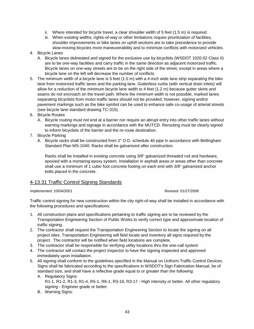
43
ii. Where intended for bicycle travel, a clear shoulder width of 5 feet (1.5 m) is required.
iii. When existing widths, rights-of-way or other limitations require prioritization of facilities,
shoulder improvements or bike lanes on uphill sections are to take precedence to provide
slow-moving bicycles more maneuverability and to minimize conflicts with motorized vehicles.
4. Bicycle Lanes
A. Bicycle lanes delineated and signed for the exclusive use by bicyclists (WSDOT 1020.02 Class II)
are to be one-way facilities and carry traffic in the same direction as adjacent motorized traffic.
Bicycle lanes on one-way streets are to be on the right side of the street, except in areas where a
bicycle lane on the left will decrease the number of conflicts.
5. The minimum width of a bicycle lane is 5 feet (1.5 m) with a 4-inch wide lane strip separating the bike
lane from motorized traffic lanes and the parking lane. Gutterless curbs (with vertical drain inlets) will
allow for a reduction of the minimum bicycle lane width to 4 feet (1.2 m) because gutter skirts and
seams do not encroach on the travel path. Where the minimum width is not possible, marked lanes
separating bicyclists from motor-traffic lanes should not be provided; however, signing and/or
pavement markings such as the bike symbol can be used to enhance safe co-usage of arterial streets
(see bicycle lane standard drawing TC-315).
6. Bicycle Routes
A. Bicycle routing must not end at a barrier nor require an abrupt entry into other traffic lanes without
warning markings and signage in accordance with the MUTCD. Rerouting must be clearly signed
to inform bicyclists of the barrier and the re-route destination.
7. Bicycle Parking
A. Bicycle racks shall be constructed from 2" O.D. schedule 40 pipe in accordance with Bellingham
Standard Plan MS-1040. Racks shall be galvanized after construction.
Racks shall be installed in existing concrete using 3/8" galvanized threaded rod and hardware,
epoxied with a mortaring epoxy system. Installation in asphalt areas or areas other than concrete
shall use a minimum of 1 cubic foot concrete footing on each end with 3/8" galvanized anchor
bolts placed in the concrete.
4-13.31 Traffic Control Signing Standards
Implemented: 10/04/2001 Revised: 01/27/2006
Traffic control signing for new construction within the city right-of-way shall be installed in accordance with
the following procedures and specifications:
1. All construction plans and specifications pertaining to traffic signing are to be reviewed by the
Transportation Engineering Section of Public Works to verify correct type and approximate location of
traffic signing.
2. The contractor shall request the Transportation Engineering Section to locate the signing on all
project sites. Transportation Engineering will field locate and inventory all signs required by the
project. The contractor will be notified when field locations are complete.
3. The contractor shall be responsible for verifying utility locations thru the one-call system
4. The contractor will contact the project inspector to have the signing inspected and approved
immediately upon installation.
5. All signing shall conform to the guidelines specified in the Manual on Uniform Traffic Control Devices.
Signs shall be fabricated according to the specifications in WSDOT's Sign Fabrication Manual, be of
standard size, and shall have a reflective grade equal to or greater than the following:
A. Regulatory Signs:
R1-1, R1-2, R1-3, R1-4, R5-1, R6-1, R3-16, R3-17 - High intensity or better. All other regulatory
signing - Engineer grade or better.
B. Warning Signs:
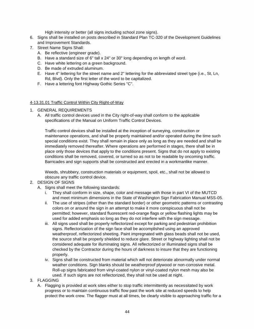
44
High intensity or better (all signs including school zone signs).
6. Signs shall be installed on posts described in Standard Plan TC-320 of the Development Guidelines
and Improvement Standards.
7. Street Name Signs Shall:
A. Be reflective (engineer grade).
B. Have a standard size of 6" tall x 24" or 30" long depending on length of word.
C. Have white lettering on a green background.
D. Be made of extruded aluminum.
E. Have 4" lettering for the street name and 2" lettering for the abbreviated street type (i.e., St, Ln,
Rd, Blvd). Only the first letter of the word to be capitalized.
F. Have a lettering font Highway Gothic Series "C".
4-13.31.01 Traffic Control Within City Right-of-Way
1. GENERAL REQUIREMENTS
A. All traffic control devices used in the City right-of-way shall conform to the applicable
specifications of the Manual on Uniform Traffic Control Devices.
Traffic control devices shall be installed at the inception of surveying, construction or
maintenance operations, and shall be properly maintained and/or operated during the time such
special conditions exist. They shall remain in place only as long as they are needed and shall be
immediately removed thereafter. Where operations are performed in stages, there shall be in
place only those devices that apply to the conditions present. Signs that do not apply to existing
conditions shall be removed, covered, or turned so as not to be readable by oncoming traffic.
Barricades and sign supports shall be constructed and erected in a workmanlike manner.
Weeds, shrubbery, construction materials or equipment, spoil, etc., shall not be allowed to
obscure any traffic control device.
2. DESIGN OF SIGNS
A. Signs shall meet the following standards:
i. They shall conform in size, shape, color and message with those in part VI of the MUTCD
and meet minimum dimensions in the State of Washington Sign Fabrication Manual MSS-05.
ii. The use of stripes (other than the standard border) or other geometric patterns or contrasting
colors on or around the sign in an attempt to make it more conspicuous shall not be
permitted; however, standard fluorescent red-orange flags or yellow flashing lights may be
used for added emphasis so long as they do not interfere with the sign message.
iii. All signs used shall be properly reflectorized except for parking and pedestrian prohibition
signs. Reflectorization of the sign face shall be accomplished using an approved
weatherproof, reflectorized sheeting. Paint impregnated with glass beads shall not be used,
the source shall be properly shielded to reduce glare. Street or highway lighting shall not be
considered adequate for illuminating signs. All reflectorized or illuminated signs shall be
checked by the Contractor during the hours of darkness to insure that they are functioning
properly.
iv. Signs shall be constructed from material which will not deteriorate abnormally under normal
weather conditions. Sign blanks should be weatherproof plywood or non-corrosive metal.
Roll-up signs fabricated from vinyl-coated nylon or vinyl-coated nylon mesh may also be
used. If such signs are not reflectorized, they shall not be used at night.
3. FLAGGING
A. Flagging is provided at work sites either to stop traffic intermittently as necessitated by work
progress or to maintain continuous traffic flow past the work site at reduced speeds to help
protect the work crew. The flagger must at all times, be clearly visible to approaching traffic for a

45
sight distance sufficient to permit proper response by the motorist to the flagging instructions and
to permit traffic to reduce speed before entering the work site area.
Flaggers and operators of construction and maintenance machinery or trucks should make every
reasonable effort to allow the driving public the right-of-way so as to avoid excessive traffic
delays.
Thus, the flagger has three basic functions -- all of equal importance:
i. To guide traffic safely through a work area.
ii. To protect the lives of the public and fellow employees working on and near the public right-
of-way.
iii. To answer courteously and intelligently reasonable questions.
B. Training: Flaggers shall complete a Washington State approved flagging course, or the
equivalent, prior to being assigned duties as a flagger.
C. Equipment: When on duty, flaggers should be appropriately dressed to alert the motorist. The
standard orange vest, hat, and other equipment shall be worn. All equipment must be
reflectorized except if it will never be used during dusk, or night conditions.
D. Tools: Hand signaling devices, such as red flags, STOP/SLOW paddles and lights are used in
controlling traffic through work areas; the STOP/SLOW paddle shall be the primary hand-
signaling device.
i. Sign paddles shall be at least 24 inches wide by 24 inches high. A rigid handle must be
provided. This combination sign may be fabricated from sheet metal or other light semi-rigid
material and have an octagonal shape. The background of the STOP face shall be red with
white letters and borders. The background of the SLOW face shall be orange with black
letters and borders. All such paddle signs must be reflectorized, unless the paddle will only
be used during daylight hours.
4-13.31.02 Traffic Control Within and Abutting the Project
Any time the Contractor’s operation is expected to disrupt the normal flow of traffic, the Contractor shall
submit a traffic control plan to the Engineer for approval. As construction progresses, each traffic control
plan shall be modified and re-submitted if deemed necessary by the Engineer. All signing and traffic
control measures shall conform to the Manual on Uniform Traffic Control Devices as adopted by the State
of Washington. Construction shall not be allowed to commence until the traffic control plan is approved.
Streets within the project limits may be closed to traffic only under the following conditions:
1. The Contractor submits a complete signing and traffic control plan for approval by the Traffic
Engineer five (5) working days prior to the desired implementation date.
2. Approved traffic controls to be in place and operational before commencement of construction.
3. The Contractor shall have total responsibility for the procurement, installation and maintenance of all
traffic control devices required for the duration of the contract.
4. The Contractor shall not close or cause to be closed, any arterial street or portion thereof between 7
a.m. and 9 a.m. or 4 p.m. and 6 p.m., unless otherwise approved by the Traffic Engineer.
All costs encountered in the maintenance of traffic, including the placement of traffic cones, construction
signs, detours, etc., and traffic control within the abutting the project as specified above and in the
Standard Specifications shall generally be considered incidental to construction and no compensation
shall be allowed; any allowance for traffic control labor is, however, an exception.
The Contractor shall an acceptable means of securing signs, cones and barricades to prevent them from
being wind-blown or tipped while in service. A penalty of twenty dollars ($20.00) per day will be assessed
46
for each traffic control device which is not in its proper position because of poor installation techniques or
lack of maintenance by the Contractor.
4-13.31.03 Notification of Adjacent Residents and Businesses
The Contractor shall notify residents and business occupants in writing a minimum of 36 hours and a
maximum of 72 hours prior to any work affecting access or service. A daily notification record shall be
maintained during the life of the contract. A copy of the notification record shall be supplied to the
Engineer upon request. Access interruptions shall be minimized whenever possible. Any costs associated
with these requirements shall be considered incidental to other items of work.

47
Section 5. Sanitary Sewer System
5-1 Introduction
Implemented: 10/04/2001 Revised: 06/01/1997
The City of Bellingham requires sanitary sewer construction plan submittal on development projects when
improvements are proposed within public right-of-way or an easement. The following chapter has been
developed to assist in preparation of sewer construction plans. It includes items pertinent for the City's
review and reflects established professional civil engineering practice for preparation of construction
plans. Three sets of plans must be submitted to the Public Works Department for initial review.
5-2 Criteria for Sewage Design
Implemented: 10/04/2001 Revised: 06/01/1997
This section serves as a guide for the design of sewage collection systems for the City of Bellingham. The
goals are:
1. To ensure that the design of sewage collection systems is consistent with public health and water
quality objectives of the State of Washington.
2. To establish a basis for the design and review of plans and specifications for sewage systems.
3. To assist the owner or their authorized engineer in the preparation of plans, specifications, reports,
and other data.
4. To guide departments in their determination of whether an approval, permit, and/or a certificate for a
sewage system should be issued.
5-2.01 DESIGN
Implemented: 11/09/2001 Revised: 06/01/1997
Sewer systems shall be designed and constructed to achieve total containment of sanitary wastes and
maximum exclusion of infiltration and inflow. No new combined storm water and sanitary sewers will be
allowed.
In keeping with good engineering practice and with the Uniform Plumbing Code, public sewers shall be
designed to provide gravity service to all abutting individual building lots. Installation of sewers or
utilization of sewers that cannot provide for gravity service will only be allowed if a gravity system is
considered by the City to be impractical to install.
5-2.01.01 Overflows
Implemented: 11/16/2001 Revised: 06/01/1997
No overflows in separate sewers or new overflows in existing combined sewers shall be permitted.
5-2.01.02 Calculations
Implemented: 11/16/2001 Revised: 06/01/1997
Computations and other data used for design of the sewer system shall be submitted to the Department
upon request.
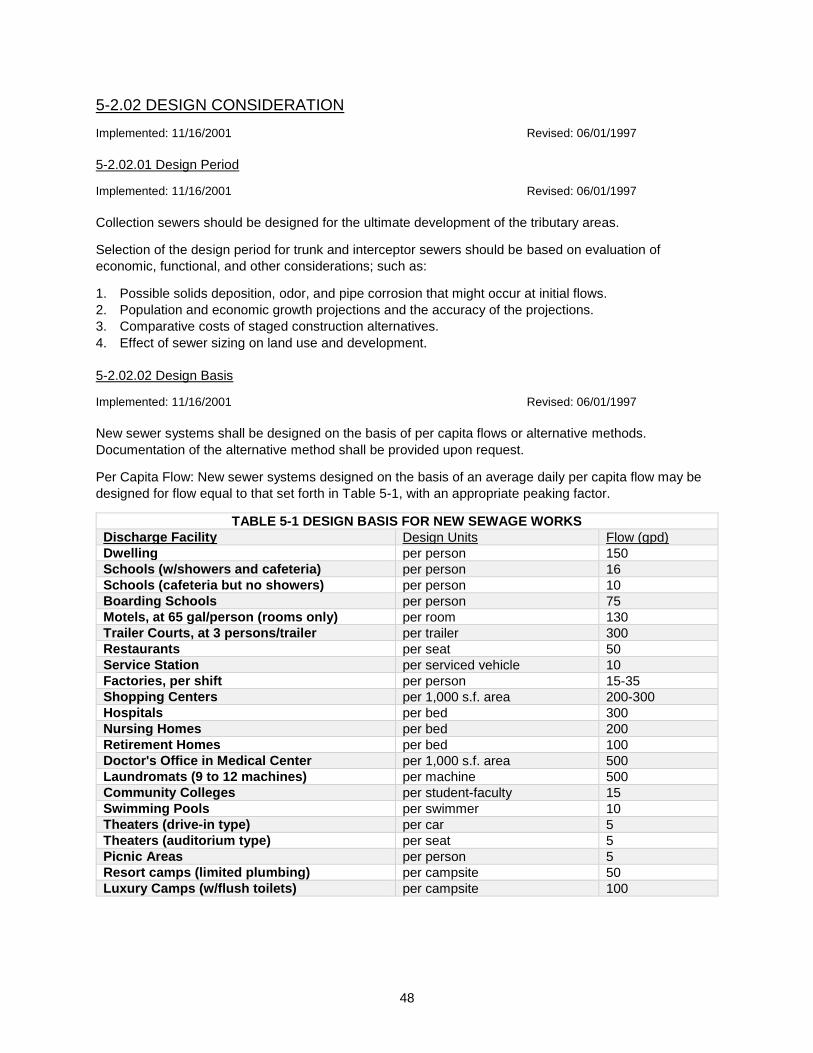
48
5-2.02 DESIGN CONSIDERATION
Implemented: 11/16/2001 Revised: 06/01/1997
5-2.02.01 Design Period
Implemented: 11/16/2001 Revised: 06/01/1997
Collection sewers should be designed for the ultimate development of the tributary areas.
Selection of the design period for trunk and interceptor sewers should be based on evaluation of
economic, functional, and other considerations; such as:
1. Possible solids deposition, odor, and pipe corrosion that might occur at initial flows.
2. Population and economic growth projections and the accuracy of the projections.
3. Comparative costs of staged construction alternatives.
4. Effect of sewer sizing on land use and development.
5-2.02.02 Design Basis
Implemented: 11/16/2001 Revised: 06/01/1997
New sewer systems shall be designed on the basis of per capita flows or alternative methods.
Documentation of the alternative method shall be provided upon request.
Per Capita Flow: New sewer systems designed on the basis of an average daily per capita flow may be
designed for flow equal to that set forth in Table 5-1, with an appropriate peaking factor.
TABLE 5-1 DESIGN BASIS FOR NEW SEWAGE WORKS
Discharge Facility Design Units Flow (gpd)
Dwelling per person 150
Schools (w/showers and cafeteria) per person 16
Schools (cafeteria but no showers) per person 10
Boarding Schools per person 75
Motels, at 65 gal/person (rooms only) per room 130
Trailer Courts, at 3 persons/trailer per trailer 300
Restaurants per seat 50
Service Station per serviced vehicle 10
Factories, per shift per person 15-35
Shopping Centers per 1,000 s.f. area 200-300
Hospitals per bed 300
Nursing Homes per bed 200
Retirement Homes per bed 100
Doctor's Office in Medical Center per 1,000 s.f. area 500
Laundromats (9 to 12 machines) per machine 500
Community Colleges per student-faculty 15
Swimming Pools per swimmer 10
Theaters (drive-in type) per car 5
Theaters (auditorium type) per seat 5
Picnic Areas per person 5
Resort camps (limited plumbing) per campsite 50
Luxury Camps (w/flush toilets) per campsite 100

49
These figures are assumed to cover normal infiltration, but an additional allowance should be made
where conditions are unfavorable. If there is an existing water system in the area, water consumption
figures can be used to help substantiate the selected per capita flow.
Generally, the sewers should be designed to carry, when running full, not less than the following:
1. Lateral and Submains:
"Minimum peak" design flow should be not less than 400 percent of the average. "Lateral" is defined
as a sewer that has no other common sewers discharging into it. "Submain" is defined as a sewer
that receives flow from one or more lateral sewers.
2. Main, Trunk, and Interceptor Sewers:
"Minimum peak" design flow should be not less than 250 percent of the average design flow. "Main"
or "trunk" is defined as a sewer that receives flow from one or more submains. "Interceptor" is
defined as a sewer that receives flow from a number of main or trunk sewers, force mains, etc. An
alternate method for trunk sewers is to use 80 gallons per capita, per day, a peaking factor from
Figure 5-1 subject to the above limits, and 1,200 gallons per acre, per day, for infiltration and inflow.
New sewer systems may be designed by alternative methods other than on the basis of per capita
flow rates. Alternative methods may include the use of peaking factors for the contributing area,
allowances for future commercial and industrial areas, separation of infiltration and inflow from the
normal sanitary flow, and modification of per capita flow rates (based on specific data).
Documentation of the alternative method used shall be provided upon request.
5-2.02.03 Design Factors
Implemented: 11/16/2001 Revised: 01/01/1990
The following factors must be considered in the design of sanitary sewers:
1. Peak sewage flows from residential, commercial, institutional, and industrial sources
2. Groundwater infiltration
3. Topography and depth of excavation
4. Treatment plant location
5. Soil conditions
6. Pumping requirements
7. Maintenance
8. Existing sewers
9. Existing and future surface improvements
10. Controlling service connection elevations
11. Easements (See Section 2-6)
5-2.03 DESIGN AND CONSTRUCTION DETAILS
Implemented: 10/04/2001 Revised: 08/01/1992
5-2.03.01 Gravity Sewers
Implemented: 11/16/2001 Revised: 08/01/1992
1. Minimum Size: No sewer shall be less than 8 inches in diameter.
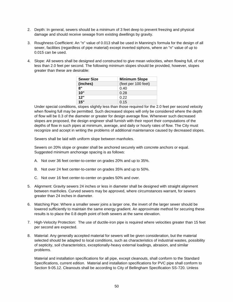
50
2. Depth: In general, sewers should be a minimum of 3 feet deep to prevent freezing and physical
damage and should receive sewage from existing dwellings by gravity.
3. Roughness Coefficient: An "n" value of 0.013 shall be used in Manning's formula for the design of all
sewer, facilities (regardless of pipe material) except inverted siphons, where an "n" value of up to
0.015 can be used.
4. Slope: All sewers shall be designed and constructed to give mean velocities, when flowing full, of not
less than 2.0 feet per second. The following minimum slopes should be provided, however, slopes
greater than these are desirable:
Sewer Size Minimum Slope
(inches) (feet per 100 feet)
8" 0.40
10" 0.28
12" 0.22
15" 0.15
Under special conditions, slopes slightly less than those required for the 2.0 feet per second velocity
when flowing full may be permitted. Such decreased slopes will only be considered where the depth
of flow will be 0.3 of the diameter or greater for design average flow. Whenever such decreased
slopes are proposed, the design engineer shall furnish with their report their computations of the
depths of flow in such pipes at minimum, average, and daily or hourly rates of flow. The City must
recognize and accept in writing the problems of additional maintenance caused by decreased slopes.
Sewers shall be laid with uniform slope between manholes.
Sewers on 20% slope or greater shall be anchored securely with concrete anchors or equal.
Suggested minimum anchorage spacing is as follows:
A. Not over 36 feet center-to-center on grades 20% and up to 35%.
B. Not over 24 feet center-to-center on grades 35% and up to 50%.
C. Not over 16 feet center-to-center on grades 50% and over.
5. Alignment: Gravity sewers 24 inches or less in diameter shall be designed with straight alignment
between manholes. Curved sewers may be approved, where circumstances warrant, for sewers
greater than 24 inches in diameter.
6. Matching Pipe: Where a smaller sewer joins a larger one, the invert of the larger sewer should be
lowered sufficiently to maintain the same energy gradient. An approximate method for securing these
results is to place the 0.8 depth point of both sewers at the same elevation.
7. High-Velocity Protection: The use of ductile-iron pipe is required where velocities greater than 15 feet
per second are expected.
8. Material: Any generally accepted material for sewers will be given consideration, but the material
selected should be adapted to local conditions, such as characteristics of industrial wastes, possibility
of septicity, soil characteristics, exceptionally-heavy external loadings, abrasion, and similar
problems.
Material and installation specifications for all pipe, except cleanouts, shall conform to the Standard
Specifications, current edition. Material and installation specifications for PVC pipe shall conform to
Section 9-05.12. Cleanouts shall be according to City of Bellingham Specification SS-720. Unless
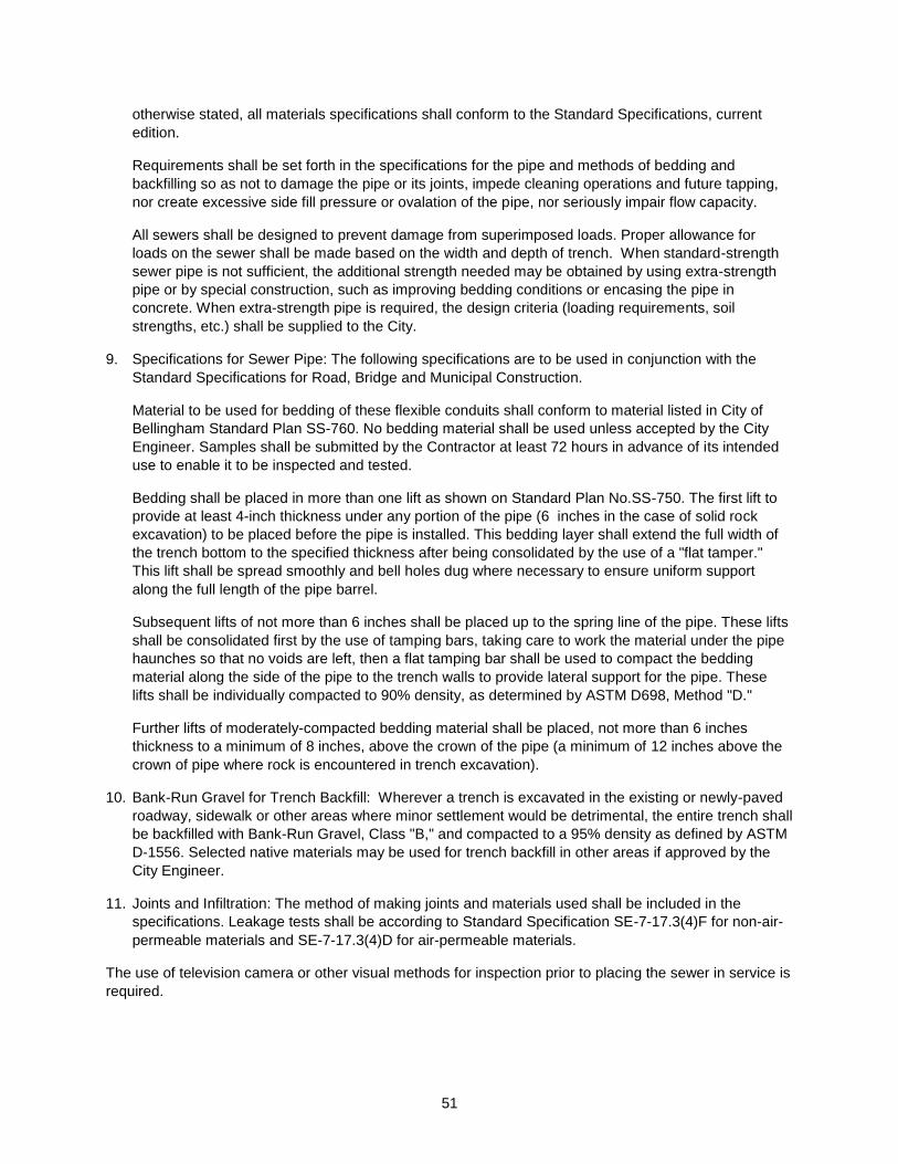
51
otherwise stated, all materials specifications shall conform to the Standard Specifications, current
edition.
Requirements shall be set forth in the specifications for the pipe and methods of bedding and
backfilling so as not to damage the pipe or its joints, impede cleaning operations and future tapping,
nor create excessive side fill pressure or ovalation of the pipe, nor seriously impair flow capacity.
All sewers shall be designed to prevent damage from superimposed loads. Proper allowance for
loads on the sewer shall be made based on the width and depth of trench. When standard-strength
sewer pipe is not sufficient, the additional strength needed may be obtained by using extra-strength
pipe or by special construction, such as improving bedding conditions or encasing the pipe in
concrete. When extra-strength pipe is required, the design criteria (loading requirements, soil
strengths, etc.) shall be supplied to the City.
9. Specifications for Sewer Pipe: The following specifications are to be used in conjunction with the
Standard Specifications for Road, Bridge and Municipal Construction.
Material to be used for bedding of these flexible conduits shall conform to material listed in City of
Bellingham Standard Plan SS-760. No bedding material shall be used unless accepted by the City
Engineer. Samples shall be submitted by the Contractor at least 72 hours in advance of its intended
use to enable it to be inspected and tested.
Bedding shall be placed in more than one lift as shown on Standard Plan No.SS-750. The first lift to
provide at least 4-inch thickness under any portion of the pipe (6 inches in the case of solid rock
excavation) to be placed before the pipe is installed. This bedding layer shall extend the full width of
the trench bottom to the specified thickness after being consolidated by the use of a "flat tamper."
This lift shall be spread smoothly and bell holes dug where necessary to ensure uniform support
along the full length of the pipe barrel.
Subsequent lifts of not more than 6 inches shall be placed up to the spring line of the pipe. These lifts
shall be consolidated first by the use of tamping bars, taking care to work the material under the pipe
haunches so that no voids are left, then a flat tamping bar shall be used to compact the bedding
material along the side of the pipe to the trench walls to provide lateral support for the pipe. These
lifts shall be individually compacted to 90% density, as determined by ASTM D698, Method "D."
Further lifts of moderately-compacted bedding material shall be placed, not more than 6 inches
thickness to a minimum of 8 inches, above the crown of the pipe (a minimum of 12 inches above the
crown of pipe where rock is encountered in trench excavation).
10. Bank-Run Gravel for Trench Backfill: Wherever a trench is excavated in the existing or newly-paved
roadway, sidewalk or other areas where minor settlement would be detrimental, the entire trench shall
be backfilled with Bank-Run Gravel, Class "B," and compacted to a 95% density as defined by ASTM
D-1556. Selected native materials may be used for trench backfill in other areas if approved by the
City Engineer.
11. Joints and Infiltration: The method of making joints and materials used shall be included in the
specifications. Leakage tests shall be according to Standard Specification SE-7-17.3(4)F for non-air-
permeable materials and SE-7-17.3(4)D for air-permeable materials.
The use of television camera or other visual methods for inspection prior to placing the sewer in service is
required.

52
5-2.03.02 Pressure Systems
Implemented: 11/16/2001 Revised: 01/01/1990
Pressure sewer systems are considered developmental technology. All pressure systems will be
designed by a professional engineer and will be judged on a case-by-case basis.
5-2.03.03 Manholes
Implemented: 11/16/2001 Revised: 10/03/2003
Manholes shall conform to City of Bellingham Standard Plan No. SS-700.
Manholes shall be installed at the end of each line of 8-inch diameter or greater unless the 8-inch line is
expected to be extended in the foreseeable future in which case, a cleanout shall be installed at the end
of the line; at all changes in grade, size, or alignment; at all intersections; and at distances not greater
than 400 feet for sewers 15 inches or less and 500 feet for sewers 18 inches to 30 inches. Cleanouts
may be used in lieu of manholes at the end of lines 8 inches in diameter and not more than 150 feet long
if they are accessible to the City's maintenance equipment. Cleanouts shall conform to City of Bellingham
Standard Plan No. SS-720.
Drop manholes shall conform in all respects to City of Bellingham Standard Plan SS-700 except for the
additional drop detail shown on Standard Plan B-18. An outside drop connection should be provided for a
sewer entering a manhole at an elevation of 24 inches or more above the manhole invert. Where the
difference in elevation between the incoming sewer and the manhole invert is less than 24 inches, the
invert should be filleted to prevent solids deposition.
The minimum diameter of manholes should be 48 inches, although larger diameters are preferable. The
minimum clear opening in the manhole frame should be 23 inches.
Manholes connecting significant industries to the system should be larger, to provide space for monitoring
and sampling equipment.
Flow channels in manholes shall be of such shape and slope to provide a smooth transition between inlet
and outlet sewers and to minimize turbulence. Channeling height shall be to the crowns of the sewers.
Benches shall be sloped from the manhole wall toward the channel to prevent accumulation of solids.
Watertight manhole covers shall be used wherever the manhole tops may be flooded. Manholes of brick
or segmented block should be waterproofed on the exterior with plaster coatings, supplemented by a
bituminous waterproof coating where groundwater conditions are unfavorable.
Direct-line connections to the manholes or to short stubs integral with the manholes should be made with
flexible joints. Flexible joints are those which permit the manholes to settle without destroying the
watertight integrity of the line connections.
Ventilation of gravity sewer systems should be considered where continuous watertight sections greater
than 1,000 feet in length are incurred.
Frames and covers shall conform to current City of Bellingham Standard Plan No. SS-700. Frames and
covers of aluminum material will be allowed if approved by the City Engineer.
All covers shall be the locking type as per SS-704.
Materials used for manhole steps should be highly corrosion resistant. The use of galvanized steel should
be avoided.
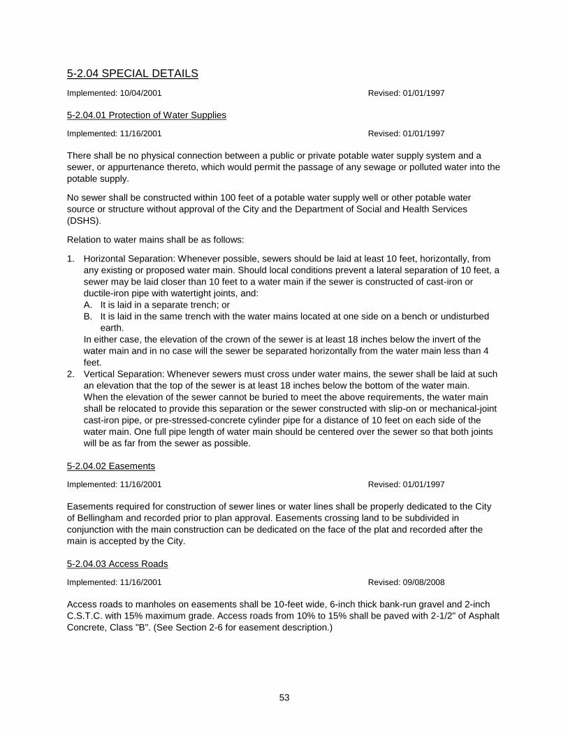
53
5-2.04 SPECIAL DETAILS
Implemented: 10/04/2001 Revised: 01/01/1997
5-2.04.01 Protection of Water Supplies
Implemented: 11/16/2001 Revised: 01/01/1997
There shall be no physical connection between a public or private potable water supply system and a
sewer, or appurtenance thereto, which would permit the passage of any sewage or polluted water into the
potable supply.
No sewer shall be constructed within 100 feet of a potable water supply well or other potable water
source or structure without approval of the City and the Department of Social and Health Services
(DSHS).
Relation to water mains shall be as follows:
1. Horizontal Separation: Whenever possible, sewers should be laid at least 10 feet, horizontally, from
any existing or proposed water main. Should local conditions prevent a lateral separation of 10 feet, a
sewer may be laid closer than 10 feet to a water main if the sewer is constructed of cast-iron or
ductile-iron pipe with watertight joints, and:
A. It is laid in a separate trench; or
B. It is laid in the same trench with the water mains located at one side on a bench or undisturbed
earth.
In either case, the elevation of the crown of the sewer is at least 18 inches below the invert of the
water main and in no case will the sewer be separated horizontally from the water main less than 4
feet.
2. Vertical Separation: Whenever sewers must cross under water mains, the sewer shall be laid at such
an elevation that the top of the sewer is at least 18 inches below the bottom of the water main.
When the elevation of the sewer cannot be buried to meet the above requirements, the water main
shall be relocated to provide this separation or the sewer constructed with slip-on or mechanical-joint
cast-iron pipe, or pre-stressed-concrete cylinder pipe for a distance of 10 feet on each side of the
water main. One full pipe length of water main should be centered over the sewer so that both joints
will be as far from the sewer as possible.
5-2.04.02 Easements
Implemented: 11/16/2001 Revised: 01/01/1997
Easements required for construction of sewer lines or water lines shall be properly dedicated to the City
of Bellingham and recorded prior to plan approval. Easements crossing land to be subdivided in
conjunction with the main construction can be dedicated on the face of the plat and recorded after the
main is accepted by the City.
5-2.04.03 Access Roads
Implemented: 11/16/2001 Revised: 09/08/2008
Access roads to manholes on easements shall be 10-feet wide, 6-inch thick bank-run gravel and 2-inch
C.S.T.C. with 15% maximum grade. Access roads from 10% to 15% shall be paved with 2-1/2" of Asphalt
Concrete, Class "B". (See Section 2-6 for easement description.)
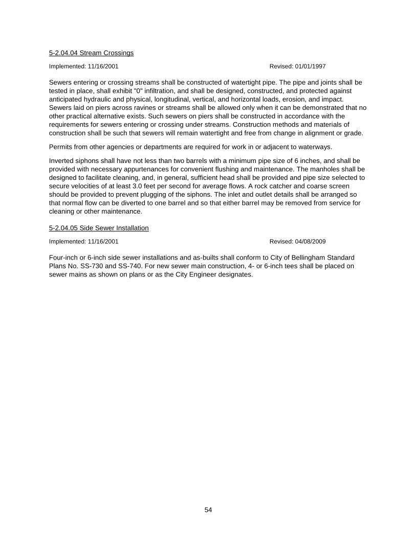
54
5-2.04.04 Stream Crossings
Implemented: 11/16/2001 Revised: 01/01/1997
Sewers entering or crossing streams shall be constructed of watertight pipe. The pipe and joints shall be
tested in place, shall exhibit "0" infiltration, and shall be designed, constructed, and protected against
anticipated hydraulic and physical, longitudinal, vertical, and horizontal loads, erosion, and impact.
Sewers laid on piers across ravines or streams shall be allowed only when it can be demonstrated that no
other practical alternative exists. Such sewers on piers shall be constructed in accordance with the
requirements for sewers entering or crossing under streams. Construction methods and materials of
construction shall be such that sewers will remain watertight and free from change in alignment or grade.
Permits from other agencies or departments are required for work in or adjacent to waterways.
Inverted siphons shall have not less than two barrels with a minimum pipe size of 6 inches, and shall be
provided with necessary appurtenances for convenient flushing and maintenance. The manholes shall be
designed to facilitate cleaning, and, in general, sufficient head shall be provided and pipe size selected to
secure velocities of at least 3.0 feet per second for average flows. A rock catcher and coarse screen
should be provided to prevent plugging of the siphons. The inlet and outlet details shall be arranged so
that normal flow can be diverted to one barrel and so that either barrel may be removed from service for
cleaning or other maintenance.
5-2.04.05 Side Sewer Installation
Implemented: 11/16/2001 Revised: 04/08/2009
Four-inch or 6-inch side sewer installations and as-builts shall conform to City of Bellingham Standard
Plans No. SS-730 and SS-740. For new sewer main construction, 4- or 6-inch tees shall be placed on
sewer mains as shown on plans or as the City Engineer designates.
55
Section 6. Water Distribution System
6-1 Introduction
Implemented: 10/04/2001 Revised: 01/01/1990
The City of Bellingham requires water distribution system construction plan submittal for development
projects when improvements are proposed within public right-of-way or in easements.
The following chapter has been developed to assist in preparation of water distribution system
construction plans. It includes items pertinent for the City's review and reflects established professional
civil engineering practice for preparation of construction plans.
Three sets of plans must be submitted to the Department of Public Works for initial review.
6-2 Water Distribution System Design Requirements
Implemented: 10/04/2001 Revised: 01/01/1990
When adding to or extending the City's water distribution system, the policies outlined in this section will
apply. These are minimum standards, however, and larger mains or other additions may be required
where deemed necessary by the Director of Public Works.
6-2.01 Minimum Size Water Main
Implemented: 10/04/2001 Revised: 01/01/1990
6-2.01.01 Residential Zones
Implemented: 11/16/2001 Revised: 01/01/1990
The minimum size water main shall be 6 inches in diameter with an average gridded spacing not to
exceed 600 feet. An 8-inch diameter main shall be used where an average grid of 600 feet is not
possible, however, the maximum ungridded length may not exceed 1,500 feet. Four-inch diameter pipes
may be allowed by the Department when future extension is not anticipated, such as in a cul-de-sac,
provided the main does not serve a fire hydrant.
6-2.01.02 Commercial, Industrial, and Institutional Zones
Implemented: 11/16/2001 Revised: 01/01/1990
The minimum size water main shall be 8 inches in diameter with an average gridded spacing not to
exceed 600 feet. A 10-inch diameter water main shall be used when the system is not gridded. The
maximum ungridded length and size of the water main may be determined by site conditions and
requirements for fire flow.
6-2.01.03 Supply Water Mains
Implemented: 11/16/2001 Revised: 01/01/1990
Where required, the minimum size supply main shall be 12 inches in diameter and shall be spaced on
approximately 3,000 foot centers. The actual size of the supply main shall be determined by its ability to
deliver water based on the peak-daily demand, plus designated fire flow.
56
6-2.02 Valve Spacing
Implemented: 10/04/2001 Revised: 03/15/2010
Valves shall be placed on each main at a junction point (node) and should be spaced along the water
main at intervals not to exceed 500 feet for pipe sizes 10 inches in diameter and above, and not to
exceed 800 feet for pipe sizes less than 10 inches in diameter. Gate valves shall be used on all diameter
pipes.
6-2.03 Fire Hydrant Spacing
Implemented: 10/04/2001 Revised: 03/01/1993
Fire hydrants shall be spaced as follows:
1. One- and two-family unit developments: no greater than 500-foot intervals along public streets or
approved fire routes.
2. All other developments: not greater than 300-foot intervals along public streets or approved fire
access routes
6-2.04 Fire Flow Rates
Implemented: 10/04/2001 Revised: 03/01/1993
All water main construction and reconstruction shall be done pursuant to a design that, when fully
implemented, will provide the fire flow requirements of the Bellingham Fire Department's fire protection
standards.
In any circumstance, when improvements which increase the fire flow requirements are made, the water
system must be upgraded to support the changes.
6-2.05 Fire Mains And Hydrants Located On Private Property
Implemented: 10/04/2001 Revised: 09/04/2002
All fire hydrants and water mains serving hydrants ill be publicly owned and maintained. A minimum 20-
foot maintenance easement shall be granted to the City and recorded for any public water main on private
property. Construction must meet City standards. (See Section 2-6 for easement description.)
Water mains on private property serving building sprinkler systems will be privately owned and
maintained as long as the main serves only one property and no hydrants are required. In this cae, the
following requirements apply:
1. An approved backflow device must be installed.
2. No domestic or other water service allowed on fire main.
3. Disinfection procedures per AWWA Section C-6-51 following Fire Department pressure test.
4. No maintenance easement is necessary.
6-3 Construction of Water Main Extension
Implemented: 10/04/2001 Revised: 01/27/2006
The petitioner shall contract with a contractor licensed to perform the construction in the State of
Washington to install a main extension as approved by the Department of Public Works.
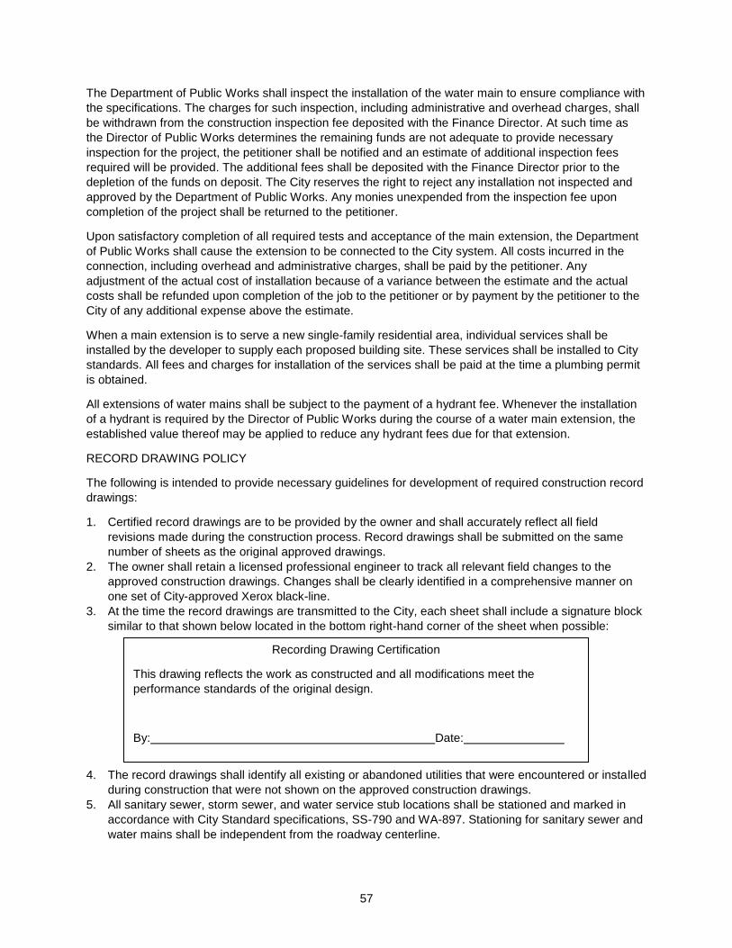
57
The Department of Public Works shall inspect the installation of the water main to ensure compliance with
the specifications. The charges for such inspection, including administrative and overhead charges, shall
be withdrawn from the construction inspection fee deposited with the Finance Director. At such time as
the Director of Public Works determines the remaining funds are not adequate to provide necessary
inspection for the project, the petitioner shall be notified and an estimate of additional inspection fees
required will be provided. The additional fees shall be deposited with the Finance Director prior to the
depletion of the funds on deposit. The City reserves the right to reject any installation not inspected and
approved by the Department of Public Works. Any monies unexpended from the inspection fee upon
completion of the project shall be returned to the petitioner.
Upon satisfactory completion of all required tests and acceptance of the main extension, the Department
of Public Works shall cause the extension to be connected to the City system. All costs incurred in the
connection, including overhead and administrative charges, shall be paid by the petitioner. Any
adjustment of the actual cost of installation because of a variance between the estimate and the actual
costs shall be refunded upon completion of the job to the petitioner or by payment by the petitioner to the
City of any additional expense above the estimate.
When a main extension is to serve a new single-family residential area, individual services shall be
installed by the developer to supply each proposed building site. These services shall be installed to City
standards. All fees and charges for installation of the services shall be paid at the time a plumbing permit
is obtained.
All extensions of water mains shall be subject to the payment of a hydrant fee. Whenever the installation
of a hydrant is required by the Director of Public Works during the course of a water main extension, the
established value thereof may be applied to reduce any hydrant fees due for that extension.
RECORD DRAWING POLICY
The following is intended to provide necessary guidelines for development of required construction record
drawings:
1. Certified record drawings are to be provided by the owner and shall accurately reflect all field
revisions made during the construction process. Record drawings shall be submitted on the same
number of sheets as the original approved drawings.
2. The owner shall retain a licensed professional engineer to track all relevant field changes to the
approved construction drawings. Changes shall be clearly identified in a comprehensive manner on
one set of City-approved Xerox black-line.
3. At the time the record drawings are transmitted to the City, each sheet shall include a signature block
similar to that shown below located in the bottom right-hand corner of the sheet when possible:
4. The record drawings shall identify all existing or abandoned utilities that were encountered or installed
during construction that were not shown on the approved construction drawings.
5. All sanitary sewer, storm sewer, and water service stub locations shall be stationed and marked in
accordance with City Standard specifications, SS-790 and WA-897. Stationing for sanitary sewer and
water mains shall be independent from the roadway centerline.
Recording Drawing Certification
This drawing reflects the work as constructed and all modifications meet the
performance standards of the original design.
By: Date:
58
6. Substantial changes made to storm drainage shall be reflected in a modified storm drainage report
and shall be certified by the professional engineer that the modifications made during construction
meet the performance standards of the original design.
7. The final project approval shall not be processed until the City has received and approved the
certified record drawings. The City Engineer may accept a deposit of 150% of the cost of preparation
of record drawings in lieu of performance. A deposit will require a commitment from the owner to (A)
complete the record drawings within 90 days; (B) hold the City harmless from any damages caused
by the delay in performance; and (C) require the engineer of record to provide free and timely
information to the City and Public.
8. All underground facilities shall be shown on the record drawings to the nearest 1-foot horizontal and
the nearest 0.1-foot vertical unless otherwise noted by the engineer. Water services shall be shown to
the nearest 5-foot horizontal and the nearest 1-foot vertical. Side sewers shall be shown to the
nearest 2-foot horizontal and the nearest 0.1-foot vertical.
RECORD DRAWINGS (SEWER AND WATER)
The purpose of this letter is to inform you that the City of Bellingham will now require the developer’s
engineer to supply us with a full set of certified record drawings upon completion of the Public Facilities
Contract. These as-built drawings will reflect the exact location of all underground and aboveground
utilities and will include, but not be limited to, the following:
1. The location of all vertical and horizontal bends in the water system.
2. The location of all water service taps into the water main.
3. The location of all water service boxes and meters with distances to the main tap and to the
corresponding property corners.
4. The locations of all water valves, hydrants, hydrant valves, and blow-offs as to distance from the
centerline and distances to the nearest property lines or property corners.
5. The location of all utilities within easements. This will include distances to the utilities from the
easement lines.
6. The location of all side sewer tees into the sewer main from the back-station manhole.
7. The location of all side sewer ends according to the attached drawings and with the additional
stipulations:
A. The ends must be tied out to the corresponding property corners.
B. The depth of the end at the location board must be noted.
8. The location of all sanitary manholes, storm sewer manholes, storm sewer catch basins and back-of-
walk drains. These locations must include distances from the centerline monuments, easement lines,
or property corners.
9. All easements will be staked in advance of utility installations to ensure that the utilities fall within the
proper boundaries. Construction offset staking will not fulfill this requirement.
6-3.01 Energizing Main Extensions
Implemented: 10/04/2001 Revised: 03/01/1993
No main extensions shall be energized other than for test purposes by duly authorized personnel until the
main extension has been accepted by the City and all fees and charges have been paid. If energizing a
main is necessary to restore service to existing customers, fire hydrants will not be activated until
acceptance of the main extension.
6-3.02 Payment For Water Mains
Implemented: 10/04/2001 Revised: 01/01/1990
Water mains placed in public rights-of-way or easements and connected to City mains may be paid for by:
59
1. The party benefiting from the installation;
2. The City;
3. A local improvement district, as provided by law; or
4. Latecomer Agreements. The City may, in accordance with state law, grant the party constructing a
new water main the right to partial reimbursement from other abutting property owners benefited by
the improvement. Such reimbursement shall be administered by the City and shall be subject to
reasonable overhead and administrative charges by the City.
6-3.03 Standards For Water Main Construction
Implemented: 10/04/2001 Revised: 01/01/1990
6-3.03.01 Pipe For Water Main
Implemented: 11/16/2001 Revised: 03/11/2014
All pipe shall be AWWA Standards H3-71, C151-71 and cement lining C104-71, and shall be ductile cast-
iron, Thickness Class 50 push-on joints or M.J. joints. The pipe shall be of 150 psi working pressure, plus
100 psi surge pressure. No PVC or AC pipe will be allowed.
Pipe laying shall meet the requirements of Section 7-09 of the Standard Specifications. All pipe shall have
minimum covering of 3.5 feet. Pipe shall be installed with bedding and back fill as specified in City of
Bellingham Standard Plan No. WA-820.
6-3.03.02 Fittings
Implemented: 11/16/2001 Revised: 03/15/2010
Material for fittings such as crosses, tees, bends, reducers and sleeves shall be ductile iron. Joints shall
be M.J. or push-on joints and shall conform to AWWA Specification C-110-71 and C-104-71. All fittings
shall have full bolting holes and no knock outs. Fittings shall be Tyler, Clow or equivalent.
6-3.03.03 Concrete Thrust Blocking
Implemented: 11/16/2001 Revised: 03/15/2010
Concrete blocking shall be as specified in City of Bellingham Standard Plan No. WA-860, or as directed
by the Project Engineer. Blocks shall be installed as specified in Section 7-09 of the Standard
Specifications. All concrete shall remain a minimum of 6 inches away from all bolts. All concrete thrust
blocks shall be formed using forms approved by City Project Engineer. No precast blocks shall be
allowed.
6-3.03.04 Connection to Existing Water Mains
Implemented: 11/16/2001 Revised: 01/01/1990
The Contractor must notify the Project Engineer of a proposed connection time at least four working days
in advance.
6-3.03.05 Hydrostatic Testing and Disinfection of Water Main
Implemented: 11/16/2001 Revised: 03/15/2010
This section shall replace Sections 7-09 of the Standard Specifications.

60
All pressure testing and leakage testing shall be conducted in accordance with Section 13 AWWA C-600-
99 Standards, with the following exceptions.
All reference to the owner furnishing any equipment used in the testing procedure is hereby deleted. The
necessary apparatus, including temporary plugs, required for testing shall be supplied by the Contractor
and subject to the Engineer's approval.
The testing shall be conducted after the piping has been completely backfilled and all thrust blocks are in
place and cured. The test sections shall be limited to sections between valves or as modified by the
Engineer; but in any event no test section shall contain more than 3,500 linear feet of pipe. Several
valved sections may be combined but these sections, when combined, shall not be greater than any
length specified above. The temporary connection will be to City of Bellingham Standard Plan No. WA-
858 with the approved backflow devices. Device shall be tested prior to activation as per WAC246-290-
490.7.(b).(IV)
The pressure test and leakage test shall be combined as follows. The test pressure shall be 200 psi,
measured at the highest elevation of the section being tested. This pressure plus 5 psi shall be
maintained for a period of one hour and the amount of makeup water required to maintain this pressure
shall be carefully measured. The allowable leakage shall not exceed the number of gallons per hour as
determined by the formula:
in which L = Allowable leakage, gallons/hour
N = Number of joints in the length of pipeline tested
D = Nominal diameter of the pipe in inches
P = Average test pressure during the leakage test, psi
If the section of pipe being tested does not meet the above requirements, the Contractor shall, at his own
expense, locate and repair the defects and retest the section as provided above.
All disinfection and bacteriological tests shall be conducted by the City's testing lab in accordance with
AWWA Section C651.
Chlorine powder or a solution of chlorine shall be continuously introduced into the pipe at the water
source by means of an adjustable feeder. The initial dose shall indicate a minimum of 50 ppm and shall
be measured at nearest blow-off or hydrant and the furthest location or locations from point of application.
An approved backflow device per Standard Plan WA-858 shall be installed by the Contractor on the City
side of the chlorine-injection device to prevent the backflow of highly-chlorinated water into the existing
service system. Before placing the lines into service a satisfactory report shall be received from the City of
Bellingham on samples collected from representative points in the new system. Samples will be collected
and bacteriological tests obtained by the Engineer or his/her representative. The pipe will not be placed
into service until a zero atypical and coliform bacteria count is obtained for two consecutive tests 24
hours apart.
All other provisions of Section 7-09 of the Standard Specifications not in conflict with the above shall
remain in effect.
The lump sum bid for hydrostatic testing and disinfection of water main shall be full compensation for
furnishing the necessary chlorine feeder and chlorine, making the necessary main taps and all labor and
other additional materials that may be required to chlorinate the main as indicated above. No additional
and/or extra compensation will be allowed in performing the hydrostatic tests and for disinfection of water
mains.
61
6-3.03.06 Water Service Transfers
Implemented: 11/16/2001 Revised: 11/10/2014
Tap installations shall meet the requirements of City of Bellingham Standard Plan No.WA-824 and WA-
826.
1. WATER SERVICE INSTALLATION - Standard 1" to 2" Water Services:
A. Both direct tap or tapping with tapping clamp and saddle must use C-C-Threaded corporations.
If the dry-tap method is used, a hole the same diameter as the service tap shall be used. Caution,
care and prudence is necessary in aligning the clamp and saddle to assure full- flow capability.
Single-strap saddles are not aceptable. Double-strap wide band stainless steel saddles
equivalent to Romac Saddle #201S shall be used.
B. Corporation taps shall make as nearly as possible a 45 angle off the vertical center line of the
main. No tap is to be made on the top of a water main.
C. Type "K" copper shall be used on water services within the public right-of-way.
D. Curb stops shall be flare by female type and located no closer than three (3) feet or farther than
five (5) feet from the property line. Any other location requires specific written approval of the
Project Engineer. Stop-and-waste curb stops are not allowed. Curb stops shall be Ford brass or
equal, flare by female type. Teflon ball type curb stops are not allowed. WA-824.
E. Cast-iron curb boxes shall be required on all services unless the City requires a meter, then see
meter box requirements.
F. All underground fittings shall be Ford Brass or equal and flared within the public right-of- way. No
sweat or compression connections are to be used. The use of Teflon tape as a sealant is
acceptable, the use of pipe dope is not acceptable.
G. The water service pipe shall have a minimum of 22" depth and a maximum of 24" depth, including
under ditch sections. To facilitate water meter installations, there shall be 24" cover to finished
grade at the curb stop location. All meters will be purchased from the City and will be installed by
the City Water Division.
H. No service is to be covered until the City Project Inspector has inspected the initial installation.
Note that all corporations must be in an ON position and all curb stops must be in the OFF
position.
I. Service testing shall be done in conjunction with water main testing. Any air relief and flushing
shall be the responsibility of the developer. City crews will operate existing valves to aid the
developer.
J. An acceptance inspection will be made by the City upon completion of all project work. During the
inspection, every service shall be turned on to its full capacity to check flow and guarantee that
each service line has been flushed. In no case shall the acceptance inspection be made until all
project work is complete. Damage incurred during other construction work on the project shall be
corrected by the developer or his agent prior to acceptance by the City.
K. The bond release inspection shall be made prior to the end of the 1-year maintenance bond
period. Any problems noted at this time shall be corrected by the developer and/or bonding
company prior to releasing the bond.
L. Staking of lots and/or property lines to assure correct water service locations is the responsibility
of the developer. Locations are to be as shown on the approved drawings. Errors due to failure to
provide a property survey or due to changing lot locations during final plat approval shall be
corrected by the developer at the time of such change or when the error is detected by the City. If
mains have been accepted the City will correct and the costs shall be the responsibility of the
developer.
M. Tools, materials and work area shall be maintained in a sanitary condition at all times. All
excavations shall be backfilled at the end of the day.
2. WATER METER BOX INSTALLATION - Requirement for Type "K" Copper Standard Sized 1" Water
Services will be installed by the City:
62
A. A minimum of 22", a maximum of 24" cover from finished grade to the service pipe shall be
maintained, except where a variance is approved by the City Engineer. There shall be 24" cover
from finish grade in the meter installation area. Note that the top of the box shall be flush with the
finished grade and that this includes the expansion material when required.
B. The curb stop shall be located within the meter box.
i. Minimum clearance of 1" from inside surface.
ii. Maximum clearance of 2" from inside surface shall be maintained from the stop.
iii. Stops shall be a minimum of 3' or a maximum of 5' from the property line within the public
right-of-way or as approved by the City, except when this places the stop in the sidewalk - in
this case the stop will be located in the planting strip. Stops shall be located outside of back
of walk drain.
C. Concrete meter box shall be standard or better. See attached standard plan. P.V.C. boxes are
not to be used.
D. Location of meter boxes.
i. If a meter box for a 1" service is to be located within the street or sidewalk area, a #3 skagit
meter traffic-type box must be used with a heavy-duty 1/4" deck plate lid or better.
ii. An expansion material must be used around the lid section to enable removal for
maintenance. The material shall be flush with the lid section to avoid any cracks or
protrusions.
iii. For 1 + 1/2" and 2" services a #2 concrete box with a steel lid must be used.
E. Caution must be exercised when setting the bottom section of a meter box to assure that the
copper has clearance in the notch area. The weight of the meter box must not be on the service
pipe.
3. PROJECT REQUIREMENTS
A. The City of Bellingham shall make the final connection of all water mains to the existing system.
B. A deposit to cover the cost of connection by the City shall be made to the City Finance Director.
The Operations Division shall supply the necessary estimate upon request by the developer or
his agent.
C. All costs, fees, or deposits relative to the total project must be paid prior to water system
acceptance. Proof of payment shall be by copies of receipts from the Finance Director specifying
for what payment was received.
D. Final cost accounting must be supplied for the entire project including separate costs for:
i. Water main and appurtenances;
ii. Fire hydrant assembly - including the tee at the main;
iii. Water services, including curb box and/or meter box when required;
iv. Sewer main trunks;
v. Side sewer connection; and/or
vi. Street construction.
E. The final project shall not be accepted until all requirements are met.
F. The Operations Division shall determine that the project has been accepted by the City prior to
connection of the water main to the City system.
6-3.03.07 Gate Valves 2" and Above
Implemented: 11/16/2001 Revised: 03/15/2010
Gate valves shall be installed with cast-iron valve boxes. Short-body valves suitable for a nonshock shut-
off pressure of 130 psi. Valves shall conform to the latest revision of AWWA Standards C-515 covering
resilient seated wedge gate valves equivalent to MH, CLOW and Kennedy valves and suitable for direct
burial as specified. Gate valves shall have bronze center stem with bronze stem nut. All valves shall be
furnished with MJ kits manufactured by Tyler, Romac or equivalent.
63
All valves shall have nonrising stems and shall open counterclockwise and shall be equipped with a 2-
inch square operating nut. Valves will be flange or M.J. joints.
All valves shall be AWWA approved.
6-3.03.08 Gate Valves 12" and Above
Implemented: 11/16/2001 Revised: 03/30/2010
This Section has been deleted
6-3.03.09 Hydrant Installation
Implemented: 10/04/2001 Revised: 03/15/2010
Hydrants shall be supplied and installed according to City of Bellingham Standard Plan No. WA-802 and
as of January 1, 1990, shall include a Storz-type fire hose adapter fitting. Hydrants shall be M&H 929,
Clow Madalion, Waterous Pacer or equivalent.
CITY OF BELLINGHAM HYDRANT SPECIFICATIONS
1. Fire hydrants shall be for common Bellingham water works service and shall be in compliance with
the latest edition of AWWA C 502 "Standard for Dry-Barrel Fire Hydrants."
2. Each hydrant shall be 5-1/4" main valve opening with "O" ring seals and traffic-type breakaway
design.
3. Hydrant operating nut shall open counter-clockwise with the direction of "open" clearly marked at top
of hydrant. Operating and cap nuts shall be pentagon in shape and the dimension shall be 1- 1/4"
point to flat (National Standard).
4. Hydrant shall be 6" inlet mechanical joint (with accessories) or as specified. Hydrant shall have two
hose and one pumper nozzle made of brass. Nozzles shall be screw type, threaded counter
clockwise into hydrant barrel and sealed to a 200 psi working pressure. Hydrants to be acceptable for
a 3-1/2' depth of bury. Hydrant to have rust-proof automatic drain.
5. Hydrant to be capable of rotating through 360 degrees.
6. Thread Specifications: Hose nozzles to be 2-1/2" inside diameter with National Standard Threads.
Pumper nozzle to be 4" inside diameter with Pacific Coast Threads as follows: 60 degree - 6 threads
per inch, pitch diameter - 4.7018", outside diameter - 4.798".
7. Each hydrant pumper port shall be equipped with a non-locking Snap-Tite Storz #FSAF/MF, 5" fitting
and blind cap (Stortz or equal). The blind cap shall be attached to the fitting with a section of aircraft
cable.
8. Hydrant to be painted red with white dome and caps. Paint shall be Rustoleum #2766 for white and
#1210 for red or equal.
9. Only hydrants of the "Corey Type" or center-stem hydrants with APWA approved rating of 200 psi
working pressure will be accepted.
10. Acceptance of any hydrant, other than a type currently in service on the City system, will be allowed
only if all necessary special repair tools and a training session for maintenance and repair is provided
at no cost to the City. Any hydrant that deviates from the specifications must be approved by the
operations engineer and/or the water superintendent.
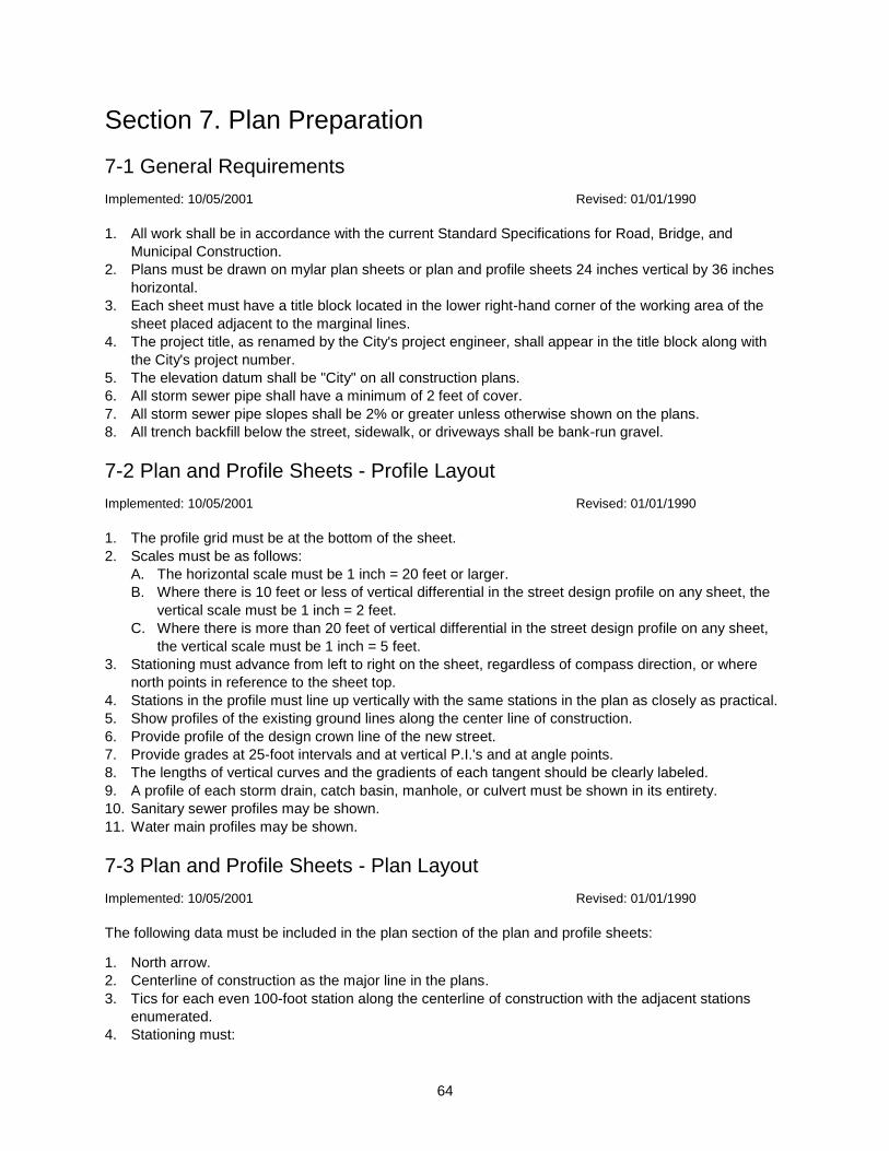
64
Section 7. Plan Preparation
7-1 General Requirements
Implemented: 10/05/2001 Revised: 01/01/1990
1. All work shall be in accordance with the current Standard Specifications for Road, Bridge, and
Municipal Construction.
2. Plans must be drawn on mylar plan sheets or plan and profile sheets 24 inches vertical by 36 inches
horizontal.
3. Each sheet must have a title block located in the lower right-hand corner of the working area of the
sheet placed adjacent to the marginal lines.
4. The project title, as renamed by the City's project engineer, shall appear in the title block along with
the City's project number.
5. The elevation datum shall be "City" on all construction plans.
6. All storm sewer pipe shall have a minimum of 2 feet of cover.
7. All storm sewer pipe slopes shall be 2% or greater unless otherwise shown on the plans.
8. All trench backfill below the street, sidewalk, or driveways shall be bank-run gravel.
7-2 Plan and Profile Sheets - Profile Layout
Implemented: 10/05/2001 Revised: 01/01/1990
1. The profile grid must be at the bottom of the sheet.
2. Scales must be as follows:
A. The horizontal scale must be 1 inch = 20 feet or larger.
B. Where there is 10 feet or less of vertical differential in the street design profile on any sheet, the
vertical scale must be 1 inch = 2 feet.
C. Where there is more than 20 feet of vertical differential in the street design profile on any sheet,
the vertical scale must be 1 inch = 5 feet.
3. Stationing must advance from left to right on the sheet, regardless of compass direction, or where
north points in reference to the sheet top.
4. Stations in the profile must line up vertically with the same stations in the plan as closely as practical.
5. Show profiles of the existing ground lines along the center line of construction.
6. Provide profile of the design crown line of the new street.
7. Provide grades at 25-foot intervals and at vertical P.I.'s and at angle points.
8. The lengths of vertical curves and the gradients of each tangent should be clearly labeled.
9. A profile of each storm drain, catch basin, manhole, or culvert must be shown in its entirety.
10. Sanitary sewer profiles may be shown.
11. Water main profiles may be shown.
7-3 Plan and Profile Sheets - Plan Layout
Implemented: 10/05/2001 Revised: 01/01/1990
The following data must be included in the plan section of the plan and profile sheets:
1. North arrow.
2. Centerline of construction as the major line in the plans.
3. Tics for each even 100-foot station along the centerline of construction with the adjacent stations
enumerated.
4. Stationing must:
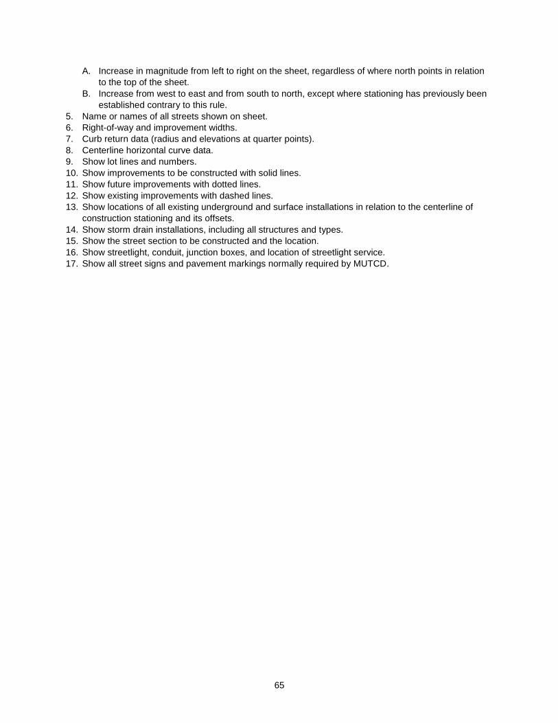
65
A. Increase in magnitude from left to right on the sheet, regardless of where north points in relation
to the top of the sheet.
B. Increase from west to east and from south to north, except where stationing has previously been
established contrary to this rule.
5. Name or names of all streets shown on sheet.
6. Right-of-way and improvement widths.
7. Curb return data (radius and elevations at quarter points).
8. Centerline horizontal curve data.
9. Show lot lines and numbers.
10. Show improvements to be constructed with solid lines.
11. Show future improvements with dotted lines.
12. Show existing improvements with dashed lines.
13. Show locations of all existing underground and surface installations in relation to the centerline of
construction stationing and its offsets.
14. Show storm drain installations, including all structures and types.
15. Show the street section to be constructed and the location.
16. Show streetlight, conduit, junction boxes, and location of streetlight service.
17. Show all street signs and pavement markings normally required by MUTCD.
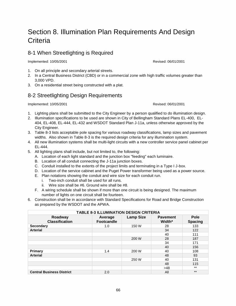
66
Section 8. Illumination Plan Requirements And Design
Criteria
8-1 When Streetlighting is Required
Implemented: 10/05/2001 Revised: 06/01/2001
1. On all principle and secondary arterial streets.
2. In a Central Business District (CBD) or in a commercial zone with high traffic volumes greater than
3,000 VPD.
3. On a residential street being constructed with a plat.
8-2 Streetlighting Design Requirements
Implemented: 10/05/2001 Revised: 06/01/2001
1. Lighting plans shall be submitted to the City Engineer by a person qualified to do illumination design.
2. Illumination specifications to be used are shown in City of Bellingham Standard Plans EL-400, EL-
404, EL-408, EL-444, EL-432 and WSDOT Standard Plan J-11a, unless otherwise approved by the
City Engineer.
3. Table 8-3 lists acceptable pole spacing for various roadway classifications, lamp sizes and pavement
widths. Also shown in Table 8-3 is the required design criteria for any illumination system.
4. All new illumination systems shall be multi-light circuits with a new controller service panel cabinet per
EL-444.
5. All lighting plans shall include, but not limited to, the following:
A. Location of each light standard and the junction box "feeding" each luminaire.
B. Location of all conduit connecting the J-11a junction boxes.
C. Conduit installed to the extents of the project limits and terminating in a Type I J-box.
D. Location of the service cabinet and the Puget Power transformer being used as a power source.
E. Plan notations showing the conduit and wire size for each conduit run.
i. Two-inch conduit shall be used for all runs.
ii. Wire size shall be #6. Ground wire shall be #8.
F. A wiring schedule shall be shown if more than one circuit is being designed. The maximum
number of lights on one circuit shall be fourteen.
6. Construction shall be in accordance with Standard Specifications for Road and Bridge Construction
as prepared by the WSDOT and the APWA.
TABLE 8-3 ILLUMINATION DESIGN CRITERIA
Roadway Classification
Average Footcandle
Lamp Size Pavement Width*
Pole Spacing
Secondary 1.0 150 W 28 133
Arterial 34 122
40 111
200 W 28 187
34 171
40 156
Primary 1.4 200 W 40 108
Arterial 48 93
250 W 40 131
48 115
>48 **
Central Business District 2.0 All **
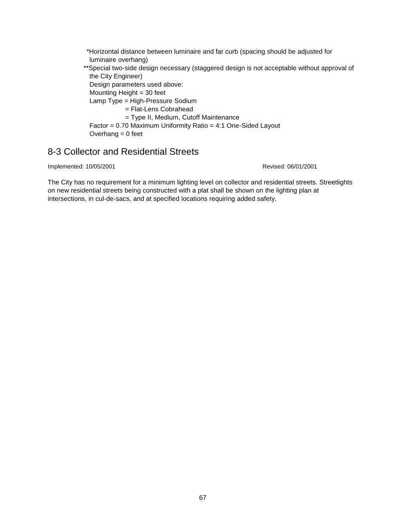
67
*Horizontal distance between luminaire and far curb (spacing should be adjusted for
luminaire overhang)
**Special two-side design necessary (staggered design is not acceptable without approval of
the City Engineer)
Design parameters used above:
Mounting Height = 30 feet
Lamp Type = High-Pressure Sodium
= Flat-Lens Cobrahead
= Type II, Medium, Cutoff Maintenance
Factor = 0.70 Maximum Uniformity Ratio = 4:1 One-Sided Layout
Overhang = 0 feet
8-3 Collector and Residential Streets
Implemented: 10/05/2001 Revised: 06/01/2001
The City has no requirement for a minimum lighting level on collector and residential streets. Streetlights
on new residential streets being constructed with a plat shall be shown on the lighting plan at
intersections, in cul-de-sacs, and at specified locations requiring added safety.
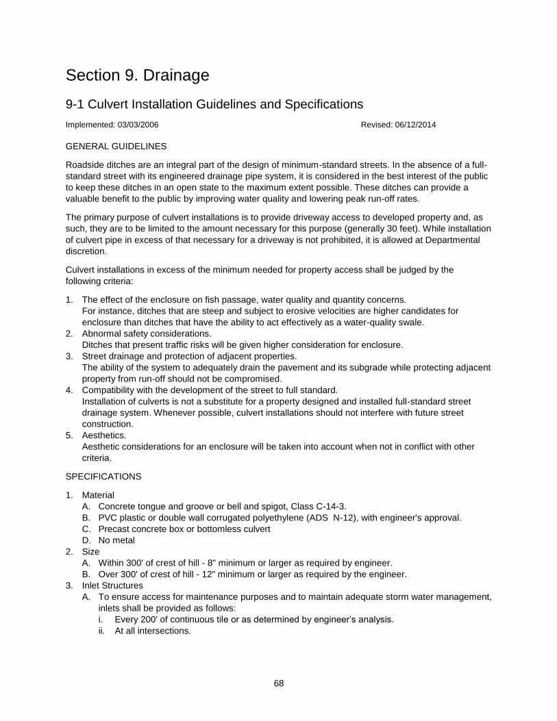
68
Section 9. Drainage
9-1 Culvert Installation Guidelines and Specifications
Implemented: 03/03/2006 Revised: 06/12/2014
GENERAL GUIDELINES
Roadside ditches are an integral part of the design of minimum-standard streets. In the absence of a full-
standard street with its engineered drainage pipe system, it is considered in the best interest of the public
to keep these ditches in an open state to the maximum extent possible. These ditches can provide a
valuable benefit to the public by improving water quality and lowering peak run-off rates.
The primary purpose of culvert installations is to provide driveway access to developed property and, as
such, they are to be limited to the amount necessary for this purpose (generally 30 feet). While installation
of culvert pipe in excess of that necessary for a driveway is not prohibited, it is allowed at Departmental
discretion.
Culvert installations in excess of the minimum needed for property access shall be judged by the
following criteria:
1. The effect of the enclosure on fish passage, water quality and quantity concerns.
For instance, ditches that are steep and subject to erosive velocities are higher candidates for
enclosure than ditches that have the ability to act effectively as a water-quality swale.
2. Abnormal safety considerations.
Ditches that present traffic risks will be given higher consideration for enclosure.
3. Street drainage and protection of adjacent properties.
The ability of the system to adequately drain the pavement and its subgrade while protecting adjacent
property from run-off should not be compromised.
4. Compatibility with the development of the street to full standard.
Installation of culverts is not a substitute for a property designed and installed full-standard street
drainage system. Whenever possible, culvert installations should not interfere with future street
construction.
5. Aesthetics.
Aesthetic considerations for an enclosure will be taken into account when not in conflict with other
criteria.
SPECIFICATIONS
1. Material
A. Concrete tongue and groove or bell and spigot, Class C-14-3.
B. PVC plastic or double wall corrugated polyethylene (ADS N-12), with engineer's approval.
C. Precast concrete box or bottomless culvert
D. No metal
2. Size
A. Within 300' of crest of hill - 8" minimum or larger as required by engineer.
B. Over 300' of crest of hill - 12" minimum or larger as required by the engineer.
3. Inlet Structures
A. To ensure access for maintenance purposes and to maintain adequate storm water management,
inlets shall be provided as follows:
i. Every 200' of continuous tile or as determined by engineer’s analysis.
ii. At all intersections.

69
iii. At junctions of dissimilar materials (PVC, concrete, metal) Alternate joining methods must be
submitted to and approved by the City Engineer or a designee. An asbuilt of the pipe change
shall be provided.
iv. At junctions of dissimilar pipe sizes.
v. At changes in horizontal or vertical alignment.
vi. As required by the engineer.
B. Inlet Design
i. WSDOT Type 1 or 2 as specified by the City Engineer.
ii. Equivalent alternative structure as approved by the City Engineer.
4. Installation
A. Bedding
i. Remove sod.
ii. Bedding material and installation shall be per City of Bellingham or the pipe manufacturer's
specifications.
B. Alignment
i. Straight horizontal.
ii. Vertical - on grade with flow line of existing ditch or upstream and downstream tile where
properly installed.
iii. Install and align as not to create ponding at either end.
iv. Where substantial ditch realignment is necessary to properly accommodate a new
installation, said realignment in front of applicant’s property shall be accomplished by the
applicant at the time of the tile installation. All other realignment will be scheduled to be
accomplished by City forces.
C. Length
i. Minimum of 18 feet for driveway. Maximum of 30 feet without specific approval by Public
Works (see General Guidelines).
ii. Any ditch gap of 10 inches or less to be tiled.
iii. Culvert installations in excess of 100 feet in length (when allowed) may require submission of
a plan and profile.
D. Backfill
i. Minimum of 12 inches of granular material over the pipe meeting the City of Bellingham’s and
WSDOT materials and compaction standards.
ii. Areas around exposed pipe ends to be covered with riprap mortared in place. The ditch end
slope at the pipe ends shall not exceed 2 horizontal to 1 vertical unless a cemented headwall
is provided.
iii. It is desirable to obtain 2 feet of pipe coverage with backfill. Any culvert subject to vehicular
traffic shall have a minimum of 12 inches of cover.
iv. Backfill shall be placed so that a minimum of 2% slope will be maintained away from the edge
of pavement.
E. Permits and Inspection
i. Public Works permit required prior to installation.
ii. Call for inspection prior to backfilling and when installation is complete (360 778-7900).
iii. Installation of culverts shall be by a licensed contractor bonded with the City of Bellingham for
performing work within the right-of-way. At departmental discretion, small installations may be
performed by the proponent with a Guarantee Deposit with the City’s Finance Department.
Silt Fence Installation
Maximum sheet or overland flow path length to the fence of 100 feet.
No flows greater than 0.5 cfs.
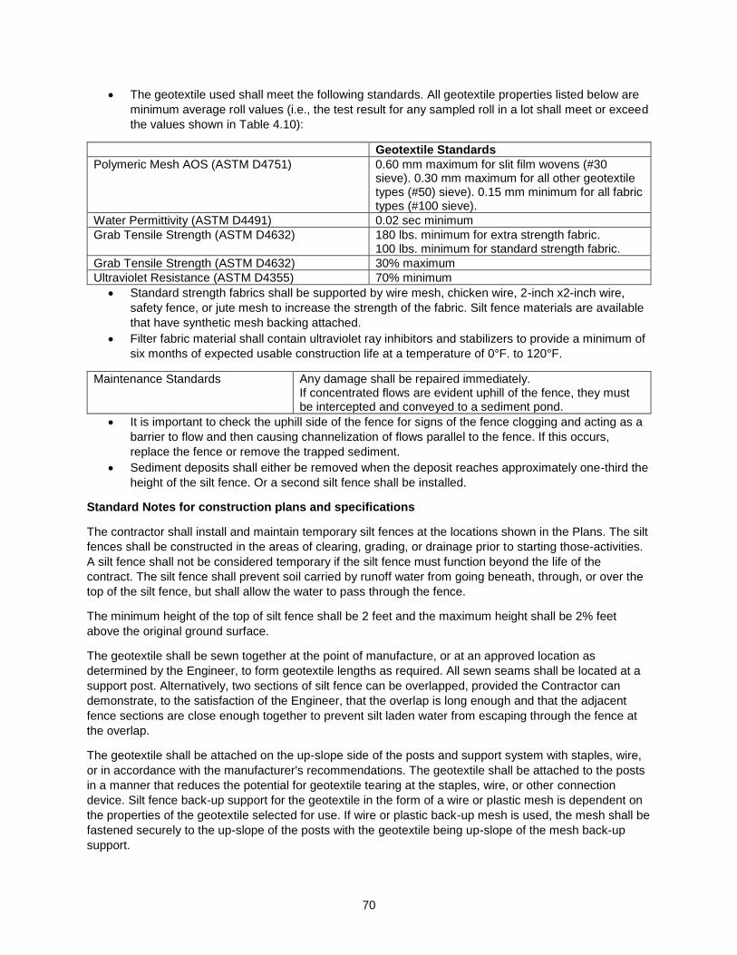
70
The geotextile used shall meet the following standards. All geotextile properties listed below are
minimum average roll values (i.e., the test result for any sampled roll in a lot shall meet or exceed
the values shown in Table 4.10):
Geotextile Standards
Polymeric Mesh AOS (ASTM D4751) 0.60 mm maximum for slit film wovens (#30 sieve). 0.30 mm maximum for all other geotextile types (#50) sieve). 0.15 mm minimum for all fabric types (#100 sieve).
Water Permittivity (ASTM D4491) 0.02 sec minimum
Grab Tensile Strength (ASTM D4632) 180 lbs. minimum for extra strength fabric. 100 lbs. minimum for standard strength fabric.
Grab Tensile Strength (ASTM D4632) 30% maximum
Ultraviolet Resistance (ASTM D4355) 70% minimum
Standard strength fabrics shall be supported by wire mesh, chicken wire, 2-inch x2-inch wire,
safety fence, or jute mesh to increase the strength of the fabric. Silt fence materials are available
that have synthetic mesh backing attached.
Filter fabric material shall contain ultraviolet ray inhibitors and stabilizers to provide a minimum of
six months of expected usable construction life at a temperature of 0°F. to 120°F.
Maintenance Standards Any damage shall be repaired immediately. If concentrated flows are evident uphill of the fence, they must be intercepted and conveyed to a sediment pond.
It is important to check the uphill side of the fence for signs of the fence clogging and acting as a
barrier to flow and then causing channelization of flows parallel to the fence. If this occurs,
replace the fence or remove the trapped sediment.
Sediment deposits shall either be removed when the deposit reaches approximately one-third the
height of the silt fence. Or a second silt fence shall be installed.
Standard Notes for construction plans and specifications
The contractor shall install and maintain temporary silt fences at the locations shown in the Plans. The silt
fences shall be constructed in the areas of clearing, grading, or drainage prior to starting those-activities.
A silt fence shall not be considered temporary if the silt fence must function beyond the life of the
contract. The silt fence shall prevent soil carried by runoff water from going beneath, through, or over the
top of the silt fence, but shall allow the water to pass through the fence.
The minimum height of the top of silt fence shall be 2 feet and the maximum height shall be 2% feet
above the original ground surface.
The geotextile shall be sewn together at the point of manufacture, or at an approved location as
determined by the Engineer, to form geotextile lengths as required. All sewn seams shall be located at a
support post. Alternatively, two sections of silt fence can be overlapped, provided the Contractor can
demonstrate, to the satisfaction of the Engineer, that the overlap is long enough and that the adjacent
fence sections are close enough together to prevent silt laden water from escaping through the fence at
the overlap.
The geotextile shall be attached on the up-slope side of the posts and support system with staples, wire,
or in accordance with the manufacturer's recommendations. The geotextile shall be attached to the posts
in a manner that reduces the potential for geotextile tearing at the staples, wire, or other connection
device. Silt fence back-up support for the geotextile in the form of a wire or plastic mesh is dependent on
the properties of the geotextile selected for use. If wire or plastic back-up mesh is used, the mesh shall be
fastened securely to the up-slope of the posts with the geotextile being up-slope of the mesh back-up
support.
71
The geotextile at the bottom of the fence shall be buried in a trench to a minimum depth of 4 inches below
the ground surface. The trench shall he backfilled and the soil tamped in place over the buried portion of
the geotextile, such that no flow can pass beneath the fence and scouring cannot occur. When wire or
polymeric back-up support mesh is used, the wire or polymeric mesh shall extend into the trench a
minimum of 3 inches.
The fence posts shall be placed or driven a minimum of 18 inches. A minimum depth of 12 inches is
allowed if topsoil or other soft subgrade soil is not present and a minimum depth of 18 inches cannot be
reached. Fence post depths shall he increased by 6 inches if the fence is located on slopes of 3:l or
steeper and the slope is perpendicular to the fence. If required post depths cannot he obtained, the posts
shall be adequately secured by bracing or guying to prevent overturning of the fence due to sediment
loading.
Silt fences shall be located on contour as much as possible, except at the ends of the fence, where the
fence shall be turned uphill such that the silt fence captures the runoff water and prevents water from
flowing around the end of the fence.
If the fence must cross contours, with the exception of the ends of the fence, gravel check dams placed
perpendicular to the back of the fence shall be used to minimize concentrated flow and erosion along the
back of the fence. The gravel check dams shall be approximately 1-foot deep at the back of the fence. It
shall be continued perpendicular to the fence at the same elevation until the top of the check dam
intercepts the ground surface behind the fence. The gravel check dams shall consist of crushed surfacing
base course, gravel backfill for walls, or shoulder ballast. The gravel check dams shall be located every
10 feet along the fence where the fence must cross contours. The slope of the fence line where contours
must be crossed shall not he steeper than 3:1.
9-2 Floodplain Development
Implemented: 10/05/2001 Revised: 01/01/1990
City of Bellingham Ordinances 9136 and 9740 establish the floodplain management standards upon
which this section is based. Floodplains and designated floodways are as indicated on the Federal
Emergency Management Agency (FEMA) generated flood boundary maps which are available for
inspection in the Engineering Division office.
The following definitions apply:
"Base Flood" means the flood having a one percent chance of being equaled or exceeded in any given
year.
"Floodway" means the channel of a river or other water course and the adjacent land areas that must be
reserved in order to discharge the base flood without cumulatively increasing the water surface elevation
more than one foot.
"Floodway Fringe" means the area in the floodplain excluding the floodway.
Land alteration within a designated floodway is prohibited unless certified by a registered professional
engineer that encroachments shall not result in any increase in flood levels during the occurrence of the
base flood discharge. To assure the City's continued participation in the National Flood Insurance
Program, the express written approval of the certified plans by FEMA is required for issuance of permits.
Construction and substantial improvement within the floodway fringe shall meet the requirements of the
floodplain ordinances. A floodplain supplement to the building permit is required in which a registered
engineer or architect certifies that the ordinance provisions have been met. The provisions are as follows.
72
9-2.01 General Standards
Implemented: 10/05/2001 Revised: 01/01/1990
In all areas of special flood hazards the following standards are required
9-2.01.01 Anchoring
Implemented: 11/16/2001 Revised: 01/01/1990
All new construction and substantial improvement shall be anchored to prevent flotation, collapse, or
lateral movement of the structure.
All occupied manufactured homes shall be anchored to resist flotation, collapse, or lateral movement by
providing over-the-top and frame ties to ground anchors. Specific requirements shall be that:
Over-the-top ties be provided at each of the four corners of the manufactured home, with two additional
ties per side at intermediate locations, with manufactured homes less than 50 feet long requiring one
additional tie per side;
Frame ties be provided at each corner of the home with five additional ties per side at intermediate points,
with manufactured homes less than 50 feet long requiring four additional ties per side;
All components of the anchoring system be capable of carrying a force of 4,800 pounds; and,
Any additions to the manufactured home be similarly anchored.
An alternative method of anchoring may utilize a system designed to withstand a wind force of 90 miles
per hour or greater. Certification must be provided to the Public Works Director that this standard has
been met.
9-2.01.02 Construction Materials and Methods
Implemented: 11/16/2001 Revised: 01/01/1990
All new construction and substantial improvements shall be completed with materials and utility
equipment resistant to flood damage.
All new construction and substantial improvements shall be completed using methods and practices that
minimize flood damage.
Electrical, heating, ventilation, plumbing and air conditioning equipment and other service facilities shall
be designed and/or otherwise elevated or located so as to prevent water from entering or accumulating
within the components during conditions of flooding.
9-2.01.03 Utilities
Implemented: 11/16/2001 Revised: 01/01/1990
All new and replacement water supply systems shall be designed to minimize or eliminate infiltration of
flood waters into the system. New and replacement sanitary sewage systems shall be designed to
minimize or eliminate infiltration of flood waters into the systems and discharge from the systems into
flood waters. On-site waste disposal systems shall be located to avoid impairment to them or
contamination from them during flooding.
73
9-2.01.04 Subdivision Proposals
Implemented: 11/16/2001 Revised: 01/01/1990
All subdivision proposals shall be consistent with the need to minimize flood damage, and shall have
public utilities and facilities such as sewer, gas, electrical and water systems located and constructed to
minimize flood damage. All subdivision proposals shall have adequate drainage provided to reduce
exposure to flood damage, and base flood elevation data shall be provided for subdivision proposals and
other proposed development which contain at least 50 lots or 5 acres (whichever is less).
9-2.01.05 Encroachments
Implemented: 11/16/2001 Revised: 01/01/1990
Any proposed development shall be analyzed to determine effects on the flood-carrying capacity of the
area of special flood hazard.
9-2.02 Specific Standards
Implemented: 10/05/2001 Revised: 01/01/1990
In all areas of special flood hazard where base flood elevation data has been provided, the following
standards are required.
9-2.02.01 Residential Construction
Implemented: 11/16/2001 Revised: 01/01/1990
New construction and substantial improvement of any residential structure shall have the lowest habitable
floor, including basement, elevated to at least one foot above the base flood elevation. The long axis of
the foundation must be aligned with the flood flow.
Fully-enclosed areas below the lowest floor that are subject to flooding are prohibited, or shall be
designed to automatically equalize hydrostatic flood forces on exterior walls by allowing for the entry and
exit of floodwaters. Designs for meeting this requirement must either be certified by a registered
professional engineer or architect or must meet or exceed the following minimum criteria:
A minimum of two openings having a total net area of not less than one square inch for every square foot
of enclosed area subject to flooding shall be provided.
The bottom of all openings shall be no higher than one foot above grade.
Openings may be equipped with screens, louvers, or other coverings or devices provided that they permit
the automatic entry and exit of floodwaters.
9-2.02.02 Nonresidential Construction
Implemented: 11/16/2001 Revised: 01/01/1990
New construction and substantial improvement of any commercial, industrial or other nonresidential
structure shall either have the lowest habitable floor, including basement, elevated to at least one foot
above the base flood elevation, or, together with attendant utility and sanitary facilities, shall:
Have the long axis of the foundation aligned with the flood flow;
74
Be floodproofed so that below the base flood level, the structure is watertight with walls substantially
impermeable to the passage of water;
Have structural components capable of resisting hydrostatic and hydrodynamic loads and effects of
buoyancy; and
Be certified by a registered professional engineer or architect that the standards of this subsection are
satisfied.
Additionally, nonresidential structures that are elevated, not floodproofed, must meet the same standards
for space below the lowest floor as for residential structures.
9-2.02.03 Manufactured Homes
Implemented: 11/16/2001 Revised: 01/01/1995
Manufactured homes shall be anchored in accordance with the previous Section 9-2.01.1.
For new manufactured homes in appropriately-approved residential-multi planned areas and
manufactured home subdivisions, for expansions to existing manufactured home subdivisions, for existing
residential-multi planned areas which include manufactured homes not placed in a manufactured home
subdivision, it is required that:
Stands or lots are elevated on compacted fill or on pilings so that the lowest floor of the manufactured
home will be at least one foot above the base flood level;
Adequate surface drainage and access for a hauler are provided; and,
In the instance of elevation on pilings, that lots are large enough to permit steps, piling foundations are
placed in stable soil no more than ten feet apart, and reinforcement is provided for pilings more than 6
feet above the ground level.
No manufactured home shall be placed in a floodway, except in an existing manufactured home park or
existing manufactured home subdivision.
75
Section 10. Local Improvement District Process
10-1 Introduction
Implemented: 10/05/2001 Revised: 01/01/1990
The Local Improvement District (LID) is a method by which property owners within a defined geographical
area can make an improvement benefiting their property. Improvements financed by the LID can include
street and sidewalk construction, water mains, sanitary sewer and storm drains. Assessments are usually
determined by the size and location of each property in relation to the improvement and the
benefit to the property.
10-2 Procedure
Implemented: 10/05/2001 Revised: 01/01/1990
The LID may be initiated by City Council resolution or by petition of the majority of property owners along
the frontage of the improvement within the proposed boundaries of the district.
City Engineering Staff will assist the property owners interested in creating an LID in preparing the
petition and will be available to answer questions or meet with neighborhood groups.
10-3 Steps
Implemented: 10/05/2001 Revised: 01/01/1990
The following steps will outline the procedure that will be followed after the petition has been accepted or
the resolution has been passed.
1. The City Council will call for a public hearing and instruct the City Engineer to:
A. Estimate the cost of the improvement.
B. Prepare a drawing defining the boundaries of the LID.
C. Determine the preliminary assessment (to be a viable project, the sum of the preliminary
assessments cannot exceed the true value of the property to be assessed, plus one quarter of
the value of the improvements located on that property).
2. The City Council will:
A. Determine the assessment formula (rate per square foot, rate per front foot, zone and termini,
etc.) which considers the benefit to each property.
B. Direct Staff to mail to each affected property owner a notice of the date for public hearing and the
amount of preliminary assessment, and advertise the notice in two consecutive issues of the
newspaper at least fifteen days before the hearing.
3. The project is explained by Staff at the public hearing and testimony is heard by the Council. If a
majority of the Council votes to accept the LID ordinance, Staff is directed to publish the ordinance.
4. Once published, a 30-day protest period begins (an improvement judged necessary for public health
and safety may not be challenged but requires the unanimous vote of all Councilmembers present).
Property owners that comprise sixty percent or more of the total preliminary assessments may stop
the LID by filing a written protest with the City Clerk within the thirty day period.
5. The LID project surviving the protest period is:
A. Designed by the City's Engineering Division.
B. Advertised for competitive bidding. The construction contract is awarded to the lowest responsible
bidder after Engineering Staff review. If final costs are projected to exceed the preliminary
estimate by more than ten percent, the project is reconsidered.
76
C. Finalized by compiling all costs associated with the project and preparing a final assessment roll.
Costs will include administration, design, construction, appraisal services, right-of-way and
interest on warrants issued by the City to provide payment for work in progress until bonds are
sold.
6. The notice of the hearing on the final assessment is:
A. Mailed to all property owners within the LID district at least 15 days before the hearing.
Advertised five times in a daily newspaper or twice in a weekly publication at least 15 days before
the hearing.
7. The City Council holds the assessment roll hearing. Modifications to the assessment roll may only be
made at this time, unless a mistake or omission is discovered later. Once passed and published,
appeals may only be directed to the Superior Court within ten days of the LID ordinance publication.
8. The City Clerk publishes notice of the assessment in the official newspaper once a week for two
weeks and mails collection notices to all property owners. Interest-free payment may be made within
30 days of published notice (the prepayment period). Payment installments are due one year from the
expiration date of the 30-day prepayment period.
9. Minimum time needed to complete a project utilizing the LID process is approximately 10 months
from the time the petition is accepted and the resolution is adopted.

77
Section 11. Traffic Studies
11-1 Responsibilities for Traffic Studies
Implemented: 10/05/2001 Revised: 01/01/1990
Traffic studies may be required by the City in order to adequately assess the impacts of a development
proposal on the existing and/or planned street system. This would typically be provided in the traffic
circulation section of an EIS. The primary responsibility for assessing the traffic impacts associated with a
proposed development will rest with the developer, with the City serving in a review capacity and, upon
approval, accepting the assessments made as its own.
Unless waived by the City, a written study meeting the City criteria will be required for a development
proposal when trip generation during any peak hour is expected to exceed 50 vehicles or the criteria
provided in Appendix 1.
Developments within 10% of these criteria may, at the discretion of the Public Works Department, be
required to provide a traffic study. If they are more than 10% below the criteria, a traffic study should not
be required unless there are special extenuating circumstances such as safety concerns over access,
neighborhood opposition to the project or existing levels of service on area roads are at "D", "E", or "F."
Levels of service are defined in Subsection 11-2.06.
An applicant must submit a traffic study as part of any environmental review process, as part of any
application as listed below, or obtain a determination from the City that a traffic study will not be required.
Such a study may be required prior to deeming a project complete for processing.
This study will be the responsibility of the applicant and must be prepared by a registered professional
traffic or civil engineer with adequate experience in transportation engineering.
Upon submittal of a draft traffic study, the Public Works Department and the Planning and Economic
Development Department will review the study data sources, methods, and findings.
Comments will be provided in a written form to the Planning and Economic Development Department.
The developer and the private engineer will then have an opportunity to incorporate necessary revisions
prior to submitting a final report.
Due to the time lines involved in processing an application, a report may be required prior to deeming a
project submitted as complete. Generally, draft reports should be completed for review and comment
within 40 calendar days after notice to proceed.
Final reports should be completed and submitted within 14 days after Staff comments on the draft are
returned to the consultant.
The findings of all approved traffic studies will be summarized and forwarded to the Planning and
Economic Development Department by the Public Works Department.
The following applications will require traffic studies prepared in the format required by the Public Works
Department as part of the submittal materials for a development project submitted to be deemed
complete unless waived by the City:
1. Any application for which the proposed development exceeds the criteria for requiring traffic studies
provided in Appendix 1.
2. Additional access off a state highway or a city road to an existing project which exceeds the criteria in
Appendix 1.
78
3. A change of use affecting access from a state highway or a city road for a project exceeding the
criteria in Appendix 1.
4. Any application, which is located in an area where existing levels of service on area roads, are "D",
"E" or "F."
The applicant will be required to submit a new traffic study if, after submitting an original traffic study for
any of the above applications, the land use intensity is increased or the land use is changed so that trip
generation is increased and existing levels of service on area roads are at "D", "E", or "F."
All previous traffic studies relating to the development that are more than 2 years old will have to be
updated unless the Planning and Economic Development Department and Public Works Department
determines that conditions have not changed significantly.
Where access points are not defined at the time the traffic study is prepared, additional traffic work may
be required when the access points are defined.
Transportation consultants are required to discuss projects with the Engineering Division of the Public
Works Department and the Division of Environmental Review of the Planning and Economic
Development Department prior to starting the study.
As a minimum, topics for possible discussion will include trip generation, directional distribution of traffic,
trip assignment, definition of the study area, intersections requiring critical lane analysis, and methods of
projecting build-out volume of cumulative projects. This will provide a firm base of cooperation and
communication between the City, the owner or developer, and the project's consultants in forecasting
future traffic characteristics, which realistically define traffic movement associated with the proposed
development.
Specific requirements will vary depending on the site location.
No traffic study will be accepted unless the traffic study requirements form provided in Appendix 4 is filled
out by the consultant and approved by the Public Works Department, prior to the consultant preparing the
traffic study.
All completed traffic studies that have been reviewed and approved by the Public Works Department will
become the joint property of the project and the City of Bellingham.
11-2 Traffic Study Format
Implemented: 10/05/2001 Revised: 06/01/1996
In order to provide consistency and to facilitate Staff review of traffic studies, the following format must be
followed in the preparation of such studies by transportation consultants.
A summary outline is provided in Appendix 2.
11-2.01 Introduction
Implemented: 10/05/2001 Revised: 06/01/1996
The introduction portion of the report must contain the following:
1. Land Use, Site and Study Area Boundaries
A brief description of the size of the land parcel, general terrain features, the location within the
jurisdiction, and the region must be included in this section. In addition, the roadways that afford
access to the site and are included in the study area must be identified.
79
The exact limits of the study area should be based on engineering judgment, and an understanding of
existing traffic conditions surrounding the site. In all instances, however, the study area limits must be
mutually agreed upon by the developer, their engineer, the Planning and Economic Development
Department, the Public Works Department, and justified in the report. These limits will usually result
from initial discussions with the City. A vicinity map that shows the site and the study area
boundaries, in relation to the surrounding transportation system, must be included.
2. Existing and Proposed Site Uses
The existing and proposed uses of the site must be identified in terms of the various zoning
categories of the City. In addition, the specific use for which the request is being made must be
identified, if known, since a number of uses may be permitted under the existing ordinances.
This information should include the square footage of the various uses or the number and size of the
units proposed.
It will be the intent of the traffic study to evaluate the worst-case traffic impacts for the proposed
development allowed by the zoning. If several different uses are permitted by the zoning, the land use
with the greatest overall traffic impact must be assumed for the study.
3. Existing and Proposed Uses in Vicinity of Site
A complete description of all unbuilt but approved projects, projects in process, and projects with pre-
applications within the study area, and their approved future uses must be provided.
If approved uses are not available, a City-approved estimate of the probable future uses based on
zoning designations should be provided. This latter item is especially important where large tracts of
undeveloped land are in the vicinity of the site and within the prescribed study area.
A list of unbuilt but approved projects, projects in process and projects with pre-applications
submitted must be obtained from the Planning and Economic Development Department. One
hundred percent occupancy must be assumed for all developments in the cumulative analysis.
4. Existing and Proposed Roadways and Intersections
Within the study area, the applicant must describe and provide volumes for existing roadways and
intersections including geometric and traffic signal control as well as improvements that have been
funded by government agencies and other development projects. An official list of funded projects
must be obtained from the City. This would include the nature of the improvement project, its extent,
implementation schedule, and the agency or funding source responsible. A map must be provided
showing the location of such facilities.
11-2.02 Project Trip Generation and Design -Hour Volumes
Implemented: 10/05/2001 Revised: 01/01/1990
A summary table listing each type of land use, the size involved, the average trip-generation rates used
(total daily traffic and AM/PM peak hours of the street), and the resultant total trips generated must be
provided for the project site and all unbuilt but approved projects, projects in process, and projects with
pre-applications within the study area.

80
A current list of projects to be included in the cumulative analysis must be obtained from the Division of
Environmental Review, Planning and Economic Development Department.
Trip generation must be calculated for the maximum uses allowed under the existing and proposed
zoning based on the latest data contained within the latest edition of the Institute of Transportation
Engineer's (ITE) Trip Generation Manual or more appropriate local data as approved by the Public Works
Department.
In the event that data is not available for the proposed land use, the Public Works Department must
approve estimated rates prior to acceptance of the draft traffic study report.
The calculation of design-hour volumes used to determine study area impacts must be based on:
1. Peak-hour trip generation rates as published in the ITE Trip Generation Summary.
2. Recent traffic volume counts for an acceptable number of similar existing uses if no published rates
are available. Counts of this nature must be acceptable to the Public Works Department.
3. Additional sources from other jurisdictions, or W.S.D.O.T. if acceptable to the Public Works
Department. A list of trip generation publications has been included in the bibliography.
4. For mixed-use developments, ITE rates must be used to estimate average daily traffic. The PM peak
hour of the street may be estimated by using 9% of total daily traffic.
Use of the percentage rates (as shown in Table 11-2 in Subsection 11-2.13) to account for passerby
traffic may be considered upon approval of the Public Works Department.
Internal trip reductions and modal-split assumptions will require analytical support to demonstrate how the
figures were derived and will require approval by the Public Works Department.
See Technical Requirements in Subsection 11-2.13.
11-2.03 Trip Distribution
Implemented: 10/05/2001 Revised: 01/01/1990
The estimates of percentage distribution of trips from the proposed development to destinations, both
within and outside the City, must be clearly stated in the report using the north, south, east, and west
compass points.
Market studies, planning data, driveway counts at adjacent uses or other information concerning origin of
trip attractions to the proposed development may be used to support these assumptions where available.
A map showing the percentage of site traffic on each street based on average-daily volumes must be
provided as part of the traffic study graphic material. Where microcomputer modeling is used, such a map
need not be provided, but the model's distribution methodology must be discussed.
11-2.04 Trip Assignment
Implemented: 10/05/2001 Revised: 01/01/1990
The direction of approach of site-generated traffic via the area's street system will be presented in this
section. The technical analysis steps, basic methods, and assumptions used in this work must be clearly
stated and agreed to by the Public Works Department.
The assumed trip distribution and assignment must represent the most logically traveled route for drivers
accessing the proposed development. These routes can be determined by observation of travel patterns
to existing land uses in the study area.

81
11-2.05 Existing and Projected Traffic Volumes
Implemented: 10/05/2001 Revised: 01/01/1990
Graphics must be provided which show the following traffic impacts for private access points,
intersections and streets specified in the traffic study requirements form.
1. PM peak-hour site traffic (in and out) including turning movements.
2. PM peak-hour traffic total including site-generated traffic (in and out). These volumes must include
through- and turning-movement volumes for current conditions and a separate set of numbers that
also include all projects to be included in the cumulative analysis.
3. Any other peak hour which is determined by the City to be critical to site traffic and the road system in
the study area should be included in the graphics and show the same information as is provided for
the AM/PM peak hours (i.e., recreational and seasonal traffic).
4. Actual counts of existing total daily traffic for the road system in the study area at the time the study is
being prepared.
5. Projected total daily traffic for the road in the study area based on traffic from the proposed
development and counts of existing daily traffic obtained in Item 6. The component of the existing
daily traffic attributable to the existing uses must be identified and the increases in total daily traffic
from the proposed uses.
6. Projected total daily traffic for the street system in the study area based on traffic from the proposed
development, counts of existing daily traffic obtained in Item 4 above, and traffic projections based on
all projects to be included in the cumulative analysis. The projects to be included in the cumulative
analysis must be those specified by the Planning and Economic Development Department.
A list of current projects to be included in the cumulative analysis must be obtained from the Division of
Environmental Review.
Peak hours referred to in this section are for the street and not the generator or project.
Where necessary, volume projections for background traffic growth will be provided by the Public Works
Department, or alternatively, a method for determining the volume will be recommended.
All total daily traffic counts must be actual machine count and not based on factored peak-hour sampling.
Latest available machine counts from WSDOT, the Public Works Department, or other agencies may be
acceptable if not more than one year old.
11-2.06 Capacity Analysis
Implemented: 10/05/2001 Revised: 01/01/1990
A capacity analysis will be conducted for all public road intersections impacted by the proposed
development and for all private property access points to street adjacent to the proposed development as
specified in the traffic study requirements form and within the limits of the previously defined study area.
The PM, and any other peak period specified by the Public Works Department, will be tested to determine
which peak hours need to be analyzed.
Capacity calculations should also include an analysis for cumulative impacts.
At 4-way stop sign intersections, estimates of the delay per vehicle and queue lengths on critical
approaches must be provided.
At 2-way stop intersections, the unsignalized intersection analysis contained in the Highway Capacity
Manual must be used.
82
11-2.07 Level of Service
Implemented: 10/05/2001 Revised: 01/01/1990
Level of service "C" will be the peak-hour design objective for all movements, and under no
circumstances will less than level of service "D" be accepted for site- and non-site traffic including existing
traffic at build out of the study area.
The traffic study must recommend feasible mitigation measures to bring the intersection level of service
within acceptable standards.
The following interpretations of "level of service" have been provided:
Level of Service A A condition of free flow with low traffic density, where no vehicle waits longer
than one signal cycle.
Level of Service B A stable flow of traffic where occasionally drivers wait through more than one
signal cycle.
Level of Service C Still in the zone of stable flow, but intermittently drivers must wait through more
than one signal cycle and back-ups may develop behind left-turning vehicles.
Level of Service D Approaching instability, drivers are restricted in their freedom to change lanes
and delays for approaching vehicles may be substantial during peak hours.
Level of Service E Traffic volumes are near or at the capacity of the arterial, and long queues of
vehicles may create lengthy delays especially for left-turning vehicles.
Level of Service F Congested condition of forced traffic flow, where queued backups from locations
downstream restrict or prevent movement of vehicles out of the approach,
creating a storage area during part or all of the peak hour.
For existing conditions, levels of service should be calculated either by the operational analysis method
from the new Highway Capacity Manual or the TRB Circular 212 Method. Where available, existing levels
of service will be certified and supplied by the City.
For future conditions, levels of service should be calculated by the TRB Circular 212 Method or by any
other method satisfactorily documented by the consultant and approved by the City.
Maximum sums of critical lane volumes for determining levels of service using the Critical Lane Planning
Analysis Technique are provided in Appendix 3.
All levels of service must be provided with corresponding volume to capacity ratios.
11-2.08 Traffic Signals
Implemented: 10/05/2001 Revised: 01/01/1990
The need for new traffic signals will be based on warrants contained in the Manual on Uniform Traffic
Control Devices.
In determining the location of a new signal, traffic progression is of paramount importance.
Pedestrian movements must be considered in the evaluation, and adequate pedestrian clearance
provided in the signal cycle-split assumptions.
83
To provide flexibility for existing conditions and ensure optimum 2-way signal progression, an approved
traffic engineering analysis must be made to properly locate all proposed access that may require
signalization.
The section of roadway to be analyzed for signal progression will be determined by the Public Works
Department and will include all existing and possible future signalized intersections.
The progression pattern calculations must use a cycle consistent with current signal timing policies of the
City. A desirable bandwidth of 50% of the signal cycle must be used where existing conditions allow.
Where intersections have no signals presently, but are expected to have signals, typically a 60% main
line, 40% cross-street cycle-split should be assumed.
Cycle-split assumptions must relate to volume assumptions in the capacity analysis of individual
intersections; and where computerized progression analysis techniques are used, they must be of the
type that utilize turning movement volume data and pedestrian clearance times in the development of
time/space diagrams.
The green time allocated to the cross street will be considered no less than the time which is required for
a pedestrian to clear the main street using the Manual on Uniform Traffic Control Devices standards.
Those intersections, which would reduce the optimum bandwidth if a traffic signal were installed, may be
required to remain unsignalized and have turning movements limited by access design or median islands.
11-2.09 Traffic Accidents
Implemented: 10/05/2001 Revised: 01/01/1990
Traffic accident data for affected street corridors may be required for the study. The study period will
normally be three years. Such locations will be specified by the Public Works Department and data
provided by the City.
Where account data is required, estimates of increased or decreased accident potential must be
evaluated for the development, particularly if the proposed development might impact existing traffic
safety problems in the study area. Safety improvements shall be recommended where necessary.
11-2.10 Recommendations
Implemented: 10/05/2001 Revised: 01/01/1990
In the event that analysis indicates unsatisfactory levels of service ("D" or below) on study area roadways,
a description of proposed improvements to return intersections to level of service "C" must be included.
Proposals could include projects by the City or State for which funds have been appropriated and
obligated.
The assumptions regarding all future roads and lanes in an analysis will require approval from the City. In
general, the recommendation section should include:
1. Proposed Recommended Improvement
This section must describe the location, nature, and extent of proposed improvements to ensure
sufficient roadway capacity.
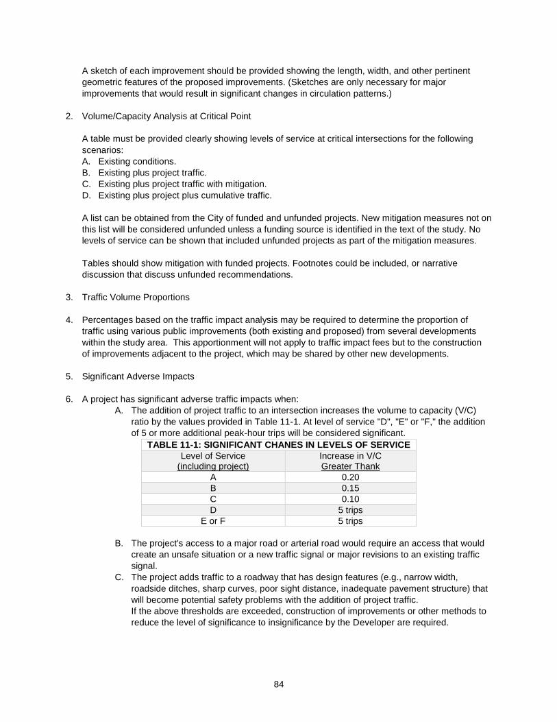
84
A sketch of each improvement should be provided showing the length, width, and other pertinent
geometric features of the proposed improvements. (Sketches are only necessary for major
improvements that would result in significant changes in circulation patterns.)
2. Volume/Capacity Analysis at Critical Point
A table must be provided clearly showing levels of service at critical intersections for the following
scenarios:
A. Existing conditions.
B. Existing plus project traffic.
C. Existing plus project traffic with mitigation.
D. Existing plus project plus cumulative traffic.
A list can be obtained from the City of funded and unfunded projects. New mitigation measures not on
this list will be considered unfunded unless a funding source is identified in the text of the study. No
levels of service can be shown that included unfunded projects as part of the mitigation measures.
Tables should show mitigation with funded projects. Footnotes could be included, or narrative
discussion that discuss unfunded recommendations.
3. Traffic Volume Proportions
4. Percentages based on the traffic impact analysis may be required to determine the proportion of
traffic using various public improvements (both existing and proposed) from several developments
within the study area. This apportionment will not apply to traffic impact fees but to the construction
of improvements adjacent to the project, which may be shared by other new developments.
5. Significant Adverse Impacts
6. A project has significant adverse traffic impacts when:
A. The addition of project traffic to an intersection increases the volume to capacity (V/C)
ratio by the values provided in Table 11-1. At level of service "D", "E" or "F," the addition
of 5 or more additional peak-hour trips will be considered significant.
TABLE 11-1: SIGNIFICANT CHANES IN LEVELS OF SERVICE
Level of Service (including project)
Increase in V/C Greater Thank
A 0.20
B 0.15
C 0.10
D 5 trips
E or F 5 trips
B. The project's access to a major road or arterial road would require an access that would
create an unsafe situation or a new traffic signal or major revisions to an existing traffic
signal.
C. The project adds traffic to a roadway that has design features (e.g., narrow width,
roadside ditches, sharp curves, poor sight distance, inadequate pavement structure) that
will become potential safety problems with the addition of project traffic.
If the above thresholds are exceeded, construction of improvements or other methods to
reduce the level of significance to insignificance by the Developer are required.
85
11-2.11 Revisions to Traffic Study
Implemented: 10/08/2001 Revised: 01/01/1990
Revisions to the traffic study must be provided as required by the City. The City will determine whether
revisions are necessary.
The need for revisions will be based on the completeness of the traffic study, the thoroughness of the
impact evaluation, and the compatibility of the study with the proposed access and development plan.
11-2.12 Executive Summary
Implemented: 10/08/2001 Revised: 01/01/1990
The executive summary of the report must be a clear, concise description of the study findings. It is
anticipated that the report's final chapter will serve as an executive summary.
It must include a general description of all data, project scope and purpose, findings, conclusions, and
mitigation measures and recommendations.
Technical publications and calculations, documentation, data reporting and detail design must not be
included in this section.
The executive summary should be short, complete in itself, and not dependent on supplementary data
included by reference.
11-2.13 Technical Requirements of Final Report
Implemented: 10/08/2001 Revised: 01/01/1990
The final report must also meet the following requirements:
1. Transportation System Management (TSM) concepts must be fully explored and discussed. An
updated generalized statement offered as a solution to a specific problem is not acceptable. The
solutions offered must be backed by data to confirm practicability of successful implementation.
2. All computerized analysis output sheets and supporting raw-count data, both ADT, turning movement,
and intersection-delay data should be submitted with draft reports for review.
All assumptions used in the calculations must be referenced to the appropriate table, chart or page in
approved publication (e.g. V/C ratios, operating speeds, etc). Calculations must be comprehensive
and clear.
3. All maps and graphics involving improvements must be drawn to scale with roadway geometrics
appropriately dimensioned (e.g. road width, lane widths, etc). Intersection geometrics must include
bus stops, parking areas, pedestrian crossings, driveway restrictions, etc.
4. For employee-intensive uses, such as office buildings, trip rates may be reduced to account for the
effects of ride sharing. The text of the report must fully justify the use of any ride sharing percentage
adjustments.
5. Normally, ride-sharing reductions will not be applied to such uses as hotels, restaurants, retail,
financial, or medical related uses.
6. Daily-trip rates may be reduced for those land uses potentially served by transit. The effects of van
pooling would not be considered as a portion of "ride sharing." The use of any transit percentage
adjustments must be justified in the text of the report. The current maximum allowable transit use
assumption is 5%.
7. Normally, transit reductions would only apply to employee-intensive uses and residential uses. Uses
not expected to have transit reductions would include hotels, restaurants, retail and financial uses.
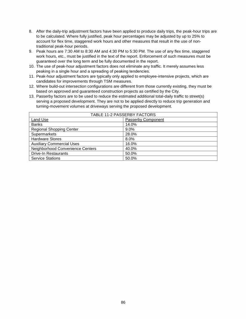
86
8. After the daily-trip adjustment factors have been applied to produce daily trips, the peak-hour trips are
to be calculated. Where fully justified, peak hour percentages may be adjusted by up to 25% to
account for flex time, staggered work hours and other measures that result in the use of non-
traditional peak-hour periods.
9. Peak hours are 7:30 AM to 8:30 AM and 4:30 PM to 5:30 PM. The use of any flex time, staggered
work hours, etc., must be justified in the text of the report. Enforcement of such measures must be
guaranteed over the long term and be fully documented in the report.
10. The use of peak-hour adjustment factors does not eliminate any traffic. It merely assumes less
peaking in a single hour and a spreading of peaking tendencies.
11. Peak-hour adjustment factors are typically only applied to employee-intensive projects, which are
candidates for improvements through TSM measures.
12. Where build-out intersection configurations are different from those currently existing, they must be
based on approved and guaranteed construction projects as certified by the City.
13. Passerby factors are to be used to reduce the estimated additional total-daily traffic to street(s)
serving a proposed development. They are not to be applied directly to reduce trip generation and
turning-movement volumes at driveways serving the proposed development.
TABLE 11-2 PASSERBY FACTORS
Land Use Passerby Component
Banks 14.0%
Regional Shopping Center 9.0%
Supermarkets 28.0%
Hardware Stores 8.0%
Auxiliary Commercial Uses 16.0%
Neighborhood Convenience Centers 40.0%
Drive-In Restaurants 50.0%
Service Stations 50.0%
87
Section 12. Access And Site Access Design
12-1 Introduction
Implemented: 10/08/2001 Revised: 01/15/1990
This section pertains to the access of private properties from the arterial street system of the City as
contained in Ordinance 8760. This is considered a summary of the ordinance and if a conflict arises, the
ordinance shall take precedence.
12-2 Definitions
Implemented: 10/08/2001 Revised: 01/15/1990
"Arterial Street" means every public highway, or portion thereof, or a major street designated as such by
ordinance, in accordance with the law of the State of Washington.
"Minor Street" means any city street not designated by competent authority as an arterial street, a state
highway, a parkway, an expressway, or a freeway.
"Driveway" means a vehicle access between abutting property and a city right-of-way or a city street.
"Residential Driveway" means one providing access to a single-family residence, to a duplex, or to an
apartment building containing not more than 4 dwellings.
"Commercial Driveway" means one providing access to an office, retail or institutional building, or to an
apartment building having 5 or more dwelling units.
"Industrial Driveway" means one directly serving substantial numbers of truck movements to and from
loading docks of an industrial facility, warehouse, truck terminal, or community or regional mall loading
area.
"Curb Return-Type Driveway" means one which is essentially a "T" intersection with constant curb cross
section from curb-return to curb-return as found at the intersection of two streets.
"Depressed-Type Driveway" means one in which the curb is depressed along the curb line per City of
Bellingham standard plans ST-9 and CG-260.
"Driveway Width" means the driveway throat distance, measured at the property line, for both depressed-
and curb-entry type driveways (see Figure 12-1).
"Parcel" means any piece of real property in a single ownership.
12-3 Permit Required
Implemented: 10/08/2001 Revised: 01/15/1990
A permit, issued by the Public Works Department on written application, is required for the construction or
reconstruction of any driveway giving access from a parcel to a street or alley.
No other permit for driveway construction or reconstruction shall be required when such a permit is
obtained. The Public Works Department shall only issue permits for driveways after that Department has
ensured that the requirements of the ordinance are complied with, that the proposed construction or
reconstruction is in accordance with standard plans and specifications, and that the proposed
construction or reconstruction is in accordance with good and accepted engineering practice.

88
12-4 Number of Driveways Permitted
Implemented: 10/08/2001 Revised: 01/01/1990
Each parcel shall be permitted one driveway giving access to an abutting arterial street, either permitting
direct access to the parcel, or jointly with an adjoining parcel. Additional driveways giving access to one
or more arterial streets shall be permitted only under the following conditions:
1. When the owner of the parcel can demonstrate that the daily volume of traffic using a single driveway
would be in excess of 5,000 one-way vehicle trips per day; or,
2. When the owner of the parcel can demonstrate that the vehicle traffic using a single driveway would
exceed the capacity of a stop sign-controlled intersection during one peak-street traffic hour, or the
peak-site traffic hour, as capacity is determined by a qualified professional engineer, and approved by
the Director of Public Works; or,
3. When the owner of the parcel can demonstrate, by a traffic engineering study, that the addition of
another driveway will benefit the flow of traffic on the abutting arterial street.
12-5 When Traffic Signals May Be Required
Implemented: 10/08/2001 Revised: 01/01/1990
The Public Works Department may require the installation of an electronic traffic signal at the cost of the
owner of a parcel to control the ingress and egress of traffic from the driveway when the parcel would
normally be allowed two or more driveways and a traffic signal(s) is warranted. A signal may be required
either at the time a driveway permit is applied for or after a traffic study demonstrates its need.
12-6 Driveway Spacing
Implemented: 10/08/2001 Revised: 01/01/1990
Driveways providing access to arterial streets shall be spaced a minimum of 200 feet apart; however, the
Public Works Department may issue a permit, which will result in lesser spacing when all of the following
factors are present:
1. The parcel does not have adequate frontage on the arterial street to provide the 200 foot spacing;
2. After good faith attempts, the owner of the parcel is unable to secure joint access through an
adjoining parcel;
3. The parcel to be served cannot be served from another street; and,
4. The resultant driveway provides maximum spacing from adjacent driveways giving access to the
arterial street, and proper corner clearance is provided. When measuring distances to or between
driveways, distance shall be measured from the edge-of-throat to edge-of-throat as shown in Figure
12-3.
12-7 Joint-Access Driveways
Implemented: 10/08/2001 Revised: 01/15/1990
The Public Works Department shall encourage and facilitate use of joint-access driveways serving two or
more adjoining parcels. Where joint-access driveways are feasible and not objected to by the owners of
the affected parcels, the Public Works Department may require:
1. Owners of parcels using the joint-access driveway to share the cost of construction or reconstruction
of the driveway;
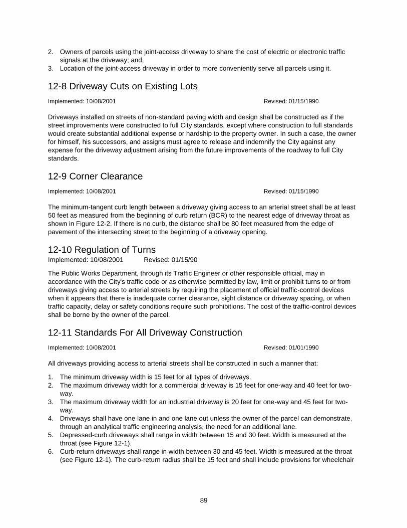
89
2. Owners of parcels using the joint-access driveway to share the cost of electric or electronic traffic
signals at the driveway; and,
3. Location of the joint-access driveway in order to more conveniently serve all parcels using it.
12-8 Driveway Cuts on Existing Lots
Implemented: 10/08/2001 Revised: 01/15/1990
Driveways installed on streets of non-standard paving width and design shall be constructed as if the
street improvements were constructed to full City standards, except where construction to full standards
would create substantial additional expense or hardship to the property owner. In such a case, the owner
for himself, his successors, and assigns must agree to release and indemnify the City against any
expense for the driveway adjustment arising from the future improvements of the roadway to full City
standards.
12-9 Corner Clearance
Implemented: 10/08/2001 Revised: 01/15/1990
The minimum-tangent curb length between a driveway giving access to an arterial street shall be at least
50 feet as measured from the beginning of curb return (BCR) to the nearest edge of driveway throat as
shown in Figure 12-2. If there is no curb, the distance shall be 80 feet measured from the edge of
pavement of the intersecting street to the beginning of a driveway opening.
12-10 Regulation of Turns Implemented: 10/08/2001 Revised: 01/15/90
The Public Works Department, through its Traffic Engineer or other responsible official, may in
accordance with the City's traffic code or as otherwise permitted by law, limit or prohibit turns to or from
driveways giving access to arterial streets by requiring the placement of official traffic-control devices
when it appears that there is inadequate corner clearance, sight distance or driveway spacing, or when
traffic capacity, delay or safety conditions require such prohibitions. The cost of the traffic-control devices
shall be borne by the owner of the parcel.
12-11 Standards For All Driveway Construction
Implemented: 10/08/2001 Revised: 01/01/1990
All driveways providing access to arterial streets shall be constructed in such a manner that:
1. The minimum driveway width is 15 feet for all types of driveways.
2. The maximum driveway width for a commercial driveway is 15 feet for one-way and 40 feet for two-
way.
3. The maximum driveway width for an industrial driveway is 20 feet for one-way and 45 feet for two-
way.
4. Driveways shall have one lane in and one lane out unless the owner of the parcel can demonstrate,
through an analytical traffic engineering analysis, the need for an additional lane.
5. Depressed-curb driveways shall range in width between 15 and 30 feet. Width is measured at the
throat (see Figure 12-1).
6. Curb-return driveways shall range in width between 30 and 45 feet. Width is measured at the throat
(see Figure 12-1). The curb-return radius shall be 15 feet and shall include provisions for wheelchair
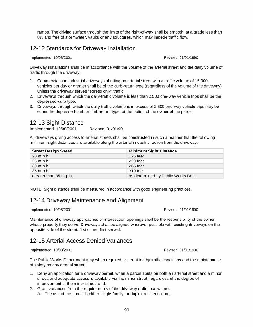
90
ramps. The driving surface through the limits of the right-of-way shall be smooth, at a grade less than
8% and free of stormwater, vaults or any structures, which may impede traffic flow.
12-12 Standards for Driveway Installation
Implemented: 10/08/2001 Revised: 01/01/1990
Driveway installations shall be in accordance with the volume of the arterial street and the daily volume of
traffic through the driveway.
1. Commercial and industrial driveways abutting an arterial street with a traffic volume of 15,000
vehicles per day or greater shall be of the curb-return type (regardless of the volume of the driveway)
unless the driveway serves "egress only" traffic.
2. Driveways through which the daily-traffic volume is less than 2,500 one-way vehicle trips shall be the
depressed-curb type.
3. Driveways through which the daily-traffic volume is in excess of 2,500 one-way vehicle trips may be
either the depressed-curb or curb-return type, at the option of the owner of the parcel.
12-13 Sight Distance Implemented: 10/08/2001 Revised: 01/01/90
All driveways giving access to arterial streets shall be constructed in such a manner that the following
minimum sight distances are available along the arterial in each direction from the driveway:
Street Design Speed Minimum Sight Distance
20 m.p.h. 175 feet
25 m.p.h. 220 feet
30 m.p.h. 265 feet
35 m.p.h. 310 feet
greater than 35 m.p.h. as determined by Public Works Dept.
NOTE: Sight distance shall be measured in accordance with good engineering practices.
12-14 Driveway Maintenance and Alignment
Implemented: 10/08/2001 Revised: 01/01/1990
Maintenance of driveway approaches or intersection openings shall be the responsibility of the owner
whose property they serve. Driveways shall be aligned wherever possible with existing driveways on the
opposite side of the street: first come, first served.
12-15 Arterial Access Denied Variances
Implemented: 10/08/2001 Revised: 01/01/1990
The Public Works Department may when required or permitted by traffic conditions and the maintenance
of safety on any arterial street:
1. Deny an application for a driveway permit, when a parcel abuts on both an arterial street and a minor
street, and adequate access is available via the minor street, regardless of the degree of
improvement of the minor street; and,
2. Grant variances from the requirements of the driveway ordinance where:
A. The use of the parcel is either single-family, or duplex residential; or,
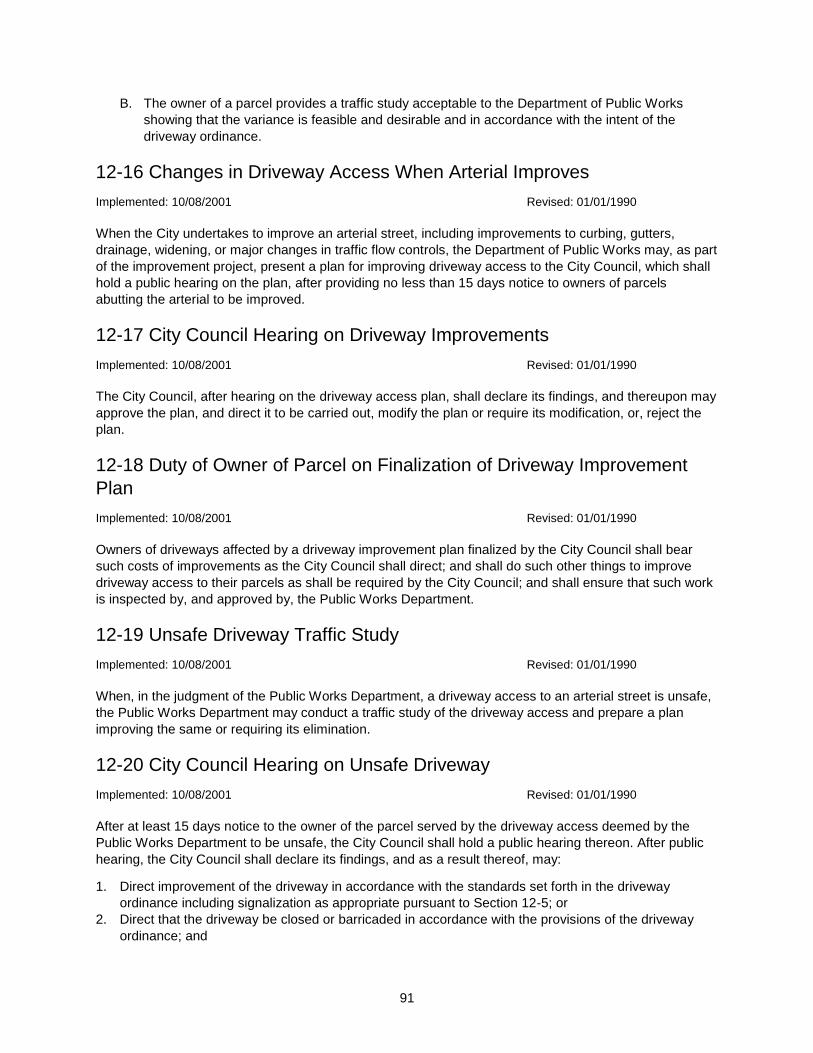
91
B. The owner of a parcel provides a traffic study acceptable to the Department of Public Works
showing that the variance is feasible and desirable and in accordance with the intent of the
driveway ordinance.
12-16 Changes in Driveway Access When Arterial Improves
Implemented: 10/08/2001 Revised: 01/01/1990
When the City undertakes to improve an arterial street, including improvements to curbing, gutters,
drainage, widening, or major changes in traffic flow controls, the Department of Public Works may, as part
of the improvement project, present a plan for improving driveway access to the City Council, which shall
hold a public hearing on the plan, after providing no less than 15 days notice to owners of parcels
abutting the arterial to be improved.
12-17 City Council Hearing on Driveway Improvements
Implemented: 10/08/2001 Revised: 01/01/1990
The City Council, after hearing on the driveway access plan, shall declare its findings, and thereupon may
approve the plan, and direct it to be carried out, modify the plan or require its modification, or, reject the
plan.
12-18 Duty of Owner of Parcel on Finalization of Driveway Improvement
Plan
Implemented: 10/08/2001 Revised: 01/01/1990
Owners of driveways affected by a driveway improvement plan finalized by the City Council shall bear
such costs of improvements as the City Council shall direct; and shall do such other things to improve
driveway access to their parcels as shall be required by the City Council; and shall ensure that such work
is inspected by, and approved by, the Public Works Department.
12-19 Unsafe Driveway Traffic Study
Implemented: 10/08/2001 Revised: 01/01/1990
When, in the judgment of the Public Works Department, a driveway access to an arterial street is unsafe,
the Public Works Department may conduct a traffic study of the driveway access and prepare a plan
improving the same or requiring its elimination.
12-20 City Council Hearing on Unsafe Driveway
Implemented: 10/08/2001 Revised: 01/01/1990
After at least 15 days notice to the owner of the parcel served by the driveway access deemed by the
Public Works Department to be unsafe, the City Council shall hold a public hearing thereon. After public
hearing, the City Council shall declare its findings, and as a result thereof, may:
1. Direct improvement of the driveway in accordance with the standards set forth in the driveway
ordinance including signalization as appropriate pursuant to Section 12-5; or
2. Direct that the driveway be closed or barricaded in accordance with the provisions of the driveway
ordinance; and
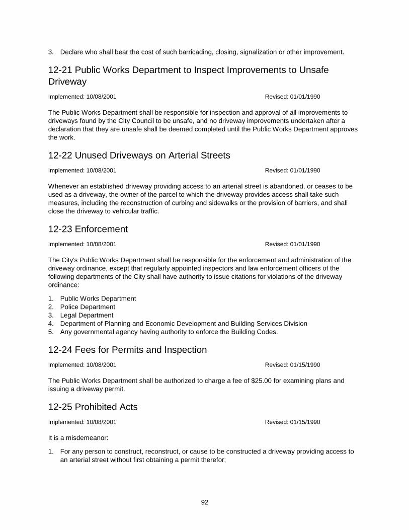
92
3. Declare who shall bear the cost of such barricading, closing, signalization or other improvement.
12-21 Public Works Department to Inspect Improvements to Unsafe
Driveway
Implemented: 10/08/2001 Revised: 01/01/1990
The Public Works Department shall be responsible for inspection and approval of all improvements to
driveways found by the City Council to be unsafe, and no driveway improvements undertaken after a
declaration that they are unsafe shall be deemed completed until the Public Works Department approves
the work.
12-22 Unused Driveways on Arterial Streets
Implemented: 10/08/2001 Revised: 01/01/1990
Whenever an established driveway providing access to an arterial street is abandoned, or ceases to be
used as a driveway, the owner of the parcel to which the driveway provides access shall take such
measures, including the reconstruction of curbing and sidewalks or the provision of barriers, and shall
close the driveway to vehicular traffic.
12-23 Enforcement
Implemented: 10/08/2001 Revised: 01/01/1990
The City's Public Works Department shall be responsible for the enforcement and administration of the
driveway ordinance, except that regularly appointed inspectors and law enforcement officers of the
following departments of the City shall have authority to issue citations for violations of the driveway
ordinance:
1. Public Works Department
2. Police Department
3. Legal Department
4. Department of Planning and Economic Development and Building Services Division
5. Any governmental agency having authority to enforce the Building Codes.
12-24 Fees for Permits and Inspection
Implemented: 10/08/2001 Revised: 01/15/1990
The Public Works Department shall be authorized to charge a fee of $25.00 for examining plans and
issuing a driveway permit.
12-25 Prohibited Acts
Implemented: 10/08/2001 Revised: 01/15/1990
It is a misdemeanor:
1. For any person to construct, reconstruct, or cause to be constructed a driveway providing access to
an arterial street without first obtaining a permit therefor;

93
2. For any person who is the owner of a parcel abutting on an arterial street, to occupy the parcel while
it is served by a driveway that was constructed or reconstructed after the effective date of the
ordinance without first obtaining a permit required by the driveway ordinance;
3. For any person who is the owner of a parcel abutting on an arterial street to allow the existence of an
abandoned or unused driveway that provides access to the arterial street; or,
4. To fail to comply with the directions of the City Council relating to the improvement, barricading, or
closing of any driveway.
12-26 Nuisances Declared - Abatement
Implemented: 10/08/2001 Revised: 01/15/1990
The City may undertake an action to abate nuisance driveways in accordance with the procedures for
abatement of nuisances provided by the City's criminal code or otherwise by law. Nuisance driveways
are those driveways providing access from a parcel to an arterial street that have been constructed or
reconstructed after the effective date of the driveway ordinance without first having obtained a permit, or
that have been abandoned or have fallen into disuse but are still passable to vehicular traffic, or that have
been allowed by the parcel's owner to continue to exist unchanged for more than 120 days after the City
Council has directed that the driveway be improved, closed, or barricaded.
12-27 Safe Access to Public Streets
Implemented: 10/08/2001 Revised: 01/15/1990
Access to public streets and alleys shall be located to minimize safety hazards. The Public Works Director
may deny access to a street or alley where physical conditions create a safety hazard. The criteria for
evaluating locations shall be based on the Manual on Uniform Traffic Control Devices, Washington State
Department of Transportation Standards, Institute of Traffic Engineers Standards, and AASHTO
Standards.
94
Section 13. Subdivisions
13-1 Introduction
Implemented: 10/08/2001 Revised: 01/01/1990
This section pertains to the subdivision of land within the corporate limits of the City of Bellingham, which
is regulated by the Subdivision Ordinance (No. 8192). This section is intended to summarize the
ordinance, and if a conflict is perceived, the ordinance shall take precedence.
The Director of Planning and Economic Development is designated and assigned the administrative and
coordinating responsibility for approval or disapproval of plats and subdivisions within the City.
13-1.01 Compliance - Division into Nine or Fewer Lots (Ordinance 9390)
Implemented: 10/08/2001 Revised: 01/01/1990
Division of land into nine or fewer lots shall be in compliance with the regulations and standards of this
section governing "short subdivision" as set forth in Section 13-4. Division of land into ten or more lots
shall comply with regulations and standards dealing with subdivision and must follow the preliminary and
final platting procedures.
13-1.02 Sale Restrictions
Implemented: 10/08/2001 Revised: 01/01/1990
Sale of land is prohibited unless it is a duly platted parcel of land or lot, or is a tract of record at time of
passage of the ordinance (February 5, 1973) or is a parcel of land approved under short subdivisions,
Section 13-4.
13-1.03 Exceptions
Implemented: 10/08/2001 Revised: 01/01/1990
This section shall not apply to the following:
1. Cemeteries and other burial plots while used for that purpose.
2. Division of land into lots or tracts where the smallest lot is 20 acres or more and not
containing a dedication of a public right-of-way.
3. Divisions made by testamentary provisions or the laws of descent.
4. Divisions of land into lots or tracts classified for industrial or commercial use when the City of
Bellingham has approved a binding site plan for the use of the land pursuant to Section 13-7.
13-2 Definitions Implemented: 10/08/2001 Revised: 01/01/90
For the purpose of this section, unless it is clearly evident from the context that a different meaning is
intended, certain words and terms are defined as follows.
95
"Alley" means a public right-of-way, not greater than 30 feet in width, which affords a secondary access to
abutting property.
"Binding Site Plan" means a drawing to a scale which: (a) identifies and shows the areas and locations of
all streets, roads, improvements, utilities, open spaces, and any other matters specified by local
regulations; (b) contains inscriptions or attachments setting forth such appropriate limitations and
conditions for the use of the land as are established pursuant to Section 13-7.
"Block" means a group of lots, tracts, or parcels within well-defined and fixed boundaries.
"Building Setback Line" means a line parallel to the front property line in front of which no structure shall
be erected. The location of such line is determined from the regulations of Title 20.
"Cluster Subdivision" means a subdivision in which minimum lot size requirements may be diminished so
as to provide desirable open space with-out increasing the overall density of dwelling units per acre as
provided in Title 20.
"Commission" means the Bellingham City Land Use Commission.
"Controlling Corner" means all angle points of the perimeter of a subdivision or separate divisions of a
subdivision.
"Covenant" means a binding and solemn agreement made by two or more individuals, parties, etc., to do
or keep from doing a specified thing or things.
"Dedication" means the deliberate appropriation of land by an owner for any general and public uses
reserving to himself no other rights such as are compatible with the full exercise and enjoyment of the
public use to which the property has been devoted. The intention to dedicate shall be evidenced by the
owner by presenting the final plat or a short plat for filing by showing the dedication thereon; and the
acceptance by the public is evidenced by the approval of such plat for filing by the appropriate
governmental unit.
"Existing Street" means a presently traveled way with a minimum width of 18 feet of hard surfacing
irrespective of whether it has been accepted by the City for maintenance. A "hard-surfaced street" is a
street consisting of either portland cement or asphaltic concrete as a wearing surface.
"Greenbelt" means a parcel of land usually of strip or ribbon shape left in an undeveloped and natural
state, excluding all development except recreation.
"Lot Line Adjustment" means a division made for the purpose of adjusting boundary lines which does not
create any additional lot, tract, parcel, site or division nor create any lot, tract, parcel, site or division which
contains insufficient area and dimension to meet minimum requirements for width and area for a building
site.
"Through Lot" means a lot other than a corner lot abutting more than one street. "Pipe-Stem Lot"
(sometimes called a flag or panhandle lot) means a parcel of land which resembles a rectangle with a lot
taken out of a corner or corners leaving the remainder with considerably less width on the front lot line
than the width at the rear of the parcel.
"Metes and Bounds" means a description of real property which starts at a known point and describes the
bearings and distances of the line forming the boundaries of the property and is completed when the
description returns to the point of beginning.
"Monument" means an object used to permanently mark a surveyed location. The size, shape and design
of the monument is to be in accordance with standards specified by the Washington State Department of
Natural Resources as authorized by RCW 58.17.

96
"Neighborhood Standards" means the street standards specified in the applicable neighborhood of the
Comprehensive Plan of Bellingham.
"Open Space" means a parcel of land excluding building sites, parking areas, and access routes which is
designated and maintained as an area for leisure, recreation and other activities normally carried on
outdoors. Open space includes greenbelt and recreational areas.
"Plat" means a map or representation of a subdivision, showing thereon the division of a tract or parcel of
land into lots, blocks, streets and alleys or other division and dedications.
"Plat Certificate" means a title report by a title insurance company certifying the ownership, deed
restrictions, covenants, etc., of the land being subdivided.
"Final Plat" is the final drawing of the subdivision and dedication prepared for filing for record with the
County Auditor and containing all elements and requirements set forth in the ordinance.
"Preliminary Plat" is a neat and approximate drawing of a proposed subdivision showing the general
layout of streets and alleys, lots, blocks, and restrictive covenants applicable to the subdivision, and other
elements of a plat or subdivision which furnish a basis for the approval or disapproval of the general
layout of a subdivision.
"Short Plat" is the map of representation of a short subdivision.
"Accepted Street" means a street that has been accepted for maintenance. Usually any street that has or
had been improved to the prevailing minimum City standard is regarded as an accepted street. The City
has pledged that the accepted streets will be kept in repair and maintained at no expense to the abutting
property owners.
"Arterial Street" means an existing or proposed roadway designated an arterial by City ordinances, or a
roadway carrying more than 1,500 vehicles per day.
"Collector Street" means a roadway designed to carry medium volumes of vehicular traffic, provide
access to the major street system, and collect the vehicular traffic from the intersecting minor streets.
"Cul-de-sac" means a street intersecting another street at one end and permanently terminated by a
vehicular turnaround at the other end.
"Local or Minor-Access Street" means a street providing vehicular access to abutting properties.
"Marginal-Access Street" means a street parallel to and adjacent to a major arterial which provides
access to the properties abutting it and which separates the abutting properties from high-speed vehicular
traffic.
"Subdivision" means a division or resubdivision of land into 5 or more lots, tracts, parcels, sites or
divisions.
"Short Subdivision" means a division or redivision of land into 9 or fewer lots, tracts, parcels, sites or
subdivisions for the purpose of sale, lease or transfer of ownership.
13-3 Lot Line Adjustments
Implemented: 10/08/2001 Revised: 01/01/1990
Ordinance 9135
97
13-3.01 Approval Required
Implemented: 10/08/2001 Revised: 01/01/1990
Any action which will result in a lot line adjustment as defined in this section shall be submitted to the
Planning and Economic Development Department for approval prior to recording.
13-3.02 Procedure
Implemented: 10/08/2001 Revised: 01/01/1990
The proposal shall be submitted to the Department of Planning and Economic Development for review on
forms provided by that department. A pencil drawing showing the existing and proposed lot line shall
accompany the application together with a $25.00 review fee. A filing fee of $25.00 per lot shall be
collected prior to recording with the County Auditor. (Ordinance 9630)
The Department of Planning and Economic Development shall give preliminary approval to the request if
it finds that:
1. No new lots are created;
2. Each parcel as proposed meets minimum lot standards as specified in Section 13-10, or that each
parcel, if already less than the required minimum, is not further reduced as a result of the proposed
lot line adjustment;
3. The lot line adjustment does not further infringe on any applicable section of the City Land Use
Development Ordinance.
Upon receiving preliminary approval, the applicant(s) shall have prepared a mylar as described in
Section 13-3.03 to be recorded in the County Auditor's office at the expense of the applicant after
receiving final City approval.
13-3.03 Mylar
Implemented: 10/08/2001 Revised: 01/01/1990
A document of mylar quality or better shall be prepared by a State of Washington licensed land surveyor
based upon a record survey. The mylar shall be 18 inches by 18 inches in size and shall clearly indicate
the previous and new lot lines and shall be signed by all property owners in whom title is vested and shall
be notarized. A space shall be reserved for legal descriptions, and authorized signatures of the land
surveyor, Planning and Economic Development Department and Auditor's office. A reproducible copy of
the recorded mylar shall be submitted to the City for their records on the day of recording. (Ordinance
9550)
13-4 Short Subdivisions
Implemented: 10/08/2001 Revised: 01/01/1990
Any action which will result in a short subdivision of any lot, tract, parcel, or plot of land for any reason
whatsoever shall be subject to approval by the Department of Planning and Economic Development.
Approval shall be based on standards and conditions set forth in this section.
13-4.01 Approval Procedure
Implemented: 10/08/2001 Revised: 01/01/1990
98
1. All short subdivisions shall be submitted to the Department of Planning and Economic Development
for review and approval. Approving, with specified alterations, or disapproving action will be taken by
the Director of Planning and Economic Development within 30 days of the submission date unless the
applicant consents to a time extension.
2. An application for approval of a short subdivision shall be accompanied by an accurately-scaled and -
dimensioned drawing of the proposed subdivision prepared by a registered land surveyor. Such
drawing shall be on 11-inch by 17-inch paper. Four copies shall be submitted if the property is
residential, 5 copies if it is commercial or industrial. (Ordinance 9550)
3. An environmental checklist shall be completed and submitted with any application for short
subdivision of property within shoreline jurisdiction. (Ordinance 9550)
4. The application shall contain an accurate legal description of the area involved in the subdivision. In
the event the boundaries are described by metes and bounds, the accuracy of the description shall
be attested to and signed by a registered land surveyor. Basis of bearings shall be stated.
5. The total property owned by the applicant which is contiguous to the parcel being subdivided shall be
accurately indicated on the drawing. All existing buildings on the property being subdivided must be
accurately illustrated on the drawing. In addition, all adjacent property and owners must be clearly
shown on the drawing.
6. In the event the proposed subdivision is not sewered, a recommendation for approval from the Health
Department shall be obtained prior to approval by the Planning and Economic Development Director.
7. In the event the proposed subdivision results in lots smaller than required in Title 20, the Planning
and Economic Development Director has the authority to approve the short subdivision if the resulting
new lots are larger than those previously existing.
8. All short subdivisions shall comply with the provisions of the ordinances of the City relating to
drainage, and development of land within the flood plains of the City. (Ordinance 8827)
9. In the event the land to be subdivided has a slope or slopes of more than 20% and/or has rock or
unstable soil conditions, the subdivider shall furnish soils data to the City Engineer. If conditions
warrant control measures to correct slide, erosion or other similar problems, the subdivider shall be
responsible for the design, installation and expense of any device or corrective measure, subject to
approval of the City Engineer.
10. After preliminary approval is received from the City, the applicant shall provide a document of mylar
quality or better which has been prepared by a State of Washington licensed land surveyor based
upon a record of survey. Said mylar shall be 18 inches square, clearly indicate the new lot lines, be
signed by all property owners in whom title is vested and shall be notarized. A space shall be
reserved for legal descriptions, and authorized signatures of the land surveyor, Public Works
Department, Planning and Economic Development Department, Whatcom County Health
Department, if necessary, and Auditor's office. A reproducible copy of the recorded mylar shall be
submitted to the City for their records on the day of recording. (Ordinance 9390 and 9550)
11. A plat certificate shall be required to be submitted with the checkprints of the mylar. (Ordinance 9550)
12. Permanent control monuments shall be established at each and every controlling corner on the
boundaries of the parcel of land being subdivided, and in the centers of all intersecting streets.
Additional monuments shall be installed if requested. (Ordinance 9390)
13. For short subdivisions consisting of 5 or more lots, the application shall be accompanied by a
notarized list of all property owners and their mailing address who own land within 300 feet of the
boundaries of the property being proposed to be subdivided. The list of all such property owners shall
be obtained from the latest available records of the Whatcom County Assessor's Office. No
responsibility will be assumed by the applicant in the event the County Assessor's records contain
inaccurate or incomplete information. (Ordinance 9390)
The Planning and Economic Development Department shall send notice to all persons on the list
informing them of the proposed short subdivision and invite comments to be made in writing within 20
calendar days of said notice. (Ordinance 9390)
14. For short subdivision and preliminary plats adjacent to the right-of-way of a State highway or within 2
miles of the boundary of a state or municipal airport, written notice including a legal description of the
99
short subdivision and a location map shall be sent to the Secretary of Transportation. The Secretary
shall respond within 15 days of said notice as to the effect that the proposed subdivision will have on
the state highway or the state or municipal airport. Notice of intent to short subdivide shall also be
sent to the local airport authority.
13-4.02 Lot Requirements - Design Standards
Implemented: 10/08/2001 Revised: 01/01/1990
All lots created by a short subdivision shall abut upon a dedicated or deeded street and such street to
have no less than 60 feet of right-of-way width if a through street, or 50 feet of width if a cul-de-sac; in the
event the abutting street does not meet these minimum width standards, additional right-of-way shall be
required prior to approval of a short subdivision provided that this requirement may be waived if, in the
opinion of the Planning and Economic Development Director and City Engineer, such additional
right-of-way will not be necessary for the future traffic circulation of the City.
Short subdivisions that contain a dedication of land to the public shall be surveyed, monumented and
recorded with the County Auditor. The monumentation requirement may be waived, if the centerline of the
right-of-way is already monumented.
All lots created by a short subdivision shall meet the design standards specified in Section 13-10;
however, the Planning and Economic Development Director may approve a division of land less than the
required standards, provided such division of property results in better lot design than previously existed.
Better lot design is defined as meaning such items as larger in area, more practical site because of
topography or nearer to conformance to required standards.
For short subdivisions consisting of 5 or more lots, the cluster provision of Section 13-9 shall not be
utilized. (Ordinance 9390)
13-4.03 Required Improvements
Implemented: 10/08/2001 Revised: 01/01/1990
1. Prior to granting approval for any short subdivision, the Planning and Economic Development Director
shall ascertain the following improvements have been made or installed for each parcel created by
the division of land:
A. City water.
B. Sanitary sewer or Health Department approval of septic tanks.
C. Appropriate dedications or easements made, if required.
2. All improvements shall be constructed in accordance with a contract between the subdivider and the
City, providing at least:
A. Terms and conditions satisfactory to the City, including design and construction standards;
B. Requiring a permit to be issued before commencement of construction; and
C. In the discretion of the Director of Public Works, appropriate security may be required, covering
construction performance and guaranteeing the construction after completion for a period of one
year.
3. Streets, Curbs, Gutter, Sidewalks (Ordinance 9390)
A. For short subdivisions consisting of 4 or fewer lots:
i. When the principal frontage street providing access to a newly-created lot is below the
standard for an existing street, the installation of a street is required prior to approval of a
short subdivision. The newly-installed street shall have a minimum traveled way brought to
line and grade of not less than 20 feet of width with 4-foot shoulders on each side. The
100
surface shall be at least of asphaltic concrete quality and there shall be adequate provision
for storm drainage.
ii. In the event the principal frontage street is not currently improved and is being created by full-
width dedication by the short division then a street constructed to full-neighborhood standards
shall be required.
B. For short subdivisions consisting of 5 to 9 lots:
i. All abutting street rights-of-way shall be constructed to neighborhood standards or 3/4 full
City standards, whichever is the lesser standard.
ii. All interior streets shall be constructed to neighborhood standards.
iii. At least one street providing access to the short subdivision shall be improved to minimum
City standards.
iv. Appropriate security to ensure completion may be accepted in lieu of actual installation of the
required improvements, if acceptable to the Director of Public Works. (Ordinance 8827)
v. For all short subdivisions, when an extension to electric power and communication facilities is
necessary all such extensions shall be placed underground. (Ordinance 9390)
vi. For all short subdivisions, Staff shall have the authority to impose reasonable improvements
to control storm drainage runoff and to address any prerequisite consideration and special
conditions identified in the applicable section of the Comprehensive Plan. (Ordinance 9390)
13-4.04 Building Permit Issuance Restrictions
Implemented: 10/08/2001 Revised: 01/01/1990
No Building Permit shall be issued for construction of any kind unless:
1. Such lot was of record prior to August 17, 1964; or
2. Such lot is a division of a recorded subdivision; or
3. Such lot was created with approval of the City in accordance with Ordinance 7483 and/or 7995; or
4. Such lot was created in compliance with the provisions of this section.
It shall be the responsibility of the property owner to establish the status of the lot as it pertains to this
section.
13-4.05 Resubdivision Restricted
Implemented: 10/08/2001 Revised: 01/01/1990
Any short subdivision or land involved in a short subdivision shall not be resubdivided for a period of 5
years from the date of approval of the short subdivision without the submission and approval of a final plat
done in accordance with Section 13-6.
13-4.06 Inspection Fee
Implemented: 10/08/2001 Revised: 01/01/1990
(Ordinance 8724, amended by Ordinance 9630)
Any person making application for a short subdivision permit, shall at the time of application pay a base
fee of $100.00. The filing fee of $25.00 per lot shall be collected prior to recording with the County
Auditor. Such fees shall be nonrefundable, unless such obligation is specifically waived by the City
Council.

101
13-5 Preliminary Plats
Implemented: 10/08/2001 Revised: 01/01/1990
Any property owner who wishes to divide land into 10 or more lots shall conform to the regulations
hereafter stated as they pertain to preliminary plats, subdivision design, improvements and final plats.
These regulations also pertain to land that has had an approved short subdivision during the previous 5
years and also to lots being replatted due to street vacations.
13-5.01 Contents
Implemented: 10/08/2001 Revised: 01/01/1990
A preliminary plat submitted for approval shall contain the following items and information:
1. Name of plat;
2. Name, address and phone number of subdivider (owner) and the land surveyor;
3. All lots, rights-of-way, open space, existing easements, and other features affecting the design of the
plat;
4. Topography lines at 5-foot intervals;
5. All parcels of land intended to be dedicated or temporarily reserved for public use and the conditions
attached thereto accurately indicated.
6. A vicinity sketch at a scale of not more than 800 feet to the inch showing the proposed plat in relation
to surrounding land; all platted rights-of-way for a distance of at least a quarter of a mile, and
additional area, if necessary, to show connecting streets or arterials.
7. An accurate and complete legal description of the area being platted;
8. Source of water supply, method of sewage disposal and method of surface water disposal;
9. The land use classification, both present and proposed;
10. All existing conditions shall be delineated. The location, width and names of all existing or prior
platted streets or other public ways, railroad and utility rights-of-way, parks and other public open
spaces, permanent buildings and structures, and section and municipal corporation lines within or
adjacent to the tract shall be shown. In the case of a replat, the lots, blocks, streets, alleys,
easements, and parks, of the original plat being vacated, shall be shown by dotted lines in their
proper position in relation to the new arrangement of the plat; the new plat being clearly shown in
solid lines so as to avoid ambiguity. Existing sewers and water lines, culverts or other underground
facilities within the tract indicating pipe sizes, grades and exact location as obtained from public
records shall be shown. Boundary lines of adjacent tracts of unsubdivided and subdivided land
showing owners shall be indicated by dotted lines for a distance of three hundred feet. Existing
zoning of the proposed subdivision and adjacent tracts shall be shown.
11. An environmental checklist shall be required in accordance with RCW 43.21C upon the submittal of a
preliminary plat.
13-5.02 Preparation of Specifications
Implemented: 10/08/2001 Revised: 01/01/1990
The plat shall be prepared, drawn and certified by a land surveyor registered by the State of Washington.
The horizontal scale shall be no less than 100 feet to the inch. The plat shall conform with the design
standards governing plats as required by this ordinance. Sixteen copies of the plat shall accompany the
application for plat approval to permit distribution to the necessary persons, agencies, and organizations.
Any person making application for a preliminary plat approval shall at the time application is made pay a
base fee of $500.00, plus $25.00 for each lot proposed to be created. The fee shall be nonrefundable,
unless such obligation is specifically waived by the City Council. (Ordinance 8724)

102
13-5.03 Submission Time Limitation
Implemented: 10/08/2001 Revised: 01/01/1990
(Ordinance 8633)
Preliminary plats containing all of the information required by Sections 13-5.01 and 13-5.02 must be
submitted to the Planning and Economic Development Department no less than 4 weeks prior to the
Planning Commission meeting at which consideration is sought.
13-5.04 Public Hearing
Implemented: 10/08/2001 Revised: 01/01/1990
Upon receipt of a proposed preliminary plat, a public hearing before the Commission shall be scheduled.
Notice of such hearing shall be given by publication of at least one notice not less than 10 days prior to
the hearing in a newspaper in general circulation in the City. Three copies of the notice of hearing shall be
posted in at least 3 conspicuous places on the boundaries of the proposed plat at least one week prior to
the date of hearing. Individual notice shall be mailed to all property owners within 300 feet of any portion
of the proposed plat or any other land owned by the applicant that is adjacent to the proposed plat not
less than 10 days prior to the hearing. The actual cost of public notice, mailing and publication shall be
borne by the applicant.
13-5.05 Notification of Affected Agencies
Implemented: 10/08/2001 Revised: 01/01/1990
Upon receipt of a preliminary plat for approval, the following agencies and organizations shall be notified
of the date, place and hour of the public hearing and such notifications shall be accompanied by a copy of
the proposed plat:
1. Department of Public Works
2. Fire Department
3. The electrical distribution company
4. The telephone company
5. The gas company
6. County Council (if plat adjoins City limits)
7. The Washington State Department of Transportation (if plat adjoins State right-of-way)
8. The television cable company
13-5.06 Technical Review Committee
Implemented: 10/08/2001 Revised: 01/01/1990
Upon receipt of a preliminary plat, the Technical Review Committee consisting of the Planning and
Economic Development Director as Chairman, Public Works Director, Fire Chief, Traffic Superintendent,
or an authorized representative of each, shall, within 2 weeks of receipt of the preliminary plat, conduct an
informal meeting with the developer(s) for the purpose of reviewing and pointing out what, if any,
corrections, additions, deletions, etc., should be made to the preliminary plat prior to the Commission
public hearing. The recommendation of the Technical Review Committee shall be forwarded to the
Commission, City Council, and developer(s).
103
13-5.07 Commission Action
Implemented: 10/08/2001 Revised: 01/01/1990
The Commission shall hold a public hearing on each preliminary plat and shall review such plat to ensure
conformance with the policies as reflected by the Comprehensive Plan and with the planning standards
and specification of the City, including the Comprehensive Utility Plan. The Commission shall make a
recommendation to the City Council as to their findings with regard to determining if appropriate
provisions have been made for drainage, streets, alleys, other public ways, water, sewer, parks,
playgrounds, sites for schools, and any other relevant features necessary to serve the public interest.
Such recommendation shall be advisory only.
The recommendation of the Commission on a preliminary plat shall be submitted to the Council not later
than 14 days following the recommending action.
13-5.08 Council Review and Approval
Implemented: 10/08/2001 Revised: 01/01/1990
Upon the receipt of the preliminary plat, the Council shall at its next regular public meeting set the date for
a public meeting to be held to adopt or reject the recommendation of the Commission.
After considering the preliminary plat at the public meeting, the Council may adopt, change or reject the
recommendation of the Commission. If the Council adopts the recommendation of the Commission, no
further action is required of the Council or Commission relative to the Preliminary Plat. However, if the
Council deems it necessary to change or reject the Commission's recommendation, a duly-advertised
public hearing shall be held to consider the matter and thereafter the Council may adopt its own
recommendations and approve or disapprove the preliminary plat.
Acting on the recommendations of the Commission, the Council shall determine if appropriate provisions
have been made for drainage, streets, alleys and other public ways, water, sewer, parks, playgrounds,
sites for schools and any other relevant features necessary to serve the public interest. They shall
determine that the plat makes adequate provisions for the public health, safety and general welfare. After
making the above determinations the Council may then approve the plat.
13-5.09 Time Limits
Implemented: 10/08/2001 Revised: 01/01/1990
(Ordinance 8860, amended by Ordinance 9550)
Approval of a preliminary plat shall expire 3 years from the date of Council approval. Upon application by
the subdivider, the Commission with approval of the City Council, shall have the authority to grant an
extension for one additional year. The applicant must file a written request with the Planning Commission
at least 30 days before the expiration of the 3-year period. A one-year extension shall be granted upon a
showing that the applicant has attempted in good faith to submit the final plat within the 3-year period.
The subdivider may apply for subsequent one-year extensions. In approving subsequent one-year
extension requests, the City shall find that the proposed plat is still in conformance with the City's
Comprehensive Plan. The extension shall be conditional upon the plat meeting all subdivision
requirements which are in effect at the time the extension is granted.
In the event a portion of an approved preliminary plat is developed and recorded as a final plat and the
remainder of the overall plat is left undeveloped for a period of 3 years from the date of the recording of

104
the divisions, then the approval of the preliminary plat shall expire. The time limit may be extended as
provided for in this section.
13-5.10 Modification of Standards
Implemented: 10/08/2001 Revised: 01/01/1990
(Ordinance 8492)
Circumstances may exist so as to justify modification of established subdivision development standards.
(See Ordinance 8192, Section 18.16 for requirements, procedure, and limitations.)
13-6 Final Plat
Implemented: 10/08/2001 Revised: 01/01/1990
13-6.01 Conformance with Ordinance Required
Implemented: 10/08/2001 Revised: 01/01/1990
Prior to submission of a final plat for approval, the plat shall conform in all respects to the design
standards and improvements requirements specified in the ordinance. Submission of the final plat,
together with all required data shall be submitted to the Planning and Economic Development Director at
least one month prior to the date of consideration by the City Council.
13-6.02 Conformance With Preliminary Plat
Implemented: 10/08/2001 Revised: 01/01/1990
The final plat shall conform to the preliminary plat design; however, slight deviations may be allowed by
the Technical Review Committee if they determine such deviations are necessary because of unforeseen
technical problems and that the change will result in a better plat.
13-6.03 Legal Description
Implemented: 10/08/2001 Revised: 01/01/1990
A complete legal description shall be shown in its entirety on the face of the plat. The plat shall be
accompanied by a complete survey of the section or sections in which the plat or replat is located, or as
much thereof as may be necessary to properly orient the plat within such section or sections, and
showing relationship to abutting plats and properties. The plat and section survey shall be submitted with
descriptions of the same and the actual traverse showing errors of closure and method of balancing. A
work sheet showing all distances, bearings, and other related calculations required to determine corners
and distances of the plat shall accompany this data. The allowable plat map error of closure shall not
exceed one foot in 10,000 feet. Basis of bearing shall be shown based upon a line between two found
monuments, and they shall be shown on the plat, together with description of found monuments and
bearing distance between them. Bearings shall be listed to nearest second (01") and distances to be
listed to nearest hundredth of a foot.
For every existing monument used in control for plat boundary, and new plat monuments on existing
street rights-of-way, there shall be a minimum of 3 direct measurement distances to substantial reference
points (nail and shiner, iron pipe, etc.) These measurements may be submitted on 3 by 5 inch tie cards
furnished by the City.
105
13-6.04 Covenants
Implemented: 10/08/2001 Revised: 01/01/1990
A copy of any covenants which are drafted in conjunction with, or as a result of a plat, shall accompany
the final plat and shall become a part of it. Said covenants shall be recorded with the final plat
13-6.05 Plat Certificate
Implemented: 10/08/2001 Revised: 01/01/1990
A current plat certificate by a recognized title company shall accompany the final plat upon submission to
the City Council for approval. Current shall be construed as no older than 7 days.
13-6.06 Dedication of Public Lands
Implemented: 10/08/2001 Revised: 01/01/1990
The face of the plat shall contain a dedication of all lands to be conveyed to the public, which shall be
signed by the legal property owners. The signatures of the owners shall be acknowledged by a notary
public.
13-6.07 Land Surveyor Seal
Implemented: 10/08/2001 Revised: 01/01/1990
The survey of the proposed subdivision and preparation of the plat shall be made by or under the
supervision of a registered land surveyor who shall certify on the plat that it is a true and correct
representation of the lands actually surveyed.
13-6.08 Health Department Approval
Implemented: 10/08/2001 Revised: 01/01/1990
The plat shall be accompanied by a recommendation from the local Health Department and/or the City
Public Works Department as to the adequacy of the proposed means of sewage disposal and water
supply.
13-6.09 City Engineer Approval
Implemented: 10/08/2001 Revised: 01/01/1990
Each final plat shall be checked and approved by the City Engineer. If the final plat contains more than
one sheet, there shall be a City Engineer's certificate on each sheet.
13-6.10 Inspection Fee
Implemented: 10/08/2001 Revised: 01/01/1990
(Ordinance 8724)
A basic fee of $50.00, plus $110.00 per lot, is hereby imposed to defray the City's costs of field checking,
plan review, and public service inspection of sewer mains, water mains, street installation, and other
required public work improvements.

106
13-6.11 Finance Director Approval
Implemented: 10/08/2001 Revised: 01/01/1990
Each plat shall contain the certification of the City Finance Director that all filing fees, City taxes, and
assessments and other fees for which the property may be liable have been paid. Also, in order to keep
the capital improvements costs of the City's utility systems current, the following estimated or actual costs
will be submitted to the City's Accounting Division before the City Treasurer shall approve the final plat:
1. Water Mains - total costs, labor, equipment, materials with size and number of feet.
2. Hydrants - give number put in, size and cost.
3. Storm Sewer - total cost with size and number of feet.
4. Sanitary Sewer - total cost with size and number of feet.
5. Streets - total cost and number of feet put in.
6. Sidewalks and Curbs - total cost.
13-6.12 Director of Planning and Economic Development Action
Implemented: 10/08/2001 Revised: 01/01/1990
The Planning and Economic Development Director shall review the final plat for conformance with the
approved preliminary plat, for completion of all the requirements contained in the subdivision ordinance,
and for conformance with other standards or codes which pertain to the plat. Upon determination that
platting requirements have been satisfied, the Planning and Economic Development Director shall
approve the plat by signature and forward the plat to the City Council for action.
13-6.13 Council Review and Approval
Implemented: 10/08/2001 Revised: 01/01/1990
The City Council shall review the final plat and if the Council finds that the public use and interest will be
served by the proposed plat, and that said plat meets the requirements of the subdivision ordinance and
any other state or local ordinances pertaining thereto, it shall suitably inscribe and execute its approval on
the face of the plat.
13-6.14 Filing With County Auditor
Implemented: 10/08/2001 Revised: 01/01/1990
The final approved plat shall be filed for record with the County Auditor in compliance with state and
county laws and regulations.
13-6.15 Copy Furnished by Subdivider
Implemented: 10/08/2001 Revised: 01/01/1990
In accordance with the state law and with regulations of the subdivision ordinance the subdivider shall,
without cost to the City, furnish copy, mylar or better quality, of the final plat as filed.
13-7 Site Plan for Land Divisions for Lease
Implemented: 10/08/2001 Revised: 01/01/1990
Binding Site Plan, Ordinance 8512
107
13-7.01 Applicability
Implemented: 10/08/2001 Revised: 01/01/1990
This section applies to divisions of land for the purpose of lease when no trailers or accessory, security,
or managerial quarters are permitted to be placed upon the land.
13-7.02 Submission Requirements
Implemented: 10/08/2001 Revised: 01/01/1990
1. The following information shall be used in mandatory preliminary design discussions with the
Department of Planning and Economic Development. Such information shall be prepared by the
applicant.
A. Map of the topography of the site at 5-foot contour intervals (based on City datum) and
identification of the existing drainage pattern.
B. All existing rights-of-way, easements, utilities, and other existing public improvements.
C. All parcels of land intended to be dedicated or reserved for public use, proposed public and/or
private streets and open spaces.
2. Submission requirements listed in Subsections 1 A-C of this section shall be included on a single map
which shall be prepared by a registered architect, civil engineer, or land surveyor.
3. The horizontal scale ratio of the preliminary site plan shall be no more than 1:2400 (1" = 200'). The
map shall include the property included in the proposed plan and adjacent lands for a distance of 300
feet.
13-7.03 Preliminary Plan Approval
Implemented: 10/08/2001 Revised: 01/01/1990
The applicant shall submit 10 copies of the preliminary plan which clearly shows all items set forth in
Section 13-7.02. In addition, the following information shall be submitted:
1. An accurate and complete legal description with area in acres together with a plat certificate dated
within 7 days of the preliminary plat submittal. Copies of all deeds and easements referred to in the
plat certificate shall be furnished with the submittal.
2. The name, addresses, and telephones number of the owner and the professional preparing the plan.
3. Calculations of cumulative pre-development and post-development storm water runoff volumes and
proposed methods of controlling post-development runoff rates.
4. At least one map at a scale of 1" = 200' depicting items listed above.
5. A completed environmental checklist as supplied by the Department of Planning and Economic
Development.
Following receipt of a properly-prepared preliminary plan, the Planning and Economic Development
Department shall schedule a meeting of the Technical Review Committee. Such meeting shall be
scheduled no less than 10 days nor more than 30 days from the date of receipt of said preliminary plan.
The applicant and the professional preparing the plan shall be notified of the date, time, and location of
said meeting.
All conditions, requirements, or alterations in the proposed site plan resulting from review of the Technical
Review Committee shall be transmitted, in writing to the applicant and/or their representative.
13-7.04 Required Improvements
Implemented: 10/08/2001 Revised: 01/01/1990
108
Prior to granting approval for any binding site plan, the Department of Public Works shall ascertain that
City water and sanitary sewer improvements, plus appropriate dedications or easements, have been
provided or will be provided. Performance bonds may be accepted in lieu of installation of the required
improvements subject to approval of the Department of Public Works. If the development of the site is to
be done in phases, the applicant shall submit a schedule of installation of required improvements to
coincide with development phasing. Such improvement schedule is subject to approval of the Director of
Public Works.
13-7.05 Street Installations
Implemented: 10/08/2001 Revised: 01/01/1990
In the event the principal frontage street providing access to the binding site plan is below the standard
for an existing street, the installation of a street may be required prior to approval. If required, the street
shall have a minimum traveled way brought to line and grade of not less than 20 feet of width with 4-foot
shoulders on each side. The surface shall be at least of asphalt concrete quality and there shall be
adequate provision for storm drainage. In addition, the applicant shall be required to sign a commitment
to support a local improvement district (LID) for the future installation of a full-standard street.
All streets providing access to the binding site plan shall have a right-of-way width of no less than 60 feet,
if a through street, or 50 feet if a cul-de-sac. In the event the abutting street does not meet these
minimum standards, additional right-of-way shall be required. This requirement may be waived if, in the
opinion of the Planning and Economic Development Director and the City Engineer, such additional right-
of-way is not necessary for the future traffic circulation of the City.
13-7.06 Contents and Specifications
Implemented: 10/08/2001 Revised: 01/01/1990
The applicant shall submit to the Planning and Economic Development Department the final binding site
plan, in reproducible form, depicting all improvements required by the Technical Review Committee. The
final plan shall conform to the following technical standards, and shall be prepared by a registered land
surveyor.
1. It shall be a plan legibly drawn, printed, or reproduced by a process guaranteeing a permanent record
on polyester-base film and shall include all required certificates.
2. The size of each sheet shall be 18 inches by 18 inches. A border line shall be drawn around each
sheet, with a blank margin of 1 inch on each edge. The scale of the plan shall be at least 1:1200 (1" =
100') but not larger than 1:240 (1" = 20') and shall show all details accurately and clearly.
Sufficient sheets shall be used to accomplish this. The particular number of the sheet and the total
number of sheets comprising the plan shall be stated on each of the sheets, and its relation to each
adjoining sheet shall be clearly shown.
3. The exterior boundary of the binding site plan shall be indicated by a heavy border.
4. The following shall be shown: North Arrows, plat drawing scale, i.e., 1:600 (1" = 50') (graphically and
feet per inch); included, if any with original block and lot numbers.
5. Each binding site plan shall have a distinct name, and a number assigned by the City.
6. Proper street names, and right-of-way widths and adjacent block lines shall be shown. If street
dedications, or additional right-of-way purchases have been made after the original plat filing date,
the Auditor's file number or deed number shall be shown in the area of the affected street right-of-
way. If the binding site plan includes a portion of a vacated street, the City vacation ordinance number
shall be shown within the vacated portion of the street.
7. A complete and accurate legal description of the total parcel included within the binding site plan shall
be shown. If a metes and bounds description is used, the basis of bearings shall be shown with
109
bearing and distance between them. The area of the total site and of each lot or parcel shall be
shown to nearest square foot on the plan.
8. All easements, whether public or exclusive, which affect the binding site plan shall be shown
graphically on the plan.
13-7.07 Attachment of Covenants, Limitations and Conditions
Implemented: 10/08/2001 Revised: 01/01/1990
A copy of any and all covenants, limitations and conditions which are drafted in conjunction with, or as a
result of a binding site plan, shall accompany the binding site plan and shall become part of it. Said
covenants, limitations and conditions shall either be shown on the face of the plan, or shall be recorded at
the County Auditor's office with the binding site plan.
13-7.08 Certifications and Dedications
Implemented: 10/08/2001 Revised: 01/01/1990
The following certifications shall appear on every binding site plan:
1. Land Surveyor Certification
2. Director of Public Works
3. Department of Planning and Economic Development
4. Covenants, Limitations and Conditions
5. County Auditor's Certificate
In accordance with state statutes, and regulations of this ordinance the land surveyor shall, at no cost to
the City, furnish the Department of Planning and Economic Development with one permanent mylar
original of the recorded binding site plan the same day as recording. The land surveyor shall also furnish
one reduced vellum or mylar copy of the binding site plan at a scale ratio of 1:2400 (1" = 200').
13-7.09 Restrictions Upon Issuance of Building Permits
Implemented: 10/08/2001 Revised: 01/01/1990
No building permit shall be issued for construction of any kind upon the property in question unless such
parcel, tract, or lot was created under the provisions of the chapter such building permit application is
accompanied by a detailed plot plan clearly showing relationship of proposed structure, parking facilities,
landscaping and drainage to the parcel lease boundary.
It is the responsibility of the building permit applicant to furnish the required information, and to establish
the status of the parcel, tract or lot as it pertains to this chapter.
13-8 General Improvement Standards
Implemented: 10/08/2001 Revised: 01/01/1990
13-8.01 Drawings Required
Implemented: 10/08/2001 Revised: 01/01/1990
The developer shall submit to the City Engineer profiles of the proposed streets, drainage plans, and
right-of-way section drawings, including utility line placement, for approval before any ground work is
begun. All design drawings shall be prepared by a State of Washington registered professional engineer.
110
Because "as built" underground utility locations sometimes differ significantly from original designs, the
developer shall submit to the City Engineer "as built" drawings of all underground utility placements upon
completed installations of said utilities.
13-8.02 Installations Prior to Final Plat Approval
Implemented: 10/08/2001 Revised: 01/01/1990
Prior to the submission of a final plat for approval, all streets, alleys, sidewalks, storm drainage, utilities,
monumentation, streetlights, street trees, and any other improvements specified hereunder shall be
installed and completed by the subdivider to the satisfaction of the Public Works Director. Such
improvements shall meet the standards specified in the ordinance; provided that a performance bond in
the amount of 150% of the value of the incomplete required improvements may be posted in lieu of
installation of improvements, and further provided that such bond is recommended by the Public Works
Director and approved by the City Council. The performance bond shall specify exactly what
improvements are covered and a time schedule for completion; however, at no time should the bond be
for more than a one-year period.
13-8.03 Contact Required for Dedicated Improvements
Implemented: 10/08/2001 Revised: 01/01/1990
(Ordinance 8792, amended)
All improvements constructed by a subdivider, which are to be dedicated to the City, shall be constructed
in accordance with a contract between the subdivider and the City. The contract shall provide terms and
conditions satisfactory to the City and a permit is required to be issued before commencement of
construction. At the discretion of the Director of Public Works, appropriate security may be required,
covering construction performance and guaranteeing the construction after completion for a period of one
year. The security requirement cannot be waived, however, if lots are to be sold before the construction is
completed.
13-8.04 Street and Roadway Standards
Implemented: 10/08/2001 Revised: 01/01/1990
All existing streets adjacent to a subdivision shall be brought to no less than the 3/4 standard specified in
Ordinance 8027 and 8040, as amended. All new streets and alleys within the subdivision shall be of the
width and quality to meet the full standards of the City.
13-8.05 Sidewalks
Implemented: 10/08/2001 Revised: 01/01/1990
Sidewalks shall be installed on both sides of each street. The minimum sidewalk width shall be 5 feet.
Sidewalks shall be required in dead end and cul-de-sac.
13-8.06 Pedestrian Ways
Implemented: 10/08/2001 Revised: 01/01/1990
Pedestrian ways may be required where blocks are exceptionally large or where there is a need for
pedestrian access in areas other than along streets. Such ways shall be at least 3 feet in width and shall
be surfaced with hard, dust-free, level material acceptable for walking.
111
13-8.07 Driveway Entrances
Implemented: 10/08/2001 Revised: 01/01/1990
The subdivider and/or developer shall predetermine the location of all driveway entrances prior to
approval of construction plans and driveway indentations shall be made at the same time the sidewalks
are constructed.
13-8.08 General Utility Installation
Implemented: 10/08/2001 Revised: 01/01/1990
All utilities (water, sewer, electrical, gas, and cable) shall be installed to the property line prior to
acceptance of public improvements.
13-8.09 Easements
Implemented: 10/08/2001 Revised: 01/01/1990
The subdivider shall reserve a strip of land 5 feet in width lying adjacent to each exterior side of all
dedicated public rights-of-way included in any plat. Said lands shall be recorded as public easements
and shall be used primarily for the installation of required service utilities. Any and all franchised utilities,
including City utilities, shall rightfully have access to and may use easements. Exclusive use rights cannot
be granted to any single or combination of utilities.
13-8.10 Water System
Implemented: 10/08/2001 Revised: 01/01/1990
A complete water distribution system shall be installed. Such system shall be adequate to serve the area
being platted. Each lot shall be connected to the water main by a service pipe extending at right angles
from the main to the property line and including a stopcock placed on the street side 5 feet out from the
property line. The connection to each lot shall be maintained by and kept within the exclusive control of
the City.
All water lines and services shall be placed prior to improvement of the streets and shall be constructed in
accordance with the appropriate codes and standards of the City of Bellingham. The developer shall pay
the flat-rate charge for water services at the time the completed services are installed.
13-8.11 Sanitary Sewer
Implemented: 10/08/2001 Revised: 06/01/1996
A sanitary sewer system shall be installed in such a manner where each and every building in which
people live, congregate, or are employed shall have a separate connection to the public sewer. Each
connection and each fixture emptying into and through the connection shall be installed in the manner
prescribed in the Plumbing Code of the City of Bellingham. All sewer mains in the subdivision shall be
constructed in conformance with all appropriate codes and standards.
13-8.12 Storm Drainage and Surface Water Runoff
Implemented: 10/08/2001 Revised: 06/01/1996
(Ordinance 10633)
112
Drainage facilities for controlling storm drainage and surface water runoff shall comply with the
ordinances of the City relating to drainage, including but not limited to, the submission and approval of
plans, and the construction of drainage facilities.
13-8.13 Electrical and Communication Facilities
Implemented: 10/08/2001 Revised: 06/01/1996
In all subdivisions, adequate and satisfactory installation of electric power and communication facilities
shall be required. All such facilities shall be installed underground except for the following:
1. Electric utility substations, pad-mounted transformers and switching facilities.
2. Electric transmission systems of a voltage of 55 KV or more.
3. TV cable amplifiers.
4. Telephone pedestals, cross-connect terminals, repeaters and cable warning signs.
5. Streetlighting standards.
6. Traffic-control equipment.
7. Temporary services for construction.
13-8.14 Streetlights and Name Signs
Implemented: 10/08/2001 Revised: 01/01/1990
The subdivider shall install at his expense streetlights and street name signs to the satisfaction of the
Technical Review Committee, and such facilities shall conform to the standards of the City of Bellingham.
13-8.15 Street Naming
Implemented: 10/08/2001 Revised: 01/01/1990
All street names shall be subject to approval of the Planning Commission. The Planning Commission
reserves the right to name or rename any street in any subdivision.
13-8.16 Flood Control
Implemented: 10/08/2001 Revised: 01/01/1990
Land which the Planning Commission has found to be unsuitable due to flooding, bad drainage or swamp
conditions likely to be harmful to the safety, welfare and general health of future residents, and the
Planning Commission considers inappropriate for development, shall not be subdivided unless adequate
means of control have been formulated by the subdivider and approved by the City Engineer.
13-8.17 Erosion and Slide-Corrective Measures
Implemented: 10/08/2001 Revised: 01/01/1990
In the event the land to be subdivided has a slope or slopes of more than 20% and/or has rock or
unstable soil conditions, the subdivider shall furnish soils data to the City Engineer. If conditions warrant
control measures to correct slide, erosion or other similar problems, the subdivider shall be responsible
for the design, installation and expense of any device or corrective measure subject to approval of the
City Engineer.

113
13-8.18 Monumentation
Implemented: 10/08/2001 Revised: 01/01/1990
Permanent-control monuments shall be established at each and every controlling corner on the
boundaries of the parcel of land being subdivided, and in the centers of all intersecting streets. Additional
monuments shall be installed if requested by the City Engineer.
13-8.19 Connection to Accepted Street
Implemented: 10/08/2001 Revised: 01/01/1990
All subdivisions shall be required to be connected to an accepted City street.
13-8.20 Street Trees
Implemented: 10/08/2001 Revised: 01/01/1990
Street trees shall be provided by the subdivider in all subdivisions within the dedicated public utility
easements adjacent to the street. There shall be a minimum of 2 trees per lot and street trees shall be
selected, installed and maintained in accordance with the standard engineering specifications.
13-8.21 Preservation of Existing Vegetation
Implemented: 10/08/2001 Revised: 01/01/1990
The subdivision shall be so designed as to preserve the greatest amount of existing on-site vegetation,
including trees with trunk diameter of 6 inches or greater, and other natural ground cover. Tree removal
shall be replaced where practical.
13-9 Cluster Subdivisions
Implemented: 10/08/2001 Revised: 01/01/1990
This section is applicable and can be utilized at the subdivider's option in residential-single areas which
have a "cluster," "cluster detached," or "cluster attached," use qualifier as part of the land use
classification of the City's Comprehensive Plan.
The purpose of this chapter is to allow variation in the required minimum lot size, provided the same
overall density is maintained, so as to preserve open space, tree cover, recreation areas or scenic vistas
or to reduce the amount of streets and utilities where appropriate.
13-9.01 Maximum Number of Lots
Implemented: 10/08/2001 Revised: 01/01/1990
The maximum number of lots which can be created utilizing this procedure can be determined by dividing
the total property size by the specified density found in the land use classification within the
Neighborhood Plan.
13-9.02 Reduction of Lot Size and Frontage
Implemented: 10/08/2001 Revised: 01/01/1990
114
Pursuant to this chapter, the minimum lot size and frontage requirements may be reduced provided that
at least 15% of the property's total property size is set aside for common open space.
13-9.03 Findings Prior to Approval
Implemented: 10/08/2001 Revised: 01/01/1990
Prior to cluster subdivision approval, the City must find that continued orderly development of adjacent
property will not be unduly jeopardized from the concentration of streets and utilities within the proposed
cluster subdivision, or cannot be reasonably serviced from the proposed cluster subdivision due to
extreme environmental conditions.
13-9.04 Open Space
Implemented: 10/08/2001 Revised: 01/01/1990
The area designated as open space shall either be held in common among owners of the lots within the
subdivision or dedicated to the City if appropriate. However, if held in private ownership, all development
rights other than recreational in nature, shall be extinguished in the form of a recorded agreement. The
common private open space shall be clearly identified on the final plat. A homeowner's association
agreement shall be recorded after review by the Planning and Economic Development Department. Said
agreement shall clearly set out the rights, obligations and responsibilities of the owners of property
designated as common open space.
13-10 Lots and Blocks
Implemented: 10/08/2001 Revised: 01/01/1990
13-10.01 Through Lots
Implemented: 10/08/2001 Revised: 01/01/1990
Through lots shall not be allowed; however, if the subdivision abuts an arterial street, the lots on such
streets may be through lots provided the Planning Commission determines such a layout to be in the best
interests of safety and general welfare.
13-10.02 Lot Design
Implemented: 10/08/2001 Revised: 01/01/1990
All lots shall be of sufficient size to meet the site area requirements specified within the area's land use
designation under "density" found within the applicable Neighborhood Plan in which the property is
located; provided, however, that this minimum shall not be required in the following instances:
1. When there exists no specified minimum lot size in the subject area land use designation, in which
case the lot size shall be determined by the subdivider subject to any other applicable codes or
requirements;
2. Cluster lots which meet the requirements specified in Section 13-9;
3. Lot line adjustments pursuant to Section 13-3.01 for lots presently having less site area than the
required minimum lot size;
4. For existing lots of record under single ownership having a total site area in excess of the required
neighborhood density in which the case the number of possible lots shall be determined by dividing
the total amount of site area by the specified neighborhood density and rounding to the nearest whole
115
number. One-half shall be rounded to the higher whole number. All lots proposed under this
provision shall be as equal in site area as is practical.
Each lot shall have not less than 30 feet of frontage on a deeded or dedicated right-of-way. This width
shall be a consistent 30 feet or more from the right-of-way to the building setback line. The minimum lot
width at the building setback line shall be not less than 60 feet for interior lots and 70 feet for corner lots.
Lots utilizing less than a 40-foot frontage standard, with the exception of pipe-stem lots, shall have the
front yard setback line increased to 30 feet from the property line. (Ordinance 9550)
Pipe-stem lots shall only be permitted in a residential subdivision and short subdivision if the following are
met:
1. The minimum width of the minor or access portion of the lot shall be 30 feet; the lot width standard is
60 feet;
2. The access portion of the lot shall not be included in computations for meeting minimum density
requirements of the Neighborhood Plans;
3. A 5-foot setback from property lines for driveways in the access portion of the lot shall be recorded on
the face of the plat unless, in the judgment of the Planning and Economic Development Director, such
a requirement would be unfeasible due to topographical conditions;
4. No pipe-stem lot shall be permitted in short subdivisions where the ownership is common with
adjacent property;
5. Side-by-side pipe-stems in short subdivisions and subdivisions shall not be permitted unless, in the
judgment of the Planning and Economic Development Director in consultation with the City Engineer,
the design is necessary due to site conditions. Joint access may be required.
6. Joint access for pipe-stem and adjacent lots under common ownership at the time of division of
property shall be required. An access easement shall be recorded on the face of the plat. (Ordinance
9550)
Pipe-stem lots in commercial and industrial subdivisions shall be permitted only if the following are met:
1. The minimum width of the minor or access portion of the lot shall be 40 feet; the lot width standard is
60 feet. Minimum width of the minor or access portion may be decreased to 30 feet if joint access
with adjacent property is maintained and in the judgment of the City Engineer, no adverse traffic
impacts will result.
2. The access portion of the lot shall not abut property with a residential land use designation.
3. No pipe-stem lot shall be permitted in short subdivisions where the ownership is common with
adjacent property.
4. Side-by-side pipe-stems are permitted only if joint access is granted. Joint access for pipe-stem and
adjacent lots under common ownership at the time of division of property shall be required. An access
easement shall be recorded on the face of the plat. (Ordinance 9550)
13-10.03 Block Design
Implemented: 10/08/2001 Revised: 01/01/1990
The maximum length of a block is 1,320 feet. The maximum width is 500 feet. Where blocks exceed 500
feet in length, pedestrian easements may be required if deemed necessary.
13-11 Parks, Open Space, and Public Areas
Implemented: 10/08/2001 Revised: 01/01/1990

116
13-11.01 Provisions for Parklands
Implemented: 10/08/2001 Revised: 01/01/1990
In each subdivision, appropriate provisions shall be made for parks, playgrounds, open space and other
public areas. Provision of such areas may be made in one of the two following ways:
1. A minimum of 100 square feet of ground area per lot shall be provided in a location predetermined by
the City Park Plan.
2. In the event no proposed park or planned expansion of an existing park is located within the
boundaries of a subdivision, then the developer shall pay into a Special Park Site Acquisition Fund
the sum of $50.00 per lot. Such fund is to be used to acquire land for parks, playgrounds, open
space or greenbelts in areas deemed appropriate by the City Council.
13-11.02 Substitution of Greenbelts for Required Park Lands
Implemented: 10/08/2001 Revised: 01/01/1990
The developer may substitute open space or greenbelts for the above required park lands if, in the
opinion of the City Council, such areas are necessary for public welfare or safety. Open spaces or
greenbelts need not be dedicated to and maintained by the public and any substituted in lieu of park
lands shall be a continuing obligation of the owners of the subdivision.

117
Section 14. Figures
Figure 4-1 Horizontal Stopping Sight Distance
Implemented: 10/10/2001 Revised: 01/01/1990

118
Figure 4-2 Stopping Sight Distance for Crest Vertical Curves
Implemented: 10/10/2001 Revised: 01/01/1990
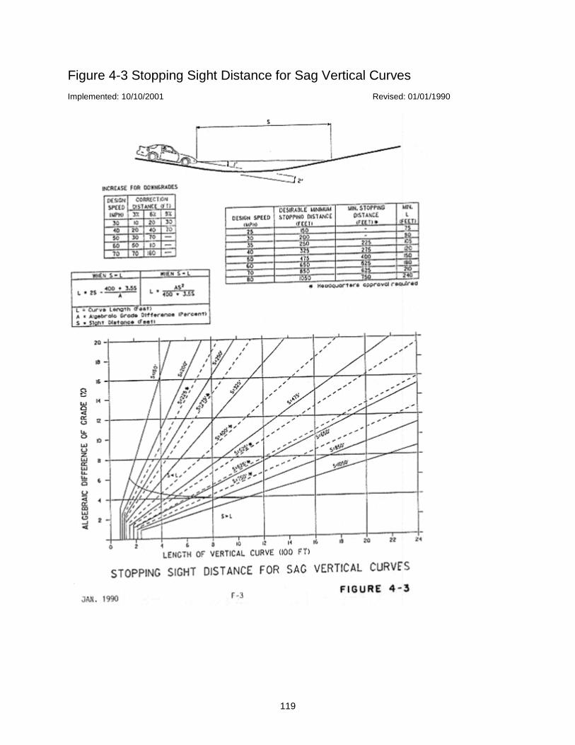
119
Figure 4-3 Stopping Sight Distance for Sag Vertical Curves
Implemented: 10/10/2001 Revised: 01/01/1990
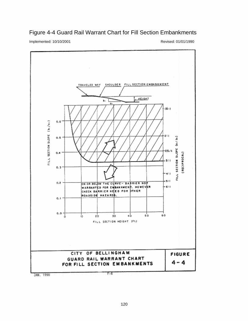
120
Figure 4-4 Guard Rail Warrant Chart for Fill Section Embankments
Implemented: 10/10/2001 Revised: 01/01/1990

121
Figure 4-5 Recovery Area
Implemented: 10/10/2001 Revised: 01/01/1990
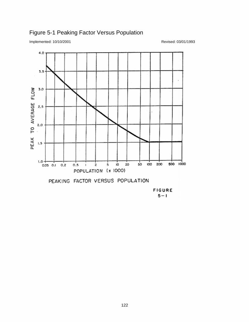
122
Figure 5-1 Peaking Factor Versus Population
Implemented: 10/10/2001 Revised: 03/01/1993

123
Figure 12-1 Driveway Width
Implemented: 10/10/2001 Revised: 03/01/1993

124
Figure 12-2 Distance from Intersections
Implemented: 10/10/2001 Revised: 03/01/1993
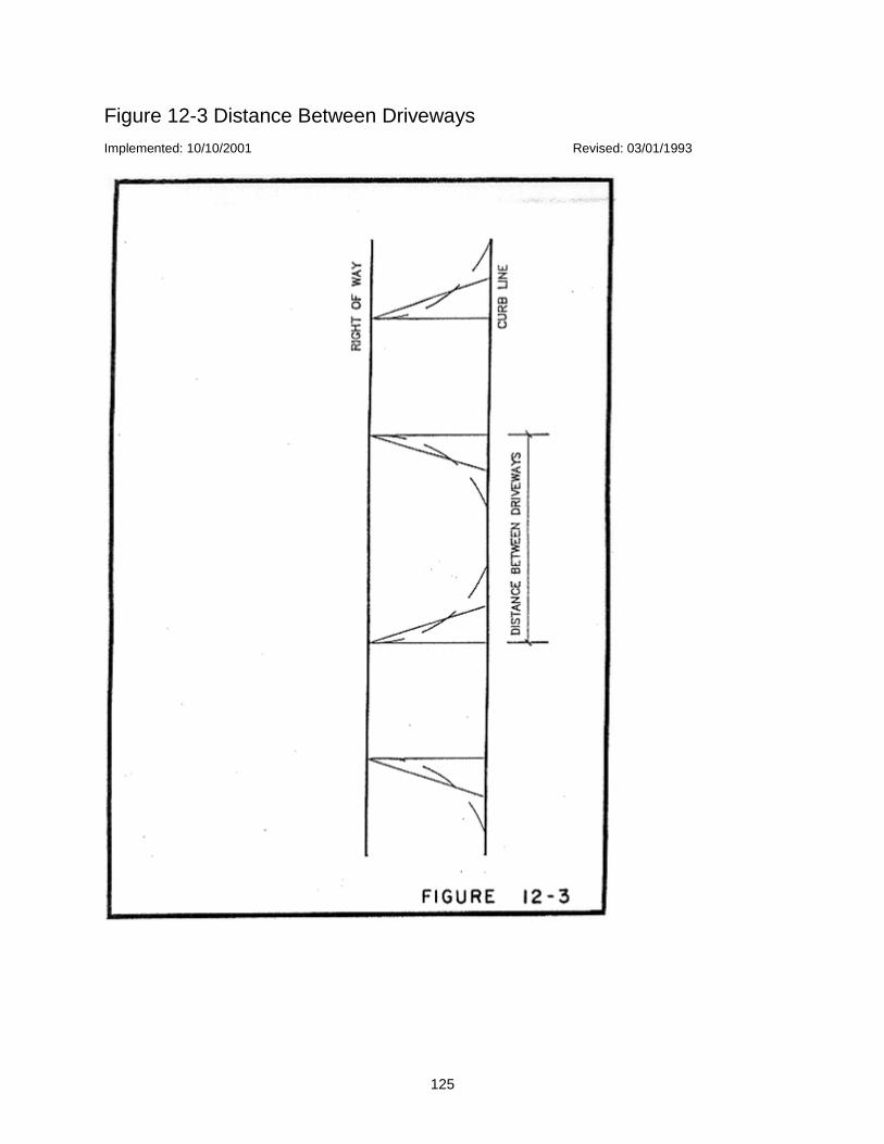
125
Figure 12-3 Distance Between Driveways
Implemented: 10/10/2001 Revised: 03/01/1993
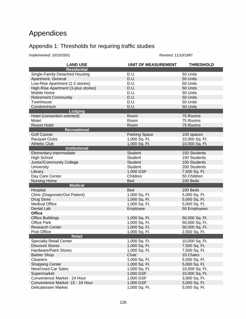
126
Appendices
Appendix 1: Thresholds for requiring traffic studies
Implemented: 10/10/2001 Revised: 11/10/1997
LAND USE UNIT OF MEASUREMENT THRESHOLD
Residential Single-Family Detached Housing D.U. 50 Units Apartment, General D.U. 50 Units Low-Rise Apartment (1-2 stories) D.U. 50 Units High-Rise Apartment (3-plus stories) D.U. 50 Units Mobile Home D.U. 50 Units Retirement Community D.U. 50 Units Townhouse D.U. 50 Units Condominium D.U. 50 Units
Lodging
Hotel (convention oriented) Room 75 Rooms Motel Room 75 Rooms Resort Hotel Room 75 Rooms
Recreational
Golf Course Parking Space 100 spaces Racquet Clubs 1,000 Sq. Ft. 15,000 Sq. Ft. Athletic Club 1,000 Sq. Ft. 10,000 Sq. Ft.
Institutional
Elementary-Intermediate Student 150 Students High School Student 150 Students Junior/Community College Student 150 Students University Student 200 Students Library 1,000 GSF 7,500 Sq. Ft. Day Care Center Children 50 Children Nursing Home Bed 100 Beds
Medical
Hospital Bed 100 Beds Clinic (Diagnostic/Out Patient) 1,000 Sq. Ft. 5,000 Sq. Ft. Drug Store 1,000 Sq. Ft. 5,000 Sq. Ft. Medical Office 1,000 Sq. Ft. 5,000 Sq. Ft. Dental Lab Employee 50 Employees Office
Office Buildings 1,000 Sq. Ft. 50,000 Sq. Ft. Office Park 1,000 Sq. Ft. 50,000 Sq. Ft. Research Center 1,000 Sq. Ft. 50,000 Sq. Ft. Post Office 1,000 Sq. Ft. 2,500 Sq. Ft.
Retail
Specialty Retail Center 1,000 Sq. Ft. 10,000 Sq. Ft. Discount Stores 1,000 Sq. Ft. 7,500 Sq. Ft. Hardware/Paint Stores 1,000 Sq. Ft. 7,500 Sq. Ft. Barber Shop Chair 10 Chairs Cleaners 1,000 Sq. Ft. 5,000 Sq. Ft. Shopping Center 1,000 Sq. Ft. 5,000 Sq. Ft. New/Used Car Sales 1,000 Sq. Ft. 10,000 Sq. Ft. Supermarket 1,000 GSF 10,000 Sq. Ft. Convenience Market - 24 Hour 1,000 GSF 3,000 Sq. Ft. Convenience Market- 15 - 16 Hour 1,000 GSF 3,000 Sq. Ft. Delicatessen Market 1,000 Sq. Ft. 5,000 Sq. Ft.
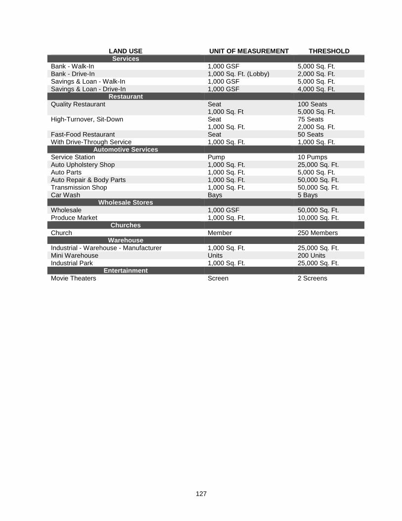
127
LAND USE UNIT OF MEASUREMENT THRESHOLD Services
Bank - Walk-In 1,000 GSF 5,000 Sq. Ft. Bank - Drive-In 1,000 Sq. Ft. (Lobby) 2,000 Sq. Ft. Savings & Loan - Walk-In 1,000 GSF 5,000 Sq. Ft. Savings & Loan - Drive-In 1,000 GSF 4,000 Sq. Ft.
Restaurant
Quality Restaurant Seat 1,000 Sq. Ft
100 Seats 5,000 Sq. Ft.
High-Turnover, Sit-Down Seat 1,000 Sq. Ft.
75 Seats 2,000 Sq. Ft.
Fast-Food Restaurant Seat 50 Seats With Drive-Through Service 1,000 Sq. Ft. 1,000 Sq. Ft.
Automotive Services
Service Station Pump 10 Pumps Auto Upholstery Shop 1,000 Sq. Ft. 25,000 Sq. Ft. Auto Parts 1,000 Sq. Ft. 5,000 Sq. Ft. Auto Repair & Body Parts 1,000 Sq. Ft. 50,000 Sq. Ft. Transmission Shop 1,000 Sq. Ft. 50,000 Sq. Ft. Car Wash Bays 5 Bays
Wholesale Stores
Wholesale 1,000 GSF 50,000 Sq. Ft. Produce Market 1,000 Sq. Ft. 10,000 Sq. Ft.
Churches
Church Member 250 Members Warehouse
Industrial - Warehouse - Manufacturer 1,000 Sq. Ft. 25,000 Sq. Ft. Mini Warehouse Units 200 Units Industrial Park 1,000 Sq. Ft. 25,000 Sq. Ft.
Entertainment
Movie Theaters Screen 2 Screens

128
Appendix 2: Traffic study requirements and study outline
Implemented: 10/10/2001 Revised: 01/01/1990
Typical Study Contents:
1. Introduction
1. Land Use, Site and Study Area Boundaries (provide map)
2. Existing and Proposed Site Uses
3. Existing and Proposed Uses in Vicinity of Site (provide map)
4. Existing and Proposed Roadways and Intersections (provide map)
2. Trip Generation and Design-Hour Volumes (provide table)
3. Trip Distribution (provide figure)
4. Trip Assignment (provide figure)
5. Existing and Projected Traffic Volumes (provide figure for each item)
1. AM Peak-Hour Site Traffic (including turning movements)
2. PM Peak-Hour Site Traffic (including turning movements)
3. AM Peak-Hour Total Traffic (including site-generated traffic and projected traffic)
4. PM Peak-Hour Total Traffic (including site-generated traffic and projected traffic)
5. Any Other Peak Hour Necessary for Complete Analysis
6. Total Daily Existing Traffic for Street System in Study Area
7. Total Daily Existing Traffic for Street System in Study Area and New Site Traffic
8. Total Daily Existing Traffic for Street System in Study Area Plus New Site Traffic and
Projected Traffic from Build-Out of Study Area Land Uses
6. Capacity Analysis (provide analysis sheets in appendices)
7. Traffic Signals (provide analysis sheets in appendices)
8. Traffic Accidents (optional) (provide collision diagrams and accident rate)
9. Conclusions
10. Recommendations
1. Proposed Recommended Improvements (provide sketches of improvements)
2. Volume/Capacity Analysis at Critical Points (provide analysis sheets in appendices)
3. Traffic Volume Proportions
NOTE: Information required on figures may be combined, provided that the information is clearly legible.
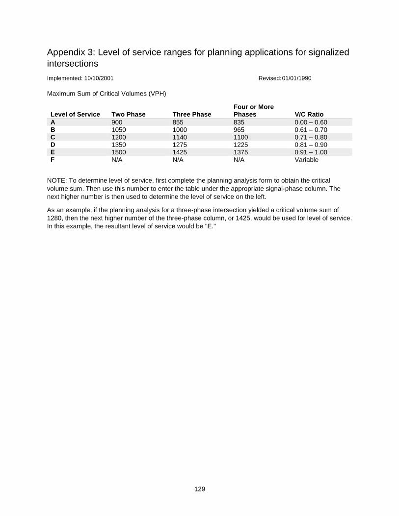
129
Appendix 3: Level of service ranges for planning applications for signalized
intersections
Implemented: 10/10/2001 Revised: 01/01/1990
Maximum Sum of Critical Volumes (VPH)
Level of Service Two Phase Three Phase Four or More Phases V/C Ratio
A 900 855 835 0.00 – 0.60 B 1050 1000 965 0.61 – 0.70 C 1200 1140 1100 0.71 – 0.80 D 1350 1275 1225 0.81 – 0.90 E 1500 1425 1375 0.91 – 1.00 F N/A N/A N/A Variable
NOTE: To determine level of service, first complete the planning analysis form to obtain the critical
volume sum. Then use this number to enter the table under the appropriate signal-phase column. The
next higher number is then used to determine the level of service on the left.
As an example, if the planning analysis for a three-phase intersection yielded a critical volume sum of
1280, then the next higher number of the three-phase column, or 1425, would be used for level of service.
In this example, the resultant level of service would be "E."
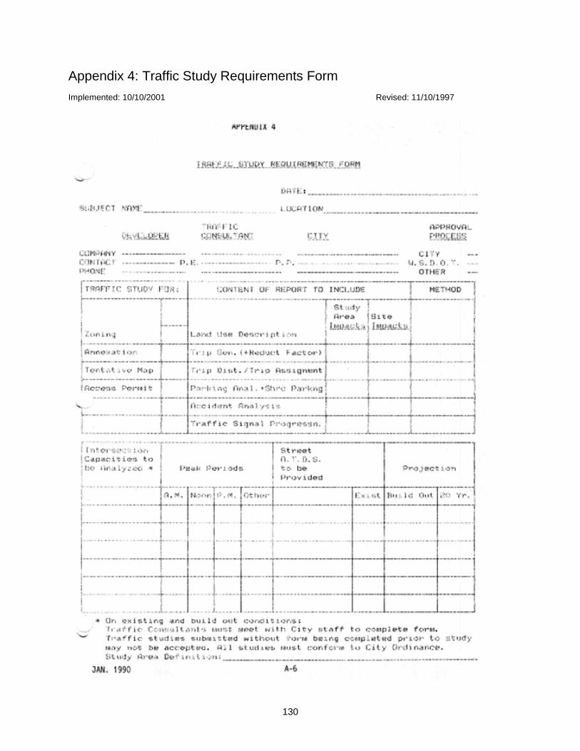
130
Appendix 4: Traffic Study Requirements Form
Implemented: 10/10/2001 Revised: 11/10/1997
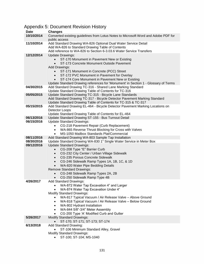
131
Appendix 5: Document Revision History Date Changes
10/10/2014 Converted existing guidelines from Lotus Notes to Microsoft Word and Adobe PDF for public access
11/10/2014 Add Standard Drawing WA-826 Optional Dual Water Service Detail Add WA-826 to Standard Drawing Table of Contents Add reference to WA-826 to Section 6-3.03.6 Water Service Transfers
12/12/2014 Update Drawings:
ST-170 Monument in Pavement New or Existing
ST-173 Concrete Monument Outside Pavement Add Drawings:
ST-171 Monument in Concrete (PCC) Street
ST-172 PVC Monument in Pavement for Overlay
ST-174 Core Monument in Pavement New or Existing Update Standard Drawing references for 'Monument' in Section 1 - Glossary of Terms
04/30/2015 Add Standard Drawing TC-316 - Shared Lane Marking Standard Update Standard Drawing Table of Contents for TC-316
05/05/2015 Update Standard Drawing TC-315 - Bicycle Lane Standards Add Standard Drawing TC-317 - Bicycle Detector Pavement Marking Standard Update Standard Drawing Table of Contents for TC-315 & TC-317
05/15/2015 Add Standard Drawing EL-464 - Bicycle Detector Pavement Marking Locations on Detector Loops Update Standard Drawing Table of Contents for EL-464
06/13/2016 Update Standard Drawing ST-155 - Bus Turnout Detail 06/15/2016 Update Standard Drawings:
CG-218 Pavement Repair (Curb Replacement)
WA-865 Reverse Thrust Blocking for Cross with Valves
MS-1050 Mailbox Standards Plat/Commercial 08/11/2016 Add Standard Drawing WA-803 Sample Tap Installation 08/30/2016 Update Standard Drawing WA-830 1" Single Water Service in Meter Box 09/12/2016 Update Standard Drawings:
CG-208 Type "E" Barrier Curb
CG-232 City Center / Urban Village Sidewalk
CG-235 Porous Concrete Sidewalk
CG-246 Sidewalk Ramp Types 1A, 1B, 1C, & 1D
WA-820 Water Pipe Bedding Details Remove Standard Drawings:
CG-248 Sidewalk Ramp Types 2A, 2B
CG-250 Sidewalk Ramp Type 4B 4/26/2017 Add Standard Drawings:
WA-872 Water Tap Excavation 4” and Larger
WA-874 Water Tap Excavation Under 4” Modify Standard Drawings:
WA-817 Typical Vacuum / Air Release Valve – Above Ground
WA-818 Typical Vacuum / Air Release Valve – Below Ground
WA-802 Hydrant Installation
WA-844 5/8”-3/4” Meter Assembly
CG-200 Type ‘A’ Modified Curb and Gutter 5/26/2017 Modify Standard Drawings:
ST-170; ST-171; ST-173; ST-174 6/13/2018 Add Standard Drawing:
ST-106 Minimum Standard Alley, Gravel Modify Standard Drawings:
ST-100; ST-104; MS-1040
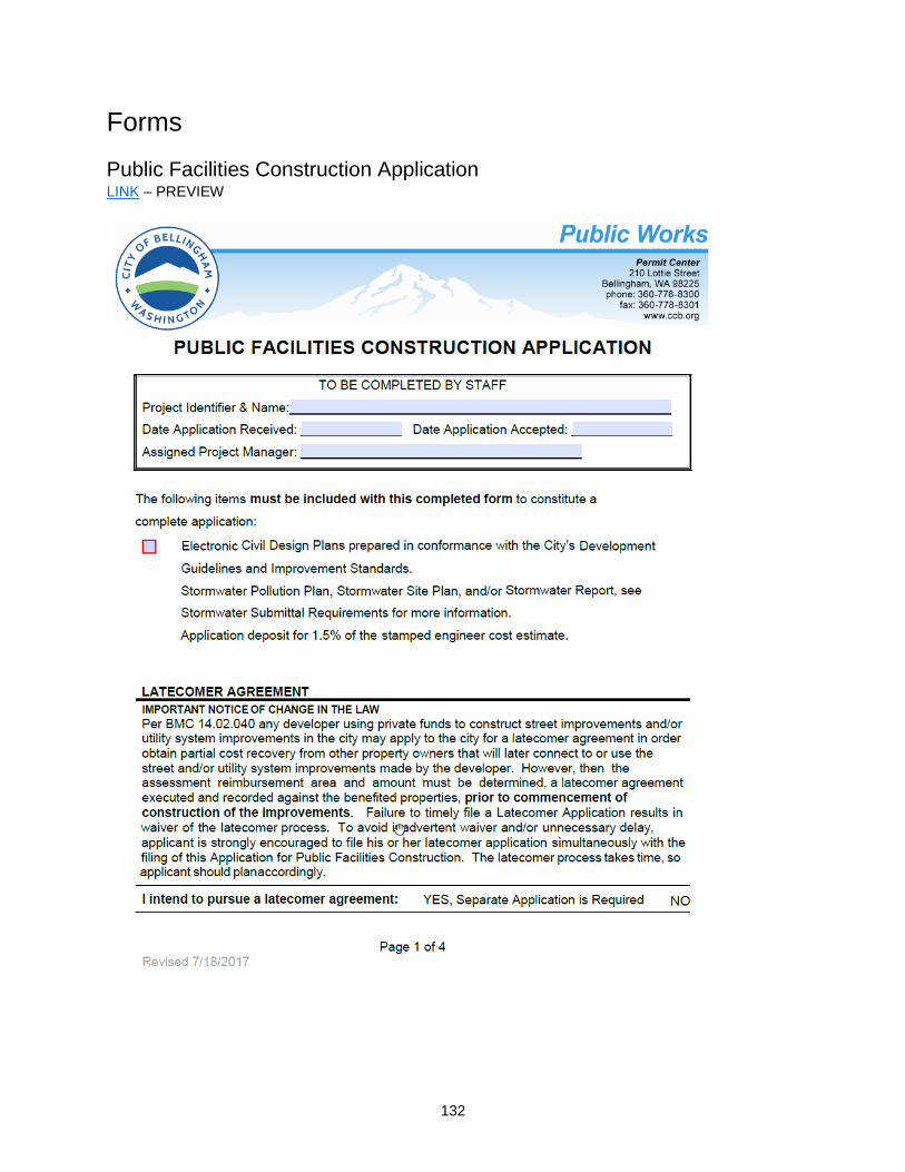
132
Forms
Public Facilities Construction Application LINK – PREVIEW

133
Web Sites
WSDOT Standards Website Link http://www.wsdot.wa.gov/Design/Standards/default.htm
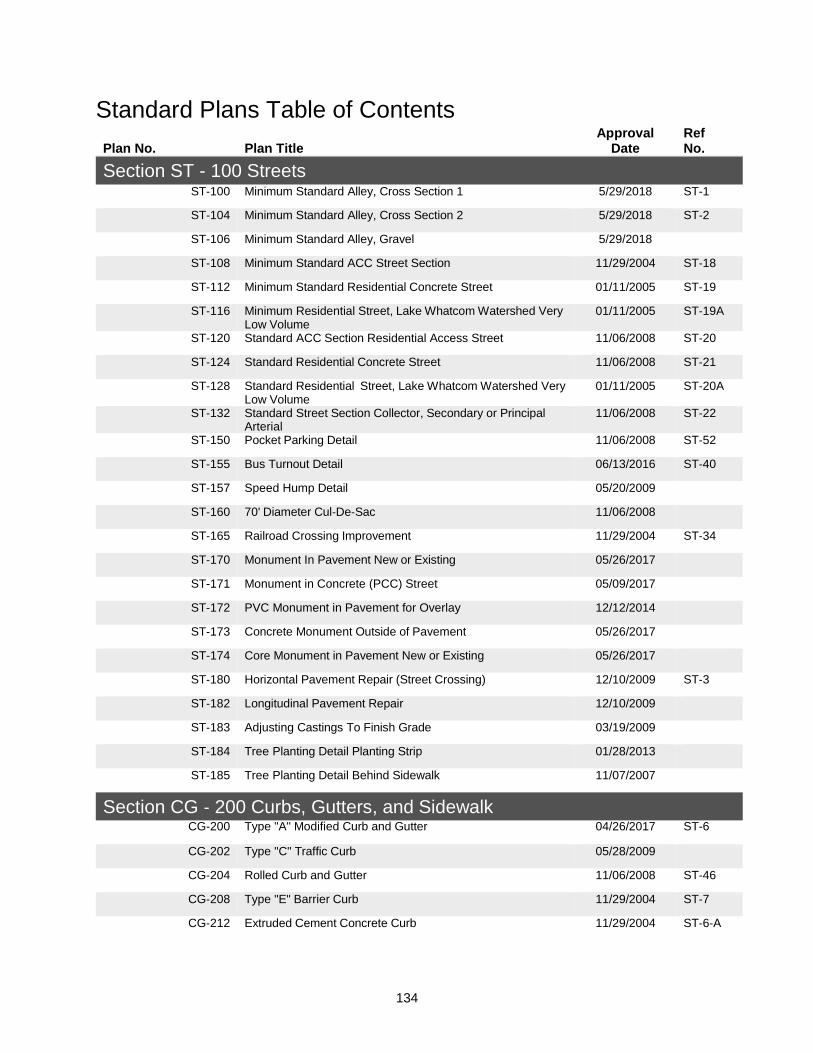
134
Standard Plans Table of Contents
Plan No. Plan Title Approval
Date Ref No.
Section ST - 100 Streets ST‐100 Minimum Standard Alley, Cross Section 1 5/29/2018 ST‐1
ST‐104 Minimum Standard Alley, Cross Section 2 5/29/2018 ST‐2
ST-106 Minimum Standard Alley, Gravel 5/29/2018
ST‐108 Minimum Standard ACC Street Section 11/29/2004 ST‐18
ST‐112 Minimum Standard Residential Concrete Street 01/11/2005 ST‐19
ST‐116 Minimum Residential Street, Lake Whatcom Watershed Very Low Volume
01/11/2005 ST‐19A
ST‐120 Standard ACC Section Residential Access Street 11/06/2008 ST‐20
ST‐124 Standard Residential Concrete Street 11/06/2008 ST‐21
ST‐128 Standard Residential Street, Lake Whatcom Watershed Very Low Volume
01/11/2005 ST‐20A
ST‐132 Standard Street Section Collector, Secondary or Principal Arterial
11/06/2008 ST‐22
ST‐150 Pocket Parking Detail 11/06/2008 ST‐52
ST‐155 Bus Turnout Detail 06/13/2016 ST‐40
ST‐157 Speed Hump Detail 05/20/2009
ST‐160 70' Diameter Cul‐De‐Sac 11/06/2008
ST‐165 Railroad Crossing Improvement 11/29/2004 ST‐34
ST‐170 Monument In Pavement New or Existing 05/26/2017
ST-171 Monument in Concrete (PCC) Street 05/09/2017
ST-172 PVC Monument in Pavement for Overlay 12/12/2014
ST‐173 Concrete Monument Outside of Pavement 05/26/2017
ST-174 Core Monument in Pavement New or Existing 05/26/2017
ST‐180 Horizontal Pavement Repair (Street Crossing) 12/10/2009 ST‐3
ST‐182 Longitudinal Pavement Repair 12/10/2009
ST‐183 Adjusting Castings To Finish Grade 03/19/2009
ST‐184 Tree Planting Detail Planting Strip 01/28/2013
ST‐185 Tree Planting Detail Behind Sidewalk 11/07/2007
Section CG ‐ 200 Curbs, Gutters, and Sidewalk CG‐200 Type "A" Modified Curb and Gutter 04/26/2017 ST‐6
CG‐202 Type "C" Traffic Curb 05/28/2009
CG‐204 Rolled Curb and Gutter 11/06/2008 ST‐46
CG‐208 Type "E" Barrier Curb 11/29/2004 ST‐7
CG‐212 Extruded Cement Concrete Curb 11/29/2004 ST‐6‐A
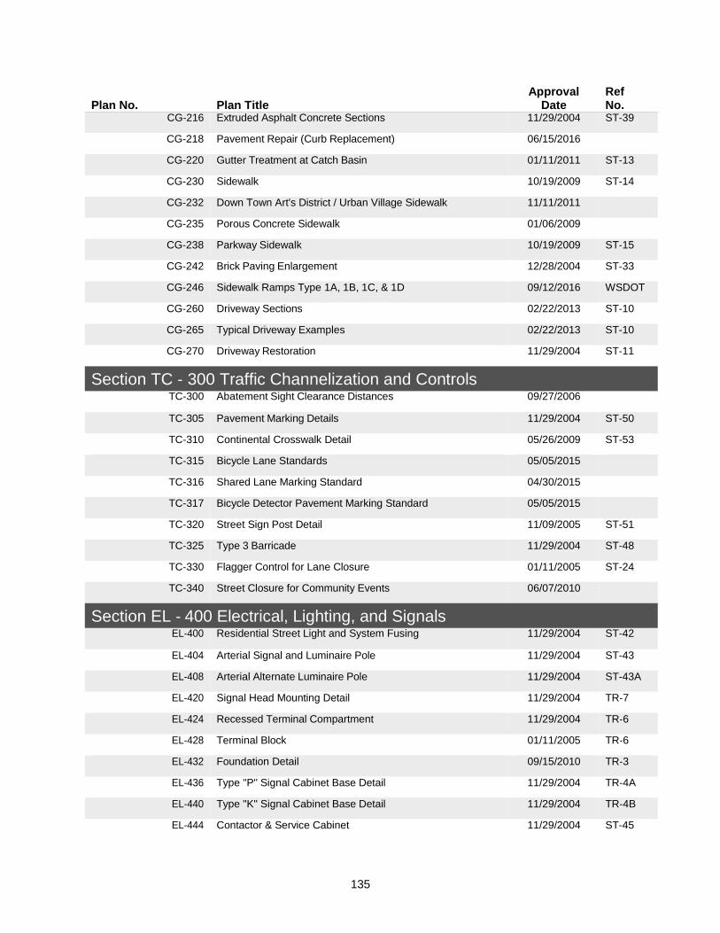
135
Plan No. Plan Title Approval
Date Ref No.
CG‐216 Extruded Asphalt Concrete Sections 11/29/2004 ST‐39
CG‐218 Pavement Repair (Curb Replacement) 06/15/2016
CG‐220 Gutter Treatment at Catch Basin 01/11/2011 ST‐13
CG‐230 Sidewalk 10/19/2009 ST‐14
CG‐232 Down Town Art's District / Urban Village Sidewalk 11/11/2011
CG‐235 Porous Concrete Sidewalk 01/06/2009
CG‐238 Parkway Sidewalk 10/19/2009 ST‐15
CG‐242 Brick Paving Enlargement 12/28/2004 ST‐33
CG‐246 Sidewalk Ramps Type 1A, 1B, 1C, & 1D 09/12/2016 WSDOT
CG‐260 Driveway Sections 02/22/2013 ST‐10
CG‐265 Typical Driveway Examples 02/22/2013 ST‐10
CG‐270 Driveway Restoration 11/29/2004 ST‐11
Section TC ‐ 300 Traffic Channelization and Controls TC‐300 Abatement Sight Clearance Distances 09/27/2006
TC‐305 Pavement Marking Details 11/29/2004 ST‐50
TC‐310 Continental Crosswalk Detail 05/26/2009 ST‐53
TC‐315 Bicycle Lane Standards 05/05/2015
TC-316 Shared Lane Marking Standard 04/30/2015
TC-317 Bicycle Detector Pavement Marking Standard 05/05/2015
TC-320 Street Sign Post Detail 11/09/2005 ST‐51
TC‐325 Type 3 Barricade 11/29/2004 ST‐48
TC‐330 Flagger Control for Lane Closure 01/11/2005 ST‐24
TC‐340 Street Closure for Community Events 06/07/2010
Section EL ‐ 400 Electrical, Lighting, and Signals EL‐400 Residential Street Light and System Fusing 11/29/2004 ST‐42
EL‐404 Arterial Signal and Luminaire Pole 11/29/2004 ST‐43
EL‐408 Arterial Alternate Luminaire Pole 11/29/2004 ST‐43A
EL‐420 Signal Head Mounting Detail 11/29/2004 TR‐7
EL‐424 Recessed Terminal Compartment 11/29/2004 TR‐6
EL‐428 Terminal Block 01/11/2005 TR‐6
EL‐432 Foundation Detail 09/15/2010 TR‐3
EL‐436 Type "P" Signal Cabinet Base Detail 11/29/2004 TR‐4A
EL‐440 Type "K" Signal Cabinet Base Detail 11/29/2004 TR‐4B
EL‐444 Contactor & Service Cabinet 11/29/2004 ST‐45

136
Plan No. Plan Title Approval
Date Ref No.
EL‐448 20 Conductor Signal Cable 11/29/2004 TR‐5
EL‐452 Quazite Service Box 11/29/2004 TR‐8
EL‐460 Type 1 Induction Loop 08/06/2010 TR‐2
EL‐462 Type 2 Induction Loop 08/06/2010 TR‐2A
EL-464 Bicycle Detector Pavement Marking Locations on Detector Loops
05/15/2015
Section DR ‐ 500 Drainage, Storm and Surface Water DR‐500 Thru‐Curb Inlet Frame and Grate with Vertical Curb
Installation 05/29/2014 ST‐12
DR‐502 Herringbone Gate for Catch Basins and Inlets 05/29/2014
DR‐505 Thru‐Curb Inlet Frame 05/29/2014 ST‐13A
DR‐510 Rolled Curb Frame and Grate 02/26/2009 ST‐47
DR‐515 Type 60A and 60B Outlet Trap 11/29/2004 ST‐12A
DR‐520 Cut Section Sidewalk Drain 11/29/2004 ST‐16
DR‐525 Residential Sidewalk Drain 11/29/2004 ST‐17
DR‐530 Storm Drain Side Service 04/28/2005
DR‐538 PVC Pipe Bedding Details 11/08/2007
DR‐539 Pipe Bedding Details for 2' or Less of Cover 11/08/2007
DR‐540 Storm Pipe End Section 11/29/2004 ST‐27
DR‐542 Restrictor Catch Basin Viewpoint Detail 10/26/2006
Section EC ‐ 600 Erosion Control EC‐600 Temporary Construction Exit ‐ Plat/Commercial 11/29/2004 EC‐1
EC‐605 Temporary Construction Exit ‐ Single Family 11/29/2004 EC‐2
EC‐610 Tire and Concrete Wash ‐ Plat/Commercial 11/29/2004 EC‐3
EC‐612 Tire Wash Sump Details 12/28/2004
EC‐615 Reinforced Silt Fence 11/29/2004 EC‐4
EC‐620 Catch Basin Insert 11/29/2004 EC‐5
EC‐625 Temporary Sediment Pond ‐ Type A 11/29/2004 EC‐6
EC‐630 Temporary Sediment Pond ‐ Type B 11/29/2004 EC‐7
EC‐635 Rock Check Dam 11/29/2004 EC‐8
EC‐640 Semi‐pervious Check Dam 11/29/2004 EC‐9
EC‐645 Erosion Control Check Dam Detail 11/29/2004 EC‐12
EC‐650 Plastic Covering for Slopes and Stockpiles 11/29/2004 EC‐10
EC‐655 Straw Rolls 11/29/2004 EC‐11
Section SS ‐ 700 Sanitary Sewer SS‐700 Manhole Standard 03/11/2010 SE‐6

137
Plan No. Plan Title Approval
Date Ref No.
SS‐704 Manhole Standard Ring and Cover 09/08/2011 SE‐6A
SS‐715 Inside Drop Sewer Manhole Connection 11/29/2004 SE‐5
SS‐716 Ductile Iron Outside Drop Sewer Manhole Connection 03/11/2010
SS‐717 Concrete Encased Outside Drop Sewer Manhole Connection 03/17/2010
SS‐720 8" Clean Out 05/29/2014 SE‐1
SS‐730 Sanitary Side Sewer 05/29/2014
SS‐735 Side Sewer Clean‐Out Lid 05/29/2014
SS‐740 Sanitary Banded Tapping Tee 04/15/2009 SE‐2
SS‐750 PVC Pipe Bedding Detail 04/22/2010 SE‐4
SS‐760 Pipe Anchor 11/29/2004 SE‐7
SS‐790 Typical Sewer Drawing of Record (Including Services) 01/11/2005 SE‐3
Section WA ‐ 800 Water Distribution WA‐802 Hydrant Installation 04/20/2017 WA‐1
WA-803 Sample Tap Installation 08/11/2016
WA‐804 Fire Hydrant Bollard Detail 12/28/2004
WA‐810 Blow‐Off for Future Water Main Extensions 02/03/2010 WA‐3
WA‐814 2" Blow‐Off, No Further Extension 02/03/2010 WA‐4
WA‐817 Typical Vacuum/Air Release Valve ‐ Above Ground 11/30/2011
WA‐818 Typical Vacuum/Air Release Valve ‐ Below Ground 11/30/2011
WA‐820 Water Pipe Bedding Details 03/01/2011
WA‐824 1" Single Water Service Detail 02/07/2014 WA‐9
WA-826 Optional Dual Water Service Detail 11/10/2014
WA‐828 Typical Water Service on Private Property 12/28/2004 WA‐7
WA‐830 3/4" and 1" Single Water Service In Meter Box 02/03/2010
WA‐834 Temporary Construction Water With Yard Hydrant 05/26/2009
WA‐836 Temporary Construction Water With Hose Bibb 05/26/2009
WA‐840 1 1/2" Meter Assembly 12/28/2004 WA‐10
WA‐842 2" Meter Assembly 12/28/2004 WA‐11
WA‐844 5/8" ‐ 3/4" Meter Assembly 04/20/2017
WA‐846 Number 2 Meter Box 05/17/2005 WA‐12
WA‐848 Number 2 Meter Box Modifications 09/17/2007 WA‐12
WA‐850 Number 3 Flat Top Meter Box 07/19/2012 WA‐9
WA‐858 Pressure Test Charge Manifold 03/19/2012 WA‐2
WA‐860 Thrust Block ‐ Elbow 01/11/2005 WA‐5
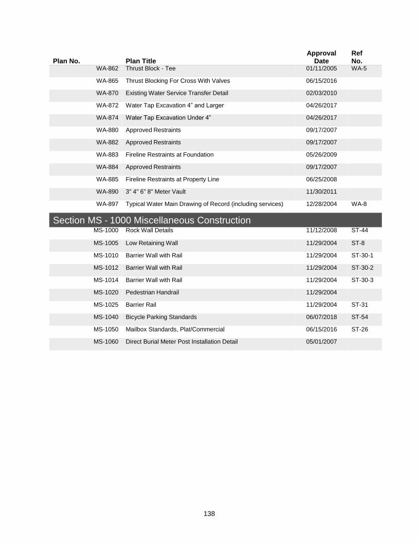
138
Plan No. Plan Title Approval
Date Ref No.
WA‐862 Thrust Block ‐ Tee 01/11/2005 WA‐5
WA‐865 Thrust Blocking For Cross With Valves 06/15/2016
WA‐870 Existing Water Service Transfer Detail 02/03/2010
WA-872 Water Tap Excavation 4” and Larger 04/26/2017
WA-874 Water Tap Excavation Under 4” 04/26/2017
WA‐880 Approved Restraints 09/17/2007
WA‐882 Approved Restraints 09/17/2007
WA‐883 Fireline Restraints at Foundation 05/26/2009
WA‐884 Approved Restraints 09/17/2007
WA‐885 Fireline Restraints at Property Line 06/25/2008
WA‐890 3" 4" 6" 8" Meter Vault 11/30/2011
WA‐897 Typical Water Main Drawing of Record (including services) 12/28/2004 WA‐8
Section MS ‐ 1000 Miscellaneous Construction MS‐1000 Rock Wall Details 11/12/2008 ST‐44
MS‐1005 Low Retaining Wall 11/29/2004 ST‐8
MS‐1010 Barrier Wall with Rail 11/29/2004 ST‐30‐1
MS‐1012 Barrier Wall with Rail 11/29/2004 ST‐30‐2
MS‐1014 Barrier Wall with Rail 11/29/2004 ST‐30‐3
MS‐1020 Pedestrian Handrail 11/29/2004
MS‐1025 Barrier Rail 11/29/2004 ST‐31
MS‐1040 Bicycle Parking Standards 06/07/2018 ST‐54
MS‐1050 Mailbox Standards, Plat/Commercial 06/15/2016 ST‐26
MS‐1060 Direct Burial Meter Post Installation Detail 05/01/2007