
Development Glass Ceramics from Blast Furnace Slagethesis.nitrkl.ac.in/6078/1/110CR0539-1.pdf ·...
41
Development Glass Ceramics from Blast Furnace Slag A THESIS SUBMITTED IN PARTIAL FULFILLMENT OF THE REQUIREMENTS FOR THE DEGREE OF Bachelor in technology In Ceramic Engineering BY Sumit Kumar Aman Roll no.-110CR0539 Under the guidance of Prof. Sumit Kumar Pal Department of Ceramic Engineering National Institute of Technology, Rourkela 2014
Transcript of Development Glass Ceramics from Blast Furnace Slagethesis.nitrkl.ac.in/6078/1/110CR0539-1.pdf ·...

Development Glass Ceramics from Blast
Furnace Slag
A THESIS SUBMITTED IN PARTIAL FULFILLMENT
OF THE REQUIREMENTS FOR THE DEGREE OF
Bachelor in technology
In
Ceramic Engineering
BY
Sumit Kumar Aman Roll no.-110CR0539
Under the guidance of
Prof. Sumit Kumar Pal
Department of Ceramic Engineering
National Institute of Technology, Rourkela
2014

2
DECLARATION
I am Sumit Kumar Aman, a student of Department of Ceramic Engineering,
National Institute of Technology Rourkela bearing Roll Number-110CR0539
hereby certify that my B.tech Project Report entitled “Development of Glass
Ceramic from Blast furnace Slag”, under the guidance of Prof. Sumit
Kumar Pal at National Institute of Technology, Rourkela. This is a record of
bona fide work carried out by me and the results presented in the Project Report
have not copied from any source. The results presented in this Project Record not
have submitted to any other University or institute for the award of any other
certificate or degree.
ROURKELA SUMIT KUMAR AMAN
DATE: 12/05/2014 DEPARTMENT OF CERAMIC ENGINEERING
NIT, ROURKELA

3
NATIONAL INSTITUTE OF TECHNOLOGY
ROURKELA
CERTIFICATE
This is to certify that the Project Report entitled “Development of Glass-
Ceramics from blast furnace slag”, being submitted by Mr. Sumit Kumar
Aman, Department of Ceramic Engineering, National Institute of Technology
Rourkela, under the requirement for the Degree of Bachelor of Technology in
Ceramic Engineering is a record of bona fide work carried out by him, under my
guidance and supervision. The results enclosed in this report have been verified
and found to be satisfactory.
The results presented in this Project Report have not been submitted to any other
University or Institute for the Award of any other certificate or degree.
ROURKELA
DATE: 12/05/2014

4
ACKNOWLEDGMENT
With deep respect, I avail this opportunity to express my gratitude to Dr.
Sumit Kumar Pal, Assistant Professor, National Institute of Technology,
Rourkela for his inspiration and guidance and valuable suggestion throughout
this research work. It would have been impossible on my part to come out
with this project report without him. I would like to express my gratitude to
Dr. S. Pratihar (HOD), Ceramic Engineering for permitting to carry out my
project. I would like to take this opportunity to thank all the faculty members
of Ceramic engineering Department namely Dr. Japes Bera, Dr. B.B. Nayak,
Dr. D. Sarkar, Mr A. Choudhury, Dr. S. Behera , Dr. R. Mazumder, Dr. R.
Sarkar, Dr. S. Das gupta, and Dr. S. Bhattacharyya. I would also take this
opportunity to express my gratitude to the non-teaching staff Bapi sir, Mr
Arvind Kumar, and Ezhil Venuswaran (PhD. Scholars) for the help and
support in carrying out experiments and providing every sort of help possible.
SUMIT KUMAR AMAN
DEPARTMENT OF CERAMIC ENGINEERING
NIT ROURKELA

5
Contents
Abstract………………………………………………………7
CHAPTER 1 : INTRODUCTION
1.1 Introduction……………………………………....9
CHAPTER 2 : LITERATURE REVIEW
2.1 Literature Review………………………………..12
CHAPTER 3 : EXPERIMENTAL PROCEDURE
3.1 Chemical analysis ……………………………….16
3.2 Batch preparation………………………………..17
3.3 Melting of batch………………………………….18
3.4 Bulk density……….……………………………..18
3. 5 Three point Bending ……………………………19
3.6 Vickers hardness…………………………………20
3.7 Compressive strength (CCS)….………………….21
3.8 FESEM…………………………………………….23
CHAPTER 4: RESULT AND DISCUSSION
4.1 Determination of melting temperature…………..25

6
4.2 Preparation of glass ceramics…………………..26
4.3 Hardness of glass………………………………29
4.4 Bulk density of glass sample…………………..30
4.5 Flexural strength of glass……………………...31
4.6 Hardness of glass ceramics……………………32
4.7 Bulk density of glass ceramic…………………33
4.8 Compressive strength of glass ceramics….......35
4.9 Dilatometer test of glass ceramic…………......36
4.10 Microstructure observation by FESEM……...37
CHAPTER 5: CONCLUSION
5.1 Conclusion………………………………………39
REFERENCE……………………………………….40

7
Abstract
Glass ceramics have a wide range of applications in today’s world. The production of glass
ceramics from industrial waste such as fly ash, red mud, blast furnace slag gaining more
importance now a days because of their availability and low cost. In the present work an attempt
has been made to produce glass ceramic with high alumina content using blast furnace slag.
Generally alumina is very difficult to melt. To produce base glass for glass ceramic from blast
furnace slag, an additional low melting phase which aid in dissolving the alumina can be
provided by blast furnace slag. Blast furnace slag is generally produced at the temperature range
1300oC to 1400
oC. High alumina content glass with alumina percentage as high as 30% (more
alumina content in E-glass) requires melting temperature as high as 1600oC. Therefore using
blast furnace slag as one of the main constituents can help in reducing the melting temperature of
the precursor glass prior to glass ceramic production. More over high alumina content in the
glass as well as in glass ceramic can enhance different physical properties, like high mechanical
strength, high durability, low thermal expansion co efficient which are very suitable for cooktop
application. In the present work an attempt has been made glass ceramics from blast furnace with
alumina content 32% . Glasses are melted at 1400oC. For glass ceramic production glasses are
heat treated at 750oC, 850
oC and 950
oC. Glass ceramic products are characterize by Vickers
Hardness, Bulk density measurement, Flexural strength , Compressive strength , Dilatometer test
and FESEM.

8
CHAPTER: 1
INTRODUCTION

9
INTRODUCTION
The industrial waste is one of the major environmental problem worldwide. Blast furnace slag is
waste of iron and steel making plant[1]. In various countries, the drawback of number of
dumping landfill sites and the general discarding methods has rendered the environment
unfriendly[3].To reduce this problem waste must be re used or recycled which is produced by
industry. So that raw material cost will be minimize as well as for environment protection[2].
Using blast furnace slag as raw material for precursor glass prior to glass ceramization can be a
effective way to recycle the blast furnace slag..
Glass ceramics are formed by controlled heat treatment, with parent Glass along with other
desirable composition. The glass is first melt quenched then it is heat treated with controlled
heating rate in various time interval. With controlled heat treatment nucleation takes place
homogeneously followed by growth mechanism. Through this method with controlled
crystallization various property improvement can be achieved.
The blast furnace slag formed in the process of formation of pig iron from iron ore[6], it is
obtained by water quenching or air quenching ,Due to rapid cooling blast furnace slag mostly
found in glassy phase and due to water quenching they are eventually form in granular mode.
And it is easy to make in a powder form. Generally blast furnace slag contains residue of coke,
limestone’s fluxes or serpentine and other materials like mixture of metal oxides and silicon
dioxide [2]. If the molten slag cooled quickly in high pressure water zone, fine grain of slag can
be formed. Generally the composition of blast furnace slag contains SiO2 , Al2O3 , CaO , MgO ,
Fe2O3 in major amount. Since this is a slag so there can be anything in the composition of blast

10
furnace slag that may be CaF2 , MnO , Na2O , TiO2. Properties of final product may vary with
the slag composition because slag generated from different industry may be different from each
other. Dissimilar procedures of Slag products vary according to the technique use in cooling the
molted slag.
In the present work an attempt has been made to produce glass ceramic from blast furnace slag
with high alumina content. High alumina content in glass ceramic can improve different
properties in glass ceramic. With high alumina content a glass ceramic is expect to have high
mechanical strength, high corrosion resistance and low thermal expansion coefficient, which will
be very suitable for cook-top application.

11
CHAPTER: 2
LITERATURE REVIEW
12
Literature review
Low cost Glass ceramics from molted Blast furnace slag have been studies by Zhao et.al. [1],
wherein as a raw material used molten blast furnace slag and silica(SiO2), low energy
consumption as compare to conventional method because of use of molten slag. In this high ratio
of blast furnace slag approximate 90%. The effect of CaF2 (microstructure) studied by XRD,
DSC and SEM, and bending strength of measured by Three point bending method. The bending
strength of the glass–ceramics was about 45.8 MPa. If CaF2 add then it’s strength increased
greatly to 120 Mpa.
Glass–ceramics made from blast-furnace slag by a conventional sintering process. Hongyu Liu
et.al.[2] studied the properties of glass ceramics which is made by blast furnace slag and potash
feldspar as additives. It shows that 5 wt% feldspar improve the sintering properties, And 5.2 GPa
of micro hardness and bending strength was greater than 85 MPa as well as absorption of water
below 0.14% obtained.
Blast furnace slag converts into Glass-Ceramics materials Francis [3] studied SEM , XRD and
DTA analysis. The crystalline phases was found as gehlenite, diopside pyroxene and barium
aluminium silicate. The maximum density found at 900 oC. At temperature of 1050
oC acicular
and dendritic morphology have been identified. A slight variation in peak crystallization
temperature with particle size indicated a bulk crystallization mechanism.
The effect of composition of glass ceramics on crystallization behavior made by blast furnace
Slag Mihailova et.al [4] studied on the composition blast furnace slag 68-80 wt% , kaolin, Al2O3
And TiO2 . Glass ceramics made by sintering process of glass powder at 1000 oC. The crystalline
phases was identified to be anorthite melilite, anorthite and pyroxene. The ratio between

13
crystalline phases depends on chemical composition of the glass.
SiO2-CaO-Na2O-MgO based glass ceramics sintering behaviour on adding calcium fluoride
Mirhadi et.al. [5] reported when increases content of CaF2, decreases the crystallization
Temperature of glass and also decreases the strength of crystallization peak temperature. Till
Addition of 6.0 mol% of CaF2 sinterability improved. This sample shows maximum density by
sintering at 950 oC.
Phase separation mechanism in blast furnace slag glass phase Yu et.al. [6] reported that A
necessity of development for the phase separation of the blast furnace slag glass phase was this
the composition of blast furnace slag detects in the existing point region of melilite and any
silicate with Qo units in CaO-MgO-Al2O3-SiO2 system. One with chemical composition of larger
ratio of (CaO+MgO)/(SiO2+Al2O3) would be more encouraging to meet the condition. Melilite
was categorized as sorosilicate, but it was a layer structure with high DOP for the special melilite
units, a 5- membered ring made of Si2O7 + MgO4 or (Si,Al)2O7 +AlO7 , this plays the lead role of
the phase separation.
Volume Nucleation of crystal based on blast furnace slag in glass Sycheva et.al.[7] studied that
by blending metallurgical slag with silicon dioxide the nucleation of crystals in glass obtained. It
was shown that the first crystalline phase in a volume crystallizing glass was perovskite (CaO ⋅
SiO2); in this phase a nucleation of the main phase occurs: melilite (solid solution of gehlinite
2CaO ⋅ Al2O3 ⋅ SiO2 in akermanite 2CaO ⋅ MgO ⋅ 2SiO2).
G.A. Khater [8] observed that the presence of Cr2O3, TiO2, CaF2 and LiF enhance the
crystallizability of the glass. Cr2O3 and TiO2 are better promoter for homogeneous nucleation as
well as for the formation of extremely fine-grained microstructure of aluminous pyroxene and
magnetite than LiF and CaF2.

14
Zhong-jie Wang et. al[9] studied the crystallization behavior of glass ceramic formed by mixture
of BF lag nickel slag and quartz sand with the help of differential scanning calorimetry (DSC),
X-ray diffraction (XRD) and field emission scanning electron microscope (FESEM) in his paper.
When the glass is heated up to 700 °C then a large number of tiny spherical crystals forms and
the radial crystals form when the glass is heated up to 820 °C. The crystallization temperature is
found to be 860 °C. Crystals of diopside (CaMg(Si,Al,Fe)2O6) and hedenbergite
(CaFe(Si,Al,Fe)2O6) are observed as final phases and the activation energy of crystallization is
found to be about 201.28 kJ/mol.

15
CHAPTER: 3
EXPERIMENTAL
PROCEDURE
16
3.1 Chemical analysis
Taken 0.5203 gm of sample (Blast furnace slag) in platinum crucible and 10 gm of Na2CO3 and
added few bit NaOH . Mixed it properly and fuse the mass at 1000oC for 1 hrs. cool it down
transfer the mass in 100 cc HCL taken in a 250 ml beaker. Kept the beaker at hot plate for
overnight till complete drying (Beaking) then add 50cc 1:1 HCL and warm it and after this
filtrate the mass through WHATMAN 540 filter paper , collect the filtrate 1 in a 250ml
volumetric flask. Take the residue in a pre-weighted crucible fire at 1000oC for 1 hrs. residue is
reported as silica.
Determination of Mixed oxide (Fe2O3 and Al2O3):
Make the volume of a filtrate 1 upto the mark taken 50cc of filtrate 1 in a 250 ml beaker added
few drops of Methyl red indicator (color red in acidic medium), added ACC buffer till medium is
alkaline (yellowish green color) warm it and filtrate through WHATMAN 541 filter paper collect
filtrate 2 in a 250cc volumetric flask fire the residue at 1150oC for 1 hrs. report the residue as
Mixed oxide.
Determination of Fe2O3:
Taken 10ml of filtrate 1 in 250ml conical flask added 10cc of ammonium thiocyanate solution
color become blood red. Filtrate it against standard murcurious Nitrate solution with vigorous till
color less end point. Calculate the amount of iron oxide from Ag2(NO3) consumed report the
difference from the mixed oxide as Al2O3 .
Determination of CaO and MgO:
Make up the volume of filtrate 2 and take 10cc of filtrate 2 in 250ml conical flask add 10cc AAC
buffer and a pinch of Eriochrome black T(EBT) indicator color become wine red titrate it

17
standard EDTA solution (0.01M) till sky blue end point. Calculate the amount of CaO and MgO
from EDTA consumed.
Determination of CaO:
Taken 10ml of filtrate of filtrate in conical flask added NaOH solution (10%) and add a pinch of
P&R indicator color become light violet titrate it against standard EDTA. Report CaO from the
volume of EDTA consumed. . The chemical composition of blast furnace slag after analysis
composition was found as:
SiO2 (wt%) Al2O3 (wt%) CaO (wt%) MgO (wt%) Fe2O3 (wt%)
35.29 27.58 26.94 8.71 1.15
Table-3.1 Composition of blast furnace slag
3.2 Batch preparation
The project started with the batch calculation and finding the chemical composition of blast
furnace slag. Blast furnace slag (provided by RSP Rourkela) was milled in Pulverizer mill for
about 1 hours. Blast furnace slag converts into fine powder .Batch composition fixed as:
B F SLAG Al2O3 CaF2 B2O3 TiO2
Batch-1(Wt%) 80 10 5 4 1
Batch-2(Wt%) 80 10 5 4.5 0.5
Table-3.2 Batch composition
As fixed the batch composition, two batches were made in proper manner and mixed the batch
perfectly.

18
Final composition of glass-ceramics:
SiO2 Al2O3 CaO MgO CaF2 Fe2O3 B2O3 TiO2
Batch-1(wt%) 28.23 32.06 21.55 6.97 5 0.92 4 1
Batch-2(wt%) 28.23 32.06 21.55 6.96 5 0.92 4.5 0.5
Table-3.3 composition of glass ceramics
3.3 Melting of batch
After fixing the melting temperature taken both batch separately in silimanite crucible and goes
for melting at temperature of 1400oC soaking time was 1 hours. And heating rate was on control
mode. On completion of scheduled heating pored that melt on graphite plate and annealing for 3
hours. Two glass plate made from the above mentioned method and named as batch-1 and batch-
2.
3.4 Bulk density
Bulk Density (B.D) is defined as the material present in a given volume that is, it is the ratio of
the mass of a material to its bulk volume, i.e. the volume of the given material plus all the pores
within it. An increase in bulk density of a given glass ceramic increases its volume stability, its
heat capacity, its mechanical and thermomechanical property as well as resistance to corrosion.
It is measured by Evacuation method. First of all, the made glass and glass ceramic samples is
weighed and noted down. This weight is dry weight (D). The dry specimen is placed in empty
desiccator and then is evacuated to remove the trapped air. Now samples are suspended in
19
immersion liquid and weighed. This is suspended weight(S). Then the test sample is dried using
a blotting paper. After which soaked weight (W) is calculated.
Calculation:
B.D. = [Dry Weight / (Soaked Weight – Suspended Weight)]
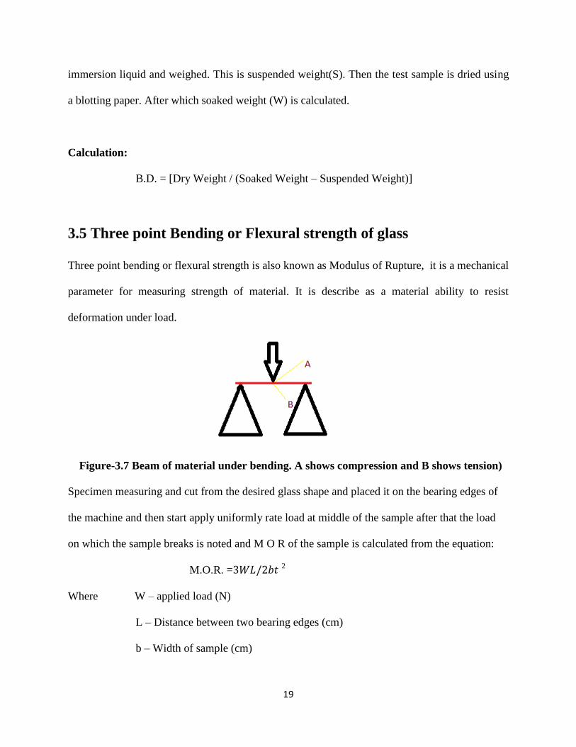
3.5 Three point Bending or Flexural strength of glass
Three point bending or flexural strength is also known as Modulus of Rupture, it is a mechanical
parameter for measuring strength of material. It is describe as a material ability to resist
deformation under load.
Figure-3.7 Beam of material under bending. A shows compression and B shows tension)
Specimen measuring and cut from the desired glass shape and placed it on the bearing edges of
the machine and then start apply uniformly rate load at middle of the sample after that the load
on which the sample breaks is noted and M O R of the sample is calculated from the equation:
M.O.R. = 2
Where W – applied load (N)
L – Distance between two bearing edges (cm)
b – Width of sample (cm)

20
t – Thickness of sample (cm).
3.6 Vickers hardness
Hardness is the property of a material that allows resistance to plastic deformation, by
penetration. Hardness may also refer to resistance to bending, rubbing, scratch or cutting.
In Vickers hardness test method, the test material is indented with a diamond indenter, in the
form of a right pyramid with a square base and an angle of 136 degrees between opposite faces
and a load of 0.3 Kgf is applied. The load was applied for 4 seconds. The two diagonals of the
indentation in the surface of the material after removal of the load are measured with a
microscope attached to testing machine and their average is calculated. The area of the
indentation is calculated. The Vickers hardness is obtained by dividing the kgf load by the square
mm area of indentation.
3.8 Vickers hardness testing machine
Calculation:
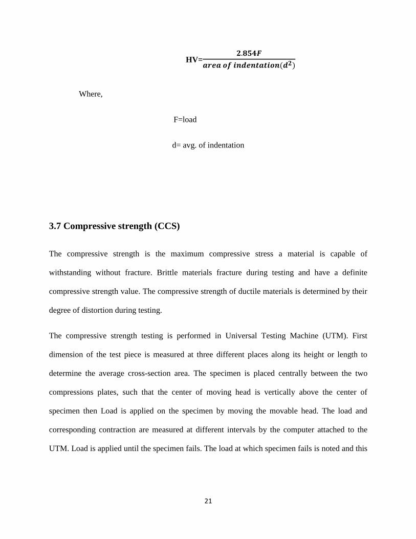
21
HV=
Where,
F=load
d= avg. of indentation
3.7 Compressive strength (CCS)
The compressive strength is the maximum compressive stress a material is capable of
withstanding without fracture. Brittle materials fracture during testing and have a definite
compressive strength value. The compressive strength of ductile materials is determined by their
degree of distortion during testing.
The compressive strength testing is performed in Universal Testing Machine (UTM). First
dimension of the test piece is measured at three different places along its height or length to
determine the average cross-section area. The specimen is placed centrally between the two
compressions plates, such that the center of moving head is vertically above the center of
specimen then Load is applied on the specimen by moving the movable head. The load and
corresponding contraction are measured at different intervals by the computer attached to the
UTM. Load is applied until the specimen fails. The load at which specimen fails is noted and this

22
is maximum force (Fmax) and the surface area of the base is calculated and then compressive
strength can be calculated.
Fig. 3.9 Universal Testing Machine (UTM
Calculation:
Compressive Strength =
Where, is the force applied for failure and L1×L2 is the area of the base of specimen.

23
3.8 Microstructure observation by FESEM
The FESEM is generally used to the analyze the grain-shape, grain-size, packing of grains, grain
boundary, pore shape and size new phases etc. The prepared samples has been cut into small
pieces. The surface of testing specimen is polished by three consecutive polishing (6µm, 3 µm,
and 1 µm cloth) using diamond suspension spray. Ultra cleaning of samples is performed after
each polishing. After that carbon coating has been done and loaded into the sample holders and
FESEM analysis has been performed.

24
CHAPTER: 4
RESULTS
AND
DISCUSSION

25
4.1 Determination of melting temperature of precursor glass
Temperature at which the materials changes solid to liquid stage is known as melting
temperature. To find melting temperature of the glass batch, both batches named as batch-1 and
batch-2 with composition as mentioned in table-2. After making two batches, made some piece
plate through hydraulic pressing machine and using die-punch. When plate made all the sample
put into furnace one by one at different temperature and different soaking time and observe,
Figure-4.1 At temperature 1100,1200,1300 oC

26
Figure-4.2 At temperature 1300, 1350, 1400oC
As shown in figure 4.1, at 1100oC sintering occurs but it doesn’t form any molten phase, while at
1200oC some phases softened and eutectics started forming. At 1300
oC partial melting occurs
and eutectic formation is complete. At 1300oC, the soaking time was increased and due to that
some more melting phases formed and some bubbles start coming out from the batch. At
1350oC the batch doesn’t melt completely because of the presence of high alumina in the
compositions but bubble formation continues. The bubbles try to come out but due to the high
viscosity of melt they do not come out completely. At 1400oC batch melts completely and form

27
glassy phase. The bubbles escape completely from the melt. This helps in concluding that
melting point of batches was 1400oC. Another observation that was made was that the color of
the batches changed from white to brownish during the melting process. This was due to the
effect of the impurities present in the blast furnace slag used. Since 80% slag was used in the
composition, the colour change was significant.
4.2 Glass-ceramization
To prepare the glass ceramic as prepared glasses were heat treated Preparation at the temperature
750 oC, 850
oC, 950
oC with a soaking of 4 hours. There significant changes in appearance
observe after every heat treatment.
Fig.-4.3 Glass reheated at 750 oC
It has been observed that after heat treatment at 750oC for 4 hours there is change in appearance
in the glass samples. Glass has lost its transparency and it became translucent. The translucency
in the glass samples are due to scattering of light from the glass samples . So it is evident that
after heat treatment there is nucleation took place homogeneously due to presence of TiO2 which
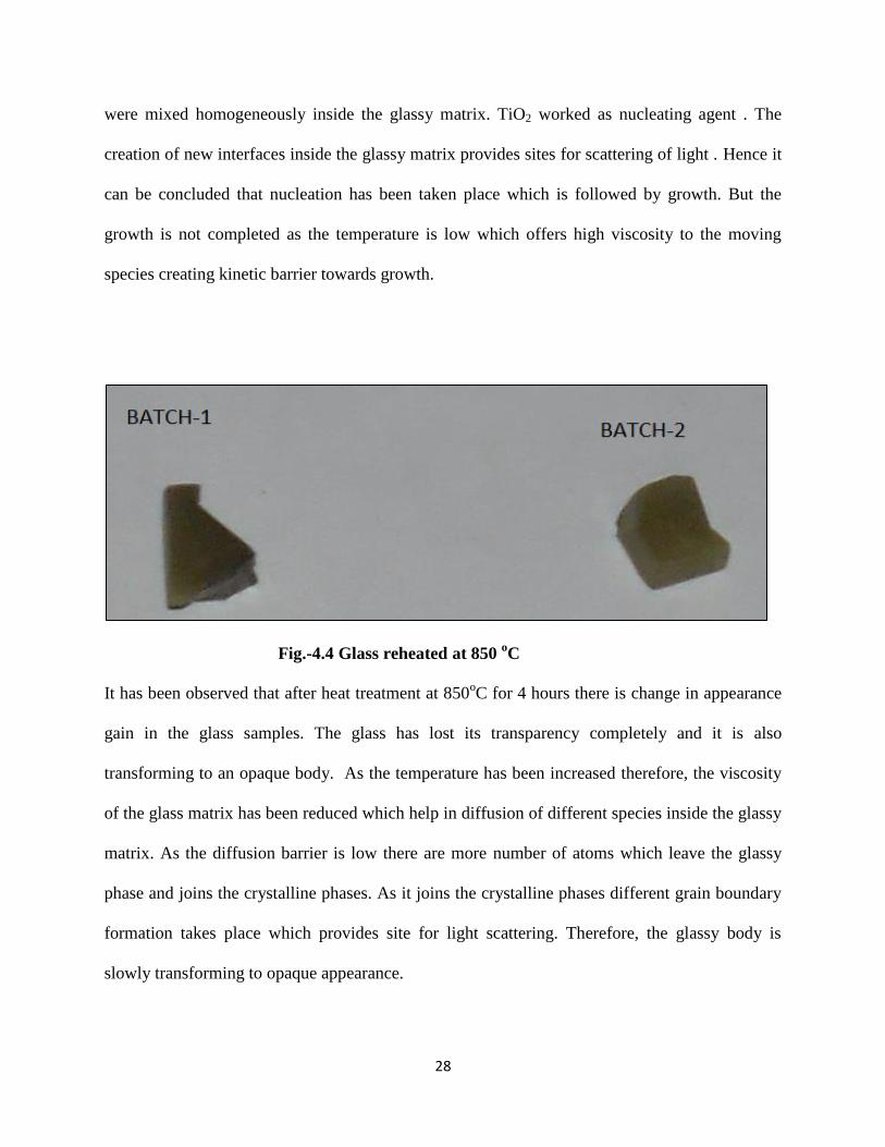
28
were mixed homogeneously inside the glassy matrix. TiO2 worked as nucleating agent . The
creation of new interfaces inside the glassy matrix provides sites for scattering of light . Hence it
can be concluded that nucleation has been taken place which is followed by growth. But the
growth is not completed as the temperature is low which offers high viscosity to the moving
species creating kinetic barrier towards growth.
Fig.-4.4 Glass reheated at 850 oC
It has been observed that after heat treatment at 850oC for 4 hours there is change in appearance
gain in the glass samples. The glass has lost its transparency completely and it is also
transforming to an opaque body. As the temperature has been increased therefore, the viscosity
of the glass matrix has been reduced which help in diffusion of different species inside the glassy
matrix. As the diffusion barrier is low there are more number of atoms which leave the glassy
phase and joins the crystalline phases. As it joins the crystalline phases different grain boundary
formation takes place which provides site for light scattering. Therefore, the glassy body is
slowly transforming to opaque appearance.
29
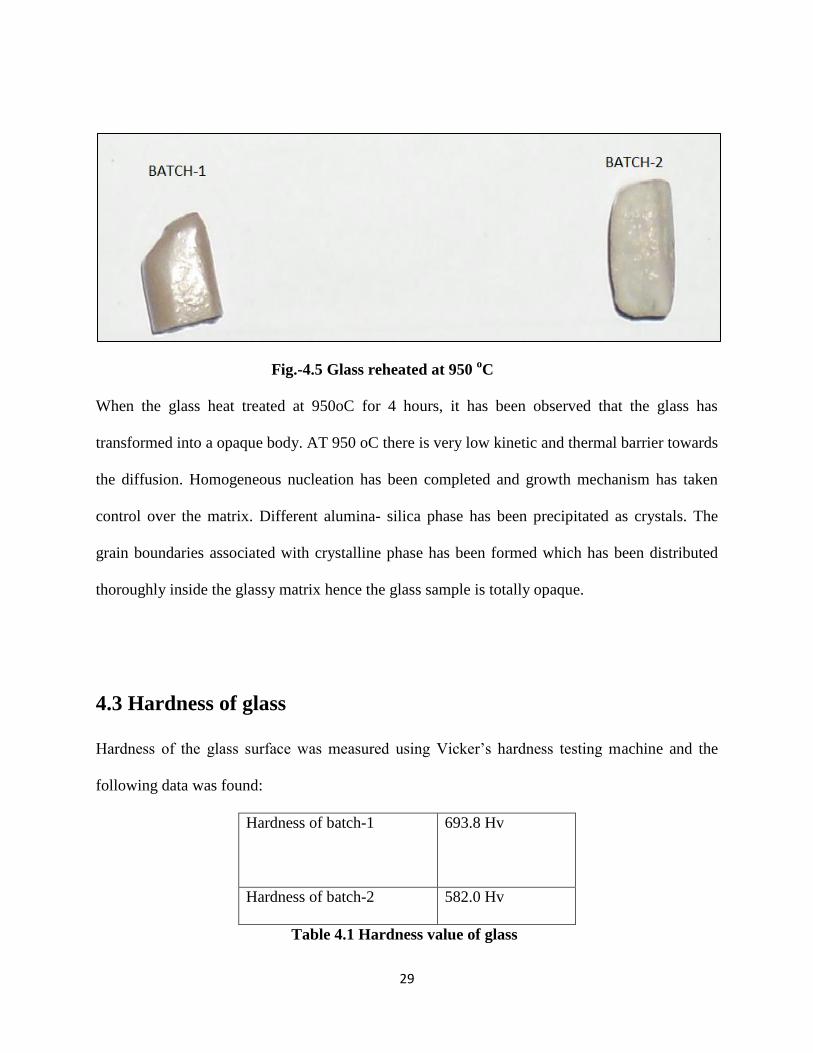
Fig.-4.5 Glass reheated at 950 oC
When the glass heat treated at 950oC for 4 hours, it has been observed that the glass has
transformed into a opaque body. AT 950 oC there is very low kinetic and thermal barrier towards
the diffusion. Homogeneous nucleation has been completed and growth mechanism has taken
control over the matrix. Different alumina- silica phase has been precipitated as crystals. The
grain boundaries associated with crystalline phase has been formed which has been distributed
thoroughly inside the glassy matrix hence the glass sample is totally opaque.
4.3 Hardness of glass
Hardness of the glass surface was measured using Vicker’s hardness testing machine and the
following data was found:
Hardness of batch-1
693.8 Hv
Hardness of batch-2 582.0 Hv
Table 4.1 Hardness value of glass

30
It can be seen that batch 1, which is having a higher amount of TiO2, has a higher strength. Thus
the effect of nucleating agent can be seen. The increased nucleation, strengthens the structure
and increases hardness. As there is more number of nucleating site available therefore, it lead to
more crystallization. As the crystallization has been extended to surface therefore, it can be
summarized that alumina reach phase has been precipitated throughout the matrix. Alumina
silica phase offers high hardness. Therefore, there is increase in surface hardness value as there
are more crystals site available on the surface. On the other hand, batch 2, having a lower TiO2
content has a lower strength, although the amount of glass former B2O3 is more.
4.4 Bulk density of glass sample
Bulk density was measured by Archimedes principle and the data found:
D(g) S(g) W(g) BD=D/W-S(g/cc)
Batch-1 4.1719 2.692 4.177 2.8142
Batch-2 4.2935 2.765 4.290 2.8154
Table 4.2 bulk density of glass
The data shows that the density almost remains similar in both batches. The change in the
percentage of nucleating agent and glass former, if less than 1%, doesn’t affect the density much.
Batch, although, has a slightly higher density due a higher B2O3 content.

31
4.5 Flexural strength of glass
The flexural strength has been calculated for each batch using the following formula:
M.O.R. = 2
Fig. 4.6 Displacement at breaking point vs max. load
For batch 1, the flexural strength was found to be 101.446 MPa at a maximum extension of
0.3910 mm. For batch 2, the flexural strength was found to be 91.8 MPa at a maximum
extension of 0.2750 mm. A higher amount of nucleating agent TiO2 in batch 1 leads to more
crystallization and thus a higher strength. Also, the brittleness due to the glassy phase is lower
and a greater extension can be seen. As there is more site for nucleation available therefore,
crystallization is more. Crystal phases are embedded in glassy matrix which offer high resistance
32
towards the crack propagation. Therefore, the glass ceramic which have more nucleating agent
have more crystallization shows more flexural strength.
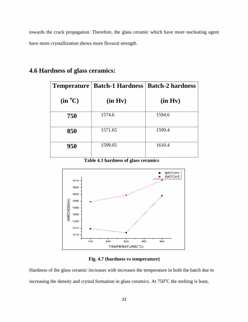
4.6 Hardness of glass ceramics:
Temperature
(in oC)
Batch-1 Hardness
(in Hv)
Batch-2 hardness
(in Hv)
750 1574.6 1594.6
850 1571.65 1599.4
950 1599.05 1610.4
Table 4.3 hardness of glass ceramics
Fig. 4.7 (hardness vs temperature)
Hardness of the glass ceramic increases with increases the temperature in both the batch due to
increasing the density and crystal formation in glass ceramics. At 750oC the melting is least,

33
hence, on cooling the crystallisation is not significant. Since the glass ceramic formation is
minimal, the stregth is lowest in this case. The same happens at 850oC but here the stregth is
higher due to higher crystalline phase formation. At 950oC, the stregth is highest as the
crystalline phase formation is the highest here.
4.7 Bulk density of glass ceramic
As the glass volume is fixed so nucleation and growth which took place inside the glassy matrix
did not offer much towards the bulk density. The glassy matrix is generally consists of alumina
silica. Alumina as well as silica present inside the glassy matrix as 4 coordination state. All Si is
surrounded by 4 oxygen. Same can also be sated for alumina. Alumina is also present in the 4
coordination state. As there is glassy phase therefore, it offers high specific volume than its
corresponding crystalline phase . The high specific volume lead to high free volume inside the
glassy phase. As there is nucleation and growth took place, therefore, these free volumes are
getting occupied by crystallization. As there is no mass transport from outside, all mass transport
are due to diffusion mechanism inside the glassy matrix, therefore there is no increase is mass as
well as there is no increase in volume . Hence there is no significant chance is bulk density.

34
Fig. 4.8 (bulk density VS temperature)
As shown in graph, density increases slightly with increase in temperature, because with increase
in temperature, volume decreases slightly but crystallization in the glass ceramic increases with
temperature filling up the free volume. Since, mass is constant here, therefore density increases
slightly. At 750oC density for batch-1 and batch-2 found 2.797 and 2.832 g/cc respectively. At
850oC density found very similar and at 950oC density for batch-1 and batch-2 found 2.918 and
2.852 g/cc respectively.

35
4.8 Compressive strength of glass ceramics
Fig. 4.9 (CCS vs temperature)
As shown in fig. 4.4 CCS value increases with increase the temperature because crystalline form
increases with increases the temperature. At 750oC the melting is least, hence, on cooling the
crystallisation is not significant. Since the glass ceramic formation is minimal, the stregth is
lowest in this case. The same happens at 850oC but here the stregth is higher due to higher
crystalline phase formation. At 950oC, the stregth is highest as the crystalline phase formation is
the highest here.

36
4.9 Dilatometer test of glass ceramic
Fig. 4.10 (temperature vs dL/Lo)
Thermal expansion co-efficient=8.028×10⁻⁶
/°C in the range of 400oC.So it can be used as
cooktop. As there is high alumina content present in glass ceramic phases therefore it shows very
less thermal expansion coefficient. The alumina in glassy matrix offer high viscosity at low
temperature. So on heating the alumina phases cannot go inside the free volume. As there is also
silica phase present inside the glassy matrix therefore, it offers low thermal expansion
coefficient.

37
4.10 Microstructure observation by FESEM
Fig.4.11 Glass ceramic fired at 850oC Fig.4.12 Glass ceramic fired at 950
oC
From the microstructure it has been observed there are crystal phases embedded inside the glassy
matrix. In sample heat treated at 850oC shows very tiny crystals embedded inside the glassy
matrix. No porosity has been observed in the samples. IN the samples heat treated at 950oC ,
there is some crystal boundary seems to be visible. Similarly no porosity has been observed in
this samples.
CHAPTER:5

38
CONCLUSION

39
5.1 Conclusion
It can be concluded that :
Melting temperature for this composition was found about 1400oC with soaking time
about 1hour.
B F SLAG Al2O3 CaF2 B2O3 TiO2
Batch-1(Wt%) 80 10 5 4 1
Batch-2(Wt%) 80 10 5 4.5 0.5
Hardness of the glass ceramic increases with increases the temperature of heat
treatment in both the batch.
Density increases continuously with increase in temperature of heat treatment in both
the compositions.
CCS value increases with increase the temperature because crystalline form increases
with increases the temperature.
This glass-ceramics shows lower thermal expansion co-efficient. Thermal expansion
co-efficient=8.028×10⁻⁶
/°C in the range of 400oC.So it can be used as cooktop
application.

40
REFERENCE
1. Yan Zhao, Dengfu Chen a, Yanyan Bi, Mujun Long. Preparation of low cost
glass–ceramics from molten blast furnace slag , Ceramics International 38 (2012)
,pp.2495–2500
2. Hongyu Liu, Hongxia Lu , Deliang Chen, Hailong Wang, Hongliang Xu, Rui
Zhang. Preparation and properties of glass–ceramics derived from blast-furnace
slag by a ceramic-sintering process , Ceramics International 35 (2009), pp. 3181–
3184
3. A.A. Francis. Conversion of blast furnace slag into new glass-ceramic material ,
Journal of the European Ceramic Society 24 (2004) pp. 2819–2824
4. I. K. Mihailova1,*, P. R. Djambazki1, D. Mehandjiev2 . The effect of the
composition on the crystallization behavior of sintered glass-ceramics from blast
furnace slag , Bulgarian Chemical Communications, Volume 43, Number 2 2011,
pp. 293–300
5. Bahman Mirhadi, Behzad Mehdikhani . Effect of calcium fluoride on sintering
behaviour of SiO2-CaO-Na2O-MgO glass-ceramic system , Processing and
Application of Ceramics 6 [3] (2012) ,pp.159–164
6. LI Yu1, LIU XiaoMing, SUN HengHu & CANG DaQiang . Mechanism of phase
separation in BFS (blast furnace slag) glass phase, SCIENCE CHINA
Technological Sciences , January 2011 Vol.54 No.1: pp.105–109

41
7. G. A. Sycheva and I. G. Polyakova . Volume Nucleation of Crystals in Glass
Based on BlastFurnace Slag , ISSN 10876596, Glass Physics and Chemistry,
2013, Vol. 39, No. 3, pp. 248–260
8. G.A. Khater, Influence of Cr2O3, LiF, CaF2 and TiO2 nucleants on the
crystallization behavior and microstructure of glass-ceramics based on blast-
furnace slag, Ceramics International 37 (2011) pp.2193–2199.
9. Zhong-jie Wang, Wen Ni, Yan Jia, Li-ping Zhu, Xiao-yan Huang, Crystallization
behavior of glass ceramics prepared from the mixture of nickel slag, blast furnace
slag and quartz sand, Journal of Non-Crystalline Solids 356 (2010) pp.1554–1558.


![iretrading.comiretrading.com/media/partners/KET Float Valve Overview.pdf · Translate this page%PDF-1.6 %âãÏÓ 6078 0 obj endobj 6097 0 obj /Filter/FlateDecode/ID[]/Index[6078](https://static.fdocuments.net/doc/165x107/5ae72a817f8b9acc268e4354/float-valve-overviewpdftranslate-this-pagepdf-16-6078-0-obj-endobj-6097-0-obj.jpg)


