Development Checklist - City of Cartersville
24
Development Checklist Attached is a guidance document regarding the review and approval of development plans. It is the responsibility of the developer and/or engineer to obtain the most current criteria required for development projects, as development requirements are updated regularly. Relevant documents include the City of Cartersville Development Regulations, Landscaping Ordinance, Sign Ordinance, and Zoning Ordinance. This material is available on the Planning & Development page of the City of Cartersville website, www.cityofcartersville.org, and can also be obtained in hard copy from the Planning & Development department, located on the 2 nd floor of City Hall, 10 North Public Square. If you have any questions, please contact a Planning & Development representative at 770-387-5600.
Transcript of Development Checklist - City of Cartersville

Development Checklist
Attached is a guidance document regarding the review and approval of development plans. It is the responsibility of the developer and/or engineer to obtain the most current criteria required for development projects, as development requirements are updated regularly. Relevant documents include the City of Cartersville Development Regulations, Landscaping Ordinance, Sign Ordinance, and Zoning Ordinance. This material is available on the Planning & Development page of the City of Cartersville website, www.cityofcartersville.org, and can also be obtained in hard copy from the Planning & Development department, located on the 2nd floor of City Hall, 10 North Public Square.
If you have any questions, please contact a Planning & Development representative at 770-387-5600.

City of Cartersville Contact List Planning and Zoning Cartersville Public Works Georgia Power Richard Osborne, 770-387-5614 Wade Wilson, Engineer 41 Massell Dr 10 Public Square 330 South Erwin St. Cartersville, GA 30121 PO Box 1390 PO Box 1390 770-382-1110 Cartersville, GA 30120 Cartersville, GA 30120-1390 Fax 770-387-5605 Phone 770-383-7432 Utilities Protection [email protected] Fax 770-387-5697 1-800-282-7411 [email protected] City Attorney Keith Lovell Landscaping and Signs Cartersville Gas System 336 S. Tennessee St Tim Jones or Richard Osborne Brian Friery, Engineer Cartersville, GA 30120 10 Public Square 4 Cook St. 770-386-1116 PO Box 1390 PO Box 1390 Cartersville, GA 30120-1390 Cartersville, GA 30120 City of Cartersville GIS Phone 770-387-5600 Phone 770-387-5642 Todd Jessee Fax 770-387-5605 Fax 770-387-5638 770-607-1155 [email protected] [email protected] [email protected] Building Inspections Cartersville Water & Sewer System David Dye, Building Official Ed Mullinax, Assistant Director 10 Public Square 148 Walnut Grove Road PO Box 1390 PO Box 1390 Cartersville, GA 30120-1390 Cartersville, GA 30120-1390 Phone 770-387-5671 Phone 770-387-5653 Fax 770-387-5605 Fax 770-606-2386 [email protected] [email protected] Fire Department Bartow County Water & Sewer Mark Hathaway, Fire Marshal Roger Ellis, Assistant Director or Eric Williams 50 Nelson St. 195 Cassville Rd Cartersville, GA 30120 PO Box 1390 Phone 770-387-5170 Cartersville, GA 30120-1390 [email protected] Phone 770-387-5635 Fax 770-387-7413 [email protected] Bartow County Health Department 100 Zena Drive Cartersville Electric System Cartersville, GA 30121 Derek Hampton, Engineering Supervisor 770-387-2614 or Rick Ross 320 S. Erwin St. PO Box 1390 GA Department of Transportation Cartersville, GA 30120 500 Joe Frank Harris Pkwy. SE Phone 770-387-5631 Cartersville, GA 30121 Fax 770-387-5630 Driveways – 770-387-3635 [email protected] Utility Encroachments- 770-387-3614 [email protected]

CITY OF CARTERSVILLE ELECTRIC SYSTEM DEVELOPMENT CHECK LIST
Development: _________________________________________________________ Plan Reviewer: _________________________________ Concept Plan Check List Concept Plan Rec'd: ______________ Concept Meeting: ________________ _____ A1 Existing R/W shown, both sides, to nearest intersecting street _____ A2 Existing easements shown on-site and adjacent to site _____ A3 Existing P/L shown on-site and adjacent to site _____ A4 Existing utility equipment shown on-site and adjacent to site _____ A5 Existing OH/UG utility lines shown on-site, off-site, and adjacent to site _____ A6 Other items as noted _____ A7 Review OH/UG utility requirements _____ A8 Review adequacy of primary lines _____ A9 Review future development of adjacent properties _____ A10 Review territorial service rights _____ A11 Discuss utility design in general _____ A12 Discuss outdoor lighting in general _____ A13 Discuss easements in general _____ A14 Discuss service, lighting, traffic signal, and/or construction fees in general _____ A15 Written comments submitted Construction Plan Check List Constr. Plan Rec'd: __________ Revision Meeting: ___________ _____ B1 Items A1-A6 above Revised Plan Rec'd: _____ B2 Proposed R/W Approval Meeting: _____ B3 Proposed utility easements _____ B4 Proposed P/L _____ B5 Proposed utility equipment _____ B6 Proposed utility lines _____ B7 Proposed pump station locations _____ B8 Proposed street lighting locations _____ B9 Proposed traffic signal locations _____ B10 Proposed amenity, irrigation, service, maintenance locations _____ B11 Utility conflicts addressed _____ B12 Road crossing conflicts addressed _____ B13 Depth profile of existing underground utilities shown _____ B14 Load Information Rec'd - Avg. unit size, HVAC, gas/electric heat, appliances _____ B15 Other items as noted _____ B16 Other items as noted

_____ B17 Completed revenue/cost ratio for construction _____ B18 Completed revenue/cost ratio for lighting _____ B19 Submitted required easements for execution _____ B20 Submitted required service fees for payment _____ B21 Submitted required outdoor lighting fees for payment _____ B22 Submitted required traffic signal fees for payment _____ B23 Submitted required contribution to construction fees for payment _____ B24 Submitted required outdoor lighting contract for execution _____ B25 Building permit approved and signed _____ B26 Preconstruction Meeting held (if req'd) _____ B27 Construction Plans approved and stamped Final Plat Check List Final Plat Received: __________ Final Plat Approved: __________ _____ C1 Service fees paid _____ C2 Outdoor lighting fees paid _____ C3 Traffic signal fees paid _____ C4 Contribution to construction fees paid _____ C5 Outdoor lighting contract executed and received _____ C6 Required easements executed and received _____ C7 Existing and required utility easements shown _____ C8 Conflicts involving location of utility lines/equipment resolved _____ C9 Conflicts involving location of road crossings resolved _____ C10 Permanent property pins installed _____ C11 Final plat approved and signed Power will not be connected until all applicable sections of this checklist are completed.

REQUEST FOR SERVICE CARTERSVILLE ELECTRIC SYSTEM CES3011
Customer Name: ____________________________________ Phone #:____________________
Service Address: _________________________________________ Date: _________________ _________________________________________________
Account Number (if existing customer): _____________________________________________ Electrical Contractor: ____________________________ General Contractor: ___________________________ Property Owner: ________________________________ Electrical Engineer: ___________________________ DESIRED SERVICE CHARACTERISTICS: Method of Service Wanted? OVERHEAD UNDERGROUND
Service Voltage Wanted? circle needed voltage 120VAC 120/240VAC 120/208VAC 277/480VAC SINGLE PHASE OR THREE PHASE Service Size Wanted? ______ Wires Size to be Used for Service Entrance Conductors?_____________________ Date Temporary Service Will Be Needed? __________ Date Permanent Service Will Be Needed? ____________ Are Any of the Following Needed? Fault Currents or Motor Starting Increments or Confirmation of Service Send this information to: enter name / address / email / phone #________________________________________ STRUCTURE INFORMATION: Is this a Business or Residence? ______________________________ Type of Structure? ________________________________ Total Square Feet? _____________ Square Feet Heated/Cooled? _______________ Square Feet Warehouse or Garage? __________
LOAD INFORMATION: Will Gas be Used? YES / NO What Appliances? (circle all that apply) STOVE OVEN WATER HEAT HEATING ETC
ENTER LOAD in kW, Tons or HP ONLY, DO NOT ENTER AMPS DESCRIPTION 1 PHASE 3 PHASE Interior Lights Exterior Lights Air Conditioning (heatpump or regular A/C) # of Units =______ Size of Unit #1 Size of Unit #2 Size of Unit #3 Heating (heat strips either for heatpump or electric Heat) ) # of Units =______ Size of Unit #1 Size of Unit #2 Size of Unit #3 Air Handling Equipment # of Units =______ Cooking Equipment # of Units =______ Water Heating # of Units =______ Refrigeration # of Units =______ Receptacles

Motors # of Units =______ Misc. Power Largest Single Motor That Will Be Connected to This Service
CES USE ONLY Contract Required?____________________ Contract Executed?_____________________
DEMANDS (kW) Existing Additional or Total Anticipated in Future
SUMMER WINTER
Added Revenue:____________ Rate:____________ kW Minimum:____________ Annual kWh:___________ METERING INFO: Meter Location: Pedestal / Building / Pole / Other ________________________________________________ Meter Form to Be Used:_________ CT Quantity/Size/Type/Mounting/Arrangement:______________________

Plan Requirements for Cartersville Fire Department
(1) Fire hydrants are to be not more than 500ft. apart with additional hydrants located as necessary to permit all portions of buildings to be reached by hose lays of not more than 300 feet in length. All fire hydrants should be shown on all plans in accordance with Cartersville Development Regulations section 5.3.3. Heavy Industrial zoning requires 300 ft. separation.
(2) All new fire hydrants shall be flow tested in accordance with approved practices of I.S.O, AWWA, and the N.F.P.A to determine the GPM flow for that hydrant. Hydrants will then be color coded in the following fashion in accordance with N.F.P.A 291 and Cartersville ordinance 9-34 Fire Hydrant Testing, Maintenance and Identification:
a) Barrels: Safety Yellow b) Bonnets and Caps: GPM flow 0 to 499- Safety Red*
GPM flow 500 to 999- Safety Orange* GPM flow1000 to 1499- Safety Green* GPM flow 1500 +- Safety Blue*
* Color coding is only descriptive of the GPM flow at the time of the last documented test.
c) Trim of bonnet: Silver or White Reflective d) Out of service hydrants shall be solid yellow with no reflective stripe until placed
in service or removed. e) All Private hydrants are to be painted solid red, barrels, bonnets, and caps
(3) Buildings needing sprinkler systems per Sec.9-29 must have a fire hydrant within 50 ft. of the sprinkler vault and FDC. The vault, FDC, PIV, and the hydrant must be shown on plans. PIV’s must be electronically supervised and padlocked.
(4) Separate sprinkler and fire alarm plans, if required, must also be submitted for approval. (5) Fire Department connections shall be located a minimum of 50 ft. or 1 ½ times the height
of the structure, whichever is greater, from the building. (6) In addition to a hard copy, a copy of all CAD files on buildings and subdivisions in
DWG, DXF, or CZD format shall be provided. Micro station and AutoCAD have specialized entities that cannot be read into other programs. Within these programs, if the drawing is exploded three times all should be removed. Most, if not all of the drawing, will be read into our FHSketch CAD program. If we could get a floor and plot plan, we can add the other information to our pre-fire plans. Any information that you have will be appreciated. All files should be emailed to [email protected] or brought on disc, flash drive, or other form of portable media storage device.
(7) Engineers should follow the latest code editions as adopted by the Georgia Department of Community Affairs O.C.G.A 8-2-20(9)(B). Currently this is 2012 International Fire Code, 2012 NFPA 101 Life Safety Code, and 2010 Edition of ADA, all with State Fire Marshal revisions per the state minimum fire code O.C.G.A 120-3-3.
a) All life safety items should be shown on building plans… example; fire extinguishers, emergency lights, exit signs.
b) Alarm information, if alarm system is required, should be shown on plans. c) Any state fire marshal approved plans must also be submitted to CFD for review
after stamped for approval by the state fire marshal office. (8) A stamped copy of all applicable plans (site, building, sprinkler, fire alarm, etc.) must be
kept on job site at all times. (9) Any new building or renovation over 50% will be required to purchase a Knox Box per
Sec.9-31. This is an emergency key box that is mounted to the building between 6 and 12 feet from the ground. We are not responsible for mounting the box, you are. Order forms can be picked up at Fire Station 1.
(10)A minimum 20 foot fire lane in accordance with IFC Appendix Dshould be maintained around all buildings.
Cartersville Fire Department Site Plan Requirements
Items to be included on cover page
1. Project Name ( ) 2. Project Address ( ) 3. Drawing Legend ( ) 4. Compass North ( ) 5. Site location map ( ) 6. 24 hour contact name and number ( ) 7. Owner Name and address ( ) 8. Architect name, firm, signed and dated stamp ( ) 9. Other project contacts ( ) 10. Scale (if relevant) ( ) 11. Any related notes ( )
Items to be shown on site plan Utility Page
1. Fire hydrant water line size ( ) 2. Two (2) closest fire hydrants and distance to building ( ) 3. Fire Sprinkler vault, FDC, and PIV location ( ) 4. Fire sprinkler water main size ( ) 5. Fire Department access roads ( ) 6. Road names ( ) 7. Building footprint ( ) 8. Scale ( ) 9. Any related notes ( )

Cartersville Fire Department Building Plan Requirements
Items to be included on cover sheet 1. Project Name ( ) 2. Project Address ( ) 3. Drawing Legend and abbreviations ( ) 4. Compass North ( ) 5. Site location map ( ) 6. 24 hour contact name and number ( ) 7. Architect name, firm, signed and dated stamp ( ) 8. Other project contacts ( ) 9. Building Summary block ( )
a. Project name ( ) b. Location ( ) c. Owner contact ( ) d. Occupancy Classification ( ) e. Building Area ( ) f. Occupancy Load w/ calculations ( ) g. Fire Protection ( ) h. Construction Type ( )
10. Code set block ( ) 11. Drawing Index ( ) 12. General Notes ( ) 13. Scale ( )
Items to be included in Floor Plan
1. Life Safety plan* ( ) 2. Above or below ground tank locations* ( ) 3. Floor plan to scale ( ) 4. Emergency lighting* ( ) 5. Exit signage* ( ) 6. Fire Extinguisher locations and height AFF* ( ) 7. Knox Box location and height AFF ( ) 8. Grease hood detail w/man. pull locations and height AFF* ( ) 9. Emergency generator details* ( ) 10. ADA details* ( ) 11. Fire wall detail w/U.L listing number* ( ) 12. Fire sprinkler riser location ( )
*May be on floor plan or separate page as long as these items are included in the plan set
Contact Information: Fire Marshal Mark Hathaway 770-387-5636 [email protected] Capt. Eric Williams 770-387-5636 [email protected] Lt. Mike Taylor 770-387-5636 [email protected]

CARTERSVILLE GAS SYSTEM PLAN REVIEW CHECK LIST As necessary, plan review meetings with the Gas System will be available Mondays & Wednesdays at 2:00 PM, 2:30 PM, 3:00 PM & 3:30 PM provided an appointment is made the prior Thursday before 4:30 PM for Monday meetings and the prior Monday before 4:30 PM for Wednesday meetings. Appointments may be scheduled by calling the Gas System Offices at 770.387.5642. Please state project name and intention of meeting when scheduling. Meetings will be held at Gas System Offices located at 4 Cook St. Section to be completed by Developer NAME OF PROJECT/DEVELOPMENT: _________________________________________ LOCATION: _______________________________________________________________ CONCEPT MEETING DATE (If applicable): ______________________________________ DEVELOPER ENGINEER/CONSULTANT COMPANY: ___________________________ COMPANY: ___________________________ ADDRESS: ___________________________ ADDRESS: ___________________________ C, S, Z: ___________________________ C, S, Z: ___________________________ CONTACT: ___________________________ CONTACT: ___________________________ PHONE(S): (O) ___________ (M) __________ PHONE(S): (O) ___________ (M) ___________ EMAIL: ___________________________ EMAIL: ___________________________ PRELIMINARY PLAT: REVIEWABLE _____ Yes _____ No If “no”, explain: ___________________________________ INITIAL PLAT RECEIPT DATE: _____ COMMENT DATE: _____ COMMENT BY: _____________ RE-REVIEW (As necessary): PLAT RECEIPT DATE: _____ COMMENT DATE: _____ COMMENT BY: __________ PLAT APPROVAL DATE BY GAS SYSTEM: _________________________________________ In accordance with Section 7.5-31 of the City of Cartersville Development Regulations, “preliminary plats” will be reviewed by the City of Cartersville Gas System and shall include the following minimum information. Additional information not included in the following list may be requested by the City of Cartersville and by including such information in no way constitutes an approval. O.K. REVISE N/A __ __ __ Show all under ground existing natural gas facilities within and bordered by property Comment: __________________________________________________________ __ __ __ Show all above ground existing natural gas facilities within and bordered by property Comment: __ __ __ Show all existing natural gas easements within and bordered by property Comment:

CONSTRUCTION PLAN: REVIEWABLE _____ Yes _____ No If “no”, explain: __________________________________ INITIAL PLAN RECEIPT DATE: ______ COMMENT DATE: ______ COMMENT BY: ___________ RE-REVIEW (As necessary): PLAN RECEIPT DATE: ______ COMMENT DATE: ______ COMMENT BY: ___________ PLAN APPROVAL DATE BY GAS SYSTEM: _________________________ In accordance with Section 7.5-31 of the City of Cartersville Development Regulations, “construction plans” will be reviewed by the City of Cartersville Gas System and shall include the following minimum information. Additional information not included in the following list may be requested by the City of Cartersville and by including such information in no way constitutes an approval. O.K. REVISE N/A __ __ __ Requirements of “preliminary plat” Comment:_________________________________________________ __ __ __ Clearly show the proposed work and differentiate from existing features Comment: ________________________________________________ __ __ __ Indicate depth of all existing natural gas facilities within the proposed construction limits Comment: ________________________________________________ __ __ __ Show location and elevation of all existing natural gas facilities on all required profiles Comment: ________________________________________________ __ __ __ Show locations of all proposed natural gas facilities in accordance with Section 7.5- 65(12) of the City of Cartersville Development Regulations Comment: ________________________________________________ __ __ __ Show locations of all proposed utilities in accordance with Section 7.5-65(12) of the City of Cartersville Development Regulations Comment: ________________________________________________ __ __ __ Show and provide all necessary or required natural gas easements Comment: ________________________________________________ __ __ __ Provide any required natural gas Relocation Agreements fully executed by the Developer Comment: ________________________________________________

CONSTRUCTION PLAN (continued): __ __ __ Provide the following notes on the utility sheet if the project involves the installation or relocation of any natural gas facilities EROSION & SEDIMENT CONTROL-NATURAL GAS FACILITY INSTALLATIONS 1. The City of Cartersville Gas System will or cause to provide and apply straw or hay mulch to a depth of 6" over all areas disturbed specifically by the construction of the natural gas facilities within the Development provided no further disturbance of such areas are planned within 14 days of initial disturbance. 2. The Developer will or cause to maintain or re-apply such erosion and sediment control measures as necessary or required to comply with all local, State and Federal erosion and sediment control requirements after initial application as required by #1 above. 3. The Developer will or cause to provide, install, maintain and remove any and all erosion and sediment control measures necessary or required to comply with all local, State and Federal erosion and sediment control requirements which may be associated with the construction of the natural gas facilities within the Development other than #1 above. Comment: _________________________________________________________ __ __ __ Other: Comment: _________________________________________________________ FINAL PLAT: REVIEWABLE _____ Yes _____ No If “no”, explain: ___________________________________ INITIAL PLAN RECEIPT DATE: _____ COMMENT DATE: _____ COMMENT BY: _________ RE-REVIEW (As necessary): PLAT RECEIPT DATE: ______ COMMENT DATE: ______ COMMENT BY: ____________ PLAT APPROVAL DATE BY GAS SYSTEM: _____________________________________ In accordance with Section 7.5-31 of the City of Cartersville Development Regulations, “final plats” will be reviewed by the City of Cartersville Gas System and shall include the following minimum information. Additional information not included in the following list may be requested by the City of Cartersville and by including such information in no way constitutes an approval. O.K. REVISE N/A __ __ __ Completion of the construction of all proposed natural gas facilities Comment: ________________________________________________________ __ __ __ Show all natural gas easements with dimensions, distances and bearings Comment: ________________________________________________________ __ __ __ Other: Comment: _________________________________________________________

Cartersville Planning &
Development
Commercial / Industrial
Plan Review Check List
Name of Project: Location: Zone: Date:
Zoning: note district of subject tract on site plan. Note intended use. Land disturbance permit required for 1.1 acres or more disturbed.
COMMENTS:
If applicable, note on site plan if property is located in Historic District or Overlay District. If property is in Historic District, new construction, demolition, and/or exterior changes require Certificate of Preservation. Overlay District requirements, Zoning Ordinance sections 13.1-12, 14.1-9
COMMENTS:
If applicable, note if property was rezoned or received a variance or special use permit. Note case number(s) and conditions.
COMMENTS:
Exterior finish: refer to applicable Zoning Ordinance district standards. Sprinkling required for 5000 sqft. Sprinkling for alcohol @ 100 seats
COMMENTS:
Note owners and adjoining zoning districts of surrounding properties (including across the street) on site plan.
COMMENTS:
Buffers: if applicable based on Zoning Ordinance district standards, note and show on site plan. Buffer standards in Zoning Ordinance Section 4.17
COMMENTS:
Note Development Standards for zoning district of tract on site plan - Height: Front: Side: Rear: Lot street frontage: Lot width at building line:
COMMENTS:
Parking: note on site plan minimum number of spaces required and number of spaces provided (per use). Zoning Ordinance Section 17.1-6
COMMENTS:
Outdoor Lighting. Note on site plan and adhere to the following: Parking lot outdoor lighting shall have a maximum height of forty-five (45) feet and shall be directed away and shielded from abutting residential districts. Zoning Ordinance Section 4.21 (different if in an Overlay district)
COMMENTS:

Outdoor Storage only allowed in G-C, L-I, and H-I districts. If in G-C or L-I, note on site plan and adhere to following: Outdoor Storage must be located in a side or rear yard and screened from all RW and residential districts that abut outdoor storage area. Zoning Ordinance Section 4.25
COMMENTS:
Waste Dumpster: show location on site plan. Note and adhere to the following: Solid Waste Containers shall be screened from all streets and adjoining properties with a solid, opaque fence or wall which shall be at least six (6) inches taller than the container. Zoning Ordinance Section 4.9
COMMENTS:
Sidewalk. Show all sidewalks required (minimum 5 feet in width, required along frontage on all existing streets, required on at least one side of all new streets). Development Regulations section 7.5-65(10)
COMMENTS:
Landscaping: Civil plans must show landscaping based on Landscaping Ordinance. A separate landscape sheet must be included. Section 17-68
COMMENTS:
Note and show the following: Parking Landscape islands in parking lot required every 12 spaces, and at the end of each single and double row. 320 sqft area double rows & 2 small trees or 1 large tree from tree list. Sod or mulch to be used in islands. 160 sqft area single rows and 1 small tree from tree list. Landscaping Ordinance sections 17-66, 17-73, 17-74
COMMENTS:
Note and show the following: Building perimeter 5 ft landscape strip or sidewalk required. Sod or mulch in landscape strip. Section 17-66
COMMENTS:
Note and show the following: Border landscaping 10 ft wide landscape strip at RW and 5 ft wide along any vehicular use (edge of parking / paving area). Sod grass required. Section 17-66
COMMENTS:
Note and adhere to the following: Tree requirements 8 ft in height at planting, maturation height of at least 15 ft Section 17-65
COMMENTS:
Note and show the following: One tree for every 30 ft in landscape strip at RW. Large trees from tree list shall be planted, no more than 35% of one species of tree shall be used. 2 trees minimum. Section 17-66
COMMENTS:
Note and show the following: One tree for every 75 Ft. of border area. Small trees from tree list shall be planted, no more than 35% of one species of tree shall be used. Section 17-66
Cartersville Planning &
Development
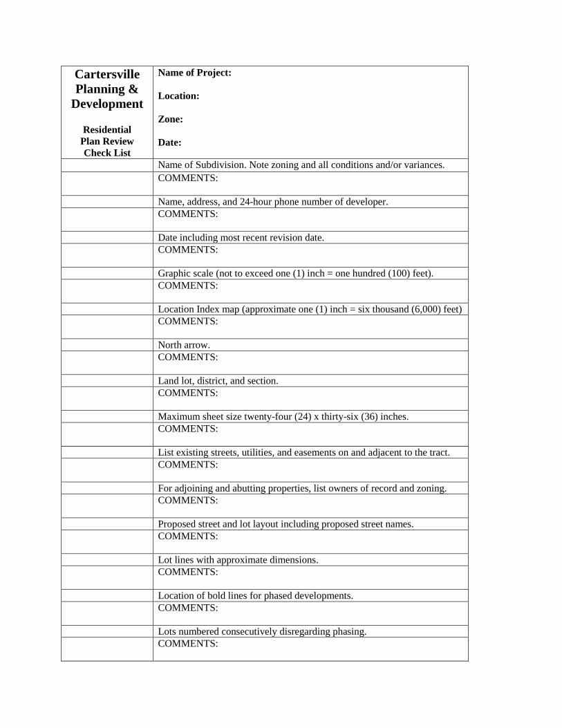
Residential Plan Review Check List
Name of Project: Location: Zone: Date:
Name of Subdivision. Note zoning and all conditions and/or variances. COMMENTS:
Name, address, and 24-hour phone number of developer. COMMENTS:
Date including most recent revision date. COMMENTS:
Graphic scale (not to exceed one (1) inch = one hundred (100) feet). COMMENTS:
Location Index map (approximate one (1) inch = six thousand (6,000) feet) COMMENTS:
North arrow. COMMENTS:
Land lot, district, and section. COMMENTS:
Maximum sheet size twenty-four (24) x thirty-six (36) inches. COMMENTS:
List existing streets, utilities, and easements on and adjacent to the tract. COMMENTS:
For adjoining and abutting properties, list owners of record and zoning. COMMENTS:
Proposed street and lot layout including proposed street names. COMMENTS:
Lot lines with approximate dimensions. COMMENTS:
Location of bold lines for phased developments. COMMENTS:
Lots numbered consecutively disregarding phasing. COMMENTS:

Provisions for water supply, sewerage, and drainage. COMMENTS:
Exact boundary lines of the entire tract indicated by a heavy line giving
lengths and bearings.
COMMENTS:
List total project acreage, total number of lots and lot density, minimum size of lots, minimum lot width and frontage, and required setbacks.
COMMENTS:
Location of 100-year floodplain or statement that no part of the property lies within the 100-year floodplain.
COMMENTS:
Minimum building front yard setback line shown graphically on the plat. COMMENTS:
Surveyor’s and/or Engineer’s stamp. COMMENTS:
Signature statement for planning commission if preliminary plat.
Development Regulations section 7.5-31(2). COMMENTS:
Show all sidewalks required (minimum 5 feet in width, required along
frontage on all existing streets, required on at least one side of all new streets for residential). Development Regulations section 7.5-65(10)
COMMENTS:
Other Items or Comments:

City of Cartersville Commercial Site Plan Check List Public Works Department
Project Name: . Designer: . Checked By: _____________________________. Date: .
Check list marks to be interpreted as follows: √ O.K. X Revision Required N/A Not Applicable
? Additional Information Required All Plans must include: 1. Ground elevations on the tract based on field surveys or
photogrammetric methods from aerial photographs. The basis for the topographic information shall be shown. Contours shall be shown at intervals of two (2) feet, and shall be mean sea level contours.
2. Proposed grading if different than existing contours.
3. Location of 100-year floodplain or statement that no part of property lies within the 100-year floodplain. Any encroachments into areas of Special Flood Hazard will require a floodplain management/flood damage prevention plan for approval (A checklist will be provided in such cases.)
4. Abutting existing City or County Roads showing existing right-of-way and pavement widths.
5. Existing easements, city and county lines, utility lines, bridges, street culverts, etc.
6. Total Acreage of the site.
7. Total impervious surface in square feet.
8. Surveyor’s and Engineer’s stamp.
9. Acceleration/deceleration lanes at entrance.
10. Dimensions of turn radii.

11. Additional right-of-way if required to bring the City Road up to minimum standards.
12. Detail for paving on right-of-way.
13. Curb and Gutter detail.
14. Location, size, and length of existing drainage structures with drainage area.
15. Location, size, length, and type of all proposed drainage structures.
16. Drainage area to each inlet point of the drainage system.
17. Hydrology study by a registered professional engineer.
18. The current Erosion, Sedimentation & Pollution Control Plan Checklist as required by Georgia EPD shall be filled out and submitted with plans.
19. All proprietary devices must have manufacturer's and engineers design, specifications, and installation requirements included in both the Hydrology Study and the Plans.
20. All drainage structure outlets to be erosion proofed.
21. Proposed off-street parking facilities to be paved. Include dimensions of parking lot, parking spaces, and maneuvering aisles.
22. Proposed finished floor elevation of building(s).
23. Centerline and width of nearest existing street/driveway if within one (100) feet of proposed entrance centerline.
24. Location and mean sea level elevation of bench mark.
25. Sidewalks. (Required on at least one side of the street on all new developments and are required on existing streets where new development occurs.)
26. Dumpster Location.

27. Hydrology Study To include the following items and calculations. a. Hydrology study should bear a stamp of a registered engineer or
landscape architect registered in the State of Georgia.
b. Name of the project and its location.
c. Description of current and proposed uses and conditions.
d. Description of downstream (upstream as well if necessary) conditions and assessment of downstream capacities. Discuss how method of runoff control will not adversely affect downstream property.
e. Method used in analysis.
f. The development shown on a USGS quad topography map.
g. An existing conditions map of the project with topography and soils shown, drainage basins delineated (including intermittent or perennial streams, wetlands, floodplain boundaries and other surface water features), acreages shown and Curve Numbers included. Off site drainage information should be shown.
h. A proposed conditions map of the project with proposed topography shown, wetlands, streams or water features and, drainage basins delineated, acreages shown and Curve Numbers included. Appropriate buffers(appropriate to warm or cold/trout streams) and additional 25' setback beyond buffers where impervious surfaces are prohibited to be shown. All stormwater management elements to be shown along with any by-pass shown and quantified. Offsite drainage information should also be included. Any encroachments into stream buffers or setback will require special approval (A checklist will be provided in such cases.).
i. Time of concentration for each basin shown.
j. Curve Numbers for existing and proposed conditions. Include calculations.
k. Peak flows for all storm return events for existing and proposed conditions, pond by-pass, and allowable detention pond release rates.
l. Water Quality Volume Calculations (WQv) and Water Quality Site Development Review Tool from the GSMM (Blue Book).
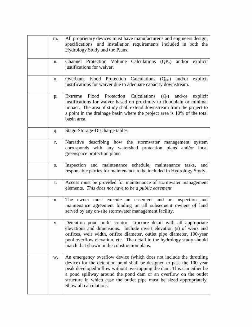
m. All proprietary devices must have manufacturer's and engineers design,
specifications, and installation requirements included in both the Hydrology Study and the Plans.
n. Channel Protection Volume Calculations (QPv) and/or explicit justifications for waiver.
o. Overbank Flood Protection Calculations (Qp25) and/or explicit justifications for waiver due to adequate capacity downstream.
p. Extreme Flood Protection Calculations (Qf) and/or explicit justifications for waiver based on proximity to floodplain or minimal impact. The area of study shall extend downstream from the project to a point in the drainage basin where the project area is 10% of the total basin area.
q. Stage-Storage-Discharge tables.
r. Narrative describing how the stormwater management system corresponds with any watershed protection plans and/or local greenspace protection plans.
s. Inspection and maintenance schedule, maintenance tasks, and responsible parties for maintenance to be included in Hydrology Study.
t. Access must be provided for maintenance of stormwater management elements. This does not have to be a public easement.
u. The owner must execute an easement and an inspection and maintenance agreement binding on all subsequent owners of land served by any on-site stormwater management facility.
v. Detention pond outlet control structure detail with all appropriate elevations and dimensions. Include invert elevation (s) of weirs and orifices, weir width, orifice diameter, outlet pipe diameter, 100-year pool overflow elevation, etc. The detail in the hydrology study should match that shown in the construction plans.
w. An emergency overflow device (which does not include the throttling device) for the detention pond shall be designed to pass the 100-year peak developed inflow without overtopping the dam. This can either be a pond spillway around the pond dam or an overflow on the outlet structure in which case the outlet pipe must be sized appropriately. Show all calculations.

x. Pond routing print-outs for each storm event.
y. Summary table comparing routed flows with allowable release rate
flows for each storm event.
z. All stormwater management elements (pond, proprietary device, infiltration trench, etc.) should be clearly illustrated on the plans with topographic information, flow arrows, 100-year pool limits shown and elevation called out. The outlet structure location and any associated piping should be clearly illustrated. No utilities should run through the stormwater management area.
aa. It should be clear from the overall grading/drainage plan from contours, flow arrows and piping what areas flow to or bypasses the stormwater management elements.
bb. If there are any walls associated with the stormwater management elements, the engineering design should be included in the plans and certified by an engineer registered in the State of Georgia. All information required to build the wall should be included in the plans with the reinforcing bar schedules, illustrated cross-sections and profile of the wall and footing with all necessary dimensions and elevations, etc. Include calculations for factor of safety against overturning and sliding.
cc. A fully illustrated outlet structure detail should be included in the plans which should match that included in the hydrology study.
dd. If the a pond is four feet or deeper, a chain link or privacy fence six feet tall is required.
Additional Comments:

GAR 100001 ES & PC Plan Review Checklist
Project: . Permit Page
Included Y/N
“Y” indicates item is addressed. “N” indicates revisions required.
4 ______ 1. Design professional qualifications.
14 ______ 2. Design professional certification statement and signature that the permittee’s ES&PC Plan provides for an appropriate and comprehensive system of BMPs, and sampling expected to meet permit requirements.
15 ______ 3. Design professional certification that the site was visited prior to
development of the ES&PC Plan.
15 ______ 4. Indication that no activities shall be conducted within the 25 or 50-foot stream buffer along the banks of all state waters.
16 ______ 5. Plan describes practices used to reduce the pollutants in storm
water discharges.
17 ______ 6. Indication that the design professional who prepared the ES&PC Plan is to inspect the installation of BMPs within 7 days after initial construction activity begins.
17-30 ______ 7. Signed by the design professional and includes the certification
in accordance with section V.G.d. of the permit.
18 ______ 8. Indication that amendments to the ES&PC Plan which have a significant effect on BMPs with a hydraulic component must be certified by the design professional.
18-19 ______ 9. Plan contains BMPs that are consistent with and no less
stringent than the Manual for Erosion and Sediment Control in Georgia including initial perimeter controls, intermediate grading and drainage BMPs, and final BMPs. (See checklist on page 2 for other Plan components)
19 ______ 10. Description of the nature of construction activity.
19 ______ 11. Description and chart or timeline of the intended sequence of
major activities.
19 ______ 12. Estimate of the total area of the site and the total area expected

to be disturbed.
19 ______ 13. An estimate of the runoff coefficient or peak discharge flow of the site prior to and after construction activities are completed should be shown.
19 ______ 14. Site map including drainage patterns, surface waters including
wetlands, and locations where storm water is discharged to surface water.
19 ______ 15. Receiving waters and wetland areas identified.
20 ______ 16. Sediment basins or the calculations documenting 67 cubic yards
of storage per acre drained.
20 ______ 17. Rationale explaining the decision not to use sediment basins on the site.
20 ______ 18. Description of the measures that will be installed during the
construction process to control pollutants in storm water that will occur after construction operations have been completed.
21 ______ 19. Indication that waste materials shall not be discharged to waters
of the State, except as authorized by a Section 404 permit.
21 ______ 20. BMPs to minimize off-site vehicle tracking of sediments and the generation of dust.
21 ______ 21. Documentation that the ES&PC Plan is in compliance with
waste disposal, sanitary sewer, or septic tank regulations
21 ______ 22. BMPs for the remediation of all petroleum spills and leaks.
21-24 ______ 23. Details on required inspections and record keeping by the primary permittee, secondary permittees, and tertiary permittees
24 ______ 24. Description of procedures to ensure timely maintenance of
vegetation, erosion and sediment control measures.
24 ______ 25. Perennial and intermittent streams and other water bodies into which storm water is discharged.
24 ______ 26. Sampling locations.
24 ______ 27. Analytical methods used to collect and analyze the samples
from each location.

24 ______ 28. Appendix B Rationale for outfall sampling points.
24 ______ 29. Information on sampling frequency and reporting requirements.
Checklist for Plan Components (No. 12) ______ 1. Graphic scale and north arrow
______ 2. Vicinity map
______ 3. Existing and planned contours
______ 4. Contributing drainage areas delineated with acreage both on and
off site
______ 5. Locations of erosion and sedimentation control features using uniform coding symbols
______ 6. Undisturbed stream buffers adjacent to state waters delineated
______ 7. Soil series delineated
______ 8. Receiving streams delineated and a description of neighboring
areas which might be affected
______ 9. Phased plan into initial, intermediate and final phases
______ 10. ES&PC plan for typical building lot and each situational lot in the development
______ 11. Limits of construction or limits of disturbance shown
______ 12. Revision and/or initial date of plan
______ 13. Name, address and phone number of primary permittee.
______ 14. Name of 24-hour contact person
______ 15. Vegetation plan
______ 16. Detail specifications for all structural BMPs that meet the
standards of the Manual for Erosion and Sediment Control GA