DEVELOPMENT AND VALIDATION OF HIGH …€¦ · of reservoir tanks or main pipes with branches ......
12
- 1 - DEVELOPMENT AND VALIDATION OF HIGH-PRECISION CFD METHOD WITH VOLUME-TRACKING ALGORITHM FOR GAS-LIQUID TWO-PHASE FLOW SIMULATION ON UNSTRUCTURED MESH I1. Kei Ito 1, 2 , I2. Tomoaki Kunugi 1 , I3. Hiroyuki Ohshima 2 1 Department of Nuclear Engineering, Kyoto University, Yoshida, Sakyo-ku, Kyoto-shi, Kyoto,606-8501, Japan Tel:+81-29-267-4141, Fax:+81-29-266-3675, E-mail:[email protected] 2 Advanced Nuclear System Research and Development Directorate, Japan Atomic Energy Agency Abstract In design studies of Japanese sodium-cooled fast reactors, a compact size reactor vessel is expected to be employed for economical advantages. However, such a design makes coolant velocity higher and may result in occurrence of gas entrainment (GE) phenomena. Since the GE is highly non-linear and too difficult to predict its onset condition by theoretical methods, we are developing a high-precision CFD method to evaluate the GE accurately. The CFD method is formulated on unstructured meshes to establish accurate geometric modeling of complicated reactor systems. As for two-phase flow simulations, a high-precision volume-of-fluid algorithm was employed and newly formulated on unstructured meshes. In the formulation process, a volume-conservative algorithm and a new formulation establishing the mechanical balance between pressure and surface tension were introduced. The developed CFD method was verified by solving well-known driven-cavity and Zalesak’s slotted- disk rotation problems to show the simulation accuracy. Then, we simulated a rising bubble in liquid under Bhaga et al’s experimental conditions. As a result, the developed method showed good agreement with the experiment. Finally, the developed method was validated by simulating the GE phenomena in the basic experiment. The developed method succeeded in reproducing the occurrence of the GE under the experimental GE condition. 1. INTRODUCTION Fast breeder reactors (FBRs) are located as one of the possible energy source in the future, with the object of not only effective use of resources but also environmental conservation. In Japan, a sodium- cooled fast reactor (JSFR) was selected as a possible option due to its high competitiveness in power costs (Ichimiya, 2003) and the fast reactor cycle technology development (FaCT) project has been conducted by JAEA and related organizations. As an important part of the FaCT project, more compact reactor vessel have been studied to enhance the economical competitiveness of the JSFR (Kimura, 2005). However, such a design concept may result in occurrence of cover gas entrainment (GE) from free surface because coolant velocity in the primary system becomes larger and the larger coolant velocity can induce free surface fluctuation in upper plenum region of the reactor vessel. Since bubbles entrained to the coolant due to the GE might cause power disturbance when they go through the reactor core, the GE must be prevented from occurring in the JSFR for a stable operation. The GE phenomena have been studied experimentally and theoretically in many years (Maier, 1998). In those studies, onset conditions of the GE were investigated using experimental systems consisting of reservoir tanks or main pipes with branches (suction pipes). From the experimental results, the correlation of the onset condition was formed as an equation of Froude number (Fr) and branch diameter (Zuber, 1980) and the equation is widely accepted among the researchers. However, some experimental results disagreeing with the equation were reported for the vortical type GE (Daggett, 1974) because effects of Reynolds or Weber numbers become significant in the vortical type GE. Also in GE studies for the FBR systems, experimental results showed that the onset condition of the vortical type GE was dominated by the liquid velocity itself, not the Fr number (Eguchi, 1984). Therefore, it can be expected that the vortical type GE needs special treatment to predict its onset condition. In such cases, full-scale experiments can be a reliable way to evaluate the onset condition
Transcript of DEVELOPMENT AND VALIDATION OF HIGH …€¦ · of reservoir tanks or main pipes with branches ......

- 1 -
DEVELOPMENT AND VALIDATION OF HIGH-PRECISION CFD METHOD WITH
VOLUME-TRACKING ALGORITHM FOR GAS-LIQUID TWO-PHASE FLOW
SIMULATION ON UNSTRUCTURED MESH
I1. Kei Ito 1, 2, I2. Tomoaki Kunugi
1, I3. Hiroyuki Ohshima
2
1 Department of Nuclear Engineering, Kyoto University,
Yoshida, Sakyo-ku, Kyoto-shi, Kyoto,606-8501, Japan
Tel:+81-29-267-4141, Fax:+81-29-266-3675, E-mail:[email protected] 2 Advanced Nuclear System Research and Development Directorate, Japan Atomic Energy Agency
Abstract
In design studies of Japanese sodium-cooled fast reactors, a compact size reactor vessel is expected to
be employed for economical advantages. However, such a design makes coolant velocity higher and
may result in occurrence of gas entrainment (GE) phenomena. Since the GE is highly non-linear and
too difficult to predict its onset condition by theoretical methods, we are developing a high-precision
CFD method to evaluate the GE accurately. The CFD method is formulated on unstructured meshes
to establish accurate geometric modeling of complicated reactor systems. As for two-phase flow
simulations, a high-precision volume-of-fluid algorithm was employed and newly formulated on
unstructured meshes. In the formulation process, a volume-conservative algorithm and a new
formulation establishing the mechanical balance between pressure and surface tension were introduced.
The developed CFD method was verified by solving well-known driven-cavity and Zalesak’s slotted-
disk rotation problems to show the simulation accuracy. Then, we simulated a rising bubble in liquid
under Bhaga et al’s experimental conditions. As a result, the developed method showed good
agreement with the experiment. Finally, the developed method was validated by simulating the GE
phenomena in the basic experiment. The developed method succeeded in reproducing the occurrence
of the GE under the experimental GE condition.
1. INTRODUCTION
Fast breeder reactors (FBRs) are located as one of the possible energy source in the future, with the
object of not only effective use of resources but also environmental conservation. In Japan, a sodium-
cooled fast reactor (JSFR) was selected as a possible option due to its high competitiveness in power
costs (Ichimiya, 2003) and the fast reactor cycle technology development (FaCT) project has been
conducted by JAEA and related organizations. As an important part of the FaCT project, more
compact reactor vessel have been studied to enhance the economical competitiveness of the JSFR
(Kimura, 2005). However, such a design concept may result in occurrence of cover gas entrainment
(GE) from free surface because coolant velocity in the primary system becomes larger and the larger
coolant velocity can induce free surface fluctuation in upper plenum region of the reactor vessel.
Since bubbles entrained to the coolant due to the GE might cause power disturbance when they go
through the reactor core, the GE must be prevented from occurring in the JSFR for a stable operation.
The GE phenomena have been studied experimentally and theoretically in many years (Maier, 1998).
In those studies, onset conditions of the GE were investigated using experimental systems consisting
of reservoir tanks or main pipes with branches (suction pipes). From the experimental results, the
correlation of the onset condition was formed as an equation of Froude number (Fr) and branch
diameter (Zuber, 1980) and the equation is widely accepted among the researchers. However, some
experimental results disagreeing with the equation were reported for the vortical type GE (Daggett,
1974) because effects of Reynolds or Weber numbers become significant in the vortical type GE.
Also in GE studies for the FBR systems, experimental results showed that the onset condition of the
vortical type GE was dominated by the liquid velocity itself, not the Fr number (Eguchi, 1984).
Therefore, it can be expected that the vortical type GE needs special treatment to predict its onset
condition. In such cases, full-scale experiments can be a reliable way to evaluate the onset condition

- 2 -
of the GE in each system. However, considering very high costs and difficulties in measurements,
full-scale experiments may not be the best way to evaluate the GE. Recently, numerical simulations
can be considered to be promising ways as substitutions of the full-scale experiments owing to the
progress of computer systems and numerical methods.
In this paper, we develop and validate a high-precision CFD method to evaluate the GE phenomena
accurately. The CFD method is formulated on unstructured meshes to establish accurate geometric
modeling of complicated reactor systems and to simulate complicated flow pattern accurately in the
reactor systems. As a two-phase flow simulation method, a volume-tracking algorithm based on a
high-precision volume-of-fluid, namely PLIC (Piecewise Linear Interface Calculation, Young, 1982),
is employed and newly formulated on unstructured meshes based on the conventional formulations on
structured meshes. The developed CFD method is verified by solving well-known driven-cavity and
Zalesak’s slotted-disk rotation (Zalesak, 1979) problems to show that our CFD method has
comparable or higher simulation accuracy than conventional high-precision methods. We also
formulate a new volume-conservative algorithm establishing perfect volume conservation for each
phase (gas and liquid phases). In addition, new algorithms were introduced to velocity and pressure
calculation procedures of the CFD method. We show that the collocated variable arrangement
employed in our CFD method often causes instabilities resulting in unphysical solutions. By careful
investigations of the instabilities, we conclude that the unphysical behaviors were induced by
inappropriate calculations of momentum and velocity-pressure coupling near gas-liquid interface.
Therefore, new mechanistic formulations are introduced to improve the unphysical behaviours. For
the momentum equation, each phase’s velocities near the interface are defined independently using
volume fraction values, instead of being calculated from momentum and density values at each mesh
cell (like conventional methods). For the velocity-pressure coupling equation, we focus on a
mechanical balance condition between pressure and surface tension and formulate localized pressure
gradient calculation procedure. Then, the CFD method is applied to rising bubble problem for the
validation of the adequacy on dynamic gas-liquid two-phase flow simulations. The parametric
simulations are conducted on Morton numbers and the simulation results of rising bubble shapes are
compared to the experimental results. Finally, the CFD method is validated by simulating the GE in
Okamoto’s basic GE experiment (Okamoto, 2004).
2. FORMULATION OF CFD METHOD
2.1 FLOW CALCULATION ON UNSTRUCTURED MESHES
For numerical simulations on unstructured meshes, the collocated variable arrangement is usually
employed (e.g. Barth, 1989). Therefore, we also employed the collocated variable arrangement and
defined all variables at centers of mesh cells. Then, the finite-volume discretizations were conducted
for basic equations, namely the Navier-Stokes (N-S) and the Poisson equations. In addition, the
unsteady, advection and diffusion terms in the N-S equation were discretized by the first order Euler
explicit, the second order upwind and the second order center schemes, respectively. It should be
noted that the second order center scheme was constructed using the deferred-correction method
(Muzafefija, 1994) in our study. The velocity-pressure coupling is achieved by the SMAC algorithm
(Amsden, 1970). The second order upwind scheme was formulated as: 1) vertex values are estimated
as weighed averages of cell (center) values (shown in Fig. 1(a)); 2) face values are interpolated using
vertex values; 3) gradient values at cell centers are evaluated by Gauss-Green theorem (Eq. (1)); and
4) fluxes through faces from upwind cells to downwind cells are calculated using cell values and
gradient values (Eq. (2)). In Fig. 1(a), each triangle shows mesh cells and values numbered from φ1 to φ6 show cell values. Vectors numbered from 1vr
r to 6vr
r are connecting each cell centers and the vertex.
Those vectors are used to calculate weights for each cell value when the vertex value is estimated as
the weighted average of the cell values. This procedure of the weighted averaging was proposed by
Kim et al (2003) and is considered to lead more accurate fluxes on faces than conventional simpler
procedures. Equations (1) and (2) are written as
( ) 1 1f fc
f
dA AV V
φ φ φ∑∇ = = ∑∫r r
, (1)

- 3 -
( )f c cfcrφ φ φ= + ∇ ⋅r
, (2)
where φ contains velocity, pressure and volume fraction values. V is a cell volume and Ar is a face
vector indicating each face area by its norm and face normal direction. cfrr
is a vector connecting cell
and face centers in a upwind cell (shown in Fig. 1(b)). Subscripts v, c and f indicates vertex, cell and
face values, respectively. Summation in Eq. (1) is conducted for every faces on a cell.
(a) (b)
Fig. 1: Schematic View of Second Order Upwind Scheme on Unstructured Mesh: (a) Weighted
Averaging to Estimate Vertex Value, (b) Flux Calculation on Mesh Cell Face
2.2 HIGH-PRECISION VOLUME-OF-FLUID METHOD ON UNSTRUCTURED
MESHES
For two-phase flow simulations, the transport equation of the volume fraction defined as
( ) 0f
uf f ut
∂+∇⋅ − ∇ ⋅ =
∂r r
, (3)
where f is volume fraction which changes from zero to unity and uris velocity vector, is solved. The
volume fraction indicates mesh cell properties, i.e., mesh cell is filled with liquid if f is unity, filled
with gas if f is zero and the interface is located in the cell if f is between zero and unity. In the
procedures of the PLIC method: 1) interfacial gradient vectors nr at each interfacial cell are calculated
by the volume fraction distributions around the interfacial cell; 2) interfaces in each interfacial cell are
reconstructed utilizing piecewise linear planes; 3) advection fluxes of the volume fraction through
each faces are calculated based on locations of reconstructed interfaces; and 4) the volume fraction
distributions at next time level are determined.
In our CFD method, the interfacial gradient vector is calculated by the Gauss-Green theorem (shown
in Section 2.1) based on given volume fraction distributions. Then, the interface reconstruction is
conducted using the calculated interfacial gradient vectors. The interface is reconstructed as the
piecewise linear plane normal to the interfacial gradient vector and dividing the interfacial cell into
two regions (liquid and gas) that are consistent with the volume fraction of the interfacial cell. In
general, the reconstruction is conducted by the Newton-Raphson method (iterative method) (Rider,
1998). However, the direct calculation method (non-iterative method) in which a cubic equation was
solved for the reconstruction was developed on the structured mesh and reported to lead more accurate
solution with shorter calculation time (Scardvelli, 2000). This direct method was already extended to
two-dimensional unstructured meshes to make calculation time shorter also on unstructured meshes
(Yang, 2006). We developed a new direct calculation method for three-dimensional unstructured
meshes. For calculations of advection fluxes through faces, the multi-dimensional method was
employed instead of the conventional operator-splitting method because the multi-dimensional method
was reported to lead more accurate solutions than the operator-splitting method (Pilliod, 1998).
In the multi-dimensional advection of the volume fraction, an undershoot (< 0) or overshoot (> 1) of
the volume fraction may occur when net outflow quantity of the volume fraction from a mesh cell
overcomes the initial volume fraction of the cell (in the case of the undershoot). In general, the
undershoot or overshoot is eliminated by clipping the negative value or the value over unity,
respectively. However, this clipping procedure changes the total volume of each phase and the
volume conservation is not satisfied. In our CFD method, to formulate a physically suitable correction
method for the undershoot or overshoot, the additional formulation was introduced to the advection
calculation of the volume fraction. Namely, if the undershoot or overshoot of the volume fraction
1φ
2φ
φ
3φ
4φ 5φ
6φ
vφ
2vrr
4vr
r 5vr
r
6vrr
( ),c cφ φ∇
cfrr
fφ
Ar

- 4 -
occurred in a mesh cell after the advection calculation, the advection fluxes through each face are
corrected to eliminate the undershoot or overshoot. The volume fraction at new time level is
determined using the corrected advection fluxes. In this paper, the correction method for the
undershoot is presented but the overshoot can be corrected by similar manner. When the undershoot
occurs in a mesh cell, the initial volume fraction in the cell is smaller than the net outflow flux from
the cell. This relationship is written as * _ 1 2 0nf f Adv In Adv Adv= + − − < , (4)
where fn is the initial volume fraction, f* is the preliminary volume fraction (negative value), Adv_In is
the net inflow flux, Adv1 and Adv2 are the outflow fluxes through faces 1 and 2, respectively (in the
case of two outflow faces). All these values are normalized by the cell volume. Since it is assumed
that Adv_In is not changed by the correction method (this assumption will be discussed below), only
Adv1 and Adv2 are corrected to eliminate the undershoot. For that purpose, the advection fluxes are
reduced as
( )*1 1 1 1 2Adv Adv f coef coef coef= + + ,
( )*2 2 2 1 2Adv Adv f coef coef coef= + + , (5)
where coef1 and coef2 are positive values and correction coefficients for Adv1 and Adv2, respectively.
The coefficients are calculated by considering dominance of each outflow flux on the net outflow flux.
Using this correction method, the right hand side of Eq. (4) becomes zero and the undershoot can be
eliminated. However, if Adv_In decreases during the correction of the outflow fluxes, the right hand
side of Eq. (4) is still negative after the correction procedure and the correction method must be
applied again. Since this repetition increases the computational costs, the inflow flux to the
undershoot cell is fixed during the correction procedure.
2.3 PHYSICALLY APPROPRIATE FORMULATION OF MOMENTUM
CALCULATION
In general finite-volume methods, each mesh cell is defined as a control volume for calculations.
Therefore, intermediate velocities which do not establish the continuity condition are calculated as: 1)
using the velocity and density at time level n (vn and ρn
, respectively), calculate the momentum at time
level n (mn) (Eq. (6)); 2) calculate the momentum fluxes through each face during one time step (∆ t)
and summarize the momentum fluxes to obtain the momentum change (δ m); 3) adding δ m to mn,
calculate the intermediate momentum (mn+δ) (Eq. (7)); 4) dividing m
n+1 by the at density time level n+1
(ρn+1), calculate the intermediate velocity (v
n+δ) (Eq. (8)). It must be noted that only the advection term
is discussed here and the diffusion, pressure and external force terms are neglected for simplification.
Equations (6)-(8) are written as
mn = ρn
vn, (6)
mn+δ = m
n + δ m, (7)
vn+δ = m
n+δ / ρn+1
. (8)
Though this procedure is appropriate for single-phase simulations, it can be inappropriate for two-
phase simulations when large density ratio exists between two phases. For example, we consider the
case when liquid (the velocity and density are vl and ρl, respectively) flows into the mesh cell
initially filled with gas (the velocity and density are vg and ρg, respectively). If we assume that
inflow liquid volume (Qin) is almost same with outflow gas volume (Qout), the intermediate momentum
is calculated as
mn+δ
= mn + {(ρl vl) Qin - (ρg vg) Qout} / V
≈ρg vg (1 – f ) + ρl vl f , (9)
where Qin / V = f is used to derive the last equation. In general, since the time step is determined to
prevent f from taking large value, we assume that f << 1. In addition, we impose ρg << ρl (here, ρl / ρg
= 1000 assuming water and air). Therefore, the intermediate velocity is calculated as
v n+δ
= m n+δ
/ ρ n+1
= {ρg vg (1 – f ) + 1000 ρg vl f } / (ρg + 999 f ρg )
≈ (vg + 999 vl f } / (1 + 999 f ) = α vg + (1 - α ) vl , (10)

- 5 -
where α = 1 / (1 + 999 f ). Equation (10) shows that the intermediate velocity is calculated as the ρg
weighted average of the gas and liquid velocities. Then, substituting 0.01 as the value of f yields:
v n+δ ≈ 0.09 vg + 0.91 vl. (11)
Equation (11) shows that even though the volume fraction (ratio of liquid phase) is only one percent,
the intermediate velocity is dominated by the liquid velocity. However, considering that the mesh cell
is almost occupied by the gas phase, the intermediate velocity seems invalid as the physical value. In
fact, when we employed Eq. (6)-(8) to calculate intermediate velocity, unphysical pressure distribution
was generated near bubble interface in numerical simulations of a rising bubble in liquid because the
excessive pressure were evaluated by solving the Poisson equation to correct unphysical intermediate
velocity (shown in Fig. 2). Though this unphysical behavior appears when interface passes across a
face (mesh cell face) as described above, the unphysical pressure distribution disappears with the
progress of simulations. Therefore, this behavior is not critical for simulations and seems not to be
exposed. However, since transient simulation results including unphysical behaviors are not reliable,
the appropriate formulation must be derived to eliminate the unphysical behavior.
(a) (b)
Time Level n Time Level n+1
Fig. 2: Unphysical Pressure Distribution Induced by Inappropriate Momentum Calculation
In our CFD method, we improved the momentum calculation procedure. First, the gas and liquid
velocities (vg and vl , respectively) were independently defined at each interfacial cell. Then, using the
gas and liquid velocities, the velocity and the momentum are calculated as : 1) using the velocity,
momentum and volume fraction at time level n (vn, m
n and f
n, respectively), calculate the gas and
liquid velocity at time level n (vgn and vl
n, respectively) (Eqs. (12) and (13)); 2) calculate the
momentum changes for the gas and liquid phases (δ mg and δ ml , respectively); 3) adding δ mg and
δ ml to the gas and liquid momentum at time level n (mgn = ρg vg
n and ml
n = ρl vl
n, respectively),
calculate the intermediate momentum for the gas and liquid phases (mgn+δ
and mln+δ
, respectively)
(Eqs. (14) and (15)); 4) divide mgn+δ
and mln+δ by the gas and liquid densities, respectively, to calculate
the intermediate velocity for the gas and liquid phases (vgn+δ and vl
n+δ, respectively) (Eqs. (16) and
(17)); 5) calculate the intermediate velocity and momentum (Eqs. (18) and (19). Equations (12)-(19)
are written as
vgn = (ρl v
n - m
n) / {(1 – f
n) (ρl - ρg)}, (12)
vln = (m
n - ρg v
n ) / { f
n (ρl - ρg)}, (13)
mgn+δ
= {(1 – f n) mg
n + δ mg} / (1 – f n+1), (14)
mln+δ
= (f n ml
n + δ ml) / f n+1, (15)
vgn+δ
= mgn+δ / ρg , (16)
vln+δ
= mln+δ / ρl , (17)
vn+δ
= (1 – f n+1) vg
n+δ + f
n+1 vl
n+δ, (18)
mn+δ
= (1 – f n+1) mg
n+δ + f
n+1 ml
n+δ. (19)
These formulations were applied to numerical simulations of a rising bubble in liquid and succeeded
in eliminateing the unphysical behavior induced by the conventional method because above
formulations can calculate physically appropriate intermediate velocities at each interfacial cell while
the intermediate momentum is completely same with the conventional method. In other words, the
new formulations can evaluate the intermediate velocity based on the volume fraction without
reducing conservation propety of the momentum. It should be noted that though the definition of the
new variable at interfacial cells needs additional memory usage, the computational costs do not
increase significantly because in general, the ratio of interfacial cells to whole mesh cells is small.
Constant-Pressure Line
Gas Bubble
Liquid
Gravity

- 6 -
2.4 PHYSICALLY APPROPRIATE FORMULATION OF VELOCITY-PRESSURE
COUPLING
The appropriate balance between the pressure and surface tension was already achieved on structured
meshes (Francois, 2006). The key to the appropriate balance is formulating the pressure and surface
tension in the same form. In other words, the appropriate balance is achieved by defining both the
pressure gradient and surface tension on each (mesh cell) face. This appropriate formulation
guarantees to eliminate the spurious velocity around spherical bubbles induced by the conventional
formulations. However, we can not simply extend the formulations on structured meshes to
unstructured meshes because the highly complicated formulation of the pressure gradient than on
structured meshes is employed to establish high-precision calculations on unstructured meshes and the
complicated formulation prevents the surface tension from being formulated in the same form. In fact,
when we employ the deferred-correction method for the pressure gradient calculation, the balance
equation between the pressure and surface tension on a face is written as
( ) ( )1 1 1 1122 1 12 1 1 1 2 2 22
12
n n n n
f f f f
dn p p d n F F
dφ φ α ρ ρ α ρ ρ+ + + +
⋅ ∇ + − − ⋅∇ = ⋅ +
rr r rr r
r,
( ) ( )1 1 1 1
1 1 2 21 2,n n n n
f fp pφ α ρ ρ α ρ ρ+ + + +∇ = ∇ + ∇ (20)
where subscripts 1 and 2 indicate values at mesh cells on both sides of a face. fnr is a unit
normal vector of a face, 12dr
is a vector connecting cell centers from 1 to 2, p is pressure and Fr is
surface tension. α1 and α2 are weights for interpolating the cell values to a face. In Eq. (20), the
pressure gradient (the left hand side) is not written in the consistent form with the surface tension (the
right hand side). Therefore, the balance between the pressure and surface tension is not established.
Instead of Eq. (20), we derived new formulations in which the appropriate balance is established. First,
the right hand side of Eq. (20) was modified to be consistent with the left hand side. Then, Eq. (20)
was divided into two equations as
( ) ( )12 122 1 2 12 2
12 12
f f
d dn p p n
d dϕ ϕ⋅ − = ⋅ −
r rr r
r r , (21)
( ) ( )12 1212 122 2
12 12
f f f f
d dn n F d F
d dφ φ
⋅ − ⋅ = ⋅ − ⋅
r rr rr r
r rd∇ ∇∇ ∇∇ ∇∇ ∇ ,
1 1 1 1
1 1 1 2 2 2
n n n n
f f fF F Fα ρ ρ α ρ ρ+ + + += +r r r
, (22)
where ϕ is the surface tension potential calculated by considering the Laplace equation. Our CFD method establishes Eqs. (21) and (22) independently to achieve the appropriate balance between the
pressure and surface tension. As for Eq. (21), by introducing suitable surface tension potentials, the
pressure values can be uniquely determined at every mesh cells and the appropriate balance between
the pressure and surface tension potential is established if the interfacial curvature values are correctly
estimated for spherical bubbles. On the other hand, it is much more difficult to establish the balance
between the pressure gradient and surface tension in Eq. (22) than to establish Eq. (21) because the
formulations of the pressure gradient and surface tension are quite different though the left and right
hand sides are written in the same form. While the pressure gradient is calculated by the pressure
distribution, the surface tension is defined at each interfacial cell independently. In other words, the
number of unknowns in the left hand side of Eq. (22) is k (k is the number of the mesh cell) and is not
equal to that in the right hand side (3k). Therefore, we modified the formulation of the pressure
gradient to be consistent with the surface tension as
( )c c cp F p ′∇ = + ∇
r, (23)
where ( )c
p ′∇ is a newly defined variable at each mesh cell and corresponds to a net correction quantity
to the intermediate velocity because the velocity at time level n +1 is calculated as

- 7 -
vn+1 = v
n+δ + ( )p ′∇ ∆t / ρc
n+1, (24)
where the diffusion term and the pressure and external force terms at time level n are considered to
calculate the intermediate velocity. By introducing the net correction quantity, the number of
unknowns in the left hand side of Eq. (22) reaches to 4k and reduced to 3k when the pressure values at
each mesh cell are determined by Eq. (21). Therefore, the left hand side of the Eq. (22) becomes
consistent with the right hand side. In this case, the appropriate balance between the pressure gradient
and the surface tension can be established when the net correction quantity is zero, i.e. no acceleration
associated with the surface tension works on the intermediate velocity. It should be noted that though
the definition of the net correction quantity makes the computational costs higher, the costs do not
increase significantly because the net correction quantity is defined only at interfacial regions where
the surface tension works.
3. VERIFICATION OF CFD METHOD
3.1 VORTEX GROWTH AND DRIVEN-CAVITY PROBLEMS
To verify the flow calculation method formulated in Section 2.1, we calculated the vortex growth and
driven-cavity problems. The vortex growth problem is proposed by Bell et al (1979) and calculated
by some researchers (e.g. Sussman, 2003). This problem treats inviscid flow in which vortices grow.
One can know the accuracy of CFD methods by investigating conservation properties of the kinetic
energy in this problem. The numerical simulation is conducted in 1.0 x 1.0 square domain subdivided
into 256 x 256 square mesh cells. The periodic boundary conditions are applied to all four boundaries.
As the initial condition, x (horizontal) and y (vertical) components of velocity (u and v, respectively)
are defined as
tanh(30( 1/ 4)) 1/ 2,
tanh(30(3/ 4 )) 1/ 2,
y for yu
y for y
− ≤=
− >
(1/ 20)sin(2 ).v xπ= (25)
Figure 3(a) shows the vortex growth (vorticity distributions) in the simulation domain. The vortices
grow rapidly and high vorticity regions are formed. Figure 3(b) shows the loss of the kinetic energy
during the calculation (until t = 2.0). The total loss of the kinetic energy is about 0.1 percent at t = 2.0
and can be negligible in practical simulations. In addition, the accuracy of our CFD method was
investigated by conducting grid convergence tests. As a result, it was confirmed that the CFD method
had the second order accuracy.
t = 0.4 t = 0.8
(a) t = 1.2 t = 2.0 (b)
Fig. 3: Simulation Result of Vortex Growth Problem: (a) Vorticity Distribution, (b) Loss of Kinetic
Energy
The well-known driven-cavity problem is frequently employed to verify CFD methods. In our study,
the cavity is 1.0 x 1.0 square (shown in Fig. 4(a)) and is subdivided into 40 x 40 square mesh cells
(structured mesh) or 1,608 triangular mesh cells (unstructured mesh, shown in Fig. 4(b)). The upper
0.430
0.431
0.432
0.433
0.434
0.435
0.0 0.5 1.0 1.5 2.0
Time
Total Kinetic Energy
Initial valuePresent/ 256x256Sussman/ 256x256Bell/ 256x256

- 8 -
wall is the moving wall with velocity 1.0 and the other walls are non-slip walls. Figure 4(c) shows the
velocity distributions on the dashed lines in Fig. 4(a). The result on the structured mesh agrees well
with the simulation result in GHIA et al (1982). On the other hand, the simulation accuracy somewhat
decreases on the unstructured mesh. However, the discrepancy between the results on the structured
and unstructured meshes is small enough to conclude that the high-precision simulation is also
possible on unstructured meshes.
(a) (b) (c)
0.0
0.5
1.0
-1.0
-0.5
0.0
0.5
1.0
0.0 0.5 1.0
-1.0 -0.5 0.0 0.5 1.0
GHIAStructuredUnstructured
y v
x
u
Fig. 4: Simulation Results of Driven-Cavity Problem (Reynolds Number is 1000): (a) Simulation
Domain, (b) Unstructured Mesh, (c) Velocity Distribution
3.2 ZALESAK’S SLOTTED-DISK ROTATION PROBLEM
The slotted-disk rotation problem is well-known and frequently used to verify two-phase simulation
methods (volume-tracking algorithms). The problem was well summarized in Rudman (1997) and
therefore the same simulation conditions were utilized in our study. The simulation domain is 4.0 x
4.0 square in which a circular disk with a radius of 0.5 having a slot with a width of 0.12 is located at
(2.0, 2.65). Initially, the volume fraction is set unity in the slotted-disk and zero outside the disk. The
slotted-disk is rotated once around the domain center (2.0, 2.0) in the counter-clockwise direction and
then the simulation error was estimated as the averaged value of the volume fraction differences at
every mesh cells between the initial and the final (after the rotation) states. Number of time marching
for one rotation is also the same number (2524 steps) with the Rudman’s simulation condition. The
structured and unstructured meshes consist of 200 x 200 square mesh cells and 39,734 triangular mesh
cells, respectively. Table 1 shows the simulation errors. It is evident that the present method is
superior to the conventional volume-tracking algorithms, i.e. SLIC (Simple Line Interface Calculation,
Noh, 1976), SOLA-VOF (Hirt, 1981) and FCT-VOF (Rudman, 1997) and is comparable with the
high-precision volume-tracking algorithms, i.e. PLIC or Stream (Harvie, 2000) on the structured mesh.
Though the simulation error becomes larger on the unstructured mesh, applying the volume
conservative algorithm proposed in Section 2.2 highly reduces the simulation error. Therefore, the
simulation accuracy of the high-precision volume-tracking algorithm employed in our CFD method
was confirmed to be high enough on both structured and unstructured meshes.
Table 1: Simulation Error in Slotted-Disk Rotation Problem
Algorithm Mesh Error
SLIC Structured 8.38 × 10⁻²
SOLA-VOF Structured 9.62 × 10⁻²
FCT-VOF Structured 3.29 × 10⁻²
PLIC Structured 1.09 × 10⁻²
Stream Structured 1.07 × 10⁻²
Present (Non-Conservative) Structured 1.07 × 10⁻²
Unstructured 1.50 × 10⁻²
Present (Conservative) Structured 1.08 × 10⁻²
Unstructured 1.23 × 10⁻²
u
0.0 0.5 1.0
0.0
0.5 1.0
v
x
y

- 9 -
3.3 EVATUATION OF SPURIOUS VELOCITY
To verify the appropriate balance formulation between the pressure and surface tension proposed in
Section 2.4, two dimensional numerical simulations of a circular gas bubble in stationary liquid
without the gravitational force were conducted. The simulation domain is 40 x 40 square and
subdivided into 40 x 40 mesh cells (structured mesh) and 1608 triangular mesh cells (unstructured
mesh). The circular gas bubble with a radius of 30.0 is located at the center of the simulation domain.
The numerical simulations were assumed to be conducted for the air and water at the room
temperature as ρg = 1.2929, ρl = 998 and σ = 0.0735. The initial velocity and pressure distributions were assumed to be zero in all locations. To the four walls containing the simulation domain, free-slip
boundary conditions were applied. The numerical simulations were conducted only for 1 time step (∆t = 10
-3), and then we investigated the spurious velocity in the simulation domain. First, we used a
correct interfacial curvature value in both numerical simulations by the conventional method and the
present method (with the appropriate balance formulation). Then, the similar comparison was
conducted in the case when the interfacial curvature values are estimated numerically using the
volume fraction distributions. In our CFD method, the interfacial curvature values are numerically
estimated by the RDF (Reconstructed Distance Function) model proposed by Cummins et al (2005).
The maximum spurious velocities in each simulation result are shown in Table 2. It is well-known
that the conventional method generates the spurious velocity even though the correct curvature value
is employed in the simulations due to the unbalance formulation between the pressure and surface
tension. On the other hand, the present method succeeded in reducing the spurious velocity to
machine zero on both the structured and unstructured meshes in the case when the correct curvature
value is available. Therefore, in this case, it is evident that the results by the present method
experience no unphysical behaviors even if the time step proceeds. When the RDF model was
employed to estimate the curvature value, even the present method generated the spurious velocity.
However, the norms of the spurious velocities are highly small compared to the conventional method.
Therefore, the appropriate balance formulation was confirmed to be efficient for the numerical
simulation of two-phase flows. It is very interesting that even when the RDF model was employed,
the conventional method gave almost the same results with the results base on the correct curvature
value (this tendency was checked by comparing the spurious velocity distributions around the bubble).
This fact indicates that the origins of the numerical errors generated in the conventional method are
mainly on the unbalance formulation between the pressure and the surface tension. Namely, the
numerical errors generated in the estimation procedure of the interfacial curvature values by the
modified RDF model are sufficiently small compared to the numerical errors induced by the unbalance
formulation. Therefore, we can conclude that unbalance formulations between the pressure and the
surface tension should be primarily eliminated to employ the physically appropriate formulation.
Table 2: Maximum Norm for Spurious Velocity
Simulation Methods Curvature
Estimation Simulation Mesh
Maximum Norm for
Spurious Velocity
Conventional Correct Structured 8.03 x 10⁻⁷
Unstructured 3.97 x 10⁻⁶
RDF Structured 8.03 x 10⁻⁷
Unstructured 4.05 x 10⁻⁶
Present Correct Structured 2.51 x 10⁻¹⁷
Unstructured 5.46 x 10⁻¹⁸
RDF Structured 1.36 x 10⁻⁹
Unstructured 6.58 x 10⁻¹⁰
4. APPLICATION TO RISING BUBBLE PROBLEM
For the basic validation of our CFD method, transient behaviors of a rising gas bubble in liquid were
numerically simulated and the simulation results were compared to the experimental data. It is well
known that transient behaviors of rising gas bubbles in liquid are categorized by the Morton number
(M) and the Eotvos number (Eo). For example, a number of experiments with different couplings of
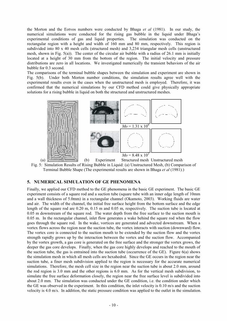
- 10 -
the Morton and the Eotvos numbers were conducted by Bhaga et al (1981). In our study, the
numerical simulations were conducted for the rising gas bubble in the liquid under Bhaga’s
experimental conditions of gas and liquid properties. The simulation was conducted on the
rectangular region with a height and width of 160 mm and 80 mm, respectively. This region is
subdivided into 80 x 40 mesh cells (structured mesh) and 3,234 triangular mesh cells (unstructured
mesh, shown in Fig. 5(a)). The center of the circular air bubble with a radius of 26.1 mm is initially
located at a height of 30 mm from the bottom of the region. The initial velocity and pressure
distributions are zero in all locations. We investigated numerically the transient behaviors of the air
bubble for 0.3 second.
The comparisons of the terminal bubble shapes between the simulation and experiment are shown in
Fig. 5(b). Under both Morton number conditions, the simulation results agree well with the
experimental results even in the cases when the unstructured mesh is employed. Therefore, it was
confirmed that the numerical simulations by our CFD method could give physically appropriate
solutions for a rising bubble in liquid on both the structured and unstructured meshes.
Mo = 1.31 x 10
0
Mo = 8.48 x 10
2
(a) (b) Experiment Structured mesh Unstructured mesh
Fig. 5: Simulation Results of Rising Bubble in Liquid: (a) Unstructured Mesh, (b) Comparison of
Terminal Bubble Shape (The experimental results are shown in Bhaga et al (1981).)
5. NUMERICAL SIMULATION OF GE PHENOMENA
Finally, we applied our CFD method to the GE phenomena in the basic GE experiment. The basic GE
experiment consists of a square rod and a suction tube (square tube with an inner edge length of 10mm
and a wall thickness of 5.0mm) in a rectangular channel (Okamoto, 2003). Working fluids are water
and air. The width of the channel, the initial free surface height from the bottom surface and the edge
length of the square rod are 0.20 m, 0.15 m and 0.05 m, respectively. The suction tube is located at
0.05 m downstream of the square rod. The water depth from the free surface to the suction mouth is
0.05 m. In the rectangular channel, inlet flow generates a wake behind the square rod when the flow
goes through the square rod. In the wake, vortices are generated and advected downstream. When a
vortex flows across the region near the suction tube, the vortex interacts with suction (downward) flow.
The vortex core is connected to the suction mouth to be extended by the suction flow and the vortex
strength rapidly grows up by the interaction between the vortex and the suction flow. Accompanied
by the vortex growth, a gas core is generated on the free surface and the stronger the vortex grows, the
deeper the gas core develops. Finally, when the gas core highly develops and reached to the mouth of
the suction tube, the gas is entrained into the suction tube (occurrence of the GE). Figure 6(a) shows
the simulation mesh in which all mesh cells are hexahedral. Since the GE occurs in the region near the
suction tube, a finer mesh subdivision applied to the region is necessary for the accurate numerical
simulations. Therefore, the mesh cell size in the region near the suction tube is about 2.0 mm, around
the rod region is 3.0 mm and the other regions is 6.0 mm. As for the vertical mesh subdivision, to
simulate the free surface deformation closely, the region near the free surface level is subdivided into
about 2.0 mm. The simulation was conducted under the GE condition, i.e. the condition under which
the GE was observed in the experiment. In this condition, the inlet velocity is 0.10 m/s and the suction
velocity is 4.0 m/s. In addition, the static pressure condition was applied to the outlet in the simulation.

- 11 -
Figures 6(b) and 6(c) show the simulation results for the free surface shape (the occurrence of the GE)
and the transient vortical velocity distributions above the suction tube, respectively. As shown in Fig.
6(b), our CFD method succeeded in reproducing the GE occurrence observed in the experiment under
the same condition. In addition, it was confirmed that the GE in the simulation result was induced by
the same mechanism with the experiment. In other words, as mentioned above, the interaction
between the vortex (free surface) and the suction flow induces the GE in the experiment, in the
simulation result (shown in Fig. 6(c)), it is evident that the growth of the suction velocity towards the
free surface extends the gas core and causes the GE. Therefore, form these simulation results, our
CFD method was validated to be applicable to the GE phenomena.
(a) (b) (c)
Fig. 6: Simulation Result of GE: (a) Simulation Mesh, (b) Occurrence of GE, (c) Transient Vertical
Velocity Distribution (m/s)
6. CONCLUSION
In this paper, we developed and validated a high-precision CFD method to evaluate the GE
phenomena accurately. First, the flow calculation method on unstructured meshes were formulated
and verified. As a result, our CFD method succeeded in calculating vortical flows accurately even on
the unstructured mesh. Second, the PLIC method was newly formulated on unstructured meshes and
verified by solving the slotted-disk rotation problem. In addition, the volume-conservative
formulation was introduced to improve the simulation accuracy on unstructured meshes. Third, the
appropriate momentum calculation method and the appropriate balance between the pressure and
surface tension were addressed to eliminate the unphysical behaviors (e.g. spurious velocity) generated
in conventional methods. Our new formulation succeeded in eliminating the unphysical behaviors
near gas-liquid interface and deriving physically appropriate solutions. Finally, the CFD method was
applied to the rising bubble problem and the GE phenomena. As a result, the simulation results of the
rising bubble in liquid agreed well with the experimental data. In addition, the occurrence of the GE
in the basic GE experiment was reproduced by the simulation. These validation results show that our
CFD method is confirmed to be applicable to the numerical simulation of the GE phenomena.
REFERENCES
A. A. Amsden, F. H. Harlow, “The SMAC method: a numerical technique for calculating
incompressible fluid flows”, Technical Report LA-4370, Los Alamos National Laboratory, (1970).
T. J. Barth, D. C. Jespersen, “The Design and Application of Upwind Schemes on Unstructured
Meshes”, 27th Aerospace Sciences Meeting, AIAA-89-0366, (1989).
J. B. Bell, P. Colella, H. M. Glaz, “A second order Projection Method for the incompressible
Navier-Stokes Equations”,J. Comput. Phys. 85 (1989) 257-283
D. Bhaga, M. E. Weber, “Bubbles in viscous liquid: shapes, wakes and velocities”, J. Fluid. Mech.,
105, 61-85 (1981).
S. Cummins, M. M. Francois, D. B. Kothe, “Estimating curvature from volume fractions”, Computer
& Structure, 83 425-434 (2005).
Suction Tube
Square Rod
Flow Direction
0.30 0.00 -0.30
0.30 0.00 -0.30
0.30 0.00 -0.30
0.30 0.00 -0.30

- 12 -
L. L. Daggett, G. H. Keulegan, “Similitude in Free-Surface Vortex Formations”, Journal of the
Hydraulics Division, Proceedings of the ASCE, Vol. 100, No. HY8 (1974).
Y. Eguchi, K. Yamamoto, T. Funada, N. Tanaka, S. Moriya, K. Tanimoto, K. Ogura, K. Suzuki, I.
Maekawa, “Gas Entrainment in the IHX of Top-Entry Loop-Type LMFBR”. Nucl. Eng. Des., 146,
373-381 (1984).
M. M. Francois, S. J. Cummins, E. D. Dendy, D. B. Kothe, J. M. Sjicilian, M. W. Williams, “A
balanced force algorithm for continuous and sharp interfacial surface tension models within a
volume tracking framework”, J. Comput. Phys., 213, 141-173 (2006).
U. GHIA, K. N. GHIA, C. T. SHIN, “High-Re Solutions for Incompressible Flow Using the Navier-
Stokes Equations and a Multigrid Method”, J. Comput. Phys., 48, 387-411 (1982).
D. J. E. Harvie, D. F. Fletcher, “A New Volume of Fluid Advection Algorithm: The Stream Scheme”, J.
Comp. Phys., 162, 1-32 (2000).
C. W. Hirt, D. B. Nichols, “Volume of Fluid (VOF) Method for the Dynamics of Free Boundaries”, J.
Comp. Phys., 39, 201-205 (1981).
M. Ichimiya, T. Mizuno, M. Konomura, “A Promising Sodium-Cooled Fast Reactor Comcept and its
R&D Plan”, GLOBAL 2003, New Orlens, LA, USA (2003).
S. E. Kim, B. Makarov, D. Caraeni, “A Multi-Dimensional Linear Reconstruction Scheme for
Arbitrary Unstructured Grids”, AIAA 2003-3990 (2003).
N. Kimura, K. Hayashi, M. Igarashi, H. Kamide, M. Itoh, T. Sekine, “Experimental study on flow
optimization in upper plenum of reactor vessel for a compact sodium cooled fast reactor”, Nucl.
Tech., 152, 210-222 (2005).
M. R. Maier, “Onsets of liquid and gas entrainment during discharge from a stratified air-water region
through two horizontal side branches with centerlines falling in an inclined plane”, M. Sc. Thesis,
University of Manitoba (1998).
P. A. Muzaferija, “Adaptive finite volume method for flow predictions using unstructured meshes and
multigrid approadh”, Ph.D. thesis, Univ. of London (1994).
W. F. Noh, P. Woodward, “SLIC (Simple Line Interface Calculation)”, Lecture Notes in Physics, (A. I.
van der Vooren, P. J. Zandbergen, ed.), Springer-Verlag, 330-340 (1976).
K. Okamoto, K. Takeyama, M. Iida, “Dynamic PIV Measurement for the Transient Behavior of a Free-
Surface Vortex”, Forth Japan-Korea Symposium on Nuclear Thermal Hydraulics and Safety
(NTHAS4), Sapporo, Japan, NTHAS4-097 (2004).
J. E. Pilliod, E. G. Puckett, “Second-Order Accurate Volume-of-Fluid Algorithms for Tracking Material
Interfaces”, J. Comp. Phys., 199, 465-502 (2004).
W. Rider, D. B. Kothe, “Reconstructing Volume Tracking”, J. Comp. Phys., 141,112-152 (1998).
M. Rudman, “Volume-Tracking Methods for Interfacial Flow Calculations”, Int. J. Numer. Methods
Fluids, 24, 671-691 (1997).
R. Scardvelli, S. Zaleski, “Analytical Relations Connecting Linear Interface and Volume Functions in
Rectangular Grids”, J. Comp. Phys., 164, 228-237 (2000).
M. Sussman, “A second order coupled level set and volume-of-fluid method for computing growth and
collapse of vapor bubbles”, J. Comput. Phys., 187, 110-136 (2003).
X. Yang, A. J. James, “Analytic Relations for Reconstructing Piecewise Linear Interfaces in Triangular
and Tetrahedral Grids”, J. Comp. Phys., 214, 41-54 (2006).
D. L. Young, (K. W. Morton, M. J. Baine, ed.), Numerical Methods for Fluid Dynamics. Academic
Press, 273-468 (1982).
S. T. Zalesak, “Fully Multidimensional Flux-Corrected Transport Algorithm for Fluids”, J. Comp.
Phys., 31, 335-362 (1979).
N. Zuber, “Problems in Mod eling of Small Break LOCA”, Nuclear Regulatory Commission Report,
NUREG-0724 (1980).