Development and validation of a bicycle helmet: of head ... · Carreira and Q. Allinne are...
15
Abstract Although cycling may be attractive for both economic and environmental reasons, cyclists are extremely vulnerable road users and subjected to falls or collisions with cars. This present research attempts to understand the degree of protection offered by a commercial bicycle helmet under standard impact conditions. In accordance with the EN 1078 standard, an experimental program has been carried out on an existing helmet by performing 90 normative impacts under three different types of conditionings. In parallel, this helmet has been digitalized and meshed to get a finite element model (FEM) that has been implemented under the LS‐ DYNA® crash code. The experimental tests have been numerically reproduced in order to provide an in‐depth validation of the helmet model under each of the 90 experimental impacts. The bicycle helmet model was finally coupled to a detailed human head model in order to compute intra‐cranial field parameters and to assess the head injury risk. Results show that the calculated intra‐cranial parameters were higher than previously published human head tolerance limits in terms of diffuse axonal injuries (DAI) and subdural hematoma (SDH) illustrating thus the critical level of loading under standard helmet test conditions. Specific mass (kg/m 3 ) E Young’s modulus (MPa) unloading E Unloading modulus (MPa) Poisson’s coefficient (‐) Keywords: Bicycle helmet, Helmet modeling, Head modeling, Head injuries, Standards I. INTRODUCTION Cycling represents one of the most popular recreational sports, but also one of the main transportation means all over the world and more specifically in urban areas. As reported by the United Nations in 2003 [1], road traffic injuries caused the death of more than one million humans in year 2000, representing the ninth highest cause of death worldwide. Many previous studies have outlined the effectiveness of wearing bicycle helmets [2]‐[3] and also the possibility of the improvement of currently used helmet design [4]‐[5]. According to Belgian statistics published in a recent survey [6], 9.6% of the study subjects in 1999 took a ride on their bikes. From this percentage, 7.3% used the bike as their main method of transportation to work and 19.2% to school. In 2000, a total of 6655 injuries and 134 fatalities were attributed to cycling accidents in Belgium on public roads. 9.8% of all road accidents and 9.1% of road traffic deaths were represented by pedal cyclists. The head represents the most vulnerable part of the human body and one of the most important to be protected. Between 21‐61% of the victims of bicycle accidents seeking medical care have a head injury as reported by Collins et al. in 1993 [7] and Eilert‐Petersson & Schelp in 1997 [8]. The medical care required by this large number of victims also implies high costs both economical and societal. Bicycling dramatically leads to increased numbers of fatalities due to head injuries which represent the cause of death in 69–93% of fatal accidents according to Oström et al. [9]. Therefore, wearing a helmet is of crucial and vital importance considering this high percentage of head trauma in cyclists. G. Milne is PhD student in the biomechanic team at Strasbourg University in France, C. Deck, N. Bourdet and R. Willinger are respectively PhD researchers and Professor in the same team ([email protected]), Phone: +33.(0)3.68.85.29.40, Fax: +33(0)3.68.85.29.36. R.P. Carreira and Q. Allinne are respectively research and development laboratory manager and R&D engineer at Oxylane in Villeneuve d’Ascq (France) Development and validation of a bicycle helmet: Assessment of head injury risk under standard impact conditions G. Milne 1 , C. Deck 1 , N. Bourdet 1 , R.P. Carreira 2 , Q. Allinne 2 , R. Willinger 1 IRC-12-86 IRCOBI Conference 2012 - 813 -
-
Upload
hoangkhuong -
Category
Documents
-
view
217 -
download
0
Transcript of Development and validation of a bicycle helmet: of head ... · Carreira and Q. Allinne are...
Abstract Although cycling may be attractive for both economic and environmental reasons, cyclists are
extremely vulnerable road users and subjected to falls or collisions with cars. This present research attempts to
understand the degree of protection offered by a commercial bicycle helmet under standard impact conditions.
In accordance with the EN 1078 standard, an experimental program has been carried out on an existing helmet
by performing 90 normative impacts under three different types of conditionings. In parallel, this helmet has
been digitalized and meshed to get a finite element model (FEM) that has been implemented under the LS‐
DYNA® crash code. The experimental tests have been numerically reproduced in order to provide an in‐depth
validation of the helmet model under each of the 90 experimental impacts. The bicycle helmet model was
finally coupled to a detailed human head model in order to compute intra‐cranial field parameters and to assess
the head injury risk. Results show that the calculated intra‐cranial parameters were higher than previously
published human head tolerance limits in terms of diffuse axonal injuries (DAI) and subdural hematoma (SDH)
illustrating thus the critical level of loading under standard helmet test conditions.
Specific mass (kg/m3)
E Young’s modulus (MPa)
unloadingE Unloading modulus (MPa)
Poisson’s coefficient (‐)
Keywords: Bicycle helmet, Helmet modeling, Head modeling, Head injuries, Standards
I. INTRODUCTION
Cycling represents one of the most popular recreational sports, but also one of the main transportation means all over the world and more specifically in urban areas. As reported by the United Nations in 2003 [1], road traffic injuries caused the death of more than one million humans in year 2000, representing the ninth highest cause of death worldwide. Many previous studies have outlined the effectiveness of wearing bicycle helmets [2]‐[3] and also the possibility of the improvement of currently used helmet design [4]‐[5]. According to Belgian statistics published in a recent survey [6], 9.6% of the study subjects in 1999 took a ride on their bikes. From this percentage, 7.3% used the bike as their main method of transportation to work and 19.2% to school. In 2000, a total of 6655 injuries and 134 fatalities were attributed to cycling accidents in Belgium on public roads. 9.8% of all road accidents and 9.1% of road traffic deaths were represented by pedal cyclists.
The head represents the most vulnerable part of the human body and one of the most important to be protected. Between 21‐61% of the victims of bicycle accidents seeking medical care have a head injury as reported by Collins et al. in 1993 [7] and Eilert‐Petersson & Schelp in 1997 [8]. The medical care required by this large number of victims also implies high costs both economical and societal. Bicycling dramatically leads to increased numbers of fatalities due to head injuries which represent the cause of death in 69–93% of fatal accidents according to Oström et al. [9]. Therefore, wearing a helmet is of crucial and vital importance considering this high percentage of head trauma in cyclists.
G. Milne is PhD student in the biomechanic team at Strasbourg University in France, C. Deck, N. Bourdet and R. Willinger are respectively PhD researchers and Professor in the same team ([email protected]), Phone: +33.(0)3.68.85.29.40, Fax: +33(0)3.68.85.29.36. R.P. Carreira and Q. Allinne are respectively research and development laboratory manager and R&D engineer at Oxylane in Villeneuve d’Ascq (France)
Development and validation of a bicycle helmet: Assessment of head injury risk under standard impact conditions
G. Milne1, C. Deck1, N. Bourdet1, R.P. Carreira2, Q. Allinne2, R. Willinger1
IRC-12-86 IRCOBI Conference 2012
- 813 -

The bicycle helmet protects the head against injury by reducing the impact energy that is transmitted to the head through energy absorption and dissipation through elastic and plastic deformation of its components (external shell and foam liner) and by increasing the area over which the impact is distributed. To be homologated and then sold, the helmet must pass a series of tests imposed by standards such as the EN 1078 in Europe [10]. This standard requires the helmet to be subjected to an energy absorption test consisting of linear impacts on both flat and kerbstone anvils at velocities of 5.42 m/s and 4.57 m/s respectively. For each impact, the helmet is fitted to a rigid ISO headform complying with the EN 960 requirements [11]. Linear accelerations along the three axes are recorded at the centre of gravity of the headform at the time of impact and the computed peak resultant linear acceleration must not exceed 250 g.
The present study aims at assessing a commercial bicycle helmet under normative impacts by means of both experimental and numerical methods. The literature reports a number of bicycle helmet models such as Willinger et al. in 1998 [12], Gilchrist & Mills in 2008 [13] and Asiminei et al. in 2009 [14]. None of them however provided a detailed validation against a number of impact points. Moreover, none of them were coupled to a human head FE model for a detailed head injury risk assessment against different injury mechanisms. In this context, the present paper reports a bicycle helmet modeling effort followed by a detailed validation against 90 experimental impact tests. Once validated, the helmet model has been coupled to an existing human head model (the Strasbourg University Finite Element model or SUFEHM) in order to compute the intra‐cranial field parameters such as brain pressure, Von Mises stress and global energy of the CSF under normative test conditions. This step resulted in an original head injury risk assessment and an evaluation of the degree of protection offered by such a commercial bicycle helmet.
II. METHODS
Experimental Approach
As a first step and in accordance with the EN 1078 standard, an experimental program was carried out to perform impacts on a commercial bicycle helmet illustrated in Fig. 1. An moulded fabrication process allowed the external polycarbonate (PC) shell to be glued to an expanded polystyrene (EPS) foam liner of density 77 kg/m3. The shapes are sharp and numerous vent holes are designed leading to a total mass of 0.235 kg.
Fig. 1. Lateral view of the helmet
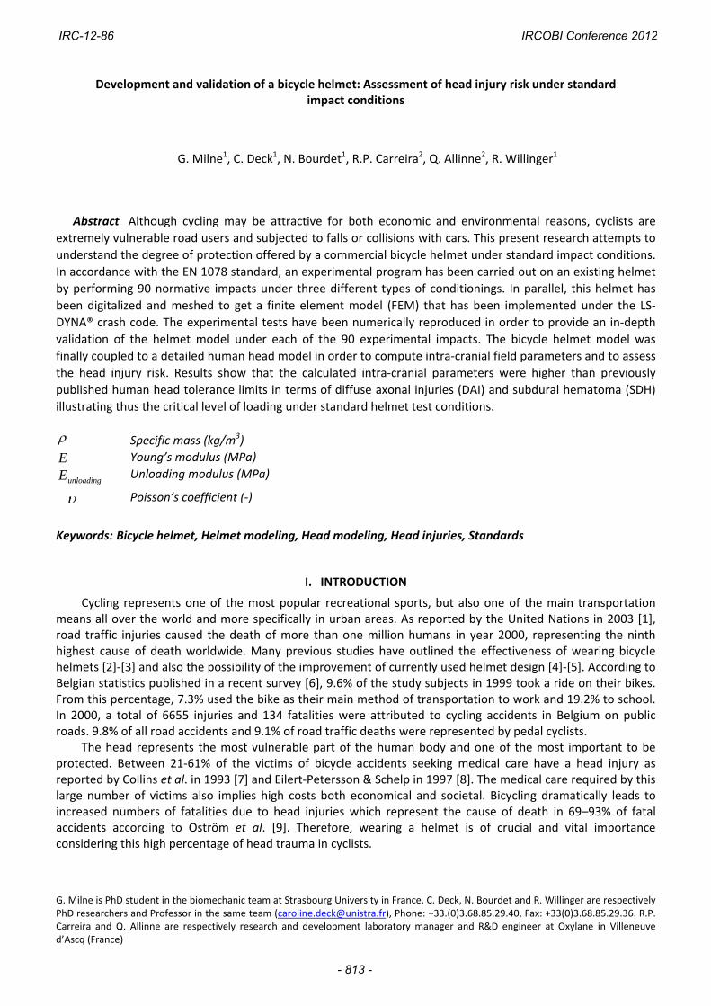
To assess the dynamic energy absorption characteristics of such a helmet in case of impact, an automatic electro‐pneumatic shock absorption test equipment with a falling speed up to 8 m/s was used. This monorail experimental device complying with the EN 1078 is presented in Fig. 2a. The helmet was positioned on an instrumented magnesium alloy complete headform (Fig. 2b) in compliance with the EN 960 standard and the retention strap was tightly clamped to maintain the coupled head‐helmet system during the test. A PCB 353/B17‐3D triaxial accelerometer placed at the centre of gravity of the headform allowed the capture of the linear accelerations along the three axes for values up to 500 g. The sensor was linked to an ISO 6487 [15] certified TDAS PRO LAB data recorder equipped with a 250 kHz Sensor Input Module (SIM) card. The TDAS Control software installed on the computer provided tools for performing data collection and display.
IRC-12-86 IRCOBI Conference 2012
- 814 -
(a) (b) Fig. 2. Test apparatus used to perform experimental impact tests: (a) Monorail shock absorption test equipment
(overall dimensions including base: mm. 860x800x5500), (b) Magnesium alloy complete headform
The resultant linear acceleration versus time curve was calculated according to equation (1) and filtered by a CFC filter with a 1 kHz cutoff frequency.
tttt zyx222
(1)
where t is the resultant linear acceleration (g), tx is the linear acceleration in x‐axes (g), ty is the
linear acceleration in y‐axes (g) and tz is the linear acceleration in z‐axes (g)
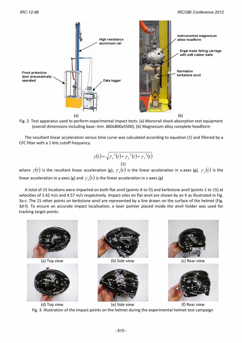
A total of 15 locations were impacted on both flat anvil (points A to O) and kerbstone anvil (points 1 to 15) at
velocities of 5.42 m/s and 4.57 m/s respectively. Impact sites on flat anvil are shown by an X as illustrated in Fig. 3a‐c. The 15 other points on kerbstone anvil are represented by a line drawn on the surface of the helmet (Fig. 3d‐f). To ensure an accurate impact localisation, a laser pointer placed inside the anvil holder was used for tracking target points.
(a) Top view (b) Side view (c) Rear view
(d) Top view (e) Side view (f) Rear view
Fig. 3. Illustration of the impact points on the helmet during the experimental helmet test campaign
IRC-12-86 IRCOBI Conference 2012
- 815 -

Before the impacts were performed, each of the 45 helmets were conditioned under one of the three following environmental conditionings:
(‐20 ± 2) °C in a BINDER 240L freezer for 4h to 6h
(+50 ± 2) °C in BINDER M400 incubator for 4h to 6h
Wet condition at ambient temperature: the helmet is placed under a shower for 4h to 6h To comply with the EN 1078 requirements, all locations around the helmet were impacted under cold, hot and wet conditions so that a total number of 90 normative impact tests were performed experimentally.
Computational Modeling
The helmet under study was digitalized to get a Computer‐Aided Design (CAD) of its geometry. The
developed helmet model consists of two parts i.e. an external shell and a liner. The CAD was automatically
meshed under the PAMCRASH® Mesh module. 4535 2D trias elements were created for the shell and 24380 3D
tetras elements for the lining. Hence, the complete helmet FEM consists of 28915 elements. The whole model is
presented in Fig. 4. Shell elements have a minimum and maximum size of 2.35 mm and 7.5 mm respectively.
Concerning brick elements, the minimum element size is 2 mm. Finally, the meshing was generated to ensure a
mesh continuity between the external shell and the liner.
Fig. 4. General view of the bicycle helmet finite‐element model
The mesh was imported under the LS‐DYNA® explicit crash code and the material properties of the two
helmet model’s parts were implemented. It was observed that under impact, the compressed EPS foam liner
produces large deformations. In order to simulate such deformations, the EPS behavior was modeled by a
tabulated "MAT_CRUSHABLE_FOAM" material law. The material properties implemented in the model were
based on EPS sample tests and summarized in table 1. The plastic behavior of the EPS was modeled by a unique
stress versus strain curve according to environmental conditions and corresponding to a dynamic loading of the
material (Fig. 5). It can be observed that at low temperature, the material is stiffer than at high temperature or
under wet condition. The Poisson’s coefficient of the foam was set close to zero due to its very high
compressibility. The slope of the unloading curve was set to 28 MPa accordingly to Tinard et al. [16].
Table 1. Mechanical properties of the EPS foam
ρ (kg/m3) 61.6
Eunloading (MPa) 28
ν (‐) 0.01
IRC-12-86 IRCOBI Conference 2012
- 816 -

Fig. 5. Tabulated curves implemented in the material law
A linear elastic behavior was selected for the polycarbonate (PC) shell and modeled by the “MAT_ELASTIC”
law. The values of the three parameters needed to characterize the PC material were extracted from the
literature [17] and are reported in table 2. A measured thickness value of 1.18 mm was attributed to all shell
elements.
Table 2. Mechanical properties of the PC shell
ρ (kg/m3) 1055
E (MPa) 15000
ν (‐) 0.42
To reproduce the 90 normative experimental tests, an ISO headform FEM was imported under the LS‐DYNA®
environment. This 5.7 kg headform was meshed with 3280 quadrilateral 4‐nodes shell elements as shown in Fig. 6. The rigid behavior of its constitutive material was defined by the “MAT_RIGID” law with Poisson’s coefficient and Young’s modulus set to 0.2 and 200 GPa respectively.
The head‐helmet contact of the coupled system illustrated in Fig. 6 was defined by taking into account a “CONTACT_AUTOMATIC_SURFACE_TO_SURFACE” interface with a 0.2 friction coefficient.
Fig. 6. Illustration of the headform model coupled to the bicycle helmet model
Two anvil models, flat (306 brick elements) and kerbstone (2820 brick elements), were created to perform
the numerical impacts on both surfaces according to the experimental approach, as it can be observed in Fig. 7. The geometry and the dimensions of the flat anvil comply with the EN 1078 prescriptions (minimum diameter of (125 ± 3) mm and 24 mm thick), as do the kerbstone anvil (angle of 90 ± 0.5°, 50 mm minimum height and 200 mm minimum length). The “MAT_ELASTIC” material law and the parameter values as mentioned in table 3 are the same for both impacted surfaces. A "CONTACT_AUTOMATIC_NODE_TO_SURFACE" interface with a friction coefficient of 0.1 was defined to compute the shocks on the two anvils.
Table 3. Mechanical properties of the flat/kerbstone anvil
ρ (kg/m3) 7800
E (MPa) 200000
ν (‐) 0.3
IRC-12-86 IRCOBI Conference 2012
- 817 -

(a) (b) Fig. 7. Illustration of the simulation of standard impact tests against two anvils: (a) Flat anvil, (b) Kerbstone
anvil
In order to assess the risk of head trauma in terms of diffuse axonal injury (DAI) and subdural hematoma (SDH) under normative impacts, a coupling between the bicycle helmet FEM and the Strasbourg University Finite Element Model (SUFEHM) was performed under the LS‐DYNA® software. This model developed by Kang et al. in 1998 [18] and illustrated in Fig. 8 was meshed with 10395 brick elements and 2813 shell elements. Based on anatomical atlas, the head model contains the face, scalp, skull and a homogenous brain. Intra‐cranial membranes and cerebrospinal fluid (CSF) are also represented in this model. The constitutive material laws of the different parts of the model have been defined by the material laws specified in appendix 1 according to Willinger et al. (1998) [19]. This model was validated under dynamic experimental tests reported by Nahum et al. (1977) [20], Trosseille et al. (1992) [21] and Yoganandan et al. (1994) [22]. This head model has been extensively used for the simulation of a number of well documented real world head trauma in order to correlate intra‐cranial mechanical parameters with the occurence of injury. This approach permitted us to define model based head injury criteria reported by Deck et al. in 2008 [23], as follows:
50% risk of moderate neurological injury (DAI1+): Brain Von Mises shearing stress of 28 kPa
50% risk of severe neurological injury (DAI2+): Brain Von Mises shearing stress of 53 kPa
50% risk of subdural hematoma: CSF strain energy of 4950 mJ
The interface between the energy absorbing foam and the human head model (Fig. 9a) was computed by an “AUTOMATIC_NODE_TO_SURFACE” LS‐DYNA® contact with a friction coefficient set to 0.2. An example of positioning of the coupled head‐helmet system for a lateral impact on a flat anvil is shown in Fig. 9b.
Fig. 8. Strasbourg University Finite Element Head Model
IRC-12-86 IRCOBI Conference 2012
- 818 -

(a) (b)
Fig. 9. Helmet‐SUFEHM coupling: (a) Illustration of the head‐helmet interface, (b) Positioning of the coupled system for a normative impact on flat anvil
III. RESULTS
During the validation process, each of the 30 helmet target points was impacted experimentally and
numerically under three environmental conditionings (‐20°C, +50°C and humidity). The numerical resultant
linear acceleration was computed at the centre of gravity of the headform in order to superimpose it with the
experimental result. In the framework of this in‐depth helmet validation effort, results in terms of resultant
linear acceleration versus time curve were superimposed with experimental results as well as the peak values.
An illustration is given for a crown impact (point C) at 5.42 m/s on a flat anvil under low temperature, high
temperature and under humidity treatment in Fig. 10. A good agreement is observed in terms of time duration
(8 ms) and peak resultant linear acceleration demonstrating that the stress‐strain curve defined for each
condition is well suited to the energy absorbing material in the considered loading case. Numerical peak g is 163
g, 166 g and 174 g under ‐20°C, +50°C and H20 condition respectively. Related experimental values are 169 g,
161 g and 165 g leading to 3.7%, 3.0% and 5.2% relative errors.
(a) (b)
(c) Fig. 10. Superposition of experimental and numerical headform acceleration under crown impact at 5.42 m/s
against a flat anvil: (a) Cold condition, (b) Hot condition, (c) Wet condition
IRC-12-86 IRCOBI Conference 2012
- 819 -

Time history resultant linear accelerations obtained for a frontal impact (point 1) on kerbstone anvil are
shown in Fig. 11 under cold, hot and humid conditionings. By analyzing the time durations (12 ms) and peak
values between numerical and experimental results, a good agreement is also observed. Numerical simulation
of impacts tests led to peak values of 76 g at ‐20°C, 88 g at +50°C, 83 g under humidity condition. Compared to
experimental values, relative errors are respectively 5.3%, 13.6% and 2.4%.
(a) (b)
(c) Fig. 11. Superposition of experimental and numerical headform acceleration under frontal impact at 4.57 m/s
against a kerbstone anvil: (a) Cold condition, (b) Hot condition, (c) Wet condition
Results for 38 impact configurations obtained by impacting the helmet on a flat anvil are shown in Fig. 12 for
the experimental and numerical approach. The validity of all simulations has been checked by comparing both
hourglass and total energy of the system. To do so, the hourglass energy that is a numerical energy reflecting
calculation errors must be lower than 10% of the total energy. In terms of peak resultant linear acceleration, a
good agreement is particularly seen for points A to F under each of the three conditionings. Nonetheless, the
theoretical acceleration is overestimated for points G and H. This artefact can be explained by the extreme
sensitivity of the model response to the positioning of the helmet towards the anvil. Another reason which can
explain these differences in peak values is that rupture and high shear deformations of the EPS liner appear
when impacting these critical points, phenomena which are not taken into account in the present material
model. Missing points (I and L) are points for which numerical instabilities have been observed and for similar
reasons.
IRC-12-86 IRCOBI Conference 2012
- 820 -

(a) (b)
(c) Fig. 12. Comparison of experimental and computed maximum headform acceleration under impacts against
the flat anvil: (a) Cold condition, (b) Hot condition, (C) Wet condition
A comparison between experimental and numerical peak acceleration values for impacts on kerbstone anvil
at 4.57 m/s velocity and under all conditionings is presented in Fig. 13‐14. For the 35 impact configurations,
results show a good agreement between experimental and numerical data. Missing points, respectively points
12, 14 and 15 under all environmental conditions, led to numerical instabilities and hourglass energies higher
than 10% of the total energies probably due to rupture as pointed out previously. It should be mentioned that
for all impacts, the peak resultant linear acceleration never exceeded the EN 1078 acceleration limit fixed at 250
g.
(a) (b) Fig. 13. Comparison of experimental and computed maximum headform acceleration under impacts against
the kerbstone anvil: (a) Cold condition, (b) Hot condition
IRC-12-86 IRCOBI Conference 2012
- 821 -

Fig. 14. Comparison of experimental and computed maximum headform acceleration under impacts against the kerbstone anvil under wet condition
When coupled to the human head model, intra‐cranial parameters have been computed in order to assess
the injury risks in terms of diffuse axonal injury and subdural hematoma under normative impacts in accordance
with the model based injury criteria presented in the Methods section.
As for the numerical simulations with the headform model, the validity of each simulation has been verified
by comparing both hourglass and total energy of the system. Still, hourglass energy must be lower than 10% of
the total energy involved.
The peaks Von Mises intra‐cerebral stress computed under impact on both flat and kerbstone anvils for all
target points and under the three normative conditionings are shown in Fig. 15. Generally speaking, most of the
impact points led to significant but acceptable brain shearing. For normative impacts on kerbstone anvil, Fig.
15b also shows that the Von Mises stress calculated for each impact is lower than 28 kPa leading to a
percentage of moderate DAI risk less than 50% for all impact configurations. Injury assessment in terms of
percentage of risk to sustain a moderate DAI for the helmeted head impacting a flat or a kerbstone anvil are
presented respectively in appendix 2 and appendix 3.
Results obtained in terms of internal strain energy within the CSF layer for impacts on flat and kerbstone
anvils, both under the three environmental conditionings, are presented in Fig. 16. Risks for the helmeted user
to suffer from a SDH in terms of percentage of risk after impacting a flat surface under normative impact
conditions are mentioned in appendix 4. As demonstrated in Fig. 16b, impacts realized on kerbstone anvil led to
injury risk far below 50%, with a maximum risk of SDH of 5% obtained by impacting the point 2 under cold
conditioning as it appears in appendix 5.
(a) (b) Fig. 15. Peak intra‐cerebral shearing stress computed with the helmet model coupled to the human head
model for all impact points: (a) Flat anvil, (b) Kerbstone anvil
IRC-12-86 IRCOBI Conference 2012
- 822 -

(a) (b) Fig. 16. Peak CSF strain energy computed with the helmet model coupled to the human head model for all
impact points: (a) Flat anvil, (b) Kerbstone anvil
IV. DISCUSSION
This paper proposes a detailed FE model of an existing commercial bicycle helmet. Based on strict requirements imposed by the EN 1078 standard, numerical simulations were performed and a comparison against 90 experimental impact tests in terms of peak resultant linear acceleration was carried out in order to validate the helmet model under three conditionings and against flat and kerbstone anvils. Even though a number of bicycle helmet models are reported in the literature, such an in‐depth validation has never been undertaken to the authors’ knowledge.
For most of the impact points, whether on flat or kerbstone anvil, a very good agreement has been shown with relative errors remaining under 10%. Such results are typically obtained for frontal and crown impacts. However, it must be mentioned that for a limited number of points such as points G, H and M mainly located in lateral or occipital regions, relative errors are less acceptable. The reason of this situation may be due to a very high sensitivity of the headform response to the position of the impact site on the helmet and the direction of the impact as non controlled rotation may be introduced. Another possible reason for errors between experiment and simulation for such critical impact points is that under lateral impact, the helmet presents cracks due to an extreme material loading, a phenomenon which is not taken into consideration in the current material constitutive law.
As LS‐DYNA® material law implemented in the model to reproduce the compression of the foam liner does not take into account any shear deformations or cracks of the EPS, further improvement of the EPS material law is needed in order to progress towards a more realistic helmet model under lateral impact.
Even if current bicycle helmets are designed to reduce headform acceleration, they are still not optimized to reduce human head injuries. In order to progress towards this final objective, head injury risk assessment under standard impact conditions was undertaken in this study. It appears that, for the validated impact points, the head injury risk is quite limited. It should be mentioned that the risk of skull fracture was not considered in the present study and that a few lateral impact points clearly need further investigations.
The head injury risks have been investigated only in case of normal impacts but accident analysis shows [24] that most of the bicycle helmet impacts are oblique, with the most common impact sites located at the front and sides of the helmet [25] causing both linear and rotational accelerations to the head. In bicycle helmet test standards, test impacts are perpendicular to the surface of fixed anvils, and the peak headform linear acceleration is used as a pass/fail criterion. Helmet standards currently in use today do not measure any rotational effects to the headform. However, rotational head acceleration results in large shear strains arising in the brain, a phenomenon which should be taken into account in further helmet investigations by developing a validated helmet model against experimental oblique impact tests in terms of both peak linear and rotational accelerations. A number of technological solutions already exist (crushing material or structural decoupling) in order to reduce head rotational acceleration. Coupling this potential validated model to the anatomic head, it would then be possible to optimize the helmet against life‐threatening rotational effects to the brain.
IRC-12-86 IRCOBI Conference 2012
- 823 -
V. CONCLUSIONS
In this study, a finite‐element model of a brand new bicycle helmet was developed, implemented and validated under the LS‐DYNA® explicit crash code.
The numerical simulation of 90 experimental normative impact tests, under three environmental conditionings and two anvils, was performed by coupling the helmet FEM to a rigid 5.7 kg ISO headform complying with the EN 960 standard. Results in terms of headform acceleration time‐history and peak g values between experiment and simulation are in good agreement for most of the impact points thus validating the helmet model. However, for impact points located laterally and close to the helmet edge, further improvement of the helmet model is needed.
Once validated, this helmet FE model was coupled to the Strasbourg University FE Head Model in order to
assess the head injury risks of both DAI and SDH injuries. Results show that normative impacts on flat anvil are
more critical than impacts against kerbstone anvil. Results also show that the computed injury risk is acceptable
for most of the impact points. This work is therefore a step towards both helmet optimisation against
biomechanical head injury criteria and the consideration of model based head injury criteria into future helmet
standards.
VI. ACKNOWLEDGEMENT
This work has been developed within the ANR PREDIT Project “BICYTETE” led by the French department of
Transport.
VII. REFERENCES
[1] United Nations, Internet: www.un.org/Pubs/chronicle/2003/issue2/0203p78.html [2] Thompson R.S., Rivara F.P., Thompson D.C., A case control‐study of the effectiveness of bicycle safety
helmets. N. Engl. J. Med., 320: 1361‐136, 1989 [3] Thomas S., Acton C., Nixon J., Battistutta D., Pitt W.R., Clark R., Effectiveness of the bicycle helmets in
preventing the head injury in children: case control study. Brit. Med. J., 308: 173‐176, 1994
[4] McIntosh A.S., Kallieris D., Mattern R., Svensson N.L., Dowdell B. An evaluation of pedal cycle helmets performance requirements. Proc, 39th Stapp Car Crash Conference, San Diego, USA, pp. 111‐119, 1995
[5] Ching R.P., Thompson D.C., Thompson R.S., Thomas D.J., Chillcott W.C., Rivara F.P., Damage to bicycle helmets involved with crashes. Accid. Anal. Prev., 29: 555‐562, 1997
[6] NIS (Statistics Belgium), Mobiliteit 1998–1999, Brussels, 2000
[7] Collins B.A., Langley J.D., Marshall S.W., Injuries to pedal cyclists resulting in death and hospitalisation. N Z Med J, 106(969): 514‐516, 1993
[8] Eilert‐Petersson E., Schelp L., An epidemiological study of bicycle‐related injuries, Accid. Anal. Prev., 29(3): 363‐372, 1997
[9] Oström M., Björnstig U., Näslund K., Eriksson A., Pedal cycling fatalities in Northern Sweden. Int J Epidemiol., 22: 483‐488, 1993
[10] NF EN 1078 standard, Helmets for pedal cyclists and for users of skateboards and roller skates, S 72‐403, 1997
[11] EN 960 standard, Headforms for use in the testing of protective helmets, 1995
[12] Willinger R., Diaw B.M., Baumgartner D., Development and validation of a bicycle helmet finite element model, Proceedings of IRCOBI Conference, Göteborg, Sweden, pp549‐552, 1998
[13] Gilchrist A, Mills N.J., Finite‐element analysis of bicycle helmet oblique impacts, Int. J. Impact Engng 35, 1087‐1101, 2008
IRC-12-86 IRCOBI Conference 2012
- 824 -
[14] Asiminei A.G., Van der Perre G., Verpoest I., Goffin J., A transient finite element study reveals the importance of the bicycle helmet material properties on head protection during an impact, Proceedings of IRCOBI Conference, York, United Kingdom, pp. 357‐360, 2009
[15] ISO 6487 standard, Road vehicles ‐ Measurement techniques in impact tests ‐ Instrumentation, 2002
[16] Tinard V., Deck C., Willinger R., Modelling and validation of motorcyclist helmet with composite shell, Int J. Crash, DOI:10.1080/13588265.2011.648465, 2012
[17] Deck C., Willinger R., Multi‐directional optimisation against biomechanical criteria of a head‐helmet coupling, Int J Crash, 11(6):561‐72, 2006
[18] Kang H.S., Willinger R., Diaw B.M.,Chinn B., Validation of a 3D human head model and replication of head impact in motorcycle accident by finite element modeling. Proc. 41th Stapp Car Crash Conference, Lake Buena Vista, USA, pp. 329‐338, 1997
[19] Willinger R., Diaw B.M., Kang H.S., Finite element modeling of the human head ‐ Modal and temporal validation, Int Conf on Vib Eng, Dalian, China, 1998
[20] Nahum A.M., Smith R., Warg C.C., Intracranial pressure dynamics during head impact, Proc. 21th Stapp Car Crash Conference, New Orleans, USA, pp. 337‐366, 1977
[21] Trosseille X., Tarriére C., Lavaste F., Guillon F., Development of a FEM of the human head according to a specific test protocol, Stapp Car Crash Conf, Seattle, USA, 1992
[22] Yoganandan N., Pintar F.A., Sances A., Walsh P.R., Ewing C.L., Thomas D.T., Snyder R.G., Biomechanics of skull fracture, Journal of Neurotrauma, Vol.12, No. 4/ 659‐668, 1995
[23] Deck C., Willinger R., Improved head injury criteria based on head FE model, Int J Crash, Vol. 13, No. 6, pp. 667‐678, 2008
[24] Otte D., Injury mechanism and crash kinematics of the cyclists in accident, Proc. 33th Stapp Car Crash Conference, Washington DC, USA, pp. 1‐20, 1989
[25] Larsen L.B., Epidemiology of bicyclist’s injuries, Proceedings of the IRCOBI Conference, Berlin, Germany, pp. 217–30, 1991
IRC-12-86 IRCOBI Conference 2012
- 825 -

VIII. APPENDIX
APPENDIX 1. MECHANICAL PROPERTIES OF THE SUFEHM CONSTITUTIVE PARTS
Segment Illustration Mechanical behavior
Mechanical parameters
Mechanical parameters
Falx and Tent
Linear elastic
e = 1 mm
ρ = 1140 kg/m3
E = 31.5 MPa
υ = 0.45
/
Brain‐Skull interface
Linear elastic
ρ = 1040 kg/m3
E = 0.012 MPa
υ = 0.49
/
Brain and Cerebellum
Viscous elastic
ρ = 1040 kg/m3
K = 1125 MPa
G0 = 0.049 MPa
Ginf = 0.0167
β = 145 s‐1
/
Skull
Fragile elastic‐plastic
Cortical
e = 2 mm
ρ = 1900 kg/m3
E = 15000 MPa
υ = 0.21
K = 6200 MPa
UTS = 90 MPa
UTC = 145 MPa
Spongy
e = 3 mm
ρ = 1500 kg/m3
E = 4600 MPa
υ = 0.05
K = 2300 MPa
UTS = 35 MPa
UTC = 28 MPa
Face
Linear elastic
e = 10 mm
ρ = 2500 kg/m3
E = 5000 MPa
υ = 0.23
/
Skin
Linear elastic
ρ = 1000 kg/m3
E = 16.7 MPa
υ = 0.42
/
IRC-12-86 IRCOBI Conference 2012
- 826 -

APPENDIX 2. Risk of moderate DAI for all impact points on flat anvil and under three conditionings
APPENDIX 3. Risk of DAI for 12 impact points on kerbstone anvil and under three conditionings
APPENDIX 4. Risk of SDH for all impact points on flat anvil and under three conditionings
APPENDIX 5. Risk of SDH for 12 impact points on kerbstone anvil and under three conditionings
IRC-12-86 IRCOBI Conference 2012
- 827 -