Three Egg Full Auto Incubator User Manual - McMurray Hatchery

European Journal of Engineering and Technology Vol. 4 No. 2, 2016 ISSN 2056-5860
Progressive Academic Publishing, UK Page 13 www.idpublications.org
DEVELOPMENT AND TEMPERATURE CONTROL OF SMART EGG
INCUBATOR SYSTEM FOR VARIOUS TYPES OF EGG
Okpagu, P. E. & Nwosu, A. W.
Department of Electrical and Electronic Engineering Chukwuemeka Odumegwu Ojukwu University
Uli Anambra State, NIGERIA
ABSTRACT
This work is aimed at modeling, designing and developing an egg incubator system that is
able to incubate various types of egg within the temperature range of 35 – 400C. This system
uses temperature and humidity sensors that can measure the condition of the incubator and
automatically change to the suitable condition for the egg. Extreme variations in incubation
temperature affect the embryo and ultimately, post hatch performance. In this work, electric
bulbs were used to give the suitable temperature to the egg whereas water and controlling fan
were used to ensure that humidity and ventilation were in good condition. LCD is used to
display status condition of the incubator and an interface (Keypad) is provided to key in the
appropriate temperature range for the egg. To ensure that all part of the eggs was heated by
the lamp, DC motor was used to rotate iron rod at the bottom side and automatically change
position of the egg. The entire element is controlled using AT89C52 Microcontroller. The
temperature of the incubator is maintained at the normal temperature using PID controller
implemented in microcontroller. Mathematical model of the incubator, actuator and PID
controller were developed. Controller design based on the models was developed using
Matlab Simulink. The models were validated through simulation and the Zeigler-Nichol
tuning method was adopted as the tuning technique for varying the temperature control
parameters of the PID controller in order to achieve a desirable transient response of the
system when subjected to a unit step input. After several assumptions and simulations, a set
of optimal parameters were obtained at the result of the third test that exhibited a
commendable improvement in the overshoot, rise time, peak time and settling time thus
improving the robustness and stability of the system.
Keyword: Egg Incubator System, AT89C52 Microcontroller, PID Controller, Temperature
Sensor.
INTRODUCTION
Incubation is the process of keeping the fertilized eggs warm in order to allow proper
development of the embryo into a chick. It may either be natural or artificial. In natural
incubation, the bird provides the required conditions for the relatively few eggs she lays by
sitting on the eggs intermittently until they hatch in an open space. An artificial incubator is a
chamber in which temperature, humidity and ventilation are controlled for the purpose of
hatching a relatively large number of eggs than a single hen can handle at a time [1]. The heat
required for incubation is usually provided by coal, oil, gas or electricity.
The need for artificial incubator is to generally increase hatchability of eggs which leads to
the improvement and increase in the production of chicks and eggs for human consumption
and the economic market [2]. In this present age of information technology, the control and
automation of devices, machines and systems are mostly achieved through mechatronic
means with emphasis on soft control, this is mostly achieved by the use of programmed
microcontrollers [3]. The main aim of this work is to model, design and develop an incubator
system that is capable of incubating various types of egg within the temperature range of 35 –

European Journal of Engineering and Technology Vol. 4 No. 2, 2016 ISSN 2056-5860
Progressive Academic Publishing, UK Page 14 www.idpublications.org
400C by setting both the minimum and maximum temperature using the input interface. This
can be achieved using the following embedded components such as temperature sensor
(LM35) for sensing the temperature condition of the incubator, weight sensor for monitoring
the development of the chicks, AT89C59 microcontroller for programming of the operation
sequence of the entire system, 60watts electric bulbs for supplying of heat to the incubator,
5volts and 12volts relays, LCD, NPN-transistors, DC motor etc.
SYSTEM DESIGN
SYSTEM OPERATION
The Sensors
The LM35 has an advantage over linear temperature sensors calibrated in ˚ Kelvin, as the
user is not required to subtract a large constant voltage from its output to obtain convenient
Centigrade scaling. The LM35 does not require any external calibration or trimming to
provide typical accuracies of ±0.25˚C at room temperature and ±0.75˚C over a full −55 to
+150˚C temperature range. Low cost is assured by trimming and calibration at the wafer level
[4]. The LM35’s low output impedance, linear output, and precise inherent calibration make
interfacing to readout or control circuitry easy. As it draws only 60 µA from its supply, it has
very low self-heating, less than 0.1˚C in still air. The LM35 is rated to operate over a −55˚ to
+150˚C temperature range. The sensor senses the temperature of the incubator and feeds the
signal output to the 2-to-1 input time multiplexer [5].
Figure 1.0: The System Block Diagram
AT89C52
TEMP.
SENSOR RELAY
RELAY
RELAY
RELAY
WEIGHT
SENSOR
MUX
ADC
POWER
ELECTRIC
LAMP
DC MOTOR
ELECTRIC
LAMP
FAN
MOTOR
KEYPAD
LCD

European Journal of Engineering and Technology Vol. 4 No. 2, 2016 ISSN 2056-5860
Progressive Academic Publishing, UK Page 15 www.idpublications.org
The Relays
The temperature control circuit consists of four relays controlled by the microcontroller. The
first two relays are used for switching the incandescent lamp to a 230 V supply, the third one
is used for switching a circulating fan to a 12 V supply. The last relay is used for switching
the gear motor for operating the egg turning mechanism. Each of the relay is triggered using a
2N2222 NPN transistor. The base of the transistor is biased from the signal output of the
microcontroller. The two 60W lamps are used for heating the air inside the incubator. The
lamps are turned ON when the temperature inside the incubator is below 37° C for chick’s
egg and is turned OFF when it exceeds 38.5° C using a relay.
The circulating fan is also triggered using a 5Volts relay and is turned ON at the same time as
the incandescent lamp. It is used for the purpose of circulating the heated air uniformly
around the chamber. A gear motor is used for operating the egg turning mechanism. The gear
motor is switched ON by a 5V relay and it rotates an elliptical cam connected to the egg
holder. A spring is used to return the holder to its initial position. The display used is a 16x2
character LCD display with HD44780U dot-matrix liquid crystal display driver and
controller. The LCD is wired in 8-bit mode.
AT89C52 Microcontroller
Since the optimum temperature for chicken egg incubation is between 37 and 38.5°C [6, 7],
the microcontroller constantly check the temperature returned from the LM35 temperature
sensor. For this, 1000 samples of the ADC are taken and their average is computed. The
temperature is computed to two decimal places using mathematical operations and a suitable
correction factor is applied to rectify an error due to the external reference voltage. If the
value of temperature lies below the optimum range, a high voltage is given through the
suitable pin of the microcontroller to the base of transistor T1 to trigger the relay.
The triggering of the relay turns ON the incandescent lamp through a 230V supply and the
circulating fan through a 12V supply. The heat from the incandescent lamp increases the
temperature of the air and this is circulated inside the incubator using the fan. This process
continues till the temperature reaches above 38.5°C. Once this range is exceeded, the relay is
turned off. The incandescent lamp and the fan get turned OFF till the temperature goes below
the lower limit again. An LED is used for fault detection, in case the temperature goes below
minimum setpoint or above maximum setpoint. An interface is provided to key in the
required minimum and maximum temperature for the egg to be incubated.
Mathematical Model of the Incubation Chamber
Assume the temperature of eggs before they are placed in the incubator to be θ1 and θ2 be the
temperature of the incubator after heat q has been transferred to the incubator causing its
initial temperature to rise. LM35 sensor is used as the sensing device to take the temperature
reading of the system and we want to know how long it takes the incubation chamber
temperature to get to its maximum allowable temperature of 38.5oC. 38.5
oC is the maximum
allowable temperature for incubating chicks’ egg. From the law of heat transfers which
states: Temperature rise is proportional to heat added [8] θ
(1.0)
c = heat capacity

European Journal of Engineering and Technology Vol. 4 No. 2, 2016 ISSN 2056-5860
Progressive Academic Publishing, UK Page 16 www.idpublications.org
By dividing both sides by dt
= Φ=
(1.1)
the rate of heat transfer into the mass of egg is Φ = and the rate is governed by the
thermal resistance between the air and the mass of the egg. This obeys a law similar to ohms
law so:
Φ =
(1.2)
Where R is the thermal resistance in Kelvin per watt
Equating for Φ we have
=
(1.3) =
(1.4) + =
(1.5)
In all system, the product of the resistance and capacitance is the time constant so we have:
+ =
(1.6)
Changing from a function of time into a function of “S” we have
s + =
(1.7)
( =
(1.8)
(S) =
(1.9)
Where τ = 120 seconds, assumed time it takes to reach maximum temperature of 38.50C
(S) =
(1.10)
Figure 1.1: Modeled block diagram of the incubation subsystem
European Journal of Engineering and Technology Vol. 4 No. 2, 2016 ISSN 2056-5860
Progressive Academic Publishing, UK Page 17 www.idpublications.org
Mathematical Model of the Controller
The Ziegler-Nichols tuning rule was applied in the design of the parallel Proportional-
Integral-Derivative controller. The PID controller was selected since it is probably the most
extensively used method in industrial process control applications. The block diagram of the
continuous PID controller is shown in figure 3.6, where, Kp is the proportional gain, Ti is the
integral time constant, and Td is the derivative time constant. The transfer function of the
standard PID algorithm is:
U (t) = Kp e(t) +
+ KpTd
[8]
(1.11)
In the s-domain, the PID controller can be written as:
U(S) = Kp [1 +
+ Td.s ] E(s)
(1.12)
The discrete form of the PID controller can be achieved by finding the Z –transform of
equation above.
U(z) = E(z)Kp [ 1 +
+ Td
]
(1.13)
Equation 3.14 can also be written as:
= a +
+ c (1 - )
(1.14)
Where
a = Kp , b =
, c =
Figure 1.2: Block Diagram of a Continuous Parallel PID Controller
System Input, R(s)
Controller Transfer
Function
G (s)
Actuator
Act(s)
Incubation Chamber
Incubation chamber
BBBBCChamber
Sout
Figure 1.3: Block Diagram of the Closed Loop Incubation Temperature Control System

European Journal of Engineering and Technology Vol. 4 No. 2, 2016 ISSN 2056-5860
Progressive Academic Publishing, UK Page 18 www.idpublications.org
SIMULATION AND RESULTS
The entire system which is made up of controller, actuator, incubation chamber and sensors
were modeled and validated via simulation using Matlab /Simulink. In the course of the
simulation, several parameters of the PID temperature control were tuned employing Ziegler
Nichol tuning method in order to ascertain the values of the parameters that gave the desired
transient response of the system when subjected to a unit step input. The simulated results of
the system control with PID tuning were analyzed. Figure 1.4 shows the simulink block
diagram of the incubation system.
TEST 1: Consider the following assumed values of the parameters of the PID controller and
the response of the system to these values
TABLE 1.0:The first assumed values of the PID temperature control parameters
Parameter Kp Ti Td
Values (sec) 0.2850 0.1170 0.3626
PLOT
Figure 1.4: Scope of the unit step response of the system for test 1
Figure 4.1: Simulink Block Diagram of the incubation temperature control system
European Journal of Engineering and Technology Vol. 4 No. 2, 2016 ISSN 2056-5860
Progressive Academic Publishing, UK Page 19 www.idpublications.org
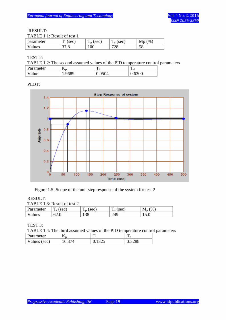
RESULT:
TABLE 1.1: Result of test 1
parameter Tr (sec) Tp (sec) Ts (sec) Mp (%)
Values 37.8 100 728 58
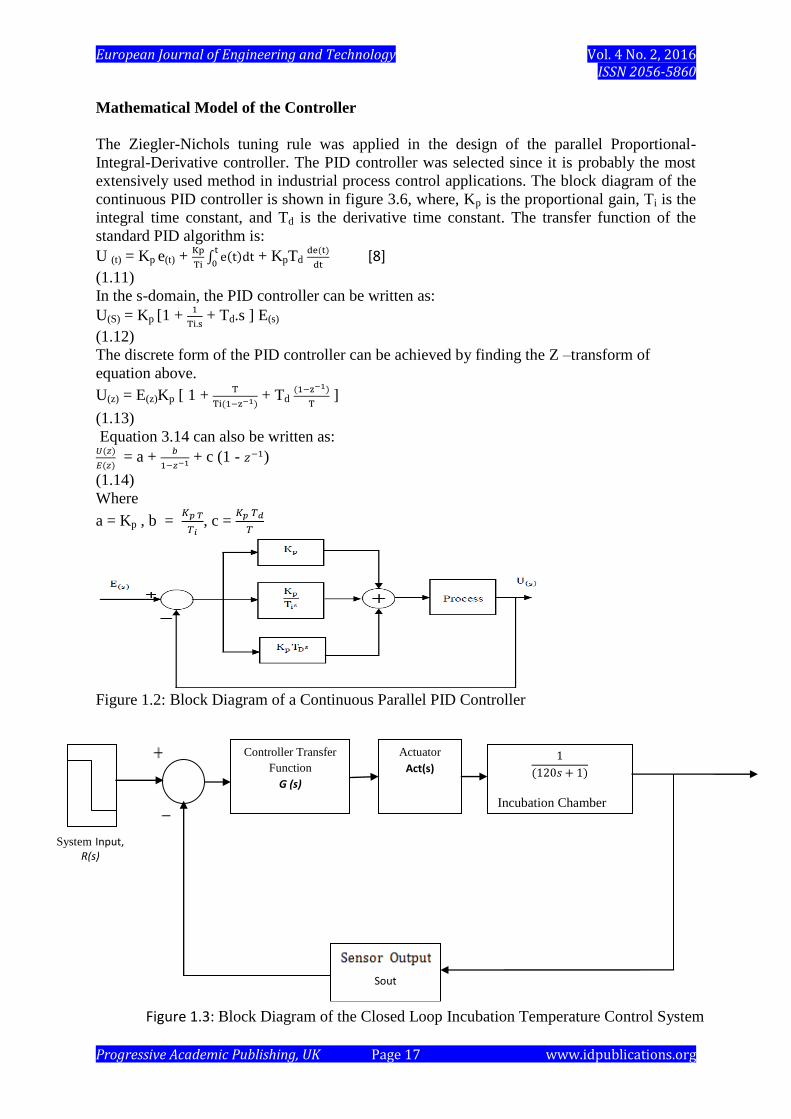
TEST 2:
TABLE 1.2: The second assumed values of the PID temperature control parameters
Parameter Kp Ti Td
Value 1.9689 0.0504 0.6300
PLOT:
RESULT:
TABLE 1.3: Result of test 2
Parameter Tr (sec) Tp (sec) Ts (sec) Mp (%)
Values 62.0 138 249 15.0
TEST 3:
TABLE 1.4: The third assumed values of the PID temperature control parameters
Parameter Kp Ti Td
Values (sec) 16.374 0.1325 3.3288
Figure 1.5: Scope of the unit step response of the system for test 2

European Journal of Engineering and Technology Vol. 4 No. 2, 2016 ISSN 2056-5860
Progressive Academic Publishing, UK Page 20 www.idpublications.org
PLOT:
RESULT:
TABLE 1.5: Result of test 3
Parameter Tr (sec) Tp (sec) Ts (sec) Mp (%)
Values 16.8 ---- 30.0 ----
RESULT ANALYSIS
Using Matlab/Simulink toolbox, various parameters were tested and the best parameters were
used for PID implementation on the microcontroller. The results showed the system
responses to a step input with varying PID temperature control parameters based on Zeigler-
Nichols tuning method. It can be inferred from the results that the optimal set of parameters
that gave a more desirable transient response in terms of short rise time, low overshoot, short
settling time, low steady state error were gotten from the results of test 3 where:
Proportional gain, Kp = 16.374,
Integral time, Ti = 0.1325,
Derivative time, Td = 3.3288.
Hence, a PID algorithm implemented on a microcontroller using the set of parameters
obtained from test 3 will exhibit a better control performance to changing temperature
conditions in the incubation system.
CONCLUSION
This work develops a model, design and simulation of a temperature control of a smart egg
incubator system for various types of egg. Keypad was incorporated in the system which
allows the operator to key in the temperature value within the range of 35- 40oC, depending
on the type of egg to be incubated. Temperature was measured using LM35 Ic and its value
displayed at the LCD. 4-relays were used for the switching of the incandescent lamps, fan
motor and DC motor. Weight sensor was used to monitor the weight of egg in the incubator.
Figure 1.6: Scope of the unit step response of the system for test 3

European Journal of Engineering and Technology Vol. 4 No. 2, 2016 ISSN 2056-5860
Progressive Academic Publishing, UK Page 21 www.idpublications.org
Monitoring of weight becomes necessary in order to ensure that the embryo is properly
developing.
The PID controller implemented in microcontroller control the temperature of the system.
Simulation was carried out by varying the temperature parameters of the PID controller in
order to obtain set of parameters that when implemented in microcontroller ensures
temperature stability at the incubator.
REFERENCES
[1] Sansomboonsuk. S., 2011 “An Automatic Incubator,” J. Energy Research, vol. 2, no. 2,
pp. 51-56,
[2] Jeffrey J.S, Martin G.P. and Fanguy R.C 2008, “The incubation of ratite eggs,” A & M
University System, Texas.
[3] Anthony Obidiwe , Chukwugoziem Ihekweaba , Patrick Aguodoh . 2014
Computer Engineering Dept. Michael Okpara University of Agriculture, Umudike, Abia
State Nigeria. “Design and Implementation of a Microcontroller Based Egg Incubator with
Digital Temperature read out” International Journal of Advanced Research in Electrical,
Electronics and Instrumentation Engineering (An ISO 3297: 2007 Certified Organization)
Vol. 3, Issue 2.
[4] Radhakrishnan .K1 , Noble Jose
2, Sanjay S G
3, Thomas Cherian
3, Vishnu K R
4., 2014
Design and Implementation of a Fully Automated Egg Incubator
Professor, Dept. of EEE, Mar Athanasius College of Engineering, Kothamangalam1
UG Student, Dept. of EEE, Mar Athanasius College of Engineering, Kothamangalam, India
[ 2,3,4,5]
[5]Berry, J.G., 2005 Artificial Incubation. Oklahoma Cooperative Extension Service. In:
http://pods.dasnr.okstate.edu/docushare/dsweb/Get/Document-2104/F-8100web.pdf Accessed
in 17/07/05
[6] Deeming, C., 2005. Incubation technology in the 21st century: Are we close to replacing
the hatchery manager? Poultry International. Volume 44, Number 7
[7] Martin, R. D., 2005. The development of Artificial Incubation of Eggs. February 2002.
In: http://www.bernalpublishing.com/poultry/essays/essay01.shtml Accessed in 17/07/05
[email protected] . Artificial incubation of poultry eggs, Accessed in May, 2015
[8] Okpagu P.E and Mbachu C.B, Nwosu A.W, 2015. An Improved Temperature Control
System for Neonatal Incubator . “European Journal of Engineering and Technology”.
Volume 3. No 6, 2015.