Development and Modeling of Multi-phase Polymeric Origami ...€¦ · explicit dynamics solver...
16
TSpace Research Repository tspace.library.utoronto.ca Development and Modeling of Multi-phase Polymeric Origami Inspired Architecture by Using Pre-molded Geometrical Features Mohamed Ali E Kshad and Hani E Naguib Version Post-print/accepted manuscript Citation (published version) Kshad, M. A. E., & Naguib, H. E. (2016). Development and modeling of multi-phase polymeric origami inspired architecture by using pre- molded geometrical features. Smart Materials and Structures, 26(2), 025012. Publisher’s Statement This is an author-created, un-copyedited version of an article accepted for publication/published in Smart Materials and Structures. IOP Publishing Ltd is not responsible for any errors or omissions in this version of the manuscript or any version derived from it. The Version of Record is available online at 10.1088/1361-665X/26/2/025012 How to cite TSpace items Always cite the published version, so the author(s) will receive recognition through services that track citation counts, e.g. Scopus. If you need to cite the page number of the author manuscript from TSpace because you cannot access the published version, then cite the TSpace version in addition to the published version using the permanent URI (handle) found on the record page. This article was made openly accessible by U of T Faculty. Please tell us how this access benefits you. Your story matters.
Transcript of Development and Modeling of Multi-phase Polymeric Origami ...€¦ · explicit dynamics solver...

TSpace Research Repository tspace.library.utoronto.ca
Development and Modeling of Multi-phase Polymeric Origami Inspired Architecture by
Using Pre-molded Geometrical Features
Mohamed Ali E Kshad and Hani E Naguib
Version Post-print/accepted manuscript
Citation
(published version)
Kshad, M. A. E., & Naguib, H. E. (2016). Development and modeling
of multi-phase polymeric origami inspired architecture by using pre-molded geometrical features. Smart Materials and Structures, 26(2),
025012.
Publisher’s Statement This is an author-created, un-copyedited version of an article
accepted for publication/published in Smart Materials and Structures. IOP Publishing Ltd is not responsible for any errors or
omissions in this version of the manuscript or any version derived from it. The Version of Record is available online at
10.1088/1361-665X/26/2/025012
How to cite TSpace items
Always cite the published version, so the author(s) will receive recognition through services that track
citation counts, e.g. Scopus. If you need to cite the page number of the author manuscript from TSpace because you cannot access the published version, then cite the TSpace version in addition to the published
version using the permanent URI (handle) found on the record page.
This article was made openly accessible by U of T Faculty.
Please tell us how this access benefits you. Your story matters.

1
Development and Modeling of Multi-phase Polymeric Origami Inspired
Architecture by Using Pre-molded Geometrical Features
Mohamed Ali E Kshad1 and Hani E Naguib1,2,3 1
Department of Mechanical and Industrial Engineering, University of Toronto, Canada 2
Department of Materials Science and Engineering, University of Toronto, Canada 3
Institute of Biomaterials and Biomedical Engineering, University of Toronto, Canada E-mail: [email protected]; phone 4169787054; sapl.mie.utoronto.ca
ABSTRACT
Using Origami folded cores in sandwich structures for lightweight applications has attracted attention
in different engineering applications, especially in the applications where the stiffness to weight ratio
is a critical design parameter. Recently, common sandwich cores such as honey-comb and foamed
cores have been replaced with origami core panels due to their way of force redistribution and energy
absorption; these unique characteristics give origami cores high stiffness to weight ratio and high
bending and twisting resistance. This paper presents the results of experimental investigations of the
effect of base material on the mechanical properties and the impact resistance of Miura-Origami
sandwich cores; then, the experimental results are compared with FEA simulation results. The
materials used in the study for the origami cores were polymer blends composed of polylactic acid
(PLA) and thermoplastic polyurethane (TPU). PLA/TPU blend compositions are (100/0, 80/20, 65/35,
50/50, 20/80, and 0/100) as a weight percentage. The geometrical parameters of the unit cell, base
material thickness, and the panel thickness were considered to be constants in this study. The study
shows the behavior of the origami cores under impact test and the energy absorbed by the origami
folded cores. It was found that 20/80 PLA/TPU blend demonstrated the highest specific energy
absorption efficiency both in quasi-static compression and impact tests. Fractured Origami structures
were observed to fail at folded edges (creases lines), while the facets exhibit rigid body rotations. The
FEM simulation showed a consistency in the impact behavior of the origami cores, and the directional
deformational of origami core units which explain the ability of the structure to redistribute the
applied force and absorb energy. In this work the origami folded core features were molded directly
from the blended material.
Keywords: Origami, Sandwich, Folded, Cores, Polymers, Compression, Impact, Modeling, Stress.

2
1. INTRODUCTION
Sandwich core structures, usually composed of a thick lightweight core covered by two thin and stiff
faces [1], are widely used for energy-absorption applications. Conventional sandwich core structures
with honey-comb, foam, and ribbed stiffened cores have been used for such applications for many
years. The mechanical performance of honeycomb cores deteriorate over time due to the moisture
accumulation inside the sealed cells [1,2]. Recently, many new types of core structures have evolved
for lightweight structures, such as truss core panels, open and closed cell foamed cores, functionally
graded foams, and folded cores [3]. The global mechanical properties of two dimensional sheets can
be enhanced by introducing a local texture to the material sheet [4]. The new manufacturing methods
have allowed folded cores to be more promising for such applications [3]. Origami is the art of paper
folding in which complex spatial objects can be created from a flat sheet [5]. It has an intrinsic source
of inspiration for innovation of mechanical metamaterials, for which the material properties are
defined more by the geometry and the way the materials are arranged than from the properties of its
parent materials [5,6]. Rigid origami, in which the faces between the crease lines remain rigid and
only the creases deform during the folding process, has an advantage over other classes of origami
patterns that require faces bending and crumpling. During the load application, only crease lines
deform while the faces have rigid body rotation [7]. Most previous studies have focused on periodic
origami patterns; however, the non-periodic origami patterns have not yet received attention because
of their complexity in theoretical modeling [7,8]. The main idea behind origami folded cores is their
ability to absorb impact and compression energy through deformation of tessellation patterns, which
is due to the collapse mechanism of the tessellation faces along folding lines without causing material
rupture [4]. The origami pattern of origami tessellation is periodic in the planar direction, and the unit
cell geometry, which consists of four identical faces joined through the crease lines, is characterized
by the faces’ dimensions and folding angles. The mechanical properties of the origami cores are
characterized in a partly folded state [7,9]. The geometrical mechanics and characteristics of origami
patterns have been studied by many researchers [7,9]. Furthermore, many research studies have
provided mathematical and analytical models for the origami folded cores, including computer
simulations and finite element analysis [5,7]. Extensive work has been carried out in the progress and
development of folded cores in Tupolev State Technical University [10–14], in which different folded
cores with different folding patterns have been investigated for mechanical properties and engineering
applications [3]. Alekseev [15] has presented a simulation of geometrical parameters of both regular
and irregular folded cores using CAD systems for designing the structure. A theoretical and
experimental study to determine the characteristics of Z-Crimp cores has been introduced by
Paimushin, et al. [15], while Shabalin et al. [16] provided a simulation of Z-Crimp shaping using the
ANSYS finite element package. The effect of the geometrical parameters of Z-Crimp origami pattern
on strength under transverse compression and longitudinal shear at the same volumetric density made
of different materials has been investigated by Dvoeglazov et al. [17]; the authors outlined valuable

3
recommendations for the selection of structural parameters concerning origami structures for high
strength. Tolman et al. [18] have introduced a three-stage strategy for material selection of Miura-
origami structure. A numerical investigation of Miura-origami cores under quasi-static loads has been
done by Zhou et al. [1], in which they found that the performance in compression and shear of the
models with curved lines higher than the flat faced origami cores.
The objective of this study is to introduce an experimental investigation supported by finite element
evaluation of the effect of base material on the mechanical properties and the impact resistance of
Miura-Origami cores. The origami structures were geometrically molded at the fabrication stage
without post folding of flat sheets. The materials used in the study for the origami cores are polymer
blends composed of polylactic acid (PLA) and thermoplastic polyurethane (TPU). PLA/TPU blend
compositions are (100/0, 80/20, 65/35, 50/50, 20/80, and 0/100) as a weight percentage. The origami
pattern is periodic in the planar direction, and the unit cell geometry is characterized by four identical
faces and folding angles. The mechanical properties of the origami cores are characterized in a partly
folded state. The geometrical parameters of the unit cell, base material thickness, and the panel
thickness are considered constants in this study. The study presents the results of the compression test,
the impact resistance, and the energy absorbed by the folded cores in the impact test. The finite
element simulation has been conducted by modeling the origami structure as a sandwich, using the
explicit dynamics solver provided by ANSYS software, the shell element type used to represent the
origami cores and the sandwich faces, the impactor modeled as a rigid part.
2. EXPEREMENTAL WORK
2.1 Materials Processing
The materials used to produce polymeric blends for origami samples are Poly-Lactic Acid (PLA)
(3052D) obtained from Natureworks LLC (USA), the reported melting temperature range of PLA is
145 – 160 °C and the density is 1.24 g/cm3. PLA is a bio-based polymer has advantage mechanical
properties, low energy processability, and it is also bio-degradable [19]. The main drawbacks of PLA
are its high brittleness, low impact strength and toughness [19]. There have been a number of studies
to improve these limitations; one of the effective ways is to form PLA blends with other polymers like
Thermoplastic polyurethane (TPU) which features by strength, ductility, impact resistance and
toughness [19]. TPU is grade (55D) obtained from Lubrizol Engineering Polymers (USA). The
reported melting temperature of TPU is 181 °C and the density is 1.16 g/cm3. Both polymers are in
pellet form, the weight percentage of PLA/TPU blend compositions used were 80/20, 65/35, 50/50,
20/80, in addition to the neat PLA and TPU. A twin screw micro-compounder (DSM; Geleen,
Netherlands) (MICRO15) was used to fabricate the material blends, by melting and mixing the pellets
at a temperature range of (185 – 195 C) with the screw speed of 30 rpm for 10 min. Then, the blends
were extruded and pelletized.

4
2.2 Fabrication of Origami Structures
Three samples from each batch have been fabricated using compression molding. The mold was
designed in three parts, allowing the samples to be removed easily after molding (see figure 1- a). The
molding temperature was kept at 205 C and pressure of 3 Tons. Silicon based mold release spray was
used to help releasing the samples from the mold. During the first samples preparation, a lot of
bubbles were observed in the produced samples, so the mold has been sealed using fiber reinforced
rubber to prevent bubbles occurrence and to avoid polymer leak. The pelletized material blends were
melted and compressed between the upper and lower jaws of the mold and then held at 3 Tons for 10
minutes to allow uniform distribution of the material. Tensile specimens were also prepared for tensile
test from each blend according to ASTM 638.
Figure 1. a) Multi-stage compression mold used to fabricate origami cores
b) The geometrical parameters of fabricated origami cors
2.3 Miura Origami Unit Cell and Core Configuration:
Origami structure consists of a periodic tessellation of unit cells, which are made of thin-walled faces
connected at fold lines; it gains its unconventional mechanical properties from the interaction between
the fold lines and the deformation of the interlaying faces [4]. Periodic origami geometry is defined by
a repetitive unit cell, characterized by specific geometric parameters. Figure 1-b shows the panel of
Miura-origami in partially folded state. The unit cell can be characterized by a specified set of its
face’s parallelogram independent parameters and the folding angle. The pattern parameters can be
calculated using equations (1-4) [8,10]:
𝐻 = 𝑎. 𝑠𝑖𝑛 𝜃 𝑠𝑖𝑛 𝛾, (1)
𝑆 = 𝑏. 𝑐𝑜𝑠 𝜃 𝑡𝑎𝑛𝛾
√1+𝑐𝑜𝑠2 𝜃.𝑡𝑎𝑛2𝛾, (2)
𝐿 = 𝑎. √1 − 𝑠𝑖𝑛2𝜃𝑠𝑖𝑛2𝛾, (3)
𝑉 = 𝑏.1
√1+𝑐𝑜𝑠2𝜃.𝑡𝑎𝑛2𝛾 (4)

5
where H, a and b, , , S, L, and V are the height of the origami panel, the face dimensions of the unit
cell, parallelogram angle, fold angle, surface area, unit cell height, and the overall volume,
respectively [8,10]. The folded core panel is defined by the number of tessellations, which is defined
by the size of the core panel (W, L, H) where W, L, and H are the width, length, and height of the core
panel, respectively. The geometrical parameters used to generate the origami core samples are (a = b
= 24 mm, W = L = 120 mm, H = 20 mm, = = 45 , and the thickness is 1.5 mm).
The volumetric density of the origami panel can be calculated using equation (5),
𝜌𝑐 =𝑡∗𝑆
𝑉𝜌𝑚 (5)
where c is core volumetric density, t is parent material thickness, and m is parent material density
[8,10]. Table 1 shows the values of blended materials densities and the origami core volumetric
densities made from PLA/TPU blends.
Table 1. Material blends density and origami volumetric density
Material Blends (PLA/TPU)
w % Material Blends Density (g/cm3) Volumetric Origami Density (g/cm3)
Neat PLA 1.24 0.161
80/20 1.220 0.158
65/35 1.213 0.157
50/50 1.198 0.155
20/80 1.175 0.152
Neat TPU 1.16 0.150
2.4 Compression Test
A compression test, which measures the capacity of origami cores to withstand compressive loads,
was conducted to determine the strength of origami cores which. The origami core samples were
tested using a compression testing general machine. Two thick steel plates have been assembled with
the testing machine allowing the load to be uniformly distributed on the origami panel structure. The
test was consistent with ASTM D1621/94 standard with 5 mm/min stroke. Three specimens were
tested for each origami structure. Each sample has 9 periodical cells (see figure 1-b) with a cell size of
(40*40 mm). A tensile test of base materials was conducted according to ASTM D638 standard to
determine the tensile modulus.
2.5 Impact Test
Impact test conducted using a custom setup which was designed to measure the force and the energy
transferred by the tested sample due to impact event. The origami core is sandwiched between two flat
polycarbonate sheets with a thickness of (7 mm) (figure 2-a). Then the sandwich samples were placed
on the flat disk of the test stand which is connected to a quartz based dynamic load sensor (Dytran,
1060V) see figure 2-b. By adjusting the dropped weight we vary the impact energy; in this study the
impact weight is 1.104 kg while the drop height is 66.5 cm. The test was conducted based on ASTM
D7136/D7136M standard. Force and time were recorded during the impact event.

6
Figure 2. a) Origami Sandwich core sample, b) Sandwich sample placed in the test stand
3. SIMULATION AND ANALYSIS
3.1 Compression Simulation
In order to simulate the compression tests, the Static Structural analyzer provided by ANSYS was
used. In the simulation, the origami core placed on a thick steel plate, and it was represented by shell
elements, and the thick plate was represented by solid elements. Frictions-less contacts between the
origami core and the plate have been defined, and the lower side of the plate was constrained by fixed
boundary condition. A compression strain of 10.1 mm was applied as a compression load. Figure 3-a
shows the meshed geometry of the compression model.
3.2 Impact event simulation
For impact event simulation, the explicit dynamics solver provided by ANSYS was used: the origami
core and sandwich faces were represented by shell elements, while the impactor was represented by
solid elements. Fixed boundary condition was used in the bottom side of the lower plate, and free
directional constraints were used for the impactor in the load direction. Frictionless contact has been
defined between the impactor and the upper side of the upper plate of the sandwich, and bonded
contacts between the sandwich faces and the origami core have been defined. Figure 3-b shows the
meshed geometry of the origami sandwich structure. The mass of the impactor used to be 1.1014 kg
and the contact velocity was 3571.137 mm s-1. The impact event end time was 0.002 s.
Figure 3. The meshed geometry of the origami a) compression simulation, b) impact simulation

7
4. RESULTS AND DISCUSSION
4.1 Compression Test Results
The compression test of the origami cores shows that with the increase of the soft material (TPU), the
origami core strength decreases while the origami core samples with high content of PLA have the
higher strength. In contrast, samples with high percentages of TPU have higher compressive strains.
Samples with high strength values experienced fracture along the crease lines, while high TPU
content core samples were able to recover, but at the expense of the strength. Figure 4 shows the
stress-strain behavior of the origami cores, and figure 5 shows the changing in elasticity modulus and
the strength of the origami cores, respectively. Figure 6 compares the compressive deflection behavior
at maximum stress and the maximum stress of the origami cores. The toughness of the origami cores
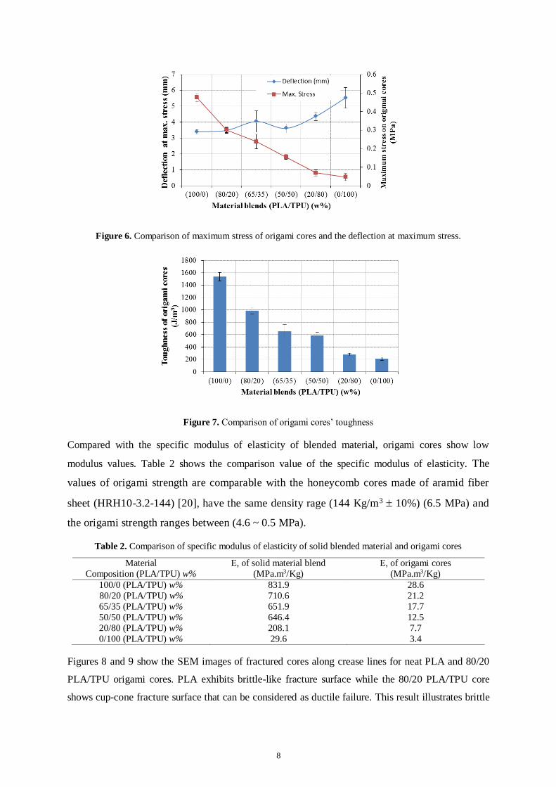
illustrated in figure 7, PLA samples have the maximum values of toughness of about 1500 (J/m3), this
value keeps decreasing by the increase of TPU amount to about 600 (J/m3) for 50/50 (PLA/TPU)
sample, and to about 210 (J/m3) for the neat TPU samples. By the controlling the material blends
weight percentage; it is possible to tailor the compression stiffness and strength.
Figure 4. Compression stress-strain relation of origami core structure
Figure 5. Modulus of elasticity and strength of origami cores
8
Figure 6. Comparison of maximum stress of origami cores and the deflection at maximum stress.
Figure 7. Comparison of origami cores’ toughness
Compared with the specific modulus of elasticity of blended material, origami cores show low
modulus values. Table 2 shows the comparison value of the specific modulus of elasticity. The
values of origami strength are comparable with the honeycomb cores made of aramid fiber
sheet (HRH10-3.2-144) [20], have the same density rage (144 Kg/m3 10%) (6.5 MPa) and
the origami strength ranges between (4.6 ~ 0.5 MPa).
Table 2. Comparison of specific modulus of elasticity of solid blended material and origami cores
Material
Composition (PLA/TPU) w%
E, of solid material blend
(MPa.m3/Kg)
E, of origami cores
(MPa.m3/Kg)
100/0 (PLA/TPU) w% 831.9 28.6
80/20 (PLA/TPU) w% 710.6 21.2
65/35 (PLA/TPU) w% 651.9 17.7
50/50 (PLA/TPU) w% 646.4 12.5
20/80 (PLA/TPU) w% 208.1 7.7
0/100 (PLA/TPU) w% 29.6 3.4
Figures 8 and 9 show the SEM images of fractured cores along crease lines for neat PLA and 80/20
PLA/TPU origami cores. PLA exhibits brittle-like fracture surface while the 80/20 PLA/TPU core
shows cup-cone fracture surface that can be considered as ductile failure. This result illustrates brittle
9
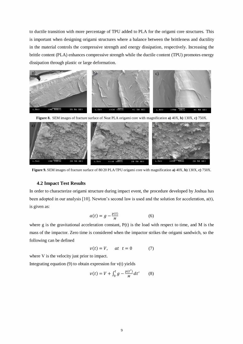
to ductile transition with more percentage of TPU added to PLA for the origami core structures. This
is important when designing origami structures where a balance between the brittleness and ductility
in the material controls the compressive strength and energy dissipation, respectively. Increasing the
brittle content (PLA) enhances compressive strength while the ductile content (TPU) promotes energy
dissipation through plastic or large deformation.
Figure 8. SEM images of fracture surface of Neat PLA origami core with magnification a) 40X, b) 130X, c) 750X.
Figure 9. SEM images of fracture surface of 80/20 PLA/TPU origami core with magnification a) 40X, b) 130X, c) 750X.
4.2 Impact Test Results
In order to characterize origami structure during impact event, the procedure developed by Joshua has
been adopted in our analysis [10]. Newton’s second law is used and the solution for acceleration, a(t),
is given as:
𝑎(𝑡) = 𝑔 −𝑝(𝑡)
𝑀 (6)
where g is the gravitational acceleration constant, P(t) is the load with respect to time, and M is the
mass of the impactor. Zero time is considered when the impactor strikes the origami sandwich, so the
following can be defined
𝑣(𝑡) = 𝑉, 𝑎𝑡 𝑡 = 0 (7)
where V is the velocity just prior to impact.
Integrating equation (9) to obtain expression for v(t) yields
𝑣(𝑡) = 𝑉 + ∫ 𝑔 −𝑝(𝑡 ′)
𝑀𝑑𝑡′𝑡
0 (8)

10
Once the previous quantities are obtained from our experimental setup, solving for the energy
transferred as a function of time gives
Γ(𝑡) = ∫ 𝑝(𝑡′) 𝑣(𝑡′)𝑡
0 𝑑𝑡′ (9)
Figure 10 shows a sample of transferred impact force by neat PLA origami sandwich structure. There
is force increase at the beginning of impact until a maximum value is reached, and then a decrease
while the origami sandwich structure bounces back the impactor. This curve represents the P(t) values
in the equations above. V is calculated from Newton’s equation of falling objects for an impactor
mass of 1.104 Kg and drop height of 66.5 cm which reveals a value of 3.571134 m/sec. Maximum
force and energy transfer is observed at high percentages of PLA which is attributed to the high
compressive resistance due to brittle nature. The 20/80 PLA/TPU blend transfers force of 1.88 KN
which is the lowest for all origami sandwich structures (see figures 11 and 12). As discussed in the
previous section, the selection of the origami material depends on the application where the different
percentages of PLA and TPU influence the amount of force and energy transfer. The reported values
in this study are for the transferred force and energy where the receiver is our primary concern. Neat
TPU provides low force transfer but it has the lowest compressive strength as noted in section 4.1.
PLA can be added to enhance compressive strength while observing the transferred force, see figure
12. For example, 65/35 PLA/TPU blend increases the force transfer from 2.19 KN for neat TPU to 2.8
KN while also increasing the compressive modulus from 0.511 MPa to 2.79 MPa. So as discussed
before, the origami structures can be designed for energy absorption while maintaining a required
strength by controlling the amounts of PLA and TPU.
Figure 10. Sample of impact force for neat PLA

11
Figure 11. Maximum transferred impact force Figure 12. Maximum impact energy transferred
When compared with conventional materials, origami cores show better impact force damping. Table
3 shows the comparison of the transferred force of (PLA/TPU) origami cores with polycarbonate and
steel sheets during the same impact event.
Table 3. Comparison of maximum impact force transferred
Material Maximum Force Transferred
(N)
100/0 (PLA/TPU) w% 3708.2
80/20 (PLA/TPU) w% 3085.4
65/35 (PLA/TPU) w% 2806.4
50/50 (PLA/TPU) w% 2584.0
20/80 (PLA/TPU) w% 1882.4
0/100 (PLA/TPU) w% 2195.8
Polycarbonate 11432.9
Steel 20852.0
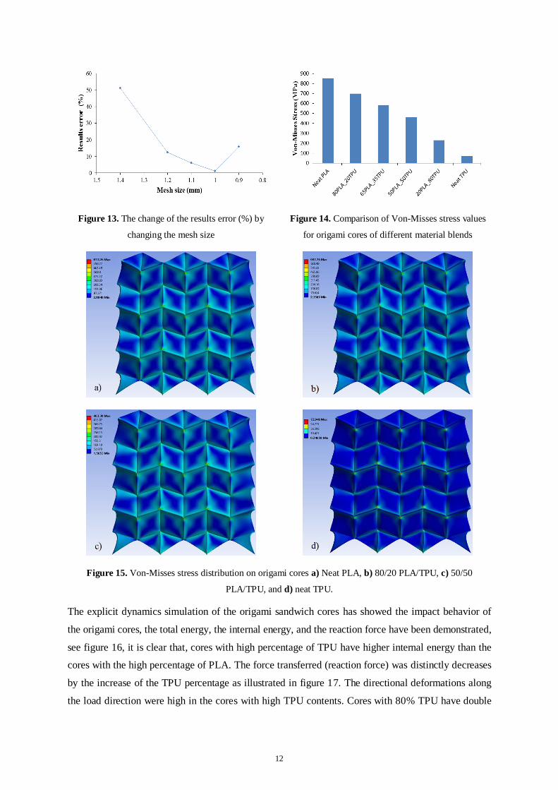
4.3 Finite Element Results
The results of the FEM were converging by the decrease of the element size from 1.4mm to 1mm and
then it started diverging (see figure 13), the number of shell elements of origami cores was 29198, and
the number of nodes was 42514. The static structural analysis of the origami cores has showed that,
the maximum Von-Misses stress was in the neat PLA cores with the value of 853.26MPa, and it keeps
decreasing by the increase of the TPU content, which has the minimum value of 72.946MPa. Figure
14 shows the comparison of maximum Von-Misses stress values, and figure 15 shows the Von-Misses
stress distribution on the origami cores of neat PLA, 80/20 PLA/TPU, 50/50 PLA/TPU, and neat
TPU. It is clear that the high values of stresses occur in the crease lines, and they become the stress
concentration zones, while the faces are the low stress areas, as a result the facture always expected to
happen along the crease lines.
12
Figure 13. The change of the results error (%) by
changing the mesh size
Figure 14. Comparison of Von-Misses stress values
for origami cores of different material blends
Figure 15. Von-Misses stress distribution on origami cores a) Neat PLA, b) 80/20 PLA/TPU, c) 50/50
PLA/TPU, and d) neat TPU.
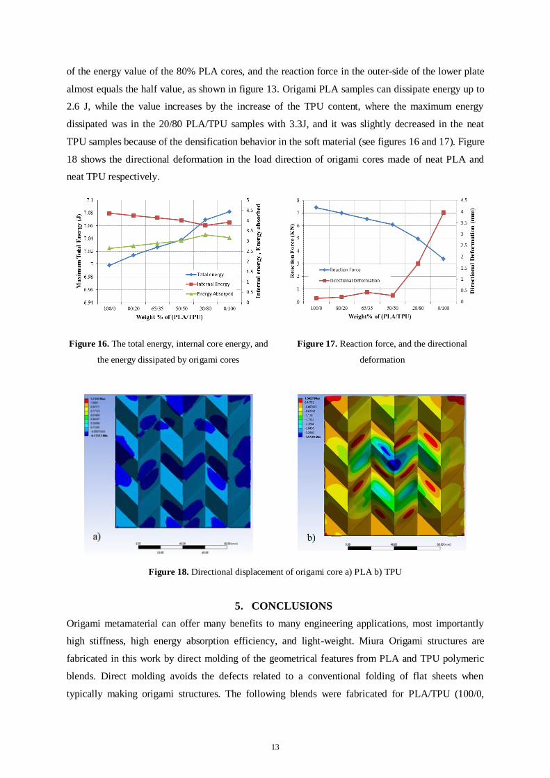
The explicit dynamics simulation of the origami sandwich cores has showed the impact behavior of
the origami cores, the total energy, the internal energy, and the reaction force have been demonstrated,
see figure 16, it is clear that, cores with high percentage of TPU have higher internal energy than the
cores with the high percentage of PLA. The force transferred (reaction force) was distinctly decreases
by the increase of the TPU percentage as illustrated in figure 17. The directional deformations along
the load direction were high in the cores with high TPU contents. Cores with 80% TPU have double
13
of the energy value of the 80% PLA cores, and the reaction force in the outer-side of the lower plate
almost equals the half value, as shown in figure 13. Origami PLA samples can dissipate energy up to
2.6 J, while the value increases by the increase of the TPU content, where the maximum energy
dissipated was in the 20/80 PLA/TPU samples with 3.3J, and it was slightly decreased in the neat
TPU samples because of the densification behavior in the soft material (see figures 16 and 17). Figure
18 shows the directional deformation in the load direction of origami cores made of neat PLA and
neat TPU respectively.
Figure 16. The total energy, internal core energy, and
the energy dissipated by origami cores
Figure 17. Reaction force, and the directional
deformation
Figure 18. Directional displacement of origami core a) PLA b) TPU
5. CONCLUSIONS
Origami metamaterial can offer many benefits to many engineering applications, most importantly
high stiffness, high energy absorption efficiency, and light-weight. Miura Origami structures are
fabricated in this work by direct molding of the geometrical features from PLA and TPU polymeric
blends. Direct molding avoids the defects related to a conventional folding of flat sheets when
typically making origami structures. The following blends were fabricated for PLA/TPU (100/0,

14
80/20, 65/35, 50/50, 20/80, and 0/100). Those different percentages of PLA and TPU reflect the
increase in compressive strength or energy transfer respectively. The balance between PLA and TPU
will depend on the intended application. PLA origami structure offers maximum force transfer of
686.1 N and highest compressive modulus of 4.6 MPa. The high compressive modulus of PLA
resulted in fracture at crease lines. The high modulus of PLA origami structure can be reduced to 2.79
MPa by adding 35% of TPU which offers more elasticity and avoid failure at high compressive
strains. The addition of 35% TPU also reduces the force transfer to 2.8 KN. The finite element
modeling has been conducted using static structural for compression test and explicit dynamics for
impact event. The compression results showed that the crease lines are the stress concentration zones,
and it is subjected to fracture in the blends with high elastic modulus while the faces carry low-stress
values. The FEA results also demonstrated that origami made structure made of a high percentage of
80% TPU has the highest values of energy absorption (up to 3.3 J), with directional deformation
exceeded (1.6 mm), and it has the lowest Von-Misses stress in compression. This work provided
numerical quantification of the compromise between compressive strength and energy transfer which
can be used to design origami structure with target values for both.
ACKNOWLDGEMENTS
The authors would like to acknowledge the following agencies for financial support: The Natural
Science and Engineering Research Council (NSERC) of Canada, the Canada Research Chair
Program, the Libyan Ministry of Higher Education and scientific research, Tripoli. And also the
authors would like to extend their acknowledgements to Daniel Grozea, from Material Department for
his technical support.
REFERENCES
[1] Zhou X, Wang H and You Z 2014 Mechanical properties of Miura-based folded cores under quasi-static loads Thin-Walled Struct. 82 296–310
[2] Herrmann A S, Zahlen P C and Zuardy I 2005 Sandwich Structures Technology in Commerical Aviation: Present Applications and Future Trends Sandw. Struct. Adv. with Sandw. Struct. Mater. 7 13–26
[3] Sab K and Lebée A 2010 Transverse shear stiffness of a chevron folded core used in sandwich
construction Int. J. Solids Struct. 47 2620–9 [4] Schenk M 2011 Folded Shell Structures (PhD. thesis, Clare College University of Cambridge) [5] Wonoto N, Baerlecken D, Gentry R and Swarts M 2013 Parametric design and structural analysis
of deployable origami tessellation Comput. Aided. Des. Appl. 10 939–51 [6] Eidini M and Paulino G H 2015 Unraveling metamaterial properties in zigzag-base folded sheets
Sci. Adv. 1 e1500224–e1500224 [7] Lv C, Krishnaraju D, Konjevod G, Yu H and Jiang H 2014 Origami based Mechanical
Metamaterials. Sci. Rep. 4 5979 [8] Schenk M and Guest S D 2011 Origami Folding: A Structural Engineering Approach Origami 5
Fifth Int. Meet. Origami Sci. Math. Educ. 1–16 [9] Schenk M and Guest S D 2013 Geometry of Miura-folded metamaterials Proc. Natl. Acad. Sci.
110 3276–81 [10] Zakirov I I 2013 Study of Creasing Parameters at Shaping of Folded Cores in Sandwich Panels
56 191–3

15
[11] Zakirov I M, Alekseev K A, Kayumov R A and Gainutdinov I R 2009 Some possible techniques for improving the strength characteristics of folded cores from sheet composite materials Russ. Aeronaut. 52 347–50
[12] Alekseev K a., Zakirov I M and Karimova G G 2011 Geometrical model of creasing roll for
manufacturing line of the wedge-shaped folded cores production Russ. Aeronaut. (Iz VUZ) 54 104–7
[13] Kayumov R a., Zakirov I M, Alekseev K P, Alekseev K a. and Zinnurov R a. 2007 Determination of load-carrying capacity in panels with chevron-type cores Russ. Aeronaut. (Iz VUZ) 50 357–61
[14] Khaliulin V I and Inkin V A 2013 Calculation of process variables at composite Z-crimp shaping using the folding method Russ. Aeronaut. (Iz VUZ) 55 417–23
[15] Paimushin V N, Zakirov I M and Karpikov Y A 2013 Theoretical and experimental technique of
determining the mechanical characteristics of folded structure filler in the form of Z-crimp (shear of a filler in cross-sectional planes) Russ. Aeronaut. (Iz VUZ) 56 234–46
[16] Shabalin L P, Sidorov I N and Khaliulin V I 2010 Simulation of Z -Crimp Shaping with the Use of the ANSYS Finite Element Software 53 339–44
[17] Dvoeglazov I V and Khaliulin V I 2013 A Study of Z-Crimp Structural Parameters Impact on Strength under Transverse Compression and Longitudinal Shear Russ. Aeronaut. 56 15–21
[18] Tolman S S, Delimont I L, Howell L L and Fullwood D T 2014 Material selection for elastic
energy absorption in origami-inspired compliant corrugations Smart Mater. Struct. 23 094010 [19] Jie Ren 2013 Biodegradable Poly lactic acid Synthesis, Modification, Processing and
Applications vol 53 (Shanghai, China: Springer) [20] HexWeb 2015 ‘HexWeb ® HRH-10,’ HexWeb ‘HexWeb® Nonmetallic Flex-Core’, [Online]. Available: http://hexcel.com/Resources/DataSheets/Honeycomb-Data-Sheets/HRH_10_eu.pdf
(Accessed: 27 October 2016)