Development and microstructure characterization of single ...
31
University of Birmingham Development and microstructure characterization of single and duplex nitriding of UNS S31803 duplex stainless steel Tschiptschin, A. P.; Varela, L. B.; Pinedo, C. E.; Li, Xiao-Ying; Dong, Hanshan DOI: 10.1016/j.surfcoat.2017.08.018 License: Creative Commons: Attribution-NonCommercial-NoDerivs (CC BY-NC-ND) Document Version Peer reviewed version Citation for published version (Harvard): Tschiptschin, AP, Varela, LB, Pinedo, CE, Li, X-Y & Dong, H 2017, 'Development and microstructure characterization of single and duplex nitriding of UNS S31803 duplex stainless steel', Surface and Coatings Technology, vol. 327, pp. 83-92. https://doi.org/10.1016/j.surfcoat.2017.08.018 Link to publication on Research at Birmingham portal General rights Unless a licence is specified above, all rights (including copyright and moral rights) in this document are retained by the authors and/or the copyright holders. The express permission of the copyright holder must be obtained for any use of this material other than for purposes permitted by law. • Users may freely distribute the URL that is used to identify this publication. • Users may download and/or print one copy of the publication from the University of Birmingham research portal for the purpose of private study or non-commercial research. • User may use extracts from the document in line with the concept of ‘fair dealing’ under the Copyright, Designs and Patents Act 1988 (?) • Users may not further distribute the material nor use it for the purposes of commercial gain. Where a licence is displayed above, please note the terms and conditions of the licence govern your use of this document. When citing, please reference the published version. Take down policy While the University of Birmingham exercises care and attention in making items available there are rare occasions when an item has been uploaded in error or has been deemed to be commercially or otherwise sensitive. If you believe that this is the case for this document, please contact [email protected] providing details and we will remove access to the work immediately and investigate. Download date: 18. Feb. 2022
Transcript of Development and microstructure characterization of single ...
University of Birmingham
Development and microstructure characterization ofsingle and duplex nitriding of UNS S31803 duplexstainless steelTschiptschin, A. P.; Varela, L. B.; Pinedo, C. E.; Li, Xiao-Ying; Dong, Hanshan
DOI:10.1016/j.surfcoat.2017.08.018
License:Creative Commons: Attribution-NonCommercial-NoDerivs (CC BY-NC-ND)
Document VersionPeer reviewed version
Citation for published version (Harvard):Tschiptschin, AP, Varela, LB, Pinedo, CE, Li, X-Y & Dong, H 2017, 'Development and microstructurecharacterization of single and duplex nitriding of UNS S31803 duplex stainless steel', Surface and CoatingsTechnology, vol. 327, pp. 83-92. https://doi.org/10.1016/j.surfcoat.2017.08.018
Link to publication on Research at Birmingham portal
General rightsUnless a licence is specified above, all rights (including copyright and moral rights) in this document are retained by the authors and/or thecopyright holders. The express permission of the copyright holder must be obtained for any use of this material other than for purposespermitted by law.
•Users may freely distribute the URL that is used to identify this publication.•Users may download and/or print one copy of the publication from the University of Birmingham research portal for the purpose of privatestudy or non-commercial research.•User may use extracts from the document in line with the concept of ‘fair dealing’ under the Copyright, Designs and Patents Act 1988 (?)•Users may not further distribute the material nor use it for the purposes of commercial gain.
Where a licence is displayed above, please note the terms and conditions of the licence govern your use of this document.
When citing, please reference the published version.
Take down policyWhile the University of Birmingham exercises care and attention in making items available there are rare occasions when an item has beenuploaded in error or has been deemed to be commercially or otherwise sensitive.
If you believe that this is the case for this document, please contact [email protected] providing details and we will remove access tothe work immediately and investigate.
Download date: 18. Feb. 2022
Accepted Manuscript
Development and microstructure characterization of single andduplex nitriding of UNS S31803 duplex stainless steel
A.P. Tschiptschin, L.B. Varela, C.E. Pinedo, X.Y. Li, H. Dong
PII: S0257-8972(17)30780-6DOI: doi: 10.1016/j.surfcoat.2017.08.018Reference: SCT 22579
To appear in: Surface & Coatings Technology
Received date: 26 March 2017Revised date: 25 June 2017Accepted date: 1 August 2017
Please cite this article as: A.P. Tschiptschin, L.B. Varela, C.E. Pinedo, X.Y. Li, H. Dong, Development and microstructure characterization of single and duplex nitriding of UNSS31803 duplex stainless steel, Surface & Coatings Technology (2017), doi: 10.1016/j.surfcoat.2017.08.018
This is a PDF file of an unedited manuscript that has been accepted for publication. Asa service to our customers we are providing this early version of the manuscript. Themanuscript will undergo copyediting, typesetting, and review of the resulting proof beforeit is published in its final form. Please note that during the production process errors maybe discovered which could affect the content, and all legal disclaimers that apply to thejournal pertain.
ACC
EPTE
D M
ANU
SCR
IPT
1
Development and Microstructure Characterization of Single and Duplex Nitriding of UNS
S31803 Duplex Stainless Steel
A.P. Tschiptschin1,#
, L.B.Varela1, C.E. Pinedo
2, X.Y. Li
3, H. Dong
3
1Department of Metallurgical and Materials Engineering, University of São Paulo, Av. Prof. Mello
Moraes 2463, ZIP 05508-030, São Paulo, SP, Brazil.
2Heat Tech Technology for Heat Treatment and Surface Engineering Ltd, Av. João XXIII 1160,
ZIP 08830-000, Mogi das Cruzes, SP, Brazil.
3School of Metallurgy and Materials, College of Engineering and Physical Sciences, The University
of Birmingham, Birmingham B15 2TT, UK.
# Corresponding author’s phone: +55-11-30915656 E-mail: [email protected]
Abstract
In this work, the development of a duplex nitriding (DN) surface treatment combining High
Temperature Gas Nitriding (HTGN) and Low Temperature Plasma Nitriding (LTPN) is reported.
The microstructure and hardness variation of the duplex treated steel is compared with the
properties obtained during single HTGN and single LTPN of UNS S31803 stainless steel. Single
LTPN of UNS S31803 was carried out in an Active Screen Plasma Nitriding reactor, at 400 °C for
20 h, in a 75 % N2 + 25 % H2 atmosphere. Single HTGN of UNS S31803 was carried out at 1200
°C, under a 0.1 MPa high purity N2 gas atmosphere, during 8 hours. The developed duplex nitriding
(DN) surface treatment consists of a combination of both, HTGN and LTPN treatments, carried out
in the same conditions described above.
The microstructure of the as received material was composed by ferrite and austenitic
stringers, aligned in the rolling direction. The results showed that LTPN of the UNS S31803 duplex
stainless steel promotes the formation of a duplex modulated structure composed by 2.5 μm thick,
1510 52 HV hard, expanded ferrite (αN) regions, and 3.0 μm thick, 1360 81 HV hard, expanded
austenite (γN) regions on ferrite and austenite grains, respectively. Intense coherent ε-Fe3N nitride
ACCEPTED MANUSCRIPT
ACC
EPTE
D M
ANU
SCR
IPT
2
precipitation inside expanded ferrite was observed. ε-Fe3N nitrides precipitated with an orientation
relationship [111] αN // [120] ε-Fe3N, leading to increased microhardness of the expanded ferrite
regions. After the first step of the duplex nitriding treatment (HTGN) a 550 μm thick, 330 HV hard,
nitrogen rich, fully austenitic layer formed at the surface of the specimens, by transformation of
ferrite stringers into austenite. The second nitriding step (LTPN) led to the formation of a
homogeneous expanded austenite layer, 1227 ± 78 HV on top of the thick fully austenitic layer,
formed during the first step. The duplex treatment resulted in a more homogeneous, precipitate-free,
microstructure and a better transition between the mechanical properties of the hardened outermost
layer and the softer substrate.
Keywords: Duplex stainless steel; High temperature gas nitriding; Low temperature plasma
nitriding; Duplex nitriding treatment.
1. Introduction
Duplex stainless steels (DSS) are widely used in high performance components for oil and
gas, nuclear, chemical and paper industries, due to its superior combination of strength and
corrosion resistance, compared to austenitic stainless steels [1]. However, for some applications,
where outstanding wear resistance is required, the bulk hardness is not high enough to guarantee the
best performance. In such applications, the use of surface treatments to increase surface hardness is
an important technological solution to improve the tribological performance and the components’
life performance.
Low Temperature Plasma Nitriding (LTPN) has proved to be a successful option to increase
surface hardness and wear resistance, without impairing the corrosion resistance of austenitic,
martensitic and ferritic stainless steels [2-4]. Low temperature nitriding, carried out at temperatures
lower than 430oC, can avoid nitride precipitation, leading to nitrogen supersaturation and formation
of expanded austenite, expanded ferrite or expanded martensite. Such supersaturation results in
ACCEPTED MANUSCRIPT
ACC
EPTE
D M
ANU
SCR
IPT
3
expansion of the crystal lattice and creation of very intense compressive residual stresses leading to
an increase of the surface hardness due to the formation of these expanded phases. Moreover, at low
temperature, chromium nitrides precipitation is avoided. Even if iron nitrides precipitate, chromium
depletion does not occur maintaining the corrosion properties of the steel.
LTPN of austenitic stainless steels has been discussed in literature, providing a rather well
defined nitriding mechanism, associated with the formation of S-phase or expanded austenite.
Nevertheless, published papers dealing with LTPN of duplex stainless steels are scarce in literature,
the mechanisms of surface hardening are not quite well understood and some controversy still exists
related to the formation of expanded austenite all over the nitrided case. Blawert at al. [5] described
a nitrogen promoted phase transformation of pre-existing ferrite into expanded austenite at the
surface of LTPN DSS specimens. Bielawski et al. [6] reported the formation of nitrogen-enriched
layers, containing an “expanded austenite like” layer obtained on top of the ferritic regions of the
matrix. Some years later, the same authors [7] reported the formation of expanded martensite on the
ferrite grains of the matrix. Christiansen et al. [8], instead, reported the formation of a thick layer of
expanded austenite on both ferrite and austenite grains of the matrix in a SAF 2507 superduplex
stainless steel. Chiu et al. [9] reported the formation of expanded ferrite and expanded austenite on
ferrite and austenite stringers of an UNS S31803 duplex, respectively.
Nagatsuka et al (10) discussed the formation of a nitrided case on top of ferrite grains and
concluded that S phase (expanded austenite) was uniformly formed on both austenitic and ferritic
phases, after ASPN at 450 ºC. In a previous work, Pinedo et al [11] found that the nitrided layer was
composed by a modulated structure developed on the surface of the specimen, containing expanded
austenite and expanded ferrite, with the expanded ferrite layer being thicker than the neighboring
expanded austenite layer. The expanded ferrite phase showed acicular structures crossing the layer,
suggesting that deformation bands propagated inside this phase due to intense compressive stresses
developed during nitriding [11].
ACCEPTED MANUSCRIPT
ACC
EPTE
D M
ANU
SCR
IPT
4
Literature reporting the mechanical and tribological (wear) behaviour of low temperature
nitrided of duplex stainless steel is scarce. Nagatsuka et al. [10] studied the wear behavior of low
temperature active screen plasma nitrided duplex stainless steel and concluded that wear resistance
was greater for active screen plasma nitriding than for DC plasma nitriding.
When submitted to high loading conditions, single LTPN duplex stainless steel may
prematurely fail as the thin and hard expanded austenite / expanded ferrite layers may collapse,
mainly due to substrate elastic and plastic deformations, the so called eggshell-effect [12]. Mesa et
al [13], studying the cavitation-erosion behavior duplex stainless steel developed a sequence of
nitriding treatments that resulted in a cavitation-erosion resistance 180 times greater than 304
stainless steel and 23 times greater than LTPN 304 stainless steel. The proposed duplex nitriding
treatment (HTGN+LTPN) was composed by a high temperature gas nitriding step (HTGN), carried
out in a pure nitrogen atmosphere at 1200ºC, for 8 hours, at 0.1 MPa pressure, followed by a low
temperature plasma nitriding step (LTPN) carried out at 400ºC, for 20 h at 400 Pa pressure. The
resulting duplex nitrided structure consisted of a thick layer of nitrogen rich austenite, followed by a
much thinner expanded austenite layer formed by LTPN. The increased substrate hardness granted
mechanical support to the thinner and harder expanded austenite layer, assuring greater adhesion of
the hard expanded austenite layer formed on top of the duplex stainless steel, assuring much greater
cavitation wear resistance [13].
The aim of this paper is to analyse the microstructural changes involved in single LTPN and
duplex (HTGN + LTPN) surface treatments of UNS S31803, in order to better understand the
mechanisms of the undergoing phase transformations and better control the nitriding parameters
assuring good tribological and micromechanical properties to the thermochemical treated alloy.
ACCEPTED MANUSCRIPT
ACC
EPTE
D M
ANU
SCR
IPT
5
2 Experimental
Wrought round bars of solution treated UNS S31803 duplex stainless steel were cut in 5 mm
thick slices. The analyzed chemical composition is shown in Table 1.
Table 1. Chemical composition in mass %
C Cr Ni Mo N Si P S
0.016 22.60 4.30 3.06 0.20 0.66 0.009 0.001
The specimens were fine ground and diamond polished before surface treatments. High
Temperature Gas Nitriding (HTGN) was carried out in a horizontal cylindrical chamber furnace at
1200°C in a pure N2 (99.999% purity) atmosphere, under 0.1 MPa pressure, during 8 hours. Low
Temperature Plasma Nitriding treatments (LTPN) were carried out in a Plasma Metal SA-
Luxemburg DC-pulsed plasma active plasma screen reactor at 400oC, using a gas mixture of 75%
N2+25% H2, under 400 Pa pressure and 20 hours, with a bias voltage of 320 V. The carbon steel
active screen was 1.5 m in diameter and 1.8 m high. The specimens were arranged in a circle
equidistant 30 cm from the screen walls and distant 1.3 m from its top.
The microstructure at the specimens' surface was analyzed by light optical microscopy
(LOM) and scanning electron microscopy (SEM). WDS analysis of the nitrogen content at the
surface of the HTGN layer was carried out in an Oxford spectrometer coupled to a Cambridge
Stereoscan 440 SEM, using a procedure developed by Toro et al. [14].
Wavelength dispersive analysis was carried out in an Oxford WDX600 spectrometer with
take-off angle 35°, coupled to a Cambridge Stereoscan 440 SEM equipped with LaB6 emission
source operating at 10 kV. A LiF crystal was used to analyze chromium and iron, while nitrogen
was measured by using synthetic LSM60 crystal. The setup procedure for quantitative analysis
included the following steps: electron beam stabilization monitored by repetitive measurements of
beam current in a Faraday cup and preliminary X-Ray acquisition from standards, which was used
ACCEPTED MANUSCRIPT

ACC
EPTE
D M
ANU
SCR
IPT
6
to define the peak acquisition window and the background level for each element to be analyzed.
Acquisition of X-Ray spectra of standard samples for chromium, iron and nitrogen. The set of
standards included: an austenitic High Nitrogen Stainless Steel (18 wt-% Cr - 15 wt-% Mn - 0.39
wt-% N), solution treated at 1200°C during 6 hours and water quenched; high-purity CrN (50 at.
%N) and Cr2N (33.3 at. %N) nitrides in the form of thin layers (2.5-3 µm in depth) deposited onto
carbon steel sheets by magnetron sputtering; conventional boron nitride pellets (50 at. %N), and
high-purity electrolytic chromium flakes (99.99 wt. %Cr) and electrolytic nickel flakes (99.99 wt.
%Ni). As a rule, in each experiment one of the chromium nitrides was chosen as standard and the
other chromium nitride and the austenitic steel were supposed unknown. The acquisition of data
from the steels only started when the measured nitrogen content of the “unknown” nitride was equal
to the stoichiometric value and the measured nitrogen content of the austenitic HNSS was (0.39 ±
0.02) wt. %.
The representative size of the beam-specimen interaction volume was estimated by using the
Kanaya-Okayama expression for the electron range [13], as follows:
89.0
67.167.1
0 )(000276.0
Z
EEAd c
OK
(1)
where
Eo = Energy of the incident beam in keV
Ec = Critical excitation energy in keV
= Density in kg.m-3
Z = Atomic number.
Since the specimen is basically a Fe-22 wt. %Cr-5 wt. %Ni alloy, the value Z = 0.73ZFe + 0.22ZCr
+ 0.05ZNi = 25.66 was used.
Calculating , for the analysis of nitrogen in the nitrided layer, we obtained = 1.52
m. The size of the beam-specimen interaction volume is of the order of magnitude of the thickness
ACCEPTED MANUSCRIPT
ACC
EPTE
D M
ANU
SCR
IPT
7
of both layers, expanded ferrite and expanded austenite. Consequently, WDS technique was only
used to measure the nitrogen content of the thick fully austenitic layer, obtained through HTGN.
X-Ray diffraction (XRD) was carried out in a Phillips diffractometer, using the -2 Bragg-
Brentano configuration and Cu-Kα radiation, λ = 0.15418 nm, with a scan rate of 0.02°/min, and 2θ
varying from 20 to 120°. Picard's equation aN = a+κ CN was used to estimate the nitrogen content
of high nitrogen austenite obtained after HTGN and expanded austenite obtained after LTPN, using
the average of the lattice parameters. In Picard’s equation, κ is equal to 0.00078 nm/at% N for
concentrations up to 10 at% N. These calculations do not consider the effect of compressive
residual stresses on the shift of diffraction peaks.
The crystal structures of the phases at the sample surface were also studied using an electron
back scattering diffraction TSL-EBSD instrument, interfaced with a XL30 Philips scanning electron
microscope. The diffraction patterns were collected in areas of 1.5 x 1.5 mm2.
Specimens for transmission electron microscopy (TEM) analysis were prepared in a 3D
FEG-FIB-SEM equipment to analyse the structure of the plasma nitrided layer formed on the single
active screen plasma nitrided (ASPN) specimens. TEM analysis were carried out in a JEOL JEM-
2100 transmission electron microscope.
Vickers microhardness tests were performed on a Shimadzu Microhardness HMV-2 tester
using a Vickers indenter with a 0.1 N load, for measuring the hardness of the thin expanded ferrite
and expanded austenite layers, formed after LTPN. These measurements were made on top of each
expanded phase. Microhardness measurements for obtaining the hardness variation with depth
below the nitrided surface, after HTGN, was carried out in the same HMV-2 tester, using a 1 N
load. These measurements were taken on the transverse section of polished microstructure. for
measuring hardness of ferritic-austenitic matrix and the fully austenitic layer obtained after HTGN.
ACCEPTED MANUSCRIPT
ACC
EPTE
D M
ANU
SCR
IPT
8
3 Results and Discussion
3.1 Microstructures and X-ray Characterization
As received
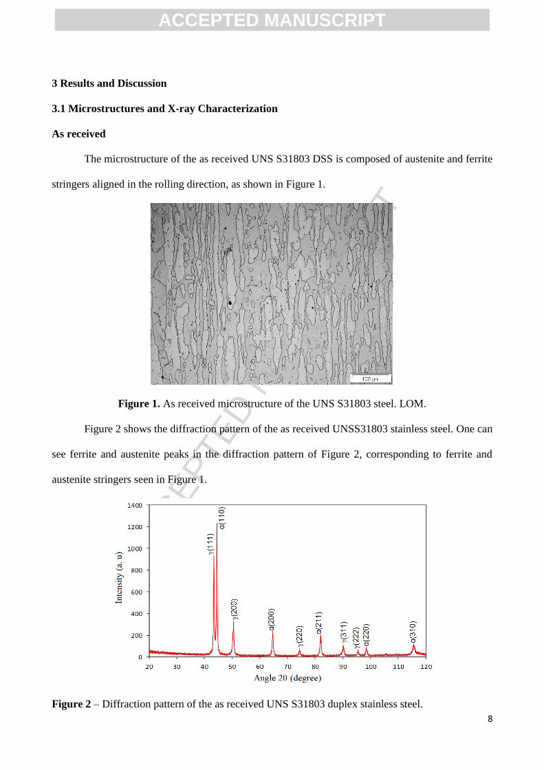
The microstructure of the as received UNS S31803 DSS is composed of austenite and ferrite
stringers aligned in the rolling direction, as shown in Figure 1.
Figure 1. As received microstructure of the UNS S31803 steel. LOM.
Figure 2 shows the diffraction pattern of the as received UNSS31803 stainless steel. One can
see ferrite and austenite peaks in the diffraction pattern of Figure 2, corresponding to ferrite and
austenite stringers seen in Figure 1.
Figure 2 – Diffraction pattern of the as received UNS S31803 duplex stainless steel.
ACCEPTED MANUSCRIPT
ACC
EPTE
D M
ANU
SCR
IPT
9
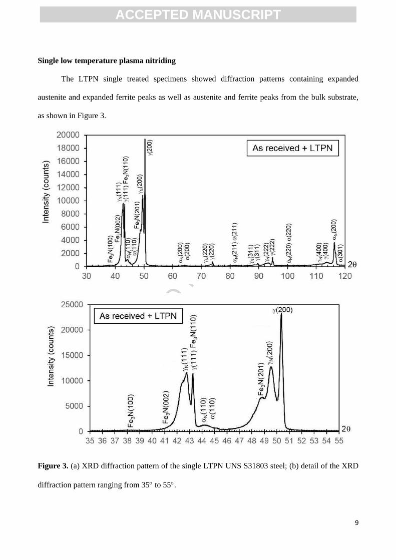
Single low temperature plasma nitriding
The LTPN single treated specimens showed diffraction patterns containing expanded
austenite and expanded ferrite peaks as well as austenite and ferrite peaks from the bulk substrate,
as shown in Figure 3.
Figure 3. (a) XRD diffraction pattern of the single LTPN UNS S31803 steel; (b) detail of the XRD
diffraction pattern ranging from 35 to 55.
ACCEPTED MANUSCRIPT
ACC
EPTE
D M
ANU
SCR
IPT
10
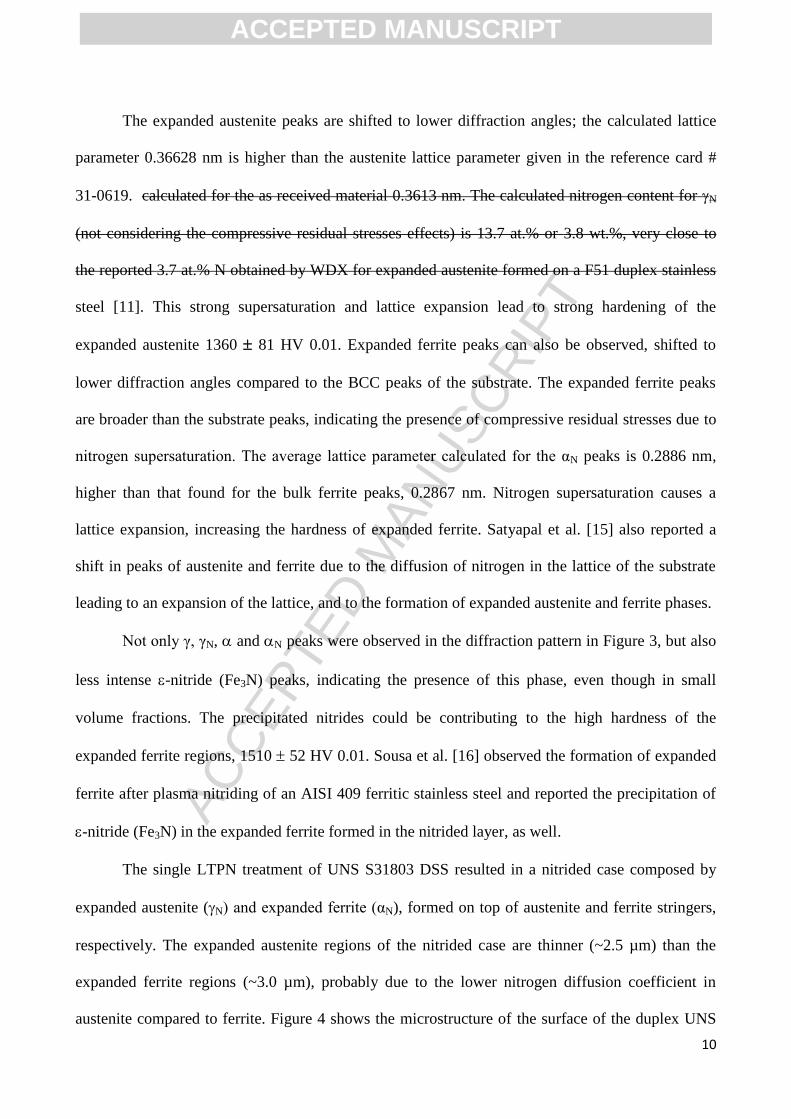
The expanded austenite peaks are shifted to lower diffraction angles; the calculated lattice
parameter 0.36628 nm is higher than the austenite lattice parameter given in the reference card #
31-0619. calculated for the as received material 0.3613 nm. The calculated nitrogen content for N
(not considering the compressive residual stresses effects) is 13.7 at.% or 3.8 wt.%, very close to
the reported 3.7 at.% N obtained by WDX for expanded austenite formed on a F51 duplex stainless
steel [11]. This strong supersaturation and lattice expansion lead to strong hardening of the
expanded austenite 1360 81 HV 0.01. Expanded ferrite peaks can also be observed, shifted to
lower diffraction angles compared to the BCC peaks of the substrate. The expanded ferrite peaks
are broader than the substrate peaks, indicating the presence of compressive residual stresses due to
nitrogen supersaturation. The average lattice parameter calculated for the αN peaks is 0.2886 nm,
higher than that found for the bulk ferrite peaks, 0.2867 nm. Nitrogen supersaturation causes a
lattice expansion, increasing the hardness of expanded ferrite. Satyapal et al. [15] also reported a
shift in peaks of austenite and ferrite due to the diffusion of nitrogen in the lattice of the substrate
leading to an expansion of the lattice, and to the formation of expanded austenite and ferrite phases.
Not only γ, γN, and N peaks were observed in the diffraction pattern in Figure 3, but also
less intense -nitride (Fe3N) peaks, indicating the presence of this phase, even though in small
volume fractions. The precipitated nitrides could be contributing to the high hardness of the
expanded ferrite regions, 1510 52 HV 0.01. Sousa et al. [16] observed the formation of expanded
ferrite after plasma nitriding of an AISI 409 ferritic stainless steel and reported the precipitation of
-nitride (Fe3N) in the expanded ferrite formed in the nitrided layer, as well.
The single LTPN treatment of UNS S31803 DSS resulted in a nitrided case composed by
expanded austenite (N) and expanded ferrite (αN), formed on top of austenite and ferrite stringers,
respectively. The expanded austenite regions of the nitrided case are thinner (~2.5 µm) than the
expanded ferrite regions (~3.0 µm), probably due to the lower nitrogen diffusion coefficient in
austenite compared to ferrite. Figure 4 shows the microstructure of the surface of the duplex UNS
ACCEPTED MANUSCRIPT
ACC
EPTE
D M
ANU
SCR
IPT
11
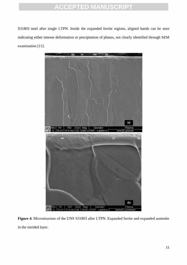
S31803 steel after single LTPN. Inside the expanded ferrite regions, aligned bands can be seen
indicating either intense deformation or precipitation of phases, not clearly identified through SEM
examination [11].
Figure 4. Microstructure of the UNS S31803 after LTPN. Expanded ferrite and expanded austenite
in the nitrided layer.
ACCEPTED MANUSCRIPT
ACC
EPTE
D M
ANU
SCR
IPT
12
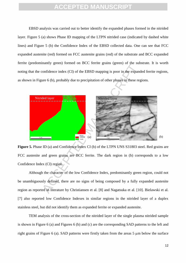
EBSD analysis was carried out to better identify the expanded phases formed in the nitrided
layer. Figure 5 (a) shows Phase ID mapping of the LTPN nitrided case (indicated by dashed white
lines) and Figure 5 (b) the Confidence Index of the EBSD collected data. One can see that FCC
expanded austenite (red) formed on FCC austenite grains (red) of the substrate and BCC expanded
ferrite (predominantly green) formed on BCC ferrite grains (green) of the substrate. It is worth
noting that the confidence index (CI) of the EBSD mapping is poor in the expanded ferrite regions,
as shown in Figure 6 (b), probably due to precipitation of other phases in these regions.
Figure 5. Phase ID (a) and Confidence Index CI (b) of the LTPN UNS S31803 steel. Red grains are
FCC austenite and green grains are BCC ferrite. The dark region in (b) corresponds to a low
Confidence Index (CI) region.
Although the character of the low Confidence Index, predominantly green region, could not
be unambiguously defined, there are no signs of being composed by a fully expanded austenite
region as reported in literature by Christiansen et al. [8] and Nagatsuka et al. [10]. Bielawski et al.
[7] also reported low Confidence Indexes in similar regions in the nitrided layer of a duplex
stainless steel, but did not identify them as expanded ferrite or expanded austenite.
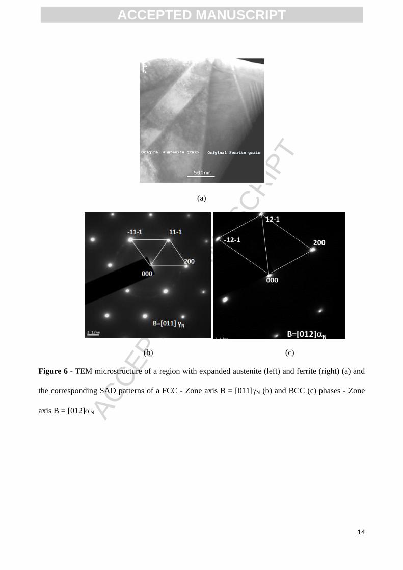
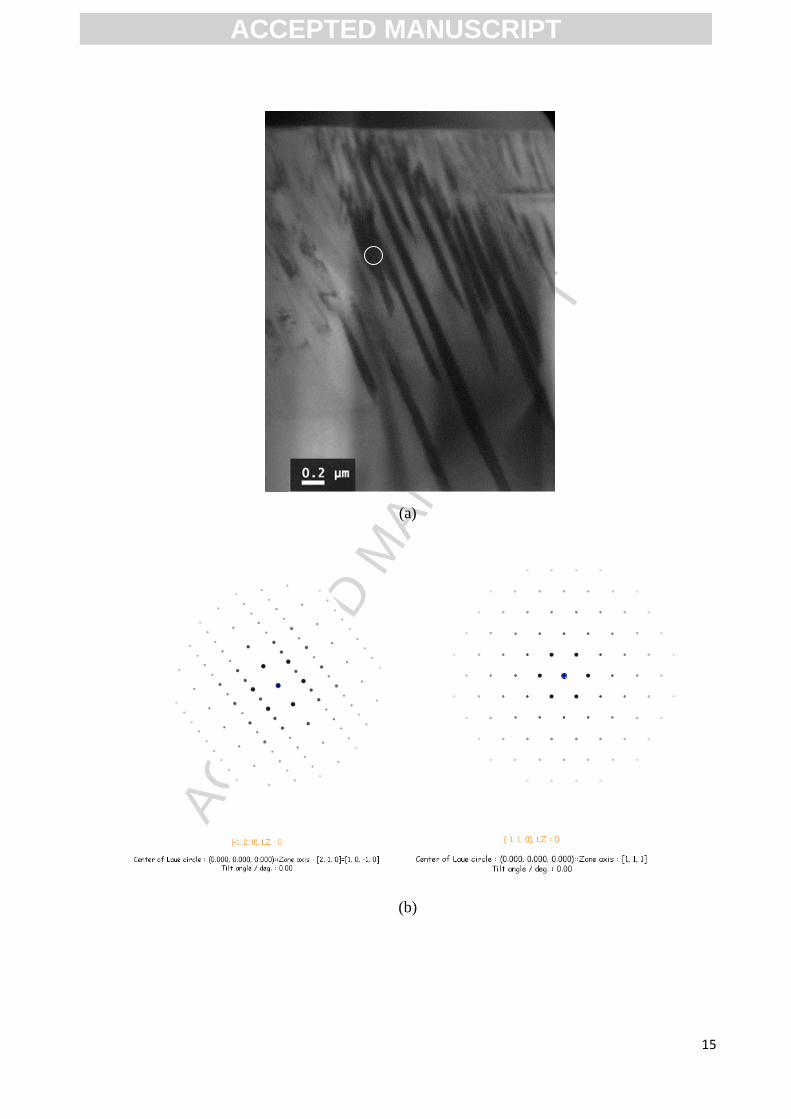
TEM analysis of the cross-section of the nitrided layer of the single plasma nitrided sample
is shown in Figure 6 (a) and Figures 6 (b) and (c) are the corresponding SAD patterns to the left and
right grains of Figure 6 (a). SAD patterns were firstly taken from the areas 5 m below the surface
Nitrided layer
(a) (b)
Nitrided layer
ACCEPTED MANUSCRIPT
ACC
EPTE
D M
ANU
SCR
IPT
13
of the both grains to confirm the original structure of them. It was found that it was austenite and
ferrite grains for the left and right grains, respectively.
Analysis of the SAD patterns taken from the left grain in Figure 6 (a) revealed an FCC
structured pattern of zone B=[110]. When moving up the selected area from the area 5 m below
the surface, to the area close to the surface, the [110] SAD pattern and the orientation remained the
same. D-spacing calculation from the SAD pattern from top and down areas revealed that the d-
spacing of d111 is 0.212 nm and 0.208 nm respectively. This finding is similar to the results of low
temperature plasma nitrided austenitic stainless steels [2]: nitrogen was introduced by plasma
nitriding into the austenite interstitial places and formed a nitrogen supersaturated layer, or so-called
S-phase layer. Figure 6 (c) is the SAD pattern taken from the matrix of the right grain in Figure 6
(a) and the indexing shows a [012] BCC pattern with the crystal constant of a=0.2900 nm, larger
than the 0.2886 nm parameter estimated by XRD and larger than untreated ferrite ones (a=0.2867
nm). When moving the samples from the top to the down side of the ferrite grain (out of the nitride
surface layer), the SAD patterns keep the same orientation but the deformed diffraction spots
featured in Figure 6 (c) were getting sharp and normal. As can be seen in Figures 7 (a) and 8 (a),
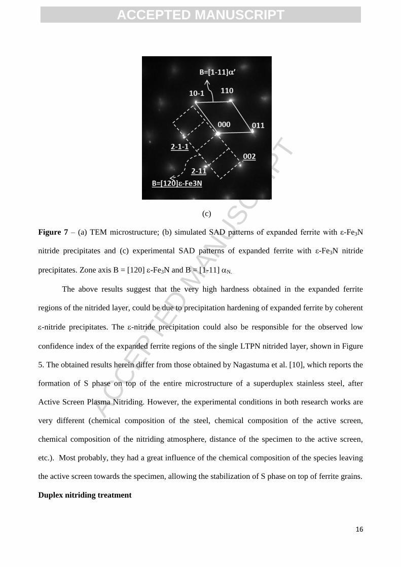
thin slabs were formed within ferrite grains. These slabs where identified as ε-Fe3N nitride,
precipitated from nitrogen-saturated ferrite (αN) during plasma nitriding, as shown in Figure 7 (b).
In Figure 7 (b), simulated and experimental SAD patterns of the ε-Fe3N nitride and bcc ferrite
phases indicate an orientation relationship of [111]α // [120]ε-Fe3N, as can be seen by the double
spots originated from the hexagonal and bcc phases.
ACCEPTED MANUSCRIPT
ACC
EPTE
D M
ANU
SCR
IPT
14
(a)
(b) (c)
Figure 6 - TEM microstructure of a region with expanded austenite (left) and ferrite (right) (a) and
the corresponding SAD patterns of a FCC - Zone axis B = [011]N (b) and BCC (c) phases - Zone
axis B = [012]N
ACCEPTED MANUSCRIPT
ACC
EPTE
D M
ANU
SCR
IPT
15
(a)
(b)
ACCEPTED MANUSCRIPT
ACC
EPTE
D M
ANU
SCR
IPT
16
(c)
Figure 7 – (a) TEM microstructure; (b) simulated SAD patterns of expanded ferrite with ε-Fe3N
nitride precipitates and (c) experimental SAD patterns of expanded ferrite with ε-Fe3N nitride
precipitates. Zone axis B = [120] -Fe3N and B = [1-11] N.
The above results suggest that the very high hardness obtained in the expanded ferrite
regions of the nitrided layer, could be due to precipitation hardening of expanded ferrite by coherent
-nitride precipitates. The -nitride precipitation could also be responsible for the observed low
confidence index of the expanded ferrite regions of the single LTPN nitrided layer, shown in Figure
5. The obtained results herein differ from those obtained by Nagastuma et al. [10], which reports the
formation of S phase on top of the entire microstructure of a superduplex stainless steel, after
Active Screen Plasma Nitriding. However, the experimental conditions in both research works are
very different (chemical composition of the steel, chemical composition of the active screen,
chemical composition of the nitriding atmosphere, distance of the specimen to the active screen,
etc.). Most probably, they had a great influence of the chemical composition of the species leaving
the active screen towards the specimen, allowing the stabilization of S phase on top of ferrite grains.
Duplex nitriding treatment
ACCEPTED MANUSCRIPT
ACC
EPTE
D M
ANU
SCR
IPT
17
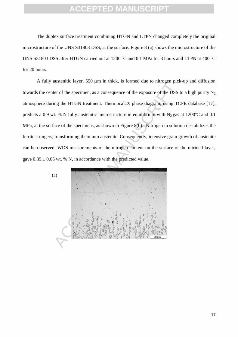
The duplex surface treatment combining HTGN and LTPN changed completely the original
microstructure of the UNS S31803 DSS, at the surface. Figure 8 (a) shows the microstructure of the
UNS S31803 DSS after HTGN carried out at 1200 ºC and 0.1 MPa for 8 hours and LTPN at 400 ºC
for 20 hours.
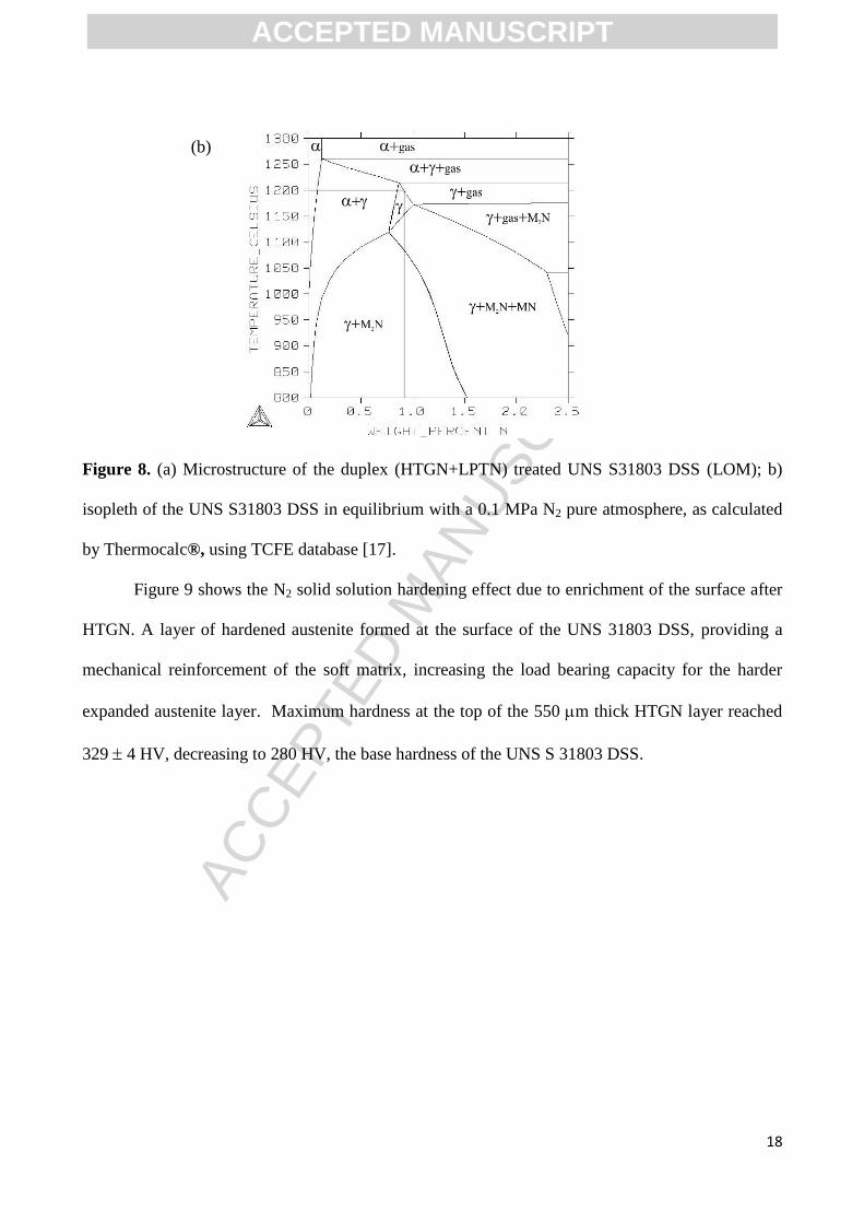
A fully austenitic layer, 550 m in thick, is formed due to nitrogen pick-up and diffusion
towards the center of the specimen, as a consequence of the exposure of the DSS to a high purity N2
atmosphere during the HTGN treatment. Thermocalc® phase diagram, using TCFE database [17],
predicts a 0.9 wt. % N fully austenitic microstructure in equilibrium with N2 gas at 1200ºC and 0.1
MPa, at the surface of the specimens, as shown in Figure 8(b). Nitrogen in solution destabilizes the
ferrite stringers, transforming them into austenite. Consequently, intensive grain growth of austenite
can be observed. WDS measurements of the nitrogen content on the surface of the nitrided layer,
gave 0.89 0.05 wt. % N, in accordance with the predicted value.
(a)
ACCEPTED MANUSCRIPT
ACC
EPTE
D M
ANU
SCR
IPT
18
Figure 8. (a) Microstructure of the duplex (HTGN+LPTN) treated UNS S31803 DSS (LOM); b)
isopleth of the UNS S31803 DSS in equilibrium with a 0.1 MPa N2 pure atmosphere, as calculated
by Thermocalc®, using TCFE database [17].
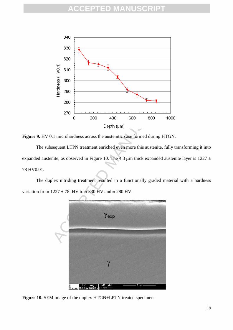
Figure 9 shows the N2 solid solution hardening effect due to enrichment of the surface after
HTGN. A layer of hardened austenite formed at the surface of the UNS 31803 DSS, providing a
mechanical reinforcement of the soft matrix, increasing the load bearing capacity for the harder
expanded austenite layer. Maximum hardness at the top of the 550 m thick HTGN layer reached
329 4 HV, decreasing to 280 HV, the base hardness of the UNS S 31803 DSS.
(b)
ACCEPTED MANUSCRIPT
ACC
EPTE
D M
ANU
SCR
IPT
19
Figure 9. HV 0.1 microhardness across the austenitic case formed during HTGN.
The subsequent LTPN treatment enriched even more this austenite, fully transforming it into
expanded austenite, as observed in Figure 10. The 4.3 m thick expanded austenite layer is 1227 ±
78 HV0.01.
The duplex nitriding treatment resulted in a functionally graded material with a hardness
variation from 1227 ± 78 HV to 330 HV and 280 HV.
Figure 10. SEM image of the duplex HTGN+LPTN treated specimen.
exp
ACCEPTED MANUSCRIPT

ACC
EPTE
D M
ANU
SCR
IPT
20
X-ray diffraction
Figure 11 shows the XRD diffraction patterns of the simply HTGN UNS S31803 specimens.
While the diffraction pattern of the as received samples (Figure 2) clearly show peaks
corresponding solely to ferrite and austenite phases present in the bulk duplex microstructure, the
diffraction pattern of the HTGN specimens exhibit only peaks of austenite. The austenite average
lattice parameter, measured after HTGN is 0.3622 nm. Picard's equation (aN = a + 0.00078 CN)
[18] using Vegard´s constant 0.00078 nm/at% N, valid up to 10 at% N, allows calculating the
nitrogen content (CN) of the high nitrogen austenite (aN) obtaining a value of 0.92 wt.% nitrogen,
in accordance to the Thermocalc® prediction presented in Figure 8(b) and also with the WDS
measurements mentioned above.
Figure 11. XRD diffraction pattern of the HTGN UNS S31803 stainless steel.
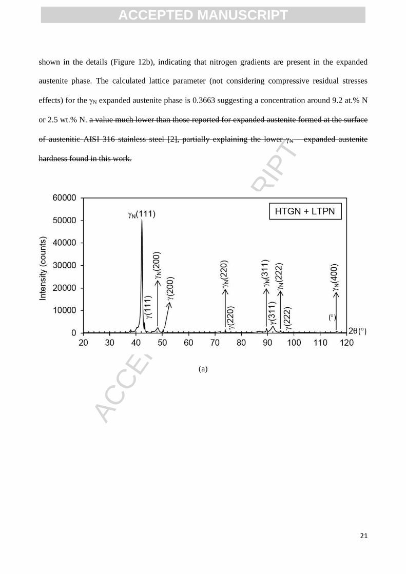
Figure 12a shows the XRD diffraction pattern for the duplex treated material (HTGN +
LTPN). Pairs of FCC peaks are observed, corresponding to the (111), (200), (220), etc. positions.
Due to the low thickness of the LTPN layer, the incident X-ray beam is also diffracting in the fully
non-expanded austenitic substrate. The peaks located in the right position correspond to the
austenitic substrate reflections; while the peaks shifted to lower diffraction angles correspond to the
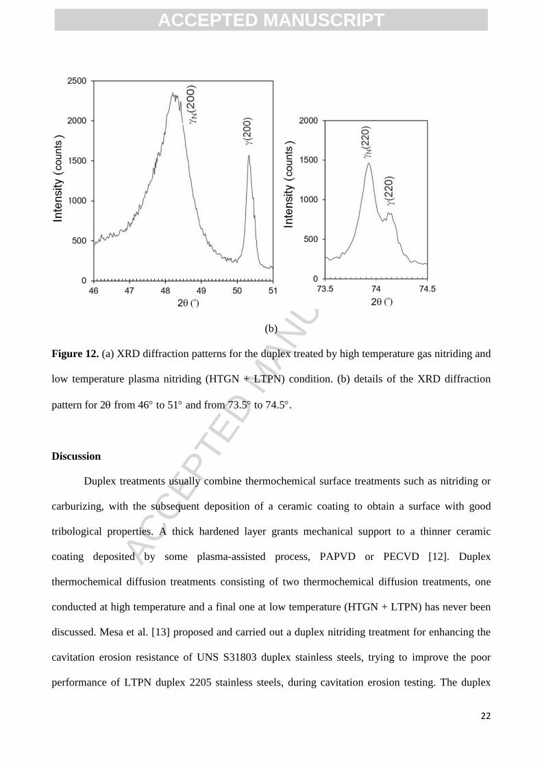
N expanded austenite phase. It is worth noting that the expanded austenite peaks are asymmetric, as
ACCEPTED MANUSCRIPT
ACC
EPTE
D M
ANU
SCR
IPT
21
shown in the details (Figure 12b), indicating that nitrogen gradients are present in the expanded
austenite phase. The calculated lattice parameter (not considering compressive residual stresses
effects) for the N expanded austenite phase is 0.3663 suggesting a concentration around 9.2 at.% N
or 2.5 wt.% N. a value much lower than those reported for expanded austenite formed at the surface
of austenitic AISI 316 stainless steel [2], partially explaining the lower N – expanded austenite
hardness found in this work.
(a)
()
ACCEPTED MANUSCRIPT
ACC
EPTE
D M
ANU
SCR
IPT
22
(b)
Figure 12. (a) XRD diffraction patterns for the duplex treated by high temperature gas nitriding and
low temperature plasma nitriding (HTGN + LTPN) condition. (b) details of the XRD diffraction
pattern for 2 from 46 to 51 and from 73.5 to 74.5.
Discussion
Duplex treatments usually combine thermochemical surface treatments such as nitriding or
carburizing, with the subsequent deposition of a ceramic coating to obtain a surface with good
tribological properties. A thick hardened layer grants mechanical support to a thinner ceramic
coating deposited by some plasma-assisted process, PAPVD or PECVD [12]. Duplex
thermochemical diffusion treatments consisting of two thermochemical diffusion treatments, one
conducted at high temperature and a final one at low temperature (HTGN + LTPN) has never been
discussed. Mesa et al. [13] proposed and carried out a duplex nitriding treatment for enhancing the
cavitation erosion resistance of UNS S31803 duplex stainless steels, trying to improve the poor
performance of LTPN duplex 2205 stainless steels, during cavitation erosion testing. The duplex
ACCEPTED MANUSCRIPT
ACC
EPTE
D M
ANU
SCR
IPT
23
treated UNS S31803 stainless steel showed a more homogeneous variation of microstructure and
less steep hardness gradients from surface towards the ferritic-austenitic core. Mesa et al. [13]
studied methods for improving the cavitation erosion resistance of duplex UNS S31803 stainless
steel. The idea was to compare the High Temperature Gas Nitriding with the Low Temperature
Plasma Nitriding – LTPN surface treatments, carried out on a UNS S31803 duplex stainless steel.
At first, a Low Temperature Plasma Nitriding – LTPN treatment was carried out on the UNS
S31803 stainless steel, without success. The authors observed that the microstructure and
mechanical properties of the LTPN nitrided layer was not homogeneous and did not perform very
well under cavitation erosion conditions. Simultaneously, Mesa carried out a HTGN treatment on
the UNS S31803 duplex stainless steel, obtaining much better cavitation-erosion results, indicating
that the homogeneity of the surface microstructure (fully austenitic) and increased hardness (330
HV) could improve, significantly, the cavitation erosion-erosion resistance of the UNS S31803
duplex stainless steel. Thereafter, the authors decided to investigate if a duplex nitriding treatment
DN (HTGN + LTPN) could improve the performance of the duplex steel under cavitation erosion
testing. The results indicated that the combination of the two thermochemical treatments resulted in
a much better performance.
Comparison between the duplex treated UNS S31803 steel and a low temperature plasma
nitrided UNS S30403 steel, resulted in incubation times almost 9 times greater. The maximum
cavitation wear rate of the LTPN UNS S30403 was 5.5 g/m2h, 180 times greater than the one
measured for the duplex treated UNS S31803 steel. The greater cavitation wear resistance of the
duplex treated UNS S31803 steel, compared to the LTPN treated UNS S30403 steel was explained
by the greater mechanical support the fully austenitic, 330 HV 0.1 hard, 100 μm layer gives to the
expanded austenite layer formed on top of the specimen after LTPN. It was concluded that the
greater mechanical support the thick HTGN nitride layer gives to the hard LTPN expanded
austenite layer formed on top of the specimen, granted good adhesion of the expanded austenite
ACCEPTED MANUSCRIPT
ACC
EPTE
D M
ANU
SCR
IPT
24
layer to the substrate increasing the incubation time for cavitation damage and decreasing the rate of
mass loss during cavitation-erosion.
Indeed, the results reported hereby show that LTPN of the UNS S31803 duplex stainless
steel promotes the formation of a duplex modulated structure composed by expanded ferrite and
expanded austenite on ferrite and austenite grains, respectively. Although chromium nitrides could
not be detected in the nitrided layer, intense coherent -Fe3N nitride precipitation in the expanded
ferrite phase was detected, which led to a strong increase in microhardness of the expanded ferrite
regions. Very steep hardness gradients allows easy spalling and detachment of the thin and hard
(expanded ferrite + expanded austenite) layer.
Pinedo et al. [11] reported a study, aiming a more fundamental understanding of what where
the mechanisms involved in the LTPN surface treatment of duplex stainless steels. In their research
work, carried out in a pulsed plasma DC reactor, the authors reported the formation of a modulated
nitrided layer, composed of expanded ferrite on top of ferrite grains and expanded austenite on top
of austenite grains of the duplex stainless steel microstructure, without any precipitation of
chromium or iron nitrides. Some “deformation bands” were observed, inside expanded ferrite,
which were assigned to intense compressive residual stresses. On the other hand, the results
reported in this manuscript are quite different from those given in reference [11]. Although the
modulated structure reported in the previous paper was also formed after active screen LTPN, the
results show that -Fe3N needles precipitate coherently inside the expanded ferrite regions of the
nitrided layer, sharply increasing the hardness.
The duplex HTGN + LTPN nitriding treatment, consisting of a 4 µm thick, nitrogen rich, 1227
±78 HV 0.01 hard, expanded austenite layer, formed on top of a 550 µm thick, 0.9 wt% N, fully
austenitic layer, ensures a more homogeneous microstructure and gentler hardness gradients.
Accordingly, a better performance should be expected in wear bearing applications in which very
ACCEPTED MANUSCRIPT
ACC
EPTE
D M
ANU
SCR
IPT
25
high loads and high stress concentration are applied, due to the increased load bearing capacity
conferred by the High Temperature Gas Nitriding treatment.
4. Conclusions
1) The single 400ºC low temperature nitriding treatment of the as received UNS S31803
duplex stainless steel led to formation of a modulated nitrided layer composed of expanded
ferrite and expanded austenite, with hardness of 1510 52 HV0.01 and 1360 81 HV0.01,
respectively. The expanded austenite formed on the austenite stringers of the microstructure,
while the expanded ferrite formed on the ferrite stringers of the bulk microstructure.
2) Coherent ε-Fe3N nitrides precipitated inside expanded ferrite with a [111] α // [120] ε-Fe3N.
orientation relationship.
3) High temperature gas nitriding of UNS S31803 stainless steel carried out at 1200ºC, under
0.1 MPa and for 8 hours led to the formation of a 550 µm thick high nitrogen fully austenitic
layer at the surface of the specimens and to surface hardening of the DSS, up to 330 HV0.1.
4) The Duplex Treatment (High Temperature Gas Nitriding, carried out at 1200ºC, 0.1 MPa for
8 hours, followed by Low Temperature Plasma Nitriding at 400ºC, 75%N2+25%H2, 400 Pa
pressure and 20 hours) resulted in a 1227 ± 78 HV hard, 4.3 m thick, expanded austenite
layer, formed on top of a 330 HV hard, high nitrogen, fully austenitic layer.
5) The duplex treatment may result in better wear performance of parts subjected to high levels
of stress concentration
Acknowledgements
To the São Paulo State Research Foundation, FAPESP, process 2012/50890-0 and to the University
of Birmingham, UK, for the financial support,.
ACCEPTED MANUSCRIPT
ACC
EPTE
D M
ANU
SCR
IPT
26
References
[1] I. Alvarez-Armas, Duplex Stainless Steels: Brief History and Some Recent Alloys, Recent
Patents on Mechanical Engineering, 7 (2010) 51-57.
[2] N. Mingolo, C.E. Pinedo, A.P. Tschiptschin - On the formation of expanded austenite during
plasma nitriding of an AISI 316L austenitic stainless steel, Surface and Coatings Technology, 201
(2006) 4215-4218.
[3] Y. Sun, T. Bell, G. Wood, Wear behavior of plasma-nitrided martensitic stainless steel, Wear
178 (1994) 131–138.
[4] B. Larisch, U. Brusky, H.-J. Spies, Plasma nitriding of stainless steels at low temperatures,
Surface and Coatings Technology 116–119 (1999) 205–211.
[5] C. Blawert, B.L. Mordike, Y. Jiráskova, O. Schneeweiss, Structure and composition of
expanded austenite produced by nitrogen plasma immersion ion implantation of stainless steels
X6CrNiTi1810 and X2CrNiMoN2253, Surf. Coat. Tech. 116-119 (1999) 189-198.
[6] J. Bielawski, J. Baranowska, Microstructure and properties of layers on chromium steel, Surf.
Coat. Tech., 200 (2006) 6572-6577.
[7] J. Bielawski, J. Baranowska, Formation of nitrided layers on duplex steel – influence of
multiphase substrate, Surf. Eng. 26 (2010) 299-304.
[8] T. Christiansen, M.A.J. Somers, Characterisation of low temperature surface hardened stainless
steel, E-Structure, Struers Journ. of Materialog. 9 (2006) 1-17.
[9] L. H. Chiu , Y. Y. Su , F. S. Chen, H. Chang - Microstructure and Properties of Active Screen
Plasma Nitrided Duplex Stainless Steel, Journal Materials and Manufacturing Processes, 25 (2010)
316-323.
[10] K. Nagatsuka, A. Nishimoto, K. Akamatsu - Surface hardening of duplex stainless steel by low
temperature active screen plasma nitriding, Surface and Coatings Technology, 205 (2010) S295-
S299.
ACCEPTED MANUSCRIPT
ACC
EPTE
D M
ANU
SCR
IPT
27
[11] C.E. Pinedo, L.B. Varela, A.P. Tschiptschin, Low-temperature plasma nitriding of AISI F51
duplex stainless steel, Surface & Coatings Technology, 232 (2013) 839–843.
[12] Tschiptschin, A.P. Duplex Coatings. In: Wang, Q. Jane; Chung, Yip-Wah. (Org.).
Encyclopedia of Tribology. 1ed.Munich: Springer US, 2013, v. 2, p. 794-800.
[13] D.H. Mesa, C.E. Pinedo, A.P. Tschiptschin, Improvement of the cavitation erosion resistance
of UNS S31803 stainless steel by duplex treatment, Surface & Coatings Technology 205 (2010)
1552–1556.
[14] A. Toro; A. P. Tschiptschin - Chemical characterization of a high nitrogen stainless steel by
optimized electron probe microanalysis - Scripta Materialia 63 (2010) 803-806.
[15] M. Satyapal, A.S. Khanna, A. Joseph - Effect of Temperature on the Plasma Nitriding of
Duplex Stainless Steels – International Journal of Engineering and Inonovative Technology – 2
(2013) 217-222.
[16] R.R.M. Sousa, F.O. Araújo, J.A.P. Costa, A.A. Oliveira, M.S. Melo, C.A. Alves Jr. Cathodic
Cage Nitriding of AISI 409 Ferritic Stainless Steel with the Addition of CH4 Materials Research 15
(2012) 260-265.
[17] Thermo-Calc Software – TCF8 – TCS Steels/Fe-Alloys Database, Version 8.0 –
http://www.thermocalc.com/media/31186/Upgrade_TCFE8-from-TCFE7.pdf . Acessed june 20,
2017.
[18] S. Picard, J.B. Memet, R. SABOT, J.L. Grosseau-Poussard, J.P. Rivière, R. Meilland,
Corrosion behavior, microhardness and surface characterization of low energy, high current ion
implanted austenitic stainless steel. Materials Science and Engineering A, 303 (2001) 163-172.
ACCEPTED MANUSCRIPT
ACC
EPTE
D M
ANU
SCR
IPT
28
Figure 1. As received microstructure of the UNS S31803 steel. LOM.
Figure 2 – Diffraction pattern of the as received UNS S31803 duplex stainless steel.
Figure 3. (a) XRD diffraction pattern of the single LTPN UNS S31803 steel; (b) detail of the XRD
diffraction pattern ranging from 35 to 55.
Figure 4. Microstructure of the UNS S31803 after LTPN. Expanded ferrite and expanded austenite
in the nitrided layer.
Figure 5. Phase ID (a) and Confidence Index CI (b) of the LTPN UNS S31803 steel. Red grans are
FCC austenite and green grains are BCC ferrite. The dark region in (b) corresponds to a low
Confidence Index (CI) region.
Figure 6 - TEM microstructure of a region with expanded austenite (left) and ferrite (right) (a) and
the corresponding SAD patterns of a FCC (b) and BCC (c) phases.
Figure 7 – (a) TEM microstructure; (b) simulated SAD patterns of expanded ferrite with ε-Fe3N
nitride precipitates and (c) experimental SAD patterns of expanded ferrite with ε-Fe3N nitride
precipitates.
Figure 8. (a) Microstructure of the duplex (HTGN+LPTN) treated UNS S31803 DSS (LOM); b)
isopleth of the UNS S31803 DSS in equilibrium with a 0.1 MPa N2 pure atmosphere, as calculated
by Thermocalc®, using TCFE database.
Figure 9. HV0.1 microhardness across the austenitic case formed during HTGN.
Figure 10. SEM image of the duplex HTGN+LPTN treated specimen.
Figure 11. XRD diffraction pattern of the HTGN UNS S31803 stainless steel.
Figure 12. (a) XRD diffraction patterns for the duplex treated by high temperature gas nitriding and
low temperature plasma nitriding (HTGN + LTPN) condition. (b) details of the XRD diffraction
pattern for 2 from 46 to 51 and from 73.5 to 74.5.
Figure captions:
ACCEPTED MANUSCRIPT
ACC
EPTE
D M
ANU
SCR
IPT
29
Highlights
LTPN of 31803 DSS forms a nitrided layer composed by expanded N and N phases.
During LTPN, ε-Fe3N nitrides precipitate in N with [120]ε-Fe3N//[111]N.
A duplex nitriding (DN) treatment (HTGN+LTPN) of 31803 DSS was developed.
(DN) formed a ~4 m thick expanded N layer on top of a 550 m thick layer.
(DN) case microstructure is fully austenitic showing gentler hardness gradients.
ACCEPTED MANUSCRIPT