High Performance FPGA Implementation of Double Precision ...
Yongkyu Choi,1 Min-Hee Lee,2 Moon S. Nam,3 Tae-Hyung Kim,4 and Armin W. Stuedlein5
Development and Implementation of aHigh-Pressure, Double-Acting, Bi-DirectionalLoading Cell for Drilled Shafts
Reference
Choi, Y., Lee, M.-H., Nam, M. S., Kim, T.-H., and Stuedlein, A. W., “Development and Implementation of a
High-Pressure, Double-Acting, Bi-Directional Loading Cell for Drilled Shafts,” Geotechnical Testing
Journal, Vol. 39, No. 2, 2016, pp. 196–205, doi:10.1520/GTJ20140166. ISSN 0149-6115
ABSTRACT
Drilled shaft foundation elements provide a cost-effective foundation alternative for the
support of building and bridge superstructure loads. Bi-directional pile loading tests
(BDPLTs) to evaluate the capacity of drilled shafts have become popular owing to their
capacity to save time and effort as compared to the use of top-down loading tests.
However, the use of BDPLTs requires that production shafts be post-grouted following
testing in order to assure appropriate in-service performance. Commonly used single-acting
loading cells and/or loading cell construction details can pose the potential for the
development of voids following post-grouting due to their monotonic jacking action and
large footprint. This paper described the development and use of high pressure bi-
directional loading cells intended to minimize the possibility of post-test construction
defects. First, a comparison was made between the single-acting and double-acting loading
cells. Second, the results of laboratory calibrations on the pressurized loading cells were
performed, as were component testing of the pumps, hoses, and hydraulic fluid
synchronization lines. Then, the use of the new high pressure double-acting loading cells in
production testing of instrumented shafts was described, and the efficacy of the new
loading cells was illustrated. The new loading cells provided the profession with a load cell
alternative for conducting BDLTs and should serve to help reduce the risk of post-test
grouting defects in drilled shaft foundations.
Keywords
field testing, deep foundations, site infrastructure and construction, cementing/grouting
Manuscript received August 8, 2014;
accepted for publication November 12,
2015; published online January 27, 2016.
1
Professor, Department of Civil
Engineering, Kyungsung Univ., 314-79
Daeyeon-dong, Nam-gu, Busan 608-
736, Korea, e-mail: [email protected]
2
President, G-Tec Engineering Co. Ltd.,
908 Haeundae Officetel, 24 Gunam-ro 18
beon-gil, Haeundae-gu, Busan, Korea,
e-mail: [email protected]
3
Senior Researcher, Korea Expressway
Corporation, 50-5 Sancheok-ri, Dongtan-
myun, Hwasung 445-812, Korea, e-mail:
4
Professor, Department of Civil
Engineering, Korea Maritime and Ocean
Univ., 727 Taejongro, Yeongdo-gu, Busan
606-791, Korea, e-mail:
5
Associate Professor, Oregon State Univ.,
101 Kearney Hall, Corvallis, OR 97331,
e-mail: [email protected]
Copyright VC 2016 by ASTM International, 100 Barr Harbor Drive, PO Box C700, West Conshohocken, PA 19428-2959. 196
Geotechnical Testing Journal
doi:10.1520/GTJ20140166 / Vol. 39 / No. 2 / March 2016 / available online at www.astm.org
Copyright by ASTM Int'l (all rights reserved); Mon May 9 12:07:52 EDT 2016Downloaded/printed byOregon State Univ (Oregon State Univ) pursuant to License Agreement. No further reproductions authorized.

Introduction
Recent trends in building construction across the world indicate
that tall structures, including those 100 stories or higher, are
proliferating to meet the demands of booming urban popula-
tions within areas of high land costs (Tse et al. 2012). Tall struc-
tures include residential and commercial high-rises, offices,
hotels, and mixed-use buildings, all of which comprise the needs
of densely populated urban areas. Correspondingly, the use of
large-diameter driven piles and drilled shafts has increased in
order to provide foundation support for such heavy structures.
Owing to the demand for such buildings, loads required to be
transferred from the superstructures to their foundations are
increasing in magnitude so that design loads ranging from 10 to
60 MN are common (Schmertmann et al. 1998; Osterberg
1998), and test loads of up to 320 MN are now a reality
(Hayes 2012).
The conventional static quick pile loading test (ASTM
D1143/D1143M-07(2013)) is commonly used in conjunction
with conventional top-down testing to check the load bearing
capacity of constructed deep foundations. This method, while
reliable and widely accepted, suffers from certain limitations
when testing the capacity of large-diameter deep foundations
because of the significant reaction system required to displace
the tested element sufficiently (Choi and Nam 2012). Addi-
tionally, the likelihood of detecting “soft toe” conditions or
other construction-related defects using top-down methods
can be significantly reduced if the test loads remain well below
the ultimate shaft resistance of a drilled foundation. To help
meet the challenge associated with developing sufficient resist-
ance, the bi-directional pile loading test (BDPLT) was devel-
oped as a feasible alternative test method to the top-down
static loading test. The BDPLT achieves test loads by reacting
against all or a majority of the shaft resistance of the con-
structed element; hence pushing the element in opposing
directions simultaneously. The Osterberg cell test (O-cell test),
a type of BDPLT, is the most widely used in the world and
uses hydraulic pressure to displace single-acting hydraulic cells
to generate the required test load (Osterberg 1986).
However, some single-acting load cells can experience defi-
ciencies by virtue of its operation, construction detailing, and by
the end-user in the field. For instance, after a loading test, a
void is generated inside the cell. If the foundation element will
perform as a production shaft, the space must be filled by struc-
tural grout to avoid a reduction in the strength of the drilled
shaft. Grouting is possible in single-acting loading cell systems,
but the integrity of the grouted voids cannot be verified.
Depending on the location of the loading cell, voids may serve
to significantly reduce the load carrying capacity of the drilled
shaft (O’Neill et al. 2002; Petek et al. 2002; Iskander et al. 2003;
Nam and Choi 2007), and the effect of the voids could be
encountered during construction of the supported structure, or
during a strength or extreme limit state when performance is
most critical. Furthermore, because low-pressure cells are con-
structed using larger diameters to achieve their target loads, the
cells require a large foot print, exacerbating the potential for
voids due to improper grouting between and within the cells to
result in poor shaft performance. To address potential short-
comings, Lee et al. (2007) developed the first double-acting
BDPLT cell; however, this initial effort used typical hydraulic
pressures and suffered from the same cell pressurization
sequence as that of single-acting cells (described in greater detail
below).
This paper describes the background and development of
a new high pressure, double-acting bi-directional loading cell,
designed to address the potential shortcomings of low pres-
sure single- and double-acting loading cells, and its use in two
full-scale axial loading tests of constructed drilled shafts. First,
a brief review of BDPLT systems is provided. Then, the devel-
opment of the high pressure double-acting bi-directional load-
ing cell is described, including the factors affecting grouting
quality, loading capability, and the hydraulic flow system. The
results of laboratory tests required to assess the cell capacity,
consistency of hydraulic pressure, and integration of the
hydraulic system are described. To illustrate the successful
application of the high-pressure double-acting loading cell,
two full-scale loading tests of large-diameter drilled shafts
constructed on a building site in Korea are presented, includ-
ing load-displacement curves and the load-transfer observed
using instrumentation distributed along the shafts. This paper
intends to introduce the feasibility of the high pressure
double-acting loading cell system for performing loading tests
and reducing the possibility of post-construction defects in
production foundation elements.
Background on Bi-Directional
Loading Tests
SINGLE-ACTING LOADING CELLS
Bi-directional pile loading tests were introduced by Osterberg
(1986) and applied to the first commercial project in 1987;
following the application of bi-directional tests to many
post-Northridge bridge foundation elements constructed in
California circa 1995, the BDPLT became largely accepted in
the public transportation infrastructure sector (Hayes 2012).
The Osterberg cell, or O-cell, is the single-acting hydraulic
“jacking element” that forces one portion of a drilled shaft to
react against the other. Single-acting cells presently range in
diameter from 230 to 860mm in diameter, delivering uniaxial
forces of approximately 1.8 to 27 MN, respectively, when used
in single-cell arrangements (Brown et al. 2010). Assuming
adequate soil resistance is available for reaction, the total load
provided by single-acting cells are limited by the supply of
CHOI ET AL. ON HIGH PRESSURE & DOUBLE-ACTING BDPLT 197
Copyright by ASTM Int'l (all rights reserved); Mon May 9 12:07:52 EDT 2016Downloaded/printed byOregon State Univ (Oregon State Univ) pursuant to License Agreement. No further reproductions authorized.

hydraulic pressure; typical tests are carried out with a maximum
pressure of 70MPa (10,000 psi) or less (e.g., LoadTest 2005).
Nonetheless, BDPLTs can greatly exceed 53 MN by using
multiple single-acting cells at a given elevation and multiple
elevations to mobilize various portions of the shaft and toe
resistance; Hayes (2012) reports test loads as large as 321 MN
for multi-stage testing of drilled shafts.
For efficiency, loading tests are often conducted on pro-
duction drilled shafts. However, the expansion of the single-
acting cell(s) necessarily creates: (1) a void between the top
and bottom loading plates that must be filled, and (2) a void
within the cell itself following removal of the hydraulic fluid
(Fig. 1). In order to strengthen the shaft section at the location
of the single-acting cell(s), grout is pumped into the void
spaces via cross-hole sonic logging tubes placed for the pur-
poses of verifying shaft integrity prior to load testing or other
dedicated conduits. Upon completion of a loading test, the
top and base plates remain in their expanded state because of
the inability of the loading cells to be retracted. Therefore, the
possibility of voids or poorly distributed grout exists owing to
the difficulty of grouting around and within the expanded
loading cells, which can occupy a significant footprint of the
shaft cross-section.
NEWHIGH PRESSURE DOUBLE-ACTING LOADING CELL
The high-pressure and double-acting BDPLT has been
developed to overcome some of the possible limitations of the
low-pressure, single-acting bi-directional pile load tests, which
include: (1) the possibility of poor grout integrity or distribu-
tion, (2) use of high pressures and therefore larger loads for a
given cell diameter, and (3) the sequence of pressurization of
the loading cells, which may affect the concentricity of the
applied load. Each of these aspects is described in more detail
below.
Following the BDPLT, the voids within single-acting cells
are grouted to reduce the potential for poor structural perform-
ance. Grout is pumped into each cell until grout exits a return
line, which should indicate that grouting of the void has been
successfully accomplished (Fig. 1(a)–1(c)). However, this proce-
dure could result in the existence of post-grouting voids, which
can be difficult to detect and remediate. Should voids in fact
exist and the shaft is placed into service, the structural integrity
of the shaft may prove insufficient if it experiences a strength
limit event, for which loads may be transferred to deeper por-
tions of the drilled shaft element. Whenever possible, coring of
the post-grouted zone should be performed so that the integrity
of samples (e.g., continuity, stiffness, and strength) can be
evaluated and compared to the design structural concrete speci-
fications; coring into the loading cell itself for verification of
void grouting is largely infeasible. However, the use of a double-
acting BDPLT cell, as shown in Fig. 1(d)–1(f), can be used to
mitigate the likelihood of poor grout integrity. A double-acting
cell is a cylinder in which pressurized fluid can alternatively act
to expand or retract the loading cell, and this allows for the for-
mation of a uniform void space between the loading cells and
the base plate that is easier to grout.
Typical single-acting loading cells use fluids pressurized to
a maximum of 70MPa; this particular element of a loading
cell is of consequence since the fluid pressure directly controls
the capacity of the loading cell. In practice, the new high pres-
sure double-acting cell us typically pressurized to 100MPa,
FIG. 1 Post-test grouting procedures for single-(a)–(c) and double-acting
(d)–(f) bi-directional loading tests: (a) voids in single-acting cells
following loading, (b) grouting of voids between loading plates and
cells, and (c) grouting complete, (d) voids in double-acting cell
following loading, (e) retraction of loading cells followed by grouting,
and (f) grouting complete.
Geotechnical Testing Journal198
Copyright by ASTM Int'l (all rights reserved); Mon May 9 12:07:52 EDT 2016Downloaded/printed byOregon State Univ (Oregon State Univ) pursuant to License Agreement. No further reproductions authorized.
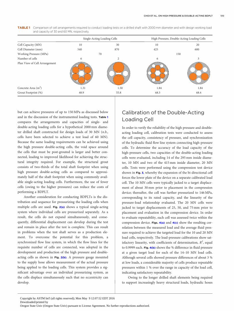
but can achieve pressures of up to 150MPa as discussed below
and in the discussion of the instrumented loading tests. Table 1
compares the arrangements and capacities of single- and
double-acting loading cells for a hypothetical 2000mm diame-
ter drilled shaft constructed for design loads of 30 MN (n.b.,
cells have been selected to achieve a test load of 60 MN).
Because the same loading requirements can be achieved using
the high pressure double-acting cells, the void space around
the cells that must be post-grouted is larger and better con-
nected, leading to improved likelihood for achieving the struc-
tural integrity required. For example, the structural grout
consists of two-thirds of the total shaft footprint when using
high pressure double-acting cells as compared to approxi-
mately half of the shaft footprint when using commonly avail-
able single-acting loading cells. Furthermore, the use of fewer
cells (owing to the higher pressures) can reduce the costs of
performing a BDPLT.
Another consideration for conducting BDPLTs is the dis-
tribution and sequence for pressurizing the loading cells when
multiple cells are used. Fig. 2(a) shows a typical single-acting
system where individual cells are pressurized separately. As a
result, the cells do not expand simultaneously, and conse-
quently, differential displacement can develop during the test
and remain in place after the test is complete. This can result
in problems when the test shaft serves as a production ele-
ment. To overcome the potential for this problem, a
synchronized flow line system, in which the flow lines for the
requisite number of cells are connected, was adopted in the
development and production of the high pressure and double-
acting cells as shown in Fig. 2(b). A pressure gauge mounted
to the supply hose allows measurement of the actual pressure
being applied to the loading cells. This system provides a sig-
nificant advantage over an individual pressurizing system, as
the cells displace simultaneously such that no eccentricity can
develop.
Calibration of the Double-Acting
Loading Cell
In order to verify the reliability of the high pressure and double-
acting loading cell, calibration tests were conducted to assess
the cell capacity, consistency of pressure, and synchronization
of the hydraulic fluid flow line system connecting high-pressure
cells. To determine the accuracy of the load capacity of the
high-pressure cells, two capacities of the double-acting loading
cells were evaluated, including 14 of the 295mm inside diame-
ter, 10 MN and two of the 415mm inside diameter, 20 MN
cells. Tests were performed using the compression test device
shown in Fig. 3, whereby the expansion of the bi-directional cell
forces the lower plate of the device on a separate calibrated load
cell. The 10 MN cells were typically jacked to a target displace-
ment of about 30mm prior to placement in the compression
device; thereafter, the cell was further pressurized to 146MPa,
corresponding to its rated capacity, and the linearity of the
pressure-load relationship evaluated. The 20 MN cells were
jacked to target displacements of 25, 50, and 75mm prior to
placement and evaluation in the compression device. In order
to evaluate repeatability, each cell was assessed twice within the
compression device. Figs. 4(a) and 4(c) show the resulting cor-
relation between the measured load and the average fluid pres-
sure required to achieve the targeted load for the 10 and 20 MN
load cells, respectively. The load-pressure calibrations show sat-
isfactory linearity, with coefficients of determination, R2, equal
to 0.9999 each. Fig. 4(b) shows the % difference in fluid pressure
at a given target load for each of the 14–10 MN load cells.
Although several cells showed pressure differences of about 3 %
at low loads, a considerable majority of cells produce repeatable
pressures within 1 % over the range in capacity of the load cell,
indicating satisfactory repeatability.
Owing to the longer drilled shaft elements being required
to support increasingly heavy structural loads, hydraulic hoses
TABLE 1 Comparison of cell arrangements required to conduct loading tests on a drilled shaft with 2000 mm diameter and with design working load
and capacity of 30 and 60 MN, respectively.
Single-Acting Loading Cells High Pressure, Double-Acting Loading Cells
Cell Capacity (MN) 10 30 10 20
Cell Diameter (mm) 540 870 425 600
Working Pressure (MPa) 70 150
Number of cells 6 2 6 3
Plan View of Cell Arrangement
Concrete Area (m2) 1.31 1.50 1.84 1.84
Grout Footprint (%) 48.9 55.8 68.3 68.4
CHOI ET AL. ON HIGH PRESSURE & DOUBLE-ACTING BDPLT 199
Copyright by ASTM Int'l (all rights reserved); Mon May 9 12:07:52 EDT 2016Downloaded/printed byOregon State Univ (Oregon State Univ) pursuant to License Agreement. No further reproductions authorized.

have necessarily increased in length. Higher pressures and lon-
ger hoses generate potential implications of energy losses when
pressurizing to achieve a new loading increment; therefore, an
investigation of the sensitivity of fluid pressure to hose length
and supply pressure was required to establish an appropriate
calibration procedure if deemed necessary. The test program for
the pressure hose calibration checks consisted of checking 50m
hoses along intervals of 10, 20,…,50m in length and with pump
supply pressures ranging from 20, 40,…,100MPa. Four pressure
gages were installed in series at intervals of 10m at the hose
connections in order to observe the potential loss in pressure
(energy). Fig. 5(a) shows the variation of pressure as a function
of hose length and pump supply pressure; as indicated, no sig-
nificant variation in pressure was noted along the length of the
50m hoses. Additionally, the exterior diameter of the hose was
measured to check for deformations caused by the application
of pressure during the testing. The maximum increase of the
exterior diameter of the hose was approximately 0.5mm; this
amount was considered negligible.
In order to show the stability in the pressure for the
hydraulic supply lines, fittings, and pumps used to conduct a
high-pressure double-acting BDPLT, high-pressure cells were
connected to the synchronized oil flow line system. A pump
supply pressure of 116MPa was applied and maintained for
24 h, and the variation in pressure with time and location along
the supply line is shown in Fig. 5(b) relative to the supply pres-
sure. For the supply pressure, the Fig. 5(b) presents the variation
in pressure with respect to the initially supplied pressure,
whereas the % difference in instantaneous pressure is reported
for the pressure at intermediate supply locations. At each loca-
tion, the pressure remained relatively stable with respect to the
supply pressure and with no significant fluctuations measured
over the during the 24 h testing time.
FIG. 2
Pressurizing systems for bi-directional loading
tests: (a) individually-operated single-acting
loading cells, and (b) simultaneously-operated
double-acting loading cells.
FIG. 3 Schematic of the compression test device and setup used to evaluate
repeatability of load cell measurements.
Geotechnical Testing Journal200
Copyright by ASTM Int'l (all rights reserved); Mon May 9 12:07:52 EDT 2016Downloaded/printed byOregon State Univ (Oregon State Univ) pursuant to License Agreement. No further reproductions authorized.

Based on these calibration checks on the production-
quality components of the high-pressure double-acting loading
cell, it appears that the loading cell can support the purpose of
conducting project-critical bi-directional loading tests. Its use in
practice is demonstrated in the remainder of the paper.
Application of New Loading Cell
for Evaluation of Structure
Foundation Support
In order to demonstrate the applicability of the new high-
pressure double-acting loading cells, two instrumented test
shafts (Loading Tests T-1 and T-2) performed at the same site,
though with different stratigraphies, are described below. The
tests were conducted to establish the load-transfer and load-
displacement response of representative drilled shafts proposed
to support an 80-story mixed-use high rise building with five
basement stories below grade. Loading test T-1 was performed
with the loading cell placed at the base of the shaft, whereas
loading test T-2 was conducted with the loading cell placed 2m
FIG. 4 Calibration and repeatability of new double-acting bi-directional
loading cells: (a) results of 14–10 MN load cells, (b) % difference in
pressure required to achieve a given load for the 10 MN load cells,
and (c) results for the two 20 MN load cells.
FIG. 5 Pressure tests on supply hoses (a) check on pressure losses along
10 m intervals of 50 m hose, and (b) check on time-rate supply of
pressure.
CHOI ET AL. ON HIGH PRESSURE & DOUBLE-ACTING BDPLT 201
Copyright by ASTM Int'l (all rights reserved); Mon May 9 12:07:52 EDT 2016Downloaded/printed byOregon State Univ (Oregon State Univ) pursuant to License Agreement. No further reproductions authorized.

above the base of the shaft. Both loading tests were performed
in general accordance with ASTM D1143.
LOADING TEST T-1
Loading test T-1 was performed on a 34.5m long, 2.5-m
diameter drilled shaft. Fig. 6(a) provides a representative subsur-
face profile of the geologic conditions, which includes a 12m
thick layer of poorly-graded, loose to medium dense alluvial
sand overlying 7.5m of highly variable residual soil, overlying
22m of weathered igneous rock, underlain by soft igneous rock
of unknown thickness. Intact specimens of the soft rock indi-
cated unconfined compressive strengths of 50MPa. Shaft T-1
was installed and tested following excavation of the basement
parking levels, such that the top of the shaft was located at a
depth of 13m below adjacent grade. To achieve the target uni-
axial test load of 80 MN, four 20 MN capacity high-pressure
double acting loading cells were arranged symmetrically at the
base of the test shaft as shown in Fig. 7(a). Displacements exhib-
ited by each of the two loading plates were observed using three
independent telltales set within casings (Fig. 7(a)). Two pairs of
strain gages were distributed along ten elevations to observe the
load-transfer distribution with bi-directional displacement
(Fig. 6(a)). Following placement of the reinforcement cage and
instrumented loading plates, structural concrete was tremied to
the base of the shaft through one of several access ports and
grouted in a bottom-up sequence. The loading test was initiated
following adequate strength gain of the concrete, confirmed
after 28 days.
Generally, loading tests are performed until one of three
limiting criteria are met: the pre-determined maximum test
load has been achieved, the maximum travel of the loading cell
has been reached, or the maximum cell pressure has been real-
ized. Initially, the loading of shaft T-1 was performed using
5 MN increments held for 30min. The project team then
changed the loading protocol so that loading increments were
applied after a one hour hold or when the rate of movement
dropped to 0.25mm per hour, whichever came first. Although
the foundation design required a capacity of 60 MN, the test
was concluded upon reaching the maximum cell pressure (i.e.,
cell capacity) of 150MPa, corresponding to a uniaxial load of
80 MN. The load-displacement response for the upper and
lower test plates of drilled shaft test T-1 is shown in Fig. 8(a),
whereas the load transfer along the shaft is shown in Fig. 8(b).
Upward and downward displacements at the 80 MN test load
were 21 and 32mm, respectively. The benefit of bi-directional
FIG. 6
Soil and instrument profiles for (a) drilled
shaft test T-1, and (b) drilled shaft test T-2.
FIG. 7 Distribution of high pressure, double-acting loading cells, and various
telltale casings on 2210 mm diameter loading plates for (a) test shaft
T-1, and (b) test shaft T-2.
Geotechnical Testing Journal202
Copyright by ASTM Int'l (all rights reserved); Mon May 9 12:07:52 EDT 2016Downloaded/printed byOregon State Univ (Oregon State Univ) pursuant to License Agreement. No further reproductions authorized.

testing is apparent in consideration of the weathered igneous
rock providing the majority of load transfer. Use of standard
penetration tests or unconfined compression tests of rock cores
would likely produce significantly lower, as well as less reliable,
rates of load transfer than that revealed during the instrumented
loading test. For example, the shaft resistance observed in the
weathered igneous rock, which is difficult to sample, was
observed to range from approximately 230 to 650 kPa. Follow-
ing completion of the test, the loading cells were retracted from
the base plate to eliminate the voids within the cells and provide
easier and more uniform post-test grouting between the base
plate and the cells (Fig. 1). Following retraction of the loading
cells, the newly created annular space was grouted to maintain
the structural integrity of the shaft, with grout pressures ranging
from 0.4 to 1.0MPa (depending on the depth of the loading
cells and grout stage) and 28-day compressive strengths greater
than 60MPa.
LOADING TEST T-2
The second loading test was performed on a 21.6m long, 2.5m
diameter drilled shaft, shown in Fig. 6(b) and constructed
within a slightly different stratigraphy as that of test shaft T-1.
At this location, a 26m thick deposit of poorly-graded sand
overlies a relatively thin, 3m thick layer of the weathered igne-
ous rock, underlain in turn by the deep soft igneous rock layer.
The base of the shaft was embedded approximately 11m in the
soft rock layer. Six high-pressure double-acting 20 MN loading
cells with a maximum uniaxial capacity of 120 MN were
arranged on steel loading plates as shown in Fig. 7(b), and were
placed 2m above the base of the shaft. Two pairs of strain gages
FIG. 8 Performance of test shaft T-1: (a) load-displacement curves of upper
and lower steel plates, and (b) load transfer observed above loading
plates for selected load increments.
FIG. 9 Performance of test shaft T-2: (a) load-displacement curves of upper
and lower steel plates, and (b) load transfer observed above loading
plates for selected load increments.
CHOI ET AL. ON HIGH PRESSURE & DOUBLE-ACTING BDPLT 203
Copyright by ASTM Int'l (all rights reserved); Mon May 9 12:07:52 EDT 2016Downloaded/printed byOregon State Univ (Oregon State Univ) pursuant to License Agreement. No further reproductions authorized.
were positioned at 12 elevations to observe the load transfer
distribution as shown in Fig. 6(b).
Based on the observed load transfer of test shaft T-1, load
increments were reduced to 3 MN for the testing of T-2 in order
to better observe the development of shaft resistance. These
smaller loading increments, which were held for the shorter
duration of 1 h or upon reaching a settlement rate of 0.25mm
per hour, were applied until achieving the target maximum test
load of 90 MN. Although the test load could have continued to
120 MN with regard to the high pressure cell capacity, the test
was terminated at the lower load to minimize the potential for
damage to shaft T-2, which was going to be used as a working
foundation to support the 80-story high-rise. Peak upward and
downward displacements of 17 and 25mm were observed at the
maximum test load as shown in Fig. 9(a), and these displace-
ments reflect a 1 h hold, over which 1.8 and 1.3mm creep dis-
placement occurred for the upper and lower plate, respectively.
Fig. 9(b) shows the load transfer distribution for test shaft T-2.
The load transfer deduced from the strain gages indicated rela-
tively similar rates of load shedding in the soft rock layer above
(�1700 kPa) and below (�1950 kPa) the double-acting loading
cells. Owing to the relatively loose density of the alluvium at the
location of test T-2, significantly less load-transfer was shown to
occur in the uppermost soil layers as compared to T-1, of which
the upper portion of the shaft was constructed in the residual
soil. Loading test T-2 also illustrated the significant variation in
rock quality over small distances in the footprint of the building
site, typical of igneous formations. Following conclusion of the
loading tests and verification of design assumptions, the con-
tractor proceeded with the high-rise construction. The high-
pressure and double-acting loading cells were shown to success-
fully perform their intended function.
Summary and Conclusions
Drilled shaft foundations represent significant investments in
civil infrastructure, and efforts to improve their construction
quality are welcome to owner, engineer, and contractor alike.
This paper describes the development of a new, high pressure
double-acting loading cell for use in bi-directional pile loading
tests (BDPLT). The use of higher pressures (up to 150MPa)
in the double-acting loading cell leads to the development of
higher capacities at a given cell diameter than a typical load-
ing cell, which typically uses a maximum target pressure of
70MPa. The use of a double-acting loading cell is also advan-
tageous, as the cells can be retracted from the base plate fol-
lowing testing, again allowing a higher degree of confidence in
the distribution of post-test grouting and minimization of
grout voids.
The new high pressure double-acting loading cells were
subjected to a number of calibration checks to illustrate their
production-level quality. Calibrations of the target load and
pump pressure for 10 and 20 MN cells show a high degree of
linearity, with very little deviation in required pumping pres-
sure between replicate tests. The typical high pressure pump,
hoses, and hydraulic fluid synchronization lines used with the
bi-directional loading cells were shown to maintain approxi-
mately 116MPa of pressure over 24 h hold periods. Finally,
the use of the new high pressure double-acting loading cells
were illustrated through a case history of a high-rise building
project, where two instrumented test shafts, 2500mm in diam-
eter and 34.5 and 21.6m in length were tested. The bi-
directional loading cells were shown to satisfactorily displace
the upper and lower loading plates of each test shaft, and
illustrate the load transfer possible in the weathered and intact
igneous rock. Optimization of the building foundation lengths
was then possible based on the results of these loading tests.
Use of the high pressure double-acting bi-directional loading
cells is now common in Korea and its use worldwide should
continue to grow.
References
ASTM D1143/1143M-07, 2013: Standard Test Methods forDeep Foundations Under Static Axial Compressive Load,ASTM International, West Conshohocken, PA, www.astm.org
Choi, Y. and Nam, M. S., 2012, “Case Study of Load Capacitiesfor Bi-Directional Pile Load Tests,” Int. J. Geo-Eng., Vol. 4,No. 1, pp. 5–10.
Hayes, J. A., 2012, “The Landmark Osterberg Cell Test,” DeepFoundations, Nov/Dec 2012, pp. 45–49.
Iskander, M., Roy, D., Kelley, S., and Ealy, C., 2003, “DrilledShaft Defects: Detection, and Effects on Capacity in VarvedClay,” J. Geotech. Geoenviron. Eng., Vol. 129, No. 12,pp. 1128–1137.
Lee, C.-S., Lee, M.-H., Kim, S.-I., and Choi, Y., 2007, “Study onDevelopment of the Bi-Directional High Pressure Pile LoadTest (BDH PLT) and Its Application,” Kor. Geotech. Soc.,Vol. 23, No. 6, pp. 23–36.
LoadTest, 2005, “Report on Drilled Pile Load Testing (Oster-berg Method), TB-1 (DSSB), New Songdo City Project,Incheon, Korea,” Data Report, Daewang E & C Co., Buk-Gu,Busan, Korea.
Nam, M. and Choi, Y., 2007, “Structural Resistance Factors forShear Loading in Drilled Shafts With Minor Flaws Based onExperimental Study,” KSCE J. Civ. Eng., Vol. 11, No. 5,pp. 243–252.
O’Neill, M., Tabsh, S. W., and Sarhan, H., 2002, “Response ofDrilled Shafts With Minor Flaws to Axial and LateralLoads,” Eng. Struct., Vol. 25, No. 1, pp. 47–56.
Osterberg, J. O., 1986, “Device for Testing The Load BearingCapacity of Concrete-Filled Earthen Shafts,” U.S. Patent No.4,614,110.
Osterberg, J. O., 1998, “The Osterberg Load Test Method forBored and Driven Piles – The First Ten Years,” Proceedingsof the 7th International Conference and Exhibition on Pilingand Deep Foundations, Vienna, Austria, June 15–17, 1998,DFI, Hawthorne, NJ, pp. 1–17.
Geotechnical Testing Journal204
Copyright by ASTM Int'l (all rights reserved); Mon May 9 12:07:52 EDT 2016Downloaded/printed byOregon State Univ (Oregon State Univ) pursuant to License Agreement. No further reproductions authorized.

Petek, K., Felice, C., and Holtz, R., 2002, “Capacity Analysis ofDrilled Shafts With Defects,” Deep Foundations 2002, GSPNo. 116, ASCE, Reston, VA, pp. 1120–1135.
Schmertmann, J. H., Hayes, J. A., Molnit, T., and Osterberg,J. O., 1998, “O-Cell Testing Case Histories Demonstrate theImportance of Bored Pile (Drilled Shaft) ConstructionTechnique,” presented at the 4th International Conferenceon Case History in Geotechnical Engineering, St. Louis, MO,
March 9–12, 1998, Missouri University of Science and Tech-nology, Rolla, MO, Missouri University of Science and Tech-nology, Rolla, pp. 1103–1115.
Tse, K., Kwok, K., and Tamura, Y., 2012, “Performance andCost Evaluation of a Smart Tuned Mass Damper forSuppressing Wind-Induced Lateral-Torsional Motion ofTall Structures,” J. Struct. Eng., Vol. 138, No. 4, pp.514–525.
CHOI ET AL. ON HIGH PRESSURE & DOUBLE-ACTING BDPLT 205
Copyright by ASTM Int'l (all rights reserved); Mon May 9 12:07:52 EDT 2016Downloaded/printed byOregon State Univ (Oregon State Univ) pursuant to License Agreement. No further reproductions authorized.