
Development and human performance evaluation of a ground ... · development and human performance...
74
Wayne State University Wayne State University eses 1-1-2011 Development and human performance evaluation of a ground vehicle robotic force-feedback tele- operation system Ankur Saraf Wayne State University, Follow this and additional works at: hp://digitalcommons.wayne.edu/oa_theses Part of the Electrical and Computer Engineering Commons , and the Robotics Commons is Open Access esis is brought to you for free and open access by DigitalCommons@WayneState. It has been accepted for inclusion in Wayne State University eses by an authorized administrator of DigitalCommons@WayneState. Recommended Citation Saraf, Ankur, "Development and human performance evaluation of a ground vehicle robotic force-feedback tele-operation system" (2011). Wayne State University eses. Paper 80.
Transcript of Development and human performance evaluation of a ground ... · development and human performance...

Wayne State University
Wayne State University Theses
1-1-2011
Development and human performance evaluationof a ground vehicle robotic force-feedback tele-operation systemAnkur SarafWayne State University,
Follow this and additional works at: http://digitalcommons.wayne.edu/oa_theses
Part of the Electrical and Computer Engineering Commons, and the Robotics Commons
This Open Access Thesis is brought to you for free and open access by DigitalCommons@WayneState. It has been accepted for inclusion in WayneState University Theses by an authorized administrator of DigitalCommons@WayneState.
Recommended CitationSaraf, Ankur, "Development and human performance evaluation of a ground vehicle robotic force-feedback tele-operation system"(2011). Wayne State University Theses. Paper 80.

DEVELOPMENT AND HUMAN PERFORMANCE EVALUATION OF A GROUND VEHICLE ROBOTIC FORCE-FEEDBACK TELE-OPERATION SYSTEM
by
ANKUR SARAF
THESIS
Submitted to the Graduate School
of Wayne State University
Detroit, Michigan
in partial fulfillment of the requirements
for the degree of
MASTER OF SCIENCE
2011
MAJOR: ELECTRICAL ENGINEERING
Approved by
Date Advisor

© COPYRIGHT BY
ANKUR SARAF
2011
All Rights Reserved

ii
DEDICATION
This is dedicated to my family.
Your love and support helped me achieve my goals.

iii
ACKNOWLEDGEMENTS
I would like to thank Dr. Abhilash Pandya for all the assistance and guidance he
has provided. His guidance was helpful not only for the thesis but also towards my
career growth and development. I consider him to be a very friendly mentor who is
always ready to help. I would like to thank Dr. Darin Ellis for all his support and precious
feedback. My sincere gratitude goes to Dr. Pepe Siy and Dr. Syed Mahmud. I would
also like to thank Shawn Hunt, Alex Cao, Luke Reisner, Vishal Lowalekar and rest of
the SSIM-CARES team for their help and much required feedback at different stages of
the research.

iv
TABLE OF CONTENTS
Dedication ........................................................................................................................ii
Acknowledgements ......................................................................................................... iii
Table of Contents ............................................................................................................iv
List of Tables ...................................................................................................................vi
Table of figures .............................................................................................................. vii
Chapter 1: Background and significance ......................................................................... 1
1.1 Background ........................................................................................................ 1
1.2 Motivation ........................................................................................................... 2
1.3 Significance and related work ............................................................................ 3
1.4 Advantages of using accelerometer sensor ....................................................... 7
1.5 Research plan - System Architecture ................................................................. 8
Chapter 2: Accelerometer sensor Integration with A force feedback Joystick ............... 13
2.1 Overview .......................................................................................................... 13
2.2 Accelerometer sensor ...................................................................................... 13
2.3 Novint Falcon Haptic device and SDK ............................................................. 16
Chapter 3: Implementing the accelerometer sensor circuitry on ODIS .......................... 20
3.1 Overview .......................................................................................................... 20
3.2 Limitations of Watchport/A sensor .................................................................... 20
3.3 Wireless accelerometer circuitry ...................................................................... 21

v
Chapter 4: Force feedBack Integration and Tele-operation ........................................... 31
4.1 Overview .......................................................................................................... 31
4.2 Force feedback from “XBee Accelerometer Module” ....................................... 31
4.3 Direct the ODIS using Novint Falcon ................................................................ 34
4.4 Software and Hardware Architecture ............................................................... 39
Chapter 5: Performance evaluation and Discussions .................................................... 43
5.1 Performance Evaluation ................................................................................... 43
5.2 Conclusion ....................................................................................................... 48
5.3 Future discussions ........................................................................................... 49
Appendix A: Devices/Parts list ...................................................................................... 51
Appendix B: Pin Configuration of ADXL335 .................................................................. 52
Appendix C: Pin Configuration of XBee 2.5 Module ...................................................... 54
Appendix D: C++ code snippet Using the serial class ................................................... 56
Appendix E: Initialization sequence code for the Novint Falcon .................................... 57
References .................................................................................................................... 58
Abstract ......................................................................................................................... 62
Autobiographical Statement .......................................................................................... 64

vi
LIST OF TABLES
Table 1: Description of ASCII command set available for Watchport/A sensor with the return value. ..................................................................................................... 15
Table 2: Results of terrain detection subject test. .......................................................... 45

vii
TABLE OF FIGURES
Figure 1: Results of [7] indicating performance times in seconds for completing each targeting tasks. ................................................................................................... 4
Figure 2: This is Assassin‟s Gate, an area in Iraq. Left scene captured in March 2004 and right scene of the same area after two months with car bomb explosion. Picture used with permission of Shawn Hunt [1]. ............................................... 5
Figure 3: Front view of ODIS, Omni-Directional Inspection System. ............................... 9
Figure 4: This is the Expanded System Architecture which describes the research plan of the thesis. The new tele-operation of ODIS contains joystick control and haptic feedback mechanism, client/server software framework, collision detection and terrain detection. ........................................................................ 11
Figure 5: Watchport/A (Acceleration & Tilt Sensor) from Digi International with RJ45 terminated cable. The RJ45 cable connects into corresponding jack on the Watchport base unit.......................................................................................... 14
Figure 6: Acceleration data return value from the Watchport sensor in x and y-axis in terms of g. ........................................................................................................ 16
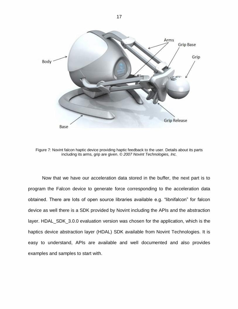
Figure 7: Novint falcon haptic device providing haptic feedback to the user. Details about its parts including its arms, grip are given. © 2007 Novint Technologies, Inc. ................................................................................................................... 17
Figure 8: HDAL (Haptic Device Abstraction Layer) Layered Architecture. This picture is taken from HDAL Programmers Guide provided by Novint Technologies, Inc. 18
Figure 9: ADXL335 triple-axis accelerometer from Analog Devices .............................. 22
Figure 10: Functional Block Diagram ............................................................................ 22
Figure 11: This is the 2.4GHz XBee 2mW series 2.5 chip antenna. .............................. 23
Figure 12: XBee Explorer USB to connect the XBee modules to the PC. Left side picture indicate the USB explorer and right side indicates the explorer with XBee module and USB cable. .................................................................................... 24
Figure 13: X-CTU software utility is a windows-based utility from Digi International for configuration and upgrade of firmware, and testing of Digi‟s RF products like XBee................................................................................................................. 25

viii
Figure 14: XBee Wireless Shield for interfacing XBee module with the ADXL335 accelerometer. .................................................................................................. 27
Figure 15: The Schematic Diagram of “XBee Accelerometer Module” showing the interfacing between ADXL335 and XBee. ........................................................ 29
Figure 16: The completely developed “XBee Accelerometer Module” consisting of the XBee and ADXL335 interfaced on the XBee Shield with appropriate voltage regulation, and 9v battery as a power supply. .................................................. 30
Figure 17: ZigBee IO Data Sample Rx Indicator frame pattern transmitted in this application. ....................................................................................................... 32
Figure 18: The conventional three degree-of-freedom joystick used to control the ODIS. ......................................................................................................................... 35
Figure 19: FreeWave 900 MHz board radio with its interface cable, which is connected to the serial to USB connector, connecting the USB serial of the computer. .... 36
Figure 20: ODIS packet structure provided by TARDEC. Picture used with the permission of Shawn Hunt [1]. .......................................................................... 37
Figure 21: Absolute Hardware Architecture Design of the tele-operation system showing all the components and the wireless networks involved. .................................. 42
Figure 22: Absolute teleoperation system in the CARES lab. Left side showing the server with the Falcon haptic device, XBee server module and Freewave radio attached and right side shows the ODIS robot with XBee accelerometer on the top. ................................................................................................................... 44
Figure 23: Testbed for terrain detection test showing floor mats and a wire shelf which the ODIS was ran over. .................................................................................... 44
Figure 24: Graph showing the total number of users per terrain pattern v/s number of users successfully detected the pattern. M1 = smooth surface mat, M2 = grassy surface mat, M3 = rocky pattern mat, M4 = wire shelf, M5 = floor tile. ............. 47
Figure 25: A subject performing terrain detection test on grassy surface mat. .............. 48
1
CHAPTER 1: BACKGROUND AND SIGNIFICANCE
1.1 Background
This thesis project underlines the development of hardware and software
architecture in the field of tele-operation of mobile robots with force-feedback
capabilities. Tele-operation of mobile robots is often used to perform complex tasks in
hazardous environments: some examples include vehicle inspections [1], inspection of
underwater structures [2], de-mining operations [3], or cleaning nuclear plants [4].
Generally, the task of mobile robots is to inspect vehicles at traffic control checkpoints
e.g. border crossings and security checkpoints. Also, tasks like inspection and
exploration of dangerous environments in military and desert areas are becoming more
relevant. The tele-operator often gets only the visual information and in many cases it is
insufficient to carry out such complex tasks because of restricted visual coverage of
cameras [5]. Haptics is still in its preliminary research phase. Therefore, modern tele-
operation systems are trying to take into account audio and haptic information in
addition to visual data to provide additional feedback to the remote operator.
The meaning of haptics is based on the sense of touch. The word “haptic” is
ingrained in Greek (hapto, to fasten or bind), and refers to the sensation of touch or feel
using a particular device that is either grasped, as a grip, or worn, as a glove. Most of
the haptic feedback systems are used with computer entertainment systems such as
video games. The virtual environment consists of force magnitude and direction
information which is ultimately applied to the user, depending on the position and

2
velocity of the cursor in the environment. It‟s a tactile feedback technology which takes
benefit of human‟s sense of touch by applying forces, vibrations, and/or motions to the
user. This reflex stimulation can be used to assist the enhancement of remote tele-
operation of devices.
1.2 Motivation
Tele-operation is frequently used for controlling mobile robots in unknown and
unstructured environments [18]. The majority of vehicle tele-operation (air, ground, and
underwater) research has significance on rate-control systems for hazardous
environments. User interfaces for remote operation have stayed the same during the
past fifty years. In almost all tele-operation systems, a trained tele-operator controls
remote vehicle‟s translation and rotation with the help of hand-controllers while getting
feedback from multiple video and data displays. Such tele-operation systems can be
difficult to use (especially in unknown, unstructured and hazardous environments),
costly to manufacture, time consuming to set up, and require significant training [19].
Additionally, remote driving becomes challenging often because of loss of
environmental awareness, poor trough and terrain judgment, insufficient perception of
the remote environment and failure to detect obstructions are common consequences
[19]. Navigation in dynamic environments of mobile robots like Omni-Directional
Inspection System (ODIS) which translate at high-speeds, it is often desirable to provide
a sensor-based collision detection method on-board the robot to promise safe
navigation. A dedicated tele-operator is not able to perform multiple tasks and
controlling the ground vehicle can be problematic when the terrain is rough or
communications are degraded [20].
3
Recently, in modern tele-operation systems, multi-modal operator interfaces
including haptic interface is typically used as an additional gesture to assist the user in
understanding the remote environment [13, 14, 15, 16, 17]. Haptic displays are being
progressively more used for applications including art, medical training, and virtual
environments as well [21, 22].
The motivation behind this work was to provide a cost-effective solution for
adding values to the tele-operation capabilities of the system by introducing haptic
interfaces to overcome the problems tele-operators have to face to perceive and
evaluate the remote environment. Also, there is a need to include alternative interfaces
for the user to make the tele-operation easier and more productive in case of unknown
environments having rough terrains or degraded communications. An additional
feedback is needed when the feedback from the camera view and coverage is
insufficient for the user to perform complex tasks and give better idea and feel of the
remote environment.
1.3 Significance and related work
The objective of this research is to develop a robotic tele-operation system
extending the hardware and software architecture to provide the operator with haptic
capabilities. These capabilities will enable the user to perform a widespread exploration
and investigation of dangerous environments in military and desert areas whilst
examining from a safe operating distance. This research focuses on enhancing user
performance in manual tasks by implementing force feedback technology.

4
According to L. Rosenberg, and S. Brave [7], adding both active and passive
force feedback for the completion of tasks decreases task completion times, therefore
increasing user performance. The motivation of this study was to assist persons with
neuromotor disabilities to interact with GUI based computer systems. Active forces are
the forces applied by adding energy into the system whereas in passive force feedback,
forces are applied by removing energy from the system. Controllers using servo motors
are active controllers, and friction brake or magnetic particle break can be categorized
as passive controllers as they dissipate energy from the system. Figure 1 indicates the
results comparing the task completion times in seconds with no force feedback and
applying active and passive forces as feedback to the user from the Rosenberg paper
[7]. Potentially, our research work can also help in assisting persons with such kind of
disabilities. A study by Rosenberg shows that force feedback can enhance the
performance in tele-operation systems as well as in virtual environments [8].
Figure 1: Results of [7] indicating performance times in seconds for completing each targeting tasks.
The robotic unmanned ground vehicle for this research is the Omni-Directional
Inspection System (ODIS). This research is also significant because the basic hardware
and software architecture can be used for not only the underlined ODIS platform, but for
any other unmanned ground vehicle platform. Specifically, the hardware involved is

5
platform independent and can be implemented for many different platforms of
unmanned ground vehicle research.
Robotic systems like the ODIS are used where there is a risk to an operator.
Figure 2 shows an area in Baghdad, Iraq known as Assassin‟s Gate. Left scene in the
figure was captured on 15th March 2004. Right scene is after a car bomb exploded two
months later. The main idea behind this thesis is to develop architecture to expand the
potential of surveillance type robots in terms of stronger tele-operation capabilities
giving more information back to the operator about the environment at a safe operating
distance.
Figure 2: This is Assassin‟s Gate, an area in Iraq. Left scene captured in March 2004 and right scene of the same area after two months with car bomb explosion. Picture used with permission of Shawn Hunt
[1].

6
How does one give more information about the environment back to the
operator? The use of sensors which can capture critical data at the remote site and
provide high level information to the user is critical. For instance, a user can interact
with a specialized force feedback joystick which can provide haptic information to the
user. Sensors such as accelerometers, odometers, gyroscopes, force sensors,
magnetic compasses, and global positioning systems are considered. Borenstein et al.
[9] provide the brief explanation of the characteristics of sensors and positioning
systems for mobile robots. There are seven categories of sensor systems for positioning
of the mobile robots described in this paper -- odometry, inertial navigation, magnetic
compasses, GPS etc. After considering the characteristics of different kind of sensors,
accelerometer sensor gives the most appropriate usability for our application as it can
give a system-level input for force feedback.
There has been a lot of research on designing haptics tele-operation systems.
Additional force feedback to the tele-operator improves the tele-operation performance
as per studies in [10]. It‟s an experiment involving remote control of a mini-rover
MERLIN-car over the internet. It uses hall sensor odometers for distance measurement.
A force sensor implemented at the front of the car serves the purpose of providing force
feedback to the user applying torque to the motors in the force feedback joystick. Also,
when the user is not touching the joystick, the control algorithm keeps the joystick in the
center. A test run of the system where the robot is made to push the box placed on the
floor is performed. The force was felt increasing until the box was moved when the force
was felt decreasing. Results indicate a delay of 35ms is noticed for one data package
cycle from server to the car and back. The relationship between measured force on the

7
car, and applied torque on the joystick is shown. The study concluded that mobile
robots can be controlled effectively with the help of haptic interfaces.
The haptic feedback system in [11] proved to reduce the learning time required to
develop the ability to remotely control the vehicle accurately. The system discussed in
the paper remotely pilots the aerial vehicle using haptic force feedback. This system,
unlike other systems uses existing off-the-shelf motion capture (MoCap) systems for
position tracking for closed-loop movement control. The vehicle motion data is then
used as feedback and provided to the haptic controller joystick. The high resolution
cameras determine the 3D position of passive retro reflective markers positioned on the
parts of vehicle. This paper also involves real-time 3D simulated modeling. This study
elaborates on a haptic feedback system which provides a quick response and precise
control. Tele-operation which allows the user to feel as if he is controlling the vehicle by
direct handling was implemented. To conclude, this study provided more natural haptic
interface for vehicle position control which extended precise control abilities to the pilots.
1.4 Advantages of using accelerometer sensor
Studies mentioned above have used odometer sensors and Motion Capture
systems for direction & orientation which does not provide trough & terrain information
to the user. Also, force sensors used in [10] which help to provide force feedback have
limitations. For instance, these sensors can detect the force applied only in that
particular direction and again would not be sufficient to provide the terrain information. It
can be used for collision detection only in that particular direction. Hence, force sensors
are totally dependent on their position on the robot and the direction of collision or
impact. So, it‟s not efficient to use the force sensor for sensing terrain as we will have to

8
use multiple sensors in all possible directions. An accelerometer, on the other hand is
independent of its placement on the robot and direction of impact. So, no matter where
the robot hits the obstacle or goes over a hump, an accelerometer will detect the
change in acceleration in the particular direction.
Accelerometer sensor can give a good input for force-feedback, because force is
directly proportional to acceleration. Hence, it is hypothesized that an accelerometer
can give a better feel of the terrain the robot is going over and also that this information
will be useful for exploring areas especially in dangerous environments such as military
applications.
1.5 Research plan - System Architecture
The ultimate goal of the robotic system is to provide the operator with haptic
information in addition to the video data to perform a widespread exploration and
investigation of dangerous environments whilst examining from a safe operating
distance. ODIS was originally developed by the Center for Self-organizing and
Intelligent Systems at Utah State University under a contract with the Army [1]. ODIS
has the capability to translate in all directions and simultaneously rotate. The basic
ODIS platform has a video camera with tilt capabilities (Figure 3). The ODIS is on loan
to WSU from TARDEC.

9
Figure 3: Front view of ODIS, Omni-Directional Inspection System.
The description of the first version of ODIS and its hardware is described in [6]. It
comprises of two RF links, one connected to a user joystick and another communicates
with a path planner. The ODIS was also equipped with a combination of a Global
Positioning System, gyroscope unit, optical wheel encoders, sonar, infrared, and laser
sensors. Some intelligent behaviors might be available on the ODIS model but there is
no known documentation available. Therefore, in [1], it was chosen to add hardware
and create a software framework to extend the original design to allow other
applications, rather than attempting to decode the firmware commands.
10
The hardware to extend the architecture with force feedback capabilities is a
force feedback joystick, the Novint Falcon Haptic Device. It is a 3-DOF haptic device
developed for the gaming industry. The Falcon controller is essentially a robot having 3
arms moving right - left, forwards - backwards, like a mouse, and also moves up and
down, giving third degree of freedom. When you hold the Falcon‟s attachable grip and
move the cursor to interact with an environment, virtual object, or character, motors in
the device turn on and are updated approximately 1000 times a second.
The research plan of the thesis emphasizes on the expansion of the
hardware/software system architecture to engross haptics tele-operation of the ODIS.
The architecture mainly focuses here on the ODIS but can be used on any unmanned
ground vehicle. The new expanded tele-operation system consists of haptic joystick
control with haptic feedback mechanism, client/server software framework, collision
detection and terrain detection. The complete closed-loop feedback system architecture
is shown in Figure 4.
The ODIS is remotely operated with the Novint falcon joystick connected via a
server. The direction of motion can be given from the joystick which is then
communicated further by the server via a 900 MHz radio made by FreeWave
Technologies. The software framework writes on the serial port the command
movement translated from the Novint joystick to the server. The Freewave radio is
connected through USB/serial port to the server which communicates with the ODIS.
ODIS, on the other hand is equipped with small hardware circuitry – XBee
accelerometer module placed on the top. XBee accelerometer module wirelessly
transmits the acceleration data to the XBee server module (connected on the server

11
through USB/serial port). The server module receives the frame containing the
acceleration data from XBee accelerometer module. The software framework then
extracts the data from serial port, manipulates, and translates the proper format of the
acceleration data to the Novint falcon joystick. The user feels the force feedback as a
result.
Figure 4: This is the Expanded System Architecture which describes the research plan of the thesis. The new tele-operation of ODIS contains joystick control and haptic feedback mechanism, client/server
software framework, collision detection and terrain detection.
This research work is segregated into two specific aims as follows:
Aim 1: Create a testbed for haptic tele-operation
a) Implement Accelerometer sensor on the top of ODIS.
b) Get the force-feedback on the Novint Falcon joystick.
c) Give directions to ODIS using Novint Falcon joystick.
12
• Aim 2: Execute a performance evaluation of the impact of haptic tele-operation
a) Perform a user study which determines if the user can detect surface
terrain and bumps/pot holes in the path.

13
CHAPTER 2: ACCELEROMETER SENSOR INTEGRATION WITH A FORCE FEEDBACK JOYSTICK
2.1 Overview
This chapter provides details of the work done for assessing the accelerometer
sensor. The groundwork is done to provide a good proof of concept of using the
accelerometer sensor for providing the force feedback to the joystick.
2.2 Accelerometer sensor
To begin with, the “Watchport/A” acceleration sensor from Digi International was
taken into consideration (Figure 5). The dual-axis acceleration and tilt sensor was
available already in the CARES lab. Watchport/A is a cost-effective plug-and-play USB
device used for 24/7 environment monitoring. These sensors are mainly used with
surveillance cameras for monitoring systems. Users are allowed to use their own
software applications or can also use the included Watchport Manager software.
The sensor represents itself to a user application in the form of virtual serial port.
The application can access the serial port in the form of COMx (standard serial port)
where x can be between 1 and 255. The Watchport/A sensor can be operated in two
types of modes. One mode lets the user use an ASCII command interface whereas
another mode uses an RS-232 modem signal interface.

14
Figure 5: Watchport/A (Acceleration & Tilt Sensor) from Digi International with RJ45 terminated cable. The RJ45 cable connects into corresponding jack on the Watchport base unit.
The ASCII command interface mode was chosen for our application. The set of
ASCII commands available for the Watchport/A sensor are listed in Table 1. All the
ASCII commands sent to the sensor must be terminated with a carriage return character
<CR>. The carriage return character is used as „\r‟ in c++. The table describes the
command and its significance as well as the return value from the sensor. Note that for
the return values of commands A and U in the table, +/- means the value will be either
positive or negative, m.mm and n.nn represent a number to the hundredth decimal, g
stands for gravitational value, and X for the x axis and Y for the y axis.
Before starting, it is always recommended to calibrate the sensor. Place the
sensor at its “neutral position”. Calibrate the sensor using C command to establish its
“neutral position”. The return value will be ok. Finally verify for correct calibration using
A command. The return value will be +0.00gX +0.00gY. The acceleration range

15
provided is from: -2g to 2g, where g is in terms of gravity. In the application, the
commands are used to write to the serial port and the return value is read from the
serial port.
Command Description Return Value
?<CR> Tells about the command set available for this Watchport. All commands here.
I<CR> Tells what kind of Watchport is connected. Watchport/A<CR>
C<CR> Calibrates the sensor. OK<CR>
A<CR> Returns the current acceleration. +/-m.mmgX
+/-n.nngY<CR>
U<CR> Reads the raw axis values i.e. the values if C command
were never executed.
+/-m.mmgX
+/-n.nngY<CR>
E<CR> Switches to modem signal mode. OK<CR>
Mn<CR> Adjusts sensitivity. N = 1 (most sensitive) through 9. OK<CR>
Table 1: Description of ASCII command set available for Watchport/A sensor with the return value.
To communicate with the sensor via a virtual serial port, the c++ code uses the
serial class written by Shawn Hunt [1] which abstracts the details of serial
communication. It is based mainly on the serial library developed by Ramon de Klein
[12]. More details on calibration command is provided in Appendix D.
Figure 6 shows the acceleration data output when read from the accelerometer.
As seen from the output values, the acceleration changes in both x and y axis which
indicates the accelerometer moved in both x and y direction. Now, we have the
acceleration value on x-axis and y-axis in terms of gravitation in the buffer. These

16
acceleration values have to be extracted from the buffer and should be provided as an
input for force in proper scaled format correspondingly to the x and y direction of the
falcon joystick. If the user can feel the force feedback on the falcon joystick, this work
provides the proof of concept for usability of the accelerometer for force feedback.
Figure 6: Acceleration data return value from the Watchport sensor in x and y-axis in terms of g.
2.3 Novint Falcon Haptic device and SDK
Falcon joystick is a 3-DOF haptic device made by Novint technologies for the
gaming industry (Figure 7). The detachable grip is attached to the grip base. There are
other grips available as well for gaming purposes e.g. pistol grip but we preferred the
ball-grip. The body consists of three Mabuchi RS-555PH-15280 motors whose motion
can be monitored by a coaxial 4-state encoder. All three arms are connected to the
motors inside the body of the device. It connects to the PC via USB port.
17
Figure 7: Novint falcon haptic device providing haptic feedback to the user. Details about its parts including its arms, grip are given. © 2007 Novint Technologies, Inc.
Now that we have our acceleration data stored in the buffer, the next part is to
program the Falcon device to generate force corresponding to the acceleration data
obtained. There are lots of open source libraries available e.g. “libnifalcon” for falcon
device as well there is a SDK provided by Novint including the APIs and the abstraction
layer. HDAL_SDK_3.0.0 evaluation version was chosen for the application, which is the
haptics device abstraction layer (HDAL) SDK available from Novint Technologies. It is
easy to understand, APIs are available and well documented and also provides
examples and samples to start with.

18
The main aim of HDAL is to offer a uniform interface to all supported device
types. The APIs provided are used for selecting a device, initializing it, reading its state
(position, buttons, etc.), issuing force commands to it, and shutting it down properly.
HDAL is implemented as a sequence of layers (Figure 8). The application layer contains
the haptic simulation component, which indicates what the user should feel as a haptic
feedback. The application communicates with HDAL through the HDAL API, and the
main building block of that communication, after initialization, is via the callback
function. The function is called from within HDAL once every servo “tick”, approximately
1,000 times per second. In this function, the user reads the servo position, calculates
the forces, and sends the forces to the device. In this particular application, which we
are discussing, the forces are calculated in the callback function using the acceleration
data, which comes from the application.
Figure 8: HDAL (Haptic Device Abstraction Layer) Layered Architecture. This picture is taken from HDAL Programmers Guide provided by Novint Technologies, Inc.
19
The abstraction layer handles a family of drivers, one for every type of device
known to HDAL. The primary driver, in this application is for the Novint Falcon. The
HDAL driver layer knows how to communicate with the device SDK to provide all the
functionality provided by the application. The SDK, in turn, has to communicate with the
actual device. This communication here is via USB. The initialization sequence for the
Falcon device is provided in Appendix E.
The basic example provided with the SDK, named “basic_opengl” is used to get
familiarized with the SDK APIs, and the implementation of the callback function. The
acceleration data from the accelerometer is read from the serial port as an ASCII string
and stored in a buffer. The buffer keeps on updating the new values. The buffer values
are in turn stored in char type variable. Now, it needs to be converted into a proper
format to provide the actual acceleration value which can represent the force on the
joystick. So the char type variable is converted first into double type, The value is then
scaled according to the force values. The acceleration value range from -2g to +2g
whereas the force value ranges from -3 to +3 Newton. The function “hdlSetToolForce” is
used to set the tool forces. This function is implemented inside the servo callback
function.
This preliminary work connecting the Watchport/A accelerometer and Novint
Falcon joystick on the PC accomplishes its goal of proving the concept of using the
accelerometer to provide the force feedback to the joystick. This work provides the user
with the force feedback in accordance with the accelerometer. So if the accelerometer is
moved in the positive x direction, the user feels the force on the joystick in the positive x
direction.

20
CHAPTER 3: IMPLEMENTING THE ACCELEROMETER SENSOR CIRCUITRY ON ODIS
3.1 Overview
As discussed in the previous chapter, the preliminary work has proved that it is
feasible to use accelerometer to give the force feedback. But, there are some
disadvantages of using the Watchport/A sensor in this application. This chapter
describes the drawbacks and limitations of using the Watchport/A sensor for the
application, and the details of the hardware sensor circuitry developed for the
architecture are discussed. The sensor circuitry is implemented in order to read the
acceleration data when it is placed on the ODIS. Constraints like wireless capability of
the sensor, size of the circuitry and its robustness are considered in the implementation.
3.2 Limitations of Watchport/A sensor
First of all, Watchport/A sensor is a dual axis acceleration sensor, which restricts
its ability to provide the terrain or trough information. This proves the inefficiency and
incapability of the sensor. It has a USB interface to connect and needs a wireless router
to be attached along with the Anywhere USB (Digi international) [1]. All the extra
equipments will require power as well. All equipments together with power supply
counts for the size constraint along with the wireless capability of the sensor. Also, the
Watchport sensor when used provides a low frequency output. Hence, it would not be
updated as frequent as the Novint joystick can, which will affect the performance of the
system.

21
3.3 Wireless accelerometer circuitry
Now, as it was clear that a sensor like Watchport/A was not efficient for this
particular application, it was decided to look for an accelerometer which can provide 3-
axis acceleration output with better frequency. Also, it should provide the output
wirelessly, by itself or by interfacing with other circuitry. The wireless accelerometers
available in the market were either costly or had range constraints (having short
operating range e.g. Bluetooth).
It was decided to use the accelerometer ADXL335 from Analog Devices along
with XBee 2mW series 2.5 chip antenna to provide the wireless capability. The
ADXL335 is a small, cost sensitive, thin, low power, complete 3-axis accelerometer
(Figure 9). It measures acceleration with a minimum full scale range from -3g to +3g. It
can measure dynamic acceleration resulting from motion, shock, or vibration which
makes it easier to provide the terrain information. There is no on-board power. Provided
power should be between 1.8 and 3.6VDC. The included 0.1uF capacitors, as shown in
the block diagram in Figure 10, set the frequency of each axis to 50Hz. The block
diagram represents fully assembled board with all the components installed.

22
Figure 9: ADXL335 triple-axis accelerometer from Analog Devices
The bandwidth of the accelerometer can be selected by using Cx, Cy, and Cz
capacitors at the output pins XOUT, YOUT, ZOUT (Figure 10). Bandwidth range can vary
from 0.5 Hz to 1600 Hz for the X and Y axes, and a range of 0.5 Hz to 550 Hz for Z
axis. For this application, we have used the included 0.1uF capacitors on board as it
provides 50 Hz output per axis which is sufficient for the system.
Figure 10: Functional Block Diagram

23
XBee series 2.5 modules from Digi international, as shown in Figure 11, are used
for wireless data transfer. Two of such XBee transceiver modules are introduced in the
system, one on the accelerometer circuitry on the ODIS which will transmit the
acceleration data wirelessly and another on the server side capturing the data.
Figure 11: This is the 2.4GHz XBee 2mW series 2.5 chip antenna.
XBee modules are the family of embedded RF modules providing both 2.4GHz
and 900MHz solutions. We used 2.4GHz XBee modules for this application. These
modules acquire the 802.15.4 stack (the basis for Zigbee) and wrap it into an easy to
use serial command set. XBee modules allow a very reliable and simple communication
between microcontrollers, systems, computers, or anything with a serial port. It supports
point-to-point as well as multi-point networks.
For the XBee modules to behave as a transmitter on the sensor side and as a
receiver on the server side, it needs to be configured and firmware upgraded. To

24
connect the XBee modules to the PC, XBee Explorer USB is used. Figure 12 shows the
XBee Explorer USB, which works with all the XBee modules to give direct access to the
serial and programming pins on the XBee unit.
Figure 12: XBee Explorer USB to connect the XBee modules to the PC. Left side picture indicate the USB explorer and right side indicates the explorer with XBee module and USB cable.
To do the firmware configuration and upgrade, “X-CTU” – Configuration and test
utility software from Digi International is used. Figure 13 shows the windows-based GUI
of the X-CTU software. “PC Settings” tab shows the COM ports where the products are
connected (usually connected via USB) and allows the user to select the desired COM
port and configure the port for the radios settings. ”Range Test” tab allows the user to
perform a range test between two radios. ”Terminal” tab allows accessing the COM port
with a terminal emulation program. This tab also allows the ability to access the
firmware of the radio using AT commands, discussed later. “Modem Configuration” tab
provides the ability to program the radios‟ firmware settings via GUI and drop-down
menus. Also, the ability to change the firmware versions is allowed in this tab.

25
Figure 13: X-CTU software utility is a windows-based utility from Digi International for configuration and upgrade of firmware, and testing of Digi‟s RF products like XBee.
To start with, the XBee server module to capture the acceleration data is plugged
into the USB explorer and connected to PC for the configuration and upgrade of the
firmware. X-CTU software is used to select the appropriate USB com port is made. In
modem configuration, click on read will show which XBee type is connected and which
firmware is currently on the device. From the Modem pull down list, XB24-ZB is selected
and Function set “ZIGBEE COORDINATOR API” is selected. The firmware version
“2270” is selected. API mode is required to receive analog/digital data from ADC pin of
a remote radio (XBee connected to accelerometer, here). Under “Addressing”, the NI

26
(node identifier) is named as “JOYSTICK”. Under “Serial interfacing”, the “baud rate” is
selected as 115200kbps.
Now, the XBee module which will be hooked to the accelerometer is plugged into
the USB explorer and connected to the PC for the configuration and upgrade of the
firmware. In X-CTU software, from the Modem pull down list, XB24-ZB is selected and
Function set “ZIGBEE ROUTER AT” is selected. The firmware version “2270” is
selected. Under “Addressing”, the NI (node identifier) is named as
“ACCELEROMETER”. Under “Serial interfacing”, the “baud rate” is selected as
115200kbps. In the “I/O settings”, the DIO0, DIO1, and DIO2 is configured as 2-ADC.
These input/output pins will be used to read the values from all the three axes from the
accelerometer. Also, in the “I/O settings”, IR (input sample rate) is changed to 32 (hex
value for 50 milliseconds). The entire configuration settings with the firmware upgrade
are written to the device by clicking on “write” button. Now, on the “Terminal” tab, to
enter command mode on the XBee module, "+++" command (without pressing enter) is
sent. It responds with "OK". Next "ATDNJOYSTICK" command is sent. It responds with
"OK". This sets the destination node to another XBee module – “JOYSTICK” module.
Next, "ATWR" command is sent which will write the settings to the memory so that the
settings are not lost when the XBee is powered off. The terminal window with command
looks as following:
+++OK
ATDNJOYSTICK
OK

27
ATWR
OK
Now, both the “accelerometer XBee” and “joystick XBee” are configured and
updated. “Joystick XBee” directly connects to the server via USB port using the XBee
USB explorer.” Accelerometer XBee” needs to be connected properly to the pins of
ADXL335 accelerometer. For this task, XBee Wireless Shield is used for interfacing
XBee with ADXL335. The XBee Shield simplifies the task of interfacing an XBee with
any sensor device or other controller. This board assists directly with a USB board, and
equips it with wireless communication capabilities using the popular XBee module.
Figure 14 shows the XBee Wireless Shield.
Figure 14: XBee Wireless Shield for interfacing XBee module with the ADXL335 accelerometer.
28
The shield also takes care of level shifting on the DIN pin of the XBee. The board
includes LEDs to indicate power and activity on DIN, DOUT, RSSI, and DIO5 pins of the
XBee, and a 12x11 grid of 0.1" holes are available for prototyping, which is used to
connect the accelerometer circuitry. In the architecture, the “XBee Accelerometer
Module”, as mentioned in Figure 4, consists of the XBee Shield with XBee and
ADXL335 interfaced. This Shield goes on the top of ODIS.
A 9V power supply (battery) is connected to give power to the circuitry. Power on
board is taken from the 5V pin and regulated on-board to 3.3VDC before being supplied
to the XBee. Therefore, a positive voltage regulator needs to be used to regulate the
power to 5V. A three-terminal positive 5V voltage regulator - L7805C is used with an
output voltage of 5V and output current up to 1.5A.
Finally, XBee and ADXL335 are hooked up. Both are powered by 3.3V power
with the help of L7805C voltage regulator and on-board power regulation. But, the XBee
ADC pins can only accept voltages in the range of 0 - 1.2V and the output X, Y, and Z
acceleration from ADXL335 is in the range of 0 - 3.3V (max). So, voltage dividers need
to be added on the X, Y and Z axes output acceleration. The schematic of the “XBee
Accelerometer Module” is shown in Figure 15. As seen from the schematic, XOUT, YOUT,
and ZOUT of ADXL335 are connected to DIO0, DIO1, and DIO2 pins of the XBee
respectively with voltage dividers for each connection. Voltage dividers use the
combination of 6.1K and 3.5K resistors.

29
Figure 15: The Schematic Diagram of “XBee Accelerometer Module” showing the interfacing between ADXL335 and XBee.
The complete “XBee Accelerometer Module” with XBee being placed on board,
ADXL335, a voltage regulator L7805C, and voltage divider resistor pairs for all the three
axes soldered, powered by 9V battery can be seen in Figure 16. This Module can now
be placed or attached on the top of the ODIS, which will measure the acceleration data
and send it wirelessly to the “XBee Server module” connected on the server via USB
explorer.
This concludes the aim 1(a), of implementing accelerometer sensor circuitry on
the top of ODIS. Next aim would be to get the force feedback on the Novint Falcon
device taking into consideration the accelerometer sensor circuitry designed.

30
Figure 16: The completely developed “XBee Accelerometer Module” consisting of the XBee and ADXL335 interfaced on the XBee Shield with appropriate voltage regulation, and 9v battery as a power
supply.

31
CHAPTER 4: FORCE FEEDBACK INTEGRATION AND TELE-OPERATION
4.1 Overview
This chapter covers the main aim of teleoperating the ODIS which involves
getting the force feedback from the wireless accelerometer sensor circuitry discussed in
the previous chapter as well as driving the ODIS with the help of Novint Falcon device
simultaneously. This chapter also explains the final design of software and hardware
architecture of the system.
4.2 Force feedback from “XBee Accelerometer Module”
The “XBee Accelerometer Module” sends the acceleration data to the “XBee
Server Module”, which can be observed as a serial device on the server. The data
transmitted from the “XBee Accelerometer Module” is in the form of API packets over
the XBee's UART, to the FTDI chip, to the XBee Server Module‟s USB-serial device.
The API packet specification from the XBee 2.5 manual indicates that in this application,
ZigBee IO Data Sample Rx Indicator frame type is transmitted. The X, Y and Z axis
acceleration data on DIO0, DIO1 and DIO2 has to be transmitted wirelessly from the
“XBee Accelerometer Module” to the server respectively.
When the server module receives an IO sample frame from accelerometer
module, it sends the sample out the UART using the frame type shown in Figure 17.

32
Figure 17: ZigBee IO Data Sample Rx Indicator frame pattern transmitted in this application.
The frame starts with the start delimiter 0X7E. The length field has two-byte
value that denotes the number of bytes that will be contained in the frame data field. It
does not include the checksum field. The Frame data of the UART data frame forms an
API-specific structure containing API Identifier and Identifier specific data. In IO data
sample Rx indicator frame pattern, the API identifier value is 0x92. At last, to test data
integrity, a checksum is calculated and verified.
Now, the identifier specific data consists of eight fields for IO sample frame. This
contains:
1. 64-bit address (Bytes 5 -12), MSB (most significant byte) first.
2. 16-bit network address (Bytes 13-14), MSB first.
3. Receive options (Byte 15), 0x01 – packet acknowledged and 0x02 –
packet was broadcasted.
4. Num Samples (Byte 16), number of sample sets included in the payload.
5. Digital Channel Mask (Bytes 17-18), bitmask field indicating which digital
IO lines on the remote side, has sampling enabled.
33
6. Analog Channel Mask (Byte 19), bitmask field indicating which analog IO
lines on the remote side, has sampling enabled.
7. Digital Samples (Byte 20, 21), if the sample set includes any digital IO
lines (Digital Channel Mask > 0), these two bytes contain samples for all
enabled digital inputs.
8. Analog Samples (2 Bytes each sample), if the sample set includes any
analog input lines (Analog Channel Mask > 0), each enabled analog input
returns a 2-byte value indicating the A/D measurement of that input.
Analog samples are ordered sequentially from AD0/DIO0 to AD3/DIO3, to
the supply voltage.
In this application, the software architecture takes care of extracting the value of
the analog samples (from DIO0 to DIO2) from the IO data frame pattern received at the
server, and then converting the voltage values to the acceleration value. The software
reads the serial port, observes the frame pattern, stores the frames in buffer, then looks
for the start delimiter. Once, the start delimiter is known, it is easy to know the value of
analog samples, which are then converted in acceleration values by the software.
Once, the acceleration values are calculated, it‟s the same method to set the tool
force as discussed in the preliminary work. The difference here is the acceleration data
is captured by the “XBee Accelerometer Module” which is much more efficient and
prominent than the previous one discussed for the application. The function
“hdlSetToolForce” is used to set the tool forces. This function is implemented inside the
servo callback function, which is called every servo tick. The forces in the X, Y and Z

34
direction are applied according to the acceleration values captured from the
accelerometer in the respective axes.
With the end of this section, the aim 1(b) of getting the force feedback from the
designed sensor circuitry is achieved. Next aim would be to give directions to the ODIS
using the Novint falcon joystick, which is discussed in the next section.
4.3 Direct the ODIS using Novint Falcon
The task of directing the ODIS using Novint Falcon is principally based on the
preliminary work done by Shawn Hunt [1], who proposed the I/O overlapped structure or
framework to control the ODIS by giving commands from the computer rather than
using the conventional three-degree of freedom joystick (Figure 18). The red and green
buttons on the front are used to turn the power on and off on the conventional joystick.
The operator puts on a backpack with a video display mounted where he can
view the current video from ODIS. The joystick can be held by the operator where he
can control its movement. As discussed in [1], there is no access provided to the
proprietary libraries used in the development of the control software in ODIS, so the
existing software can‟t be recompiled or new software can‟t be added to ODIS‟
processor. It was proposed to share the existing communications within ODIS
implementing a new software framework.
35
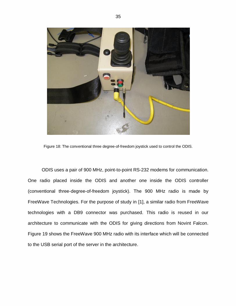
Figure 18: The conventional three degree-of-freedom joystick used to control the ODIS.
ODIS uses a pair of 900 MHz, point-to-point RS-232 modems for communication.
One radio placed inside the ODIS and another one inside the ODIS controller
(conventional three-degree-of-freedom joystick). The 900 MHz radio is made by
FreeWave Technologies. For the purpose of study in [1], a similar radio from FreeWave
technologies with a DB9 connector was purchased. This radio is reused in our
architecture to communicate with the ODIS for giving directions from Novint Falcon.
Figure 19 shows the FreeWave 900 MHz radio with its interface which will be connected
to the USB serial port of the server in the architecture.

36
Figure 19: FreeWave 900 MHz board radio with its interface cable, which is connected to the serial to USB connector, connecting the USB serial of the computer.
The radio had to be configured to be on the same network as ODIS using “EZ-
Config” – configuration software by Freewave. This part was already done in [1], so we
used the already configured FreeWave radio. The mode of the modem was configured
as “Point-to-MultiPoint Master”. The baud rate was configured to 9600 to match that of
ODIS. Other transmission characteristics were also set to match ODIS.
In [1], the remote computer sends a valid ODIS command via the radio and the
message is executed by ODIS. The commands were sent by the framework in the study
using Overlapped I/O serial communication. The framework used the structure for an
ODIS packet provided by TARDEC. The structure is shown again here with the
permission of Shawn Hunt (Figure 20). The commands to control movement of ODIS
are passing a value ranging from -3.0 to +3.0 to X Dot, Y Dot, and/or Yaw Dot. X Dot
commanding forward and reverse movement, Y Dot commanding left and right
movement, and Yaw Dot commanding clockwise and counter-clockwise movement.

37
Another field used is “Checksum” which is an eight-bit integer sum over the entire
packet.
Figure 20: ODIS packet structure provided by TARDEC. Picture used with the permission of Shawn Hunt [1].
In our architecture, the joystick is set to send the command movements to the
ODIS. The framework with the ODIS packet structure is added to the proposed software
architecture here, where the joystick movement is set as input for X Dot, Y Dot and Yaw
Dot command movement. For example, if the joystick is moved in positive X direction,
the value of X Dot will be the corresponding positive value and so on. The scaling of the
values is not required because both the ODIS packet and the Novint Falcon joystick
values range from -3 to +3. So, instead of giving command manually from the computer,
38
we enhanced the software in [1] and included the Novint Falcon to send commands to
the ODIS. As discussed earlier, using the callback function from the HDAL, we can read
the servo position, send forces to the device etc. The current tool position is read using
“hdlToolPosition” API.
For the tool position to be consistent and precise, the position needs to be
controlled in a way that if the user is not touching the joystick (holding the grip), it should
remain at its corresponding position. In other words, there should be gravity
compensation control appended in the application, which prevents the joystick arms
from falling down because of gravity, when the user is not holding the grip. Apparently,
the Novint HDAL_SDK_2.1.3 does not support the gravity compensation. But, when
checked about this concern with Novint Technologies, they suggested us to use the
intermediate/evaluation version HDAL_SDK_3.0.0_EVAL provided by Novint.
The evaluation version included many new features e.g. gravity compensation
control, new grip APIs, upgrade of FTDI drivers, smart grip support etc.
Control of gravity compensation is done in a separate file, FalconCommon.txt.
This file is searched for according to the same rules as those used to find HDAL.INI.
HDAL.INI is the master configuration file and is normally found in the config folder of the
pointed to by the NOVINT_DEVICE_SUPPORT environment variable. However, if the
user has not modified the PATH from the normal Novint installation, a “local” copy of
HDAL.INI can be placed in the application executable‟s folder, and it will replace the
normal copy. Similarly, if FalconCommon.txt file exists in the
NOVINT_DEVICE_SUPPORT\config folder, it applies to all applications. But, if there is
39
a FalconCommon.txt file in the application‟s launch folder, the master version is
overridden. The content of the file is only one line: “0 gravity” to turn gravity
compensation off, or “1 gravity” to turn it on.
By default, the gravity compensation is on. Still, we created a FalconCommon.txt
file in the application‟s launch folder named “Debug” containing the line “1 gravity”. This
file is read when the Falcon device is initialized or when the joystick grip is changed.
Camera power on the ODIS camera can also be controlled with the help of any of
the buttons on the Novint Falcon joystick. The API for button status is being used to
check the button status and the information is sent accordingly on the ODIS packet
structure. This helps to control the camera power on the ODIS whenever required. For
example, for rough or bumpy terrain surfaces, the video coming from the ODIS camera
would not be smooth or useful and will not provide useful information in which case the
user can turn the camera power off from the joystick.
With this task, we were now able to direct the ODIS using the Novint Falcon. We
now have a software architecture accommodating the force feedback capability as well
as tele-operation capability of driving the ODIS. We also have a hardware architecture
designed to complete the purpose. This section results in achieving the aim 1(c) of
giving directions to ODIS using Novint falcon joystick.
4.4 Software and Hardware Architecture
At this stage, we are done with specific aim 1 (with its sub-aims) of designing a
testbed for haptic tele-operation. The accelerometer sensor circuitry is developed which
when kept on the ODIS can provide force feedback on the Falcon joystick. We can drive

40
ODIS using Falcon joystick as well. This signifies the development of complete haptic
tele-operation system. This section will explain the comprehensive view of both the
software and hardware architecture developed, inclusive of the components altogether.
The software architecture is written as a c++ code in Microsoft‟s Visual Studio
2005 which includes HDAL library for interaction with the Novint Falcon device, serial
communication for receiving the acceleration data, and overlapped I/O serial
communication for sending the commands for the movement of ODIS integrated in one
single project. All the header and c source files are located in the “src” folder. There are
three header files and four cpp files-
1. “acc.h” – consists of declaration of ODIS packet structure, function prototypes for
initializing ODIS, accelerometer communication, getting accelerometer reading,
and command movement for ODIS etc.
2. “Serial.h” – consists of CSerial class written by Shawn Hunt [1], to abstract the
details of serial communication.
3. “haptics.h” – provided by Novint consists of declaration of Haptics class, call-
back function declaration, handle to device etc.
4. “Acc_ODIS.cpp” – consists of instantiation of ODIS packet structure and CSerial
class for serial communication with XBee as well as FreeWave radio, and
function definitions which were declared in “acc.h”.
5. “Serial.cpp” – consists of methods defined for opening, closing, reading and
writing in the serial port with overlapped and non-overlapped I/O communication.

41
6. “haptics.cpp” – consists of definitions of call-back function, function which
provides forces to the Falcon device according to the acceleration data, function
to get the current position of the tool for command movement, etc.
7. “main_opengl.cpp” – consists of the main loop calling the scene setup function.
Scene setup function calls the ODIS and accelerometer initialization function,
then calls the haptics initialization function.
The hardware architecture design of the tele-operation system (Figure 21) shows
all components as a block along with the two wireless networks being implemented. The
user provides the command movements using Novint Falcon Haptic Device. The
commands are sent through the server via FreeWave radio on the 900 MHz wireless
network to ODIS. ODIS is now equipped with the wireless XBee Accelerometer Module
which sends the acceleration data using the XBee 2.4 GHz wireless network to the
XBee transceiver module attached to the server. The server then calculates the forces
according to the acceleration and gives feedback to the Falcon device which is felt by
the user. The user now is able to teleoperate the ODIS and get the force feedback
simultaneously on the Falcon haptic device.
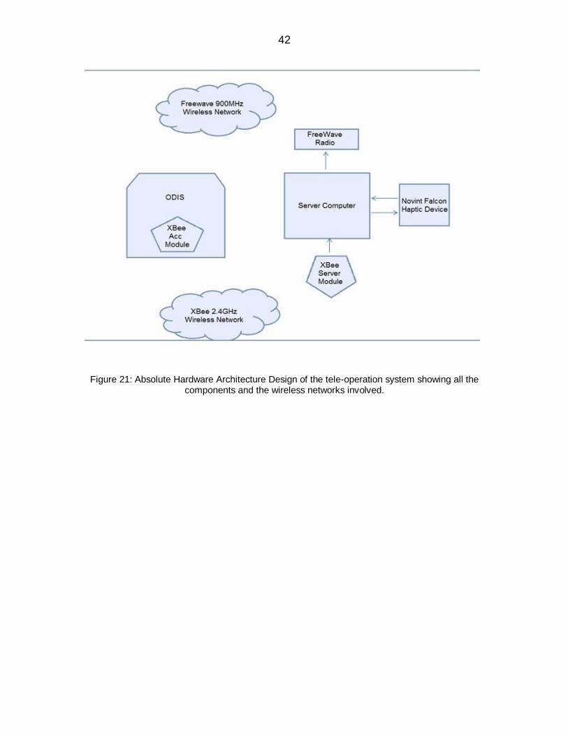
42
Figure 21: Absolute Hardware Architecture Design of the tele-operation system showing all the components and the wireless networks involved.

43
CHAPTER 5: PERFORMANCE EVALUATION AND DISCUSSIONS
5.1 Performance Evaluation
Specific aim 2 of executing a performance evaluation of the impact of haptic tele-
operation is explained in this section. To perform the performance evaluation on the
system designed in this research work, the basic idea was to detect the surface terrain
and bumps/potholes which the robot operated on. Also, collision detection or impact of
the robot with any obstacle in the path is considered.
The tele-operation was restricted to indoor areas. Performance evaluation was
done in the CARES lab. The accelerometer was attached on top of ODIS (Figure 22).
Two types of tests were performed: bump test and terrain detection test. For the bump
test, a wooden plank was put in the path of ODIS which was used as a bump. The user
performed the tele-operation of ODIS using the Falcon device and detected the bump
when the ODIS ran over the wooden plank with no significant delay. There was
significant haptic information observed which gave a better idea to the user the feel of
the environment in addition to the visual feedback.

44
Figure 22: Absolute teleoperation system in the CARES lab. Left side showing the server with the Falcon haptic device, XBee server module and Freewave radio attached and right side shows the ODIS robot
with XBee accelerometer on the top.
For the terrain detection test, a testbed was created (Figure 23). For terrain
patterns, a wire shelf and floor mats were used. Floor mats with varying terrain (grassy
pattern, rocky pattern, or smooth pattern) was used. A wire shelf was used to provide an
uneven wavelike pattern. A subject test involving eight subjects was performed.
Figure 23: Testbed for terrain detection test showing floor mats and a wire shelf which the ODIS was ran over.

45
All the subjects were shown the terrain patterns before performing the test and were
asked to run the ODIS on one of the patterns, unknown to them and to detect the
pattern. They had to detect the pattern within 60 – 80 seconds. No visual feedback was
provided. The testbed was also designed in such a way that the subjects were not able
to see the surface ODIS was traversing on.
Subject Terrain pattern used on testbed Terrain pattern detected by user
1 M1 M1
2 M2 M2
3 M4 M3
4 M5 M1
5 M3 M3
6 M5 M5
7 M4 M4
8 M2 M2
Table 2: Results of terrain detection subject test.

46
Table 2 indicates the results of the subject test where ODIS ran over the top of
different surface materials (M1 through M5) to detect terrain patterns by the tele-
operators. Here M1 = smooth surface mat, M2 = grassy surface mat, M3 = rocky pattern
mat, M4 = wire shelf, M5 = floor tile.
Surface patterns M1 through M4 were known to the users, but floor tile surface
(M5) was kept hidden, in the sense it was used as terrain pattern with some users
without their knowledge. Results show that one of the subjects failed to detect M5 and
detected it as smooth surface pattern (M1) which is very similar to the original pattern.
Also, one of the subjects failed to detect wire shelf (M4) and detected it as rocky surface
(M3) because of similarities between the patterns. Though, if observed and felt closely,
rocky surface pattern provides smoother force-feedback than wire shelf, which allows
the most significant acceleration change due to its structure, providing the most
significant forces among the patterns. Apart from this test, three of the subjects were
asked to tele-operate the ODIS on each pattern available. The subjects were
successfully able to detect the difference between the patterns from the forces felt on
the joystick.

47
Figure 24: Graph showing the total number of users per terrain pattern v/s number of users successfully detected the pattern. M1 = smooth surface mat, M2 = grassy surface mat, M3 = rocky pattern mat, M4 =
wire shelf, M5 = floor tile.
Patterns were chosen randomly for the terrain detection test, so the number
users per terrain pattern were different. Figure 24 shows graph representing the total
number of users per terrain pattern v/s number of users successfully detected the
pattern. Grassy pattern (M2) was detected successfully by maximum number of users
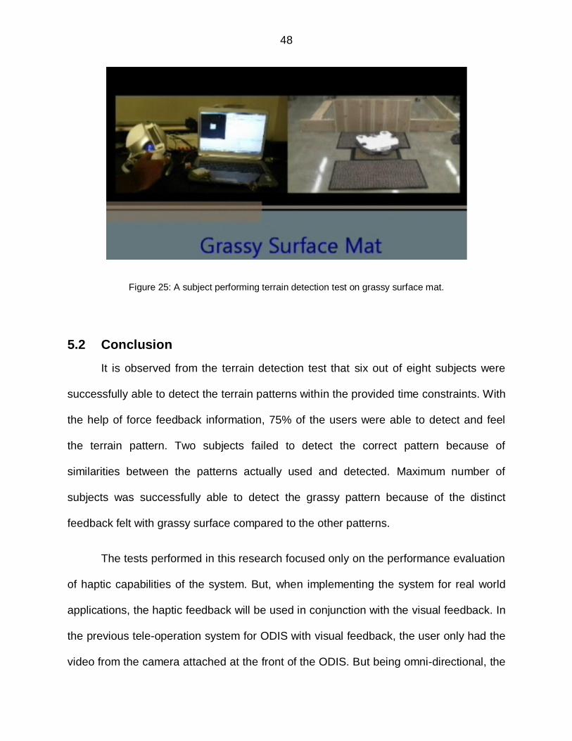
because of its distinctiveness from other terrains. Figure 25 shows a subject performing
terrain detection test on grassy surface mat.
48
Figure 25: A subject performing terrain detection test on grassy surface mat.
5.2 Conclusion
It is observed from the terrain detection test that six out of eight subjects were
successfully able to detect the terrain patterns within the provided time constraints. With
the help of force feedback information, 75% of the users were able to detect and feel
the terrain pattern. Two subjects failed to detect the correct pattern because of
similarities between the patterns actually used and detected. Maximum number of
subjects was successfully able to detect the grassy pattern because of the distinct
feedback felt with grassy surface compared to the other patterns.
The tests performed in this research focused only on the performance evaluation
of haptic capabilities of the system. But, when implementing the system for real world
applications, the haptic feedback will be used in conjunction with the visual feedback. In
the previous tele-operation system for ODIS with visual feedback, the user only had the
video from the camera attached at the front of the ODIS. But being omni-directional, the
49
ODIS has the capability to move in all the directions, even laterally. So, when tele-
operated laterally, the user was not able to get the video information in the direction
robot was moving in. This was the drawback in the conventional tele-operation system.
Using the proposed tele-operation system, the tele-operator would be able to detect the
obstacles and explore the area in all the directions even where the camera view and
coverage is not reachable. Hence, inclusion of haptic information to the user added
value to the tele-operation capabilities of the system. In general, haptic tele-operation
systems add value to the system for similar kind of applications as explained above,
when the visual feedback is insufficient for performing tasks.
5.3 Future discussions
This research has extended the previous work done by Shawn Hunt [1] to
improve the capabilities of ODIS, especially adding haptic sensory capabilities to the
previous conventional tele-operation system. Now, we have the ODIS equipped with the
wireless accelerometer sensor to enhance the tele-operation system with haptic
capabilities. The leverage of the wireless accelerometer system is it can be used not
only with ODIS but with any other unmanned vehicle as well.
The tele-operation system is designed with a modular approach which offers the
system a powerful feature. Also, the system‟s platform independency adds strength to it.
The re-usability of the system allows it to be used with other unmanned ground vehicles
like SRV-1 with great ease. The inclusion of haptic information in the system by
including sensor and haptic device has enhanced the tele-operation capability.

50
Right now, the operating range of the system is around 400ft (120m) because of
the operating range of XBee modules. In the future, it can always be extended by
implementing internet communication from server to another workstation where the
joystick is connected using the client/server software as discussed in [1]. Also, the
methodology discussed in [5] uses the client/server communication for extending the
range of tele-operation.
The system can be enhanced by adding autonomous camera control features.
This feature will move the camera according to the surface terrain or potholes to provide
better visual feedback. It can be done by using the acceleration data to change the
camera tilt angle whenever there is change in particular axis acceleration (particularly z-
axis).
The re-usability feature can be taken advantage of to implement the system on
different unmanned vehicles/ground robots. The architecture can be used in the study of
robotic swarms. Particularly, it can be used for tele-operation of SRV-1 robot which is
used currently in swarm robotics.

51
APPENDIX A: DEVICES/PARTS LIST
Device Name Part Number Manufacturer/Distributer
Novint Falcon Haptic Device None Novint Technologies
Watchport/A sensor 301-1147-01 Digi International
Accelerometer ADXL335 Analog Devices
XBee Series 2.5 Chip Antenna WRL-08691 Digi International
XBee Explorer USB WRL-08687 Sparkfun.com
XBee Wireless Shield WRL-09976 Sparkfun.com
Voltage Regulator L7805C -
900 MHz Radio FGR09CS FreeWave
FreeWave stub antenna EAN900SQ
FreeWave
FreeWave interface cable (DB9 connector)
ASC3640DB FreeWave
FreeWave interface cable (un-terminated wires
ASC3610FL FreeWave
9 Volt Battery - -
12 Volt power supply - -

52
APPENDIX B: PIN CONFIGURATION OF ADXL335
Pin Number Name Description
1 NC No Connect
2 ST Self-Test.
The ST pin controls the self-test feature. When this pin
is set to VS, an electrostatic force is exerted on the
accelerometer beam. The resulting movement of the
beam allows the user to test if the accelerometer is
functional. This ST pin can be left open-circuit or
connected to common (COM) in normal use.
3 COM Common
4 NC No Connect
5 COM Common
6 COM Common
7 COM Common
8 ZOUT Z Channel Output
This is the Z-axis analog voltage output proportional to
acceleration.
9 NC No Connect
10 YOUT Y Channel Output
This is the Y-axis analog voltage output proportional to
acceleration.
11 NC No Connect

53
12 XOUT X Channel Output
This is the X-axis analog voltage output proportional to
acceleration.
13 NC No Connect
14 VS Supply Voltage (1.8V to 3.6V)
15 VS Supply Voltage (1.8V to 3.6V)
16 NC No Connect

54
APPENDIX C: PIN CONFIGURATION OF XBEE 2.5 MODULE
Pin
Number
Name Direction Description
1 VCC - Power Supply
2 DOUT Output UART Data Out
3 DIN Input UART Data In
4 DIO12 Either Digital I/O 12
5 RESET Input Module Reset (reset pulse must be at least 200 ns)
6 PWM0 /
RSSI /
DIO10
Either PWM Output 0 /
RX Signal Strength Indicator /
Digital I/O
7 PWM /
DIO11
Either Digital I/O 11
8 Reserved - Do not connect
9 DTR /
SLEEP_RQ/
DIO8
Either Pin Sleep Control Line /
Digital I/O 8
10 GND - Ground
11 DIO4 Either Digital I/O 4
12 CTS / DIO7 Either Clear-to-Send Flow Control or Digital I/O 7
13 ON / SLEEP/
DIO9
Output Module Status Indicator or Digital I/O 9
55
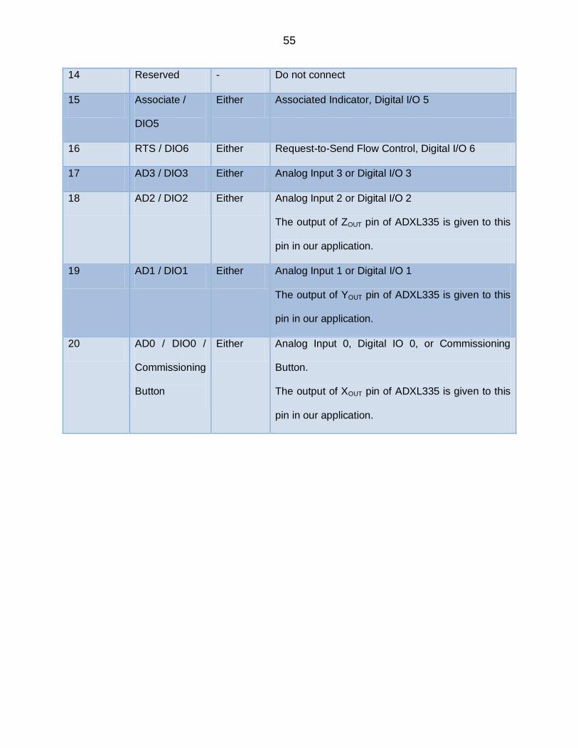
14 Reserved - Do not connect
15 Associate /
DIO5
Either Associated Indicator, Digital I/O 5
16 RTS / DIO6 Either Request-to-Send Flow Control, Digital I/O 6
17 AD3 / DIO3 Either Analog Input 3 or Digital I/O 3
18 AD2 / DIO2 Either Analog Input 2 or Digital I/O 2
The output of ZOUT pin of ADXL335 is given to this
pin in our application.
19 AD1 / DIO1 Either Analog Input 1 or Digital I/O 1
The output of YOUT pin of ADXL335 is given to this
pin in our application.
20 AD0 / DIO0 /
Commissioning
Button
Either Analog Input 0, Digital IO 0, or Commissioning
Button.
The output of XOUT pin of ADXL335 is given to this
pin in our application.

56
APPENDIX D: C++ CODE SNIPPET USING THE SERIAL CLASS
The code snippet describes instantiation of serial class, open the serial port,
define the commands for calibration and write them on the serial port. The variable
“accelerometer” in the code is defined as a struct which consists of two char members
“command1” and “carriageReturn”. The return value is read from the serial port and the
serial port is closed.

57
APPENDIX E: INITIALIZATION SEQUENCE CODE FOR THE NOVINT FALCON
The code represents the normal initialization sequence from initializing the
device, then the servo thread to setting up the callback function. Sequence is vital
particularly, “hdlCreateServoOp” must not be called before “hdlInitNamedDevice”, and if
“hdlStart” is not called until after “hdlCreateServoOp”, the device will not operate.

58
REFERENCES
[1] S. Hunt, "A framework for research in augmented teleoperation and
supervisory control for mobile robots," Master of Science Thesis, Electrical and
Computer Engineering, Wayne State University, Detroit, 2008.
[2] Q. Lin and C. Kuo, “Virtual tele-operation of underwater robots,” in
Proceedings of IEEE International Conference on Robotics and Automation,
Albuquerque, NM, USA, 1997.
[3] F. Smith, D. Backman, and S. Jacobsen, “Telerobotic manipulator for
hazardous environments,” in Journ. of Rob. Syst., vol. 9, NO. 2, pp. 251–260, 1992.
[4] J. P. K. Kim, H. Lee and M. Yang, “Robotic contamination cleaning
system,” in IEEE Conference on Intelligent Robots ans Systems, Lausanne,
Switzerland, October 2002.
[5] N. Diolaiti, and C. Melchiorri, “Tele-operation of a mobile robot through
haptic feedback,” in IEEE Int. workshop on Haptic Virtual Environments and Their
Applications, Ottawa, Ontario, canada, 17-18 November 2002.
[6] TARDEC - The US Army Tank Automotive Research and Engineering
Center. Available from: http://tardec.army.mil/default.aspx.

59
[7] L. Rosenberg, and S. Brave, “Using force feedback to enhance human
performance in graphical user interfaces,” in CHI ’96 Companion, Vancouver, BC
Canada, 13-18 April 1996.
[8] L. Rosenberg, “Virtual Fixtures: Perceptual Tools for Telerobotic
Manipulation,” in Proceedings IEEE Virtual Reality Annual International Symposium,
1993.
[9] J. Borenstein, H. Everett, L. Feng, and D. Wehe, “Mobile robot positioning
– sensors and techniques,” in Invited paper for the Journal of Robotic Systems, Special
Issue on Mobile Robots. Vol. 14 No. 4, pp. 231 – 249, 1997.
[10] H. Roth, K. Schilling, and O. Rösch, “Haptic Interfaces For Remote control
of Mobile Robots,” in 15th Triennial World Congress, Barcelona, Spain, 2002.
[11] J. Troy, C. Erignac, and P. Murray, “Haptics-Enabled UAV Teleoperation
Using Motion Capture Systems,” in Journal of Computing and Information Science in
Engineering, Vol. 9, March 2009.
[12] Klein, d. Serial Library for C++. Available from:
http://www.codeproject.com/KB/system/serial.aspx.
[13] T. G. Anderson, “A virtual universe utilizing haptic display,” in Proc. of the
First PHANToM User’s Group Workshop, Dedham, MA, USA, September 1996.
[14] W. Aviles and J. Ranta, “A brief presentation on the vrdts - virtual reality
dental training system,” in Proc. of the Fourth PHANToM User’s Group Workshop,
Deham, MA, USA, October 1999.

60
[15] I. Elhajj, N. Xi, and Y. H. Liu, “Real-time control of internet based
teleoperation with force reflection,” in Proc. of IEEE ICRA 2000, San Francisco, CA,
USA, April 2000.
[16] M. L. McLaughlin, G. Sukhatme, C. Shahabi, J. Hespanha, A. Ortega, and
G. Medioni, “The haptic museum,” in Proc. of the EVA 2000 Conference on Electronic
Imaging and the Visual Arts, Florence, Italy, 2000.
[17] M. A. Srinivasan and C. Basdogan, “Haptics in virtual environments:
Taxonomy, research status, and challenges,” in Computers & Graphics, 21(4):393–404,
1997.
[18] S. Lee, G. Sukhatme, G. J.Kim, and G. Park, “Haptic Teleoperation of a
mobile robot: A user study,” in IEEE Conference on Intelligent Robots ans Systems,
Lausanne, Switzerland, October 2002
[19] T. Fong, F. Conti, S. Grange, and C. Baur, “Novel interfaces for remote
driving: gesture, haptic and PDA,” SPIE Telemanipulator and Telepresence Technolgies
VII , 2000.
[20] S. Hunt, “Robotic Goal-based semi-autonomous algorithms improve
remote operator performance,” Doctor of Phillosophy, Dissertation, Computer
Engineering, Wayne State University, Detroit, 2010.
[21] T. Massie and J. Salisbury, “The PHANTOM haptic interface: a device for
probing virtual objects”, ASME Winter Annual Meeting: Symposium on Haptic Interfaces
for Virtual Environment and Teleoperator Systems, Chicago, IL, 1994.

61
[22] M. Kurze, “Rendering drawings for interactive haptic perception”,
Computer Human Interaction, Atlanta, GA, 1997.

62
ABSTRACT
DEVELOPMENT AND HUMAN PERFORMANCE EVALUATION OF A GROUND VEHICLE ROBOTIC FORCE-FEEDBACK TELE-OPERATION SYSTEM
by
ANKUR SARAF
May 2011
Advisor: Dr. Abhilash K. Pandya.
Major: Electrical Engineering.
Degree: Master of Science.
Modern tele-operation systems are trying to take into account haptic and audio
information in addition to visual data to provide as feedback to the tele-operator. This
research emphasizes on the development of hardware and software architecture to
enhance the tele-operation capabilities of omni-directional inspection robot (ODIS). The
system enhances the tele-operation capabilities by introducing force-feedback to the
tele-operators. The conventional joystick is replaced with Novint Falcon haptic joystick
which gets the feedback from the wireless accelerometer sensor module mounted on
the top of ODIS. The wireless accelerometer sensor module uses XBee modules for
sending the acceleration data to the server. The server in-turn is connected to the
joystick which is used to direct the ODIS. The advantage of the wireless accelerometer

63
system is it can be used not only with ODIS but with any other unmanned vehicle as
well. Though this research uses ODIS robot as the platform, the ideas and concepts put
forward are applicable to tele-operation of robots in general.

64
AUTOBIOGRAPHICAL STATEMENT
ANKUR SARAF
The passage of my life began in a city called Ujjain located in the central part of
India. I finished my entire schooling in Ujjain. I have been fascinated with electrical
circuits, semiconductor devices since school. Curiosity to know how these
semiconductor devices work and eagerness to explore them further, I decided to pursue
my engineering in electronics and communication from MIT, Ujjain (M.P.), Rajiv Gandhi
Technological University, Bhopal.
After completing Bachelors in 2006, I started working as an Embedded Software
Engineer in KPIT Cummins, Infosystems Limited, where I got an opportunity to work in
the embedded automotive domain. As a software engineer, my responsibilities involved
embedded software implementation, completely adhered to “software development life
cycle” involving requirement assessment, design & Coding, testing & validation of
automotive embedded modules.
After having experience in a real-life environment to develop embedded
applications in an industrial setting, I decided to pursue Master‟s degree in Electrical
Engineering at Wayne State University. I had the opportunity to work in the SSIM-
CARES lab as a graduate researcher. While pursuing this research, I got an opportunity
to work as a software engineering intern in a company which hired me as a full-time
engineer recently. I feel fabulously fortunate for all the opportunities I have had in my
life.


