Developer Tool Guide - Informatica · PowerMart, Metadata Manager, Informatica Data Quality,...
252
Informatica (Version 10.1) Developer Tool Guide
Transcript of Developer Tool Guide - Informatica · PowerMart, Metadata Manager, Informatica Data Quality,...

Informatica (Version 10.1)
Developer Tool Guide

Informatica Developer Tool Guide
Version 10.1June 2016
© Copyright Informatica LLC 1998, 2016
This software and documentation contain proprietary information of Informatica LLC and are provided under a license agreement containing restrictions on use and disclosure and are also protected by copyright law. Reverse engineering of the software is prohibited. No part of this document may be reproduced or transmitted in any form, by any means (electronic, photocopying, recording or otherwise) without prior consent of Informatica LLC. This Software may be protected by U.S. and/or international Patents and other Patents Pending.
Use, duplication, or disclosure of the Software by the U.S. Government is subject to the restrictions set forth in the applicable software license agreement and as provided in DFARS 227.7202-1(a) and 227.7702-3(a) (1995), DFARS 252.227-7013©(1)(ii) (OCT 1988), FAR 12.212(a) (1995), FAR 52.227-19, or FAR 52.227-14 (ALT III), as applicable.
The information in this product or documentation is subject to change without notice. If you find any problems in this product or documentation, please report them to us in writing.
Informatica, Informatica Platform, Informatica Data Services, PowerCenter, PowerCenterRT, PowerCenter Connect, PowerCenter Data Analyzer, PowerExchange, PowerMart, Metadata Manager, Informatica Data Quality, Informatica Data Explorer, Informatica B2B Data Transformation, Informatica B2B Data Exchange Informatica On Demand, Informatica Identity Resolution, Informatica Application Information Lifecycle Management, Informatica Complex Event Processing, Ultra Messaging, Informatica Master Data Management, and Live Data Map are trademarks or registered trademarks of Informatica LLC in the United States and in jurisdictions throughout the world. All other company and product names may be trade names or trademarks of their respective owners.
Portions of this software and/or documentation are subject to copyright held by third parties, including without limitation: Copyright DataDirect Technologies. All rights reserved. Copyright © Sun Microsystems. All rights reserved. Copyright © RSA Security Inc. All Rights Reserved. Copyright © Ordinal Technology Corp. All rights reserved. Copyright © Aandacht c.v. All rights reserved. Copyright Genivia, Inc. All rights reserved. Copyright Isomorphic Software. All rights reserved. Copyright © Meta Integration Technology, Inc. All rights reserved. Copyright © Intalio. All rights reserved. Copyright © Oracle. All rights reserved. Copyright © Adobe Systems Incorporated. All rights reserved. Copyright © DataArt, Inc. All rights reserved. Copyright © ComponentSource. All rights reserved. Copyright © Microsoft Corporation. All rights reserved. Copyright © Rogue Wave Software, Inc. All rights reserved. Copyright © Teradata Corporation. All rights reserved. Copyright © Yahoo! Inc. All rights reserved. Copyright © Glyph & Cog, LLC. All rights reserved. Copyright © Thinkmap, Inc. All rights reserved. Copyright © Clearpace Software Limited. All rights reserved. Copyright © Information Builders, Inc. All rights reserved. Copyright © OSS Nokalva, Inc. All rights reserved. Copyright Edifecs, Inc. All rights reserved. Copyright Cleo Communications, Inc. All rights reserved. Copyright © International Organization for Standardization 1986. All rights reserved. Copyright © ej-technologies GmbH. All rights reserved. Copyright © Jaspersoft Corporation. All rights reserved. Copyright © International Business Machines Corporation. All rights reserved. Copyright © yWorks GmbH. All rights reserved. Copyright © Lucent Technologies. All rights reserved. Copyright (c) University of Toronto. All rights reserved. Copyright © Daniel Veillard. All rights reserved. Copyright © Unicode, Inc. Copyright IBM Corp. All rights reserved. Copyright © MicroQuill Software Publishing, Inc. All rights reserved. Copyright © PassMark Software Pty Ltd. All rights reserved. Copyright © LogiXML, Inc. All rights reserved. Copyright © 2003-2010 Lorenzi Davide, All rights reserved. Copyright © Red Hat, Inc. All rights reserved. Copyright © The Board of Trustees of the Leland Stanford Junior University. All rights reserved. Copyright © EMC Corporation. All rights reserved. Copyright © Flexera Software. All rights reserved. Copyright © Jinfonet Software. All rights reserved. Copyright © Apple Inc. All rights reserved. Copyright © Telerik Inc. All rights reserved. Copyright © BEA Systems. All rights reserved. Copyright © PDFlib GmbH. All rights reserved. Copyright © Orientation in Objects GmbH. All rights reserved. Copyright © Tanuki Software, Ltd. All rights reserved. Copyright © Ricebridge. All rights reserved. Copyright © Sencha, Inc. All rights reserved. Copyright © Scalable Systems, Inc. All rights reserved. Copyright © jQWidgets. All rights reserved. Copyright © Tableau Software, Inc. All rights reserved. Copyright© MaxMind, Inc. All Rights Reserved. Copyright © TMate Software s.r.o. All rights reserved. Copyright © MapR Technologies Inc. All rights reserved. Copyright © Amazon Corporate LLC. All rights reserved. Copyright © Highsoft. All rights reserved. Copyright © Python Software Foundation. All rights reserved. Copyright © BeOpen.com. All rights reserved. Copyright © CNRI. All rights reserved.
This product includes software developed by the Apache Software Foundation (http://www.apache.org/), and/or other software which is licensed under various versions of the Apache License (the "License"). You may obtain a copy of these Licenses at http://www.apache.org/licenses/. Unless required by applicable law or agreed to in writing, software distributed under these Licenses is distributed on an "AS IS" BASIS, WITHOUT WARRANTIES OR CONDITIONS OF ANY KIND, either express or implied. See the Licenses for the specific language governing permissions and limitations under the Licenses.
This product includes software which was developed by Mozilla (http://www.mozilla.org/), software copyright The JBoss Group, LLC, all rights reserved; software copyright © 1999-2006 by Bruno Lowagie and Paulo Soares and other software which is licensed under various versions of the GNU Lesser General Public License Agreement, which may be found at http:// www.gnu.org/licenses/lgpl.html. The materials are provided free of charge by Informatica, "as-is", without warranty of any kind, either express or implied, including but not limited to the implied warranties of merchantability and fitness for a particular purpose.
The product includes ACE(TM) and TAO(TM) software copyrighted by Douglas C. Schmidt and his research group at Washington University, University of California, Irvine, and Vanderbilt University, Copyright (©) 1993-2006, all rights reserved.
This product includes software developed by the OpenSSL Project for use in the OpenSSL Toolkit (copyright The OpenSSL Project. All Rights Reserved) and redistribution of this software is subject to terms available at http://www.openssl.org and http://www.openssl.org/source/license.html.
This product includes Curl software which is Copyright 1996-2013, Daniel Stenberg, <[email protected]>. All Rights Reserved. Permissions and limitations regarding this software are subject to terms available at http://curl.haxx.se/docs/copyright.html. Permission to use, copy, modify, and distribute this software for any purpose with or without fee is hereby granted, provided that the above copyright notice and this permission notice appear in all copies.
The product includes software copyright 2001-2005 (©) MetaStuff, Ltd. All Rights Reserved. Permissions and limitations regarding this software are subject to terms available at http://www.dom4j.org/ license.html.
The product includes software copyright © 2004-2007, The Dojo Foundation. All Rights Reserved. Permissions and limitations regarding this software are subject to terms available at http://dojotoolkit.org/license.
This product includes ICU software which is copyright International Business Machines Corporation and others. All rights reserved. Permissions and limitations regarding this software are subject to terms available at http://source.icu-project.org/repos/icu/icu/trunk/license.html.
This product includes software copyright © 1996-2006 Per Bothner. All rights reserved. Your right to use such materials is set forth in the license which may be found at http:// www.gnu.org/software/ kawa/Software-License.html.
This product includes OSSP UUID software which is Copyright © 2002 Ralf S. Engelschall, Copyright © 2002 The OSSP Project Copyright © 2002 Cable & Wireless Deutschland. Permissions and limitations regarding this software are subject to terms available at http://www.opensource.org/licenses/mit-license.php.
This product includes software developed by Boost (http://www.boost.org/) or under the Boost software license. Permissions and limitations regarding this software are subject to terms available at http:/ /www.boost.org/LICENSE_1_0.txt.
This product includes software copyright © 1997-2007 University of Cambridge. Permissions and limitations regarding this software are subject to terms available at http:// www.pcre.org/license.txt.
This product includes software copyright © 2007 The Eclipse Foundation. All Rights Reserved. Permissions and limitations regarding this software are subject to terms available at http:// www.eclipse.org/org/documents/epl-v10.php and at http://www.eclipse.org/org/documents/edl-v10.php.

This product includes software licensed under the terms at http://www.tcl.tk/software/tcltk/license.html, http://www.bosrup.com/web/overlib/?License, http://www.stlport.org/doc/ license.html, http://asm.ow2.org/license.html, http://www.cryptix.org/LICENSE.TXT, http://hsqldb.org/web/hsqlLicense.html, http://httpunit.sourceforge.net/doc/ license.html, http://jung.sourceforge.net/license.txt , http://www.gzip.org/zlib/zlib_license.html, http://www.openldap.org/software/release/license.html, http://www.libssh2.org, http://slf4j.org/license.html, http://www.sente.ch/software/OpenSourceLicense.html, http://fusesource.com/downloads/license-agreements/fuse-message-broker-v-5-3- license-agreement; http://antlr.org/license.html; http://aopalliance.sourceforge.net/; http://www.bouncycastle.org/licence.html; http://www.jgraph.com/jgraphdownload.html; http://www.jcraft.com/jsch/LICENSE.txt; http://jotm.objectweb.org/bsd_license.html; . http://www.w3.org/Consortium/Legal/2002/copyright-software-20021231; http://www.slf4j.org/license.html; http://nanoxml.sourceforge.net/orig/copyright.html; http://www.json.org/license.html; http://forge.ow2.org/projects/javaservice/, http://www.postgresql.org/about/licence.html, http://www.sqlite.org/copyright.html, http://www.tcl.tk/software/tcltk/license.html, http://www.jaxen.org/faq.html, http://www.jdom.org/docs/faq.html, http://www.slf4j.org/license.html; http://www.iodbc.org/dataspace/iodbc/wiki/iODBC/License; http://www.keplerproject.org/md5/license.html; http://www.toedter.com/en/jcalendar/license.html; http://www.edankert.com/bounce/index.html; http://www.net-snmp.org/about/license.html; http://www.openmdx.org/#FAQ; http://www.php.net/license/3_01.txt; http://srp.stanford.edu/license.txt; http://www.schneier.com/blowfish.html; http://www.jmock.org/license.html; http://xsom.java.net; http://benalman.com/about/license/; https://github.com/CreateJS/EaselJS/blob/master/src/easeljs/display/Bitmap.js; http://www.h2database.com/html/license.html#summary; http://jsoncpp.sourceforge.net/LICENSE; http://jdbc.postgresql.org/license.html; http://protobuf.googlecode.com/svn/trunk/src/google/protobuf/descriptor.proto; https://github.com/rantav/hector/blob/master/LICENSE; http://web.mit.edu/Kerberos/krb5-current/doc/mitK5license.html; http://jibx.sourceforge.net/jibx-license.html; https://github.com/lyokato/libgeohash/blob/master/LICENSE; https://github.com/hjiang/jsonxx/blob/master/LICENSE; https://code.google.com/p/lz4/; https://github.com/jedisct1/libsodium/blob/master/LICENSE; http://one-jar.sourceforge.net/index.php?page=documents&file=license; https://github.com/EsotericSoftware/kryo/blob/master/license.txt; http://www.scala-lang.org/license.html; https://github.com/tinkerpop/blueprints/blob/master/LICENSE.txt; http://gee.cs.oswego.edu/dl/classes/EDU/oswego/cs/dl/util/concurrent/intro.html; https://aws.amazon.com/asl/; https://github.com/twbs/bootstrap/blob/master/LICENSE; https://sourceforge.net/p/xmlunit/code/HEAD/tree/trunk/LICENSE.txt; https://github.com/documentcloud/underscore-contrib/blob/master/LICENSE, and https://github.com/apache/hbase/blob/master/LICENSE.txt.
This product includes software licensed under the Academic Free License (http://www.opensource.org/licenses/afl-3.0.php), the Common Development and Distribution License (http://www.opensource.org/licenses/cddl1.php) the Common Public License (http://www.opensource.org/licenses/cpl1.0.php), the Sun Binary Code License Agreement Supplemental License Terms, the BSD License (http:// www.opensource.org/licenses/bsd-license.php), the new BSD License (http://opensource.org/licenses/BSD-3-Clause), the MIT License (http://www.opensource.org/licenses/mit-license.php), the Artistic License (http://www.opensource.org/licenses/artistic-license-1.0) and the Initial Developer’s Public License Version 1.0 (http://www.firebirdsql.org/en/initial-developer-s-public-license-version-1-0/).
This product includes software copyright © 2003-2006 Joe WaInes, 2006-2007 XStream Committers. All rights reserved. Permissions and limitations regarding this software are subject to terms available at http://xstream.codehaus.org/license.html. This product includes software developed by the Indiana University Extreme! Lab. For further information please visit http://www.extreme.indiana.edu/.
This product includes software Copyright (c) 2013 Frank Balluffi and Markus Moeller. All rights reserved. Permissions and limitations regarding this software are subject to terms of the MIT license.
See patents at https://www.informatica.com/legal/patents.html.
DISCLAIMER: Informatica LLC provides this documentation "as is" without warranty of any kind, either express or implied, including, but not limited to, the implied warranties of noninfringement, merchantability, or use for a particular purpose. Informatica LLC does not warrant that this software or documentation is error free. The information provided in this software or documentation may include technical inaccuracies or typographical errors. The information in this software and documentation is subject to change at any time without notice.
NOTICES
This Informatica product (the "Software") includes certain drivers (the "DataDirect Drivers") from DataDirect Technologies, an operating company of Progress Software Corporation ("DataDirect") which are subject to the following terms and conditions:
1.THE DATADIRECT DRIVERS ARE PROVIDED "AS IS" WITHOUT WARRANTY OF ANY KIND, EITHER EXPRESSED OR IMPLIED, INCLUDING BUT NOT LIMITED TO, THE IMPLIED WARRANTIES OF MERCHANTABILITY, FITNESS FOR A PARTICULAR PURPOSE AND NON-INFRINGEMENT.
2. IN NO EVENT WILL DATADIRECT OR ITS THIRD PARTY SUPPLIERS BE LIABLE TO THE END-USER CUSTOMER FOR ANY DIRECT, INDIRECT, INCIDENTAL, SPECIAL, CONSEQUENTIAL OR OTHER DAMAGES ARISING OUT OF THE USE OF THE ODBC DRIVERS, WHETHER OR NOT INFORMED OF THE POSSIBILITIES OF DAMAGES IN ADVANCE. THESE LIMITATIONS APPLY TO ALL CAUSES OF ACTION, INCLUDING, WITHOUT LIMITATION, BREACH OF CONTRACT, BREACH OF WARRANTY, NEGLIGENCE, STRICT LIABILITY, MISREPRESENTATION AND OTHER TORTS.
Part Number: IN-DUG-10000-0001

Table of Contents
Preface . . . . . . . . . . . . . . . . . . . . . . . . . . . . . . . . . . . . . . . . . . . . . . . . . . . . . . . . . . . . . . . . . . . . . 12Informatica Resources. . . . . . . . . . . . . . . . . . . . . . . . . . . . . . . . . . . . . . . . . . . . . . . . . . 12
Informatica Network. . . . . . . . . . . . . . . . . . . . . . . . . . . . . . . . . . . . . . . . . . . . . . . . . 12
Informatica Knowledge Base. . . . . . . . . . . . . . . . . . . . . . . . . . . . . . . . . . . . . . . . . . . 12
Informatica Documentation. . . . . . . . . . . . . . . . . . . . . . . . . . . . . . . . . . . . . . . . . . . . 12
Informatica Product Availability Matrixes. . . . . . . . . . . . . . . . . . . . . . . . . . . . . . . . . . . . 13
Informatica Velocity. . . . . . . . . . . . . . . . . . . . . . . . . . . . . . . . . . . . . . . . . . . . . . . . . 13
Informatica Marketplace. . . . . . . . . . . . . . . . . . . . . . . . . . . . . . . . . . . . . . . . . . . . . . 13
Informatica Global Customer Support. . . . . . . . . . . . . . . . . . . . . . . . . . . . . . . . . . . . . . 13
Chapter 1: Informatica Developer. . . . . . . . . . . . . . . . . . . . . . . . . . . . . . . . . . . . . . . . . . . . . 14Informatica Developer Overview. . . . . . . . . . . . . . . . . . . . . . . . . . . . . . . . . . . . . . . . . . . . 14
Informatica Data Quality and Profiling. . . . . . . . . . . . . . . . . . . . . . . . . . . . . . . . . . . . . 14
Informatica Data Services. . . . . . . . . . . . . . . . . . . . . . . . . . . . . . . . . . . . . . . . . . . . . 15
Start Informatica Developer. . . . . . . . . . . . . . . . . . . . . . . . . . . . . . . . . . . . . . . . . . . . . . . 16
Starting the Developer Tool on a Local Machine. . . . . . . . . . . . . . . . . . . . . . . . . . . . . . . 16
Starting the Developer Tool on a Remote Machine. . . . . . . . . . . . . . . . . . . . . . . . . . . . . 16
Informatica Developer Interface. . . . . . . . . . . . . . . . . . . . . . . . . . . . . . . . . . . . . . . . . . . . 17
Informatica Developer Views. . . . . . . . . . . . . . . . . . . . . . . . . . . . . . . . . . . . . . . . . . . 17
Informatica Developer Welcome Page. . . . . . . . . . . . . . . . . . . . . . . . . . . . . . . . . . . . . 19
Cheat Sheets. . . . . . . . . . . . . . . . . . . . . . . . . . . . . . . . . . . . . . . . . . . . . . . . . . . . . 19
Informatica Developer Online Help. . . . . . . . . . . . . . . . . . . . . . . . . . . . . . . . . . . . . . . 19
Informatica Preferences. . . . . . . . . . . . . . . . . . . . . . . . . . . . . . . . . . . . . . . . . . . . . . 19
Informatica Marketplace. . . . . . . . . . . . . . . . . . . . . . . . . . . . . . . . . . . . . . . . . . . . . . 20
Setting Up Informatica Developer. . . . . . . . . . . . . . . . . . . . . . . . . . . . . . . . . . . . . . . . . . . 20
Step 1. Add a Domain. . . . . . . . . . . . . . . . . . . . . . . . . . . . . . . . . . . . . . . . . . . . . . . . 20
Step 2. Add a Model Repository. . . . . . . . . . . . . . . . . . . . . . . . . . . . . . . . . . . . . . . . . 21
Step 3. Select a Default Data Integration Service. . . . . . . . . . . . . . . . . . . . . . . . . . . . . . 21
Domains. . . . . . . . . . . . . . . . . . . . . . . . . . . . . . . . . . . . . . . . . . . . . . . . . . . . . . . . . . . 21
Projects. . . . . . . . . . . . . . . . . . . . . . . . . . . . . . . . . . . . . . . . . . . . . . . . . . . . . . . . . . . . 22
Creating a Project. . . . . . . . . . . . . . . . . . . . . . . . . . . . . . . . . . . . . . . . . . . . . . . . . . 22
Filter Projects. . . . . . . . . . . . . . . . . . . . . . . . . . . . . . . . . . . . . . . . . . . . . . . . . . . . . 22
Project Permissions. . . . . . . . . . . . . . . . . . . . . . . . . . . . . . . . . . . . . . . . . . . . . . . . . . . . 23
Permissions for External Objects. . . . . . . . . . . . . . . . . . . . . . . . . . . . . . . . . . . . . . . . . 23
Permissions for Dependent Object Instances. . . . . . . . . . . . . . . . . . . . . . . . . . . . . . . . . 24
Parent Object Access. . . . . . . . . . . . . . . . . . . . . . . . . . . . . . . . . . . . . . . . . . . . . . . . 25
Assigning Permissions. . . . . . . . . . . . . . . . . . . . . . . . . . . . . . . . . . . . . . . . . . . . . . . 25
Folders. . . . . . . . . . . . . . . . . . . . . . . . . . . . . . . . . . . . . . . . . . . . . . . . . . . . . . . . . . . . 26
Creating a Folder. . . . . . . . . . . . . . . . . . . . . . . . . . . . . . . . . . . . . . . . . . . . . . . . . . . 26
Copy Object Operations. . . . . . . . . . . . . . . . . . . . . . . . . . . . . . . . . . . . . . . . . . . . . . . . . 26
4 Table of Contents

Copying an Object. . . . . . . . . . . . . . . . . . . . . . . . . . . . . . . . . . . . . . . . . . . . . . . . . . 27
Saving a Copy of an Object. . . . . . . . . . . . . . . . . . . . . . . . . . . . . . . . . . . . . . . . . . . . 27
Tags. . . . . . . . . . . . . . . . . . . . . . . . . . . . . . . . . . . . . . . . . . . . . . . . . . . . . . . . . . . . . . 27
Creating a Tag. . . . . . . . . . . . . . . . . . . . . . . . . . . . . . . . . . . . . . . . . . . . . . . . . . . . 28
Assigning a Tag. . . . . . . . . . . . . . . . . . . . . . . . . . . . . . . . . . . . . . . . . . . . . . . . . . . 28
Viewing Tags. . . . . . . . . . . . . . . . . . . . . . . . . . . . . . . . . . . . . . . . . . . . . . . . . . . . . 28
Chapter 2: The Model Repository. . . . . . . . . . . . . . . . . . . . . . . . . . . . . . . . . . . . . . . . . . . . . 29Model Repository Overview. . . . . . . . . . . . . . . . . . . . . . . . . . . . . . . . . . . . . . . . . . . . . . . 29
Objects in Informatica Developer. . . . . . . . . . . . . . . . . . . . . . . . . . . . . . . . . . . . . . . . . . . . 30
Object Properties. . . . . . . . . . . . . . . . . . . . . . . . . . . . . . . . . . . . . . . . . . . . . . . . . . . 32
Repository Object Locks. . . . . . . . . . . . . . . . . . . . . . . . . . . . . . . . . . . . . . . . . . . . . . . . . 32
Lock Management. . . . . . . . . . . . . . . . . . . . . . . . . . . . . . . . . . . . . . . . . . . . . . . . . . 32
Rules and Guidelines for Lock Management. . . . . . . . . . . . . . . . . . . . . . . . . . . . . . . . . 33
Team-based Development with Versioned Objects. . . . . . . . . . . . . . . . . . . . . . . . . . . . . . . . 34
Versioned Object Management. . . . . . . . . . . . . . . . . . . . . . . . . . . . . . . . . . . . . . . . . . 34
Historical Versions of Objects. . . . . . . . . . . . . . . . . . . . . . . . . . . . . . . . . . . . . . . . . . . 36
Checked Out Objects View. . . . . . . . . . . . . . . . . . . . . . . . . . . . . . . . . . . . . . . . . . . . 37
Version History View. . . . . . . . . . . . . . . . . . . . . . . . . . . . . . . . . . . . . . . . . . . . . . . . 37
Troubleshooting Team-based Development. . . . . . . . . . . . . . . . . . . . . . . . . . . . . . . . . . 38
Connecting to a Model Repository. . . . . . . . . . . . . . . . . . . . . . . . . . . . . . . . . . . . . . . . . . . 38
Model Repository Service Refresh. . . . . . . . . . . . . . . . . . . . . . . . . . . . . . . . . . . . . . . . . . . 38
Chapter 3: Searches in Informatica Developer. . . . . . . . . . . . . . . . . . . . . . . . . . . . . . . . . 39Searches in Informatica Developer Overview. . . . . . . . . . . . . . . . . . . . . . . . . . . . . . . . . . . . 39
Model Repository Search. . . . . . . . . . . . . . . . . . . . . . . . . . . . . . . . . . . . . . . . . . . . . . . . 39
Searching for Objects and Properties. . . . . . . . . . . . . . . . . . . . . . . . . . . . . . . . . . . . . . 40
Business Glossary Search. . . . . . . . . . . . . . . . . . . . . . . . . . . . . . . . . . . . . . . . . . . . . . . . 40
Business Glossary Desktop Lookup. . . . . . . . . . . . . . . . . . . . . . . . . . . . . . . . . . . . . . . 41
Looking Up a Business Term. . . . . . . . . . . . . . . . . . . . . . . . . . . . . . . . . . . . . . . . . . . 41
Customizing Hotkeys to Look Up a Business Term. . . . . . . . . . . . . . . . . . . . . . . . . . . . . 41
Editor Search. . . . . . . . . . . . . . . . . . . . . . . . . . . . . . . . . . . . . . . . . . . . . . . . . . . . . . . . 42
Chapter 4: Connections. . . . . . . . . . . . . . . . . . . . . . . . . . . . . . . . . . . . . . . . . . . . . . . . . . . . . . 43Connections Overview. . . . . . . . . . . . . . . . . . . . . . . . . . . . . . . . . . . . . . . . . . . . . . . . . . 43
Connection Types . . . . . . . . . . . . . . . . . . . . . . . . . . . . . . . . . . . . . . . . . . . . . . . . . . 44
Connection Explorer View. . . . . . . . . . . . . . . . . . . . . . . . . . . . . . . . . . . . . . . . . . . . . . . . 45
Connection Management. . . . . . . . . . . . . . . . . . . . . . . . . . . . . . . . . . . . . . . . . . . . . . . . . 46
Creating a Connection . . . . . . . . . . . . . . . . . . . . . . . . . . . . . . . . . . . . . . . . . . . . . . . 46
Editing a Connection. . . . . . . . . . . . . . . . . . . . . . . . . . . . . . . . . . . . . . . . . . . . . . . . 47
Copying a Connection. . . . . . . . . . . . . . . . . . . . . . . . . . . . . . . . . . . . . . . . . . . . . . . 47
Deleting a Connection. . . . . . . . . . . . . . . . . . . . . . . . . . . . . . . . . . . . . . . . . . . . . . . 48
Refreshing the Connections List. . . . . . . . . . . . . . . . . . . . . . . . . . . . . . . . . . . . . . . . . 48
Table of Contents 5

Connection Switching. . . . . . . . . . . . . . . . . . . . . . . . . . . . . . . . . . . . . . . . . . . . . . . . . . . 48
Before You Switch a Connection. . . . . . . . . . . . . . . . . . . . . . . . . . . . . . . . . . . . . . . . . 49
Switching a Connection. . . . . . . . . . . . . . . . . . . . . . . . . . . . . . . . . . . . . . . . . . . . . . . 49
After You Switch a Connection. . . . . . . . . . . . . . . . . . . . . . . . . . . . . . . . . . . . . . . . . . 50
Third-Party JDBC Drivers. . . . . . . . . . . . . . . . . . . . . . . . . . . . . . . . . . . . . . . . . . . . . . . . 52
Chapter 5: Physical Data Objects. . . . . . . . . . . . . . . . . . . . . . . . . . . . . . . . . . . . . . . . . . . . . 53Physical Data Objects Overview. . . . . . . . . . . . . . . . . . . . . . . . . . . . . . . . . . . . . . . . . . . . 53
Physical Data Object Types. . . . . . . . . . . . . . . . . . . . . . . . . . . . . . . . . . . . . . . . . . . . . . . 54
Relational Data Objects. . . . . . . . . . . . . . . . . . . . . . . . . . . . . . . . . . . . . . . . . . . . . . . . . 54
Importing a Relational Data Object. . . . . . . . . . . . . . . . . . . . . . . . . . . . . . . . . . . . . . . 56
Key Relationships. . . . . . . . . . . . . . . . . . . . . . . . . . . . . . . . . . . . . . . . . . . . . . . . . . 56
Customized Data Objects. . . . . . . . . . . . . . . . . . . . . . . . . . . . . . . . . . . . . . . . . . . . . . . . 57
Key Relationships. . . . . . . . . . . . . . . . . . . . . . . . . . . . . . . . . . . . . . . . . . . . . . . . . . 59
Customized Data Object Write Properties. . . . . . . . . . . . . . . . . . . . . . . . . . . . . . . . . . . 60
Creating a Customized Data Object. . . . . . . . . . . . . . . . . . . . . . . . . . . . . . . . . . . . . . . 61
Adding Relational Resources to a Customized Data Object. . . . . . . . . . . . . . . . . . . . . . . . 61
Adding Relational Data Objects to a Customized Data Object. . . . . . . . . . . . . . . . . . . . . . 61
Creating Keys in a Customized Data Object. . . . . . . . . . . . . . . . . . . . . . . . . . . . . . . . . . 62
Creating Relationships within a Customized Data Object. . . . . . . . . . . . . . . . . . . . . . . . . 62
Create or Replace Target Tables. . . . . . . . . . . . . . . . . . . . . . . . . . . . . . . . . . . . . . . . . . . 63
Rules and Guidelines to Create or Replace Target Tables. . . . . . . . . . . . . . . . . . . . . . . . 63
Generating and Executing DDL at Design-Time. . . . . . . . . . . . . . . . . . . . . . . . . . . . . . . 64
Generating and Executing DDL at Runtime. . . . . . . . . . . . . . . . . . . . . . . . . . . . . . . . . . 66
DDL Generation Errors. . . . . . . . . . . . . . . . . . . . . . . . . . . . . . . . . . . . . . . . . . . . . . . 66
Custom Queries. . . . . . . . . . . . . . . . . . . . . . . . . . . . . . . . . . . . . . . . . . . . . . . . . . . . . . 66
Custom Query Optimization. . . . . . . . . . . . . . . . . . . . . . . . . . . . . . . . . . . . . . . . . . . . 67
Default Query. . . . . . . . . . . . . . . . . . . . . . . . . . . . . . . . . . . . . . . . . . . . . . . . . . . . . 67
Hints. . . . . . . . . . . . . . . . . . . . . . . . . . . . . . . . . . . . . . . . . . . . . . . . . . . . . . . . . . . 68
Select Distinct. . . . . . . . . . . . . . . . . . . . . . . . . . . . . . . . . . . . . . . . . . . . . . . . . . . . . 69
Filters. . . . . . . . . . . . . . . . . . . . . . . . . . . . . . . . . . . . . . . . . . . . . . . . . . . . . . . . . . 70
Sorted Ports. . . . . . . . . . . . . . . . . . . . . . . . . . . . . . . . . . . . . . . . . . . . . . . . . . . . . . 70
User-Defined Joins. . . . . . . . . . . . . . . . . . . . . . . . . . . . . . . . . . . . . . . . . . . . . . . . . 72
Outer Join Support. . . . . . . . . . . . . . . . . . . . . . . . . . . . . . . . . . . . . . . . . . . . . . . . . . 73
Informatica Join Syntax. . . . . . . . . . . . . . . . . . . . . . . . . . . . . . . . . . . . . . . . . . . . . . . 73
Pre- and Post-Mapping SQL Commands. . . . . . . . . . . . . . . . . . . . . . . . . . . . . . . . . . . . 77
Creating a Custom Query. . . . . . . . . . . . . . . . . . . . . . . . . . . . . . . . . . . . . . . . . . . . . 78
Nonrelational Data Objects. . . . . . . . . . . . . . . . . . . . . . . . . . . . . . . . . . . . . . . . . . . . . . . 78
Importing a Nonrelational Data Object. . . . . . . . . . . . . . . . . . . . . . . . . . . . . . . . . . . . . 79
Creating a Read, Write, or Lookup Transformation from Nonrelational Data Operations. . . . . . 79
WSDL Data Object. . . . . . . . . . . . . . . . . . . . . . . . . . . . . . . . . . . . . . . . . . . . . . . . . . . . . 80
WSDL Data Object Overview View. . . . . . . . . . . . . . . . . . . . . . . . . . . . . . . . . . . . . . . 80
WSDL Data Object Advanced View. . . . . . . . . . . . . . . . . . . . . . . . . . . . . . . . . . . . . . . 81
6 Table of Contents
Importing a WSDL Data Object. . . . . . . . . . . . . . . . . . . . . . . . . . . . . . . . . . . . . . . . . . 81
WSDL Synchronization. . . . . . . . . . . . . . . . . . . . . . . . . . . . . . . . . . . . . . . . . . . . . . . 81
Certificate Management. . . . . . . . . . . . . . . . . . . . . . . . . . . . . . . . . . . . . . . . . . . . . . 82
Synchronization. . . . . . . . . . . . . . . . . . . . . . . . . . . . . . . . . . . . . . . . . . . . . . . . . . . . . . 83
Synchronizing a Flat File Data Object. . . . . . . . . . . . . . . . . . . . . . . . . . . . . . . . . . . . . . 83
Synchronizing a Relational Data Object. . . . . . . . . . . . . . . . . . . . . . . . . . . . . . . . . . . . 84
Troubleshooting Physical Data Objects. . . . . . . . . . . . . . . . . . . . . . . . . . . . . . . . . . . . . . . . 84
Chapter 6: Flat File Data Objects. . . . . . . . . . . . . . . . . . . . . . . . . . . . . . . . . . . . . . . . . . . . . . 85Flat File Data Objects Overview. . . . . . . . . . . . . . . . . . . . . . . . . . . . . . . . . . . . . . . . . . . . 85
Generate the Source File Name. . . . . . . . . . . . . . . . . . . . . . . . . . . . . . . . . . . . . . . . . . . . 86
Flat File Data Object Overview Properties. . . . . . . . . . . . . . . . . . . . . . . . . . . . . . . . . . . . . . 86
Flat File Data Object Advanced Properties. . . . . . . . . . . . . . . . . . . . . . . . . . . . . . . . . . . . . 87
Format Properties. . . . . . . . . . . . . . . . . . . . . . . . . . . . . . . . . . . . . . . . . . . . . . . . . . 88
Column Format: Delimited Properties. . . . . . . . . . . . . . . . . . . . . . . . . . . . . . . . . . . . . . 89
Column Format: Fixed-width Properties. . . . . . . . . . . . . . . . . . . . . . . . . . . . . . . . . . . . 89
Run-time: Read Properties. . . . . . . . . . . . . . . . . . . . . . . . . . . . . . . . . . . . . . . . . . . . . 91
Run-time: Write Properties. . . . . . . . . . . . . . . . . . . . . . . . . . . . . . . . . . . . . . . . . . . . . 93
Control File. . . . . . . . . . . . . . . . . . . . . . . . . . . . . . . . . . . . . . . . . . . . . . . . . . . . . . . . . 94
Update Columns at Run Time. . . . . . . . . . . . . . . . . . . . . . . . . . . . . . . . . . . . . . . . . . . . . . 95
Generate Run-time Column Names Automatically. . . . . . . . . . . . . . . . . . . . . . . . . . . . . . 95
Generate Run-time Column Names From Data File Header. . . . . . . . . . . . . . . . . . . . . . . . 96
Generate Column Metadata from Control Files. . . . . . . . . . . . . . . . . . . . . . . . . . . . . . . . . . . 96
Control File Formats. . . . . . . . . . . . . . . . . . . . . . . . . . . . . . . . . . . . . . . . . . . . . . . . . 97
Parameterization of Run-time Properties. . . . . . . . . . . . . . . . . . . . . . . . . . . . . . . . . . . . 97
Run-time Processing of Control Files. . . . . . . . . . . . . . . . . . . . . . . . . . . . . . . . . . . . . . 98
Rules and Guidelines for Control Files. . . . . . . . . . . . . . . . . . . . . . . . . . . . . . . . . . . . . 98
Create a Flat File Data Object. . . . . . . . . . . . . . . . . . . . . . . . . . . . . . . . . . . . . . . . . . . . . 99
Creating an Empty Flat File Data Object. . . . . . . . . . . . . . . . . . . . . . . . . . . . . . . . . . . . 99
Creating a Flat File Data Object from an Existing Flat File. . . . . . . . . . . . . . . . . . . . . . . . 100
Creating a Flat File Data Object from a Control File. . . . . . . . . . . . . . . . . . . . . . . . . . . . 101
Chapter 7: Logical View of Data. . . . . . . . . . . . . . . . . . . . . . . . . . . . . . . . . . . . . . . . . . . . . 103Logical View of Data Overview. . . . . . . . . . . . . . . . . . . . . . . . . . . . . . . . . . . . . . . . . . . . 103
Logical Data Object Model Example. . . . . . . . . . . . . . . . . . . . . . . . . . . . . . . . . . . . . . 104
Developing a Logical View of Data. . . . . . . . . . . . . . . . . . . . . . . . . . . . . . . . . . . . . . . . . . 104
Logical Data Object Models. . . . . . . . . . . . . . . . . . . . . . . . . . . . . . . . . . . . . . . . . . . . . . 105
Creating a Logical Data Object Model. . . . . . . . . . . . . . . . . . . . . . . . . . . . . . . . . . . . . 105
Importing a Logical Data Object Model from a Modeling Tool. . . . . . . . . . . . . . . . . . . . . . 106
Logical Data Object Model Properties. . . . . . . . . . . . . . . . . . . . . . . . . . . . . . . . . . . . . . . . 106
CA ERwin Data Modeler Import Properties. . . . . . . . . . . . . . . . . . . . . . . . . . . . . . . . . 107
IBM Cognos Business Intelligence Reporting - Framework Manager Import Properties. . . . . 108
SAP BusinessObjects Designer Import Properties. . . . . . . . . . . . . . . . . . . . . . . . . . . . . 109
Table of Contents 7

SAP PowerDesigner CDM Import Properties. . . . . . . . . . . . . . . . . . . . . . . . . . . . . . . . 110
SAP PowerDesigner OOM 9.x to 15.x Import Properties. . . . . . . . . . . . . . . . . . . . . . . . . 111
SAP PowerDesigner PDM Import Properties. . . . . . . . . . . . . . . . . . . . . . . . . . . . . . . . 112
XSD Import Properties. . . . . . . . . . . . . . . . . . . . . . . . . . . . . . . . . . . . . . . . . . . . . . 112
Logical Data Objects. . . . . . . . . . . . . . . . . . . . . . . . . . . . . . . . . . . . . . . . . . . . . . . . . . . 113
Logical Data Object Properties. . . . . . . . . . . . . . . . . . . . . . . . . . . . . . . . . . . . . . . . . 113
Attribute Relationships. . . . . . . . . . . . . . . . . . . . . . . . . . . . . . . . . . . . . . . . . . . . . . 114
Creating a Logical Data Object. . . . . . . . . . . . . . . . . . . . . . . . . . . . . . . . . . . . . . . . . 115
Logical Data Object Mappings. . . . . . . . . . . . . . . . . . . . . . . . . . . . . . . . . . . . . . . . . . . . 117
Logical Data Object Read Mappings. . . . . . . . . . . . . . . . . . . . . . . . . . . . . . . . . . . . . . 118
Logical Data Object Write Mappings. . . . . . . . . . . . . . . . . . . . . . . . . . . . . . . . . . . . . . 118
Creating a Logical Data Object Mapping. . . . . . . . . . . . . . . . . . . . . . . . . . . . . . . . . . . 118
Chapter 8: Viewing Data. . . . . . . . . . . . . . . . . . . . . . . . . . . . . . . . . . . . . . . . . . . . . . . . . . . . . 120Viewing Data Overview. . . . . . . . . . . . . . . . . . . . . . . . . . . . . . . . . . . . . . . . . . . . . . . . . 120
Configurations. . . . . . . . . . . . . . . . . . . . . . . . . . . . . . . . . . . . . . . . . . . . . . . . . . . . . . . 121
Configuration Properties. . . . . . . . . . . . . . . . . . . . . . . . . . . . . . . . . . . . . . . . . . . . . 121
Data Viewer Configurations. . . . . . . . . . . . . . . . . . . . . . . . . . . . . . . . . . . . . . . . . . . 124
Mapping Configurations. . . . . . . . . . . . . . . . . . . . . . . . . . . . . . . . . . . . . . . . . . . . . . 126
Web Service Configurations. . . . . . . . . . . . . . . . . . . . . . . . . . . . . . . . . . . . . . . . . . . 127
Updating the Default Configuration Properties. . . . . . . . . . . . . . . . . . . . . . . . . . . . . . . 127
Troubleshooting Configurations. . . . . . . . . . . . . . . . . . . . . . . . . . . . . . . . . . . . . . . . . 128
Exporting Data. . . . . . . . . . . . . . . . . . . . . . . . . . . . . . . . . . . . . . . . . . . . . . . . . . . . . . 128
Object Dependencies. . . . . . . . . . . . . . . . . . . . . . . . . . . . . . . . . . . . . . . . . . . . . . . . . . 128
View Object Dependencies. . . . . . . . . . . . . . . . . . . . . . . . . . . . . . . . . . . . . . . . . . . 129
Viewing Object Dependencies. . . . . . . . . . . . . . . . . . . . . . . . . . . . . . . . . . . . . . . . . . 129
Filtering Object Dependencies. . . . . . . . . . . . . . . . . . . . . . . . . . . . . . . . . . . . . . . . . 130
Logs. . . . . . . . . . . . . . . . . . . . . . . . . . . . . . . . . . . . . . . . . . . . . . . . . . . . . . . . . . . . . 130
Log File Format. . . . . . . . . . . . . . . . . . . . . . . . . . . . . . . . . . . . . . . . . . . . . . . . . . . 130
Validation Preferences. . . . . . . . . . . . . . . . . . . . . . . . . . . . . . . . . . . . . . . . . . . . . . . . . 131
Grouping Error Messages. . . . . . . . . . . . . . . . . . . . . . . . . . . . . . . . . . . . . . . . . . . . 131
Limiting Error Messages. . . . . . . . . . . . . . . . . . . . . . . . . . . . . . . . . . . . . . . . . . . . . 131
Monitoring Jobs from the Developer Tool. . . . . . . . . . . . . . . . . . . . . . . . . . . . . . . . . . . . . 132
Chapter 9: Application Deployment. . . . . . . . . . . . . . . . . . . . . . . . . . . . . . . . . . . . . . . . . . 133Application Deployment Overview. . . . . . . . . . . . . . . . . . . . . . . . . . . . . . . . . . . . . . . . . . 133
Application Creation. . . . . . . . . . . . . . . . . . . . . . . . . . . . . . . . . . . . . . . . . . . . . . . . . . . 134
Application Properties. . . . . . . . . . . . . . . . . . . . . . . . . . . . . . . . . . . . . . . . . . . . . . . . . . 134
Application Deployment. . . . . . . . . . . . . . . . . . . . . . . . . . . . . . . . . . . . . . . . . . . . . . . . . 136
Object Deployment. . . . . . . . . . . . . . . . . . . . . . . . . . . . . . . . . . . . . . . . . . . . . . . . . . . . 136
Deployment to an Application Archive File. . . . . . . . . . . . . . . . . . . . . . . . . . . . . . . . . . . . . 137
Application Redeployment. . . . . . . . . . . . . . . . . . . . . . . . . . . . . . . . . . . . . . . . . . . . . . . 138
Application State Information. . . . . . . . . . . . . . . . . . . . . . . . . . . . . . . . . . . . . . . . . . 138
8 Table of Contents

How to Create, Deploy, and Update an Application. . . . . . . . . . . . . . . . . . . . . . . . . . . . . . . 139
Creating an Application. . . . . . . . . . . . . . . . . . . . . . . . . . . . . . . . . . . . . . . . . . . . . . 139
Deploying an Application to a Data Integration Service. . . . . . . . . . . . . . . . . . . . . . . . . . 141
Deploying an Object to a Data Integration Service. . . . . . . . . . . . . . . . . . . . . . . . . . . . . 142
Deploying an Object to an Archive File. . . . . . . . . . . . . . . . . . . . . . . . . . . . . . . . . . . . 143
Deploying an Application to an Archive File. . . . . . . . . . . . . . . . . . . . . . . . . . . . . . . . . 144
Importing Application Archives. . . . . . . . . . . . . . . . . . . . . . . . . . . . . . . . . . . . . . . . . 144
Updating an Application. . . . . . . . . . . . . . . . . . . . . . . . . . . . . . . . . . . . . . . . . . . . . . 145
Redeploying an Application to a Data Integration Service. . . . . . . . . . . . . . . . . . . . . . . . 145
Chapter 10: Object Import and Export. . . . . . . . . . . . . . . . . . . . . . . . . . . . . . . . . . . . . . . . 147Object Import and Export Overview. . . . . . . . . . . . . . . . . . . . . . . . . . . . . . . . . . . . . . . . . 147
Import and Export Objects. . . . . . . . . . . . . . . . . . . . . . . . . . . . . . . . . . . . . . . . . . . . . . . 148
Object Export. . . . . . . . . . . . . . . . . . . . . . . . . . . . . . . . . . . . . . . . . . . . . . . . . . . . . . . 149
Exporting Objects. . . . . . . . . . . . . . . . . . . . . . . . . . . . . . . . . . . . . . . . . . . . . . . . . . 149
Object Import. . . . . . . . . . . . . . . . . . . . . . . . . . . . . . . . . . . . . . . . . . . . . . . . . . . . . . . 150
Importing Projects. . . . . . . . . . . . . . . . . . . . . . . . . . . . . . . . . . . . . . . . . . . . . . . . . 150
Importing Objects. . . . . . . . . . . . . . . . . . . . . . . . . . . . . . . . . . . . . . . . . . . . . . . . . . 151
Appendix A: Datatype Reference. . . . . . . . . . . . . . . . . . . . . . . . . . . . . . . . . . . . . . . . . . . . 154Datatype Reference Overview. . . . . . . . . . . . . . . . . . . . . . . . . . . . . . . . . . . . . . . . . . . . . 154
Transformation Data Types. . . . . . . . . . . . . . . . . . . . . . . . . . . . . . . . . . . . . . . . . . . . . . 155
Integer Datatypes. . . . . . . . . . . . . . . . . . . . . . . . . . . . . . . . . . . . . . . . . . . . . . . . . . 156
Binary Datatype. . . . . . . . . . . . . . . . . . . . . . . . . . . . . . . . . . . . . . . . . . . . . . . . . . . 157
Date/Time Datatype. . . . . . . . . . . . . . . . . . . . . . . . . . . . . . . . . . . . . . . . . . . . . . . . 157
Decimal and Double Data Types. . . . . . . . . . . . . . . . . . . . . . . . . . . . . . . . . . . . . . . . 159
String Datatypes. . . . . . . . . . . . . . . . . . . . . . . . . . . . . . . . . . . . . . . . . . . . . . . . . . 161
DB2 for i5/OS, DB2 for z/OS, and Transformation Datatypes. . . . . . . . . . . . . . . . . . . . . . . . . 162
Unsupported DB2 for i5/OS and DB2 for z/OS Datatypes. . . . . . . . . . . . . . . . . . . . . . . . 163
Flat File and Transformation Data Types. . . . . . . . . . . . . . . . . . . . . . . . . . . . . . . . . . . . . . 163
DB2 for LUW and Transformation Data Types. . . . . . . . . . . . . . . . . . . . . . . . . . . . . . . . . . 164
JDBC and Transformation Datatypes. . . . . . . . . . . . . . . . . . . . . . . . . . . . . . . . . . . . . . . . 165
Microsoft SQL Server and Transformation Data Types. . . . . . . . . . . . . . . . . . . . . . . . . . . . . 166
Uniqueidentifier Data Type. . . . . . . . . . . . . . . . . . . . . . . . . . . . . . . . . . . . . . . . . . . . 168
Nonrelational and Transformation Datatypes. . . . . . . . . . . . . . . . . . . . . . . . . . . . . . . . . . . 169
ODBC and Transformation Data Types. . . . . . . . . . . . . . . . . . . . . . . . . . . . . . . . . . . . . . . 171
Oracle and Transformation Data Types. . . . . . . . . . . . . . . . . . . . . . . . . . . . . . . . . . . . . . . 172
Number(P,S) Data Type. . . . . . . . . . . . . . . . . . . . . . . . . . . . . . . . . . . . . . . . . . . . . 174
Char, Varchar, Clob Data Types . . . . . . . . . . . . . . . . . . . . . . . . . . . . . . . . . . . . . . . . 174
Unsupported Oracle Data Types. . . . . . . . . . . . . . . . . . . . . . . . . . . . . . . . . . . . . . . . 174
SAP HANA and Transformation Datatypes. . . . . . . . . . . . . . . . . . . . . . . . . . . . . . . . . . . . . 175
XML and Transformation Datatypes. . . . . . . . . . . . . . . . . . . . . . . . . . . . . . . . . . . . . . . . . 176
Converting Data. . . . . . . . . . . . . . . . . . . . . . . . . . . . . . . . . . . . . . . . . . . . . . . . . . . . . . 178
Table of Contents 9

Port-to-Port Data Conversion. . . . . . . . . . . . . . . . . . . . . . . . . . . . . . . . . . . . . . . . . . 178
Appendix B: Keyboard Shortcuts. . . . . . . . . . . . . . . . . . . . . . . . . . . . . . . . . . . . . . . . . . . . 181Keyboard Shortcuts for Objects. . . . . . . . . . . . . . . . . . . . . . . . . . . . . . . . . . . . . . . . . . . . 181
Keyboard Shortcuts for Ports. . . . . . . . . . . . . . . . . . . . . . . . . . . . . . . . . . . . . . . . . . . . . 182
Keyboard Shortcuts for the Transformation Palette. . . . . . . . . . . . . . . . . . . . . . . . . . . . . . . 183
Keyboard Shortcuts for the Workbench. . . . . . . . . . . . . . . . . . . . . . . . . . . . . . . . . . . . . . . 183
Appendix C: Connection Properties. . . . . . . . . . . . . . . . . . . . . . . . . . . . . . . . . . . . . . . . . 185Connection Properties Overview. . . . . . . . . . . . . . . . . . . . . . . . . . . . . . . . . . . . . . . . . . . 186
Adabas Connection Properties. . . . . . . . . . . . . . . . . . . . . . . . . . . . . . . . . . . . . . . . . . . . 186
DataSift Connection Properties. . . . . . . . . . . . . . . . . . . . . . . . . . . . . . . . . . . . . . . . . . . . 188
Facebook Connection Properties. . . . . . . . . . . . . . . . . . . . . . . . . . . . . . . . . . . . . . . . . . . 189
Greenplum Connection Properties. . . . . . . . . . . . . . . . . . . . . . . . . . . . . . . . . . . . . . . . . . 190
HBase Connection Properties. . . . . . . . . . . . . . . . . . . . . . . . . . . . . . . . . . . . . . . . . . . . . 192
HDFS Connection Properties. . . . . . . . . . . . . . . . . . . . . . . . . . . . . . . . . . . . . . . . . . . . . 193
Hive Connection Properties. . . . . . . . . . . . . . . . . . . . . . . . . . . . . . . . . . . . . . . . . . . . . . 193
HTTP Connection Properties. . . . . . . . . . . . . . . . . . . . . . . . . . . . . . . . . . . . . . . . . . . . . 199
IBM DB2 Connection Properties. . . . . . . . . . . . . . . . . . . . . . . . . . . . . . . . . . . . . . . . . . . 201
IBM DB2 for i5/OS Connection Properties. . . . . . . . . . . . . . . . . . . . . . . . . . . . . . . . . . . . . 204
IBM DB2 for z/OS Connection Properties. . . . . . . . . . . . . . . . . . . . . . . . . . . . . . . . . . . . . 207
IMS Connection Properties. . . . . . . . . . . . . . . . . . . . . . . . . . . . . . . . . . . . . . . . . . . . . . . 210
JDBC Connection Properties. . . . . . . . . . . . . . . . . . . . . . . . . . . . . . . . . . . . . . . . . . . . . 213
JD Edwards EnterpriseOne Connection Properties. . . . . . . . . . . . . . . . . . . . . . . . . . . . . . . 216
LDAP Connection Properties. . . . . . . . . . . . . . . . . . . . . . . . . . . . . . . . . . . . . . . . . . . . . 217
LinkedIn Connection Properties. . . . . . . . . . . . . . . . . . . . . . . . . . . . . . . . . . . . . . . . . . . . 218
Microsoft Azure Blob Storage Connection Properties. . . . . . . . . . . . . . . . . . . . . . . . . . . . . . 219
Microsoft Azure SQL Data Warehouse Connection Properties. . . . . . . . . . . . . . . . . . . . . . . . 220
MS SQL Server Connection Properties. . . . . . . . . . . . . . . . . . . . . . . . . . . . . . . . . . . . . . . 221
Netezza Connection Properties. . . . . . . . . . . . . . . . . . . . . . . . . . . . . . . . . . . . . . . . . . . . 225
OData Connection Properties. . . . . . . . . . . . . . . . . . . . . . . . . . . . . . . . . . . . . . . . . . . . . 226
ODBC Connection Properties. . . . . . . . . . . . . . . . . . . . . . . . . . . . . . . . . . . . . . . . . . . . . 227
Oracle Connection Properties. . . . . . . . . . . . . . . . . . . . . . . . . . . . . . . . . . . . . . . . . . . . . 228
Salesforce Connection Properties. . . . . . . . . . . . . . . . . . . . . . . . . . . . . . . . . . . . . . . . . . 231
SAP Connection Properties. . . . . . . . . . . . . . . . . . . . . . . . . . . . . . . . . . . . . . . . . . . . . . 232
Sequential Connection Properties. . . . . . . . . . . . . . . . . . . . . . . . . . . . . . . . . . . . . . . . . . 234
Teradata Parallel Transporter Connection Properties. . . . . . . . . . . . . . . . . . . . . . . . . . . . . . 236
Twitter Connection Properties. . . . . . . . . . . . . . . . . . . . . . . . . . . . . . . . . . . . . . . . . . . . . 238
Twitter Streaming Connection Properties. . . . . . . . . . . . . . . . . . . . . . . . . . . . . . . . . . . . . . 239
VSAM Connection Properties. . . . . . . . . . . . . . . . . . . . . . . . . . . . . . . . . . . . . . . . . . . . . 240
Web Content-Kapow Katalyst Connection Properties. . . . . . . . . . . . . . . . . . . . . . . . . . . . . . 242
Web Services Connection Properties. . . . . . . . . . . . . . . . . . . . . . . . . . . . . . . . . . . . . . . . 243
Identifier Properties in Database Connections. . . . . . . . . . . . . . . . . . . . . . . . . . . . . . . . . . 245
10 Table of Contents

Regular Identifiers. . . . . . . . . . . . . . . . . . . . . . . . . . . . . . . . . . . . . . . . . . . . . . . . . 245
Delimited Identifiers. . . . . . . . . . . . . . . . . . . . . . . . . . . . . . . . . . . . . . . . . . . . . . . . 245
Identifier Properties. . . . . . . . . . . . . . . . . . . . . . . . . . . . . . . . . . . . . . . . . . . . . . . . 246
Index. . . . . . . . . . . . . . . . . . . . . . . . . . . . . . . . . . . . . . . . . . . . . . . . . . . . . . . . . . . 248
Table of Contents 11

PrefaceThe Informatica Developer Tool Guide is written for data services and data quality developers. This guide describes common functionality in the Developer tool. This guide assumes that you have an understanding of flat file and relational database concepts, and the database engines in your environment.
Informatica Resources
Informatica NetworkInformatica Network hosts Informatica Global Customer Support, the Informatica Knowledge Base, and other product resources. To access Informatica Network, visit https://network.informatica.com.
As a member, you can:
• Access all of your Informatica resources in one place.
• Search the Knowledge Base for product resources, including documentation, FAQs, and best practices.
• View product availability information.
• Review your support cases.
• Find your local Informatica User Group Network and collaborate with your peers.
Informatica Knowledge BaseUse the Informatica Knowledge Base to search Informatica Network for product resources such as documentation, how-to articles, best practices, and PAMs.
To access the Knowledge Base, visit https://kb.informatica.com. If you have questions, comments, or ideas about the Knowledge Base, contact the Informatica Knowledge Base team at [email protected].
Informatica DocumentationTo get the latest documentation for your product, browse the Informatica Knowledge Base at https://kb.informatica.com/_layouts/ProductDocumentation/Page/ProductDocumentSearch.aspx.
If you have questions, comments, or ideas about this documentation, contact the Informatica Documentation team through email at [email protected].
12

Informatica Product Availability MatrixesProduct Availability Matrixes (PAMs) indicate the versions of operating systems, databases, and other types of data sources and targets that a product release supports. If you are an Informatica Network member, you can access PAMs at https://network.informatica.com/community/informatica-network/product-availability-matrices.
Informatica VelocityInformatica Velocity is a collection of tips and best practices developed by Informatica Professional Services. Developed from the real-world experience of hundreds of data management projects, Informatica Velocity represents the collective knowledge of our consultants who have worked with organizations from around the world to plan, develop, deploy, and maintain successful data management solutions.
If you are an Informatica Network member, you can access Informatica Velocity resources at http://velocity.informatica.com.
If you have questions, comments, or ideas about Informatica Velocity, contact Informatica Professional Services at [email protected].
Informatica MarketplaceThe Informatica Marketplace is a forum where you can find solutions that augment, extend, or enhance your Informatica implementations. By leveraging any of the hundreds of solutions from Informatica developers and partners, you can improve your productivity and speed up time to implementation on your projects. You can access Informatica Marketplace at https://marketplace.informatica.com.
Informatica Global Customer SupportYou can contact a Global Support Center by telephone or through Online Support on Informatica Network.
To find your local Informatica Global Customer Support telephone number, visit the Informatica website at the following link: http://www.informatica.com/us/services-and-training/support-services/global-support-centers.
If you are an Informatica Network member, you can use Online Support at http://network.informatica.com.
Preface 13

C H A P T E R 1
Informatica DeveloperThis chapter includes the following topics:
• Informatica Developer Overview, 14
• Start Informatica Developer, 16
• Informatica Developer Interface, 17
• Setting Up Informatica Developer, 20
• Domains, 21
• Projects, 22
• Project Permissions, 23
• Folders, 26
• Copy Object Operations, 26
• Tags, 27
Informatica Developer OverviewThe Developer tool is an application that you use to design and implement data integration, data quality, data profiling, data services, and big data solutions.
You can use the Developer tool to import metadata, create connections, and create data objects. You can also use the Developer tool to create and run profiles, mappings, and workflows.
Informatica Data Quality and ProfilingUse the data quality capabilities in the Developer tool to analyze the content and structure of your data and enhance the data in ways that meet your business needs.
Use the Developer tool to design and run processes to complete the following tasks:
• Profile data. Profiling reveals the content and structure of data. Profiling is a key step in any data project as it can identify strengths and weaknesses in data and help you define a project plan.
• Create scorecards to review data quality. A scorecard is a graphical representation of the quality measurements in a profile.
• Standardize data values. Standardize data to remove errors and inconsistencies that you find when you run a profile. You can standardize variations in punctuation, formatting, and spelling. For example, you can ensure that the city, state, and ZIP code values are consistent.
14

• Parse data. Parsing reads a field composed of multiple values and creates a field for each value according to the type of information it contains. Parsing can also add information to records. For example, you can define a parsing operation to add units of measurement to product data.
• Validate postal addresses. Address validation evaluates and enhances the accuracy and deliverability of postal address data. Address validation corrects errors in addresses and completes partial addresses by comparing address records against address reference data from national postal carriers. Address validation can also add postal information that speeds mail delivery and reduces mail costs.
• Find duplicate records. Duplicate analysis calculates the degrees of similarity between records by comparing data from one or more fields in each record. You select the fields to be analyzed, and you select the comparison strategies to apply to the data. The Developer tool enables two types of duplicate analysis: field matching, which identifies similar or duplicate records, and identity matching, which identifies similar or duplicate identities in record data.
• Manage exceptions. An exception is a record that contains data quality issues that you correct by hand. You can run a mapping to capture any exception record that remains in a data set after you run other data quality processes. You review and edit exception records in the Analyst tool.
• Create reference data tables. Informatica provides reference data that can enhance several types of data quality process, including standardization and parsing. You can create reference tables using data from profile results.
• Create and run data quality rules. Informatica provides rules that you can run or edit to meet your project objectives. You can create mapplets and validate them as rules in the Developer tool.
• Collaborate with Informatica users. The Model repository stores reference data and rules, and this repository is available to users of the Developer tool and Analyst tool. Users can collaborate on projects, and different users can take ownership of objects at different stages of a project.
• Export mappings to PowerCenter. You can export and run mappings in PowerCenter. You can export mappings to PowerCenter to reuse the metadata for physical data integration or to create web services.
Informatica Data ServicesData services are a collection of reusable operations that you can run to access and transform data.
Use the data services capabilities in the Developer tool to complete the following tasks:
• Define logical views of data. A logical view of data describes the structure and use of data in an enterprise. You can create a logical data object model that shows the types of data your enterprise uses and how that data is structured.
• Map logical models to data sources or targets. Create a mapping that links objects in a logical model to data sources or targets. You can link data from multiple, disparate sources to create a single view of the data. You can also load data that conforms to a model to multiple, disparate targets.
• Create virtual views of data. You can deploy a virtual federated database to a Data Integration Service. End users can run SQL queries against the virtual data without affecting the actual source data.
• Provide access to data integration functionality through a web service interface. You can deploy a web service to a Data Integration Service. End users send requests to the web service and receive responses through SOAP messages.
• Export mappings to PowerCenter. You can export mappings to PowerCenter to reuse the metadata for physical data integration or to create web services.
• Create and deploy mappings that domain users can run from the command line.
• Profile data. If you use the Profiling option, profile data to reveal the content and structure of data. Profiling is a key step in any data project, as it can identify strengths and weaknesses in data and help you define a project plan.
Informatica Developer Overview 15

Start Informatica DeveloperIf the Developer tool is installed on a local machine, use the Windows Start menu to start the tool. If the Developer tool is installed on a remote machine, use the command line to start the tool.
Starting the Developer Tool on a Local MachineUse the Windows Start menu to start the Developer tool installed on a local machine.
1. From the Windows Start menu, click All Programs > Informatica [Version] > Client > Developer Client > Launch Informatica Developer.
The first time you run the Developer tool, the Welcome page displays multiple icons. The Welcome page does not appear when you run the Developer tool again.
2. Click Workbench.
The first time you start the Developer tool, you must set up the tool by adding a domain, adding a Model repository, and selecting a default Data Integration Service.
Starting the Developer Tool on a Remote MachineUse the command line to start the Developer tool installed on a remote machine.
When the Developer tool is installed on a remote machine, you might not have write access to the installation directory. You must specify a workspace directory on your local machine where the Developer tool can write temporary files. An administrator can configure the default local workspace directory for all users. You can override the default directory when you start the Developer tool.
If the configured local workspace directory does not exist, the Developer tool creates the directory when it writes temporary files.
1. Open a command prompt.
2. Enter the command to start the Developer tool. You can use the default local workspace directory or override the default directory.
• To use the default local workspace directory, enter the following command:\\<remote installation directory>\developer.exe
For example:\\MyRemoteMachine\Informatica\9.5.1\clients\DeveloperClient\developer.exe
• To override the default local workspace directory, enter the following command:\\<remote installation directory>\developer.exe -data <local workspace directory>
For example:\\MyRemoteMachine\Informatica\9.5.1\clients\DeveloperClient\developer.exe -data C:\temp\MyWorkspace
Folder names in the local workspace directory cannot contain the number sign (#) character. If folder names in the local workspace directory contain spaces, enclose the full directory in double quotes.
The first time you run the Developer tool, the Welcome page displays multiple icons. The Welcome page does not appear when you run the Developer tool again.
3. Click Workbench.
The first time you start the Developer tool, you must set up the tool by adding a domain, adding a Model repository, and selecting a default Data Integration Service.
16 Chapter 1: Informatica Developer

Informatica Developer InterfaceThe Developer tool lets you design and implement data quality and data services solutions.
You can work on multiple tasks in the Developer tool at the same time. You can also work in multiple folders and projects at the same time. To work in the Developer tool, you access the Developer tool workbench.
The following figure shows the Developer tool workbench:
1. Object Explorer view2. Outline view3. Properties view4. Data Viewer view5. Tags view6. Object Dependencies view7. Alerts view8. Connection Explorer view9. Editor
Informatica Developer ViewsThe Developer tool workbench includes an editor and views. You edit objects, such as mappings, in the editor. The Developer tool displays views based on which object is selected in the editor.
You can select additional views, hide views, and move views to another location in the Developer tool workbench.
To select the views you want to display, click Window > Show View.
Default ViewsThe Developer tool displays the following views by default:
Object Explorer view
Displays projects, folders, and the objects within the projects and folders.
Informatica Developer Interface 17

Outline view
Displays objects that are dependent on an object selected in the Object Explorer view.
Help view
Displays context-sensitive online help.
Connection Explorer view
Displays connections to relational databases.
Properties view
Displays the properties for an object that is selected in the editor.
Data Viewer view
Displays source data, profile results, and previews the output of a transformation.
Tags view
Displays tags that define an object in the Model repository based on business usage.
Checked Out Objects view
Displays all objects that you have checked out.
Notifications view
Displays options to notify users or groups when all work in the Human task is complete.
Search view
Displays the search results. You can also launch the search options dialog box.
Additional ViewsThe Developer tool workbench also displays the following views:
Alerts view
Displays connection status alerts.
Data Processor Events view
Displays information about initialization, execution, and summary events that occur when you run a Data Processor transformation in the Developer tool.
Data Processor Hex Source view
Displays an input document in hexadecimal format.
Object Dependencies view
Displays object dependencies when you view, modify, or delete an object.
Validation Log view
Displays object validation errors.
Version History view
Displays the version history of selected objects. You can read check-in comments and view user information about object check-ins.
Cheat Sheets view
Displays the cheat sheet that you open. To open a cheat sheet, click Help > Cheat Sheets and select a cheat sheet.
18 Chapter 1: Informatica Developer

Progress view
Displays the progress of operations in the Developer tool, such as a mapping run.
Informatica Developer Welcome PageThe first time you open the Developer tool, the Welcome page appears. Use the Welcome page to learn more about the Developer tool, set up the Developer tool, and to start working in the Developer tool.
The Welcome page displays the following options:
• Overview. Click the Overview button to get an overview of data quality and data services solutions.
• First Steps. Click the First Steps button to learn more about setting up the Developer tool and accessing Informatica Data Quality and Informatica Data Services lessons.
• Tutorials. Click the Tutorials button to see cheat sheets for the Developer tool and for data quality and data services solutions.
• Web Resources. Click the Web Resources button for a link to the Informatica Knowledge Base. You can access the Informatica How-To Library. The Informatica How-To Library contains articles about Informatica Data Quality, Informatica Data Services, and other Informatica products.
• Workbench. Click the Workbench button to start working in the Developer tool.
Click Help > Welcome to access the welcome page after you close it.
Cheat SheetsThe Developer tool includes cheat sheets as part of the online help. A cheat sheet is a step-by-step guide that helps you complete one or more tasks in the Developer tool.
When you follow a cheat sheet, you complete the tasks and see the results. For example, you can complete a cheat sheet to import and preview a physical data object.
To access cheat sheets, click Help > Cheat Sheets.
Informatica Developer Online HelpThe Informatica Developer online help system contains information that can help you get the most from the Developer tool. Use the Contents, Search, and Index options to learn about the Developer tool features and capabilities. Add bookmarks to pages that you find useful. Use the Related Topics option to find pages that contain similar information.
Informatica PreferencesThe Preferences dialog box contains settings for the Developer tool and for the Eclipse platform.
Use the Informatica preferences to manage settings in the Developer tool. For example, use Informatica preferences to manage configurations, connections, transformation settings, tags, or available Data Integration Services.
The Developer tool is built on the Eclipse platform. The Preferences dialog box also includes preferences to manage settings for the Eclipse platform. Informatica supports only the Informatica preferences.
To access Informatica preferences, click Window > Preferences. In the Preferences dialog box, select Informatica.
Informatica Developer Interface 19
Informatica MarketplaceThe Informatica Marketplace provides prebuilt solutions to augment, extend, or enhance your data integration implementation.
To access Informatica Marketplace, click Marketplace on the toolbar. The Marketplace view appears in the Developer tool.
You must register as a user before you can log in to the Marketplace for the first time.
After you log in, you can view links to prebuilt solutions in the editor. You can search for a solution in the Marketplace search box and view the search results to find the solution. A solution might contain mappings, mapping objects, profiles, or workflows that you can import into the Model repository for use in the Developer tool.
To import a Marketplace solution, click the Import button next to a Marketplace solution and follow the steps to import the solution into the Model repository. You must be connected to the Model repository to import a solution. You must select a folder during the import process to copy the related source files and documentation for the solution.
After you import the solution into the Model repository, you can run the mapping or you can edit it before you run it.
You can also post a solution to help other users in the Marketplace community.
Setting Up Informatica DeveloperSet up Informatica Developer to access Model repository objects. Select a Data Integration Service to preview data and run profiles, mappings, and workflows.
To set up the Developer tool, complete the following tasks:
1. Add a domain.
2. Add a Model repository.
3. Select a default Data Integration Service.
After you set up the Developer tool, you can create projects and folders to store your work.
Step 1. Add a DomainAdd a domain in the Developer tool to access services that run on the domain.
Before you add a domain, verify that you have a domain name, host name, and port number to connect to a domain. You can get this information from an administrator.
1. Click Window > Preferences.
The Preferences dialog box appears.
2. Select Informatica > Domains.
3. Click Add.
The New Domain dialog box appears.
4. Enter the domain name, host name, and port number.
5. Click Finish.
6. Click OK.
20 Chapter 1: Informatica Developer

Step 2. Add a Model RepositoryAdd a Model repository to access projects and folders.
Before you add a Model repository, verify the following prerequisites:
• An administrator has configured a Model Repository Service in the Administrator tool.
• You have a user name and password to access the Model Repository Service. You can get this information from an administrator.
1. Click File > Connect to Repository.
The Connect to Repository dialog box appears.
2. Click Browse to select a Model Repository Service.
3. Click OK.
4. Click Next.
5. Enter your user name and password.
6. Click Next.
The Open Project dialog box appears.
7. To filter the list of projects that appear in the Object Explorer view, clear the projects that you do not want to open.
8. Click Finish.
The Model Repository appears in the Object Explorer view and displays the projects that you chose to open.
Step 3. Select a Default Data Integration ServiceThe Data Integration Service performs data integration tasks in the Developer tool. You can select any Data Integration Service that is available in the domain. Select a default Data Integration Service. You can override the default Data Integration Service when you run a mapping or preview data.
Add a domain before you select a Data Integration Service.
1. Click Window > Preferences.
The Preferences dialog box appears.
2. Select Informatica > Data Integration Services.
3. Expand the domain.
4. Select a Data Integration Service.
5. Click Set as Default.
6. Click OK.
DomainsThe Informatica domain is a collection of nodes and services that define the Informatica environment.
You add a domain in the Developer tool. You can also edit the domain information or remove a domain. You manage domain information in the Developer tool preferences.
Domains 21

ProjectsA project is the top-level container that you use to store folders and objects in the Developer tool.
Use projects to organize and manage the objects that you want to use for data services and data quality solutions.
You manage and view projects in the Object Explorer view. When you create a project, the Developer tool stores the project in the Model repository.
Each project that you create also appears in the Analyst tool.
The following table describes the tasks that you can perform on a project:
Task Description
Manage projects Manage project contents. You can create, duplicate, rename, and delete a project. You can view project contents.
Filter projects Filter the list of projects that appear in the Object Explorer view.
Manage folders Organize project contents in folders. You can create, duplicate, rename, and move folders within projects.
Manage objects View object contents, duplicate, rename, move, and delete objects in a project or in a folder within a project.
Search projects Search for folders or objects in projects. You can view search results and select an object from the results to view its contents.
Assign permissions Select the users and groups that can view and edit objects in the project. Specify which users and groups can assign permissions to other users and groups.
Creating a ProjectCreate a project to store objects and folders.
1. Select a Model Repository Service in the Object Explorer view.
2. Click File > New > Project.
The New Project dialog box appears.
3. Enter a name for the project.
4. Click Next.
The Project Permissions page of the New Project dialog box appears.
5. Optionally, select a user or group and assign permissions.
6. Click Finish.
The project appears under the Model Repository Service in the Object Explorer view.
Filter ProjectsYou can filter the list of projects that appear in the Object Explorer view. You might want to filter projects if you have access to a large number of projects but need to manage only some of them.
The Developer tool retains the list of projects that you filter the next time that you connect to the repository.
22 Chapter 1: Informatica Developer

You can filter projects at the following times:
Before you connect to the repository
When you filter projects before you connect to the repository, you can decrease the amount of time that the Developer tool takes to connect to the repository.
Select File > Connect to Repository. After you select the repository and enter your user name and password, click Next. The Open Project dialog box displays all projects to which you have access. Select the projects that you want to open in the repository and then click Finish.
After you connect to the repository
If you are connected to the repository, click File > Close Projects to filter projects out of the Object Explorer view. The Close Project dialog box displays all projects that are currently open in the Object Explorer view. Select the projects that you want to filter out and then click Finish.
To open projects that you filtered, click File > Open Projects.
Project PermissionsAssign project permissions to users or groups. Project permissions determine whether a user or group can view objects, edit objects, or assign permissions to others.
You can assign the following permissions:
Read
The user or group can open, preview, export, validate, and deploy all objects in the project. The user or group can also view project details.
Write
The user or group has read permission on all objects in the project. Additionally, the user or group can edit all objects in the project, edit project details, delete all objects in the project, and delete the project.
Grant
The user or group has read permission on all objects in the project. Additionally, the user or group can assign permissions to other users or groups.
Users assigned the Administrator role for a Model Repository Service inherit all permissions on all projects in the Model Repository Service. Users assigned to a group inherit the group permissions.
Permissions for External ObjectsPermissions apply to objects within a project. The Developer tool does not extend permissions to dependent objects when the dependent objects exist in other projects.
Dependent objects are objects that are used by other objects. For example, you create a mapplet that contains a non-reusable Expression transformation. The mapplet is the parent object. The Expression transformation is a dependent object of the mapplet.
The Developer tool creates instances of objects when you use reusable objects within a parent object. For example, you create a mapping with a reusable Lookup transformation. The mapping is the parent object. It contains an instance of the Lookup transformation.
An object can contain instances of dependent objects that exist in other projects. To view dependent object instances from other projects, you must have read permission on the other projects. To edit dependent object
Project Permissions 23

instances from other projects, you must have write permission on the parent object project and read permission on the other projects.
Permissions for Dependent Object InstancesYou might need to access an object that contains dependent object instances from another project. If you do not have read permission on the other project, the Developer tool gives you different options based on how you access the parent object.
When you try to access a parent object that contains dependent object instances that you cannot view, the Developer tool displays a warning message. If you continue the operation, the Developer tool produces results that vary by operation type.
The following table lists the results of the operations that you can perform on the parent object:
Operation Result
Open the parent object. The Developer tool prompts you to determine how to open the parent object:- Open a Copy. The Developer tool creates a copy of the parent object. The copy does
not contain the dependent object instances that you cannot view.- Open. The Developer tool opens the object, but it removes the dependent object
instances that you cannot view. If you save the parent object, the Developer tool removes the dependent object instances from the parent object. The Developer tool does not remove the dependent objects from the repository.
- Cancel. The Developer tool does not open the parent object.
Export the parent object to an XML file for use in the Developer tool.
The Developer tool creates the export file without the dependent object instances.
Export the parent object to PowerCenter.
You cannot export the parent object.
Validate the parent object. The Developer tool validates the parent object as if the dependent objects were not part of the parent object.
Deploy the parent object. You cannot deploy the parent object.
Copy and paste the parent object. The Developer tool creates the new object without the dependent object instances.
Security DetailsWhen you access an object that contains dependent object instances that you cannot view, the Developer tool displays a warning message. The warning message allows you to view details about the dependent objects.
To view details about the dependent objects, click the Details button in the warning message. If you have the Show Security Details Model Repository Service privilege, the Developer tool lists the projects that contain the objects that you cannot view. If you do not have the Show Security Details privilege, the Developer tool indicates that you that you do not have sufficient privileges to view the project names.
24 Chapter 1: Informatica Developer

Parent Object AccessIf you create parent objects that use dependent object instances from other projects, users might not be able to edit the parent objects. If you want users to be able to edit the parent object and preserve the parent object functionality, you can create instances of the dependent objects in a mapplet.
For example, you create a mapping that contains a reusable Lookup transformation from another project. You want the users of your project to be able to edit the mapping, but not the Lookup transformation.
If you place the Lookup transformation in the mapping, users that do not have read permission on the other project get a warning message when they open the mapping. They can open a copy of the mapping or open the mapping, but the Developer tool removes the Lookup transformation instance.
To allow users to edit the mapping, perform the following tasks:
1. Create a mapplet in your project. Add an Input transformation, the reusable Lookup transformation, and an Output transformation to the mapplet.
2. Edit the mapping, and replace the Lookup transformation with the mapplet.
3. Save the mapping.
When users of your project open the mapping, they see the mapplet instead of the Lookup transformation. The users can edit any part of the mapping except the mapplet.
If users export the mapping, the Developer tool does not include the Lookup transformation in the export file.
Assigning PermissionsYou can add users and groups to a project and assign permissions for the users and groups. Assign permissions to determine the tasks that users can complete on objects in the project.
1. Select a project in the Object Explorer view.
2. Click File > Properties.
The Properties window appears.
3. Select Permissions.
4. Click Add to add a user and assign permissions for the user.
The Domain Users and Groups dialog box appears.
5. To filter the list of users and groups, enter a name or string.
Optionally, use the wildcard characters in the filter.
6. To filter by security domain, click the Filter by Security Domains button.
7. Select Native to show users and groups in the native security domain. Or, select All to show all users and groups.
8. Select a user or group, and click OK.
The user or group appears in the Project Permissions page of the New Project dialog box.
9. Select read, write, or grant permission for the user or group.
10. Click OK.
Project Permissions 25

FoldersUse folders to organize objects in a project. Create folders to group objects based on business needs. For example, you can create a folder to group objects for a particular task in a project. You can create a folder in a project or in another folder.
Folders appear within projects in the Object Explorer view. A folder can contain other folders, data objects, and object types.
You can perform the following tasks on a folder:
• Create a folder.
• View a folder.
• Rename a folder.
• Duplicate a folder.
• Move a folder.
• Delete a folder.
Creating a FolderCreate a folder to store related objects in a project. You must create the folder in a project or another folder.
1. In the Object Explorer view, select the project or folder where you want to create a folder.
2. Click File > New > Folder.
The New Folder dialog box appears.
3. Enter a name for the folder.
4. Click Finish.
The folder appears under the project or parent folder.
Copy Object OperationsYou can copy objects within a project or to a different project. You can also copy objects to folders in the same project or to folders in a different project.
You can save a copy of an object with a different name. You can also copy an object as a link to view the object in the Analyst tool or to provide a link to the object in another medium, such as an email message:
You can copy the following objects to another project or folder, save copies of the objects with different names, or copy the objects as links:
• Application
• Data service
• Logical data object model
• Mapping
• Mapplet
• Physical data object
• Profile
26 Chapter 1: Informatica Developer

• Reference table
• Reusable transformation
• Rule
• Scorecard
• Virtual stored procedure
• Workflow
Use the following guidelines when you copy objects:
• You can copy segments of mappings, mapplets, rules, and virtual stored procedures.
• You can copy a folder to another project.
• You can copy a logical data object as a link.
• You can paste an object multiple times after you copy it.
• If the project or folder contains an object with the same name, you can rename or replace the object.
Copying an ObjectCopy an object to make it available in another project or folder.
1. Select an object in a project or folder.
2. Click Edit > Copy.
3. Select the project or folder that you want to copy the object to.
4. Click Edit > Paste.
Saving a Copy of an ObjectSave a copy of an object to save the object with a different name.
When you save a copy of a reference data object that specifies reference data values in a location outside the Model repository, the Model repository marks the object as not valid. To create a copy, select the object in the Object Explorer view, click Edit > Copy, and then paste the object to the location you want.
1. Open an object in the editor.
2. Click File > Save a Copy As.
3. Enter a name for the copy of the object.
4. Click Browse to select the project or folder that you want to copy the object to.
5. Click Finish.
TagsA tag is metadata that defines an object in the Model repository based on business usage. Create tags to group objects according to their business usage.
After you create a tag, you can associate the tag with one or more objects. You can remove the association between a tag and an object. You can use a tag to search for objects associated with the tag in the Model repository. The Developer tool displays a glossary of all tags.
Tags 27

For example, you create a tag named XYZCorp_CustomerOrders and assign it to tables that contain information for the customer orders from the XYZ Corporation. Users can search by the XYZCorp_CustomerOrders tag to identify the tables associated with the tag.
Note: Tags associated with an object in the Developer tool appear as tags for the same objects in the Analyst tool.
Creating a TagCreate a tag to add metadata that defines an object based on business usage.
1. Use one of the following methods to create a tag:
• Click Window > Preferences. In the Preferences dialog box, select Informatica > Tags. Select a Model Repository Service and click Add.
• Open an object in the editor. In the Tags view, click Edit. In the Assign Tags for Object dialog box, click New.
2. Enter a name for the tag.
3. Optionally, enter a description.
4. Click OK.
Assigning a TagAssign a tag to an object to associate the object with the metadata definition.
1. Open an object in the editor.
2. In the Tags view, click Edit.
The Assign Tags for Object dialog box appears. The Available Tags area displays all tags defined in the repository. You can search for a tag by name or description. The Assign Tags area displays the opened object and any tags assigned to the object.
3. In the Available Tags area, select a tag.
4. In the Assign Tags area, select the object.
5. Click Assign.
6. To remove a tag from an object, select the tag in the Available Tags area and the object in the Assign Tags area, and then click Remove.
Viewing TagsYou can view all tags assigned to an object, or you can view all tags defined in the Model repository.
1. To view tags assigned to an object, open the object in the editor.
2. Select the Tags view.
The Tags view displays all tags assigned to the object.
3. To view all the tags defined in the Model repository, click Window > Preferences.
The Preferences dialog box appears.
4. Select Informatica > Tags.
The Tags area displays all tags defined in the Model repository. You can search for a tag by name or description.
28 Chapter 1: Informatica Developer

C H A P T E R 2
The Model RepositoryThis chapter includes the following topics:
• Model Repository Overview, 29
• Objects in Informatica Developer, 30
• Repository Object Locks, 32
• Team-based Development with Versioned Objects, 34
• Connecting to a Model Repository, 38
• Model Repository Service Refresh, 38
Model Repository OverviewThe Model repository is a relational database that stores the metadata for projects and folders.
Connect to the Model repository to create and edit physical data objects, mapping, profiles, and other objects. Include objects in an application, and then deploy the application to make the objects available for access by end users and third-party tools.
The following image shows an open Model repository named mrs1 in the Object Explorer view:
29

The Model Repository Service manages the Model repository. All client applications and application services that access the Model repository connect through the Model Repository Service. Client applications include the Developer tool and the Analyst tool. Informatica services that access the Model repository include the Model Repository Service, the Analyst Service, and the Data Integration Service.
When you set up the Developer tool, you must add a Model repository. Each time you open the Developer tool, you connect to the Model repository to access projects and folders.
When you edit an object, the Model repository locks the object for your exclusive editing. You can also integrate the Model repository with a third-party version control system. With version control system integration, you can check objects out and in, undo the checkout of objects, and view and retrieve historical versions of objects.
Objects in Informatica DeveloperYou can create, manage, or view certain objects in the Object Explorer view in the Developer tool.
You can create the following Model repository objects in the Developer tool:
Application
A deployable object that can contain data objects, mappings, SQL data services, web services, and workflows. You can create, edit, and delete applications.
Data service
A collection of reusable operations that you can run to access and transform data. A data service provides a unified model of data that you can access through a web service or run an SQL query against. You can create, edit, and delete data services.
30 Chapter 2: The Model Repository

Folder
A container for objects in the Model repository. Use folders to organize objects in a project and create folders to group objects based on business needs. You can create, edit, and delete folders.
Logical data object
An object in a logical data object model that describes a logical entity in an enterprise. It has attributes and keys, and it describes relationships between attributes. You can create, edit, and delete logical data objects in a logical data object model.
Logical data object mapping
A mapping that links a logical data object to one or more physical data objects. It can include transformation logic. You can create, edit, and delete logical data object mappings for a logical data object.
Logical data object model
A data model that contains logical data objects and defines relationships between them. You can create, edit, and delete logical data object models.
Mapping
A set of inputs and outputs linked by transformation objects that define the rules for data transformation. You can create, edit, and delete mappings.
Mapplet
A reusable object that contains a set of transformations that you can use in multiple mappings or validate as a rule. You can create, edit, and delete mapplets.
Operation mapping
A mapping that performs the web service operation for the web service client. An operation mapping can contain an Input transformation, an Output transformation, and multiple Fault transformations. You can create, edit, and delete operation mappings in a web service.
Physical data object
A physical representation of data that is used to read from, look up, or write to resources. You can create, edit, and delete physical data objects.
Profile
An object that contains rules to discover patterns in source data. Run a profile to evaluate the data structure and verify that data columns contain the type of information that you expect. You can create, edit, and delete profiles.
Reference table
Contains the standard versions of a set of data values and any alternative version of the values that you may want to find. You can view and delete reference tables.
Rule
Business logic that defines conditions applied to source data when you run a profile. It is a midstream mapplet that you use in a profile. You can create, edit, and delete rules.
Scorecard
A graphical representation of valid values for a source column or output of a rule in profile results. You can create, edit, and delete scorecards.
Objects in Informatica Developer 31

Transformation
A repository object in a mapping that generates, modifies, or passes data. Each transformation performs a different function. A transformation can be reusable or non-reusable. You can create, edit, and delete transformations.
Virtual schema
A schema in a virtual database that defines the database structure. You can create, edit, and delete virtual schemas in an SQL data service.
Virtual stored procedure
A set of procedural or data flow instructions in an SQL data service. You can create, edit, and delete virtual stored procedures in a virtual schema.
Virtual table
A table in a virtual database. You can create, edit, and delete virtual tables in a virtual schema.
Virtual table mapping
A mapping that contains a virtual table as a target. You can create, edit, and delete virtual table mappings for a virtual table.
Workflow
A graphical representation of a set of events, tasks, and decisions that define a business process. You can create, edit, and delete workflows.
Object PropertiesYou can view the properties of a project, folder, or any other object in the Model repository.
The General tab in the Properties view shows the object properties. Object properties include the name, description, and location of the object in the repository. Object properties also include the user who created and last updated the object and the time the event occurred.
To access the object properties, select the object in the Object Explorer view and click File > Properties.
Repository Object LocksWhen you begin to edit an object, the Model repository locks the object so that other users cannot save changes to it. When you save the object, you retain the lock. When you close the object, the repository releases the lock.
Lock ManagementThe Model repository retains object locks if the Developer tool stops unexpectedly. When you connect to the Model repository again, you can view the objects that you have locked. You can continue to edit the objects, or you can unlock the objects.
You might want to unlock objects if the developer who locked the object is unavailable and another developer is assigned to develop the object. You view and unlock locked objects through the Locked Objects dialog box.
To view the Locked Objects dialog box, click File > Locked Objects.
32 Chapter 2: The Model Repository

The following image shows the Locked Objects dialog box:
You can unlock one or more objects in the Locked Objects dialog box. Select objects to unlock by performing one of the following actions:
• Use the check box to select one or more objects.
• Select one or more rows and click Check Selection to enable the check box for each object that you selected.
Then you can click Unlock to unlock all the selected objects.
Tip: If your work is interrupted, you can view the objects that you have locked to identify the objects you were working on.
Rules and Guidelines for Lock ManagementConsider the following rules and guidelines when you manage object locks:
• The Model repository does not lock the object when you open it. The Model repository locks the object only after you begin to edit it. For example, the Model repository locks a mapping when you insert a cursor in an editable field or connect mapping objects.
• You can use more than one client tool to develop an object. For example, you can edit an object on one machine and then open the object on another machine and continue to edit it. When you return to the first machine, you must close the object editor and reopen it to regain the lock. The same principle applies when a user with administrative privileges unlocks an object that you had open.
• If the Model Repository Service restarts while you have an object open for editing, you lose the lock on the object. Until you regain a lock on the object, another user can open and edit it. To regain a lock on the object, save changes to the object and close it, then reopen the object for editing.
• When you delete a folder that contains objects, and you are not allowed to delete any one of the objects, then you cannot delete the folder. For example, if you cannot delete an object because you do not own the lock on the object, the object and the folder remain.
• More than one developer can open and edit the contents of an SQL data service object at the same time.For example, UserA can open and begin to edit an SQL data service, and then UserB can open and begin to edit the same object. If UserB saves and closes the object before UserA, the Model repository does not tell UserA of the potential conflict until UserA saves the object. In this case, UserA can save changes by saving the SQL data service with another name.
• An administrator can revoke your write permission on an object you have locked, or reassign the lock to another user. In this case, you cannot edit or save the object. You can save the object with another name.
Repository Object Locks 33
Team-based Development with Versioned ObjectsTeam-based development is the integration of the Model repository with a third-party version control system. The version control system saves multiple versions of objects and assigns each version a version number.
You manage object versions through the Developer tool. You can perform actions such as checking objects out and in, viewing and retrieving historical versions of objects, and undoing a checkout.
The Model repository protects objects from being overwritten by other members of the development team. If you open an object that another user has checked out, you receive a notification that identifies the user who checked it out. You can open a checked out object in read-only mode, or you can save it with a different name.
When the connection to the version control system is active, the Model repository has the latest version of each object.
The Model repository maintains the state of checked-out objects if it loses the connection to the version control system. While the connection with the version control system is down, you can continue to open, edit, save, and close objects. The Model repository tracks and maintains object states.
When the connection is restored, you can resume version control system-related actions, such as checking in or undoing the checkout of objects. If you opened and edited an object during the time when the connection was down, the Model repository checks out the object to you.
Note: SQL data service objects are not included in version control.
Versioned Object ManagementWhen the Model repository is integrated with a version control system, you can manage versions of objects. For example, you can check out and check in objects, undo checkouts, and view objects that you have checked out.
You can perform the following actions:Check out an object.
When you check out an object, it maintains a checked-out state until you check it in or undo the checkout. You can view objects that you have checked out in the Checked Out Objects view. To check out an object, you can begin to edit it, or you can right-click the object in the Object Explorer and select Check Out.
Undo a checkout of an object.
When you undo a checkout, you check in the object without changes and without incrementing the version number or version history. All changes that you made to the object after you checked it out are lost. To undo a checkout, you can use the Checked Out Objects view or the object right-click menu. For example, you might want to undo a checkout to delete changes to an object.
Note: If a user moved an object while it was checked out and you undo the checkout, the object remains in its current location, and its version history restarts. Undoing the checkout does not restore it to its pre-checkout location.
Check in an object.
When you check in an object, the version control system updates the version history and increments the version number. You can add check-in comments up to a 4 KB limit. To check in an object, you can use the Checked Out Objects view or the object right-click menu.
Note: The Perforce version control system might limit file path lengths due to a Windows restriction that restricts path lengths to 260 bytes. If you attempt to check in a file with a path that exceeds the limitation,
34 Chapter 2: The Model Repository

Perforce returns an error. A 260 byte path length results in varying path lengths depending on the character set of your system.
Delete an object.
A versioned object must be checked out before you can delete it. If it is not checked out when you perform the delete action, the Model repository checks the object out to you and marks it for delete. To complete the delete action, you must check in the object.
When you delete a versioned object, the version control system deletes all versions.
To delete an object, you can use the Checked Out Objects view or the object right-click menu.
Check In Dialog BoxThe Check In dialog box displays all objects you have checked out.
Use the Check In dialog box to check in objects. You can also use it to delete objects that you marked for delete.
The following image shows the Check In dialog box:
The Action Type column shows the action that the Model Repository Service performs on each item when you check it in. The Model Repository Service performs one of the following action types:
Action Type
Description
Create The object is new and has never been checked in. When you select it and click Check In, the Model Repository Service checks it in to the version control system and assigns it a version number of 1.
Delete The object is marked for delete. When you select it and click Check In, the Model Repository Service deletes the object.
Team-based Development with Versioned Objects 35

Action Type
Description
Edit The object is marked for edit. When you select it and click Check In, the Model Repository Service replaces the version in the version control system with the new version.
Move After you checked out the object, you moved it from one Model repository project or folder to another. When you select it and click Check In, the Model Repository Service checks it in to the version control system in the new location.
The Location column shows the current location of the object. If you moved the object, the Action Type is Move.
Tip: You can see previous locations of a moved object in the Version History view.
The New Version column shows the version number of the object after you complete the checkin.
You can check in one or more objects in the Check In dialog box. Select objects to check in by performing one of the following actions:
• Use the check box to select one or more objects.
• Select one or more rows and click Check Selection to enable the check box for each object that you selected.
Optionally, you can add a description in the Check-In Description text pane. Then you can click Check In to check in all the selected objects.
Deleting a Versioned ObjectWhen you want to delete a versioned object, you mark it for deletion, and then check it in.
1. Right-click an object in the Object Explorer or the Checked Out Objects view, and select Delete.
The Action attribute changes from Edit to Delete.
2. Select the object and select Check In.
The Model repository deletes the object.
Historical Versions of ObjectsThe version control system saves a copy of an object every time you check it in.
The version control system saves a version of the object and assigns a version number to it. The highest number designates the latest version.
Use the Version History view to view the version history of objects, open historical versions in read-only view, and restore historical versions of objects. You might want to restore a historical version of an object to restore previous functionality.
When you restore a historical version of an object, that version becomes the latest version. The Model repository replaces the current version of the object with the historical version and checks the object out to you. If the object is open in an editor, the Developer tool refreshes the object to the restored version.
36 Chapter 2: The Model Repository

Restoring a Historical Version of an ObjectYou can view or get a historical version of an object from the version control system.
1. Right-click an object in the Object Explorer and select View Version History.
The Revision History view opens.
2. To view a historical version, right-click one of the versions listed in the Revision History view and select View Version.
The Developer tool opens a read-only version of the object. The Developer tool lists the version number in the title bar of the editor window.
3. To restore a historical version, right-click one of the versions listed in the Revision History view and select Restore Version.
The object opens in the editor. You can edit the object, or check it in without editing it.
4. Check in the object.
The restored version of the object becomes the latest version in the Model repository and the version control system.
Checked Out Objects ViewThe Checked Out Objects view lists all the objects that you have checked out.
You can perform the following actions in the Checked Out Objects view:
• Undo a checkout of an object
• Check in an object
To perform one of these actions, right-click the object and select the action.
To delete an object that is marked for delete in the Action Type column, right-click the object and select Check In.
Version History ViewThe Version History view displays the version history of selected objects. You can read check-in comments and view user information about object check-ins.
The view displays the following information:
• Version. Integer showing the order in which versions were saved. The version control system assigns the highest number to the most recent checked-in version.
• Name. Name of the object.
• Location. Path to the object in the Model repository.
• Action type. The action that the user took when checking in the object. You can add, edit, or delete and object when you check it in.
• User. User ID of the team member who checked in the object.
• Version date. Date and time that a user checked in the object.
• Version description. Check-in comments for the selected version.
To view version history, right-click an object in the Object Explorer and select View Version History.
Team-based Development with Versioned Objects 37

Troubleshooting Team-based DevelopmentConsider the following troubleshooting tips when you use features related to team-based development:
The Perforce version control system fails to check in some objects, with an error about excessively long object path names.Due to Windows OS limitations on the number of characters in a file path, Model repository objects with long path and file names fail when you try to check them in. The Perforce error message reads "Submit aborted" and says the file path exceeds the internal length limit.
To work around this problem, limit the length of project, folder, and object names in the Model repository. Shorter names in all instances help limit the total number of characters in the object path name.
Connecting to a Model RepositoryEach time you open the Developer tool, you connect to a Model repository to access projects and folders. When you connect to a Model repository, you enter connection information to access the domain that includes the Model Repository Service that manages the Model repository.
1. In the Object Explorer view, right-click a Model repository and click Connect.
The Connect to Repository dialog box appears.
2. Enter the domain user name and password.
3. Select a namespace.
4. Click OK.
The Developer tool connects to the Model repository. The Developer tool displays the projects in the repository.
Model Repository Service RefreshYou can refresh the Model Repository Service to see new and updated objects in the Model repository.
To refresh the Model Repository Service, right-click the Model Repository Service in the Object Explorer view and select Refresh.
38 Chapter 2: The Model Repository

C H A P T E R 3
Searches in Informatica Developer
This chapter includes the following topics:
• Searches in Informatica Developer Overview, 39
• Model Repository Search, 39
• Business Glossary Search, 40
• Editor Search, 42
Searches in Informatica Developer OverviewYou can perform searches in Informatica Developer to search for objects and look up business terms.
You can search the Model repository to find the latest versions of saved objects and object properties. You can access the Business Glossary Desktop from the Developer tool to look up a Developer tool object name as a business term. You can also find objects, ports, groups, expressions, and attributes in an editor.
Model Repository SearchYou can search for objects and object properties in the Model repository.
You can create a search query and then filter the search results. You can view search results and select an object from the results to view its contents. Search results appear on the Search view. The search cannot display results if it finds more than 2048 objects. If search fails because the results contain more than 2048 objects, change the search options so that fewer objects match the search criteria.
The following table lists the search options that you can use to search for objects:
Search Option Description
Containing text Object or property that you want to search for. Enter an exact string or use a wildcard. Not case sensitive.
Names One or more objects that contain the name. Enter an exact string or use a wildcard. Not case sensitive.
39

Search Option Description
Tags One or more objects that use a tag. Enter an exact string or use a wildcard. Not case sensitive.
Search for One or more object types to search for.
Scope Search the workspace or an object that you selected.
The Model repository search returns ports and dynamic ports but does not return generated ports.
Note: When you search for a mapping, mapplets with a name that is similar to the search pattern appear in the search results.
The Model Repository Service uses a search engine to index the metadata in the Model repository. To correctly index the metadata, the search engine uses a search analyzer appropriate for the language of the metadata that you are indexing. The Developer tool uses the search engine to perform searches on Model repository objects. You must save an object before you can search on it.
You can search in different languages. To search in a different language, an administrator must change the search analyzer and configure the Model repository to use the search analyzer.
Note: When you refresh Model repository, the search results in Search view will no longer appear. User has to perform search again to get the results on refreshed Model repository.
Searching for Objects and PropertiesSearch for objects and properties in the Model repository.
1. Click Search > Object Search.
The Search dialog box appears.
2. Enter the object or property you want to search for. Optionally, include wildcard characters.
3. If you want to search for a property in an object, optionally enter one or more names or tags separated by a comma.
4. Optionally, choose the object types that you want to search for.
5. Choose to search the workspace or the object that you selected.
6. Click Search.
The search results appear in the Search view.
7. In the Search view, double-click an object to open it in the editor.
Business Glossary SearchLook up the meaning of a Developer tool object name as a business term in the Business Glossary Desktop to understand its business requirement and current implementation.
A business glossary is a set of terms that use business language to define concepts for business users. A business term provides the business definition and usage of a concept. The Business Glossary Desktop is a client that connects to the Metadata Manager Service, which hosts the business glossary. Use the Business Glossary Desktop to look up business terms in a business glossary.
40 Chapter 3: Searches in Informatica Developer

If Business Glossary Desktop is installed on your machine, you can select an object in the Developer tool and use hotkeys or the Search menu to look up the name of the object in the business glossary. You can look up names of objects in Developer tool views, such as the Object Explorer view, or names of columns, profiles, and transformation ports in the editor.
For example, a developer wants to find a business term in a business glossary that corresponds to the Sales_Audit data object in the Developer tool. The developer wants to view the business term details to understand the business requirements and the current implementation of the Sales_Audit object in the Developer tool. This can help the developer understand what the data object means and what changes may need to be implemented on the object.
Business Glossary Desktop LookupThe Business Glossary Desktop can look up object names in the business glossary and return business terms that match the object name.
The Business Glossary Desktop splits object names into two if the names are separated by a hyphen, underscore, or upper case.
For example, if a developer looks up a data object named Sales_Audit, the Business Glossary Desktop displays Sales_Audit in the search box but splits the name into Sales and Audit and looks up both business terms.
Looking Up a Business TermLook up a Developer tool object name in the Business Glossary Desktop as a business term to understand its business requirement and current implementation.
You must have the Business Glossary Desktop installed on your machine.
1. Select an object.
2. Choose to use hotkeys or the Search menu to open the Business Glossary Desktop.
• To use hotkeys, use the following hotkey combination:CTRL+Shift+F
• To use the Search menu, click Search > Business Glossary.
The Business Glossary Desktop appears and displays business terms that match the object name.
Customizing Hotkeys to Look Up a Business TermCustomize hotkeys to change the combination of keys that open the Business Glossary Desktop.
1. From the Developer tool menu, click Window > Preferences > General > Keys.
2. To find or search Search Business Glossary in the list of commands, select one of the following choices:
• To search for the keys, enter Search Business Glossary in the search box.
• To scroll for the keys, scroll to find the Search Business Glossary command under the Command column.
3. Click the Search Business Glossary Command.
4. Click Unbind Command.
5. In the Binding field, enter a key combination.
6. Click Apply and then click OK.
Business Glossary Search 41

Editor SearchYou can find objects, ports, groups, expressions, and attributes that are open in the editor. The Developer tool highlights the objects within the open editor. The objects do not need to be in the Model repository.
To display the find fields below the editor, select Edit > Find/Replace. To find an object, enter a search string and the types of objects to find. The object types that you can find varies by editor. If you do not specify any type of object, the Developer tool finds the search string in transformations.
When you search for ports, columns, or attributes, you can also select the data type. For example, you can find integer or bigint ports with names that contain the string "_ID."
The following table lists the types of objects that you can find in each editor:
Editor Object types
Mapping Mapping objects, expressions, groups, and ports
Mapplet Mapplet objects, expressions, groups, and ports
Logical data object model Logical data objects and attributes
Physical data object read or write mapping Mapping objects and columns
SQL data service Virtual tables and attributes
Virtual stored procedure Transformations, expressions, groups, and ports
Virtual table mapping Virtual table mapping objects, expressions, groups, and ports
Web service operation mapping Web service operation mapping objects, expressions, groups, and ports
Workflow Workflow objects
Note: The Model repository does not store the names of generated ports, and you cannot search for them in the editor.
When the Developer tool finds the search string, it displays the object locations. It also highlights the object in which the search string occurs. If the search string occurs in an iconized transformation in the mapping editor, the Developer tool highlights the iconized transformation.
You can select the following options to navigate the results of a find:
• Next Match. Finds the next occurrence of the search string.
• Previous Match. Finds the previous occurrence of the search string.
• Highlight All. Highlights all occurrences of the search string.
• Expand Iconized Transformations. Expands all iconized transformations in which the search string occurs.
42 Chapter 3: Searches in Informatica Developer

C H A P T E R 4
ConnectionsThis chapter includes the following topics:
• Connections Overview, 43
• Connection Explorer View, 45
• Connection Management, 46
• Connection Switching, 48
• Third-Party JDBC Drivers, 52
Connections OverviewA connection is a repository object that defines a connection in the domain configuration repository.
Create a connection to import data objects, preview data, profile data, and run mappings. The Developer tool uses the connection when you import a data object. The Data Integration Service uses a connection when you preview data, run mappings, or consume web services.
Note: The Developer tool does not use connections to import flat file data objects or preview, read, or write flat file data.
The Developer tool stores connections in the domain configuration repository. Any connection that you create in the Developer tool is available in the Analyst tool and the Administrator tool.
Create and manage connections in the Preferences dialog box or the Connection Explorer view.
1. Create Connection
2. Show Connections
3. Create Connection - Connection Explorer view
After you create a connection, you can perform the following actions on the connection:
43

Edit the connection.
You can change the connection name and the description. You can also edit connection details such as the user name, password, and connection strings.
The Data Integration Service identifies connections by the connection ID. Therefore, you can change the connection name. When you rename a connection, the Developer tool updates the objects that use the connection.
Deployed applications and parameter files identify a connection by name, not by connection ID. Therefore, when you rename a connection, you must redeploy all applications that use the connection. You must also update all parameter files that use the connection parameter.
Copy the connection.
Copy a connection to create a connection that is similar to another connection. For example, you might create two Oracle connections that differ only in user name and password.
Delete the connection.
When you delete a connection, objects that use the connection are no longer valid. If you accidentally delete a connection, you can re-create it by creating another connection with the same connection ID as the deleted connection.
Refresh the connections list.
You can refresh the connections list to see the latest list of connections for the domain. Refresh the connections list after a user adds, deletes, or renames a connection in the Administrator tool or the Analyst tool.
Connection TypesConnections enable you to read from and write data to data sources.
You can create and manage connections for the following types of data sources:
• Adabas database
• Amazon Redshift database
• AzureBlob
• Datasift streams
• Greenplum database
• HBase
• Hadoop File System (HDFS)
• Hive database
• HTTP connection to a web service
• IBM DB2 database
• IBM DB2 for i5/OS
• IBM DB2 for z/OS
• IMS database
• JD Edwards Enterprise One
• JDBC
• LDAP
44 Chapter 4: Connections

• Microsoft Azure SQL Data Warehouse
• Microsoft SQL Server database
• Netezza database
• OData web connection
• ODBC
• Oracle database
• Salesforce objects
• SAP data source
• Sequential data sources
• Teradata tables
• Tableau
• Twitter and Twitter streams
• VSAM data tables
• Web Content - Kapow Katalyst
• Web services
For information about supported versions of any data source, see the Informatica Product Availability Matrix.
Connection Explorer ViewUse the Connection Explorer view to view relational or nonrelational database connections and to create relational or nonrelational data objects.
The following figure shows the Connection Explorer view in the Developer tool:
You can complete the following tasks in the Connection Explorer view:
• Add a connection to the view. Click the Select Connection button to choose one or more connections to add to the Connection Explorer view.
• Connect to a relational or nonrelational database. Right-click the database and click Connect.
• Disconnect from a relational or nonrelational database. Right-click the database and click Disconnect.
• Create a relational data object. After you connect to a relational database, expand the database to view tables. Right-click a table, and click Add to Project to open the New Relational Data Object dialog box.
Connection Explorer View 45

• Create a nonrelational data object. After you connect to a nonrelational database, expand the database to view data maps. Right-click a data map, and click Add to Project to open the New Non-relational Data Object dialog box.
• Refresh a connection. Right-click a connection and click Refresh.
• Show only the default schema. Right-click a connection and click Show Default Schema Only. Default is enabled.
• Delete a connection from the Connection Explorer view. The connection remains in the Model repository. Right-click a connection and click Delete.
Connection ManagementCreate and manage connections in the Preferences dialog box or the Connection Explorer view.
Creating a ConnectionCreate a connection to access a Hadoop cluster, database, enterprise application, file system, nonrelational database, NoSQL database, social media application, or web service. Create the connection before you import physical data objects, preview data, profile data, or run mappings.
1. Click Window > Preferences.
2. Select the type of connection that you want to create:
• To select a non-web services connection, select Informatica > Connections.
• To select a web services connection, select Informatica > Web Services > Connections.
3. Expand the domain in the Available Connections list.
4. Select a connection type in the Available Connections list, and click Add.
The New <Connection Type> Connection dialog box appears.
5. Enter the following information:
Property Description
Name Name of the connection. The name is not case sensitive and must be unique within the domain. It cannot exceed 128 characters, contain spaces, or contain the following special characters:~ ` ! $ % ^ & * ( ) - + = { [ } ] | \ : ; " ' < , > . ? /
ID String that the Data Integration Service uses to identify the connection. The ID is not case sensitive. It must be 255 characters or less and must be unique in the domain. You cannot change this property after you create the connection. Default value is the connection name.
Description Optional description for the connection.
Location Domain in which the connection exists.
Type Specific connection type, such as Oracle, Twitter, or Web Services.
6. Click Next.
7. Configure the connection properties.
46 Chapter 4: Connections

8. Click Test Connection to verify that you entered the connection properties correctly and that you can connect to the database, application, file system, or URI.
9. Click Finish.
After you create a connection, you can add it to the Connection Explorer view.
Editing a ConnectionYou can edit the connection name, description, and connection properties.
1. Click Window > Preferences.
2. Select the type of connection that you want to edit.
• To select a non-web services connection, select Informatica > Connections.
• To select a web services connection, select Informatica > Web Services > Connections.
3. Expand the domain in the Available Connections list.
4. Select the connection in Available Connections, and click Edit.
The Edit Connection dialog box appears.
5. Optionally, edit the connection name and description.
Note: If you change a connection name, you must redeploy all applications that use the connection. You must also update all parameter files that use the connection parameter.
6. Click Next.
7. Optionally, edit the connection properties.
8. Click Test Connection to verify that you entered the connection properties correctly and that you can connect to the database.
9. Click OK to close the Edit Connection dialog box.
10. Click OK to close the Preferences dialog box.
Copying a ConnectionYou can copy a connection within a domain or into another domain.
1. Click Window > Preferences.
2. Select the type of connection that you want to copy.
• To select a non-web services connection, select Informatica > Connections.
• To select a web services connection, select Informatica > Web Services > Connections.
3. Expand the domain in the Available Connections list.
4. Select the connection in Available Connections, and click Copy.
The Copy Connection dialog box appears.
5. Enter the connection name and ID, and select the domain.
The name and ID must be unique in the domain.
6. Click OK to close the Copy Connection dialog box.
7. Click OK to close the Preferences dialog box.
Connection Management 47

Deleting a ConnectionWhen you delete a connection through the Preferences dialog box, the Developer tool removes the connection from the Model repository.
1. Click Window > Preferences.
2. Select the type of connection that you want to delete.
• To select a non-web services connection, select Informatica > Connections.
• To select a web services connection, select Informatica > Web Services > Connections.
3. Expand the domain in the Available Connections list.
4. Select the connection in Available Connections, and click Remove.
5. Click OK to close the Preferences dialog box.
Refreshing the Connections ListRefresh the connections list to see the latest list of connections in the domain.
1. Click Window > Preferences.
2. Select the type of connection that you want to refresh.
• To select a non-web services connection, select Informatica > Connections.
• To select a web services connection, select Informatica > Web Services > Connections.
3. Select the domain in the Available Connections list.
4. Click Refresh.
5. Expand the domain in the Available Connections list to see the latest list of connections.
6. Click OK to close the Preferences dialog box.
Connection SwitchingYou can switch the connection of a relational data object or customized data object to use a different relational database connection. You can also simultaneously switch the connections for multiple data objects. Switching the connection saves time and effort because you do not have to update each mapping to use the new connection.
After you switch the connection, the Developer tool updates the connection details for the data object in all Read, Write, and Lookup transformations that are based on the data object. The Developer tool also updates the database type for the data object based on the database that the new connection points to.
You can switch a connection to one of the following connection types:
• IBM DB2
• Microsoft SQL Server
• ODBC
• Oracle
When the Developer tool switches a connection, it does not validate the metadata compatibility. Therefore, before you switch the connection, you must ensure that the database that the new connection points to contains a table with the same columns and metadata as the data object for which you are switching the connection. Otherwise, data loss or inconsistencies can occur.
48 Chapter 4: Connections

ExampleYou have created an Oracle relational data object in the Developer tool and added it as a Write transformation in multiple mappings.
You migrate the Oracle database to an IBM DB2 database. You want to update the existing mappings in the Developer tool to write data to the IBM DB2 database.
Instead of replacing the data object that the Write transformation is based on in each mapping, you can switch the connection of the Oracle data object to an IBM DB2 connection. The new connection points to the IBM DB2 database to which you want to write data. When you run mappings that contain the Oracle relational data object, the Data Integration Service uses the new IBM DB2 connection to run the mappings.
Before You Switch a ConnectionBefore you switch a connection, verify that the following requirements are met:
• You have write permissions on the data object for which you want to switch the connection.
• The database that the new connection points to contains a table with the same columns and metadata as the data object for which you want to switch the connection. If the precision and scale of columns in the table are lower than that of the data object, data loss or inconsistencies can occur.
• The data object for which you want to switch the connection does not contain unsaved changes. If it contains unsaved changes, the Developer tool does not switch the connection.
• The customized data object for which you want to switch the connection does not contain relational data objects of different database types. If it does, the Developer tool does not display an error when you switch the connection. However, when you run a mapping with the customized data object, the mapping fails.
• The table names that the original connection and new connection point to match exactly, including the case. If the connection supports quoted identifiers and mixed-case table names, the Developer tool treats the table names as case sensitive.
• The data object for which you want to switch the connection is checked out if the object is stored in a versioned repository.
Switching a ConnectionYou can switch the connection for a relational data object or customized data object to use a different relational database connection and simultaneously update the existing mappings to use the new connection.
1. In the Object Explorer view, right-click the data object for which you want to switch the connection.
You can select multiple data objects under different folders of a project or across projects.
You can also select a connection and simultaneously switch the connection for all relational data objects and customized data objects that use the connection.
2. Click Switch Connection.
Connection Switching 49

The Switch Connection dialog box appears and displays the selected data objects.
3. Click Add to update the list of data objects for which you want to switch the connection.
To remove an object, select the object and click Remove.
4. Click Browse next to the New Connection field.
The Developer tool displays the connections that you can use for the data object.
5. Select the new connection that you want to use for the data object and click OK.
6. Click Switch Connection.
A message appears prompting you to ensure that the database that the new connection points to contains a table with the same columns and metadata as the data object for which you are switching the connection.
7. Click OK to switch the connection for the data object.
A message appears stating that the connection was switched successfully. The Developer tool updates the connection details and the database type for the data object in all Developer tool objects associated with the data object. When you run mappings that contain the data object, the Data Integration Service uses the new connection.
After You Switch a ConnectionAfter you switch a connection, verify the data object properties and manually edit the properties, if required.
Perform the following tasks after you switch a connection:
• Verify the data type mapping.
• Verify the table owner name.
• Verify Lookup transformations.
• Reconfigure hints.
• Synchronize data objects.
50 Chapter 4: Connections

Verify the Data Type MappingWhen you switch a connection, the Developer tool identifies the best data type match between the databases that the original connection and the new connection point to. It sets the data types for the data object and the transformations in the mapping that are based on the data object accordingly. Before you run a mapping, verify the data types and manually update them, if required.
For example, you switch a connection from Oracle to Microsoft SQL Server. For data types with a fixed precision, by default, the Developer tool sets the precision based on the precision of the Microsoft SQL Server database. However, for data types with a variable precision, the Developer tool sets the precision and scale based on the Oracle database. For data types such as Timestamp with Time Zone, the Developer tool sets the data type as Varchar (0,0) or an equivalent data type that the Microsoft SQL Server database supports for Varchar.
Verify the Table Owner NameWhen you switch a connection, the Developer tool retains the table owner name of the data object. You can manually edit the table owner name in the data object properties, if required.
If you set the table owner name to blank and switch the connection, you can successfully preview the data only if the table exists in the default schema or public schema of the database that the new connection points to. Otherwise, the data preview fails. You must manually update the table owner name in the run-time properties of the data object to successfully preview the data.
Verify Lookup TransformationsAfter you switch a connection, rebuild the lookup cache and verify the lookup conditions for Lookup transformations based on the data object, if required.
Perform the following tasks:
Rebuild the lookup cache
If you configure the Data Integration Service to persist the lookup cache and switch the connection for the associated data object, you must update the Lookup transformation to rebuild the lookup cache based on the new connection. Otherwise, when you run the mapping, an error occurs stating that the cache file was created with a different database connection.
Verify the lookup conditions
When you switch a connection, the Developer tool identifies the best data type match between the databases that the original connection and the new connection point to, and sets the data types accordingly. After you switch a connection, the lookup conditions might not be valid because of the data type change. You must verify the lookup conditions and manually update them.
For example, you create a mapping that contains an IBM DB2 source table, lookup table, and target table. You configure the lookup condition on an Integer column of the source table and lookup table. If you switch the connection of the lookup table from IBM DB2 to Oracle, the transformation data type of the Integer column in the lookup table changes to Decimal. The lookup condition is not valid because you cannot compare an Integer column with a Decimal column.
Reconfigure HintsWhen you switch the connection of a customized data object, the Developer tool does not retain the hints that you had configured for the customized data object. You must manually reconfigure the hints.
Connection Switching 51

Synchronize Data ObjectsAfter you switch the connection, the Developer tool retains only the active reference key constraints.
When you switch the connection for multiple data objects simultaneously, you must synchronize the data objects to ensure that the key relationships are accurate.
If the data objects contain multiple tables with cyclic reference key constraints between them and you switch the connection for a subset of tables to a different database type, the Developer table switches the connection without displaying any error. However, when you view the key relationships for the data objects, the Developer tool displays the key relationships with reference to the original database. To update the key relationships and point them to the new database, you must synchronize the data objects.
Third-Party JDBC DriversIf you want to connect to sources and targets through JDBC, install and configure a JDBC Type 4 driver from a third-party vendor.
To import metadata in the Developer tool, copy the third-party JDBC driver jar file to the following location:
<InformaticaInstallationDir>\clients\externaljdbcjars
To run data previews, profiles, or mappings, copy the JDBC driver jar file to the following location:
<InformaticaInstallationDir>\externaljdbcjars
Update the CLASSPATH environment variable to include the fully qualified path to the JDBC driver.
52 Chapter 4: Connections

C H A P T E R 5
Physical Data ObjectsThis chapter includes the following topics:
• Physical Data Objects Overview, 53
• Physical Data Object Types, 54
• Relational Data Objects, 54
• Customized Data Objects, 57
• Create or Replace Target Tables, 63
• Custom Queries, 66
• Nonrelational Data Objects, 78
• WSDL Data Object, 80
• Synchronization, 83
• Troubleshooting Physical Data Objects, 84
Physical Data Objects OverviewA physical data object is the physical representation of data that is used to read from, look up, or write to data sources. If the data object source changes, you can synchronize the physical data object. When you synchronize a physical data object, the Developer tool reimports the object metadata.
You can create any physical data object in a project or folder. Physical data objects in projects and folders are reusable objects. You can use them in any type of mapping, mapplet, or profile, but you cannot change the data object within the mapping, mapplet, or profile. To update the physical data object, you must edit the object within the project or folder.
You can include a physical data object in a mapping, mapplet, or profile. You can add a physical data object to a mapping or mapplet as a read, write, or lookup transformation. You can add a physical data object to a logical data object mapping to map logical data objects.
You can also include a physical data object in a virtual table mapping when you define an SQL data service. You can include a physical data object in an operation mapping when you define a web service.
53

Physical Data Object TypesYou can create different types of physical data objects based on the type of data source that you want to read data from or write data to.
Physical data objects include the following types:
Relational data object
A physical data object that uses a relational table, view, or synonym as a source. For example, you can create a relational data object from an Oracle view.
Depending on the object type, you can add a relational data object to a mapping or mapplet as a source, a target, or a Lookup transformation.
Customized data object
A physical data object that uses one or multiple related relational resources or relational data objects as sources. Relational resources include tables, views, and synonyms. For example, you can create a customized data object from two Microsoft SQL Server tables that have a primary key-foreign key relationship.
Create a customized data object if you want to perform operations such as joining data, filtering rows, sorting ports, or running custom queries in a reusable data object.
Nonrelational data object
A physical data object that uses a nonrelational database resource as a source. For example, you can create a nonrelational data object from a VSAM source.
Flat file data object
A physical data object that uses a flat file as a source. You can create a flat file data object from a delimited or fixed-width flat file.
WSDL data object
A physical data object that uses a WSDL file as a source.
Informatica PowerExchange adapters also provide access to many data sources that you can use to create physical data objects, such as SAP, Salesforce, and Netezza.
Relational Data ObjectsA relational data object is a physical data object that has a relational table, view, or synonym as a source. You can include a relational data object in a mapping, mapplet, or profile.
The relational data object describes a resource in a database. When you add a relational data object to the repository, you import it from a source database. You can change the relational data object definition after you import it to the repository. You can add and remove ports, define primary keys, and configure relationships between multiple relational data objects in the repository. You can change or parameterize the default connection, the database owner, and the resource name.
When you add the relational data object to a mapping, mapplet, or profile, you indicate whether the you want to create a read or a write object. You can configure different run-time properties based on whether the object is a source, a target, or a lookup table.
54 Chapter 5: Physical Data Objects

The following figure shows a sample relational data object in the editor:
You can create primary key-foreign key relationships between relational data objects whether or not the relationships exist in the source database.
You can add multiple relational data objects to a mapping or mapplet as sources. When you add multiple relational data objects at the same time, the Developer tool prompts you to add the objects in either of the following ways:
• As related data objects. The Developer tool creates one read transformation with multiple relational resources. The read transformation has the same capabilities as a customized data object.
• As independent data objects. The Developer tool creates one read transformation for each relational data object. The read transformations have the same capabilities as relational data objects.
You can import the following types of relational data objects:
• DB2 for i5/OS
• DB2 for z/OS
• HAWQ
• IBM DB2
• JDBC
• Microsoft SQL Server
• Netezza
• ODBC
• Oracle
• SAP HANA
Relational Data Objects 55

Importing a Relational Data ObjectImport a relational data object to add to a mapping, mapplet, or profile.
Before you import a relational data object, you must configure a connection to the database.
1. Select a project or folder in the Object Explorer view.
2. Click File > New > Data Object.
The New dialog box appears.
3. Select Relational Data Object and click Next.
The New Relational Data Object dialog box appears.
4. Click Browse next to the Connection option and select a connection to the database.
5. Click Create data object from existing resource.
6. Click Browse next to the Resource option.
The Select a Resource dialog box appears.
7. Select the table, view, or synonym that you want to import.
8. To filter data objects, enter a name in the Filter section and click Search.
Enclose the name in double quotes ("") to search for case-sensitive object names.
9. Enter a name for the physical data object.
10. Click Browse next to the Location option and select the project where you want to import the relational data object.
11. Click Finish.
The data object appears under Physical Data Objects in the project or folder in the Object Explorer view.
Key RelationshipsYou can create key relationships between relational data objects. Key relationships allow you to join relational data objects when you use them as sources in a customized data object or as read transformations in a mapping or mapplet.
When you import relational data objects, the Developer tool retains the primary key information defined in the database. When you import related relational data objects at the same time, the Developer tool also retains foreign keys and key relationships. However, if you import related relational data objects separately, you must re-create the key relationships after you import the objects.
To create key relationships between relational data objects, first create a primary key in the referenced object. Then create the relationship in the relational data object that contains the foreign key.
The key relationships that you create exist in the relational data object metadata. You do not need to alter the source relational resources.
Creating Keys in a Relational Data ObjectCreate key columns to identify each row in a relational data object. You can create one primary key in each relational data object.
1. Open the relational data object.
2. Select the Keys view.
56 Chapter 5: Physical Data Objects

The following figure shows the Keys view for a sample relational data object that is open in the editor:
3. Click Add.
The New Key dialog box appears.
4. Enter a key name.
5. If the key is a primary key, select Primary Key.
6. Select the key columns.
7. Click OK.
8. Save the relational data object.
Creating Relationships between Relational Data ObjectsYou can create key relationships between relational data objects. You cannot create key relationships between a relational data object and a customized data object.
The relational data object that you reference must have a primary key.
1. Open the relational data object where you want to create a foreign key.
2. Select the Relationships view.
3. Click Add.
The New Relationship dialog box appears.
4. Enter a name for the foreign key.
5. Select a primary key from the referenced relational data object.
6. Click OK.
7. In the Relationships properties, select the foreign key columns.
8. Save the relational data object.
Customized Data ObjectsCustomized data objects are physical data objects with one or more relational resources. Create a customized data object if you want to perform operations such as joining data, filtering rows, sorting ports, or
Customized Data Objects 57

running custom queries when the Data Integration Service reads source data. You can reuse a customized data object in a mapping, mapplet, or profile.
You can create customized data objects in projects and folders. You cannot change the customized data object from within a mapping, mapplet, or profile. If you change a customized data object in a project or folder, the Developer tool updates the object in all mappings, mapplets, and profiles that use the object.
The following figure shows a sample customized data object that is open in the editor:
Create a customized data object to perform the following tasks:
• Create a custom query to replace the default query that the Data Integration Service runs to read the source data. The default query is a SELECT statement that references each column that the Data Integration Service reads from the source.
• Define parameters for the data object. You can define and assign parameters in a customized data object to represent connections. You can define parameters for the connection name, table owner, and table name. When you run a mapping that uses the customized data object, you can define different values for the connection parameters at runtime.
• Join source data that originates from the same source database. You can join multiple tables with primary key-foreign key relationships whether or not the relationships exist in the database.
• Retain key relationships when you synchronize the object with the sources. If you create a customized data object that contains multiple tables, and you define key relationships that do not exist in the database, you can retain the relationships when you synchronize the data object.
• Select distinct values from the source. If you choose Select Distinct, the Data Integration Service adds a SELECT DISTINCT statement to the default SQL query.
• Filter rows when the Data Integration Service reads source data. If you include a filter condition, the Data Integration Service adds a WHERE clause to the default query.
• Specify sorted ports. If you specify a number for sorted ports, the Data Integration Service adds an ORDER BY clause to the default SQL query.
• Specify an outer join instead of the default inner join. If you include a user-defined join, the Data Integration Service replaces the join information specified by the metadata in the SQL query.
58 Chapter 5: Physical Data Objects

• Add pre- and post-mapping SQL commands. The Data Integration Service runs pre-mapping SQL commands against the source database before it reads the source. It runs post-mapping SQL commands against the source database after it writes to the target.
You can create customized data objects from the following types of connections and objects:
• DB2 i5/OS connections
• DB2 z/OS connections
• IBM DB2 connections
• JDBC connections
• Microsoft SQL Server connections
• ODBC connections
• Oracle connections
• Relational data objects
You can also add sources to a customized data object through a custom SQL query.
Key RelationshipsYou can create key relationships between sources in a customized data object when the sources are relational resources. Key relationships allow you to join the sources within the customized data object.
Note: If a customized data object uses relational data objects as sources, you cannot create key relationships within the customized data object. You must create key relationships between the relational data objects instead.
When you import relational resources into a customized data object, the Developer tool retains the primary key information defined in the database. When you import related relational resources into a customized data object at the same time, the Developer tool also retains key relationship information. However, if you import related relational resources separately, you must re-create the key relationships after you import the objects into the customized data object.
When key relationships exist between sources in a customized data object, the Data Integration Service joins the sources based on the related keys in each source. The default join is an inner equijoin that uses the following syntax in the WHERE clause:
Source1.column_name = Source2.column_nameYou can override the default join by entering a user-defined join or by creating a custom query.
To create key relationships in a customized data object, first create a primary key in the referenced source transformation. Then create the relationship in the source transformation that contains the foreign key.
The key relationships that you create exist in the customized data object metadata. You do not need to alter the source relational resources.
Customized Data Objects 59

Customized Data Object Write PropertiesThe Data Integration Service uses write properties when it writes data to relational resources. To edit write properties, select the Input transformation in the Write view, and then select the Advanced properties.
The following table describes the write properties that you configure for customized data objects:
Property Description
Truncate Hive Target Partition
Overwrites the partition in the Hive target in which the data is being inserted. To enable this option, you must also select the option to truncate target tables.Default is disabled.
Load type Type of target loading. Select Normal or Bulk.If you select Normal, the Data Integration Service loads targets normally. You can choose Bulk when you load to DB2, Sybase, Oracle, or Microsoft SQL Server. If you specify Bulk for other database types, the Data Integration Service reverts to a normal load. Bulk loading can increase mapping performance, but it limits the ability to recover because no database logging occurs.Choose Normal mode if the mapping contains an Update Strategy transformation. If you choose Normal and the Microsoft SQL Server target name includes spaces, configure the following environment SQL in the connection object:
SET QUOTED_IDENTIFIER ON
Update override Overrides the default UPDATE statement for the target.
Delete Deletes all rows flagged for delete.Default is enabled.
Insert Inserts all rows flagged for insert.Default is enabled.
Create or replace table at run time
The Data Integration Service drops the target table at run time and replaces it with a table based on a target table that you identify.
Truncate target table Truncates the target before it loads data.Default is disabled.
Update strategy Update strategy for existing rows. You can select one of the following strategies:- Update as update. The Data Integration Service updates all rows flagged for update.- Update as insert. The Data Integration Service inserts all rows flagged for update. You must
also select the Insert target option.- Update else insert. The Data Integration Service updates rows flagged for update if they
exist in the target and then inserts any remaining rows marked for insert. You must also select the Insert target option.
PreSQL SQL command the Data Integration Service runs against the target database before it reads the source. The Developer tool does not validate the SQL.
PostSQL SQL command the Data Integration Service runs against the target database after it writes to the target. The Developer tool does not validate the SQL.
60 Chapter 5: Physical Data Objects

Creating a Customized Data ObjectCreate a customized data object to add to a mapping, mapplet, or profile. After you create a customized data object, add sources to it.
1. Select a project or folder in the Object Explorer view.
2. Click File > New > Data Object.
The New dialog box appears.
3. Select Relational Data Object and click Next.
The New Relational Data Object dialog box appears.
4. Click Browse next to the Connection option and select a connection to the database.
5. Click Create customized data object.
6. Enter a name for the customized data object.
7. Click Browse next to the Location option and select the project where you want to create the customized data object.
8. Click Finish.
The customized data object appears under Physical Data Objects in the project or folder in the Object Explorer view.
Add sources to the customized data object. You can add relational resources or relational data objects as sources. You can also use a custom SQL query to add sources.
Adding Relational Resources to a Customized Data ObjectAfter you create a customized data object, add sources to it. You can use relational resources as sources.
Before you add relational resources to a customized data object, you must configure a connection to the database.
1. In the Connection Explorer view, select one or more relational resources in the same relational connection.
2. Right-click in the Connection Explorer view and select Add to project.
The Add to Project dialog box appears.
3. Select Add as related resource(s) to existing customized data object and click OK.
The Add to Data Object dialog box appears.
4. Select the customized data object and click OK.
5. If you add multiple resources to the customized data object, the Developer tool prompts you to select the resource to write to. Select the resource and click OK.
If you use the customized data object in a mapping as a write transformation, the Developer tool writes data to this resource.
The Developer tool adds the resources to the customized data object.
Adding Relational Data Objects to a Customized Data ObjectAfter you create a customized data object, add sources to it. You can use relational data objects as sources.
1. Open the customized data object.
2. Select the Read view.
Customized Data Objects 61

3. In the Object Explorer view, select one or more relational data objects in the same relational connection.
4. Drag the objects from the Object Explorer view to the customized data object Read view.
5. If you add multiple relational data objects to the customized data object, the Developer tool prompts you to select the object to write to. Select the object and click OK.
If you use the customized data object in a mapping as a write transformation, the Developer tool writes data to this relational data object.
The Developer tool adds the relational data objects to the customized data object.
Creating Keys in a Customized Data ObjectCreate key columns to identify each row in a source transformation. You can create one primary key in each source transformation.
1. Open the customized data object.
2. Select the Read view.
3. Select the source transformation where you want to create a key.
The source must be a relational resource, not a relational data object. If the source is a relational data object, you must create keys in the relational data object.
4. Select the Keys properties.
5. Click Add.
The New Key dialog box appears.
6. Enter a key name.
7. If the key is a primary key, select Primary Key.
8. Select the key columns.
9. Click OK.
10. Save the customized data object.
Creating Relationships within a Customized Data ObjectYou can create key relationships between sources in a customized data object.
The source transformation that you reference must have a primary key.
1. Open the customized data object.
2. Select the Read view.
3. Select the source transformation where you want to create a foreign key.
The source must be a relational resource, not a relational data object. If the source is a relational data object, you must create relationships in the relational data object.
4. Select the Relationships properties.
5. Click Add.
The New Relationship dialog box appears.
6. Enter a name for the foreign key.
7. Select a primary key from the referenced source transformation.
8. Click OK.
62 Chapter 5: Physical Data Objects
9. In the Relationships properties, select the foreign key columns.
10. Save the customized data object.
Create or Replace Target TablesIn the Developer tool, you can generate a DDL script for one or more relational data objects in the Model repository, and run the DDL script to create or replace tables in the target database. If a target already exists in that database, you can drop the target and re-create it.
You can create or replace target table at design-time or at runtime. To create or replace tables at design-time, you must create and execute the DDL script before you run a mapping. You can configure the write transformation in a mapping to create or replace a relational target at run time.
The Developer tool generates a database-specific version of the DDL script for all supported connection types. If you select a JDBC or ODBC target, the Developer tool generates the ANSI SQL-92 generic data type format. You can generate DDL scripts for the following database types:
• IBM DB2
• Greenplum
• Hive
• JDBC
• Microsoft SQL Server
• Netezza
• ODBC
• Oracle
• Teradata
Note: You cannot generate a DDL script if you use an OLE DB SQL Server connection.
Rules and Guidelines to Create or Replace Target TablesConsider the following rules and guidelines when you generate and execute a DDL script:
• Avoid selecting multiple objects with the same source table name. When you select multiple objects with the same source table name, the DDL code fails. If you select the Drop Table and the Create Table options for three objects with the same source table name, the DDL code succeeds for the first Drop Table and Create Table commands, and fails for the subsequent commands.
• Before you run a mapping, verify the data types and manually update them, if required. The char and byte semantics in Oracle are ignored when you generate the DDL script. When you create a table that contains char and varchar2 columns in an Oracle database, you can define the storage for char and byte semantics. When you import the metadata for the Oracle table into the Developer tool, the char and byte semantics are ignored. If you generate the DDL script for the Oracle table, the Developer tool defines the data type as Char.
• If you generate DDL for ODBC connections, the Developer tool creates the DDL script in ANSI SQL-92 generic data type format. The ANSI SQL-92 format might not run on all databases as the target database might not support the data type or data length.
Create or Replace Target Tables 63

• If you create a DDL script to migrate database tables from Greenplum to Netezza, you can incorporate only 16000 characters in the NVARCHAR column because the NVARCHAR data type supports only up to 16000 characters in a Netezza database.
• When you generate the DDL script, the Developer tool identifies the best data type match between the databases that the original connection and the new connection point to. The precision and scale for data types vary between databases. In an Oracle database, the default precision and scale for the Timestamp data type is (29, 9). When you generate the DDL script from Oracle to Microsoft SQL Server, the precision and scale for the Timestamp data type reduce to (26, 6). When you generate the DDL script from Oracle to DB2, the precision and scale for the Timestamp data type reduce to (27, 7).
Generating and Executing DDL at Design-TimeBefore you generate and run the DDL script, ensure that the user has the appropriate read and write permissions to access the target database.
1. In the Object Explorer view of the Developer tool, select the relational data object for which you want to create a table in the target database. If you want to create multiple tables, hold down the Shift and Ctrl keys to select multiple data objects.
2. Right-click a selected data object and select Generate and Execute DDL.
The Generate and Execute DDL dialog box appears.
64 Chapter 5: Physical Data Objects

3. In the Object Selection area, select the Target Database Type for which you want to generate DDL.
4. In the DDL Generation area, you can select the following options:
• Drop Table. Drop a table in the database before you create it. Select this option to replace a table.
• Create Table. Creates a table on the target database.
• Primary Key. Creates primary keys based on the selected data objects.
• Foreign Key. Creates foreign keys based on the selected data objects.
• Copy to Clipboard. Copies the DDL script to the clipboard.
• Save As. Saves the DDL script to a file.
5. In the DDL Generation area, click Generate DDL.
The DDL generated for the selected data objects appears in the DDL Generation area.
Warning: If you edit the DDL script generated in the DDL Generation area, you might encounter errors when you run the DDL script.
6. In the DDL Execution area, click Browse and choose a target database connection.
Create or Replace Target Tables 65
The Choose Connection dialog box lists the target database connections based on the target database type that you choose in the Object Selection area. For example, if you choose Oracle as the target database type, the Developer tool displays Oracle connections.
7. Click Execute DDL.
8. Click Close.
Generating and Executing DDL at RuntimeYou can configure the Write transformation in a mapping to create or replace a relational target at run time.
The Data Integration Service generates and executes the DDL script at run time. For more information, see the Informatica Developer Mapping Guide.
DDL Generation ErrorsWhen you generate and run a DDL script, you might encounter an error. The error can occur due to one of the following reasons:
• If the target database does not support the data type that you selected.
• If you select a physical data object that contains a cyclic dependency.
• If you select a physical data object that has no columns.
Custom QueriesA custom SQL query is a SELECT statement that overrides the default SQL query in a customized data object.
A custom query overrides the default SQL query that the Data Integration Service uses to read data from a relational source. The custom query also overrides the simple query settings that you define when you enter a source filter, use sorted ports, enter a user-defined join, or select distinct ports.
You can create a custom query to perform SQL operations that are valid in the database language but not available in the transformation language. When you define a custom query in a customized data object, you can reuse the object in multiple mappings or profiles.
Use the following guidelines when you create a custom query in a customized data object:
• In the SELECT statement, list the column names in the order in which they appear in the source transformation.
• Enclose all database reserved words in quotes.
• Add an escape character before a dollar sign ($). If the $ has preceding forward slash (\) characters, add an escape character (\) to both the forward slash and dollar sign characters, for example, enter $ as \$ and \$ as \\\$.
If you use a customized data object to perform a self-join, you must enter a custom SQL query that includes the self-join. You can use a customized data object with a custom query as a source in a mapping. The source database executes the query before it passes data to the Data Integration Service. You can create a custom query to add sources to an empty customized data object. You can also use a custom query to override the default SQL query.
66 Chapter 5: Physical Data Objects
Custom Query OptimizationThe Data Integration Service can push a custom query to run in a relational data object for increased performance. Choose to push a custom query if the query forms a valid subquery for the database.
When you use a custom query to read data in a relational data object, the Data Integration Service can optimize the query by pushing the query to run in the database. The Data Integration Service can push the custom query if the query forms a valid subquery for the database. If the SQL syntax for the custom query is not valid in a subquery for the database, the resulting query fails to run.
If you push a custom query to a relational database other than IBM DB2, you must specify an alias for each expression in the select list that is not a column reference. The aliases allow the Data Integration Service to refer to the expressions in the select list.
See the database documentation for information about valid SQL syntax for aliases and subqueries.
Default QueryThe Data Integration Service generates a default SQL query that it uses to read data from relational sources. You can override the default query in a customized data object or an instance of a relational data object.
You can override the default query through the simple or advanced query. Use the simple query to select distinct values, enter a source filter, sort ports, or enter a user-defined join. Use the advanced query to create a custom SQL query for reading data from the sources. The custom query overrides the default and simple queries.
If any table name or column name contains a database reserved word, you can create and maintain a reserved words file, reswords.txt. Create the reswords.txt file on any machine the Data Integration Service can access.
When the Data Integration Service runs a mapping, it searches for the reswords.txt file. If the file exists, the Data Integration Service places quotes around matching reserved words when it executes SQL against the database. If you override the default query, you must enclose any database reserved words in quotes.
When the Data Integration Service generates the default query, it delimits table and field names containing the following characters with double quotes:
/ + - = ~ ` ! % ^ & * ( ) [ ] { } ' ; ? , < > \ | <space>
Creating a Reserved Words FileCreate a reserved words file if any table name or column name in the customized data object contains a database reserved word.
You must have administrator privileges to configure the Data Integration Service to use the reserved words file.
1. Create a file called "reswords.txt."
2. Create a section for each database by entering the database name within square brackets, for example, [Oracle].
3. Add the reserved words to the file below the database name.
For example:[Oracle]OPTIONSTARTwherenumber
Custom Queries 67

[SQL Server]CURRENTwherenumber
Entries are not case sensitive.
4. Save the reswords.txt file.
5. In Informatica Administrator, select the Data Integration Service.
6. Edit the custom properties.
7. Add the following custom property:
Name Value
Reserved Words File <path>\reswords.txt
8. Restart the Data Integration Service.
HintsYou can add hints to the source SQL query to pass instructions to a database optimizer. The optimizer uses the hints to choose a query run plan to access the source.
The Hints field appears in the Query view of a relational data object instance or a customized data object. The source database must be Oracle, Sybase, IBM DB2, or Microsoft SQL Server. The Hints field does not appear for other database types.
When the Data Integration Service generates the source query, it adds the SQL hints to the query exactly as you enter them in the Developer tool. The Data Integration Service does not parse the hints. When you run the mapping that contains the source, the mapping log shows the query with the hints in the query.
The Data Integration Service inserts the SQL hints in a position in the query depending on the database type. Refer to your database documentation for information about the syntax for hints.
OracleThe Data Integration Service add hints directly after the SELECT/UPDATE/INSERT/DELETE keyword.
SELECT /*+ <hints> */ FROM …
The '+' indicates the start of hints.
The hints are contained in a comment (/* ... */ or --... until end of line)
SybaseThe Data Integration Service adds hints after the query. Configure a plan name in the hint.
SELECT … PLAN <plan>
select avg(price) from titles plan "(scalar_agg (i_scan type_price_ix titles )"
IBM DB2You can enter the optimize-for clause as a hint. The Data Integration Service adds the clause at the end of the query.
SELECT … OPTIMIZE FOR <n> ROWS
68 Chapter 5: Physical Data Objects

The optimize-for clause tells the database optimizer how many rows the query might process. The clause does not limit the number of rows. If the database processes more than <n> rows, then performance might decrease.
Microsoft SQL ServerThe Data Integration Service adds hints at the end of the query as part of an OPTION clause.
SELECT … OPTION ( <query_hints> )
Hints Rules and Guidelines
Use the following rules and guidelines when you configure hints for SQL queries:
• If you enable pushdown optimization or if you use a semi-join in a relational data object, then the original source query changes. The Data Integration Service does not apply hints to the modified query.
• You can combine hints with join and filter overrides, but if you configure a SQL override, the SQL override takes precedence and the Data Integration Service does not apply the other overrides.
• The Query view shows a simple view or an advanced view. If you enter a hint with a filter, sort, or join override on the simple view, and you the Developer tool shows the full query override on the advanced view.
Creating HintsCreate hints to send instructions to the database optimizer to determine a query plan.
1. Open the customized data object or the relational data object instance.
2. Select the Read view.
3. Select the Output transformation.
4. Select the Query properties.
5. Select the simple query.
6. Click Edit next to the Hints field.
The Hints dialog box appears.
7. Enter the hint in the SQL Query field.
The Developer tool does not validate the hint.
8. Click OK.
9. Save the data object.
Select DistinctYou can select unique values from sources in a customized data object or a relational data object instance with the select distinct option. When you enable select distinct, the Data Integration Service adds a SELECT DISTINCT statement to the default SQL query.
Use the select distinct option to filter source data. For example, you might use the select distinct option to extract unique customer IDs from a table that lists total sales. When you use the relational data object in a mapping, the Data Integration Service filters data earlier in the data flow, which can increase performance.
Custom Queries 69

Using Select DistinctSelect unique values from a relational source with the Select Distinct property.
1. Open the customized data object or relational data object instance.
2. Select the Read view.
3. Select the Output transformation.
4. Select the Query properties.
5. Select the simple query.
6. Enable the Select Distinct option.
7. Save the customized data object.
FiltersYou can enter a filter value in a custom query. The filter becomes the WHERE clause in the query SELECT statement. Use a filter to reduce the number of rows that the Data Integration Service reads from the source table.
Entering a Source FilterEnter a source filter to reduce the number of rows the Data Integration Service reads from the relational source.
1. Open the customized data object or the relational data object instance.
2. Select the Read view.
3. Select the Output transformation.
4. Select the Query properties.
5. Select the simple query.
6. Click Edit next to the Filter field.
The SQL Query dialog box appears.
7. Enter the filter condition in the SQL Query field.
You can select column names from the Columns list.
8. Click OK.
9. Click Validate to validate the filter condition.
10. Save the data object.
Sorted PortsYou can sort rows in the default query for a customized data object or a relational data object instance. Select the ports to sort by. The Data Integration Service adds the ports to the ORDER BY clause in the default query.
You might sort the source rows to increase performance when you include the following transformations in a mapping:
• Aggregator. When you configure an Aggregator transformation for sorted input, you can send sorted data by using sorted ports. The group by ports in the Aggregator transformation must match the order of the sorted ports in the customized data object.
70 Chapter 5: Physical Data Objects

• Joiner. When you configure a Joiner transformation for sorted input, you can send sorted data by using sorted ports. Configure the order of the sorted ports the same in each customized data object.
Note: You can also use the Sorter transformation to sort relational and flat file data before Aggregator and Joiner transformations.
Sorting Column DataUse sorted ports to sort column data in a customized data object or relational data object instance. When you use the data object as a read transformation in a mapping or mapplet, you can pass the sorted data to transformations downstream from the read transformation.
1. Open the customized data object or relational data object instance.
2. Select the Read view.
The following figure shows the Read view of a customized data object that is open in the editor:
3. Select the Output transformation.
4. Select the Query properties.
5. Select the simple query.
6. Click Edit next to the Sort field.
The Sort dialog box appears.
7. To specify a column as a sorted port, click the New button.
8. Select the column and sort type, either ascending or descending.
9. Repeat steps 7 and 8 to select other columns to sort.
The Developer tool sorts the columns in the order in which they appear in the Sort dialog box.
10. Click OK.
In the Query properties, the Developer tool displays the sort columns in the Sort field.
11. Click Validate to validate the sort syntax.
12. Save the data object.
Custom Queries 71

User-Defined JoinsYou can configure a user-defined join in a customized data object or relational data object instance. A user-defined join defines the condition to join data from multiple sources in the same data object.
When you add a user-defined join to a customized data object or a relational data object instance, you can use the data object as a read transformation in a mapping. The source database performs the join before it passes data to the Data Integration Service. Mapping performance increases when the source tables are indexed.
Creat a user-defined join to join data from related sources. The user-defined join overrides the default inner join that the Data Integration creates based on the related keys in each source. When you enter a user-defined join, enter the contents of the WHERE clause that specifies the join condition. If the user-defined join performs an outer join, the Data Integration Service might insert the join syntax in the WHERE clause or the FROM clause, based on the database syntax.
You might need to enter a user-defined join in the following circumstances:
• Columns do not have a primary key-foreign key relationship.
• The datatypes of columns used for the join do not match.
• You want to specify a different type of join, such as an outer join.
Use the following guidelines when you enter a user-defined join in a customized data object or relational data object instance:
• Do not include the WHERE keyword in the user-defined join.
• Enclose all database reserved words in quotes.
• If you use Informatica join syntax, and Enable quotes in SQL is enabled for the connection, you must enter quotes around the table names and the column names if you enter them manually. If you select tables and columns when you enter the user-defined join, the Developer tool places quotes around the table names and the column names.
User-defined joins join data from related resources in a database. To join heterogeneous sources, use a Joiner transformation in a mapping that reads data from the sources. To perform a self-join, you must enter a custom SQL query that includes the self-join.
Entering a User-Defined JoinConfigure a user-defined join in a customized data object or relational data object to define the join condition for the data object sources.
1. Open the customized data object or relational data object instance.
2. Select the Read view.
3. Select the Output transformation.
4. Select the Query properties.
5. Select the simple query.
6. Click Edit next to the Join field.
The SQL Query dialog box appears.
7. Enter the user-defined join in the SQL Query field.
You can select column names from the Columns list.
8. Click OK.
9. Click Validate to validate the user-defined join.
72 Chapter 5: Physical Data Objects

10. Save the data object.
Outer Join SupportYou can use a customized data object to perform an outer join of two sources in the same database. When the Data Integration Service performs an outer join, it returns all rows from one source resource and rows from the second source resource that match the join condition.
Use an outer join when you want to join two resources and return all rows from one of the resources. For example, you might perform an outer join when you want to join a table of registered customers with a monthly purchases table to determine registered customer activity. You can join the registered customer table with the monthly purchases table and return all rows in the registered customer table, including customers who did not make purchases in the last month. If you perform a normal join, the Data Integration Service returns only registered customers who made purchases during the month, and only purchases made by registered customers.
With an outer join, you can generate the same results as a master outer or detail outer join in the Joiner transformation. However, when you use an outer join, you reduce the number of rows in the data flow which can increase performance.
You can enter two kinds of outer joins:
• Left. The Data Integration Service returns all rows for the resource to the left of the join syntax and the rows from both resources that meet the join condition.
• Right. The Data Integration Service returns all rows for the resource to the right of the join syntax and the rows from both resources that meet the join condition.
Note: Use outer joins in nested query statements when you override the default query.
You can enter an outer join in a user-defined join or in a custom SQL query.
Informatica Join SyntaxWhen you enter join syntax, use the Informatica or database-specific join syntax. When you use the Informatica join syntax, the Data Integration Service translates the syntax and passes it to the source database during a mapping run.
Note: Always use database-specific syntax for join conditions.
When you use Informatica join syntax, enclose the entire join statement in braces ({Informatica syntax}). When you use database syntax, enter syntax supported by the source database without braces.
When you use Informatica join syntax, use table names to prefix column names. For example, if you have a column named FIRST_NAME in the REG_CUSTOMER table, enter “REG_CUSTOMER.FIRST_NAME” in the join syntax. Also, when you use an alias for a table name, use the alias within the Informatica join syntax to ensure the Data Integration Service recognizes the alias.
You can combine left outer or right outer joins with normal joins in a single data object. You cannot combine left and right outer joins. Use multiple normal joins and multiple left outer joins. Some databases limit you to using one right outer join.
When you combine joins, enter the normal joins first.
Custom Queries 73

Normal Join SyntaxYou can create a normal join using the join condition in a customized data object or relational data object instance.
When you create an outer join, you must override the default join. As a result, you must include the normal join in the join override. When you include a normal join in the join override, list the normal join before outer joins. You can enter multiple normal joins in the join override.
To create a normal join, use the following syntax:
{ source1 INNER JOIN source2 on join_condition }The following table displays the syntax for normal joins in a join override:
Syntax Description
source1 Source resource name. The Data Integration Service returns rows from this resource that match the join condition.
source2 Source resource name. The Data Integration Service returns rows from this resource that match the join condition.
join_condition Condition for the join. Use syntax supported by the source database. You can combine multiple join conditions with the AND operator.
For example, you have a REG_CUSTOMER table with data for registered customers:
CUST_ID FIRST_NAME LAST_NAME
00001 Marvin Chi
00002 Dinah Jones
00003 John Bowden
00004 J. Marks
The PURCHASES table, refreshed monthly, contains the following data:
TRANSACTION_NO CUST_ID DATE AMOUNT
06-2000-0001 00002 6/3/2000 55.79
06-2000-0002 00002 6/10/2000 104.45
06-2000-0003 00001 6/10/2000 255.56
06-2000-0004 00004 6/15/2000 534.95
06-2000-0005 00002 6/21/2000 98.65
06-2000-0006 NULL 6/23/2000 155.65
06-2000-0007 NULL 6/24/2000 325.45
To return rows displaying customer names for each transaction in the month of June, use the following syntax:
{ REG_CUSTOMER INNER JOIN PURCHASES on REG_CUSTOMER.CUST_ID = PURCHASES.CUST_ID }
74 Chapter 5: Physical Data Objects

The Data Integration Service returns the following data:
CUST_ID DATE AMOUNT FIRST_NAME LAST_NAME
00002 6/3/2000 55.79 Dinah Jones
00002 6/10/2000 104.45 Dinah Jones
00001 6/10/2000 255.56 Marvin Chi
00004 6/15/2000 534.95 J. Marks
00002 6/21/2000 98.65 Dinah Jones
The Data Integration Service returns rows with matching customer IDs. It does not include customers who made no purchases in June. It also does not include purchases made by non-registered customers.
Left Outer Join SyntaxYou can create a left outer join with a join override. You can enter multiple left outer joins in a single join override. When using left outer joins with other joins, list all left outer joins together, after any normal joins in the statement.
To create a left outer join, use the following syntax:
{ source1 LEFT OUTER JOIN source2 on join_condition }The following tables displays syntax for left outer joins in a join override:
Syntax Description
source1 Source resource name. With a left outer join, the Data Integration Service returns all rows in this resource.
source2 Source resource name. The Data Integration Service returns rows from this resource that match the join condition.
join_condition Condition for the join. Use syntax supported by the source database. You can combine multiple join conditions with the AND operator.
For example, using the same REG_CUSTOMER and PURCHASES tables described in “Normal Join Syntax” on page 74, you can determine how many customers bought something in June with the following join override:
{ REG_CUSTOMER LEFT OUTER JOIN PURCHASES on REG_CUSTOMER.CUST_ID = PURCHASES.CUST_ID }The Data Integration Service returns the following data:
CUST_ID FIRST_NAME LAST_NAME DATE AMOUNT
00001 Marvin Chi 6/10/2000 255.56
00002 Dinah Jones 6/3/2000 55.79
00003 John Bowden NULL NULL
00004 J. Marks 6/15/2000 534.95
00002 Dinah Jones 6/10/2000 104.45
Custom Queries 75

CUST_ID FIRST_NAME LAST_NAME DATE AMOUNT
00002 Dinah Jones 6/21/2000 98.65
The Data Integration Service returns all registered customers in the REG_CUSTOMERS table, using null values for the customer who made no purchases in June. It does not include purchases made by non-registered customers.
Use multiple join conditions to determine how many registered customers spent more than $100.00 in a single purchase in June:
{REG_CUSTOMER LEFT OUTER JOIN PURCHASES on (REG_CUSTOMER.CUST_ID = PURCHASES.CUST_ID AND PURCHASES.AMOUNT > 100.00) }
The Data Integration Service returns the following data:
CUST_ID FIRST_NAME LAST_NAME DATE AMOUNT
00001 Marvin Chi 6/10/2000 255.56
00002 Dinah Jones 6/10/2000 104.45
00003 John Bowden NULL NULL
00004 J. Marks 6/15/2000 534.95
You might use multiple left outer joins if you want to incorporate information about returns during the same time period. For example, the RETURNS table contains the following data:
CUST_ID CUST_ID RETURN
00002 6/10/2000 55.79
00002 6/21/2000 104.45
To determine how many customers made purchases and returns for the month of June, use two left outer joins:
{ REG_CUSTOMER LEFT OUTER JOIN PURCHASES on REG_CUSTOMER.CUST_ID = PURCHASES.CUST_ID LEFT OUTER JOIN RETURNS on REG_CUSTOMER.CUST_ID = PURCHASES.CUST_ID }
The Data Integration Service returns the following data:
CUST_ID FIRST_NAME LAST_NAME DATE AMOUNT RET_DATE RETURN
00001 Marvin Chi 6/10/2000 255.56 NULL NULL
00002 Dinah Jones 6/3/2000 55.79 NULL NULL
00003 John Bowden NULL NULL NULL NULL
00004 J. Marks 6/15/2000 534.95 NULL NULL
00002 Dinah Jones 6/10/2000 104.45 NULL NULL
00002 Dinah Jones 6/21/2000 98.65 NULL NULL
00002 Dinah Jones NULL NULL 6/10/2000 55.79
00002 Dinah Jones NULL NULL 6/21/2000 104.45
76 Chapter 5: Physical Data Objects

The Data Integration Service uses NULLs for missing values.
Right Outer Join SyntaxYou can create a right outer join with a join override. The right outer join returns the same results as a left outer join if you reverse the order of the resources in the join syntax. Use only one right outer join in a join override. If you want to create more than one right outer join, try reversing the order of the source resources and changing the join types to left outer joins.
When you use a right outer join with other joins, enter the right outer join at the end of the join override.
To create a right outer join, use the following syntax:
{ source1 RIGHT OUTER JOIN source2 on join_condition }The following table displays syntax for a right outer join in a join override:
Syntax Description
source1 Source resource name. The Data Integration Service returns rows from this resource that match the join condition.
source2 Source resource name. With a right outer join, the Data Integration Service returns all rows in this resource.
join_condition Condition for the join. Use syntax supported by the source database. You can combine multiple join conditions with the AND operator.
Pre- and Post-Mapping SQL CommandsYou can create SQL commands in a customized data object or relational data object instance. The Data Integration Service runs the SQL commands against the source relational resource.
When you run the mapping, the Data Integration Service runs pre-mapping SQL commands against the source database before it reads the source. It runs post-mapping SQL commands against the source database after it writes to the target.
Use the following guidelines when you configure pre- and post-mapping SQL commands:
• Use any command that is valid for the database type. The Data Integration Service does not allow nested comments, even though the database might allow them.
• Use a semicolon (;) to separate multiple statements. The Data Integration Service issues a commit after each statement.
• The Data Integration Service ignores semicolons within /* ... */.
• If you need to use a semicolon outside comments, you can escape it with a backslash (\). When you escape the semicolon, the Data Integration Service ignores the backslash, and it does not use the semicolon as a statement separator.
• The Developer tool does not validate the SQL in a pre- and post-mapping SQL commands..
Adding Pre- and Post-Mapping SQL CommandsYou can add pre- and post-mapping SQL commands to a customized data object or relational data object instance. The Data Integration Service runs the SQL commands when you use the data object in a mapping.
1. Open the customized data object.
2. Select the Read view.
Custom Queries 77

3. Select the Output transformation
4. Select the Advanced properties.
5. Enter a pre-mapping SQL command in the PreSQL field.
6. Enter a post-mapping SQL command in the PostSQL field.
7. Save the customized data object.
Creating a Custom QueryCreate a custom query to issue a special SELECT statement for reading data from the sources. The custom query overrides the default query that the Data Integration Service issues to read source data.
1. Open the customized data object or the relational data object instance.
2. Select the Read view.
3. Select the Output transformation.
4. Select the Query properties.
5. Select the advanced query.
6. Select Use custom query.
The Data Integration Service displays the query it issues to read source data.
7. Change the query or replace it with a custom query.
8. If you want to push the custom query to the relational data source, select Push custom query to database.
The Data Integration Service does not the push custom query to the database by default. Choose to push the custom query if the query forms a valid subquery for the database.
9. Save the data object.
Nonrelational Data ObjectsImport a nonrelational data object to use in a mapping, mapplet, or profile. A nonrelational data object is a physical data object that uses a nonrelational data source.
You can import nonrelational data objects for the following connection types:
• Adabas
• IMS
• Sequential
• VSAM
When you import a nonrelational data object, the Developer tool reads the metadata for the object from its PowerExchange data map. A data map associates nonrelational records with relational tables so that the product can use the SQL language to access the data. To create a data map, use the PowerExchange Navigator.
After you import the object, you can include its nonrelational operations as read, write, or lookup transformations in mappings and mapplets. Each nonrelational operation corresponds to a relational table that the data map defines. To view the mapping of fields in one or more nonrelational records to columns in the relational table, double-click the nonrelational operation in the Object Explorer view.
78 Chapter 5: Physical Data Objects

For more information about data maps, see the PowerExchange Navigator Guide.
Note: Before you work with nonrelational data objects that were created with Informatica 9.0.1, you must upgrade them. To upgrade nonrelational data objects, issue the infacmd pwx UpgradeModels command.
Importing a Nonrelational Data ObjectImport a nonrelational data object to use in a mapping, mapplet, or profile.
Before you import a nonrelational data object, you need to configure a connection to the database or data set. You also need to create a data map for the object.
1. Select a project or folder in the Object Explorer view.
2. Click File > New > Data Object.
3. Select Non-relational Data Object and click Next.
The New Non-relational Data Object dialog box appears.
4. Enter a name for the physical data object.
5. Click Browse next to the Connection option, and select a connection.
6. Click Browse next to the Data Map option, and select the data map that you want to import.
The Resources area displays the list of relational tables that the data map defines.
7. Optionally, add or remove tables to or from the Resources area.
8. Click Finish.
The nonrelational data object and its nonrelational operations appear under Physical Data Objects in the project or folder in the Object Explorer view.
Note: You can also import a nonrelational data object by using the Connection Explorer view.
Creating a Read, Write, or Lookup Transformation from Nonrelational Data Operations
You can add a nonrelational data operation to a mapping or mapplet as a read, write, or lookup transformation.
1. Open the mapping or mapplet in which you want to create a read, write, or lookup transformation.
2. In the Object Explorer view, select one or more nonrelational data operations.
3. Drag the nonrelational data operations into the mapping editor.
The Add to Mapping dialog box appears.
4. Select the Read, Write, or Lookup option.
As independent data object(s) is automatically selected.
5. Click OK.
The Developer tool creates a read, write, or lookup transformation for each nonrelational data operation.
Nonrelational Data Objects 79

WSDL Data ObjectA WSDL data object is a physical data object that uses a WSDL file as a source. You can use a WSDL data object to create a web service or a Web Service Consumer transformation. Import a WSDL file to create a WSDL data object.
After you import a WSDL data object, you can edit general and advanced properties in the Overview and Advanced views. The WSDL view displays the WSDL file content.
Consider the following guidelines when you import a WSDL:
• The WSDL file must be WSDL 1.1 compliant.
• The WSDL file must be valid.
• Operations that you want to include in a web service or a Web Service Consumer transformation must use Document/Literal encoding. The WSDL import fails if all operations in the WSDL file use an encoding type other than Document/Literal.
• The Developer tool must be able to access any schema that the WSDL file references.
• If a WSDL file contains a schema or has an external schema, the Developer tool creates an embedded schema within the WSDL data object.
• If a WSDL file imports another WSDL file, the Developer tool combines both WSDLs to create the WSDL data object.
• If a WSDL file defines multiple operations, the Developer tool includes all operations in the WSDL data object. When you create a web service from a WSDL data object, you can choose to include one or more operations.
WSDL Data Object Overview ViewThe WSDL data object Overview view displays general information about the WSDL and operations in the WSDL.
The following table describes the general properties that you configure for a WSDL data object:
Property Description
Name Name of the WSDL data object.
Description Description of the WSDL data object.
The following table describes the columns for operations defined in the WSDL data object:
Property Description
Operation The location where the WSDL defines the message format and protocol for the operation.
Input The WSDL message name associated with the operation input.
Output The WSDL message name associated with the operation output.
Fault The WSDL message name associated with the operation fault.
80 Chapter 5: Physical Data Objects

WSDL Data Object Advanced ViewThe WSDL data object Advanced view displays advanced properties for a WSDL data object.
The following table describes the advanced properties for a WSDL data object:
Property Description
Connection Default web service connection for a Web Service Consumer transformation.
File Location Location where the WSDL file exists.
Importing a WSDL Data ObjectTo create a web service from a WSDL or to create a Web Service Consumer transformation, import a WSDL data object. You can import a WSDL data object from a WSDL file or a URI that points to the WSDL location. You can import a WSDL data object from a WSDL file that contains either a SOAP 1.1 or SOAP 1.2 binding operation or both.
1. Click File > New > Data Object.
2. Select WSDL data object and click Next.
The New WSDL Data Object dialog box appears.
3. Click Browse next to the WSDL option and enter the location of the WSDL. Then, click OK.
When you enter the location of the WSDL, you can browse to the WSDL file or you can enter the URI to the WSDL.
Note: If the URI contains non-English characters, the import might fail. Copy the URI to the address bar in any browser. Copy the location back from the browser. The Developer tool accepts the encoded URI from the browser.
4. Enter a name for the WSDL.
5. Click Browse next to the Location option to select the project or folder location where you want to import the WSDL data object.
6. Click Next to view the operations in the WSDL.
7. Click Finish.
The data object appears under Physical Data Object in the project or folder in the Object Explorer view.
WSDL SynchronizationYou can synchronize a WSDL data object when the WSDL files change. When you synchronize a WSDL data object, the Developer tool reimports the object metadata from the WSDL files.
You can use a WSDL data object to create a web service or a Web Service Consumer transformation. When you update a WSDL data object, the Developer tool updates the objects that reference the WSDL and marks them as changed when you open them. When the Developer tool compares the new WSDL with the old WSDL, it identifies WSDL components through the name attributes.
If no name attribute changes, the Developer tool updates the objects that reference the WSDL components. For example, you edit a WSDL file and change the type for simple element "CustID" from xs:string to xs:integer. When you synchronize the WSDL data object, the Developer tool updates the element type in all web services and Web Service Consumer transformations that reference the CustID element.
WSDL Data Object 81

If a name attribute changes, the Developer tool marks the objects that reference the WSDL component as changed when you open them. For example, you edit a WSDL and change the name of an element from "Resp" to "RespMsg." You then synchronize the WSDL. When you open a web service that references the element, the Developer tool marks the web service name in the editor with an asterisk to indicate that the web service contains changes. The Developer tool updates the element name in the web service, but it cannot determine how the new element maps to a port. If the Resp element was mapped to a port in the Input transformation or the Output transformation, you must map the RespMsg element to the appropriate port.
The Developer tool validates the WSDL files before it updates the WSDL data object. If the WSDL files contain errors, the Developer tool does not import the files.
Synchronizing a WSDL Data ObjectSynchronize a WSDL data object when the WSDL files change.
1. Right-click the WSDL data object in the Object Explorer view, and select Synchronize.
The Synchronize WSDL Data Object dialog box appears.
2. Click Browse next to the WSDL field, and enter the location of the WSDL. Then, click OK.
When you enter the location of the WSDL, you can browse to the WSDL file or you can enter the URI to the WSDL.
Note: If the URI contains non-English characters, the import might fail. Copy the URI to the address bar in any browser. Copy the location back from the browser. The Developer tool accepts the encoded URI from the browser.
3. Verify the WSDL name and location.
4. Click Next to view the operations in the WSDL.
5. Click Finish.
The Developer tool updates the objects that reference the WSDL and marks them as changed when you open them.
Certificate ManagementThe Developer tool must use a certificate to import WSDL data objects and schema objects from a URL that requires client authentication.
By default, the Developer tool imports objects from URLs that require client authentication when the server that hosts the URL uses a trusted certificate. When the server that hosts the URL uses an untrusted certificate, add the untrusted certificate to the Developer tool. If you do not add the untrusted certificate to the Developer tool, the Developer tool cannot import the object. Request the certificate file and password from the server administrator for the URL that you want import objects from.
The certificates that you add to the Developer tool apply to imports that you perform on the Developer tool machine. The Developer tool does not store certificates in the Model repository.
82 Chapter 5: Physical Data Objects

Informatica Developer Certificate PropertiesAdd certificates to the Developer tool when you want to import objects from a URL that requires client authentication with an untrusted certificate.
The following table describes the certificate properties:
Property Description
Host Name Name of the server that hosts the URL.
Port Number Port number of the URL.
Certificate File Path Location of the client certificate file.
Password Password for the client certificate file.
Adding Certificates to Informatica DeveloperWhen you add a certificate, you configure the certificate properties that the Developer tool uses when you import objects from a URL that requires client authentication with an untrusted certificate.
1. Click Window > Preferences.
2. Select Informatica > Web Services > Certificates.
3. Click Add.
4. Configure the certificate properties.
5. Click OK.
SynchronizationYou can synchronize physical data objects when their sources change. When you synchronize a physical data object, the Developer tool reimports the object metadata from the source you select.
You can synchronize all physical data objects. When you synchronize relational data objects or customized data objects, you can retain or overwrite the key relationships you define in the Developer tool.
You can configure a customized data object to be synchronized when its sources change. For example, a customized data object uses a relational data object as a source, and you add a column to the relational data object. The Developer tool adds the column to the customized data object. To synchronize a customized data object when its sources change, select the Synchronize input and output option in the Overview properties of the customized data object.
To synchronize any physical data object, right-click the object in the Object Explorer view, and select Synchronize.
Synchronizing a Flat File Data ObjectYou can synchronize the changes to an external flat file data source with its data object in Informatica Developer. Use the Synchronize Flat File wizard to synchronize the data objects.
1. In the Object Explorer view, select a flat file data object.
Synchronization 83

2. Right-click and select Synchronize.
The Synchronize Flat File Data Object wizard appears.
3. Verify the flat file path in the Select existing flat file field.
4. Click Next.
5. Optionally, select the code page, format, delimited format properties, and column properties.
6. Click Finish, and then click OK.
Synchronizing a Relational Data ObjectYou can synchronize external data source changes of a relational data source with its data object in Informatica Developer. External data source changes include adding, changing, and removing columns, and changes to rules.
1. In the Object Explorer view, select a relational data object.
2. Right-click and select Synchronize.
A message prompts you to confirm the action.
3. To complete the synchronization process, click OK. Click Cancel to cancel the process.
If you click OK, a synchronization process status message appears.
4. When you see a Synchronization complete message, click OK.
The message displays a summary of the metadata changes made to the data object.
Troubleshooting Physical Data Objects
I am trying to preview a relational data object or a customized data object source transformation and the preview fails.Verify that the resource owner name is correct.
When you import a relational resource, the Developer tool imports the owner name when the user name and schema from which the table is imported do not match. If the user name and schema from which the table is imported match, but the database default schema has a different name, preview fails because the Data Integration Service executes the preview query against the database default schema, where the table does not exist.
Update the relational data object or the source transformation and enter the correct resource owner name. The owner name appears in the relational data object or the source transformation Advanced properties.
84 Chapter 5: Physical Data Objects
C H A P T E R 6
Flat File Data ObjectsThis chapter includes the following topics:
• Flat File Data Objects Overview, 85
• Generate the Source File Name, 86
• Flat File Data Object Overview Properties, 86
• Flat File Data Object Advanced Properties, 87
• Control File, 94
• Update Columns at Run Time, 95
• Generate Column Metadata from Control Files, 96
• Create a Flat File Data Object, 99
Flat File Data Objects OverviewCreate a flat file physical data object to include in a mapping, mapplet, or profile. You can add flat file data objects to mappings and mapplets as Read, Write, and Lookup transformations. You can create and run a profile on flat file data objects.
A flat file data object can be delimited or fixed-width. You can create flat file data objects from fixed-width and delimited flat files that do not contain binary data.
You can configure a flat file data object to handle the changes in the flat file data source at run time. You can also generate column names for the flat file data object by using the information from the flat file or from the control file. The control file contains information on the column name, precision, scale, and the number of bytes to process.
After you create a flat file data object, use the following views to configure flat file properties:
Overview view
Configure the flat file data object name and description and update column properties.
Parameters view
Create parameters for the flat file data object.
Advanced view
Configure the format and run-time properties that the Data Integration Service uses when it reads data from and writes data to the flat file.
85

When you add flat file data objects to mappings as Read or Write transformations, you can view the format and run-time properties for the flat file data object in the Properties view. You cannot edit the flat file properties within a mapping.
Generate the Source File NameYou can add a file name column to the flat file data object. The file name column helps you identify the source file that contains a particular record of data. This is useful when the data comes from multiple sources.
You can configure the file name column in the Overview view of a flat file data object. The file name column is an optional column in the flat file data object. You can configure the mapping to write the source file name to each source row with the File Name Column port in the flat file data object. The file name column contains the fully qualified path and the file name.
The File Name Column port appears as the last column of the source data object. You can add only one File Name Column port in the source data object. When the port has the name as FileName and if you try to create a File Name Column port, the File Name Column port is named as FileName1.
For example, a mapping uses a source file that contains a list of files. The file names in the file list refers to the department names across the organization. For instance, the SYSA_Finance.txt file contains data from the Finance department. In the mapping, you can use string functions to extract the department name from the output of the file name column. You can use the extracted department name to process data differently for each department.
Flat File Data Object Overview PropertiesThe Data Integration Service uses overview properties when it reads data from or writes data to a flat file. Overview properties include general properties, which apply to the flat file data object. They also include column properties, which apply to the columns in the flat file data object. The Developer tool displays overview properties for flat files in the Overview view.
The following table describes the general properties that you configure for flat files:
Property Description
Name Name of the flat file data object.
Description Description of the flat file data object.
The following table describes the column properties that you configure for flat files:
Property Description
Name Name of the column or the file name column port.
Native type Native datatype of the column.
86 Chapter 6: Flat File Data Objects
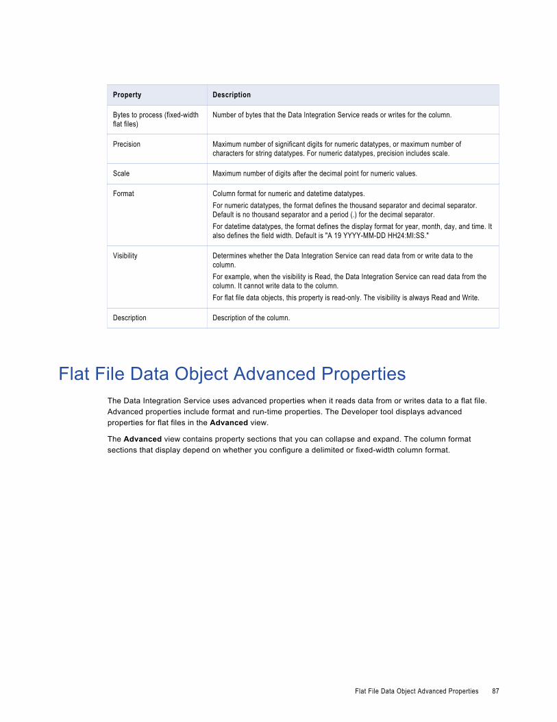
Property Description
Bytes to process (fixed-width flat files)
Number of bytes that the Data Integration Service reads or writes for the column.
Precision Maximum number of significant digits for numeric datatypes, or maximum number of characters for string datatypes. For numeric datatypes, precision includes scale.
Scale Maximum number of digits after the decimal point for numeric values.
Format Column format for numeric and datetime datatypes.For numeric datatypes, the format defines the thousand separator and decimal separator. Default is no thousand separator and a period (.) for the decimal separator.For datetime datatypes, the format defines the display format for year, month, day, and time. It also defines the field width. Default is "A 19 YYYY-MM-DD HH24:MI:SS."
Visibility Determines whether the Data Integration Service can read data from or write data to the column.For example, when the visibility is Read, the Data Integration Service can read data from the column. It cannot write data to the column.For flat file data objects, this property is read-only. The visibility is always Read and Write.
Description Description of the column.
Flat File Data Object Advanced PropertiesThe Data Integration Service uses advanced properties when it reads data from or writes data to a flat file. Advanced properties include format and run-time properties. The Developer tool displays advanced properties for flat files in the Advanced view.
The Advanced view contains property sections that you can collapse and expand. The column format sections that display depend on whether you configure a delimited or fixed-width column format.
Flat File Data Object Advanced Properties 87

The following image shows the property sections in the Advanced view:
Format PropertiesThe Developer tool displays format properties for flat file data objects in the Format section in the Advanced view.
The following table describes the format properties that you configure for flat file data objects:
Property Description
Code page Code page of the flat file data object.For source files, use a source code page that is a subset of the target code page. For lookup files, use a code page that is a superset of the source code page and a subset of the target code page. For target files, use a code page that is a superset of the source code pageDefault is "MS Windows Latin 1 (ANSI), superset of Latin 1."
Datetime format Defines the display format and the field width for datetime values.Default is "A 19 YYYY-MM-DD HH24:MI:SS."
Thousand separator Thousand separator for numeric values.Default is None.
Decimal separator Decimal separator for numeric values.Default is a period (.).
Column Format Format for the flat file, either delimited or fixed-width.
88 Chapter 6: Flat File Data Objects

Column Format: Delimited PropertiesWhen the flat file is delimited, the Developer tool displays delimited properties in the Column Format: Delimited section in the Advanced view.
The following table describes the delimited properties that you configure for flat file data objects:
Property Description
Delimiters Character used to separate columns of data.Click the Delimiters field to select a character or to assign a parameter to the property. Delimiters must be printable characters and must be different from the text qualifier and the escape character if selected.Default is Comma.
Text qualifier Quote character that defines the boundaries of text strings. If you select a quote character, the Developer tool ignores delimiters within a pair of quotes.Default is No Quotes.
Start import at line Row at which the Data Integration Service starts importing data. Use this option to skip header rows.Default is 1.
Row delimiter Octal code for the character that separates rows of data.Default is line feed, \012 LF (\n).
Escape character Character used to escape a delimiter character in an unquoted string if the delimiter is the next character after the escape character. If you specify an escape character, the Data Integration Service reads the delimiter character as a regular character embedded in the string.Note: You can improve mapping performance slightly if the source file does not contain quotes or escape characters.
Retain escape character in data
Includes the escape character in the output string.Default is disabled.
Treat consecutive delimiters as one
Causes the Data Integration Service to treat one or more consecutive column delimiters as one. Otherwise, the Data Integration Service reads two consecutive delimiters as a null value.Default is disabled.
Column Format: Fixed-width PropertiesWhen the flat file is fixed-width, the Developer tool displays fixed-width properties in the Column Format: Fixed-width section in the Advanced view.
The following table describes the fixed-width properties that you configure for flat file data objects:
Property Description
Null character type Null character type, either text or binary.
Null character value Character used to represent a null value. The null character can be any valid character in the file code page or any binary value from 0 to 255.
Flat File Data Object Advanced Properties 89

Property Description
Repeat null character For source files, causes the Data Integration Service to read repeat null characters in a single field as one null value.For target files, causes the Data Integration Service to write as many null characters as possible into the target field. If you do not enable this option, the Data Integration Service enters one null character at the beginning of the field to represent a null value.Default is disabled.
Start import at line Row at which the Data Integration Service starts importing data. Use this option to skip header rows.Default is 1.
Number of bytes to skip between records
Number of bytes between the last column of one row and the first column of the next. The Data Integration Service skips the entered number of bytes at the end of each row to avoid reading carriage return characters or line feed characters.Enter 1 for UNIX files and 2 for DOS files.Default is 2.
Line sequential Causes the Data Integration Service to read a line feed character or carriage return character in the last column as the end of the column. Select this option if the file uses line feeds or carriage returns to shorten the last column of each row.Default is disabled.
Strip trailing blanks Strips trailing blanks from string values.Default is disabled.
User defined shift state Allows you to select the shift state for source columns in the Columns properties.Select this option when the source file contains both multibyte and single-byte data, but does not contain shift-in and shift-out keys. If a multibyte file source does not contain shift keys, you must select a shift key for each column in the flat file data object. Select the shift key for each column to enable the Data Integration Service to read each character correctly.Default is disabled.
90 Chapter 6: Flat File Data Objects

Run-time: Read PropertiesThe Developer tool displays run-time properties for flat file sources in the Run-time: Read section in the Advanced view. The Data Integration Service uses this information when it reads data from a flat file.
The following table describes the read properties that you configure for flat file data objects:
Property Description
Input type Type of source input. You can choose the following types of source input:- File. For flat file sources.- Command. For source data or a file list generated by a shell command.
Source type Indicates source type of files with the same file properties. You can choose one of the following source types:- Direct. A source file that contains the source data.- Indirect. A source file that contains a list of files. The Data Integration Service reads the file
list and reads the files in sequential order.- Directory. Source files that are in a directory. You must specify the directory location in the
source file directory property. The Data Integration Service reads the files in ascending alphabetic order. The Data Integration Service does not read files in the subdirectories.
Source file name File name of the flat file source.
Source file directory Directory where the flat file sources exist. The machine that hosts Informatica services must be able to access this directory.Default is the SourceDir system parameter.
Concurrent Read Partitioning Order in which multiple partitions read input rows from a source file. If the Data Integration Service does not create partitions for the mapping, it ignores this value.Select one of the following options:- Optimize throughput. The Data Integration Service does not preserve input row order.- Keep relative order. The Data Integration Service preserves the input row order for the rows
read by each partition.- Keep absolute order. The Data Integration Service preserves the input row order for all
rows read by all partitions.
Connection Type The type of connection. Select from the following options:- None. The source file does not require a connection.- Hadoop File System. The source file resides in HDFS.Default is None.
Command Command used to generate the source file data. Use a command to generate or transform flat file data and send the standard output of the command to the flat file reader when the mapping runs. The flat file reader reads the standard output as the flat file source data. Generating source data with a command eliminates the need to stage a flat file source.Use a command or script to send source data directly to the Data Integration Service instead of using a pre-mapping command to generate a flat file source. You can also use a command to generate a file list.For example, to use a directory listing as a file list, use the following command:
cd MySourceFiles; ls sales-records-Sep-*-2005.dat
Truncate string null Strips the first null character and all characters after the first null character from string values.Enable this option for delimited flat files that contain null characters in strings. If you do not enable this option, the Data Integration Service generates a row error for any row that contains null characters in a string.Default is disabled.
Flat File Data Object Advanced Properties 91

Property Description
Line sequential buffer length Number of bytes that the Data Integration Service reads for each line.This property, together with the total row size, determines whether the Data Integration Service drops a row. If the row exceeds the larger of the line sequential buffer length or the total row size, the Data Integration Service drops the row and writes it to the mapping log file. To determine the total row size, add the column precision and the delimiters, and then multiply the total by the maximum bytes for each character.Default is 1024.
Generate Run-time Column Names
Determines how to generate the column metadata at run time.Select one of the following options:- Automatically (Field1, Field 2…). The Data Integration Service includes column metadata
based on the position of the column in the data. The column metadata for the flat file is constructed at run time from the row that the user specifies in the start from import line attribute in the format properties of the flat file data object.
- From data file header (first line). The first row of the flat file contains a header row that the Data Integration Service uses to determine the column metadata.
- From control file. The Data Integration Service constructs column metadata based on the data in a control file, such as column name, precision, data type, scale, and number of bytes to process.
Control file name Name of the control file. Required if you generate run-time column names from control file.
Control file directory Directory where the control file exist. Required if you generate run-time column names from control file.
Default Field Type Data type of the additional ports generated at run time.
Default Precision Precision of the additional ports generated at run time.
Default Scale Scale of the additional ports generated at run time.
Constraints Conditional expression that the values on a data row must satisfy. Use the Expression editor to enter an expression that evaluates to TRUE. When the Data Integration Service reads constraints, it drops the rows that do not evaluate to TRUE.For example, a source flat file has an AGE column. You can set a constraint with AGE < 70 on the flat file data object. The Data Integration Service reads rows from the source flat file with the constraint AGE < 70. If the Data Integration Service reads rows with AGE >= 70, it drops those rows.
92 Chapter 6: Flat File Data Objects

Run-time: Write PropertiesThe Developer tool displays run-time properties for flat file targets in the Run-time: Write section in the Advanced view. The Data Integration Service uses this information when it writes data to a flat file.
The following table describes the write properties that you configure for flat file data objects:
Property Description
Append if exists Appends the output data to the target files and reject files.If you do not select this option, the Data Integration Service truncates the target file and reject file before writing data to them. If the files do not exist, the Data Integration Service creates them.Default is disabled.
Create directory if not exists Creates the target directory if it does not exist.Default is disabled.
Header options Creates a header row in the file target. You can choose the following options:- No header. Does not create a header row in the flat file target.- Output field names. Creates a header row in the file target with the output port names .- Use header command output. Uses the command in the Header Command field to generate
a header row. For example, you can use a command to add the date to a header row for the file target.
Default is no header.
Header command Command used to generate the header row in the file target.
Footer command Command used to generate the footer row in the file target.
Output type Type of target for the mapping. Select File to write the target data to a flat file. Select Command to output data to a command.
Command Command used to process the target data.On UNIX, use any valid UNIX command or shell script. For example, use the following command to generate a compressed file from the target data on UNIX:
compress -c - > MyTargetFiles/MyCompressedFile.ZOn Windows, use any valid DOS command or batch file. The flat file writer sends the data to the command instead of a flat file target. For example, use cmd as the target command on Windows to avoid staging data in the file system and to avoid any security breaches.You can improve mapping performance by pushing transformation tasks to the command instead of the Data Integration Service. You can also use a command to sort or to compress target data.
Merge command Merge command used to process merge data for all target partitions. The Data Integration Service must use a concurrent merge type for a command to process merge data. The command might not maintain the order of the target data.
Output file directory Output directory for the flat file target. The machine that hosts Informatica services must be able to access this directory.Enter multiple directories separated by semicolons to increase performance when multiple partitions write to the flat file target.Default is the TargetDir system parameter.
Flat File Data Object Advanced Properties 93

Property Description
Output file name File name of the flat file target.If multiple partitions write to the flat file target and you choose not to merge target data, each partition writes to a separate output file named <output_file_name><partition_number>.out.
Merge type Type of merge that the Data Integration Service performs on the data for partitioned targets. If the Data Integration Service does not create partitions for the target, it ignores this value.Select one of the following options:- No merge. The Data Integration Service concurrently writes the target output to a separate
file for each partition.- Sequential. The Data Integration Service creates an output file for each partition and then
merges them into a single merge file at the end of the mapping.- File list. The Data Integration Service creates a target file for each partition and creates a
file list that contains the paths of the individual files.- Concurrent. The Data Integration Service concurrently writes the data for all target partitions
to the merge file. Because the Data Integration Service writes to the merge file concurrently for all partitions, the sort order of the data in the merge file might not be sequential.
Merge file directory Directory for the merge file for all target partitions. The machine that hosts Informatica services must be able to access this directory.Default is the TargetDir system parameter.
Merge file name Name of the merge file for all target partitions. Default is the output file name.
Connection type The type of connection. Select from the following options:- None. The target file does not require a connection. The target file location is specified by
the output file directory.- Hadoop File System. The target file is in HDFS.Default is None.
Control FileThe Data Integration Service can update the column metadata for the flat file based on a control file.
A control file is a simple text file with a field name, data type, precision, and scale. Each line in the control file contains one column of data.
To generate column names from a control file at run-time, select From control file for the Generate Run-time Column Names property in the Advanced properties of the flat file data object. You must also configure the Read transformation to get the column metadata at run time.
You can specify any of the following data types in the control file:
• Bigint
• Date/Time
• Decimal
• Double
• Integer
• String
94 Chapter 6: Flat File Data Objects

• Text
• TimestampwithTZ
You can use a control file to generate run-time column names for a Read transformation based on a flat file data object or to create a flat file data object. The Data Integration Service constructs the column metadata for the flat file by using the information present in the control file. The column name, precision, data type, and scale attributes are comma delimited. The newline character delimits information across columns.
Update Columns at Run TimeYou can configure a flat file data object to accommodate changes to source metadata at run time. The Data Integration Service can read data from a flat file where the number or order of the columns is different from that of the columns in the flat file physical data object.
For example, you have a mapping whose source is provided by another department. The department that provides the source cannot guarantee the order of columns in the source file. Sometimes, the department might change the columns in the file or contain additional columns. You can configure the flat file data object to accept changes in the source metadata at run time.
You can generate the run-time column names automatically from any row in the source, from the flat file header, or from the control file.
You can use input rules to project the run-time columns from the Read transformation based on the flat file data object to the next transformation in the mapping.
You can configure the Read transformation data object property to select At runtime, get data object columns from the data source on the Data Object tab. After you configure the property, the options in the flat file data object determine how the Data Integration Service processes the data.
Generate Run-time Column Names AutomaticallyThe Data Integration Service can update the column metadata for the flat file automatically based on the column position.
The Data Integration Service dynamically updates the column metadata for the flat file based on the row that you specify to start the import in the format properties of the flat file. The default data type, precision, and scale is used for the column metadata for the run-time columns without changing the column position.
To generate column names automatically at run time, select Automatically (Field1, Field 2...) for the Generate Run-time Column Names property in the Advanced properties of the flat file data object. You must also configure the Read transformation to get the column metadata at run time.
For example, you want to configure a flat file data object to accept changes at run time. The data in the flat file determines the column metadata based on the column position. You have defined a flat file data object with the columns Dept, Name, Place. You want the Data Integration Service to dynamically construct the column metadata for the flat file at run time.
The input file contains the following information:
HR,Bob,Chicago,US,87675Finance,Mary,California,US,65437,t567,4200
In the Format properties, you configured the flat file data object to start the import of data from line 1. Since there are five columns in the first row, the Data Integration Service processes the flat file data object with five columns. The Data Integration Service creates additional run-time columns in the flat file data object with
Update Columns at Run Time 95

unique names based on position, Field4 and Field5. The Data Integration Service does not process the additional columns in the second row.
When you add a flat file data object to a mapping, configure the Read transformation to get column metadata at run time. At run time, the Data Integration Service constructs the flat file data object and process the rows in the flat file with the following values:
Dept Name Place Field4 Field5HR Bob Chicago US 87675Finance Mary California US 65437
Generate Run-time Column Names From Data File HeaderThe Data Integration Service can use a header row to determine the column metadata. The first row of the flat file is the header.
The default data type, precision, and scale is used for the column metadata for the run-time columns and you can change the column position at run time.
To generate column names from a data file header at run-time, select From data file header (first line) for the Generate Run-time Column Names property in the Advanced properties of the flat file data object. You must also configure the Read transformation to get the column metadata at run time.
For example, you want to configure a flat file data object to accept changes at run time. The data in the flat file determines the column metadata based on the data file header.
You have defined a flat file data object with the columns Name,Age,Dept. You can configure the flat file data object advanced property to generate column names at run time from a data file header.
The data flat file contains the following information:
Dept Name Place Country Phone_No.HR Bob Chicago US 87675Finance Mary California US 65437 t567 4200
When you add a flat file data object to a mapping, configure the Read transformation to get column metadata at run time. During run time, the Data Integration Service generates the flat file data object with the following columns: Dept, Name, Place, Country and Phone_No. Since Age column is not present in the flat file header row, the flat file data object constructed at run time does not have the Age column.
The Data Integration Service propagates the run-time columns, such as Country and Phone Number to the downstream transformation based on the mapping rules.
Generate Column Metadata from Control FilesControl files are simple text files based on which you can create flat file data objects. You can also use control files to update columns at run time for a Read transformation based on a flat file data object.
When the Data Integration Service generates columns at run time, it uses the decimal and thousands separators specified in the flat file data object properties. You must specify only the name of the column in the control file if the column exists in the flat file data object.
When you specify the source type as indirect in the run-time properties in the Advanced view of the flat file source, you can generate column names at run time with the control file.
You can create a control file for a delimited or for a fixed-width flat file.
96 Chapter 6: Flat File Data Objects

You can parameterize the control file name and the control file directory in the run-time properties of the flat file data object.
The Data Integration Service processes a control file based on the column metadata that you specify in the control file and the input data.
When you generate column names from a control file at run time and the source data object contains the file name column, the Data Integration Service logs a validation error with the duplicate file names.
Control File FormatsDelimited and fixed-width flat files have different control file formats. You can use control files to generate column metadata at run time or to create a flat file data object.
Use one of the following formats to create a control file:
Delimited control file
Each line in a delimited control file has the following format:
[column name],<data type>,<precision>,<scale>The following example shows a delimited flat file control file:
Dept,String,10NamePlace,String,20CountryPhone number,string,30
Fixed-width control file
Each line in a fixed-width control file has the following format:
[column name],<data type>,<precision>,<scale>,<number of bytes to process>The following example shows a delimited flat file control file:
Dept,String,10NamePlace,String,20CountryPhone number,string,30
For a fixed-width source, the control file contains an additional column for the number of bytes to process. If you do not specify the number of bytes to process, the Data Integration Service uses the value specified for the precision as the number of bytes to process.
Parameterization of Run-time PropertiesYou can parameterize or specify values for the default scale, precision, and data type of the additional columns from the control file in the run-time properties of the flat file data object. You can parameterize the control file name and the control file directory in the run-time properties of the flat file data object. Configure the parameters on the Advanced tab of the physical data object properties. When you create the transformation from the physical data object, you can use mapping parameters to override the parameter default values.
Generate Column Metadata from Control Files 97
Run-time Processing of Control FilesWhen you develop a mapping, you define data object read properties that determine how data is read from a flat file. The Data Integration Service can process the columns of the flat file data object that is based on a control file.
When the Data Integration Service constructs the column metadata based on the control file, it applies the following criteria for processing data:The Data Integration Service applies default values for the column properties that you do not specify for the flat file data object
The Data Integration Service applies the default run-time properties of the flat file data object when you do not specify the run-time column properties in the control file. When you have additional columns in the control file without a data type, precision, or scale, the Data Integration Service uses the default data type, precision, and scale.
The Data Integration Service processes data as NULL for columns that do not appear in the control file but are present in the flat file data object
When the column in the flat file data object does not exist in the control file, the Data Integration Service processes the data as NULL during data preview. During run time, the Data Integration Service cannot process the column as that column does not exist in the control file.
The Data Integration Service fails mapping when the source metadata mismatches with a control file
The Data Integration Service fails to process the data when the source metadata based on the control file does not match the input data. For example, the Data Integration Service fails the mapping when the source contains a data type in the control file that is not compatible with the data type in the source.
Rules and Guidelines for Control FilesConsider the following guidelines when you use a control file:
• The control file must be accessible to the machine where the Data Integration Service runs.
• After you import a control file as a flat file data object, you cannot change the data type, precision, and scale of the columns in the data object. You can change the column position and column metadata for the additional columns from the control file.
• When you generate column names at run time based on the control file, the lookup cache reflects the metadata in the control file. If you update the same control file with additional columns after you run the mapping once, you must select the Recache from Lookup source property from the Runtime properties of the Lookup transformation.
• You cannot specify date format columns in the control file. The Data Integration Service uses the flat file date format from the flat file data object advanced properties in the Advanced view. If the flat file source contains multiple date formats, the Data Integration Service will use only the one date format specified in the Advanced view for all the dates.
• You cannot specify a binary data type in the control file. If the control file contains a TimestampwithTZ data type, ensure that the data type has the precision set to 36 and the scale set to 9 in the control file.
98 Chapter 6: Flat File Data Objects

Create a Flat File Data ObjectYou can create a flat file data object as an empty data object, from an existing flat file, or from a control file. You can create a delimited or fixed-width flat file data object using any method.
When you create a flat file data object, you can create the data object in the following ways:
As an empty data object
Create an empty flat file data object when you want to define the data object columns and rows in the Developer tool.
From an existing flat file
Create a flat file data object from an existing flat file when you have a flat file that defines the metadata you want to include in the data object.
From a control file
Create a flat file data object from a control file when you want to define the data object columns and rows based on a control file.
Creating an Empty Flat File Data ObjectCreate an empty flat file data object when you want to define the data object columns and rows in the Developer tool.
1. Select a project or folder in the Object Explorer view.
2. Click File > New > Data Object.
3. Select Physical Data Objects > Flat File Data Object and click Next.
The New Flat File Data Object dialog box appears.
4. Select Create as empty.
5. Enter a name for the data object.
6. Optionally, click Browse to select a project or folder for the data object.
7. Click Next.
8. Select a code page that matches the code page of the data that you want to process.
9. Select Delimited or Fixed-width.
10. If you selected Fixed-width, click Finish. If you selected Delimited, click Next.
11. Configure the following delimited format properties:
Property Description
Delimiters Character used to separate columns of data. If you enter a delimiter that is the same as the escape character or the text qualifier, you might receive unexpected results.
Text Qualifier Quote character that defines the boundaries of text strings. If you select a quote character, the Developer tool ignores delimiters within a pair of quotes.
12. Click Finish.
The empty data object opens in the editor. Define the columns for the data object in the Overview view.
Create a Flat File Data Object 99

Creating a Flat File Data Object from an Existing Flat FileCreate a flat file data object from an existing flat file when you have a flat file that defines the metadata you want to include in the data object.
1. Select a project or folder in the Object Explorer view.
2. Click File > New > Data Object.
3. Select Physical Data Objects > Flat File Data Object and click Next.
The New Flat File Data Object dialog box appears.
4. Select Create from an existing flat file.
5. Click Browse and navigate to the directory that contains the file.
6. Click Open.
The wizard names the data object the same name as the file you selected.
7. Optionally, edit the data object name.
8. Optionally, click Browse to select a project or folder for the data object.
9. Click Next.
10. Select a code page that matches the code page of the data that you want to process.
11. Select Delimited or Fixed-width.
12. Optionally, edit the maximum number of rows to preview.
13. Click Next.
14. Configure the format properties, based on whether the flat file is delimited or fixed-width.
• For a delimited flat file, configure the following properties:
Property Description
Delimiters Character used to separate columns of data. If you enter a delimiter that is the same as the escape character or the text qualifier, you might receive unexpected results.
Text Qualifier Quote character that defines the boundaries of text strings. If you select a quote character, the Developer tool ignores delimiters within pairs of quotes.
Import Column Names From First Line
If selected, the Developer tool uses data in the first row for column names. Select this option if column names appear in the first row. The Developer tool prefixes "FIELD_" to field names that are not valid.
Row Delimiter Specify a line break character. Select from the list or enter a character. Preface an octal code with a backslash (\). To use a single character, enter the character.The Data Integration Service uses only the first character when the entry is not preceded by a backslash. The character must be a single-byte character, and no other character in the code page can contain that byte. Default is line-feed, \012 LF (\n).
Escape Character Character immediately preceding a column delimiter character embedded in an unquoted string, or immediately preceding the quote character in a quoted string. When you specify an escape character, the Data Integration Service reads the delimiter character as a regular character.
100 Chapter 6: Flat File Data Objects

Property Description
Start Import at Line Row number at which the Data Integration Service starts reading when it imports the file. For example, if you specify to start at the second row, the Developer tool skips the first row before reading.
Treat Consecutive Delimiters as One
If selected, the Data Integration Service reads one or more consecutive column delimiters as one. Otherwise, the Data Integration Service reads two consecutive delimiters as a null value.
Retain Escape Character in Data
Includes the escape character in the output string.
• For a fixed-width flat file, configure the following properties:
Property Description
Import Column Names From First Line If selected, the Developer tool uses data in the first row for column names. Select this option if column names appear in the first row.
Start Import at Line Row number at which the Data Integration Service starts reading when it imports the file. For example, if you specify to start at the second row, the Developer tool skips the first row before reading.
Column breaks Configures the column breaks in the fixed-width file. Click Edit Breaks to edit column breaks. Or, follow the directions in the wizard to manipulate the column breaks in the file preview window. You can move column breaks by dragging them. Or, double-click a column break to delete it.
15. Click Next to preview the flat file data object.
16. Click Finish.
The data object opens in the editor.
Creating a Flat File Data Object from a Control FileCreate a flat file data object from a control file when you want to define the data object columns and rows based on a control file.
1. Select a project or folder in the Object Explorer view.
2. Click File > New > Data Object.
3. Select Physical Data Objects > Flat File Data Object and click Next.
The New Flat File Data Object dialog box appears.
4. Select Create from a control file.
5. Click Browse and navigate to the directory that contains the control file.
6. Click Open.
The wizard names the data object the same name as the control file you selected.
7. Optionally, edit the data object name.
8. Optionally, click Browse to select a project or folder for the data object.
9. Click Next.
10. Select a code page that matches the code page of the data that you want to process.
Create a Flat File Data Object 101

11. Select Delimited or Fixed-width.
12. If you selected Fixed-width, click Finish. If you selected Delimited, click Next.
13. Configure the following delimited format properties:
Property Description
Delimiters Character used to separate columns of data. If you enter a delimiter that is the same as the escape character or the text qualifier, you might receive unexpected results.
Text Qualifier Quote character that defines the boundaries of text strings. If you select a quote character, the Developer tool ignores delimiters within a pair of quotes.
14. Click Finish.
The data object opens in the editor.
102 Chapter 6: Flat File Data Objects

C H A P T E R 7
Logical View of DataThis chapter includes the following topics:
• Logical View of Data Overview, 103
• Developing a Logical View of Data, 104
• Logical Data Object Models, 105
• Logical Data Object Model Properties, 106
• Logical Data Objects, 113
• Logical Data Object Mappings, 117
Logical View of Data OverviewA logical view of data is a representation of data that resides in an enterprise. A logical view of data includes a logical data model, logical data objects, and logical data object mappings.
With a logical view of data, you can achieve the following goals:
• Use common data models across an enterprise so that you do not have to redefine data to meet different business needs. It also means if there is a change in data attributes, you can apply this change one time and use one mapping to make this change to all databases that use this data.
• Find relevant sources of data and present the data in a single view. Data resides in various places in an enterprise, such as relational databases and flat files. You can access all data sources and present the data in one view.
• Expose logical data as relational tables to promote reuse.
103

The following figure shows a sample of related logical data objects:
Logical Data Object Model ExampleCreate a logical data object model to describe the representation of logical entities in an enterprise. For example, create a logical data object model to present account data from disparate sources in a single view.
American Bank acquires California Bank. After the acquisition, American Bank has the following goals:
• Present data from both banks in a business intelligence report, such as a report on the top 10 customers.
• Consolidate data from both banks into a central data warehouse.
Traditionally, American Bank would consolidate the data into a central data warehouse in a development environment, verify the data, and move the data warehouse to a production environment. This process might take several months or longer. The bank could then run business intelligence reports on the data warehouse in the production environment.
A developer at American Bank can use the Developer tool to create a model of customer, account, branch, and other data in the enterprise. The developer can link the relational sources of American Bank and California bank to a single view of the customer. The developer can then make the data available for business intelligence reports before creating a central data warehouse.
Developing a Logical View of DataDevelop a logical view of data to represent how an enterprise accesses data and uses data.
After you develop a logical view of data, you can add it to a data service to make virtual data available for end users.Before you develop a logical view of data, you can define the physical data objects that you want to use in a logical data object mapping. You can also profile the physical data sources to analyze data quality.
1. Create or import a logical data model.
2. Optionally, add logical data objects to the logical data object model and define relationships between objects.
104 Chapter 7: Logical View of Data

3. Create a logical data object mapping to read data from a logical data object or write data to a logical data object. A logical data object mapping can contain transformation logic to transform the data. The transformations can include data quality transformations to validate and cleanse the data.
4. View the output of the logical data object mapping.
Logical Data Object ModelsA logical data object model describes the structure and use of data in an enterprise. The model contains logical data objects and defines relationships between them.
Define a logical data object model to create a unified model of data in an enterprise. The data in an enterprise might reside in multiple disparate source systems such as relational databases and flat files. A logical data object model represents the data from the perspective of the business regardless of the source systems. Create a logical data object model to study data, describe data attributes, and define the relationships among attributes.
For example, customer account data from American Bank resides in an Oracle database, and customer account data from California Banks resides in an IBM DB2 database. You want to create a unified model of customer accounts that defines the relationship between customers and accounts. Create a logical data object model to define the relationship.
You can import a logical data object model from a modeling tool. You can also import a logical data object model from an XSD file that you created in a modeling tool. Or, you can manually create a logical data object model in the Developer tool.
You add a logical data object model to a project or folder and store it in the Model repository.
To allow end users to run SQL queries against a logical data object, include it in an SQL data service. Make the logical data object the source for a virtual table. To allow end users to access a logical data object over the Web, include it in a web service. Make the logical data object the source for an operation.
Creating a Logical Data Object ModelCreate a logical data object model to define the structure and use of data in an enterprise. When you create a logical data object model, you can add logical data objects. You associate a physical data object with each logical data object. The Developer tool creates a logical data object read mapping for each logical data object in the model.
1. Select a project or folder in the Object Explorer view.
2. Click File > New > Logical Data Object Model.
The New dialog box appears.
3. Select Logical Data Object Model and click Next.
The New Logical Data Object Model dialog box appears.
4. Enter a name for the logical data object model.
5. To create logical data objects, click Next. To create an empty logical data object model, click Finish.
If you click Next, the Developer tool prompts you to add logical data objects to the model.
6. To create a logical data object, click the New button.
The Developer tool adds a logical data object to the list.
Logical Data Object Models 105

7. Enter a name in the Name column.
8. Optionally, click the Open button in the Data Object column to associate a physical data object with the logical data object.
The Select a Data Object dialog box appears.
9. Select a physical data object and click OK.
10. Repeat steps 6 through 9 to add logical data objects.
11. Click Finish.
The logical data object model opens in the editor.
Importing a Logical Data Object Model from a Modeling ToolYou can import a logical data object model from a modeling tool or an XSD file. Import a logical data object model to use an existing model of the structure and data in an enterprise.
1. Select the project or folder to which you want to import the logical data object model.
2. Click File > New > Logical Data Object Model.
The New Logical Data Object Model dialog box appears.
3. Select Logical Data Object Model from Data Model.
4. Click Next.
5. In the Model Type field, select the modeling tool from which you want to import the logical data object model.
6. Enter a name for the logical data object model.
7. Click Browse to select the location of the logical data object model.
8. Click Next.
9. Browse to the file that you want to import, select the file, and click Open.
10. Configure the import properties.
11. Click Next.
12. Add logical data objects to the logical data object model.
13. Click Finish.
The logical data objects appear in the editor.
Logical Data Object Model PropertiesWhen you import a logical data object model from a modeling tool, provide the properties associated with the tool.
106 Chapter 7: Logical View of Data

CA ERwin Data Modeler Import PropertiesConfigure the import properties when you import a logical data object model from CA ERwin Data Modeler.
The following table describes the properties to configure when you import a model from CA ERwin Data Modeler:
Property Description
Import UDPs Specifies how to import user-defined properties.Select one of the following options:- As metadata. Import an explicit value as the property value object. Explicit values
are not exported.- As metadata, migrate default values. Import explicit and implicit values as
property value objects.- In description, migrate default values. Append the property name and value, even
if implicit, to the object description property.- Both, migrate default values. Import the UDP value, even if implicit, both as
metadata and in the object's description.Default is As metadata.
Import relationship name Specifies how to import the relationship names from ERwin.Select one of the following options:- From relationship name- From relationship descriptionDefault is From relationship name.
Import IDs Specifies whether to set the unique ID of the object as the NativeId property.
Import subject areas Specifies how to import the subject areas from ERwin.Select one of the following options:- As diagrams- As packages and diagrams- As packages and diagrams, assuming one subject area for each entity- Do not import subject areasDefault is As diagrams.
Import column order form Specifies how to import the position of columns in tables.Select one of the following options:- Column order. Order of the columns displayed in the ERwin physical view.- Physical order. Order of the columns in the database, as generated in the SQL
DDL.Default is Physical order.
Import owner schemas Specifies whether to import owner schemas.
Logical Data Object Model Properties 107

IBM Cognos Business Intelligence Reporting - Framework Manager Import Properties
Configure the import properties when you import a logical data object model from IBM Cognos Business Intelligence Reporting - Framework Manager.
The following table describes the properties to configure when you import a model from IBM Cognos Business Intelligence Reporting - Framework Manager:
Property Description
Folder Representation Specifies how to represent folders from the Framework Manager.Select one of the following options:- Ignore. Ignore folders.- Flat. Represent folders as diagrams but do not preserve hierarchy.- Hierarchial. Represent folders as diagrams and preserve hierarchy.Default is Ignore.
Package Representation Specifies how to represent packages from Cognos Framework Manager.Select one of the following options:- Ignore. Ignore subject areas.- Subject Areas. Represent packages as subject areas.- Model. Represent the package as the model.Default is Ignore.
Reverse engineer relationships Specifes whether the Developer tool computes the relationship between two dbQueries as referential integrity constraints.
Tables design level Specifies how to control the design level of the imported tables:Select one of the following options:- Logical and physical. The tables appear in both the logical view and in the
physical view of the model.- Physical. The tables appear only in the physical view of the model.Default is Physical.
Ignore usage property Specify whether the usage property of a queryItem should be used.
108 Chapter 7: Logical View of Data

SAP BusinessObjects Designer Import PropertiesConfigure the import properties when you import a logical data object model from SAP BusinessObjects Designer.
The following table describes the properties to configure when you import a model from SAP BusinessObjects Designer:
Property Description
System Name of the BusinessObjects repository.For BusinessObjects versions 11.x and 12.x (XI), enter the name of the Central Management Server. For BusinessObjects version 5.x and 6.x, enter name of the repository defined by the Supervisor application
Authentication mode Login authentication mode.This parameter is applicable to SAP BusinessObjects Designer 11.0 and later.Select one of the following authentication modes:- Enterprise. Business Objects Enterprise login- LDAP. LDAP server authentication- Windows AD. Windows Active Directory server authentication- Windows NT. Windows NT domain server authentication- Standalone. Standalone authenticationDefault is Enterprise.
User name User name in the BusinessObjects server. For version 11.x and 12.x (XI), you need to be a member of BusinessObjects groups.
Password Password for the BusinessObjects server.
Silent execution Specifies whether to execute in interactive or silent mode.Default is Silent.
Close after execution Specify whether to close BusinessObjects after the Developer Tool completes the model import.
Table design level Specifies the design level of the imported tables.Select one of the following options:- Logical and physical. The tables appear both in the logical view and in the
physical view of the model.- Physical. The tables appear both in the physical view of the model.Default is Physical.
Transform Joins to Foreign Keys Transforms simple SQL joins in the model into foreign key relationships.Select the parameter if you want to export the model to a tool that only supports structural relational metadata, such as a database design tool.
Class representation Specifies how to import the tree structure of classes and sub-classes. The Developer Tool imports each class as a dimension as defined by the CWM OLAP standard. The Developer Tool also imports classes and sub-classes as a tree of packages as defined by the CWM and UML standards.Select one of the following options:- As a flat structure. The Developer tool does not create package.- As a simplified tree structure. The Developer tool creates package for each class
with sub-classes.- As a full tree structure. The Developer tool creates a package for each class.Default is As a flat structure.
Logical Data Object Model Properties 109

Property Description
Include List of Values Controls how the Developer tool imports the list of values associated with objects.
Dimensional properties transformation Specifies how to transfer the dimension name, description, and role to the underlying table and the attribute name, description, and datatype to the underlying column.Select one of the following options:- Disabled. No property transfer occurs.- Enabled. Property transfer occurs where there are direct matches between the
dimensional objects and the relational objects. The Developer tool migrates the dimension names to the relational names.
- Enabled (preserve names). Property transfer occurs where there are direct matches between the dimensional objects and the relational objects. The Developer tool preserves the relational names.
Default is Disabled.
SAP PowerDesigner CDM Import PropertiesConfigure the import properties when you import a logical data object model from SAP PowerDesigner CDM.
The following table describes the properties to configure when you import a model from SAP PowerDesigner CDM:
Property Description
Import UDPs Specifies how to import user-defined properties.Select one of the following options:- As metadata. Import an explicit value as the property value object. Explicit
values are not exported.- As metadata, migrate default values. Import explicit and implicit values as
property value objects.- In description, migrate default values. Append the property name and value,
even if implicit, to the object description property.- Both, migrate default values. Import the UDP value, even if implicit, both as
metadata and in the object's description.Default is As metadata.
Import Association Classes Specifies whether the Developer tool should import association classes.
Import IDs Specifies whether to set the unique ID of the object as the NativeId property.
Append volumetric information to the description field
Import and append the number of occurrences information to the description property.
Remove text formatting Specifies whether to remove or keep rich text formatting.Select this option if the model was generated by PowerDesigner 7.0 or 7.5Clear this option if the model was generated by PowerDesigner 8.0 or greater.
110 Chapter 7: Logical View of Data

SAP PowerDesigner OOM 9.x to 15.x Import PropertiesConfigure the import properties when you import a logical data object model from SAP PowerDesigner OOM 9.x to 15.x.
When you import a logical data object model from SAP PowerDesigner OOM, the Developer tool imports the classes and attributes but leaves out other entities. To import a logical data object model, export the model from SAP PowerDesigner in the UML 1.3 - XMI 1.0 XML format.
The following table describes the properties to configure when you import a model from SAP PowerDesigner OOM:
Property Description
Target Tool Specifies which tool generated the model you want to import.Select one of the following options:- Auto Detect. The Developer tool detects which tool generated the file.- OMG XMI. The file conforms to the OMG XMI 1.0 standard DTDs.- Argo/UML 0.7. The file was generated by Argo/UML 0.7.0 or earlier.- Argo/UML 0.8. The file was generated by Argo/UML 0.7.1 or later.- XMI Toolkit. The file was generated by IBM XMI Toolkit.- XMI Interchange. The file was generated by Unisys Rose XMI Interchange.- Rose UML. The file was generated by Unisys Rose UML.- Visio UML. The file was generated by Microsoft Visio Professional 2002 and Visio
for Enterprise Architects using UML to XMI Export.- PowerDesigner UML. The file was generated by Sybase PowerDesigner using XMI
Export.- Component Modeler. The file was generated by CA AllFusion Component Modeler
using XMI Export.- Netbeans XMI Writer. The file was generated by one of applications using
Netbeans XMI Writer such as Poseidon.- Embarcadero Describe. The file was generated by Embarcadero Describe.Default is Auto Detect.
Auto Correct Fix and import an incomplete or incorrect model in the XML file.
Model Filter Model to import if the XML file contains more than one model. Use a comma to separate multiple models.
Top Package The top-level package in the model.
Import UUIDs Import UUIDs as NativeId.
Logical Data Object Model Properties 111

SAP PowerDesigner PDM Import PropertiesConfigure the import properties when you import a logical data object model from SAP PowerDesigner PDM.
The following table describes the properties to configure when you import a model from SAP PowerDesigner PDM:
Property Description
Import UDPs Specifies how to import user-defined properties.Select one of the following options:- As metadata. Import an explicit value as the property value object. Explicit
values are not exported.- As metadata, migrate default values. Import explicit and implicit values as
property value objects.- In description, migrate default values. Append the property name and value,
even if implicit, to the object description property.- Both, migrate default values. Import the UDP value, even if implicit, both as
metadata and in the object's description.Default is As metadata.
Import IDs Specifies whether to set the unique id of the object as the NativeId property.
Append volumetric information to the description field
Import and append the number of occurrences information to the description property.
Remove text formatting Specifies whether to remove or keep rich text formatting.Select this option if the model was generated by PowerDesigner 7.0 or 7.5Clear this option if the model was generated by PowerDesigner 8.0 or greater.
XSD Import PropertiesYou can import logical data object models from an XSD file exported by a modeling tool.
The following table describes the properties to configure when you import a model from an XSD file:
Property Description
Elements content name Attribute to hold the textual content like #PCDATA in the XSD file.Default is As metadata.
Collapse Level Specifies when to collapse a class. The value you select determines whether the Developer tool imports all or some of the elements and attributes in the XSD file.Select one of the following options:- None. Every XSD element becomes a class and every XSD attribute becomes
an attribute.- Empty. Only empty classes collapse into the parent classes.- Single Attribute. Only XSD elements with a single attribute and no children
collapse into the parent class.- No Children. Any XSD element that has no child element collapse into the parent
class.- All. All collapsible XSD elements collapse into the parent class.Default is All.
Collapse Star Specifies whether the Developer tool should collapase XML elements with an incoming xlink into the parent class.
112 Chapter 7: Logical View of Data
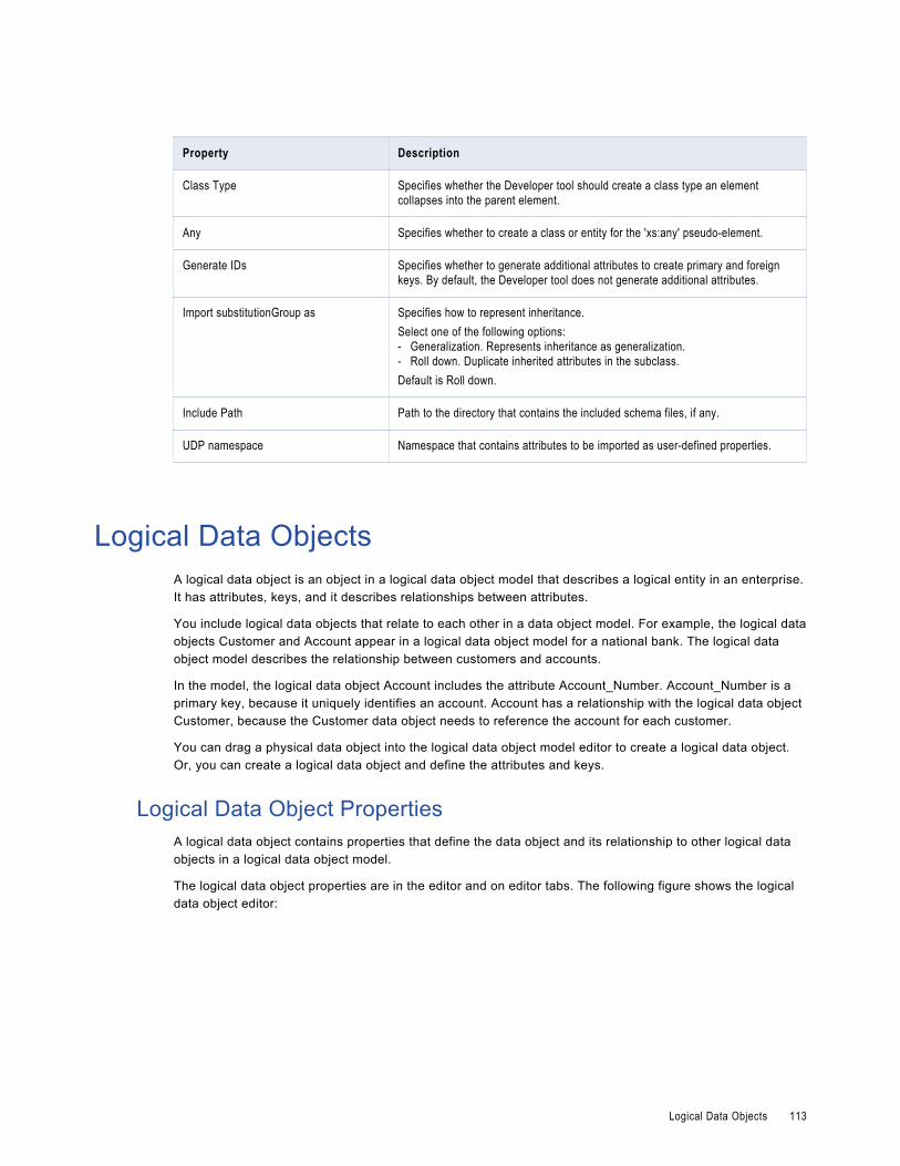
Property Description
Class Type Specifies whether the Developer tool should create a class type an element collapses into the parent element.
Any Specifies whether to create a class or entity for the 'xs:any' pseudo-element.
Generate IDs Specifies whether to generate additional attributes to create primary and foreign keys. By default, the Developer tool does not generate additional attributes.
Import substitutionGroup as Specifies how to represent inheritance.Select one of the following options:- Generalization. Represents inheritance as generalization.- Roll down. Duplicate inherited attributes in the subclass.Default is Roll down.
Include Path Path to the directory that contains the included schema files, if any.
UDP namespace Namespace that contains attributes to be imported as user-defined properties.
Logical Data ObjectsA logical data object is an object in a logical data object model that describes a logical entity in an enterprise. It has attributes, keys, and it describes relationships between attributes.
You include logical data objects that relate to each other in a data object model. For example, the logical data objects Customer and Account appear in a logical data object model for a national bank. The logical data object model describes the relationship between customers and accounts.
In the model, the logical data object Account includes the attribute Account_Number. Account_Number is a primary key, because it uniquely identifies an account. Account has a relationship with the logical data object Customer, because the Customer data object needs to reference the account for each customer.
You can drag a physical data object into the logical data object model editor to create a logical data object. Or, you can create a logical data object and define the attributes and keys.
Logical Data Object PropertiesA logical data object contains properties that define the data object and its relationship to other logical data objects in a logical data object model.
The logical data object properties are in the editor and on editor tabs. The following figure shows the logical data object editor:
Logical Data Objects 113

The following table describes information that appears in the logical data object editor:
Tab Name Description
Overview The General area includes the object name, description, and read and write mapping if applicable, of the logical data object.The Attributes area displays the structure of data in a logical data object.
Keys One or more attributes in a logical data object can be primary keys or unique keys.
Relationships Associations between logical data objects.
Access Type of access for a logical data object and each attribute of the data object.
Read Mapping Logical data object read mapping associated with a logical data object. If the logical data object contains no read mapping, the Read Mapping tab is not visible.
Write Mapping Logical data object write mapping associated with a logical data object. If the logical data object contains no write mapping,the Write Mapping tab is not visible.
Attribute RelationshipsA relationship is an association between primary or foreign key attributes of one or more logical data objects.
You can define the following types of relationship between attributes:Identifying
A relationship between two attributes where an attribute is identified through its association with another attribute.
For example, the relationship between the Branch_ID attribute of the logical data object Branch and the Branch_Location attribute of the logical data object Customer is identifying. This is because a branch ID is unique to a branch location.
114 Chapter 7: Logical View of Data

Non-Identifying
A relationship between two attributes that identifies an attribute independently of the other attribute.
For example, the relationship between the Account_Type attribute of the Account logical data object and the Account_Number attribute of the Customer logical data object is non-identifying. This is because you can identify an account type without having to associate it with an account number.
When you define relationships, the logical data object model indicates an identifying relationship as a solid line between attributes. It indicates a non-identifying relationship as a dotted line between attributes.
Creating a Logical Data ObjectYou can create a logical data object in a logical data object model to define a logical entity in an enterprise.
1. Click File > New > Logical Data Object.
2. Enter a logical data object name.
3. Select the logical data object model for the logical data object and click Finish.
The logical data object appears in the logical data object model editor.
4. Select the logical data object and click the Properties view.
5. On the Overview tab in the General area, you can optionally edit the logical data object name and description.
6. On the Overview tab in the Attributes area, you can create attributes and specify their datatype and precision.
Logical Data Objects 115

7. On the Keys tab, optionally specify primary and unique keys for the data object.
8. On the Relationships tab, optionally create relationships between logical data objects.
9. On the Access tab, optionally edit the type of access for the logical data object and each attribute in the data object.
116 Chapter 7: Logical View of Data

Default is read only.
10. On the Read Mapping tab, optionally create a logical data object read mapping.
11. On the Write Mapping tab, optionally create a logical data object write mapping.
12. Save the logical data object.
Logical Data Object MappingsA logical data object mapping is a mapping that links a logical data object to one or more physical data objects. It can include transformation logic.
A logical data object mapping can be of the following types:
• Read
• Write
You can associate each logical data object with one logical data object read mapping or one logical data object write mapping.
Logical Data Object Mappings 117

Logical Data Object Read MappingsA logical data object read mapping contains one or more physical data objects as input and one logical data object as output. The mapping can contain transformation logic to transform the data.
It provides a way to access data without accessing the underlying data source. It also provides a way to have a single view of data coming from more than one source.
For example, American Bank has a logical data object model for customer accounts. The logical data object model contains a Customers logical data object.
American Bank wants to view customer data from two relational databases in the Customers logical data object. You can use a logical data object read mapping to perform this task and view the output in the Data Viewer view.
Logical Data Object Write MappingsA logical data object write mapping contains a logical data object as input. It provides a way to write to targets from a logical data object.
The mapping can contain transformation logic to transform the data. The mapping runs without accessing the underlying data target. It provides a single view of the transformed data without writing to the target.
Creating a Logical Data Object MappingYou can create a logical data object mapping to link data from a physical data object to a logical data object and transform the data.
1. In the Object Explorer view, double-click the logical data object that you want to add the mapping to.
The logical data object editor opens.
2. On the Overview tab in the General area, click Add to add a read mapping or a write mapping.
The following image shows the Add button:
3. Enter a name for the mapping, and then click Finish.
118 Chapter 7: Logical View of Data

The editor displays the logical data object as the mapping input or output, based on whether the mapping is a read or write mapping.
4. Link data from a physical data object to the logical data object.
a. Click the Read Mapping or Write Mapping tab to edit the mapping.
The mapping editor palette opens.
b. In the Object Explorer view, browse to the physical data object you want to link, and drag the physical data object into the mapping editor palette.
The Add to Mapping dialog box opens.
c. Choose to create a read mapping, write mapping, or lookup mapping.
d. If you chose to create a read mapping, designate the object access of the read mapping as a related data object or as an independent data object.
e. Click OK.
The following image shows the result after a user drags the customer flat file data object to the mapping editor palette and designates it a read mapping.
5. Optionally, add a reusable object to the mapping.
You can add a logical data object or other Model repository object.
a. Right-click in the mapping editor and select Add Reusable Object.
b. Select one of the objects from the Model repository, and click OK.
c. Choose to designate the reusable object a Read mapping, Write mapping, or Lookup mapping.
d. If you chose to designate the reusable object a Read mapping, designate the object access of the Read mapping as a related data object or as an independent data object.
e. Click OK.
6. Optionally, add additional objects and transformations to the mapping, and create links between mapping objects, then click the Data Viewer view and run the mapping.
Results appear in the Output section.
Logical Data Object Mappings 119

C H A P T E R 8
Viewing DataThis chapter includes the following topics:
• Viewing Data Overview, 120
• Configurations, 121
• Exporting Data, 128
• Object Dependencies, 128
• Logs, 130
• Validation Preferences, 131
• Monitoring Jobs from the Developer Tool, 132
Viewing Data OverviewYou can run a mapping, view profile results, view source data, preview data for a transformation, run an SQL query, preview web service messages, or view dependencies on an object.
Run a mapping to move output from sources to targets and transform data. You can run a mapping from the command line or from the Run dialog box. View profile results in the editor.
You view source data, preview data for a transformation, run an SQL query, or preview web service messages in the Data Viewer view.
Note: The maximum number of rows you can preview in the Data Viewer is 100,000.
Before you can view data, you must select the default Data Integration Service. You can also add other Data Integration Services to use when you view data. You can create configurations to control settings that the Developer tool applies when you view data.
When you view data in the Data Viewer view, you can export the data to a file. You can also access logs that show log events.
You can also view object dependencies when you view, modify, or delete Model repository objects. You can view object dependencies in the Object Dependencies view.
120

ConfigurationsA configuration is a group of settings that the Developer tool applies when you run a mapping, preview data, run an SQL query, or preview web service messages.
A configuration controls settings such as the default Data Integration Service, number of rows to read from a source, default date/time format, and optimizer level. The configurations that you create apply to your installation of the Developer tool.
You can create the following configurations:
• Data viewer configurations. Control the settings the Developer tool applies when you preview output in the Data Viewer view.
• Mapping configurations. Control the settings the Developer tool applies when you run mappings through the Run Configurations dialog box or from the command line.
• Web service configurations. Controls the settings that the Developer tool applies when you preview the output of a web service in the Data Viewer view.
Configuration PropertiesThe Developer tool applies configuration properties when you preview output or you run mappings. Set configuration properties for the Data Viewer view or mappings in the Run dialog box.
Data Integration Service PropertiesThe Developer tool displays the Data Integration Service tab for data viewer, mapping, and web service configurations.
The following table displays the properties that you configure for the Data Integration Service:
Property Description
Use default Data Integration Service
Uses the default Data Integration Service to run the mapping.Default is enabled.
Data Integration Service Specifies the Data Integration Service that runs the mapping if you do not use the default Data Integration Service.
Available OS profiles Specifies the operating system profile to run the mapping when the Data Integration Service is enabled to use operating system profiles.The Developer tool displays this property only if the administrator assigned at least one operating system profile to the user. The Data Integration Service runs the mapping with the default operating system profile assigned to the user. You can change the operating system profile from the list of available operating system profiles.
Configurations 121

Source PropertiesThe Developer tool displays the Source tab for data viewer, mapping, and web service configurations.
The following table displays the properties that you configure for sources:
Property Description
Read all rows Reads all rows from the source.Default is enabled.
Read up to how many rows Specifies the maximum number of rows to read from the source if you do not read all rows.Note: If you enable the this option for a mapping that writes to a customized data object, the Data Integration Service does not truncate the target table before it writes to the target.Default is 1000.
Read all characters Reads all characters in a column.Default is disabled.
Read up to how many characters
Specifies the maximum number of characters to read in each column if you do not read all characters. The Data Integration Service ignores this property for SAP sources.Default is 4000.
Results PropertiesThe Developer tool displays the Results tab for data viewer and web service configurations.
The following table displays the properties that you configure for results in the Data Viewer view:
Property Description
Show all rows Displays all rows in the Data Viewer view.Default is disabled.
Show up to how many rows Specifies the maximum number of rows to display if you do not display all rows.Default is 1000.
Show all characters Displays all characters in a column.Default is disabled.
Show up to how many characters
Specifies the maximum number of characters to display in each column if you do not display all characters.Default is 4000.
122 Chapter 8: Viewing Data

Messages PropertiesThe Developer tool displays the Messages tab for web service configurations.
The following table displays the properties that you configure for messages:
Property Description
Read up to how many characters for request message
Specifies the maximum number of characters to process in the input message.
Show up to how many characters for response message
Specifies the maximum number of characters to display in the output message.
Advanced PropertiesThe Developer tool displays the Advanced tab for data viewer, mapping, and web service configurations.
The following table displays the advanced properties:
Property Description
Default date time format Date/time format the Data Integration Services uses when the mapping converts strings to dates.Default is MM/DD/YYYY HH24:MI:SS.
Override tracing level Overrides the tracing level for each transformation in the mapping. The tracing level determines the amount of information that the Data Integration Service sends to the mapping log files.Choose one of the following tracing levels:- None. The Data Integration Service uses the tracing levels set in the mapping.- Terse. The Data Integration Service logs initialization information, error messages, and
notification of rejected data.- Normal. The Data Integration Service logs initialization and status information, errors
encountered, and skipped rows due to transformation row errors. Summarizes mapping results, but not at the level of individual rows.
- Verbose initialization. In addition to normal tracing, the Data Integration Service logs additional initialization details, names of index and data files used, and detailed transformation statistics.
- Verbose data. In addition to verbose initialization tracing, the Data Integration Service logs each row that passes into the mapping. Also notes where the Data Integration Service truncates string data to fit the precision of a column and provides detailed transformation statistics.
Default is None.
Sort order Order in which the Data Integration Service sorts character data in the mapping.Default is Binary.
Configurations 123
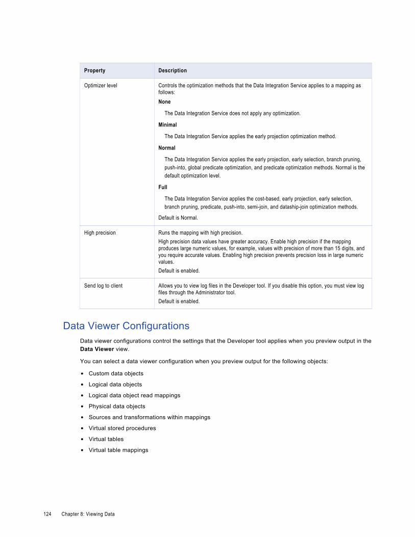
Property Description
Optimizer level Controls the optimization methods that the Data Integration Service applies to a mapping as follows:None
The Data Integration Service does not apply any optimization.
Minimal
The Data Integration Service applies the early projection optimization method.
Normal
The Data Integration Service applies the early projection, early selection, branch pruning, push-into, global predicate optimization, and predicate optimization methods. Normal is the default optimization level.
Full
The Data Integration Service applies the cost-based, early projection, early selection, branch pruning, predicate, push-into, semi-join, and dataship-join optimization methods.
Default is Normal.
High precision Runs the mapping with high precision.High precision data values have greater accuracy. Enable high precision if the mapping produces large numeric values, for example, values with precision of more than 15 digits, and you require accurate values. Enabling high precision prevents precision loss in large numeric values.Default is enabled.
Send log to client Allows you to view log files in the Developer tool. If you disable this option, you must view log files through the Administrator tool.Default is enabled.
Data Viewer ConfigurationsData viewer configurations control the settings that the Developer tool applies when you preview output in the Data Viewer view.
You can select a data viewer configuration when you preview output for the following objects:
• Custom data objects
• Logical data objects
• Logical data object read mappings
• Physical data objects
• Sources and transformations within mappings
• Virtual stored procedures
• Virtual tables
• Virtual table mappings
124 Chapter 8: Viewing Data

Creating a Data Viewer ConfigurationCreate a data viewer configuration to control the settings the Developer tool applies when you preview output in the Data Viewer view.
1. Click Run > Open Run Dialog.
The Run Configurations dialog box appears.
2. Click Data Viewer Configuration.
3.Click the New button( ).
Configurations 125

The right panel of the Run Configurations dialog box displays the data viewer configuration properties.
4. Enter a name for the data viewer configuration.
5. Configure the data viewer configuration properties.
6. Click Apply.
7. Click Close.
The Developer tool creates the data viewer configuration.
Mapping ConfigurationsMapping configurations control the mapping deployment properties that the Developer tool uses when you run a mapping through the Run Configurations dialog box or from the command line.
To apply a mapping configuration to a mapping that you run through the Developer tool, you must run the mapping through the Run Configurations dialog box. If you run the mapping through the Run menu or mapping editor, the Developer tool runs the mapping with the default mapping deployment properties.
To apply mapping deployment properties to a mapping that you run from the command line, select the mapping configuration when you add the mapping to an application. The mapping configuration that you select applies to all mappings in the application.
You can change the mapping deployment properties when you edit the application. An administrator can also change the mapping deployment properties through the Administrator tool. You must redeploy the application for the changes to take effect.
126 Chapter 8: Viewing Data

Creating a Mapping ConfigurationCreate a mapping configuration to control the mapping deployment properties that the Developer tool uses when you run mappings through the Run dialog box or from the command line.
1. Click Run > Open Run Dialog.
The Run Configurations dialog box appears.
2. Click Mapping Configuration.
3. Click the New button.
The right panel of the Run Configurations dialog box displays the mapping configuration properties.
4. Enter a name for the mapping configuration.
5. Configure the mapping configuration properties.
6. Click Apply.
7. Click Close.
The Developer tool creates the mapping configuration.
Web Service ConfigurationsWeb Service configurations control the settings that the Developer tool applies when you preview the output of a web service in the Data Viewer view.
Create a web service configuration to control the setting that you want to use for specific web services. You can select a web service configuration when you preview the output of an operation mapping or transformations in an operation mapping.
Note: To create a web service configuration that applies to all web services that you preview, use the Preferences dialog box to update the default web service configuration.
Creating a Web Service ConfigurationCreate a web service configuration to control the settings the Developer tool applies when you preview the output of a web service in the Data Viewer view.
1. Click Run > Open Run Dialog.
The Run dialog box appears.
2. Click Web Service Configuration.
3. Click New.
4. Enter a name for the web service configuration.
5. Configure the web service configuration properties.
6. Click Apply.
7. Click Close.
Updating the Default Configuration PropertiesYou can update the default data viewer, mapping, and web service configuration properties.
1. Click Window > Preferences.
The Preferences dialog box appears.
Configurations 127

2. Click Informatica > Run Configurations.
3. Select the Data Viewer, Mapping, or Web Service configuration.
4. Configure the default data viewer, mapping, or web service configuration properties.
5. Click OK.
The Developer tool updates the default configuration properties.
Troubleshooting Configurations
I created two configurations with the same name but with different cases. When I close and reopen the Developer tool, one configuration is missing.Data viewer and mapping configuration names are not case sensitive. If you create multiple configurations with the same name but different cases, the Developer tool deletes one of the configurations when you exit. The Developer tool does not consider the configuration names unique.
I tried to create a configuration with a long name, but the Developer tool displays an error message that says it cannot not write the file.The Developer tool stores data viewer and mapping configurations in files on the machine that runs the Developer tool. If you create a configuration with a long name, for example, more than 100 characters, the Developer tool might not be able to save the file to the hard drive.
To work around this issue, shorten the configuration name.
Exporting DataYou can export the data that appears in the Data Viewer view to a tab-delimited flat file, such as a TXT or CSV file. Export data when you want to create a local copy of the data.
1. In the Data Viewer view, right-click the results and select Export Data.
2. Enter a file name and extension.
3. Select the location where you want to save the file.
4. Click OK.
Object DependenciesBefore you change or delete an object, you can view object dependencies for all objects in the Model repository that the object has an impact on. You can view object dependencies for all objects that are dependent on the object and objects that this object depends on.
For example, you want to delete a data object that is deployed in multiple applications. However, you do not know if deleting this data object has an impact on the deployed applications. You can view object dependencies to determine if this data object has an impact on the deployed applications. After you delete the data object, you can redeploy the applications.
You can see object dependencies in the Object Dependencies view. If a dependent object is in a project that you do not have permission to read, the Developer tool does not display the object in the Object
128 Chapter 8: Viewing Data
Dependencies view. The Developer tool displays a message that states the Developer tool cannot access the object.
View Object DependenciesYou can view object dependencies for an object in the Object Dependencies view. You can view dependencies for objects that you select from the Object Explorer view or for connections that you select from the Connection Explorer view.
You can perform the following tasks to view object dependencies:
View circular dependencies.
A circular dependency occurs when two objects depend on each other. For example object A depends on object B, which depends on object A. When the Developer tool encounters the second instance of the object in the object dependency tree, it does not display further instances of the object. Instead, the Developer tool adds a circle icon against the object to indicate that a circular dependency occurred.
View downstream or upstream dependencies.
View downstream dependencies to view the objects that depend on the selected object. The Developer tool displays downstream dependencies by default.
View upstream dependencies to view objects that the selected object is dependent on.
Filter object dependencies.
Filter object dependencies to narrow the list of dependent objects. You can choose to filter by types of objects or by projects. For example, you might want to see workflows that a particular object has an impact on. You can filter by object type and select workflows.
View object dependencies history.
View history for the last 10 object dependencies.
Viewing Object DependenciesWhen you view dependencies, you can apply filters, clear history, or choose more information about particular dependencies.
1. In the Object Explorer view or Connection Explorer view, right-click an object or connection and click Find Dependencies.
The Object Dependencies view displays a list of object dependencies for the selected object or connection in an object dependency tree.
2. Select an object or connection in the object dependency tree to view the object or connection properties.
3. Optionally, to filter dependencies, click the Filters icon and choose to filter by types of objects or projects.
4. You can view the following types of dependencies:
• Circular. The Developer tool adds a circle icon against the object to indicate that a circular dependency occurred.
• Upstream. Click the Upstream Dependencies icon to view the upstream dependencies.
• Downstream. Click the Downstream Dependencies icon to view the downstream dependencies.
5. Optionally, to view dependency history, click the History icon to view the history of object dependencies. Optionally, click Clear History to clear the history.
Object Dependencies 129

Filtering Object DependenciesYou can filter the object dependency tree by Types and Projects. In the filtered results, some objects may not be direct dependents of the parent object. These objects appear with a plus (+) icon that hides the full path to the parent object in the object dependency tree. You can choose to expand the path to insert all object levels till the parent object.
1. In the Object Dependencies view, click the Filters icon.
The Filters dialog box opens.
2. Accept the default selections on the Types tab to filter by object type.
3. Optionally, click the Projects tab and choose to filter by all projects in the Model repository or by each project.
• To filter by all projects in the Model repository, select the option to include all projects.
• To filter by each project, select the option to include opened projects.
4. Choose to select an object type or project, select all object types or projects, or clear the selected object types and projects.
• To select an object type or project, select each object type or project.
• To select all object types or projects, click Select All.
• To remove all selected object types and projects, click Select None.
5. Click OK.
The filtered object dependency tree appears in the Object Dependencies view.
6. Optionally, if a plus (+) icon appears against an object name, right-click the object and click Expand Path to insert all object levels till the parent object.
LogsThe Data Integration Service generates log events when you run a mapping, run a profile, preview data, or run an SQL query. Log events include information about the tasks performed by the Data Integration Service, errors, and load summary and transformation statistics.
You can view the logs generated from the Developer tool and save them to a local directory.
You can view log events from the Show Log button in the Data Viewer view.
When you run a mapping from Run > Run Mapping, you can view the log events from the Progress view. To open the log events in the Developer tool, click the link for the mapping run and select Go to Log.
When you run a profile, you can view the log events from the Monitoring tool.
To save the log to a file, click File > Save a Copy As and choose a directory. By default the log files are stored in the following directory: c:\[TEMP]\AppData\Local\Temp.
Log File FormatThe information in the log file depends on the sequence of events during the run. The amount of information that is sent to the logs depends on the tracing level.
The Data Integration Service updates log files with the following information when you run a mapping, run a profile, preview data, or run an SQL query:
130 Chapter 8: Viewing Data

Logical DTM messages
Contain information about preparing to compile, to optimize, and to translate the mapping. The log events and the amount of information depends on the configuration properties set.
Data Transformation Manager (DTM) messages
Contain information about establishing a connection to the source, reading the data, transforming the data, and loading the data to the target.
Load summary and transformation statistics messages
Contain information about the number of rows read from the source, number of rows output to the target, number of rows rejected, and the time to execute.
Validation PreferencesYou can limit the number of error messages that appear in the Validation Log view. You can also group error messages by object or object type in the Validation Log view.
Grouping Error MessagesGroup error messages in the Validation Log view to organize messages by object or object type. Otherwise, messages appear alphabetically.
To group error messages in the Validation Log view, select Menu > Group By and then select Object or Object Type.
To remove error message groups, select Menu > Group By > None. Error messages appear ungrouped, listed alphabetically in the Validation Log view.
Limiting Error MessagesYou can limit the number of error messages that appear in the Validation Log view. The limit determines how many messages appear in a group or the total number of messages that appear in the Validation Log view. Error messages are listed alphabetically and get deleted from bottom to top when a limit is applied.
1. Click Window > Preferences.
The Preferences dialog box appears.
2. Select Informatica > Validation.
3. Optionally, set the error limit and configure the number of items that appear.
Default is 100.
4. To restore the default values, click Restore Defaults.
5. Click Apply.
6. Click OK.
Validation Preferences 131

Monitoring Jobs from the Developer ToolYou can access the Monitoring tool from the Developer tool to monitor the status of applications and jobs. As an administrator, you can also monitor applications and jobs in the Administrator tool.
Monitor applications and jobs to view properties, run-time statistics, and run-time reports about the objects.
When you monitor a job, you can view summary statistics or execution statistics for the job. The Summary Statistics view displays a graphical overview of the status of jobs in the domain.
The Execution Statistics view displays general properties and status information for the jobs. For example, you can see who initiated the job and how long it took the job to complete. If you monitor a mapping job, you can also view throughput and resource usage statistics for the job run.
To monitor applications and jobs from the Developer tool, open the Progress view and click View Menu > Monitor Jobs. Select the Data Integration Service that runs the applications and jobs and click OK. The Monitoring tool opens.
132 Chapter 8: Viewing Data

C H A P T E R 9
Application DeploymentThis chapter includes the following topics:
• Application Deployment Overview, 133
• Application Creation, 134
• Application Properties, 134
• Application Deployment, 136
• Object Deployment, 136
• Deployment to an Application Archive File, 137
• Application Redeployment, 138
• How to Create, Deploy, and Update an Application, 139
Application Deployment OverviewAn application is a deployable object that can contain physical data objects, logical data objects, data services, mappings, mapplets, transformations, web services, workflows.
To make application objects accessible outside of the Developer tool, deploy an application that contains them. You can create an application from scratch, or create it as you deploy an object.
When you deploy an object, you isolate the object from changes in data structures. You can deploy objects to a Data Integration Service or a network file system.
When you deploy an application to a Data Integration Service, the application runs and end users can connect to the application. Depending on the types of objects in the application, end users with appropriate permissions can run queries against the objects, access web services, or run mappings or workflows from the command line. You can also deploy objects to allow users to query the objects through a third-party client tool.
When you deploy an object to a network file system, the Developer tool creates an application archive file. Deploy an object to an archive file if you want to archive the object in a version control system. If your organization requires that administrators deploy objects to a Data Integration Service, an administrator can deploy application archive files through the Administrator tool. You can also import objects from an application archive into projects or folders in the Model repository.
If you make changes to an object, you must redeploy the application that contains the object for the changes to take effect.
133

ExampleYou create one mapping that runs a search function, and another mapping that puts selected search results in a shopping cart. You can create an application to contain the two mappings, and then deploy the application to a Data Integration Service. After testing the output of the application objects, you make changes to the objects and redeploy the application. You also deploy the application to an application archive file, and an administrator checks the archive file into a version control system.
Application CreationYou create an application and then deploy it to run the mappings and other objects that the application contains.
You can create an application from scratch, or you can create it as you deploy an object. When you create an application from scratch, you select objects to include in the application. You can add objects such as mappings and physical data objects.
You cannot add a logical data object directly to an application. However, you can create applications for web services and SQL data services that contain logical data objects.
You can validate an application. Whether or not an application is valid depends on the validity of the objects it contains. For example, the configuration of links between objects in a mapping must be valid for the application that contains the mapping to be valid. When an application is not valid, errors appear in the Validation Log view or in an error dialog box.
Application PropertiesAfter you create an application, you can edit properties in the Application editor.
General Application PropertiesThe following table describes general application properties that you can set on the Overview tab:
Property Description
Name Name of the application.
Description Optional. Description of the application.
134 Chapter 9: Application Deployment

Mapping Deployment PropertiesThe following table describes the mapping deployment properties that you can set on the Advanced tab when the application contains a mapping:
Property Description
Default date time format Date/time format that the Data Integration Service uses when the mapping converts strings to dates.Default is MM/DD/YYYY HH24:MI:SS.
Override tracing level Overrides the tracing level for each transformation in the mapping. The tracing level determines the amount of information that the Data Integration Service sends to the mapping log files.Choose one of the following tracing levels:- None. The Data Integration Service does not override the tracing level that you set for each
transformation.- Terse. The Data Integration Service logs information about initialization, error messages,
and notification of rejected data.- Normal. The Data Integration Service logs information about initialization and status, errors
encountered, and skipped rows due to transformation row errors. The Data Integration Service summarizes mapping results, but not at the level of individual rows.
- Verbose Initialization. In addition to normal tracing, the Data Integration Service logs additional initialization details, names of index and data files used, and detailed transformation statistics.
- Verbose Data. In addition to verbose initialization tracing, the Data Integration Service logs each row that passes into the mapping. The log notes where the Data Integration Service truncates string data to fit the precision of a column. The log contains detailed transformation statistics. The Data Integration Service writes row data for all rows in a block when it processes a transformation.
Default is None.
Sort order Order in which the Data Integration Service sorts character data in the mapping.Default is Binary.
Optimizer level Controls the optimization methods that the Data Integration Service applies to a mapping as follows:- None. The Data Integration Service does not apply any optimization.- Minimal. The Data Integration Service applies the early projection optimization method.- Normal. The Data Integration Service applies the early projection, early selection, branch
pruning, push-into, pushdown, and predicate optimization methods. Normal is the default optimization level.
- Full. The Data Integration Service applies the cost-based, early projection, early selection, branch pruning, predicate, push-into, pushdown, and semi-join optimization methods.
Default is Normal.
High precision Runs the mapping with high precision.High precision data values have greater accuracy. Enable high precision if the mapping produces large numeric values, for example, values with precision of more than 15 digits, and you require accurate values. Enabling high precision prevents precision loss in large numeric values.Default is enabled.
Application Properties 135

Application DeploymentDeploy an application to a Data Integration Service to allow users to access the mappings, workflows, and other objects that the application contains.
When you deploy an application, the Data Integration Service runs application objects.
You can add parameter sets to applications that you deploy. A parameter set is an object in the Model repository that contains parameters and parameter values to use with mappings and workflows. Deploy a parameter set with the workflow or mapping to use the parameter values when the Data Integration Service runs the workflow or mapping. You can add multiple parameter sets to an application and then use different parameter sets for mapping or workflow runs.
When you deploy a full application of the same name to the same Data Integration Service, the Data Integration Service overwrites the deployed application and all of the objects in the application.
Object DeploymentYou can deploy an object as an application or as a data service that is part of an application.
You can deploy some objects as a web service or as an SQL data service. First, you create the application and add the objects. Then, when you deploy the application, the Developer tool prompts you to create a service based on the object. The Developer tool adds the service to the application.
You can also deploy objects to allow users to query the objects through a third-party client tool.
The Developer tool prompts you to create an application when you deploy the following objects:
• Mappings
• Workflows
Deploy Objects as a Web ServiceYou can deploy the following objects as a web service:
• Mapplets
• Transformations except the Web Service Consumer transformation
• Flat file data objects
• Relational data objects
• Logical data objects
When you deploy an object as a web service, the Developer tool prompts you to create a web service based on the object, and then prompts you to create an application to contain the web service.
When you deploy an object as a web service, you enter the following information:
Property Description
Name Name of the web service.
Location Model repository project folder where you want to put the application.
136 Chapter 9: Application Deployment

Property Description
Namespace URL where you want users to access the web service. The Data Integration Service overrides the URL defined in the WSDL file.
Prefix The prefix of the target namespace.
Deploy Objects as an SQL Data ServiceYou can deploy the following data objects as an SQL data service:
• Physical data objects
• Logical data objects
When you deploy a data object as an SQL data service, the Developer tool prompts you to create an SQL data service based on the object, and then prompts you to create an application to contain the service.
When you deploy an object as an SQL data service, you enter the following information:
Property Description
Name Name of the web service.
Location Model repository project folder where you want to put the application.
Deployment to an Application Archive FileAn application archive file contains the objects and metadata of an application in an XML format.
When you deploy an application to this format, you save all the information about the application to an XML file. The file has an .iar extension.
You might want to create an application archive file for any of the following reasons:
• Deploy the application. If your organization restricts the ability to deploy applications to a Data Integration Service to administrators, an administrator can deploy an application from an archive file to a Data Integration Service. The administrator can use the Administrator tool, or infacmd dis deployapplication.
• Import the application to a Model repository. An administrator can import an application from an archive file to a Model repository using infacmd oie importobjects.If you import an application archive that contains objects that are already in the Model repository, the Developer tool creates a new project folder.
Note: The version of the Model repository where you import the application must be compatible with the version from which you exported the application to an archive file.
• Archive the application archive file in another system. For example, if the Model repository is not integrated with a version control system, an administrator can check the archive file into a version control system.
Deployment to an Application Archive File 137

Application RedeploymentAfter you change the contents of an application, you must redeploy it to apply the changes.
You can update an application by editing, adding, or deleting application objects.
When you deploy an updated application, you choose to retain or discard application state information. State information refers to mapping properties, mapping outputs, and the properties of run-time objects.
If you want to update a running target application, you must choose to stop the target application. If you do not want to abort running objects, you can rename the application or deploy the application to a different service.
When you update an application and export it to a network file system, you can replace the application archive file or cancel the deployment. If you replace the application archive file, the Developer tool replaces the objects in the application and resets the object properties.
Application State InformationWhen you redeploy an application, you can choose to retain the state information for a deployed application or to discard it.
State information refers to mapping properties and the properties of run-time objects such as mapping outputs or the Sequence Generator transformation. When you retain state information, you retain these settings and properties in the deployed application. When you discard state information, you discard the state of these settings and properties in the deployed application.
Example: Retaining or discarding configurable propertiesAn application includes a mapping with configurable run-time properties. You set the High Precision property to True. After you deploy the application, you edit the mapping and change the High Precision property to False. When you redeploy the application and check Retain state information, the Data Integration Service retains state information in the deployed application and does not recognize changes to the run-time properties. You must uncheck Retain state information for the change to the property to take effect.
Example: Retaining or discarding sequencesA mapping includes a Sequence Generator transformation that generates unique keys for rows in a target table. After you deploy the application that contains the mapping, the mapping runs and the Sequence Generator transformation generates keys for rows 1-2000. The next time the mapping runs, the Sequence Generator transformation would generate keys beginning with 2001, but you decide you want the sequence to start at 10000. Edit the Sequence Generator transformation to specify the new start value. When you redeploy the application and check Retain state information, the Data Integration Service retains state information in the deployed application and does not recognize changes to the setting. When the mapping runs again, the sequence resumes at 2001. You must uncheck Retain state information for the change to the setting to take effect.
Note: Your choice to retain or discard application state has no effect on the Reset property of a Sequence Generator transformation.
138 Chapter 9: Application Deployment

How to Create, Deploy, and Update an ApplicationCreate and edit mappings and other objects and deploy them in an application to make them accessible to end users.
The following image shows the process of developing and deploying an application:
1. Create mappings, workflows, transformations, and other objects to access and transform data.
2. Create an application and add objects to it.
3. Choose to deploy the application to a Data Integration Service or to an application archive file:
• Deploy the application to a Data Integration Service to allow the Data Integration Service to run objects.
• Deploy the application to an application archive file to allow an administrator to archive the file, deploy the application from the archive file, or import the application from the application archive file to a Model repository.
4. If objects need further development to meet requirements, you can edit objects and update the application, and then redeploy the application to the Data Integration Service.
An administrator can deploy an application and perform other administrative tasks from the command line or from the Administrator tool. For information about these tasks, see the Informatica Application Service Guide.
Creating an ApplicationWhen you create an application, you select the objects to include in the application. Create an application when you want to deploy one or more objects so end users can access the data through third-party tools.
1. Select a project or folder in the Object Explorer view.
2. Click File > New > Application.
The New Application dialog box appears.
How to Create, Deploy, and Update an Application 139

3. Enter a name for the application.
4. Click Browse to select the application location.
You must create the application in a project or a folder.
5. Click the Add button to add objects to the application.
The Add Objects dialog box appears.
6. Select one or more objects and click OK.
The Developer tool lists the objects you select in the New Application dialog box.
7. Select the Parameter Sets view to add parameter sets to the application. Click Finish to skip adding parameter sets.
If you choose to add a parameter set, the Add Parameter Sets dialog box appears. If you click Finish, the Developer tool adds the application to the project or folder.
8. To add parameter sets to the application, click the Add button.
The Add Parameter Sets dialog box appears.
9. Select the parameter sets to add to the application and click OK.
10. Click Finish to create the application.
After you create an application, you deploy it to a Data Integration Service immediately, or deploy it to an application archive file to run later.
140 Chapter 9: Application Deployment

Deploying an Application to a Data Integration ServiceAfter you create an application, you can deploy it to a Data Integration Service to run application objects.
1. Right-click an application in the Object Explorer view and select Deploy.
The Deploy dialog box appears.
2. Select Deploy to Service.
3. Click Browse to select the domain.
a. In the Choose Domain dialog box, select a domain and click OK.
b. Select the Data Integration Services to which you want to deploy the application.
4. Click Finish.
The Developer tool deploys the application to the Data Integration Service. The Data Integration Service runs the application and the objects that it contains.
You can test the output of application objects and validate the output against requirements. If necessary, you can update the application and redeploy it.
How to Create, Deploy, and Update an Application 141

Deploying an Object to a Data Integration ServiceIf you want to deploy an object to a Data Integration Service so you can run it, the Developer tool prompts you to include it in an application. Then you can deploy the application to a Data Integration Service to run application objects.
Create an application, based on business and functional requirements, when you want to deploy one or more objects. You can also create an application when you want to update a deployed application.
1. Choose to deploy an executable object or a flat file data source.
• To deploy a mapping, workflow, or other executable object, right-click the object and select Deploy.
• To deploy a flat file data source, right-click the object and choose Deploy as a web service or Deploy as a SQL Data service.
The Developer tool prompts you to create an application.
2. Enter an application name.
3. To add objects to the application, click the Add button and select objects.
4. To deploy the application with parameter sets, click Next.
a. Click the Add button to select the parameter sets to include in the application.
b. Select each parameter set to include from the list. You can select all the parameter sets.
5. Click Next.
6. Select a Data Integration Service to deploy the application to.
7. If the Developer tool contains the connection information for multiple domains, click Browse to select the domain, and complete the following steps:
a. In the Choose Domain dialog box, select a domain and click OK.
The Developer tool lists the Data Integration Services associated with the domain in the Available Services section of the Deploy dialog box.
b. Select the Data Integration Services to which you want to deploy the application.
c. Click Next.
8. To deploy the object to a web service, complete the following steps:
a. Configure properties for the web service.
b. To add operations to the web service, click Next.
By default, the Developer tool creates an operation for each object that you deploy as a web service.
c. Select each operation, operation input, and operation output to display and configure the properties.
d. Click Finish.
9. To deploy the object to an SQL data service, complete the following steps:
a. Enter a name for the SQL data service.
b. Accept the default location, or click Browse to select a Model repository and a project folder location for the SQL data service.
c. Click Next.
The Add Virtual Tables to SQL Data Service dialog box appears.
d. Click the Add button.
e. Enter a name for the virtual table.
142 Chapter 9: Application Deployment

f. Click the Open button in the Data Object column.
The Select a Data Object dialog box appears.
g. Select a physical data object and click OK.
h. Enter the virtual schema name in the Virtual Schema column.
i. Select Read in the Data Access column to link the virtual table with the data object. Select None if you do not want to link the virtual table with the data object.
10. Click Finish.
The Developer tool deploys the application to the Data Integration Service. The Data Integration Service runs the application and the objects that it contains.
You can test the output of application objects and validate the output against requirements. If necessary, you can update the application and redeploy it.
Deploying an Object to an Archive FileYou can export an object to an application archive file. You can store the file, or make it available to an administrator to deploy to a Data Integration Service.
If you want to export an object to a file, you must create a valid application and add the object to it. Then you can export the application to an application archive file.
Note: The application must be valid before it can be exported to an application archive file. To export an application that is not valid, right-click an object and select Export, and then choose an export format.
1. Choose to export an executable object or a flat file data source.
• To export a mapping, workflow, or other executable object, right-click the object and select Deploy.
• To export a flat file data source, right-click the object and choose Deploy as a web service or Deploy as a SQL Data service.
The Developer tool prompts you to create an application.
2. Enter an application name.
3. To choose a location for the application, accept the default location, or click Browse and select another location.
4. To add objects to the application, click the Add button and select objects.
5. To deploy the application with parameter sets, complete the following steps:
a. Click the Add button to select the parameter sets to include in the application.
b. Select each parameter set to include from the list. You can select all the parameter sets.
6. Click Next.
7. Select Export as an application archive file.
8. Click Browse to select the directory to save the file to.
The Choose a Directory dialog box appears.
9. Select the directory and click OK.
10. To configure details for an SQL data service, complete the following steps.
a. To choose a location for an SQL data service, accept the default location, or click Browse and select another location.
b. To add virtual tables to the SQL data service, click Next.
c. Click the Add button to configure additional virtual tables for the SQL data service.
How to Create, Deploy, and Update an Application 143

11. To configure details for a web service, complete the following steps.
a. Enter a name for the web service.
b. Accept the default Model repository location, or click Browse and select another location.
c. Enter a namespace.
d. Enter a prefix.
e. To add operations to the web service, click Next.
f. Click the Add button to create a new operation.
g. Configure input and output for each operation.
12. Click Finish.
The Developer Tool validates the application and then exports it to an application archive file.
Note: If the application is not valid, the deployment process fails.
You can store the application archive file in another system. For example, you can archive it in a version control system. An administrator can deploy the application in the file to a Data Integration Service from the infacmd dis DeployApplication command. You can also import the application in the file to a Model repository.
Deploying an Application to an Archive FileDeploy an application to an application archive file if you do not want to deploy it directly to a Data Integration Service. You can store the file, make it available to an administrator for import to another system, or deploy the application from the file to a Data Integration Service.
1. Right-click an application in the Object Explorer and select Deploy.
2. Select Deploy to File System.
3. Click the Browse button to select the directory where you want to save the file.
The Choose a Directory dialog box appears.
4. Select the directory and click OK.
5. Click Finish.
The Developer tool validates the application and then exports it to an application archive file.
You can store the application archive file in another system. For example, you can archive it in a version control system. An administrator can deploy the application in the file to a Data Integration Service using infacmd dis DeployApplication.
Importing Application ArchivesYou can import an application that was deployed to an application archive file. You import the application and dependent objects into the Model repository. You might want to do this if the archive file has been archived from a different Model repository or retrieved from a version control system.
1. Click File > Import.
The Import wizard appears.
2. Select Informatica > Application Archive.
3. Click Next.
4. Click Browse to select the application archive file.
The Developer tool lists the application archive file contents.
144 Chapter 9: Application Deployment
5. Select the Model repository into which you want to import the application.
6. Click Finish.
The Developer tool imports the application into the repository.
Updating an ApplicationIf you update any object in an application, you must update the application and redeploy it to make the changes accessible to end users. When you update the application, you can also add or delete objects and edit properties.
Before you update and redeploy an application, stop the application on the Data Integration Service.
1. To edit an application object, open the object from the Object Explorer.
2. Right-click the application in the Object Explorer and select Open.
The Application Editor opens.
3. Click the Add button to add objects to the application.
The Add Objects dialog box appears.
4. Select one or more objects and click OK.
5. Select one or more objects to delete and click the Delete button.
6. Save the application.
After you update the application, redeploy it to the Data Integration Service.
Redeploying an Application to a Data Integration ServiceAfter you update the objects that an application contains, redeploy the application to a Data Integration Service.
1. Right-click an application in the Object Explorer view and click Deploy.
The Deploy dialog box appears.
2. Select Deploy to Service.
3. If no default Data Integration Service is set, click Browse to select the domain.
The Choose Domain dialog box appears.
4. Select a domain and click OK, and then select a Data Integration Service.
The Target Name column displays the application with the same name by default. For example, the following image shows the deployment of the application ApplicationDemo:
How to Create, Deploy, and Update an Application 145

5. Click the Target Name column to choose a different target application on the Data Integration Service.
6. To retain the state of run-time objects that are part of the application, select Retain state information.
7. To replace deployed objects, select Force target application to stop, aborting running objects.
8. Click Finish.
After you redeploy the application, you can validate it against requirements.
146 Chapter 9: Application Deployment
C H A P T E R 1 0
Object Import and ExportThis chapter includes the following topics:
• Object Import and Export Overview, 147
• Import and Export Objects, 148
• Object Export, 149
• Object Import, 150
Object Import and Export OverviewYou can export multiple objects from a project to one XML file. When you import objects, you can choose individual objects in the XML file or all the objects in the XML file.
You can export objects to an XML file and then import objects from the XML file. When you export objects, the Developer tool creates an XML file that contains the metadata of the exported objects. Use the XML file to import the objects into a project or folder. You can also import and export objects through infacmd command.
Export and import objects to accomplish the following tasks:
Deploy metadata into production
After you test a mapping in a development repository, you can export it to an XML file and then import it from the XML file into a production repository.
Archive metadata
You can export objects to an XML file that you no longer need before you remove them from the repository.
Share metadata
You can share metadata with a third party. For example, you can send a mapping to someone else for testing or analysis.
Copy metadata between repositories
You can copy objects between repositories that you cannot connect to from the same client. Export the object and transfer the XML file to the target machine. Then import the object from the XML file into the target repository. You can export and import objects between repositories with the same version. If the objects contain tags, the Developer tool automatically imports into the repository.
You can use infacmd to generate a readable XML file from an export file. You can also edit the object names in the readable XML and update the export XML before you import the objects into a repository.
147

Import and Export ObjectsYou can import and export projects and objects in a project. You can also import and export application archive files in a repository.
When you export an object, the Developer tool also exports the dependent objects. A dependent object is an object that is used by another object. For example, a physical data object used as a mapping input is a dependent object of that mapping. When you import an object, the Developer tool imports all the dependent objects.
When you export or import objects in a project or folder, the Model Repository Service preserves the object hierarchy.
The following table lists objects and dependent objects that you can export:
Object Dependency
Application - SQL data services, mappings, or workflows and their dependent objects
Project - Projects contain other objects, but they do not have dependent objects
Folder - Folders contain other objects, but they do not have dependent objects
Reference table - Reference tables do not have dependent objects
Content set - Content sets do not have dependent objects
Physical data object (except for customized data object)
- Physical data objects do not have dependent objects
Customized data object - Physical data objects
Logical data object model - Logical data objects- Physical data objects- Reusable transformations and their dependent objects- Mapplets and their dependent objects
Transformation - Physical data objects- Reference tables- Content sets
Mapplet - Logical data objects- Physical data objects- Reusable transformations and their dependent objects- Mapplets and their dependent objects
Mapping - Logical data objects- Physical data objects- Reusable transformations and their dependent objects- Mapplets and their dependent objects
148 Chapter 10: Object Import and Export

Object Dependency
SQL data service - Logical data objects- Physical data objects- Reusable transformations and their dependent objects- Mapplets and their dependent objects
Profile - Logical data objects- Physical data objects
Scorecard - Profiles and their dependent objects
Web service - Operation mappings
Workflow - Mappings and their dependent objects
Object ExportWhen you export an object, the Developer tool creates an XML file that contains the metadata of the objects.
You can choose the objects to export. You must also choose to export all dependent objects. The Developer tool exports the objects and the dependent objects. The Developer tool exports the last saved version of the object. The Developer tool includes Cyclic Redundancy Checking Value (CRCVALUE) codes in the elements in the XML file. If you modify attributes in an element that contains a CRCVALUE code, you cannot import the object. If you want to modify the attributes use the infacmd xrf command.
You can also export objects with the infacmd oie ExportObjects command.
Exporting ObjectsTo use Model repository objects in another repository, you can export the objects as an XML metadata file.
1. Click File > Export.
The Export wizard opens.
2. Select Informatica > Export Object Metadata File.
Click Next.
3. Click Browse. Select the repository project that contains the objects to export.
Click Next.
4. Select one or more objects to export. If you highlighted a repository object before you started the export process, the wizard selects the object for you.
5. Enter a file name and a location for the XML metadata file. The Developer tool exports all the objects that you select to a single file.
Click Next.
6. The wizard displays any dependent object that the metadata objects use.
Click Next to accept the dependent objects.
Object Export 149

7. If the objects that you select include reference data objects, select the Export content option and verify the export settings:
• Verify the name and location for the reference data files that you export. The Developer tool Service exports the reference data files to a single ZIP file. By default, the wizard exports the ZIP file and the XML metadata file to the same directory.
• Verify the code page that the reference data uses. The default code page is UTF-8. If you export reference table data, accept the default code page.
• Verify the probabilistic model data to export. By default, the wizard exports all model data. If the objects that you select do not include a probabilistic model, the export process ignores the option.
8. Click Finish to export the selected objects.
The Developer tool exports the object metadata to an XML file and exports any dependent reference data files to a ZIP file.
Object ImportYou can import a project or objects within a project from an export file. You can import the objects and any dependent objects into a project or folder.
You can import a project or individual objects. Import a project when you want to reuse all objects in the project. Import individual objects when you want to reuse objects across projects.
When you import an object, the Developer tool lists all the dependent objects. You must add each dependent object to the target before you can import the object.
When you import objects, an object in the export file might have the same name as an object in the target project or folder. You can choose how you want to resolve naming conflicts.
You can also import objects with the infacmd oie ImportObjects command.
You cannot import objects from an export file that you created in a previous version.
Importing ProjectsYou can import a project from an XML file into the target repository. You can also import the contents of the project into a project in the target repository.
1. Click File > Import.
2. Select Informatica > Import Object Metadata File (Basic).
3. Click Next.
4. Click Browse and select the export file that you want to import.
5. Click Next.
6. Select the project or select "<project name> Project Content" in the Source pane.
• If you select the project in the Source pane, select the Model Repository Service in the Target pane where you want to import the project.
• If you select the project content in the Source pane, select the project to which you want to import the project contents in the Target pane.
7. Click Add to Target to add the project to the target.
150 Chapter 10: Object Import and Export

Tip: You can also drag the project from the Source pane into the repository in the Target pane. Or, you can drag the project content in the Source pane into a project in the Target pane.
8. Click Resolution to specify how to handle duplicate objects.
You can rename the imported object, replace the existing object with the imported object, or reuse the existing object. The Developer tool renames all the duplicate objects by default.
9. Click Next.
The Developer tool lists any reference table data that you are importing. Specify the additional reference table settings.
10. Click Next.
The Developer tool summarizes the objects to be imported. Click Link Source and Target Objects to link the objects in the Source and Target display panes when you select one of the objects. For example, if you select this option and then select an object in the Source pane, the Developer tool selects the same object in the Target pane.
11. Map the connections from the import file to the target domain connections in the Additional Import Settings pane. You can also select whether to overwrite existing tags on the objects.
12. Click Finish.
If you chose to rename the duplicate project, the Model Repository Service appends a number to the object name. You can rename the project after you import it.
Importing ObjectsYou can import objects from an XML file or application archive file. You import the objects and any dependent objects into a project.
1. Click File > Import.
Object Import 151

2. Select Informatica > Import Object Metadata File (Advanced).
3. Click Next.
4. Click Browse to select the export file that you want to import.
5. Click Next.
6. Select the object in the Source pane that you want to import.
7. Select the project in the Target pane to which you want to import the object.
8. Click Add to Target to add the object to the target.
If you click Auto Match to Target, the Developer tool tries to match the descendants of the current source selection individually by name, type, and parent hierarchy in the target selection and adds the objects that match.
If you want to import all the objects under a folder or a project, select the target folder or project and click Add Content to Target.
Tip: You can also drag the object from the Source pane into the required project in the Target pane. Press the control key while you drag to maintain the object hierarchy in source and target.
9. Click to specify how to handle duplicate objects.
You can rename the imported object, replace the existing object with the imported object, or reuse the existing object. The Developer tool renames all the duplicate objects by default.
10. Click Next.
The Developer tool lists any dependent objects in the import file.
11. Add dependent objects to a target folder or project.
12. Click Next.
The Developer tool lists any reference table data that you are importing. Specify the additional reference table settings.
152 Chapter 10: Object Import and Export

13. Click Next.
The Developer tool summarizes the objects to be imported. Click Link Source and Target Objects to link the objects in the Source and Target display panes when you select one of the objects. For example, if you select this option and then select an object in the Source pane, the Developer tool selects the same object in the Target pane.
14. Map the connections from the import file to the target domain connections in the Additional Import Settings pane. You can also select whether to overwrite existing tags on the objects.
15. Click Finish.
If you choose to rename the duplicate project, the Import wizard names the imported project as "<Original Name>_<number of the copy>." You can rename the project after you import it.
Object Import 153

A P P E N D I X A
Datatype ReferenceThis appendix includes the following topics:
• Datatype Reference Overview, 154
• Transformation Data Types, 155
• DB2 for i5/OS, DB2 for z/OS, and Transformation Datatypes, 162
• Flat File and Transformation Data Types, 163
• DB2 for LUW and Transformation Data Types, 164
• JDBC and Transformation Datatypes, 165
• Microsoft SQL Server and Transformation Data Types, 166
• Nonrelational and Transformation Datatypes, 169
• ODBC and Transformation Data Types, 171
• Oracle and Transformation Data Types, 172
• SAP HANA and Transformation Datatypes, 175
• XML and Transformation Datatypes, 176
• Converting Data, 178
Datatype Reference OverviewWhen you create a mapping, you create a set of instructions for the Data Integration Service to read data from a source, transform it, and write it to a target. The Data Integration Service transforms data based on dataflow in the mapping, starting at the first transformation in the mapping, and the datatype assigned to each port in a mapping.
The Developer tool displays two types of datatypes:
• Native datatypes. Specific to the relational table or flat file used as a physical data object. Native datatypes appear in the physical data object column properties.
• Transformation datatypes. Set of datatypes that appear in the transformations. They are internal datatypes based on ANSI SQL-92 generic datatypes, which the Data Integration Service uses to move data across platforms. The transformation datatypes appear in all transformations in a mapping.
When the Data Integration Service reads source data, it converts the native datatypes to the comparable transformation datatypes before transforming the data. When the Data Integration Service writes to a target, it converts the transformation datatypes to the comparable native datatypes.
When you specify a multibyte character set, the datatypes allocate additional space in the database to store characters of up to three bytes.
154

Transformation Data TypesThe following table describes the transformation data types:
DataType
Size in Bytes Description
Bigint 8 bytes -9,223,372,036,854,775,808 to 9,223,372,036,854,775,807Precision of 19, scale of 0Integer value.
Binary Precision 1 to 104,857,600 bytesYou cannot use binary data for flat file sources.
Date/Time 16 bytes Jan 1, 0001 A.D. to Dec 31, 9999 A.D.Precision of 29, scale of 9(precision to the nanosecond)Combined date/time value.
Decimal 8 bytes (if high precision is off or precision is greater than 38)16 bytes (if precision <= 18 and high precision is on)20 bytes (if precision > 18 and <= 28)24 bytes (if precision > 28 and <= 38)
Decimal value with declared precision and scale. Scale must be less than or equal to precision.For transformations that support precision up to 38 digits, the precision is 1 to 38 digits, and the scale is 0 to 38. For transformations that support precision up to 28 digits, the precision is 1 to 28 digits, and the scale is 0 to 28. If you specify the precision greater than the maximum number of digits, the Data Integration Service converts decimal values to double in high precision mode.
Double 8 bytes Precision of 15 digitsDouble-precision floating-point numeric value.
Integer 4 bytes -2,147,483,648 to 2,147,483,647Precision of 10, scale of 0Integer value.
String Unicode mode: (precision + 1) * 2ASCII mode: precision + 1
1 to 104,857,600 charactersFixed-length or varying-length string.
Text Unicode mode: (precision + 1) * 2ASCII mode: precision + 1
1 to 104,857,600 charactersFixed-length or varying-length string.
timestampWithTZ
40 bytes Aug. 1, 1947 A.D to Dec. 31, 2040 A.D.-12:00 to +14:00Precision of 36 and scale of 9.(precision to the nanosecond)Timestamp with Time Zone data type does not support the following time zone regions:- AFRICA_CAIRO- AFRICA_MONROVIA- EGYPT- AMERICA_MONTREAL
Transformation Data Types 155

Integer DatatypesYou can pass integer data from sources to targets and perform transformations on integer data. The transformation language supports Bigint and Integer datatypes.
The transformation integer datatypes represent exact values.
Integer Values in Calculations
When you use integer values in calculations, the Data Integration Service sometimes converts integer values to floating-point numbers before it performs the calculation. For example, to evaluate MOD( 12.00, 5 ), the Data Integration Service converts the integer value “5” to a floating-point number before it performs the division operation. The Data Integration Service converts integer values to double or decimal values depending on whether you enable high precision.
The Data Integration Service converts integer values in the following arithmetic operations:
Arithmetic Operation High Precision Disabled High Precision Enabled
Functions and calculations that cannot introduce decimal points.For example, integer addition, subtraction, and multiplication, and functions such as CUME, MOVINGSUM, and SUM.
No conversion 1 Decimal
Non-scientific functions and calculations that can introduce decimal points.For example, integer division, and functions such as AVG, MEDIAN, and PERCENTILE.
Double Decimal
All scientific functions and the EXP, LN, LOG, POWER, and SQRT functions.
Double Double
1. If the calculation produces a result that is out of range, the Integration Service writes a row error.
The transformation Double data type supports precision of up to 15 digits, while the Bigint data type supports precision of up to 19 digits. Therefore, precision loss can occur in calculations that produce Bigint values with precision of more than 15 digits.
For example, an expression transformation contains the following calculation:
POWER( BIGINTVAL, EXPVAL )Before it performs the calculation, the Data Integration Service converts the inputs to the POWER function to double values. If the BIGINTVAL port contains the Bigint value 9223372036854775807, the Data Integration Service converts this value to 9.22337203685478e+18, losing the last 4 digits of precision. If the EXPVAL port contains the value 1.0 and the result port is a Bigint, this calculation produces a row error since the result, 9223372036854780000, exceeds the maximum bigint value.
When you use an Integer data type in a calculation that can produce decimal values and you enable high precision, the Data Integration Service converts the integer values to decimal values.
For transformations that support the Decimal data type with precision up to 28 digits, precision loss does not occur in a calculation unless the result produces a value with precision greater than 28 digits in high precision mode. In this case, the Data Integration Service stores the result as a double. If the port precision is less than or equal to 28 digits and the result produces a value greater than 28 digits in high precision mode, the Data Integration Service rejects the row.
156 Appendix A: Datatype Reference

For transformations that support the Decimal data type with precision up to 38 digits, precision loss does not occur in a calculation unless the result produces a value with precision greater than 38 digits in high precision mode. In this case, the Data Integration Service stores the result as a double. If the port precision is less than or equal to 38 digits and the result produces a value greater than 38 digits in high precision mode, the Data Integration Service rejects the row.
Integer Constants in ExpressionsThe Integration Service interprets constants in an expression as floating-point values, even if the calculation produces an integer result. For example, in the expression INTVALUE + 1000, the Integration Service converts the integer value “1000” to a double value if high precision is not enabled. It converts the value 1000 to a decimal value if high precision is enabled. To process the value 1000 as an integer value, create a variable port with an Integer datatype to hold the constant and modify the expression to add the two ports.
NaN ValuesNaN (Not a Number) is a value that is usually returned as the result of an operation on invalid input operands, especially in floating-point calculations. For example, when an operation attempts to divide zero by zero, it returns a NaN result.
Operating systems and programming languages may represent NaN differently. For example the following list shows valid string representations of NaN:
nanNaNNaN%NANNaNQNaNSqNaNsNaN1.#SNAN1.#QNAN
The Integration Service converts QNAN values to 1.#QNAN on Win64EMT platforms. 1.#QNAN is a valid representation of NaN.
Write Integer Values to Flat FilesWhen writing integer values to a fixed-width flat file, the file writer does not verify that the data is within range. For example, the file writer writes the result 3,000,000,000 to a target Integer column if the field width of the target column is at least 13. The file writer does not reject the row because the result is outside the valid range for Integer values.
Binary DatatypeIf a mapping includes binary data, set the precision for the transformation binary datatype so that the Integration Service can allocate enough memory to move the data from source to target.
You cannot use binary datatypes for flat file sources.
Date/Time DatatypeThe Date/Time datatype handles years from 1 A.D. to 9999 A.D. in the Gregorian calendar system. Years beyond 9999 A.D. cause an error.
The Date/Time datatype supports dates with precision to the nanosecond. The datatype has a precision of 29 and a scale of 9. Some native datatypes have a smaller precision. When you import a source that contains
Transformation Data Types 157

datetime values, the import process imports the correct precision from the source column. For example, the Microsoft SQL Server Datetime datatype has a precision of 23 and a scale of 3. When you import a Microsoft SQL Server source that contains Datetime values, the Datetime columns in the mapping source have a precision of 23 and a scale of 3.
The Integration Service reads datetime values from the source to the precision specified in the mapping source. When the Integration Service transforms the datetime values, it supports precision up to 29 digits. For example, if you import a datetime value with precision to the millisecond, you can use the ADD_TO_DATE function in an Expression transformation to add nanoseconds to the date.
If you write a Date/Time value to a target column that supports a smaller precision, the Integration Service truncates the value to the precision of the target column. If you write a Date/Time value to a target column that supports a larger precision, the Integration Service inserts zeroes in the unsupported portion of the datetime value.
Timestamp with Time ZoneTimestamp with Time Zone is a variant of the Timestamp data type that includes a time zone offset, TIME ZONE_HOUR: TIME ZONE_MINUTE, with or without daylight savings or time zone region name. The time zone offset is the difference, in hours and minutes, between the local time zone and UTC (Coordinated Universal Time).
For example, '16-JUN-08 07.01.25.376000 PM -06:00'. In the example, -06:00 is the time zone offset.
Another example is, '05-JUN-2008 07:01:25.376000 PM America/Los_Angeles'. In the example, America/Los_Angeles is the time zone region name.
When you import the Timestamp with Time Zone data type into the Developer tool, the associated transformation data type is timestampWithTZ.
timestampWithTZ has a precision of 36 and a scale of 9. Timestamp with Time Zone displacement value range is from -12:00 < UTC < +14:00.
The Data Integration Service can process Timestamp with Time Zone data type in Oracle and flat file data objects. Timestamp with Time Zone data type is applicable only for the data within the range of Aug 1947 to Dec 2040.
Timestamp with Time Zone data type does not support the following time zone regions in the Developer tool:
• AFRICA_CAIRO
• AFRICA_MONROVIA
• EGYPT
• AMERICA_MONTREAL
Timestamp with Time Zone data type uses the IANA standard for the Time Zone Database version 2015b. To avoid data corruption when using the Timestamp with Time Zone data type, ensure that the Oracle DST patch 24 is present on the Oracle server and client. When you enable data object caching, ensure that the Oracle DST patch 24 is present on the database server used for data object caching.
If the patch is not present, download the Oracle DST patch 24 from the Oracle website. To verify that the Oracle server uses the Oracle DST patch 24, run the following command in the command prompt at the Oracle server:
SELECT VERSION FROM v$timezone_file;You can verify that the version appears as 24. You can also verify the version when you run the following command at the Oracle server:
SELECT TZ_VERSION FROM registry$database;You can verify that the TZ_VERSION appears as 24.
158 Appendix A: Datatype Reference

Timestamp with Local Time ZoneTimestamp with Local Time Zone is a variant of the Timestamp data type where the timestamp data is normalized to the database time zone. The time zone displacement is not part of the column data. When the Data Integration Service reads the data, Oracle returns the data in the time zone of the Data Integration Service.
When you import the Timestamp with Local Time Zone data type into the Developer tool, the associated transformation data type is date/time.
For example, '04-APR-10 10.27.451 AM'
Timestamp (9) with Local Time Zone has a precision of 29 and a scale of 9. It is mapped to the date/time (29,9) transformation data type.
To set the default session time zone when the Data Integration Service reads or writes the Timestamp with Local Time Zone data, specify the ORA_SDTZ environment variable. You can set the ORA_SDTZ environment variable to any of the following values:
• Operating system local time zone ('OS_TZ')
• Database time zone ('DB_TZ')
• Absolute offset from UTC (for example, '-05:00')
• Time zone region name (for example, 'America/Los_Angeles')
Supported Time Zones for OracleIn the following install location, you can see that the time zones file contains the list of all supported time zones for Oracle except the four time zones of AFRICA_CAIRO, AFRICA_MONROVIA, EGYPT, and AMERICA_MONTREAL:
<Informatica installation directory>/services/shared/timezones/timezones.txt
If you want to add time zones later based on Oracle support for additional time zones, you can place a new file in the same install location that includes the new Time Zones.
Decimal and Double Data TypesYou can pass decimal and double data from sources to targets and perform transformations on decimal and double data.
The transformation language supports the following data types:
Decimal
For transformations that support precision up to 38 digits, the precision is 1 to 38 digits, and the scale is 0 to 38. For transformations that support precision up to 28 digits, the precision is 1 to 28 digits, and the scale is 0 to 28. You cannot use decimal values with a scale greater than the precision or with a negative precision. Transformations display any range that you assign to the Decimal data type, but the Data Integration Service supports precision only up to 38 digits or 28 digits depending on the transformation.
When you enable high precision and the port precision is greater than 38 digits or 28 digits, depending on the transformation, the Data Integration Service stores the result as a double.
Double
Precision of 15.
Transformation Data Types 159

Decimal and Double Values in CalculationsPrecision loss can occur with Decimal and Double data types in a calculation when the result produces a value with a precision greater than the maximum.
If you disable high precision, the Data Integration Service converts decimal values to double. Precision loss occurs if the decimal value has a precision greater than 15 digits. For example, you have a mapping with Decimal (20,0) that passes the number 40012030304957666903. If you disable high precision, the Data Integration Service converts the decimal value to double and passes 4.00120303049577 x 10¹⁹.
For transformations that support Decimal data type of precision up to 38 digits, use the Decimal data type and enable high precision to ensure precision of up to 38 digits.
For transformations that support Decimal data type of precision up to 28 digits, use the Decimal data type and enable high precision to ensure precision of up to 28 digits.
Precision loss does not occur in a calculation unless the result produces a value with precision greater than the maximum allowed digits. In this case, the Data Integration Service stores the result as a double.
Do not use the Double data type for data that you use in an equality condition, such as a lookup or join condition.
The following table lists how the Data Integration Service handles decimal values based on high precision configuration:
Port Data Type Precision High Precision Off High Precision On
Decimal 0 to 15 Decimal Decimal
Decimal 15 to 38 for transformations that support the Decimal data type with precision up to 38 digits.15 to 28 for transformations that support the Decimal data type with precision up to 28 digits.
Double Decimal
Decimal Over 38 for transformations that support the Decimal data type with precision up to 38 digits.Over 28 for transformations that support the Decimal data type with precision up to 28 digits.
Double Double
When you enable high precision, the Data Integration Service converts numeric constants in any expression function to Decimal. If you do not enable high precision, the Data Integration Service converts numeric constants to Double.
You can ensure the maximum precision for numeric values greater than 28 or 38 digits depending on the transformation. Before you perform any calculations or transformations with the transformation functions, truncate or round any large numbers.
160 Appendix A: Datatype Reference

Rounding Methods for Double ValuesDue to differences in system run-time libraries and the computer system where the database processes double datatype calculations, the results may not be as expected. The double datatype conforms to the IEEE 794 standard. Changes to database client library, different versions of a database or changes to a system run-time library affect the binary representation of mathematically equivalent values. Also, many system run-time libraries implement the round-to-even or the symmetric arithmetic method. The round-to-even method states that if a number falls midway between the next higher or lower number it round to the nearest value with an even least significant bit. For example, with the round-to-even method, 0.125 is rounded to 0.12. The symmetric arithmetic method rounds the number to next higher digit when the last digit is 5 or greater. For example, with the symmetric arithmetic method 0.125 is rounded to 0.13 and 0.124 is rounded to 0.12.
To provide calculation results that are less susceptible to platform differences, the Integration Service stores the 15 significant digits of double datatype values. For example, if a calculation on Windows returns the number 1234567890.1234567890, and the same calculation on UNIX returns 1234567890.1234569999, the Integration Service converts this number to 1234567890.1234600000.
String DatatypesThe transformation datatypes include the following string datatypes:
• String
• Text
Although the String and Text datatypes support the same precision up to 104,857,600 characters, the Integration Service uses String to move string data from source to target and Text to move text data from source to target. Because some databases store text data differently than string data, the Integration Service needs to distinguish between the two types of character data. In general, the smaller string datatypes, such as Char and Varchar, display as String in transformations, while the larger text datatypes, such as Text, Long, and Long Varchar, display as Text.
Use String and Text interchangeably within transformations. However, in Lookup transformations, the target datatypes must match. The database drivers need to match the string datatypes with the transformation datatypes, so that the data passes accurately. For example, Varchar in a lookup table must match String in the Lookup transformation.
Transformation Data Types 161

DB2 for i5/OS, DB2 for z/OS, and Transformation Datatypes
DB2 for i5/OS and DB2 for z/OS datatypes map to transformation datatypes in the same way that IBM DB2 datatypes map to transformation datatypes. The Data Integration Service uses transformation datatypes to move data across platforms.
The following table compares DB2 for i5/OS and DB2 for z/OS datatypes with transformation datatypes:
Datatype Range Transformation Range
Bigint -9,223,372,036,854,775,808 to 9,223,372,036,854,775,807
Bigint -9,223,372,036,854,775,808 to 9,223,372,036,854,775,807Precision 19, scale 0
Char 1 to 254 characters String 1 to 104,857,600 characters
Char for bit data 1 to 254 bytes Binary 1 to 104,857,600 bytes
Date 0001 to 9999 A.D.Precision 19; scale 0 (precision to the day)
Date/Time Jan 1, 0001 A.D. to Dec 31, 9999 A.D.(precision to the nanosecond)
Decimal Precision 1 to 31, scale 0 to 31 Decimal Precision 1 to 31, scale 0 to 31.
Float Precision 1 to 15 Double Precision 15
Integer -2,147,483,648 to 2,147,483,647 Integer -2,147,483,648 to 2,147,483,647Precision 10, scale 0
Smallint -32,768 to 32,767 Integer -2,147,483,648 to 2,147,483,647Precision 10, scale 0
Time 24-hour time periodPrecision 19, scale 0(precision to the second)
Date/Time Jan 1, 0001 A.D. to Dec 31, 9999 A.D.(precision to the nanosecond)
Timestamp1 26 bytesPrecision 26, scale 6(precision to the microsecond)
Date/Time Jan 1, 0001 A.D. to Dec 31, 9999 A.D.(precision to the nanosecond)
Varchar Up to 4,000 characters String 1 to 104,857,600 characters
Varchar for bit data Up to 4,000 bytes Binary 1 to 104,857,600 bytes
1. DB2 for z/OS Version 10 extended-precision timestamps map to transformation datatypes as follows:- If scale=6, then precision=26 and transformation datatype=date/time- If scale=0, then precision=19 and transformation datatype=string- If scale=1-5 or 7-12, then precision=20+scale and transformation datatype=string
162 Appendix A: Datatype Reference

Unsupported DB2 for i5/OS and DB2 for z/OS DatatypesThe Developer tool does not support certain DB2 for i5/OS and DB2 for z/OS datatypes.
The Developer tool does not support DB2 for i5/OS and DB2 for z/OS large object (LOB) datatypes. LOB columns appear as unsupported in the relational table object, with a native type of varchar and a precision and scale of 0. The columns are not projected to customized data objects or outputs in a mapping.
Flat File and Transformation Data TypesFlat file data types map to transformation data types that the Data Integration Service uses to move data across platforms.
The following table compares flat file data types to transformation data types:
Flat File Transformation Range
Bigint Bigint Precision of 19 digits, scale of 0
Datetime Date/Time Jan 1, 0001 A.D. to Dec 31, 9999 A.D. (precision to the nanosecond)
Double Double Precision of 15 digits
Int Integer -2,147,483,648 to 2,147,483,647
Nstring String 1 to 104,857,600 characters
Number Decimal For transformations that support precision up to 38 digits, the precision is 1 to 38 digits, and the scale is 0 to 38. If you specify the precision greater than the maximum number of digits, the Data Integration Service converts decimal values to double in high precision mode.
String String 1 to 104,857,600 characters
When the Data Integration Service reads non-numeric data in a numeric column from a flat file, it drops the row and writes a message in the log. Also, when the Data Integration Service reads non-datetime data in a datetime column from a flat file, it drops the row and writes a message in the log.
Flat File and Transformation Data Types 163

DB2 for LUW and Transformation Data TypesDB2 for LUW data types map to transformation data types that the Data Integration Service uses to move data across platforms.
The following table compares DB2 for LUW data types and transformation data types:
Data Type Range Transformation Range
Bigint -9,223,372,036,854,775,808 to 9,223,372,036,854,775,807
Bigint -9,223,372,036,854,775,808 to 9,223,372,036,854,775,807Precision 19, scale 0
Blob 1 to 2,147,483,647 bytes Binary 1 to 104,857,600 bytes
Char 1 to 254 characters String 1 to 104,857,600 characters
Char for bit data 1 to 254 bytes Binary 1 to 104,857,600 bytes
Clob 1 to 2,447,483,647 bytes Text 1 to 104,857,600 characters
Date 0001 to 9999 A.D.Precision 19; scale 0 (precision to the day)
Date/Time Jan 1, 0001 A.D. to Dec 31, 9999 A.D.(precision to the nanosecond)
Dbclob 1 to 1073741823 bytes Dbclob 1 to 104,857,600 bytes
Decimal Precision 1 to 31, scale 0 to 31 Decimal Precision 1 to 31, scale 0 to 31
Float Precision 1 to 15 Double Precision 15
Graphic 1 to 127 bytes Graphic 1 to 127 bytes
Integer -2,147,483,648 to 2,147,483,647 Integer -2,147,483,648 to 2,147,483,647Precision 10, scale 0
Long Varchar 32700 bytes Long Varchar 32700 bytes
Long Vargraphic 163350 bytes Long Vargraphic 163350 bytes
Numeric Precision 1 to 31, scale 0 to 31 Decimal Precision 1 to 28, scale 0 to 28
Smallint -32,768 to 32,767 Integer -2,147,483,648 to 2,147,483,647Precision 10, scale 0
Time 24-hour time periodPrecision 19, scale 0(precision to the second)
Date/Time Jan 1, 0001 A.D. to Dec 31, 9999 A.D.(precision to the nanosecond)
Timestamp 26 bytesPrecision 26, scale 6(precision to the microsecond)
Date/Time Jan 1, 0001 A.D. to Dec 31, 9999 A.D.(precision to the nanosecond)
Varchar Up to 4,000 characters String 1 to 104,857,600 characters
164 Appendix A: Datatype Reference

Data Type Range Transformation Range
Varchar for bit data Up to 4,000 bytes Binary 1 to 104,857,600 bytes
Vargraphic 1 to 16336 bytes Vargraphic 1 to 16336 bytes
JDBC and Transformation DatatypesWhen the Data Integration Service reads data from a JDBC source, it converts the native datatypes into the corresponding JDBC datatypes and then to the transformation datatypes. It uses the transformation datatypes to move data across platforms.
The following table compares the JDBC datatypes to the transformation datatypes:
JDBC Datatype Transformation Range
Bigint Bigint -9,223,372,036,854,775,808 to 9,223,372,036,854,775,807Precision 19, scale 0
Binary* Binary 1 to 104,857,600 bytes
Bit Integer -2,147,483,648 to 2,147,483,647Precision 10, scale 0
Blob* Binary 1 to 104,857,600 bytes
Boolean Integer -2,147,483,648 to 2,147,483,647Precision 10, scale 0
Char* String 1 to 104,857,600 characters
Clob* Text 1 to 104,857,600 characters
Date Date/Time Jan 1, 0001 A.D. to Dec 31, 9999 A.D.(precision to the nanosecond)
Decimal Decimal Precision 1 to 28, scale 0 to 28
Double Double Precision 15
Float Double Precision 15
Integer Integer -2,147,483,648 to 2,147,483,647Precision 10, scale 0
Long VarBinary* Binary 1 to 104,857,600 bytes
Long Varchar* Text 1 to 104,857,600 characters
Numeric Decimal Precision 1 to 28, scale 0 to 28
JDBC and Transformation Datatypes 165

JDBC Datatype Transformation Range
Real Double Precision 15
Smallint Integer -2,147,483,648 to 2,147,483,647Precision 10, scale 0
Time Date/Time Jan 1, 0001 A.D. to Dec 31, 9999 A.D.(precision to the nanosecond)
Timestamp Date/Time Jan 1, 0001 A.D. to Dec 31, 9999 A.D.(precision to the nanosecond)
Tinyint Integer -2,147,483,648 to 2,147,483,647Precision 10, scale 0
Varchar* String 1 to 104,857,600 characters
Varbinary* Binary 1 to 104,857,600 bytes
*If the size of data in a port is greater than 100 MB, the Developer tool sets the port precision to 4000 by default. To process data with a larger size, increase the port precision.
Microsoft SQL Server and Transformation Data Types
Microsoft SQL Server data types map to transformation data types that the Data Integration Service uses to move data across platforms.
The following table compares Microsoft SQL Server data types and transformation data types:
Microsoft SQL Server
Range Transformation
Range
Binary 1 to 8,000 bytes Binary 1 to 104,857,600 bytes
bigint - 9,223,372,036,854,775,808 to 9,223,372,036,854,775,807
bigint -9,223,372,036,854,775,808 to 9,223,372,036,854,775,807Precision 19, scale 0
Bit 1 bit String 1 to 104,857,600 characters
Char 1 to 8,000 characters String 1 to 104,857,600 characters
Datetime Jan 1, 1753 A.D. to Dec 31, 9999 A.D.Precision 23, scale 3(precision to 3.33 milliseconds)
Date/Time Jan 1, 0001 A.D. to Dec 31, 9999 A.D.(precision to the nanosecond)
166 Appendix A: Datatype Reference

Microsoft SQL Server
Range Transformation
Range
Datetime2 Jan 1, 0001 A.D. 00:00:00toDec 31, 9999 A.D. 23:59:59.9999999
Timestamp Precision 22 to 27
Decimal Precision 1 to 38, scale 0 to 38 Decimal For transformations that support precision up to 38 digits, the precision is 1 to 38 digits, and the scale is 0 to 38. If you specify the precision greater than the maximum number of digits, the Data Integration Service converts decimal values to double in high precision mode.
Float -1.79E+308 to 1.79E+308 Double Precision 15
Image 1 to 2,147,483,647 bytes Binary 1 to 104,857,600 bytes
Int -2,147,483,648 to 2,147,483,647 Integer -2,147,483,648 to 2,147,483,647Precision 10, scale 0
Money -922,337,203,685,477.5807 to922,337,203,685,477.5807
Decimal Precision 1 to 28, scale 0 to 28
nchar 1 to 4000 characters String 1 to 104,857,600 characters
ntext 1 to 1,073,741,823 bytes Text 1 to 104,857,600 characters
Numeric Precision 1 to 38, scale 0 to 38 Decimal For transformations that support precision up to 38 digits, the precision is 1 to 38 digits, and the scale is 0 to 38. For transformations that support precision up to 28 digits, the precision is 1 to 28 digits, and the scale is 0 to 28. If you specify the precision greater than the maximum number of digits, the Data Integration Service converts decimal values to double in high precision mode.
nvarchar 1 to 4000 characters String 1 to 104,857,600 characters
Real -3.40E+38 to 3.40E+38 Double Precision 15
Smalldatetime Jan 1, 1900, to June 6, 2079Precision 19, scale 0(precision to the minute)
Date/Time Jan 1, 0001 A.D. to Dec 31, 9999 A.D. (precision to the nanosecond)
Smallint -32,768 to 32,768 Integer -2,147,483,648 to 2,147,483,647Precision 10, scale 0
Microsoft SQL Server and Transformation Data Types 167

Microsoft SQL Server
Range Transformation
Range
Smallmoney -214,748.3648 to 214,748.3647 Decimal Precision 1 to 28, scale 0 to 28
Sysname 1 to 128 characters String 1 to 104,857,600 characters
Text 1 to 2,147,483,647 characters Text 1 to 104,857,600 characters
Timestamp 8 bytes Binary 1 to 104,857,600 bytes
Tinyint 0 to 255 Integer -2,147,483,648 to 2,147,483,647Precision 10, scale 0
Uniqueidentifier Precision 38, scale 0 String To successfully move or change Uniqueidentifier data, ensure that the data is in the following format:xxxxxxxx-xxxx-xxxx-xxxx-xxxxxxxxxxxxwhere x is a hexadecimal digit in the range 0-9 or a-f.
Varbinary 1 to 8,000 bytes Binary 1 to 104,857,600 bytes
Varchar 1 to 8,000 characters String 1 to 104,857,600 characters
Uniqueidentifier Data TypeUniqueidentifier is a Microsoft SQL Server data type that is used to store Globally Unique Identifiers (GUIDs). It can store 16 bytes of data.
The Developer tool treats the Uniqueidentifier data type as String. To move or change Uniqueidentifier data, connect the Uniqueidentifier column to a String column. To successfully move or change Uniqueidentifier data, ensure that the data is in the following format:
xxxxxxxx-xxxx-xxxx-xxxx-xxxxxxxxxxxx
where x is a hexadecimal digit in the range 0-9 or a-f.
For example, 6F9619FF-8B86-D011-B42D-00C04FC964FF is a valid Uniqueidentifier value.
The Developer tool can store 16 bytes of Uniqueidentifier data in 36 characters. However, since Uniqueidentifier data can be represented within two curly brackets, the Developer tool assigns two additional characters to the precision to accommodate the curly brackets. When you connect a Uniqueidentifier column to a String column, set the precision of the String column to 38 to successfully move or change Uniqueidentifier data.
168 Appendix A: Datatype Reference

Nonrelational and Transformation DatatypesNonrelational datatypes map to transformation datatypes that the Data Integration Service uses to move data across platforms.
Nonrelational datatypes apply to the following types of connections:
• Adabas
• IMS
• Sequential
• VSAM
The following table compares nonrelational datatypes and transformation datatypes:
Nonrelational Precision Transformation Range
BIN 10 Binary 1 to 104,857,600 bytes
CHAR 10 String 1 to 104,857,600 charactersFixed-length or varying-length string.
DATE 10 Date/Time Jan 1, 0001 A.D. to Dec 31, 9999 A.D.Combined date/time value, with precision to the nanosecond.
DOUBLE 18 Double Precision of 15 digitsDouble-precision floating-point numeric value.
FLOAT 7 Double Precision of 15 digitsDouble-precision floating-point numeric value.
NUM8 3 Integer Precision of 10 and scale of 0Integer value.
NUM8U 3 Integer Precision of 10 and scale of 0Integer value.
NUM16 5 Integer Precision of 10 and scale of 0Integer value.
NUM16U 5 Integer Precision of 10 and scale of 0Integer value.
NUM32 10 Integer Precision of 10 and scale of 0Integer value.
NUM32U 10 Double Precision of 15 digitsDouble-precision floating-point numeric value.
NUM64 19 Decimal Precision 1 to 28 digits, scale 0 to 28Decimal value with declared precision and scale. Scale must be less than or equal to precision. If you pass a value with negative scale or declared precision greater than 28, the Data Integration Service converts it to a double.
Nonrelational and Transformation Datatypes 169

Nonrelational Precision Transformation Range
NUM64U 19 Decimal Precision 1 to 28 digits, scale 0 to 28Decimal value with declared precision and scale. Scale must be less than or equal to precision. If you pass a value with negative scale or declared precision greater than 28, the Data Integration Service converts it to a double.
NUMCHAR 100 String 1 to 104,857,600 charactersFixed-length or varying-length string.
PACKED 15 Decimal Precision 1 to 28 digits, scale 0 to 28Decimal value with declared precision and scale. Scale must be less than or equal to precision. If you pass a value with negative scale or declared precision greater than 28, the Data Integration Service converts it to a double.
TIME 5 Date/Time Jan 1, 0001 A.D. to Dec 31, 9999 A.D.Combined date/time value, with precision to the nanosecond.
TIMESTAMP 5 Date/Time Jan 1, 0001 A.D. to Dec 31, 9999 A.D.Combined date/time value, with precision to the nanosecond.
UPACKED 15 Decimal Precision 1 to 28 digits, scale 0 to 28Decimal value with declared precision and scale. Scale must be less than or equal to precision. If you pass a value with negative scale or declared precision greater than 28, the Data Integration Service converts it to a double.
UZONED 15 Decimal Precision 1 to 28 digits, scale 0 to 28Decimal value with declared precision and scale. Scale must be less than or equal to precision. If you pass a value with negative scale or declared precision greater than 28, the Data Integration Service converts it to a double.
VARBIN 10 Binary 1 to 104,857,600 bytes
VARCHAR 10 String 1 to 104,857,600 charactersFixed-length or varying-length string.
ZONED 15 Decimal Precision 1 to 28 digits, scale 0 to 28Decimal value with declared precision and scale. Scale must be less than or equal to precision. If you pass a value with negative scale or declared precision greater than 28, the Data Integration Service converts it to a double.
170 Appendix A: Datatype Reference

ODBC and Transformation Data TypesODBC data types map to transformation data types that the Data Integration Service uses to move data across platforms.
The following table compares ODBC data types, such as Microsoft Access or Excel, to transformation data types:
Data Type Transformation Range
Bigint Bigint -9,223,372,036,854,775,808 to 9,223,372,036,854,775,807Precision 19, scale 0
Binary Binary 1 to 104,857,600 bytes
Bit String 1 to 104,857,600 characters
Char String 1 to 104,857,600 characters
Date Date/Time Jan 1, 0001 A.D. to Dec 31, 9999 A.D.(precision to the nanosecond)
Decimal Decimal For transformations that support precision up to 38 digits, the precision is 1 to 38 digits, and the scale is 0 to 38. If you specify the precision greater than the maximum number of digits, the Data Integration Service converts decimal values to double in high precision mode.
Double Double Precision 15
Float Double Precision 15
Integer Integer -2,147,483,648 to 2,147,483,647Precision 10, scale 0
Long Varbinary Binary 1 to 104,857,600 bytes
Nchar String 1 to 104,857,600 characters
Nvarchar String 1 to 104,857,600 characters
Ntext Text 1 to 104,857,600 characters
Numeric Decimal For transformations that support precision up to 38 digits, the precision is 1 to 38 digits, and the scale is 0 to 38. If you specify the precision greater than the maximum number of digits, the Data Integration Service converts decimal values to double in high precision mode.
Real Double Precision 15
Smallint Integer -2,147,483,648 to 2,147,483,647Precision 10, scale 0
Text Text 1 to 104,857,600 characters
ODBC and Transformation Data Types 171

Data Type Transformation Range
Time Date/Time Jan 1, 0001 A.D. to Dec 31, 9999 A.D.(precision to the nanosecond)
Timestamp Date/Time Jan 1, 0001 A.D. to Dec 31, 9999 A.D.(precision to the nanosecond)
Tinyint Integer -2,147,483,648 to 2,147,483,647Precision 10, scale 0
Varbinary Binary 1 to 104,857,600 bytes
Varchar String 1 to 104,857,600 characters
Oracle and Transformation Data TypesOracle data types map to transformation data types that the Data Integration Service uses to move data across platforms.
The following table compares Oracle data types and transformation data types:
Oracle Range Transformation Range
Blob Up to 4 GB Binary 1 to 104,857,600 bytes
Char(L) 1 to 2,000 bytes String 1 to 104,857,600 characters
Clob Up to 4 GB Text 1 to 104,857,600 characters
Date Jan. 1, 4712 B.C. to Dec. 31, 4712 A.D.Precision 19, scale 0
Date/Time Jan 1, 0001 A.D. to Dec 31, 9999 A.D.(precision to the nanosecond)
Float Precision of 1 to 15, scale 0 Double Precision of 15, scale 0
Long Up to 2 GB Text 1 to 104,857,600 charactersIf you include Long data in a mapping, the Integration Service converts it to the transformation String data type, and truncates it to 104,857,600 characters.
172 Appendix A: Datatype Reference

Oracle Range Transformation Range
Long Raw Up to 2 GB Binary 1 to 104,857,600 bytes
Nchar 1 to 2,000 bytes String 1 to 104,857,600 characters
Nclob Up to 4 GB Text 1 to 104,857,600 characters
Number Precision of 1 to 38 Double Precision of 15
Number(P,S) Precision of 1 to 38,scale of 0 to 38
Decimal For transformations that support precision up to 38 digits, the precision is 1 to 38 digits, and the scale is 0 to 38. If you specify the precision greater than the maximum number of digits, the Data Integration Service converts decimal values to double in high precision mode.
Nvarchar2 1 to 4,000 bytes String 1 to 104,857,600 characters
Raw 1 to 2,000 bytes Binary 1 to 104,857,600 bytes
Timestamp Jan. 1, 4712 B.C. to Dec. 31, 9999 A.D.Precision 19 to 29, scale 0 to 9(precision to the nanosecond)
Date/Time Jan 1, 0001 A.D. to Dec 31, 9999 A.D.(precision to the nanosecond)
Timestamp with Time Zone
Jan. 1, 4712 B.C. to Dec. 31, 9999 A.D.-12:00 to +14:00Precision of 26 to 36, scale 0 to 9.(precision to the nanosecond)
timestampWithTZ Aug. 1, 1947 A.D to Dec. 31, 2040 A.D.-12:00 to +14:00Precision of 36 and scale of 9.(precision to the nanosecond)Timestamp with Time Zone data type does not support the following time zone regions:- AFRICA_CAIRO- AFRICA_MONROVI
A- EGYPT- AMERICA_MONTRE
AL
Oracle and Transformation Data Types 173

Oracle Range Transformation Range
Timestamp with Local Time Zone
Jan. 1, 4712 B.C. to Dec. 31, 9999 A.D.Precision 19 to 29, scale 0 to 9(precision to the nanosecond)
Date/Time Jan 1, 0001 A.D. to Dec 31, 9999 A.D.(precision to the nanosecond)
Varchar 1 to 4,000 bytes String 1 to 104,857,600 characters
Varchar2 1 to 4,000 bytes String 1 to 104,857,600 characters
XMLType Up to 4 GB Text 1 to 104,857,600 characters
Number(P,S) Data TypeThe Developer tool supports Oracle Number(P,S) values with negative scale.
However, it does not support Number(P,S) values with scale greater than precision 38 or a negative precision.
If you import a table with an Oracle Number with a negative scale, the Developer tool displays it as a Decimal data type. However, the Data Integration Service converts it to a double.
Char, Varchar, Clob Data TypesWhen the Data Integration Service uses the Unicode data movement mode, it reads the precision of Char, Varchar, and Clob columns based on the length semantics that you set for columns in the Oracle database.
If you use the byte semantics to determine column length, the Data Integration Service reads the precision as the number of bytes. If you use the char semantics, the Data Integration Service reads the precision as the number of characters.
Unsupported Oracle Data TypesThe Developer tool does not support certain Oracle data types.
The Developer tool does not support the following Oracle data types:
• Bfile
• Interval Day to Second
• Interval Year to Month
• Mslabel
• Raw Mslabel
• Rowid
174 Appendix A: Datatype Reference
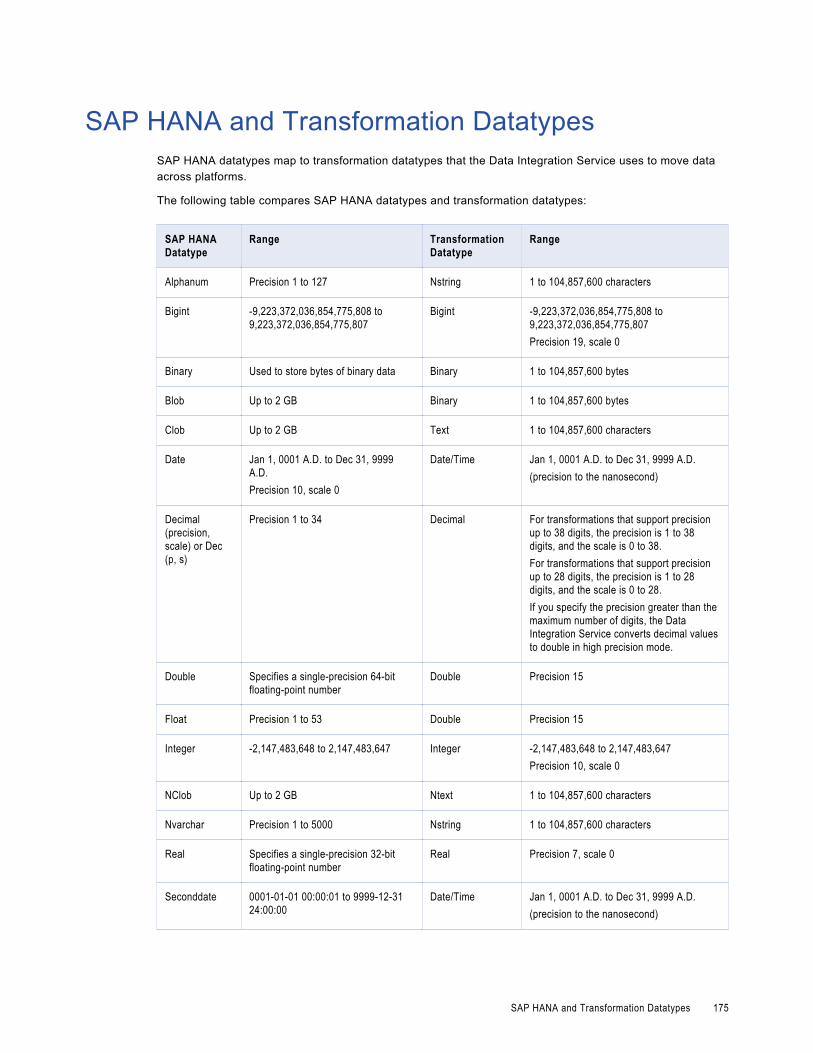
SAP HANA and Transformation DatatypesSAP HANA datatypes map to transformation datatypes that the Data Integration Service uses to move data across platforms.
The following table compares SAP HANA datatypes and transformation datatypes:
SAP HANA Datatype
Range Transformation Datatype
Range
Alphanum Precision 1 to 127 Nstring 1 to 104,857,600 characters
Bigint -9,223,372,036,854,775,808 to 9,223,372,036,854,775,807
Bigint -9,223,372,036,854,775,808 to 9,223,372,036,854,775,807Precision 19, scale 0
Binary Used to store bytes of binary data Binary 1 to 104,857,600 bytes
Blob Up to 2 GB Binary 1 to 104,857,600 bytes
Clob Up to 2 GB Text 1 to 104,857,600 characters
Date Jan 1, 0001 A.D. to Dec 31, 9999 A.D.Precision 10, scale 0
Date/Time Jan 1, 0001 A.D. to Dec 31, 9999 A.D.(precision to the nanosecond)
Decimal (precision, scale) or Dec (p, s)
Precision 1 to 34 Decimal For transformations that support precision up to 38 digits, the precision is 1 to 38 digits, and the scale is 0 to 38. For transformations that support precision up to 28 digits, the precision is 1 to 28 digits, and the scale is 0 to 28. If you specify the precision greater than the maximum number of digits, the Data Integration Service converts decimal values to double in high precision mode.
Double Specifies a single-precision 64-bit floating-point number
Double Precision 15
Float Precision 1 to 53 Double Precision 15
Integer -2,147,483,648 to 2,147,483,647 Integer -2,147,483,648 to 2,147,483,647Precision 10, scale 0
NClob Up to 2 GB Ntext 1 to 104,857,600 characters
Nvarchar Precision 1 to 5000 Nstring 1 to 104,857,600 characters
Real Specifies a single-precision 32-bit floating-point number
Real Precision 7, scale 0
Seconddate 0001-01-01 00:00:01 to 9999-12-31 24:00:00
Date/Time Jan 1, 0001 A.D. to Dec 31, 9999 A.D.(precision to the nanosecond)
SAP HANA and Transformation Datatypes 175
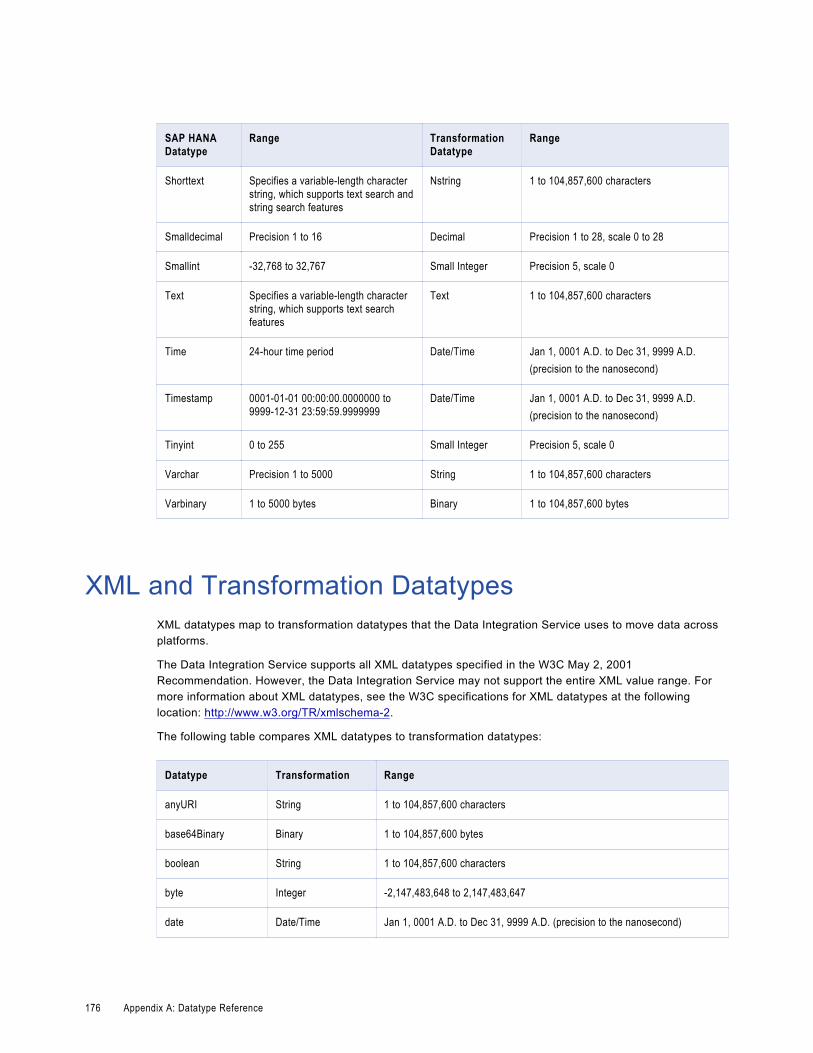
SAP HANA Datatype
Range Transformation Datatype
Range
Shorttext Specifies a variable-length character string, which supports text search and string search features
Nstring 1 to 104,857,600 characters
Smalldecimal Precision 1 to 16 Decimal Precision 1 to 28, scale 0 to 28
Smallint -32,768 to 32,767 Small Integer Precision 5, scale 0
Text Specifies a variable-length character string, which supports text search features
Text 1 to 104,857,600 characters
Time 24-hour time period Date/Time Jan 1, 0001 A.D. to Dec 31, 9999 A.D.(precision to the nanosecond)
Timestamp 0001-01-01 00:00:00.0000000 to 9999-12-31 23:59:59.9999999
Date/Time Jan 1, 0001 A.D. to Dec 31, 9999 A.D.(precision to the nanosecond)
Tinyint 0 to 255 Small Integer Precision 5, scale 0
Varchar Precision 1 to 5000 String 1 to 104,857,600 characters
Varbinary 1 to 5000 bytes Binary 1 to 104,857,600 bytes
XML and Transformation DatatypesXML datatypes map to transformation datatypes that the Data Integration Service uses to move data across platforms.
The Data Integration Service supports all XML datatypes specified in the W3C May 2, 2001 Recommendation. However, the Data Integration Service may not support the entire XML value range. For more information about XML datatypes, see the W3C specifications for XML datatypes at the following location: http://www.w3.org/TR/xmlschema-2.
The following table compares XML datatypes to transformation datatypes:
Datatype Transformation Range
anyURI String 1 to 104,857,600 characters
base64Binary Binary 1 to 104,857,600 bytes
boolean String 1 to 104,857,600 characters
byte Integer -2,147,483,648 to 2,147,483,647
date Date/Time Jan 1, 0001 A.D. to Dec 31, 9999 A.D. (precision to the nanosecond)
176 Appendix A: Datatype Reference

Datatype Transformation Range
dateTime Date/Time Jan 1, 0001 A.D. to Dec 31, 9999 A.D. (precision to the nanosecond)
decimal Decimal Precision 1 to 28, scale 0 to 28
double Double Precision of 15 digits
duration String 1 to 104,857,600 characters
ENTITIES String 1 to 104,857,600 characters
ENTITY String 1 to 104,857,600 characters
float Double Precision of 15 digits
gDay String 1 to 104,857,600 characters
gMonth String 1 to 104,857,600 characters
gMonthDay String 1 to 104,857,600 characters
gYear String 1 to 104,857,600 characters
gYearMonth String 1 to 104,857,600 characters
hexBinary Binary 1 to 104,857,600 bytes
ID String 1 to 104,857,600 characters
IDREF String 1 to 104,857,600 characters
IDREFS String 1 to 104,857,600 characters
int Integer -2,147,483,648 to 2,147,483,647
integer Integer -2,147,483,648 to 2,147,483,647
language String 1 to 104,857,600 characters
long Bigint -9,223,372,036,854,775,808 to 9,223,372,036,854,775,807
Name String 1 to 104,857,600 characters
NCName String 1 to 104,857,600 characters
negativeInteger Integer -2,147,483,648 to 2,147,483,647
NMTOKEN String 1 to 104,857,600 characters
NMTOKENS String 1 to 104,857,600 characters
nonNegativeInteger Integer -2,147,483,648 to 2,147,483,647
nonPositiveInteger Integer -2,147,483,648 to 2,147,483,647
XML and Transformation Datatypes 177

Datatype Transformation Range
normalizedString String 1 to 104,857,600 characters
NOTATION String 1 to 104,857,600 characters
positiveInteger Integer -2,147,483,648 to 2,147,483,647
QName String 1 to 104,857,600 characters
short Integer -2,147,483,648 to 2,147,483,647
string String 1 to 104,857,600 characters
time Date/Time Jan 1, 0001 A.D. to Dec 31, 9999 A.D. (precision to the nanosecond)
token String 1 to 104,857,600 characters
unsignedByte Integer -2,147,483,648 to 2,147,483,647
unsignedInt Integer -2,147,483,648 to 2,147,483,647
unsignedLong Bigint -9,223,372,036,854,775,808 to 9,223,372,036,854,775,807
unsignedShort Integer -2,147,483,648 to 2,147,483,647
Converting DataYou can convert data from one data type to another.
To convert data from one data type to another, use one the following methods:
• Pass data between ports (port-to-port data conversion).
• Use transformation functions to convert data.
• Use transformation arithmetic operators to convert data.
Port-to-Port Data ConversionThe Data Integration Service converts data based on the data type of the port. Each time data passes through a port, the Data Integration Service identifies the data type assigned to the port and converts the data based on the supported data type if required.
Pass Data Between Ports of the Same Data TypeYou can create a mapping to pass data between ports of the same data type. When you pass data between ports of the same data type, the Data Integration Service passes data without changing the data or data type.
When you pass data between ports of the same numeric data type and the data is transferred between transformations, the Data Integration Service does not always convert the data to the precision and scale of the port that the data is passed to.
178 Appendix A: Datatype Reference

You can transfer Decimal data between ports of different precision, scale, and precision modes in the following ways:
Pass Decimal data in low-precision mode
If you pass data to a Decimal port in low-precision mode, the Data Integration Service converts all Decimal ports to Double with a precision of 15 and a scale of 0. For example, you pass a value from Decimal (14, 3) to Decimal (9, 5) in low-precision mode. The Data Integration Service stores the value internally and does not truncate the data in low-precision mode.
Pass Decimal data with reduced scale in high-precision mode
If you pass data to a Decimal port in high-precision mode and with reduced scale between the Decimal ports, scale truncation occurs. For example, you pass a value from Decimal (18, 5) to Decimal (18, 2). When you pass 18.01234, the Data Integration Service truncates the scale of the data and the output data is 18.01.
Pass Decimal data with reduced precision in high-precision mode
You can pass data to a Decimal port in high-precision mode with reduced precision. For example, you pass a value from Decimal (19, 5) to a Decimal (17, 2) in high-precision mode. When the output field contains a value that exceeds 17 digits, the Data Integration Service rejects the row.
Pass Data Between Ports of Different Data TypesWhen you pass data between ports of different data types, the Data Integration Service uses the conversion functions in the transformation language to convert the data from one data type to another.
For example, you connect a String port to an Integer port. When the Data Integration Service runs the mapping, it uses the TO_INTEGER function to convert the input data from a string to an integer data type.
When the Data Integration Service performs port-to-port conversions, the data that you pass must be valid for the conversion data type. Any value that the Data Integration Service cannot convert results in a transformation row error. For example, you connect a String port that contains the value "9,000,000,000,000,000,000.777" to a Bigint port. The Data Integration Service cannot convert the String to a Bigint value and returns an error.
The Data Integration Service performs port-to-port conversions between transformations and between the last transformation in a pipeline and a target.
The following table describes the port-to-port conversions that the Data Integration Service performs:
Data Type Bigint Integer Decimal Double String, Text
Date/Time
Binary Timestamp with Time Zone
Bigint No Yes Yes Yes Yes No No No
Integer Yes No Yes Yes Yes No No No
Decimal Yes Yes No Yes Yes No No No
Double Yes Yes Yes No Yes No No No
String, Text Yes Yes Yes Yes Yes Yes No Yes
Date/Time No No No No Yes Yes No No
Converting Data 179

Data Type Bigint Integer Decimal Double String, Text
Date/Time
Binary Timestamp with Time Zone
Binary No No No No No No Yes No
Timestamp with Time Zone
No No No No Yes No No Yes
180 Appendix A: Datatype Reference

A P P E N D I X B
Keyboard ShortcutsThis appendix includes the following topics:
• Keyboard Shortcuts for Objects, 181
• Keyboard Shortcuts for Ports, 182
• Keyboard Shortcuts for the Transformation Palette, 183
• Keyboard Shortcuts for the Workbench, 183
Keyboard Shortcuts for ObjectsYou can use keyboard shortcuts to work with objects that are in the editor.
When you select an object in the editor, you can change the appearance of the object and move the object. When an object is selected, a green border appears around the object. A dotted line also appears around a selected object indicating that the object is in focus. You can focus on an object while allowing other objects to be selected. Move the focus from a selected object to another object when you want to select multiple objects in the editor.
Note: The navigation order of objects in the editor is from top to bottom and left to right.
You can perform the following tasks with keyboard shortcuts:
Select an object.
When the editor is selected, press Tab. The object is also in focus. Press Tab again to select the next object.
Select the previous object.
Press Shift+Tab.
Find a particular object.
Press Ctrl+O.
Focus on the next object.
When an object is in focus, press Ctrl+Tab to move the focus to the next object. The previous object remains selected. Press Ctrl+Tab again to focus on the next object.
Select multiple objects individually.
When an object is in focus, press Ctrl+Tab to move the focus to the next object that you want to select. Then press Ctrl+Spacebar to select the focused object. Repeat these steps to select multiple objects individually.
181

Iconize selected objects.
Press Ctrl+I.
Restore selected objects.
Press Ctrl+R.
Resize selected objects.
Press and hold Ctrl+Shift, and then use the Up, Down, Left, and Right arrow keys.
Move selected objects.
Use the arrow keys to move one or more objects one pixel at a time in any direction.
Go from an object to the editor.
When one or multiple objects are selected or in focus, press Esc.
Keyboard Shortcuts for PortsYou can use keyboard shortcuts to work with ports.
When you select a port, you can edit the port and link the port to other ports. When a port is selected, the entire port appears green. A dotted line also appears around one port value of the selected port indicating that the port is in focus. You can focus on a port while allowing other ports to be selected. Move the focus from one port to another port when you want to select multiple ports individually.
You can perform the following tasks with keyboard shortcuts:
Select a port.
When an object is selected and in focus, press Ctrl+G. Use the Up and Down arrow keys to select a different port.
Select multiple ports.
Press Shift+Up or Shift+Down.
Select multiple ports individually.
Press and hold the Ctrl key, and then use the Up and Down arrow keys to focus on the port that you want to select. Then press Ctrl+Spacebar to select the port. Repeat these steps to select multiple ports individually.
Focus on and edit the next port value.
Press Tab.
Focus on and edit the previous port value.
Press Shift+Tab.
Go from a port to the object.
Press Esc.
Link ports in two objects.
Select the ports that you want to link in the first object, and then press Ctrl+L. The selected ports become highlighted. Navigate to the second object and select the ports that you want to link. Press Ctrl+L to link the ports.
182 Appendix B: Keyboard Shortcuts

End linking mode.
Press Ctrl+Alt+L to clear the ports that you selected in the first object.
Select a link.
Press Ctrl+G from the selected port to select the outgoing link from that port.
Select the next link.
Press Tab.
Select the previous link.
Press Shift+Tab.
Keyboard Shortcuts for the Transformation PaletteYou can use keyboard shortcuts to navigate the Transformation palette.
You can perform the following tasks with keyboard shortcuts:
Go from the editor to the Transformation palette.
When an editor is selected, press Ctrl+Shift+P.
Navigate the Transformation palette.
Press Tab, or use the Up and Down arrow keys.
Go from the Transformation palette to the editor.
Press Esc.
Keyboard Shortcuts for the WorkbenchYou can use keyboard shortcuts to navigate editors and views in the workbench.
When you select an editor, you can navigate within the editor. A green border appears around an editor when it is selected.
You can focus on editors and views. A blue border appears around an editor or view when it is in focus. A dotted line appears around the tab of a view that is in focus. When a view is in focus, you can select the view or you can focus on another view.
You can perform the following tasks with keyboard shortcuts:
Focus on a view.
When an editor is selected, press Shift+Tab. Then use the Left and Right arrow keys to focus on another view within the same editor. Alternatively, press Shift+Tab until another view in the workbench is in focus.
Select the first area in a view.
When a view is in focus in an editor, press Ctrl+Tab. Press Ctrl+Tab again to select the next area.
Select the previous area in a view.
Press Ctrl+Shift+Tab.
Keyboard Shortcuts for the Transformation Palette 183

In the mapping Properties view, select and read a description.
Press Ctrl+A.
Minimize an editor.
When a view is in focus, press Shift+Tab to select the Minimize control, and then press the spacebar.
Maximize an editor.
When a view is in focus, press Shift+Tab to select the Minimize control. Use the Right arrow key to select the Maximize control, and then press the spacebar.
Select an area of the workbench.
When an editor is selected, press Ctrl+Tab to select another area of the workbench, such as a view. Press Ctrl+Tab again to select the next area.
Select the previous area of the workbench.
Press Ctrl+Shift+Tab.
Jump to the error message in a dialog box.
Press Ctrl+M.
184 Appendix B: Keyboard Shortcuts

A P P E N D I X C
Connection PropertiesThis appendix includes the following topics:
• Connection Properties Overview, 186
• Adabas Connection Properties, 186
• DataSift Connection Properties, 188
• Facebook Connection Properties, 189
• Greenplum Connection Properties, 190
• HBase Connection Properties, 192
• HDFS Connection Properties, 193
• Hive Connection Properties, 193
• HTTP Connection Properties, 199
• IBM DB2 Connection Properties, 201
• IBM DB2 for i5/OS Connection Properties, 204
• IBM DB2 for z/OS Connection Properties, 207
• IMS Connection Properties, 210
• JDBC Connection Properties, 213
• JD Edwards EnterpriseOne Connection Properties, 216
• LDAP Connection Properties, 217
• LinkedIn Connection Properties, 218
• Microsoft Azure Blob Storage Connection Properties, 219
• Microsoft Azure SQL Data Warehouse Connection Properties, 220
• MS SQL Server Connection Properties, 221
• Netezza Connection Properties, 225
• OData Connection Properties, 226
• ODBC Connection Properties, 227
• Oracle Connection Properties, 228
• Salesforce Connection Properties, 231
• SAP Connection Properties, 232
• Sequential Connection Properties, 234
• Teradata Parallel Transporter Connection Properties, 236
• Twitter Connection Properties, 238
• Twitter Streaming Connection Properties, 239
185

• VSAM Connection Properties, 240
• Web Content-Kapow Katalyst Connection Properties, 242
• Web Services Connection Properties, 243
• Identifier Properties in Database Connections, 245
Connection Properties OverviewConnection properties enable the Informatica client to connect to data sources.
This chapter contains connection properties for each of the connections you can create and manage through Informatica clients.
Adabas Connection PropertiesUse an Adabas connection to access an Adabas database. The Adabas connection is a mainframe database type connection. You create an Adabas connection in the Developer tool. You can manage an Adabas connection in the Administrator tool or the Developer tool.
The following table describes Adabas connection properties:
Option Description
Location Node name for the location of the PowerExchange Listener that connects to Adabas. The node name is defined in the first parameter of the NODE statement in the PowerExchange dbmover.cfg configuration file.
User Name Database user name.For a database on a supported Linux or UNIX system, if you have enabled PowerExchange LDAP user authentication, the user name is the enterprise user name. For more information, see the PowerExchange Reference Manual.
186 Appendix C: Connection Properties

Option Description
Password Password for the database user name or a valid PowerExchange passphrase.A PowerExchange passphrase can be from 9 to 128 characters in length and can contain the following characters:- Uppercase and lowercase letters- The numbers 0 to 9- Spaces- The following special characters:’ - ; # \ , . / ! % & * ( ) _ + { } : @ | < > ? Note: The first character is an apostrophe.
Passphrases cannot include single quotation marks (‘), double quotation marks (“), or currency symbols.To use passphrases, ensure that the PowerExchange Listener runs with a security setting of SECURITY=(1,N) or higher in the DBMOVER member. For more information, see "SECURITY Statement" in the PowerExchange Reference Manual.The allowable characters in the IBM IRRPHREX exit do not affect the allowable characters in PowerExchange passphrases.Note: A valid RACF passphrase can be up to 100 characters in length. PowerExchange truncates passphrases longer than 100 characters when passing them to RACF for validation.
Code Page Required. Name of the code page to use for reading from or writing to the data source. Usually, this value is an ISO code page name, such as ISO-8859-6.
Pass-through security enabled
Enables pass-through security for the connection. When you enable pass-through security for a connection, the domain uses the client user name and password to log into the corresponding database, instead of the credentials defined in the connection object.
Encryption Type The type of encryption that the Data Integration Service uses. Select one of the following options:- None- RC2- DESDefault is None.Notes: - Informatica recommends that you use Secure Sockets Layer (SSL) authentication instead of
configuring the Encryption Type and Level connection properties or the ENCRYPT and ENCRYPTLEVEL statements in the DBMOVER configuration file. SSL authentication provides stricter security and is used by several Informatica products.For more information about implementing SSL authentication in a PowerExchange network, see the PowerExchange Reference Manual.
- The values that you select for the Encryption Type and Level connection attributes override the values in the ENCRYPT and ENCRYPTLEVEL statements, if defined, in the DBMOVER configuration file on the Integration Service machine. To enable encryption for a mapping, be sure to select the appropriate connection attributes.
[Encryption] Level If you selected RC2 or DES for Encryption Type, select one of the following options to indicate the encryption level that the Data Integration Service uses:- 1. Use a 56-bit encryption key for DES and RC2.- 2. Use 168-bit triple encryption key for DES, and use a 64-bit encryption key for RC2.- 3. Use 168-bit triple encryption key for DES, and use a 128-bit encryption key for RC2.This option is ignored if you do not select an encryption type.Default is 1.
Adabas Connection Properties 187

Option Description
Pacing size Optional. Amount of data that the source system can pass to the PowerExchange Listener. Set the pacing size if an external application, database, or the Data Integration Service node is a bottleneck. User lower values for faster performance.The minimum value and default value is 0. A value of 0 provides the best performance.
Interpret as rows Optional. Select this option to express the pacing size as a number of rows. Clear this option to express the pacing size in kilobytes. By default, this option is not selected and the pacing size is in kilobytes.
Compression Optional. Select this option to enable source data compression. By compressing data, you can decrease the amount of data that Informatica applications send over the network. By default, this option is not selected and compression is disabled.
Offload processing Optional. Controls whether to offload some bulk data processing from the source machine to the Data Integration Service machine. Select one of the following options:- AUTO. The Data Integration Service determines whether to use offload processing.- Yes. Use offload processing.- No. Do not use offload processing.Default is AUTO.
Worker threads Optional. Number of threads that the Data Integration Service uses to process bulk data when offload processing is enabled. For optimal performance, this value should not exceed the number of available processors on the Data Integration Service machine. Valid values are 1 through 64. Default is 0, which disables multithreading.
Array size Optional. The number of records in the storage array for the worker threads. This option is applicable when you set the Worker Threads option to a value greater than 0. Valid values are 1 to 100000. Default is 25.
Write mode Optional. Mode in which Data Integration Service sends data to the PowerExchange Listener. Select one of the following write modes:- CONFIRMWRITEON. Sends data to the PowerExchange Listener and waits for a response before
sending more data. Select this option when error recovery is a priority. However, this option might degrade performance.
- CONFIRMWRITEOFF. Sends data to the PowerExchange Listener without waiting for a response. Use this option if you can reload the target table when an error occurs.
- ASYNCHRONOUSWITHFAULTTOLERANCE. Sends data to the PowerExchange Listener without waiting for a response. This option also enables error detection. This option combines the speed of CONFIRMWRITEOFF and the data integrity of CONFIRMWRITEON.
Default is CONFIRMWRITEON.
DataSift Connection PropertiesUse a DataSift connection to extract data from the DataSift streams. A DataSift connection is a social media connection. You can create and manage a DataSift connection in the Administrator tool or the Developer tool.
Note: The order of the connection properties might vary depending on the tool where you view them.
188 Appendix C: Connection Properties

The following table describes DataSift connection properties:
Property Description
Name Name of the connection. The name is not case sensitive and must be unique within the domain. The name cannot exceed 128 characters, contain spaces, or contain the following special characters:~ ` ! $ % ^ & * ( ) - + = { [ } ] | \ : ; " ' < , > . ? /
ID String that the Data Integration Service uses to identify the connection. The ID is not case sensitive. It must be 255 characters or less and must be unique in the domain. You cannot change this property after you create the connection. Default value is the connection name.
Description The description of the connection. The description cannot exceed 765 characters.
Location The domain where you want to create the connection.
Type The connection type. Select DataSift.
Username User name for the DataSift account.
API Key API key. The Developer API key that appears in the Dashboard or Settings page in the DataSift account.
Facebook Connection PropertiesUse a Facebook connection to access data from the Facebook web site. A Facebook connection is a social media connection. You can create and manage a Facebook connection in the Administrator tool or the Developer tool.
Note: The order of the connection properties might vary depending on the tool where you view them.
The following table describes Facebook connection properties:
Property Description
Name Name of the connection. The name is not case sensitive and must be unique within the domain. The name cannot exceed 128 characters, contain spaces, or contain the following special characters:~ ` ! $ % ^ & * ( ) - + = { [ } ] | \ : ; " ' < , > . ? /
ID String that the Data Integration Service uses to identify the connection. The ID is not case sensitive. It must be 255 characters or less and must be unique in the domain. You cannot change this property after you create the connection. Default value is the connection name.
Description The description of the connection. The description cannot exceed 765 characters.
Location The domain where you want to create the connection.
Type The connection type. Select Facebook.
Do you have OAuth details?
Indicates whether you want to configure OAuth. Select one of the following values:- Yes. Indicates that you have the access token.- No. Launches the OAuth Utility.
Facebook Connection Properties 189

Property Description
Consumer Key The App ID that you get when you create the application in Facebook. Facebook uses the key to identify the application.
Consumer Secret The App Secret that you get when you create the application in Facebook. Facebook uses the secret to establish ownership of the consumer key.
Access Token Access token that the OAuth Utility returns. Facebook uses this token instead of the user credentials to access the protected resources.
Access Secret Access secret is not required for Facebook connection.
Scope Permissions for the application. Enter the permissions you used to configure OAuth.
Greenplum Connection PropertiesUse a Greenplum connection to connect to a Greenplum database. The Greenplum connection is a relational type connection. You can create and manage a Greenplum connection in the Administrator tool or the Developer tool.
Note: The order of the connection properties might vary depending on the tool where you view them.
When you create a Greenplum connection, you enter information for metadata and data access.
The following table describes Greenplum connection properties:
Property Description
Name Name of the Greenplum relational connection.
ID String that the Data Integration Service uses to identify the connection. The ID is not case sensitive. It must be 255 characters or fewer and must be unique in the domain. You cannot change this property after you create the connection. Default value is the connection name.
Description Description of the connection. The description cannot exceed 765 characters.
Location Domain on which you want to create the connection.
Type Type of connection.
The user name, password, driver name, and connection string are required to import the metadata. The following table describes the properties for metadata access:
Property Description
User Name User name with permissions to access the Greenplum database.
Password Password to connect to the Greenplum database.
190 Appendix C: Connection Properties

Property Description
Driver Name The name of the Greenplum JDBC driver.For example: com.pivotal.jdbc.GreenplumDriverFor more information about the driver, see the Greenplum documentation.
Connection String Use the following connection URL:jdbc:pivotal:greenplum://<hostname>:<port>;DatabaseName=<database_name>For more information about the connection URL, see the Greenplum documentation.
PowerExchange for Greenplum uses the host name, port number, and database name to create a control file to provide load specifications to the Greenplum gpload bulk loading utility. It uses the Enable SSL option and the certificate path to establish secure communication to the Greenplum server over SSL.
The following table describes the connection properties for data access:
Property Description
Host Name Host name or IP address of the Greenplum server.
Port Number Greenplum server port number. If you enter 0, the gpload utility reads from the environment variable $PGPORT. Default is 5432.
Database Name Name of the database.
Enable SSL Select this option to establish secure communication between the gpload utility and the Greenplum server over SSL.
Certificate Path Path where the SSL certificates for the Greenplum server are stored.For information about the files that need to be present in the certificates path, see the gpload documentation.
Greenplum Connection Properties 191

HBase Connection PropertiesUse an HBase connection to access HBase. The HBase connection is a NoSQL connection. You can create and manage an HBase connection in the Administrator tool or the Developer tool. Hbase connection properties are case sensitive unless otherwise noted.
The following table describes HBase connection properties:
Property Description
Name The name of the connection. The name is not case sensitive and must be unique within the domain. You can change this property after you create the connection. The name cannot exceed 128 characters, contain spaces, or contain the following special characters:~ ` ! $ % ^ & * ( ) - + = { [ } ] | \ : ; " ' < , > . ? /
ID String that the Data Integration Service uses to identify the connection. The ID is not case sensitive. It must be 255 characters or less and must be unique in the domain. You cannot change this property after you create the connection. Default value is the connection name.
Description The description of the connection. The description cannot exceed 4,000 characters.
Location The domain where you want to create the connection.
Type The connection type. Select HBase.
ZooKeeper Host(s) Name of the machine that hosts the ZooKeeper server. The name is case sensitive.When the ZooKeeper runs in the replicated mode, specify a comma-separated list of servers in the ZooKeeper quorum servers. If the TCP connection to the server breaks, the client connects to a different server in the quorum.
ZooKeeper Port Port number of the machine that hosts the ZooKeeper server.
Enable Kerberos Connection Enables the Informatica domain to communicate with the HBase master server or region server that uses Kerberos authentication.
HBase Master Principal Service Principal Name (SPN) of the HBase master server. Enables the ZooKeeper server to communicate with an HBase master server that uses Kerberos authentication.Enter a string in the following format:
hbase/<domain.name>@<YOUR-REALM>Where:- domain.name is the domain name of the machine that hosts the HBase master server.- YOUR-REALM is the Kerberos realm.
HBase Region Server Principal Service Principal Name (SPN) of the HBase region server. Enables the ZooKeeper server to communicate with an HBase region server that uses Kerberos authentication.Enter a string in the following format:
hbase_rs/<domain.name>@<YOUR-REALM>Where:- domain.name is the domain name of the machine that hosts the HBase master server.- YOUR-REALM is the Kerberos realm.
192 Appendix C: Connection Properties

HDFS Connection PropertiesUse a Hadoop File System (HDFS) connection to access data in the Hadoop cluster. The HDFS connection is a file system type connection. You can create and manage an HDFS connection in the Administrator tool, Analyst tool, or the Developer tool. HDFS connection properties are case sensitive unless otherwise noted.
Note: The order of the connection properties might vary depending on the tool where you view them.
The following table describes HDFS connection properties:
Property Description
Name Name of the connection. The name is not case sensitive and must be unique within the domain. The name cannot exceed 128 characters, contain spaces, or contain the following special characters:~ ` ! $ % ^ & * ( ) - + = { [ } ] | \ : ; " ' < , > . ? /
ID String that the Data Integration Service uses to identify the connection. The ID is not case sensitive. It must be 255 characters or less and must be unique in the domain. You cannot change this property after you create the connection. Default value is the connection name.
Description The description of the connection. The description cannot exceed 765 characters.
Location The domain where you want to create the connection. Not valid for the Analyst tool.
Type The connection type. Default is Hadoop File System.
User Name User name to access HDFS.
NameNode URI
The URI to access HDFS.Use the following format to specify the NameNode URI in Cloudera and Hortonworks distributions:hdfs://<namenode>:<port>Where- <namenode> is the host name or IP address of the NameNode.- <port> is the port that the NameNode listens for remote procedure calls (RPC).Use one of the following formats to specify the NameNode URI in MapR distribution:- maprfs:///- maprfs:///mapr/my.cluster.com/Where my.cluster.com is the cluster name that you specify in the mapr-clusters.conf file.
Hive Connection PropertiesUse the Hive connection to access Hive data. A Hive connection is a database type connection. You can create and manage a Hive connection in the Administrator tool, Analyst tool, or the Developer tool. Hive connection properties are case sensitive unless otherwise noted.
Note: The order of the connection properties might vary depending on the tool where you view them.
HDFS Connection Properties 193

The following table describes Hive connection properties:
Property Description
Name The name of the connection. The name is not case sensitive and must be unique within the domain. You can change this property after you create the connection. The name cannot exceed 128 characters, contain spaces, or contain the following special characters:~ ` ! $ % ^ & * ( ) - + = { [ } ] | \ : ; " ' < , > . ? /
ID String that the Data Integration Service uses to identify the connection. The ID is not case sensitive. It must be 255 characters or less and must be unique in the domain. You cannot change this property after you create the connection. Default value is the connection name.
Description The description of the connection. The description cannot exceed 4000 characters.
Location The domain where you want to create the connection. Not valid for the Analyst tool.
Type The connection type. Select Hive.
Connection Modes Hive connection mode. Select at least one of the following options:- Access HiveServer2 to run mappings. Select this option if you want to use Hive as a
source or a target. You can enable the same connection or another Hive connection to run mappings in HiveServer2 in the Hadoop cluster.
- Access Hive CLI to run mappings. Select this option if you want to use the Hive CLI to run mappings in the Hadoop cluster.
You can select both the options. If you select both the options, the connection created can be used for Hive as a source or target or to run the mapping in the Pushdown mode.
194 Appendix C: Connection Properties

Property Description
User Name User name of the user that the Data Integration Service impersonates to run mappings on a Hadoop cluster. The user name depends on the JDBC connection string that you specify in the Metadata Connection String or Data Access Connection String for the native environment.If the Hadoop cluster runs Hortonworks HDP, you must provide a user name. If you use Tez to run mappings, you must provide the user account for the Data Integration Service. If you do not use Tez to run mappings, you can use an impersonation user account.If the Hadoop cluster uses Kerberos authentication, the principal name for the JDBC connection string and the user name must be the same. Otherwise, the user name depends on the behavior of the JDBC driver. With Hive JDBC driver, you can specify a user name in many ways and the user name can become a part of the JDBC URL.If the Hadoop cluster does not use Kerberos authentication, the user name depends on the behavior of the JDBC driver.If you do not specify a user name, the Hadoop cluster authenticates jobs based on the following criteria:- The Hadoop cluster does not use Kerberos authentication. It authenticates jobs based
on the operating system profile user name of the machine that runs the Data Integration Service.
- The Hadoop cluster uses Kerberos authentication. It authenticates jobs based on the SPN of the Data Integration Service.
Common Attributes to Both the Modes: Environment SQL
SQL commands to set the Hadoop environment. In native environment type, the Data Integration Service executes the environment SQL each time it creates a connection to a Hive metastore. If you use the Hive connection to run profiles in the Hadoop cluster, the Data Integration Service executes the environment SQL at the beginning of each Hive session.The following rules and guidelines apply to the usage of environment SQL in both connection modes:- Use the environment SQL to specify Hive queries.- Use the environment SQL to set the classpath for Hive user-defined functions and
then use environment SQL or PreSQL to specify the Hive user-defined functions. You cannot use PreSQL in the data object properties to specify the classpath. The path must be the fully qualified path to the JAR files used for user-defined functions. Set the parameter hive.aux.jars.path with all the entries in infapdo.aux.jars.path and the path to the JAR files for user-defined functions.
- You can use environment SQL to define Hadoop or Hive parameters that you want to use in the PreSQL commands or in custom queries.
- If you use multiple values for the Environment SQL property, ensure that there is no space between the values. The following sample text shows two values that can be used for the Environment SQL:set hive.execution.engine='tez';set hive.exec.dynamic.partition.mode='nonstrict';
If you use the Hive connection to run profiles in the Hadoop cluster, the Data Integration service executes only the environment SQL of the Hive connection. If the Hive sources and targets are on different clusters, the Data Integration Service does not execute the different environment SQL commands for the connections of the Hive source or target.
Hive Connection Properties 195

Properties to Access Hive as Source or TargetThe following table describes the connection properties that you configure to access Hive as a source or target:
Property Description
Metadata Connection String
The JDBC connection URI used to access the metadata from the Hadoop server.You can use PowerExchange for Hive to communicate with a HiveServer service or HiveServer2 service.To connect to HiveServer, specify the connection string in the following format:jdbc:hive2://<hostname>:<port>/<db>Where- <hostname> is name or IP address of the machine on which HiveServer2 runs.- <port> is the port number on which HiveServer2 listens.- <db> is the database name to which you want to connect. If you do not provide the database name, the
Data Integration Service uses the default database details.To connect to HiveServer 2, use the connection string format that Apache Hive implements for that specific Hadoop Distribution. For more information about Apache Hive connection string formats, see the Apache Hive documentation.
Bypass Hive JDBC Server
JDBC driver mode. Select the check box to use the embedded JDBC driver mode.To use the JDBC embedded mode, perform the following tasks:- Verify that Hive client and Informatica services are installed on the same machine.- Configure the Hive connection properties to run mappings in the Hadoop cluster.If you choose the non-embedded mode, you must configure the Data Access Connection String.Informatica recommends that you use the JDBC embedded mode.
Data Access Connection String
The connection string to access data from the Hadoop data store.To connect to HiveServer, specify the non-embedded JDBC mode connection string in the following format:jdbc:hive2://<hostname>:<port>/<db>Where- <hostname> is name or IP address of the machine on which HiveServer2 runs.- <port> is the port number on which HiveServer2 listens.- <db> is the database to which you want to connect. If you do not provide the database name, the Data
Integration Service uses the default database details.To connect to HiveServer 2, use the connection string format that Apache Hive implements for the specific Hadoop Distribution. For more information about Apache Hive connection string formats, see the Apache Hive documentation.
196 Appendix C: Connection Properties

Properties to Run Mappings in Hadoop ClusterThe following table describes the Hive connection properties that you configure when you want to use the Hive connection to run Informatica mappings in the Hadoop cluster:
Property Description
Database Name Namespace for tables. Use the name default for tables that do not have a specified database name.
Default FS URI The URI to access the default Hadoop Distributed File System.Use the following connection URI:hdfs://<node name>:<port>Where- <node name> is the host name or IP address of the NameNode.- <port> is the port on which the NameNode listens for remote procedure calls (RPC).If the Hadoop cluster runs MapR, use the following URI to access the MapR File system: maprfs:///.
JobTracker/Yarn Resource Manager URI
The service within Hadoop that submits the MapReduce tasks to specific nodes in the cluster.Use the following format:<hostname>:<port>Where- <hostname> is the host name or IP address of the JobTracker or Yarn resource
manager.- <port> is the port on which the JobTracker or Yarn resource manager listens for
remote procedure calls (RPC).If the cluster uses MapR with YARN, use the value specified in the yarn.resourcemanager.address property in yarn-site.xml. You can find yarn-site.xml in the following directory on the NameNode of the cluster: /opt/mapr/hadoop/hadoop-2.5.1/etc/hadoop.MapR with MapReduce 1 supports a highly available JobTracker. If you are using MapR distribution, define the JobTracker URI in the following format: maprfs:///
Hive Warehouse Directory on HDFS
The absolute HDFS file path of the default database for the warehouse that is local to the cluster. For example, the following file path specifies a local warehouse:/user/hive/warehouseFor Cloudera CDH, if the Metastore Execution Mode is remote, then the file path must match the file path specified by the Hive Metastore Service on the Hadoop cluster.For MapR, use the value specified for the hive.metastore.warehouse.dir property in hive-site.xml. You can find hive-site.xml in the following directory on the node that runs HiveServer2: /opt/mapr/hive/hive-0.13/conf.
Hive Connection Properties 197

Property Description
Advanced Hive/Hadoop Properties Configures or overrides Hive or Hadoop cluster properties in hive-site.xml on the machine on which the Data Integration Service runs. You can specify multiple properties.Select Edit to specify the name and value for the property. The property appears in the following format:<property1>=<value>Where- <property1> is a Hive or Hadoop property in hive-site.xml.- <value> is the value of the Hive or Hadoop property.When you specify multiple properties, &: appears as the property separator.The maximum length for the format is 1 MB.If you enter a required property for a Hive connection, it overrides the property that you configure in the Advanced Hive/Hadoop Properties.The Data Integration Service adds or sets these properties for each map-reduce job. You can verify these properties in the JobConf of each mapper and reducer job. Access the JobConf of each job from the Jobtracker URL under each map-reduce job.The Data Integration Service writes messages for these properties to the Data Integration Service logs. The Data Integration Service must have the log tracing level set to log each row or have the log tracing level set to verbose initialization tracing.For example, specify the following properties to control and limit the number of reducers to run a mapping job:mapred.reduce.tasks=2&:hive.exec.reducers.max=10
Temporary Table Compression Codec
Hadoop compression library for a compression codec class name.
Codec Class Name Codec class name that enables data compression and improves performance on temporary staging tables.
Metastore Execution Mode Controls whether to connect to a remote metastore or a local metastore. By default, local is selected. For a local metastore, you must specify the Metastore Database URI, Driver, Username, and Password. For a remote metastore, you must specify only the Remote Metastore URI.
Metastore Database URI The JDBC connection URI used to access the data store in a local metastore setup. Use the following connection URI:jdbc:<datastore type>://<node name>:<port>/<database name>where- <node name> is the host name or IP address of the data store.- <data store type> is the type of the data store.- <port> is the port on which the data store listens for remote procedure calls (RPC).- <database name> is the name of the database.For example, the following URI specifies a local metastore that uses MySQL as a data store:jdbc:mysql://hostname23:3306/metastoreFor MapR, use the value specified for the javax.jdo.option.ConnectionURL property in hive-site.xml. You can find hive-site.xml in the following directory on the node where HiveServer 2 runs: /opt/mapr/hive/hive-0.13/conf.
198 Appendix C: Connection Properties

Property Description
Metastore Database Driver Driver class name for the JDBC data store. For example, the following class name specifies a MySQL driver:com.mysql.jdbc.DriverFor MapR, use the value specified for the javax.jdo.option.ConnectionDriverName property in hive-site.xml. You can find hive-site.xml in the following directory on the node where HiveServer 2 runs: /opt/mapr/hive/hive-0.13/conf.
Metastore Database Username The metastore database user name.For MapR, use the value specified for the javax.jdo.option.ConnectionUserName property in hive-site.xml. You can find hive-site.xml in the following directory on the node where HiveServer 2 runs: /opt/mapr/hive/hive-0.13/conf.
Metastore Database Password The password for the metastore user name.For MapR, use the value specified for the javax.jdo.option.ConnectionPassword property in hive-site.xml. You can find hive-site.xml in the following directory on the node where HiveServer 2 runs: /opt/mapr/hive/hive-0.13/conf.
Remote Metastore URI The metastore URI used to access metadata in a remote metastore setup. For a remote metastore, you must specify the Thrift server details.Use the following connection URI:thrift://<hostname>:<port>Where- <hostname> is name or IP address of the Thrift metastore server.- <port> is the port on which the Thrift server is listening.For MapR, use the value specified for the hive.metastore.uris property in hive-site.xml. You can find hive-site.xml in the following directory on the node where HiveServer 2 runs: /opt/mapr/hive/hive-0.13/conf.
HTTP Connection PropertiesUse an HTTP connection to connect a REST Web Service Consumer transformation to a web service. The HTTP connection is a web type connection. You create an HTTP connection in the Developer tool. You can manage an HTTP connection in the Administrator tool or the Developer tool.
Note: The order of the connection properties might vary depending on the tool where you view them.
HTTP Connection Properties 199

The following table describes HTTP connection properties:
Property Description
Name Name of the connection. The name is not case sensitive and must be unique within the domain. The name cannot exceed 128 characters, contain spaces, or contain the following special characters:~ ` ! $ % ^ & * ( ) - + = { [ } ] | \ : ; " ' < , > . ? /
ID String that the Data Integration Service uses to identify the connection. The ID is not case sensitive. It must be 255 characters or less and must be unique in the domain. You cannot change this property after you create the connection. Default value is the connection name.
Username User name to connect to the web service. Enter a user name if you enable HTTP authentication or WS-Security.If the Web Service Consumer transformation includes WS-Security ports, the transformation receives a dynamic user name through an input port. The Data Integration Service overrides the user name defined in the connection.
Password Password for the user name. Enter a password if you enable HTTP authentication or WS-Security.If the Web Service Consumer transformation includes WS-Security ports, the transformation receives a dynamic password through an input port. The Data Integration Service overrides the password defined in the connection.
End Point URL URL for the web service that you want to access. The Data Integration Service overrides the URL defined in the WSDL file.If the Web Service Consumer transformation includes an endpoint URL port, the transformation dynamically receives the URL through an input port. The Data Integration Service overrides the URL defined in the connection.
Timeout Number of seconds that the Data Integration Service waits for a response from the web service provider before it closes the connection.
HTTP Authentication Type
Type of user authentication over HTTP. Select one of the following values:- None. No authentication.- Automatic. The Data Integration Service chooses the authentication type of the web service provider.- Basic. Requires you to provide a user name and password for the domain of the web service provider.
The Data Integration Service sends the user name and the password to the web service provider for authentication.
- Digest. Requires you to provide a user name and password for the domain of the web service provider. The Data Integration Service generates an encrypted message digest from the user name and password and sends it to the web service provider. The provider generates a temporary value for the user name and password and stores it in the Active Directory on the Domain Controller. It compares the value with the message digest. If they match, the web service provider authenticates you.
- NTLM. Requires you to provide a domain name, server name, or default user name and password. The web service provider authenticates you based on the domain you are connected to. It gets the user name and password from the Windows Domain Controller and compares it with the user name and password that you provide. If they match, the web service provider authenticates you. NTLM authentication does not store encrypted passwords in the Active Directory on the Domain Controller.
Trust Certificates File
File containing the bundle of trusted certificates that the Data Integration Service uses when authenticating the SSL certificate of the web service. Enter the file name and full directory path.Default is <Informatica installation directory>/services/shared/bin/ca-bundle.crt.
Client Certificate File Name
Client certificate that a web service uses when authenticating a client. Specify the client certificate file if the web service needs to authenticate the Data Integration Service.
200 Appendix C: Connection Properties

Property Description
Client Certificate Password
Password for the client certificate. Specify the client certificate password if the web service needs to authenticate the Data Integration Service.
Client Certificate Type
Format of the client certificate file. Select one of the following values:- PEM. Files with the .pem extension.- DER. Files with the .cer or .der extension.Specify the client certificate type if the web service needs to authenticate the Data Integration Service.
Private Key File Name
Private key file for the client certificate. Specify the private key file if the web service needs to authenticate the Data Integration Service.
Private Key Password
Password for the private key of the client certificate. Specify the private key password if the web service needs to authenticate the Data Integration Service.
Private Key Type Type of the private key. PEM is the supported type.
IBM DB2 Connection PropertiesUse an IBM DB2 connection to access IBM DB2. An IBM DB2 connection is a relational database connection. You can create and manage an IBM DB2 connection in the Administrator tool, the Developer tool, or the Analyst tool.
Note: The order of the connection properties might vary depending on the tool where you view them.
The following table describes DB2 connection properties:
Property Description
Database Type The database type.
Name Name of the connection. The name is not case sensitive and must be unique within the domain. The name cannot exceed 128 characters, contain spaces, or contain the following special characters:~ ` ! $ % ^ & * ( ) - + = { [ } ] | \ : ; " ' < , > . ? /
ID String that the Data Integration Service uses to identify the connection. The ID is not case sensitive. It must be 255 characters or less and must be unique in the domain. You cannot change this property after you create the connection. Default value is the connection name.
Description The description of the connection. The description cannot exceed 765 characters.
User Name The database user name.
Password The password for the database user name.
Pass-through security enabled Enables pass-through security for the connection. When you enable pass-through security for a connection, the domain uses the client user name and password to log into the corresponding database, instead of the credentials defined in the connection object.
IBM DB2 Connection Properties 201

Property Description
Connection String for data access
The DB2 connection URL used to access metadata from the database.dbnameWhere dbname is the alias configured in the DB2 client.
Metadata Access Properties: Connection String
Use the following metadata connection string URL:jdbc:informatica:db2://<host name>:<port>;DatabaseName=<database name>When you import a table, by default, all tables are displayed under the default schema name. To view tables under a specific schema instead of the default schema, you can specify the schema name from which you want to import the table. Include the ischemaname parameter in the URL to specify the schema name. For example, use the following syntax to import a table from a specific schema:jdbc:informatica:db2://<host name>:<port>;DatabaseName=<database name>;ischemaname=<schema_name>To search for a table in multiple schemas and import it, you can specify multiple schema names in the ischemaname parameter. The schema name is case sensitive. You cannot use special characters when you specify multiple schema names. Use the pipe (|) character to separate multiple schema names. For example, use the following syntax to search for a table in three schemas and import it:jdbc:informatica:db2://<host name>:<port>;DatabaseName=<database name>;ischemaname=<schema_name1>|<schema_name2>|<schema_name3>When you specify multiple schema names, you must clear the Show Default Schema Only option to view the tables under the specified schema names.
202 Appendix C: Connection Properties

Property Description
AdvancedJDBCSecurityOptions
Database parameters for metadata access to a secure database. Informatica treats the value of the AdvancedJDBCSecurityOptions field as sensitive data and stores the parameter string encrypted.To connect to a secure database, include the following parameters:- EncryptionMethod. Required. Indicates whether data is encrypted when transmitted over
the network. This parameter must be set to SSL.- ValidateServerCertificate. Optional. Indicates whether Informatica validates the certificate
that is sent by the database server.If this parameter is set to True, Informatica validates the certificate that is sent by the database server. If you specify the HostNameInCertificate parameter, Informatica also validates the host name in the certificate.If this parameter is set to false, Informatica does not validate the certificate that is sent by the database server. Informatica ignores any truststore information that you specify.
- HostNameInCertificate. Optional. Host name of the machine that hosts the secure database. If you specify a host name, Informatica validates the host name included in the connection string against the host name in the SSL certificate.
- cryptoProtocolVersion. Optional. If you enable TLS for the IBM DB2 instance, set the cryptoProtocolVersion parameter as follows:cryptoProtocolVersion=TLSv<version number>.For example, cryptoProtocolVersion=TLSv1.2Note: The version number must be the same as the TLS version you configured for the server.
- TrustStore. Required. Path and file name of the truststore file.Note: If you configure SSL or TLS and specify only the file name, you must copy the truststore file to the Informatica installation directory. To test the connection and import metadata, copy the truststore file to the following directory: <Informatica client installation directory>/clients/DeveloperClientTo run the mapping, copy the truststore file to the following directory:<Informatica server installation directory>/tomcat/bin
- TrustStorePassword. Required. Password for the truststore file for the secure database.Note: Informatica appends the secure JDBC parameters to the connection string. If you include the secure JDBC parameters directly to the connection string, do not enter any parameters in the AdvancedJDBCSecurityOptions field.
Data Access Properties: Connection String
The connection string used to access data from the database.For IBM DB2 this is <database name>
Code Page The code page used to read from a source database or to write to a target database or file.
Environment SQL SQL commands to set the database environment when you connect to the database. The Data Integration Service runs the connection environment SQL each time it connects to the database.
Transaction SQL SQL commands to set the database environment when you connect to the database. The Data Integration Service runs the transaction environment SQL at the beginning of each transaction.
Retry Period This property is reserved for future use.
Tablespace The tablespace name of the database.
IBM DB2 Connection Properties 203

Property Description
SQL Identifier Character Type of character that the database uses to enclose delimited identifiers in SQL queries. The available characters depend on the database type.Select (None) if the database uses regular identifiers. When the Data Integration Service generates SQL queries, the service does not place delimited characters around any identifiers.Select a character if the database uses delimited identifiers. When the Data Integration Service generates SQL queries, the service encloses delimited identifiers within this character.
Support Mixed-case Identifiers
Enable if the database uses case-sensitive identifiers. When enabled, the Data Integration Service encloses all identifiers within the character selected for the SQL Identifier Character property.When the SQL Identifier Character property is set to none, the Support Mixed-case Identifiers property is disabled.
ODBC Provider ODBC. The type of database to which ODBC connects. For pushdown optimization, specify the database type to enable the Data Integration Service to generate native database SQL. The options are:- Other- Sybase- Microsoft_SQL_ServerDefault is Other.
IBM DB2 for i5/OS Connection PropertiesUse an IBM DB2 for i5/OS connection to access tables in IBM DB2 for i5/OS. An IBM DB2 for i5/OS connection is a relational database connection. You can create and manage an IBM DB2 for i5/OS connection in the Administrator tool or the Developer tool.
Note: The order of the connection properties might vary depending on the tool where you view them.
The following table describes DB2 for i5/OS connection properties:
Property Description
Name Name of the connection. The name is not case sensitive and must be unique within the domain. The name cannot exceed 128 characters, contain spaces, or contain the following special characters:~ ` ! $ % ^ & * ( ) - + = { [ } ] | \ : ; " ' < , > . ? /
ID String that the Data Integration Service uses to identify the connection. The ID is not case sensitive. It must be 255 characters or less and must be unique in the domain. You cannot change this property after you create the connection. Default value is the connection name.
Description The description of the connection. The description cannot exceed 255 characters.
Connection Type
The connection type (DB2I).
Username A database user name.
204 Appendix C: Connection Properties

Property Description
Password A password for the specified user name or a valid PowerExchange passphrase.A PowerExchange passphrase can be from 9 to 31 characters in length and can contain the following characters:- Uppercase and lowercase letters- The numbers 0 to 9- Spaces- The following special characters:’ - ; # \ , . / ! % & * ( ) _ + { } : @ | < > ? Note: The first character is an apostrophe.
Passphrases cannot include single quotation marks (‘), double quotation marks (“), or currency symbols.To use passphrases, ensure that the PowerExchange Listener runs with a security setting of SECURITY=(1,N) or higher in the DBMOVER member. For more information, see "SECURITY Statement" in the PowerExchange Reference Manual.
Pass-through security enabled
Enables pass-through security for the connection.
Database name The database instance name.
Location Node name for the location of the PowerExchange Listener that connects to DB2. The node name is defined in the first parameter of the NODE statement in the PowerExchange dbmover.cfg configuration file.
Environment SQL
SQL commands to set the database environment when you connect to the database. The Data Integration Service executes the connection environment SQL each time it connects to the database.
Database file overrides
Specifies the i5/OS database file override in the following format:
from_file/to_library/to_file/to_member Where:- from_file is the file to be overridden.- to_library is the new library to use.- to_file is the file in the new library to use.- to_member is optional and is the member in the new library and file to use. *FIRST is used if nothing is
specified.You can specify up to eight unique file overrides on a single connection. A single override applies to a single source or target. When you specify more than one file override, enclose the string of file overrides in double quotes (") and include a space between each file override.Note: If you specify both Library List and Database File Overrides and a table exists in both, the Database File Overrides value takes precedence.
Library list List of libraries that PowerExchange searches to qualify the table name for Select, Insert, Delete, or Update statements. PowerExchange searches the list if the table name is unqualified.Separate libraries with semicolons.Note: If you specify both Library List and Database File Overrides and a table exists in both, the Database File Overrides value takes precedence.
Code Page The code page used to read from a source database or write to a target database or file.
IBM DB2 for i5/OS Connection Properties 205

Property Description
SQL Identifier character to use
Type of character that the database uses to enclose delimited identifiers in SQL queries. The available characters depend on the database type.Select (None) if the database uses regular identifiers. When the Data Integration Service generates SQL queries, the service does not place delimited characters around any identifiers.Select a character if the database uses delimited identifiers. When the Data Integration Service generates SQL queries, the service encloses delimited identifiers within this character.
Support mixed case identifiers
Enable if the database uses case-sensitive identifiers. When enabled, the Data Integration Service encloses all identifiers within the character selected for the SQL Identifier Character property.When the SQL Identifier Character property is set to none, the Support Mixed-case Identifiers property is disabled.
Isolation level Commit scope of the transaction. Select one of the following options:- None- CS. Cursor stability.- RR. Repeatable Read.- CHG. Change.- ALLDefault is CS.
Encryption type Optional. The type of encryption that the Data Integration Service uses. Select one of the following options:- None- RC2- DESDefault is None.Notes: - Informatica recommends that you use Secure Sockets Layer (SSL) authentication instead of configuring
the Encryption Type and Level connection properties or the ENCRYPT and ENCRYPTLEVEL statements in the DBMOVER configuration file. SSL authentication provides stricter security and is used by several Informatica products.For more information about implementing SSL authentication in a PowerExchange network, see the PowerExchange Reference Manual.
- The values that you select for the Encryption Type and Level connection attributes override the values in the ENCRYPT and ENCRYPTLEVEL statements, if defined, in the DBMOVER configuration file on the Integration Service machine. To enable encryption for a mapping, be sure to select the appropriate connection attributes.
Encryption level If you selected RC2 or DES for Encryption Type, select one of the following options to indicate the encryption level that the Data Integration Service uses:- 1. Use a 56-bit encryption key for DES and RC2.- 2. Use 168-bit triple encryption key for DES, and use a 64-bit encryption key for RC2.- 3. Use 168-bit triple encryption key for DES, and use a 128-bit encryption key for RC2.This option is ignored if you do not select an encryption type.Default is 1.
Pacing size Optional. Amount of data that the source system can pass to the PowerExchange Listener. Set the pacing size if an external application, database, or the Data Integration Service node is a bottleneck. User lower values for faster performance.The minimum value and default value is 0. A value of 0 provides the best performance.
Interpret as rows
Optional. Select this option to express the pacing size as a number of rows. Clear this option to express the pacing size in kilobytes. By default, this option is not selected and the pacing size is in kilobytes.
206 Appendix C: Connection Properties

Property Description
Compression Optional. Select this option to enable source data compression. By compressing data, you can decrease the amount of data that Informatica applications send over the network. By default, this option is not selected and compression is disabled.
Array size Optional. The number of records in the storage array for the worker threads. This option is applicable when you set the Worker Threads option to a value greater than 0. Valid values are 25 to 100000. Default is 25.
Write mode Optional. Mode in which the Data Integration Service sends data to the PowerExchange Listener. Select one of the following write modes:- CONFIRMWRITEON. Sends data to the PowerExchange Listener and waits for a response before
sending more data. Select this option when error recovery is a priority. However, this option might degrade performance.
- CONFIRMWRITEOFF. Sends data to the PowerExchange Listener without waiting for a response. Use this option if you can reload the target table when an error occurs.
- ASYNCHRONOUSWITHFAULTTOLERANCE. Sends data to the PowerExchange Listener without waiting for a response. This option also enables error detection. This option combines the speed of CONFIRMWRITEOFF and the data integrity of CONFIRMWRITEON.
Default is CONFIRMWRITEON.
Reject file Overrides the default prefix of PWXR for the reject file. PowerExchange creates the reject file on the target machine when the write mode is ASYNCHRONOUSWITHFAULTTOLERANCE. Enter PWXDISABLE to prevent the creation of the reject files.
IBM DB2 for z/OS Connection PropertiesUse an IBM DB2 for z/OS connection to access tables in IBM DB2 for z/OS. An IBM DB2 for z/OS connection is a relational database connection. You can create and manage an IBM DB2 for z/OS connection in the Administrator tool or the Developer tool.
Note: The order of the connection properties might vary depending on the tool where you view them.
The following table describes DB2 for z/OS connection properties:
Property Description
Name Name of the connection. The name is not case sensitive and must be unique within the domain. The name cannot exceed 128 characters, contain spaces, or contain the following special characters:~ ` ! $ % ^ & * ( ) - + = { [ } ] | \ : ; " ' < , > . ? /
ID String that the Data Integration Service uses to identify the connection. The ID is not case sensitive. It must be 255 characters or less and must be unique in the domain. You cannot change this property after you create the connection. Default value is the connection name.
Description Description of the connection. The description cannot exceed 255 characters.
Connection Type
Connection type (DB2Z).
Username Database user name.
IBM DB2 for z/OS Connection Properties 207

Property Description
Password Password for the specified user name or a valid PowerExchange passphrase.A PowerExchange passphrase can be from 9 to 128 characters in length and can contain the following characters:- Uppercase and lowercase letters- The numbers 0 to 9- Spaces- The following special characters:’ - ; # \ , . / ! % & * ( ) _ + { } : @ | < > ? Note: The first character is an apostrophe.
Passphrases cannot include single quotation marks (‘), double quotation marks (“), or currency symbols.To use passphrases, ensure that the PowerExchange Listener runs with a security setting of SECURITY=(1,N) or higher in the DBMOVER member. For more information, see "SECURITY Statement" in the PowerExchange Reference Manual.The allowable characters in the IBM IRRPHREX exit do not affect the allowable characters in PowerExchange passphrases.Note: A valid RACF passphrase can be up to 100 characters in length. PowerExchange truncates passphrases longer than 100 characters when passing them to RACF for validation.
Pass-through security enabled
Enables pass-through security for the connection.
DB2 Subsystem ID
Name of the DB2 subsystem.
Location Node name for the location of the PowerExchange Listener that connects to DB2. The node name is defined in the first parameter of the NODE statement in the PowerExchange dbmover.cfg configuration file.
Environment SQL
SQL commands to set the database environment when you connect to the database. The Data Integration Service executes the connection environment SQL each time it connects to the database.
Correlation ID Value to be concatenated to prefix PWX to form the DB2 correlation ID for DB2 requests.
Code Page Code page used to read from a source database or write to a target database or file.
SQL identifier character to use
Type of character that the database uses to enclose delimited identifiers in SQL queries. The available characters depend on the database type.Select (None) if the database uses regular identifiers. When the Data Integration Service generates SQL queries, the service does not place delimited characters around any identifiers.Select a character if the database uses delimited identifiers. When the Data Integration Service generates SQL queries, the service encloses delimited identifiers within this character.
Support mixed case identifiers
Enable if the database uses case-sensitive identifiers. When enabled, the Data Integration Service encloses all identifiers within the character selected for the SQL Identifier Character property.When the SQL Identifier Character property is set to none, the Support Mixed-case Identifiers property is disabled.
208 Appendix C: Connection Properties

Property Description
Encryption type Optional. The type of encryption that the Data Integration Service uses. Select one of the following options:- None- RC2- DESDefault is None.Notes: - Informatica recommends that you use Secure Sockets Layer (SSL) authentication instead of configuring
the Encryption Type and Level connection properties or the ENCRYPT and ENCRYPTLEVEL statements in the DBMOVER configuration file. SSL authentication provides stricter security and is used by several Informatica products.For more information about implementing SSL authentication in a PowerExchange network, see the PowerExchange Reference Manual.
- The values that you select for the Encryption Type and Level connection attributes override the values in the ENCRYPT and ENCRYPTLEVEL statements, if defined, in the DBMOVER configuration file on the Integration Service machine. To enable encryption for a mapping, be sure to select the appropriate connection attributes.
Encryption level If you selected RC2 or DES for Encryption Type, select one of the following options to indicate the encryption level that the Data Integration Service uses:- 1. Use a 56-bit encryption key for DES and RC2.- 2. Use 168-bit triple encryption key for DES, and use a 64-bit encryption key for RC2.- 3. Use 168-bit triple encryption key for DES, and use a 128-bit encryption key for RC2.This option is ignored if you do not select an encryption type.Default is 1.
Pacing size Optional. Amount of data that the source system can pass to the PowerExchange Listener. Set the pacing size if an external application, database, or the Data Integration Service node is a bottleneck. User lower values for faster performance.The minimum value and default value is 0. A value of 0 provides the best performance.
Interpret as rows
Optional. Select this option to express the pacing size as a number of rows. Clear this option to express the pacing size in kilobytes. By default, this option is not selected and the pacing size is in kilobytes.
Compression Optional. Select this option to enable source data compression. By compressing data, you can decrease the amount of data that Informatica applications send over the network. By default, this option is not selected and compression is disabled.
Offload processing
Optional. Controls whether to offload some bulk data processing from the source machine to the Data Integration Service machine. Select one of the following options:- AUTO. The Data Integration Service determines whether to use offload processing.- Yes. Use offload processing.- No. Do not use offload processing.Default is No.
Worker threads Optional. Number of threads that the Data Integration Service uses to process bulk data when offload processing is enabled. For optimal performance, this value should not exceed the number of available processors on the Data Integration Service machine. Valid values are 1 through 64. Default is 0, which disables multithreading.
Array size Optional. The number of records in the storage array for the worker threads. This option is applicable when you set the Worker Threads option to a value greater than 0. Valid values are 1 to 100000. Default is 25.
IBM DB2 for z/OS Connection Properties 209

Property Description
Write mode Mode in which the Data Integration Service sends data to the PowerExchange Listener. Configure one of the following write modes:- CONFIRMWRITEON. Sends data to the PowerExchange Listener and waits for a response before
sending more data. Select if error recovery is a priority. This option might decrease performance.- CONFIRMWRITEOFF. Sends data to the PowerExchange Listener without waiting for a response. Use
this option when you can reload the target table if an error occurs.- ASYNCHRONOUSWITHFAULTTOLERANCE. Sends data to the PowerExchange Listener without
waiting for a response. This option also provides the ability to detect errors. This provides the speed of Confirm Write Off with the data integrity of Confirm Write On.
Default is CONFIRMWRITEON.
Reject file Overrides the default prefix of PWXR for the reject file. PowerExchange creates the reject file on the target machine when the write mode is ASYNCHRONOUSWITHFAULTTOLERANCE. Enter PWXDISABLE to prevent the creation of reject files.
IMS Connection PropertiesUse an IMS connection to access an IMS database. The IMS connection is a non-relational mainframe database type connection. The Data Integration Service connects to IMS through PowerExchange. You create an IMS connection in the Developer tool. You can manage an IMS connection in the Administrator tool or the Developer tool.
The following table describes IMS connection properties:
Option Description
Location Node name for the location of the PowerExchange Listener that connects to IMS. The node name is defined in the first parameter of the NODE statement in the PowerExchange dbmover.cfg configuration file.
User name Database user name.
210 Appendix C: Connection Properties

Option Description
Password Password for the specified database user name or a valid PowerExchange passphrase.A PowerExchange passphrase can be from 9 to 128 characters in length and can contain the following characters:- Uppercase and lowercase letters- The numbers 0 to 9- Spaces- The following special characters:’ - ; # \ , . / ! % & * ( ) _ + { } : @ | < > ? Note: The first character is an apostrophe.
Passphrases cannot include single quotation marks (‘), double quotation marks (“), or currency symbols.The allowable characters in the IBM IRRPHREX exit do not affect the allowable characters in PowerExchange passphrases.Note: A valid RACF passphrase can be up to 100 characters in length. PowerExchange truncates passphrases longer than 100 characters when passing them to RACF for validation.To use passphrases for IMS connections, ensure that the following requirements are met:- The PowerExchange Listener must run with a security setting of SECURITY=(1,N) or higher in the
DBMOVER member. For more information, see "SECURITY Statement" in the PowerExchange Reference Manual.
- You must configure ODBA access to IMS as described in the PowerExchange Navigator User Guide.
- You must use IMS data maps that specify IMS ODBA as the access method. Do not use data maps that specify the DL/1 BATCH access method because this access method requires the use of netport jobs, which do not support passphrases.
- The IMS database must be online in the IMS control region to use ODBA access to IMS.
Code page Required. Name of the code page to use for reading from or writing to the data source. Usually, this value is an ISO code page name, such as ISO-8859-6.
Pass-through security enabled
Enables pass-through security for the connection.
Encryption type The type of encryption that the Data Integration Service uses. Select one of the following options:- None- RC2- DESDefault is None.Notes: - Informatica recommends that you use Secure Sockets Layer (SSL) authentication instead of
configuring the Encryption Type and Level connection properties or the ENCRYPT and ENCRYPTLEVEL statements in the DBMOVER configuration file. SSL authentication provides stricter security and is used by several Informatica products.For more information about implementing SSL authentication in a PowerExchange network, see the PowerExchange Reference Manual.
- The values that you select for the Encryption Type and Level connection attributes override the values in the ENCRYPT and ENCRYPTLEVEL statements, if defined, in the DBMOVER configuration file on the Integration Service machine. To enable encryption for a mapping, be sure to select the appropriate connection attributes.
IMS Connection Properties 211

Option Description
[Encryption] Level If you selected RC2 or DES for Encryption Type, select one of the following options to indicate the encryption level that the Data Integration Service uses:- 1. Use a 56-bit encryption key for DES and RC2.- 2. Use 168-bit triple encryption key for DES, and use a 64-bit encryption key for RC2.- 3. Use 168-bit triple encryption key for DES, and use a 128-bit encryption key for RC2.This option is ignored if you do not select an encryption type.Default is 1.
Pacing size Optional. Amount of data that the source system can pass to the PowerExchange Listener. Set the pacing size if an external application, database, or the Data Integration Service node is a bottleneck. User lower values for faster performance.The minimum value and default value is 0. A value of 0 provides the best performance.
Interpret as rows Optional. Select this option to express the pacing size as a number of rows. Clear this option to express the pacing size in kilobytes. By default, this option is not selected and the pacing size is in kilobytes.
Compression Optional. Select this option to enable source data compression. By compressing data, you can decrease the amount of data that Informatica applications send over the network. By default, this option is not selected and compression is disabled.
Offload processing Optional. Controls whether to offload some bulk data processing from the source machine to the Data Integration Service machine. Select one of the following options:- AUTO. The Data Integration Service determines whether to use offload processing.- Yes. Use offload processing.- No. Do not use offload processing.Default is AUTO.
Worker threads Optional. Number of threads that the Data Integration Service uses to process bulk data when offload processing is enabled. For optimal performance, this value should not exceed the number of available processors on the Data Integration Service machine. Valid values are 1 through 64. Default is 0, which disables multithreading.
Array size Optional. The number of records in the storage array for the worker threads. This option is applicable when you set the Worker Threads option to a value greater than 0. Valid values are 1 to 100000. Default is 25.
Write mode Optional. Mode in which Data Integration Service sends data to the PowerExchange Listener. Select one of the following write modes:- CONFIRMWRITEON. Sends data to the PowerExchange Listener and waits for a response before
sending more data. Select this option when error recovery is a priority. However, this option might degrade performance.
- CONFIRMWRITEOFF. Sends data to the PowerExchange Listener without waiting for a response. Use this option if you can reload the target table when an error occurs.
- ASYNCHRONOUSWITHFAULTTOLERANCE. Sends data to the PowerExchange Listener without waiting for a response. This option also enables error detection. This option combines the speed of CONFIRMWRITEOFF and the data integrity of CONFIRMWRITEON.
Default is CONFIRMWRITEON.
212 Appendix C: Connection Properties

JDBC Connection PropertiesYou can use a JDBC connection to access tables in a database. You can create and manage a JDBC connection in the Administrator tool, the Developer tool, or the Analyst tool.
Note: The order of the connection properties might vary depending on the tool where you view them.
The following table describes JDBC connection properties:
Property Description
Database Type The database type.
Name Name of the connection. The name is not case sensitive and must be unique within the domain. The name cannot exceed 128 characters, contain spaces, or contain the following special characters:~ ` ! $ % ^ & * ( ) - + = { [ } ] | \ : ; " ' < , > . ? /
ID String that the Data Integration Service uses to identify the connection. The ID is not case sensitive. It must be 255 characters or less and must be unique in the domain. You cannot change this property after you create the connection. Default value is the connection name.
Description The description of the connection. The description cannot exceed 765 characters.
User Name The database user name.
Password The password for the database user name.
JDBC Driver Class Name Name of the JDBC driver class.The following list provides the driver class name that you can enter for the applicable database type:- DataDirect JDBC driver class name for Oracle:com.informatica.jdbc.oracle.OracleDriver
- DataDirect JDBC driver class name for IBM DB2:com.informatica.jdbc.db2.DB2Driver
- DataDirect JDBC driver class name for Microsoft SQL Server:com.informatica.jdbc.sqlserver.SQLServerDriver
- DataDirect JDBC driver class name for Sybase ASE:com.informatica.jdbc.sybase.SybaseDriver
- DataDirect JDBC driver class name for Informix:com.informatica.jdbc.informix.InformixDriver
- DataDirect JDBC driver class name for MySQL:com.informatica.jdbc.mysql.MySQLDriver
For more information about which driver class to use with specific databases, see the vendor documentation.
Connection String Connection string to connect to the database. Use the following connection string:
jdbc:<subprotocol>:<subname>
Environment SQL Optional. Enter SQL commands to set the database environment when you connect to the database. The Data Integration Service executes the connection environment SQL each time it connects to the database.
Transaction SQL Optional. Enter SQL commands to set the database environment when you connect to the database. The Data Integration Service executes the transaction environment SQL at the beginning of each transaction.
JDBC Connection Properties 213

Property Description
SQL Identifier Character Type of character that the database uses to enclose delimited identifiers in SQL queries. The available characters depend on the database type.Select (None) if the database uses regular identifiers. When the Data Integration Service generates SQL queries, the service does not place delimited characters around any identifiers.Select a character if the database uses delimited identifiers. When the Data Integration Service generates SQL queries, the service encloses delimited identifiers within this character.
Support Mixed-case Identifiers Enable if the database uses case-sensitive identifiers. When enabled, the Data Integration Service encloses all identifiers within the character selected for the SQL Identifier Character property.When the SQL Identifier Character property is set to none, the Support Mixed-case Identifiers property is disabled.
Pass-through security enabled Enables pass-through security for the connection. When you enable pass-through security for a connection, the domain uses the client user name and password to log into the corresponding database, instead of the credentials defined in the connection object.
Metadata Access Properties: Connection String
The JDBC connection URL that is used to access metadata from the database.The following list provides the connection string that you can enter for the applicable database type:- DataDirect JDBC driver for Oracle:jdbc:informatica:oracle://<hostname>:<port>;SID=<sid>
- DataDirect JDBC driver for IBM DB2:jdbc:informatica:db2://<hostname>:<port>;DatabaseName=<database name>
- DataDirect JDBC driver for Microsoft SQL Server:jdbc:informatica:sqlserver://<host>:<port>;DatabaseName=<database name>
- DataDirect JDBC driver for Sybase ASE:jdbc:informatica:sybase://<host>:<port>;DatabaseName=<database name>
- DataDirect JDBC driver for Informix:jdbc:informatica:informix://<host>:<port>;informixServer=<informix server name>;DatabaseName=<database name>
- DataDirect JDBC driver for MySQL:jdbc:informatica:mysql://<host>:<port>;DatabaseName=<database name>
For more information about the connection string to use for specific databases, see the vendor documentation for the URL syntax.
214 Appendix C: Connection Properties

Property Description
AdvancedJDBCSecurityOptions Database parameters for metadata access to a secure database. Informatica treats the value of the AdvancedJDBCSecurityOptions field as sensitive data and stores the parameter string encrypted.To connect to a secure database, include the following parameters:- EncryptionMethod. Required. Indicates whether data is encrypted when transmitted over
the network. This parameter must be set to SSL.- ValidateServerCertificate. Optional. Indicates whether Informatica validates the
certificate that is sent by the database server.If this parameter is set to True, Informatica validates the certificate that is sent by the database server. If you specify the HostNameInCertificate parameter, Informatica also validates the host name in the certificate.If this parameter is set to false, Informatica does not validate the certificate that is sent by the database server. Informatica ignores any truststore information that you specify.
- HostNameInCertificate. Optional. Host name of the machine that hosts the secure database. If you specify a host name, Informatica validates the host name included in the connection string against the host name in the SSL certificate.
- TrustStore. Required. Path and file name of the truststore file that contains the SSL certificate for the database.
- TrustStorePassword. Required. Password for the truststore file for the secure database.Not applicable for ODBC.Note: Informatica appends the secure JDBC parameters to the connection string. If you include the secure JDBC parameters directly to the connection string, do not enter any parameters in the AdvancedJDBCSecurityOptions field.
Code Page The code page used to read from a source database or to write to a target database or file.
Environment SQL SQL commands to set the database environment when you connect to the database. The Data Integration Service runs the connection environment SQL each time it connects to the database.
Transaction SQL SQL commands to set the database environment when you connect to the database. The Data Integration Service runs the transaction environment SQL at the beginning of each transaction.
Retry Period This property is reserved for future use.
SQL Identifier Character The type of character used to identify special characters and reserved SQL keywords, such as WHERE. The Data Integration Service places the selected character around special characters and reserved SQL keywords. The Data Integration Service also uses this character for the Support Mixed-case Identifiers property.Select the character based on the database in the connection.Note: If you configure an SQL identifier character for a Sqoop source or target and the column name contains a comma, the Sqoop program ignores the SQL identifier character.
Support Mixed-case Identifiers When enabled, the Data Integration Service places identifier characters around table, view, schema, synonym, and column names when generating and executing SQL against these objects in the connection. Use if the objects have mixed-case or lowercase names. By default, this option is not selected.
JDBC Connection Properties 215

Property Description
Use Sqoop Connector Enables Sqoop connectivity for the data object that uses the JDBC connection. The Data Integration Service runs the mapping in the Hadoop run-time environment through Sqoop.You can configure Sqoop connectivity for relational data objects, customized data objects, and logical data objects that are based on a JDBC-compliant database.Select Sqoop v1.x to enable Sqoop connectivity.Default is None.
Sqoop Arguments Enter the arguments that the Sqoop program must use to connect to the database. To enter multiple arguments, separate them with a space.If you do not enter Sqoop arguments, the Data Integration Service constructs the Sqoop command based on the JDBC connection properties.
JD Edwards EnterpriseOne Connection PropertiesUse a JD Edwards EnterpriseOne connection to connect to a JD Edwards EnterpriseOne object.
The following table describes the JD Edwards EnterpriseOne connection properties:
Property Description
Name The name of the connection. The name is not case sensitive and must be unique within the domain. It cannot exceed 128 characters, contain spaces, or contain the following special characters:~ ` ! $ % ^ & * ( ) - + = { [ } ] | \ : ; " ' < , > . ? /
ID The string that the Data Integration Service uses to identify the connection. The ID is not case sensitive. It must be 255 characters or less and must be unique in the domain. You cannot change this property after you create the connection. Default value is the connection name.
Description The description of the connection. The description cannot exceed 765 characters.
Location The Informatica domain where you want to create the connection.
Type The connection type. Select JD Edwards EnterpriseOne.
Host Name JD Edwards EnterpriseOne server host name.
Enterprise Port JD Edwards EnterpriseOne server port number. Default is 6016.
User Name The JD Edwards EnterpriseOne database user name.
Password The password for the JD Edwards EnterpriseOne database user.
Environment Name of the JD Edwards EnterpriseOne environment you want to connect to.
Role Role of the JD Edwards EnterpriseOne user. Default is *ALL.
User Name The JD Edwards EnterpriseOne database user name.
216 Appendix C: Connection Properties

Property Description
Password Password for the database user.
Driver Class Name The following list provides the driver class name that you can enter for the applicable database type:- DataDirect JDBC driver class name for Oracle:com.informatica.jdbc.oracle.OracleDriver
- DataDirect JDBC driver class name for IBM DB2:com.informatica.jdbc.db2.DB2Driver
- DataDirect JDBC driver class name for Microsoft SQL Server:com.informatica.jdbc.sqlserver.SQLServerDriver
For more information about which driver class to use with specific databases, see the vendor documentation.
Connection String The connection string to connect to the database. Use the following connection string:The JDBC connection string uses the following syntax:- For Oracle: jdbc:informatica:oracle://<host name>:<port>,ServiceName=<db service name>
- For DB2: jdbc:informatica:db2://<host name>:<port>;databaseName=<db name>
- For Microsoft SQL: jdbc:informatica:sqlserver://<host name>:<port>;databaseName=<db name>
LDAP Connection PropertiesUse an LDAP connection to connect to an LDAP object.
The following table describes the LDAP connection properties:
Property Description
Name The name of the connection. The name is not case sensitive and must be unique within the domain. It cannot exceed 128 characters, contain spaces, or contain the following special characters:~ ` ! $ % ^ & * ( ) - + = { [ } ] | \ : ; " ' < , > . ? /
ID The string that the Data Integration Service uses to identify the connection. The ID is not case sensitive. It must be 255 characters or less and must be unique in the domain. You cannot change this property after you create the connection. Default value is the connection name.
Description The description of the connection. The description cannot exceed 765 characters.
Location The Informatica domain where you want to create the connection.
Type The connection type. Select LDAP.
Host Name LDAP directory server host name. Default is localhost.
Port LDAP directory server port number. Default is 389.
LDAP Connection Properties 217
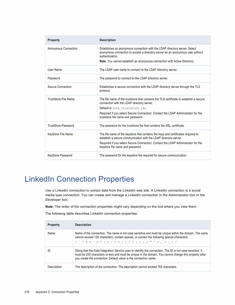
Property Description
Anonymous Connection Establishes an anonymous connection with the LDAP directory server. Select anonymous connection to access a directory server as an anonymous user without authentication.Note: You cannot establish an anonymous connection with Active Directory.
User Name The LDAP user name to connect to the LDAP directory server.
Password The password to connect to the LDAP directory server.
Secure Connection Establishes a secure connection with the LDAP directory server through the TLS protocol.
TrustStore File Name The file name of the truststore that contains the TLS certificate to establish a secure connection with the LDAP directory server.Default is infa_truststore.jks.Required if you select Secure Connection. Contact the LDAP Administrator for the truststore file name and password.
TrustStore Password The password for the truststore file that contains the SSL certificate.
KeyStore File Name The file name of the keystore that contains the keys and certificates required to establish a secure communication with the LDAP directory server.Required if you select Secure Connection. Contact the LDAP Administrator for the keystore file name and password.
KeyStore Password The password for the keystore file required for secure communication.
LinkedIn Connection PropertiesUse a LinkedIn connection to extract data from the LinkedIn web site. A LinkedIn connection is a social media type connection. You can create and manage a LinkedIn connection in the Administrator tool or the Developer tool.
Note: The order of the connection properties might vary depending on the tool where you view them.
The following table describes LinkedIn connection properties:
Property Description
Name Name of the connection. The name is not case sensitive and must be unique within the domain. The name cannot exceed 128 characters, contain spaces, or contain the following special characters:~ ` ! $ % ^ & * ( ) - + = { [ } ] | \ : ; " ' < , > . ? /
ID String that the Data Integration Service uses to identify the connection. The ID is not case sensitive. It must be 255 characters or less and must be unique in the domain. You cannot change this property after you create the connection. Default value is the connection name.
Description The description of the connection. The description cannot exceed 765 characters.
218 Appendix C: Connection Properties

Property Description
Location The domain where you want to create the connection.
Type The connection type. Select LinkedIn.
Do you have OAuth details?
Indicates whether you want to configure OAuth. Select one of the following values:- Yes. Indicates that you have the access token and secret.- No. Launches the OAuth Utility.
Consumer Key The API key that you get when you create the application in LinkedIn. LinkedIn uses the key to identify the application.
Consumer Secret The Secret key that you get when you create the application in LinkedIn. LinkedIn uses the secret to establish ownership of the consumer key.
Access Token Access token that the OAuth Utility returns. The LinkedIn application uses this token instead of the user credentials to access the protected resources.
Access Secret Access secret that the OAuth Utility returns. The secret establishes ownership of a token.
Scope Optional. Permissions for the application. Enter the permissions that you used to configure OAuth.
Microsoft Azure Blob Storage Connection PropertiesWhen you set up a Microsoft Azure Blob Storage connection, you must configure the connection properties.
The following table describes the Microsoft Azure Blob Storage connection properties:
Property Description
Name Name of the Microsoft Azure Blob Storage connection.
ID String that the Data Integration Service uses to identify the connection. The ID is not case sensitive. It must be 255 characters or less and must be unique in the domain. You cannot change this property after you create the connection. Default value is the connection name.
Description Description of the connection.
Location The domain where you want to create the connection.
Type Type of connection. Select AzureBlob.
Microsoft Azure Blob Storage Connection Properties 219

The Connection Details tab contains the connection attributes of the Microsoft Azure Blob Storage connection. The following table describes the connection attributes:
Property Description
Account Name Name of the Microsoft Azure Storage account.
Account Key Microsoft Azure Storage access key.
Container Name Microsoft Azure Blob Storage container name.Note: PowerExchange for Microsoft Azure Blob Storage does not support sub-containers.
Microsoft Azure SQL Data Warehouse Connection Properties
When you set up a Microsoft Azure SQL Data Warehouse connection, you must configure the connection properties.
The following table describes the Microsoft Azure SQL Data Warehouse connection properties:
Property Description
Name The name of the connection. The name is not case sensitive and must be unique within the domain. You can change this property after you create the connection. The name cannot exceed 128 characters, contain spaces, or contain the following special characters: ~ ` ! $ % ^ & * ( ) - + = { [ } ] | \ : ; " ' < , > . ? /
ID String that the Data Integration Service uses to identify the connection. The ID is not case sensitive. It must be 255 characters or less and must be unique in the domain. You cannot change this property after you create the connection. Default value is the connection name.
Description The description of the connection. The description cannot exceed 4,000 characters.
Location The domain where you want to create the connection.
Type The connection type. Select Microsoft Azure SQL Data Warehouse.
The following table describes the properties for metadata access:
Property Description
Azure DW JDBC URL Microsoft Azure Data Warehouse JDBC connection string. For example, you can enter the following connection string: jdbc:sqlserver:// <Server>.database.windows.net:1433;database=<Database>. The Administrator can download the URL from Microsoft Azure portal.
Azure DW JDBC Username
User name to connect to the Microsoft Azure SQL Data Warehouse account. You must have permission to read, write, and truncate data in Microsoft Azure SQL Data Warehouse.
Azure DW JDBC Password
Password to connect to the Microsoft Azure SQL Data Warehouse account.
220 Appendix C: Connection Properties

Property Description
Azure DW Schema Name Name of the schema in Microsoft Azure SQL Data Warehouse.
Azure Blob Account Name
Name of the Microsoft Azure Storage account to stage the files.
Azure Blob Account Key The key that authenticates the access to the Blob storage account.
MS SQL Server Connection PropertiesUse a Microsoft SQL Server connection to access Microsoft SQL Server. A Microsoft SQL Server connection is a connection to a Microsoft SQL Server relational database. You can create and manage a Microsoft SQL Server connection in the Administrator tool or the Developer tool.
Note: The order of the connection properties might vary depending on the tool where you view them.
The following table describes MS SQL Server connection properties:
Property Description
Database Type The database type.
Name Name of the connection. The name is not case sensitive and must be unique within the domain. The name cannot exceed 128 characters, contain spaces, or contain the following special characters:~ ` ! $ % ^ & * ( ) - + = { [ } ] | \ : ; " ' < , > . ? /
ID String that the Data Integration Service uses to identify the connection. The ID is not case sensitive. It must be 255 characters or less and must be unique in the domain. You cannot change this property after you create the connection. Default value is the connection name.
Description The description of the connection. The description cannot exceed 765 characters.
Use trusted connection Enables the application service to use Windows authentication to access the database. The user name that starts the application service must be a valid Windows user with access to the database. By default, this option is cleared.
User Name The database user name. Required if Microsoft SQL Server uses NTLMv1 or NTLMv2 authentication.
Password The password for the database user name. Required if Microsoft SQL Server uses NTLMv1 or NTLMv2 authentication.
Pass-through security enabled Enables pass-through security for the connection. When you enable pass-through security for a connection, the domain uses the client user name and password to log into the corresponding database, instead of the credentials defined in the connection object.
MS SQL Server Connection Properties 221

Property Description
Metadata Access Properties: Connection String
Connection string used to access metadata from the database.Use the following connection string:
jdbc:informatica:sqlserver://<host name>:<port>;DatabaseName=<database name> To test the connection with NTLM authentication, include the following parameters in the connection string:- AuthenticationMethod. The NTLM authentication version to use.
Note: UNIX supports NTLMv1 and NTLMv2 but not NTLM.- Domain. The domain that the SQL server belongs to.The following example shows the connection string for a SQL server that uses NTLMv2 authentication in a NT domain named Informatica.com:
jdbc:informatica:sqlserver://host01:1433;DatabaseName=SQL1;AuthenticationMethod=ntlm2java;Domain=Informatica.com If you connect with NTLM authentication, you can enable the Use trusted connection option in the MS SQL Server connection properties. If you connect with NTLMv1 or NTLMv2 authentication, you must provide the user name and password in the connection properties.
222 Appendix C: Connection Properties

Property Description
AdvancedJDBCSecurityOptions
Database parameters for metadata access to a secure database. Informatica treats the value of the AdvancedJDBCSecurityOptions field as sensitive data and stores the parameter string encrypted.To connect to a secure database, include the following parameters:- EncryptionMethod. Required. Indicates whether data is encrypted when transmitted over
the network. This parameter must be set to SSL.- ValidateServerCertificate. Optional. Indicates whether Informatica validates the certificate
that is sent by the database server.If this parameter is set to True, Informatica validates the certificate that is sent by the database server. If you specify the HostNameInCertificate parameter, Informatica also validates the host name in the certificate.If this parameter is set to false, Informatica does not validate the certificate that is sent by the database server. Informatica ignores any truststore information that you specify.
- HostNameInCertificate. Optional. Host name of the machine that hosts the secure database. If you specify a host name, Informatica validates the host name included in the connection string against the host name in the SSL certificate.
- cryptoProtocolVersion. Optional. If you enable TLS for the Microsoft SQL Server instance, set the cryptoProtocolVersion parameter as follows:cryptoProtocolVersion=TLSv<version number>.For example, cryptoProtocolVersion=TLSv1.2Note: The version number must be the same as the TLS version you configured for the server.
- TrustStore. Required. Path and file name of the truststore file.Note: If you configure SSL or TLS and specify only the file name, you must copy the truststore file to the Informatica installation directory. To test the connection and import metadata, copy the truststore file to the following directory: <Informatica client installation directory>/clients/DeveloperClientTo run the mapping, copy the truststore file to the following directory:<Informatica server installation directory>/tomcat/bin
- TrustStorePassword. Required. Password for the truststore file for the secure database.Not applicable for ODBC.Note: Informatica appends the secure JDBC parameters to the connection string. If you include the secure JDBC parameters directly to the connection string, do not enter any parameters in the AdvancedJDBCSecurityOptions field.
Data Access Properties: Provider Type
The connection provider that you want to use to connect to the Microsoft SQL Server database.You can select the following provider types:- ODBC- Oldeb(Deprecated)Default is ODBC.OLEDB is a deprecated provider type. Support for the OLEDB provider type will be dropped in a future release.
Use DSN Enables the Data Integration Service to use the Data Source Name for the connection.If you select the Use DSN option, the Data Integration Service retrieves the database and server names from the DSN.If you do not select the Use DSN option, you must provide the database and server names.
MS SQL Server Connection Properties 223
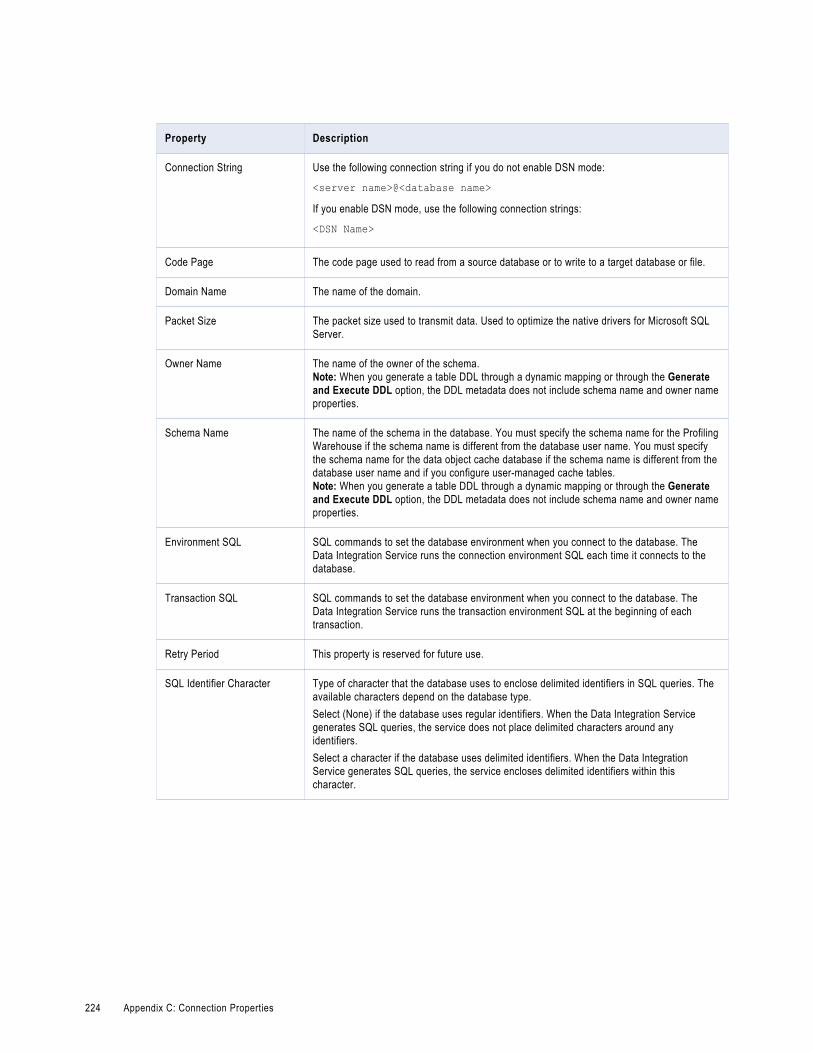
Property Description
Connection String Use the following connection string if you do not enable DSN mode:
<server name>@<database name>If you enable DSN mode, use the following connection strings:
<DSN Name>
Code Page The code page used to read from a source database or to write to a target database or file.
Domain Name The name of the domain.
Packet Size The packet size used to transmit data. Used to optimize the native drivers for Microsoft SQL Server.
Owner Name The name of the owner of the schema.Note: When you generate a table DDL through a dynamic mapping or through the Generate and Execute DDL option, the DDL metadata does not include schema name and owner name properties.
Schema Name The name of the schema in the database. You must specify the schema name for the Profiling Warehouse if the schema name is different from the database user name. You must specify the schema name for the data object cache database if the schema name is different from the database user name and if you configure user-managed cache tables.Note: When you generate a table DDL through a dynamic mapping or through the Generate and Execute DDL option, the DDL metadata does not include schema name and owner name properties.
Environment SQL SQL commands to set the database environment when you connect to the database. The Data Integration Service runs the connection environment SQL each time it connects to the database.
Transaction SQL SQL commands to set the database environment when you connect to the database. The Data Integration Service runs the transaction environment SQL at the beginning of each transaction.
Retry Period This property is reserved for future use.
SQL Identifier Character Type of character that the database uses to enclose delimited identifiers in SQL queries. The available characters depend on the database type.Select (None) if the database uses regular identifiers. When the Data Integration Service generates SQL queries, the service does not place delimited characters around any identifiers.Select a character if the database uses delimited identifiers. When the Data Integration Service generates SQL queries, the service encloses delimited identifiers within this character.
224 Appendix C: Connection Properties

Property Description
Support Mixed-case Identifiers
Enable if the database uses case-sensitive identifiers. When enabled, the Data Integration Service encloses all identifiers within the character selected for the SQL Identifier Character property.When the SQL Identifier Character property is set to none, the Support Mixed-case Identifiers property is disabled.
ODBC Provider ODBC. The type of database to which ODBC connects. For pushdown optimization, specify the database type to enable the Data Integration Service to generate native database SQL. The options are:- Other- Sybase- Microsoft_SQL_ServerDefault is Other.
Netezza Connection PropertiesUse a Netezza connection to access a Netezza database. The Netezza connection is a database connection. You can create and manage a Netezza connection in the Administrator tool or the Developer tool.
Note: The order of the connection properties might vary depending on the tool where you view them.
The following table describes the Netezza connection properties:
Property Description
Name Name of the connection. The name is not case sensitive and must be unique within the domain. The name cannot exceed 128 characters, contain spaces, or contain the following special characters:~ ` ! $ % ^ & * ( ) - + = { [ } ] | \ : ; " ' < , > . ? /
ID String that the Data Integration Service uses to identify the connection. The ID is not case sensitive. It must be 255 characters or less and must be unique in the domain. You cannot change this property after you create the connection. Default value is the connection name.
Description Description of the connection. The description cannot exceed 765 characters.
Location Domain where you want to create the connection.
Type Connection type. Select Netezza.
User name User name with the appropriate permissions to access the Netezza database.
Password Password for the database user name.
JDBC Url JDBC URL that the Developer tool must use when it connects to the Netezza database.Use the following format:jdbc:netezza://<hostname>:<port>/<database name>
Netezza Connection Properties 225

Property Description
Connection String
Name of the ODBC data source that you want to use to connect to the Netezza database.
Timeout Number of seconds that the Developer tool waits for a response from the Netezza database before it closes the connection.
OData Connection PropertiesUse an OData connection to access an OData URL. The OData connection is a Web connection. You can create and manage an OData connection in the Administrator tool or the Developer tool.
Note: The order of the connection properties might vary depending on the tool where you view them.
The following table describes the OData connection properties:
Property Description
Name Name of the connection. The name is not case sensitive and must be unique within the domain. The name cannot exceed 128 characters, contain spaces, or contain the following special characters:~ ` ! $ % ^ & * ( ) - + = { [ } ] | \ : ; " ' < , > . ? /
ID String that the Data Integration Service uses to identify the connection. The ID is not case sensitive. It must be 255 characters or less and must be unique in the domain. You cannot change this property after you create the connection. Default value is the connection name.
Description Description of the connection. The description cannot exceed 4,000 characters.
Location Domain where you want to create the connection.
Type Connection type. Select OData.
User name Optional. User name with the appropriate permissions to read data from the OData resource.
Password Optional. Password for the OData URL user name.
URL OData service root URL that exposes the data that you want to read.
Security Type Optional. Security protocol that the Developer tool must use to establish a secure connection with the OData server.Select one of the following values:- None- SSL- TLSDefault is None.
TrustStore File Name
Required if you select a security type.Name of the truststore file that contains the public certificate for the OData server.Default is infa_truststore.jks.
226 Appendix C: Connection Properties
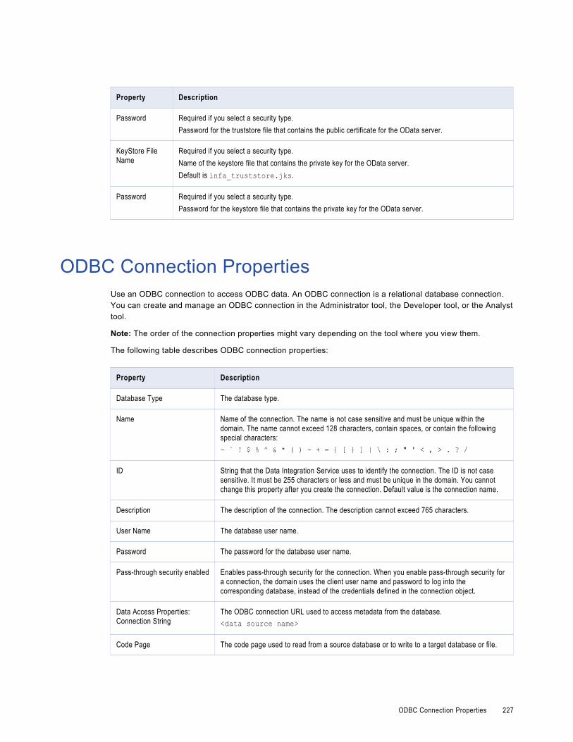
Property Description
Password Required if you select a security type.Password for the truststore file that contains the public certificate for the OData server.
KeyStore File Name
Required if you select a security type.Name of the keystore file that contains the private key for the OData server.Default is infa_truststore.jks.
Password Required if you select a security type.Password for the keystore file that contains the private key for the OData server.
ODBC Connection PropertiesUse an ODBC connection to access ODBC data. An ODBC connection is a relational database connection. You can create and manage an ODBC connection in the Administrator tool, the Developer tool, or the Analyst tool.
Note: The order of the connection properties might vary depending on the tool where you view them.
The following table describes ODBC connection properties:
Property Description
Database Type The database type.
Name Name of the connection. The name is not case sensitive and must be unique within the domain. The name cannot exceed 128 characters, contain spaces, or contain the following special characters:~ ` ! $ % ^ & * ( ) - + = { [ } ] | \ : ; " ' < , > . ? /
ID String that the Data Integration Service uses to identify the connection. The ID is not case sensitive. It must be 255 characters or less and must be unique in the domain. You cannot change this property after you create the connection. Default value is the connection name.
Description The description of the connection. The description cannot exceed 765 characters.
User Name The database user name.
Password The password for the database user name.
Pass-through security enabled Enables pass-through security for the connection. When you enable pass-through security for a connection, the domain uses the client user name and password to log into the corresponding database, instead of the credentials defined in the connection object.
Data Access Properties: Connection String
The ODBC connection URL used to access metadata from the database.<data source name>
Code Page The code page used to read from a source database or to write to a target database or file.
ODBC Connection Properties 227

Property Description
Environment SQL SQL commands to set the database environment when you connect to the database. The Data Integration Service runs the connection environment SQL each time it connects to the database.
Transaction SQL SQL commands to set the database environment when you connect to the database. The Data Integration Service runs the transaction environment SQL at the beginning of each transaction.
Retry Period This property is reserved for future use.
SQL Identifier Character Type of character that the database uses to enclose delimited identifiers in SQL queries. The available characters depend on the database type.Select (None) if the database uses regular identifiers. When the Data Integration Service generates SQL queries, the service does not place delimited characters around any identifiers.Select a character if the database uses delimited identifiers. When the Data Integration Service generates SQL queries, the service encloses delimited identifiers within this character.
Support Mixed-case Identifiers
Enable if the database uses case-sensitive identifiers. When enabled, the Data Integration Service encloses all identifiers within the character selected for the SQL Identifier Character property.When the SQL Identifier Character property is set to none, the Support Mixed-case Identifiers property is disabled.
ODBC Provider The type of database to which ODBC connects. For pushdown optimization, specify the database type to enable the Data Integration Service to generate native database SQL. The options are:- Other- Sybase- Microsoft_SQL_ServerDefault is Other.
Note: Use an ODBC connection to connect to Microsoft SQL Server when the Data Integration Service runs on UNIX or Linux. Use a native connection to Microsoft SQL Server when the Data Integration Service runs on Windows.
Oracle Connection PropertiesUse an Oracle connection to connect to an Oracle database. The Oracle connection is a relational connection type. You can create and manage an Oracle connection in the Administrator tool, the Developer tool, or the Analyst tool.
Note: The order of the connection properties might vary depending on the tool where you view them.
228 Appendix C: Connection Properties

The following table describes Oracle connection properties:
Property Description
Database Type The database type.
Name Name of the connection. The name is not case sensitive and must be unique within the domain. The name cannot exceed 128 characters, contain spaces, or contain the following special characters:~ ` ! $ % ^ & * ( ) - + = { [ } ] | \ : ; " ' < , > . ? /
ID String that the Data Integration Service uses to identify the connection. The ID is not case sensitive. It must be 255 characters or less and must be unique in the domain. You cannot change this property after you create the connection. Default value is the connection name.
Description The description of the connection. The description cannot exceed 765 characters.
User Name The database user name.
Password The password for the database user name.
Pass-through security enabled Enables pass-through security for the connection. When you enable pass-through security for a connection, the domain uses the client user name and password to log into the corresponding database, instead of the credentials defined in the connection object.
Metadata Access Properties: Connection String
Connection string used to access metadata from the database.Use the following connection string:
jdbc:informatica:oracle://<host_name>:<port>;SID=<database name>
Oracle Connection Properties 229

Property Description
AdvancedJDBCSecurityOptions
Database parameters for metadata access to a secure database. Informatica treats the value of the AdvancedJDBCSecurityOptions field as sensitive data and stores the parameter string encrypted.To connect to a secure database, include the following parameters:- EncryptionMethod. Required. Indicates whether data is encrypted when transmitted over
the network. This parameter must be set to SSL.- ValidateServerCertificate. Optional. Indicates whether Informatica validates the certificate
that is sent by the database server.If this parameter is set to True, Informatica validates the certificate that is sent by the database server. If you specify the HostNameInCertificate parameter, Informatica also validates the host name in the certificate.If this parameter is set to false, Informatica does not validate the certificate that is sent by the database server. Informatica ignores any truststore information that you specify.
- HostNameInCertificate. Optional. Host name of the machine that hosts the secure database. If you specify a host name, Informatica validates the host name included in the connection string against the host name in the SSL certificate.
- cryptoProtocolVersion. Optional. If you enable TLS for the Oracle instance, set the cryptoProtocolVersion parameter as follows:cryptoProtocolVersion=TLSv<version number>.For example, cryptoProtocolVersion=TLSv1.2Note: The version number must be the same as the TLS version you configured for the server.
- TrustStore. Required. Path and file name of the truststore file.Note: If you configure SSL or TLS and specify only the file name, you must copy the truststore file to the Informatica installation directory. To test the connection and import metadata, copy the truststore file to the following directory: <Informatica client installation directory>/clients/DeveloperClientTo run the mapping, copy the truststore file to the following directory:<Informatica server installation directory>/tomcat/bin
- TrustStorePassword. Required. Password for the truststore file for the secure database.- KeyStore. Required. Path and file name of the keystore file.- KeyStorePassword. Required. Password for the keystore file for the secure database.Note: Informatica appends the secure JDBC parameters to the connection string. If you include the secure JDBC parameters directly to the connection string, do not enter any parameters in the AdvancedJDBCSecurityOptions field.
Data Access Properties: Connection String
Use the following connection string:
<database name>.world
Code Page The code page used to read from a source database or to write to a target database or file.
Environment SQL SQL commands to set the database environment when you connect to the database. The Data Integration Service runs the connection environment SQL each time it connects to the database.
Transaction SQL SQL commands to set the database environment when you connect to the database. The Data Integration Service runs the transaction environment SQL at the beginning of each transaction.
Retry Period This property is reserved for future use.
230 Appendix C: Connection Properties

Property Description
Enable Parallel Mode Enables parallel processing when loading data into a table in bulk mode. By default, this option is cleared.
SQL Identifier Character Type of character that the database uses to enclose delimited identifiers in SQL queries. The available characters depend on the database type.Select (None) if the database uses regular identifiers. When the Data Integration Service generates SQL queries, the service does not place delimited characters around any identifiers.Select a character if the database uses delimited identifiers. When the Data Integration Service generates SQL queries, the service encloses delimited identifiers within this character.
Support Mixed-case Identifiers
Enable if the database uses case-sensitive identifiers. When enabled, the Data Integration Service encloses all identifiers within the character selected for the SQL Identifier Character property.When the SQL Identifier Character property is set to none, the Support Mixed-case Identifiers property is disabled.
Salesforce Connection PropertiesUse a Salesforce connection to connect to a Salesforce object. The Salesforce connection is an application connection type. You can create and manage a Salesforce connection in the Administrator tool or the Developer tool.
Note: The order of the connection properties might vary depending on the tool where you view them.
The following table describes Salesforce connection properties:
Property Description
Name Name of the connection. The name is not case sensitive and must be unique within the domain. It cannot exceed 128 characters, contain spaces, or contain the following special characters:~ ` ! $ % ^ & * ( ) - + = { [ } ] | \ : ; " ' < , > . ? /
ID String that the Data Integration Service uses to identify the connection. The ID is not case sensitive. It must be 255 characters or less and must be unique in the domain. You cannot change this property after you create the connection. Default value is the connection name.
Description The description of the connection. The description cannot exceed 765 characters.
Location The Informatica domain where you want to create the connection.
Type The connection type. Select Salesforce.
User Name Salesforce user name.
Salesforce Connection Properties 231

Property Description
User Password Password for the Salesforce user name.To access Salesforce outside the trusted network of your organization, you must append a security token to your password to log in to the API or a desktop client.To receive or reset your security token, log in to Salesforce and click Setup > My Personal Information > Reset My Security Token.Password is case sensitive.
Service URL URL of the Salesforce service you want to access. In a test or development environment, you might want to access the Salesforce Sandbox testing environment. For more information about the Salesforce Sandbox, see the Salesforce documentation.
SAP Connection PropertiesUse an SAP connection to access an SAP table or an SAP BW object. The SAP connection is an enterprise application connection. You can create and manage an SAP connection in the Administrator console or the Developer tool.
Note: The order of the connection properties might vary depending on the tool where you view them.
The following table describes the SAP connection properties:
Property Description
Username Required. User name for the SAP source system that you want to access.
Password Required. Password for the user name.
Connection type Required. Type of connection that you want to create.Select one of the following values:- Application. Create an application connection when you want to connect to a specific SAP application
server.- Load balancing. Create a load balancing connection when you want to use SAP load balancing.Default is Application.Based on the connection type you select, the corresponding connection property fields become available in the Connection Details dialog box. The Developer tool greys out the connection property fields that are not applicable for a particular connection type.
Host name Required when you create an SAP application connection.Host name or IP address of the SAP server that you want to connect to.
System number Required when you create an SAP application connection.SAP system number.
Message host name
Required when you create an SAP load balancing connection.Host name of the SAP message server.
R3 name/SysID Required when you create an SAP load balancing connection.Name of the SAP system.
232 Appendix C: Connection Properties

Property Description
Group Required when you create an SAP load balancing connection.Group name of the SAP application server.
Client Required. SAP client number.
Language Optional. Language that you want to use for mappings and workflows.Must be compatible with the Developer tool code page.If you leave this option blank, the Developer tool uses the default language of the SAP system.
Trace Optional. Use this option to track the JCo calls that the SAP system makes. SAP stores the information about the JCo calls in a trace file.Specify one of the following values:- 0. Off- 1. FullDefault is 0.You can access the trace files from the following directories:- <Informatica installation directory>/tomcat/bin directory on the machine where you
installed the Informatica services- <Informatica installation directory>/clients/DeveloperClient directory on the
machine where you installed the Developer tool
Additional parameters
Optional. Enter any other connection parameter that you want to use.Use the following format:<parameter name>=<value>
Staging directory Path in the SAP system where the stage file will be created.
Source directory Path that contains the source file. The path must be accessible to the Data Integration Service.
Use FTP Enables FTP access to SAP.
FTP user Required when you use FTP.User name to connect to the FTP server.
FTP password Required when you use FTP.Password for the FTP user.
FTP host Required when you use FTP.Host name or IP address of the FTP server.Optionally, you can specify a port number from 1 through 65535, inclusive. Default for FTP is 21.Use one of the following syntax to specify the host name:- hostname:port_number- IP address:port_numberWhen you specify a port number, enable that port number for FTP on the host machine.If you enable SFTP, specify a host name or port number for an SFTP server. Default for SFTP is 22.
Retry period Number of seconds that the Data Integration Service attempts to reconnect to the FTP host if the connection fails.If the Data Integration Service cannot reconnect to the FTP host in the retry period, the mapping or workflow fails.Default is 0. A value of 0 indicates an infinite retry period.
SAP Connection Properties 233

Property Description
Use SFTP Enables SFTP access to SAP.
Public key file name
Required when you enable SFTP and the SFTP server uses public key authentication.Public key file path and file name.
Private key file name
Required when you enable SFTP and the SFTP server uses public key authentication.Private key file path and file name.
Private key file name password
Required when you enable SFTP, and the SFTP server uses public key authentication and the private key is encrypted.Password to decrypt the private key file.
Port range for HTTP
HTTP port range that the Data Integration Service must use to read data from the SAP server in streaming mode.Enter the minimum and maximum port numbers with a hyphen as the separator. The minimum and maximum port number can range between 10000 and 65535. You can also specify the port range according to your organization.Default is 10000-65535.
Sequential Connection PropertiesUse a sequential connection to access sequential data sources. You create a sequential connection in the Developer tool. You can manage a sequential connection in the Administrator tool or the Developer tool.
A sequential data source is a data source that PowerExchange can access by using a data map defined with an access method of SEQ. The Data Integration Service connects to the data source through PowerExchange.
Note: The order of the connection properties might vary depending on the tool where you view them.
The following table describes Sequential connection properties:
Option Description
Location Node name for the location of the PowerExchange Listener that connects to the sequential data set. The node name is defined in the first parameter of the NODE statement in the PowerExchange dbmover.cfg configuration file.
User name A user name that has the authority to access the sequential data set.
234 Appendix C: Connection Properties

Option Description
Password Password for the specified user name or a valid PowerExchange passphrase.A PowerExchange passphrase can be from 9 to 128 characters in length and can contain the following characters:- Uppercase and lowercase letters- The numbers 0 to 9- Spaces- The following special characters:’ - ; # \ , . / ! % & * ( ) _ + { } : @ | < > ? Note: The first character is an apostrophe.
Passphrases cannot include single quotation marks (‘), double quotation marks (“), or currency symbols.To use passphrases, ensure that the PowerExchange Listener runs with a security setting of SECURITY=(1,N) or higher in the DBMOVER member. For more information, see "SECURITY Statement" in the PowerExchange Reference Manual.The allowable characters in the IBM IRRPHREX exit do not affect the allowable characters in PowerExchange passphrases.Note: A valid RACF passphrase can be up to 100 characters in length. PowerExchange truncates passphrases longer than 100 characters when passing them to RACF for validation.
Code page Required. Name of the code page to use for reading from or writing to the sequential data set. Usually, this value is an ISO code page name, such as ISO-8859-6.
Pass-through security enabled
Enables pass-through security for the connection.
Encryption type Optional. The type of encryption that the Data Integration Service uses. Select one of the following options:- None- RC2- DESDefault is None.Notes: - Informatica recommends that you use Secure Sockets Layer (SSL) authentication instead of
configuring the Encryption Type and Level connection properties or the ENCRYPT and ENCRYPTLEVEL statements in the DBMOVER configuration file. SSL authentication provides stricter security and is used by several Informatica products.For more information about implementing SSL authentication in a PowerExchange network, see the PowerExchange Reference Manual.
- The values that you select for the Encryption Type and Level connection attributes override the values in the ENCRYPT and ENCRYPTLEVEL statements, if defined, in the DBMOVER configuration file on the Integration Service machine. To enable encryption for a mapping, be sure to select the appropriate connection attributes.
[Encryption] Level If you selected RC2 or DES for Encryption Type, select one of the following options to indicate the encryption level that the Data Integration Service uses:- 1. Use a 56-bit encryption key for DES and RC2.- 2. Use 168-bit triple encryption key for DES, and use a 64-bit encryption key for RC2.- 3. Use 168-bit triple encryption key for DES, and use a 128-bit encryption key for RC2.This option is ignored if you do not select an encryption type.Default is 1.
Sequential Connection Properties 235

Option Description
Pacing size Optional. Amount of data that the source system can pass to the PowerExchange Listener. Set the pacing size if an external application, database, or the Data Integration Service node is a bottleneck. User lower values for faster performance.Minimum value and default value is 0. A value of 0 provides the best performance.
Interpret as rows Optional Select this option to express the pacing size as a number of rows. Clear this option to express the pacing size in kilobytes. By default, this option is not selected and the pacing size is in kilobytes.
Compression Optional. Select this option to enable source data compression. By compressing data, you can decrease the amount of data that Informatica applications send over the network. By default, this option is not selected and compression is disabled.
Offload processing Optional. Controls whether to offload some bulk data processing from the source machine to the Data Integration Service machine. Select one of the following options:- AUTO. The Data Integration Service determines whether to use offload processing.- Yes. Use offload processing.- No. Do not use offload processing.Default is AUTO.
Worker threads Optional. Number of threads that the Data Integration Service uses to process bulk data when offload processing is enabled. For optimal performance, this value should not exceed the number of available processors on the Data Integration Service machine. Valid values are 1 through 64. Default is 0, which disables multithreading.
Array size Optional The number of records in the storage array for the worker threads. This option is applicable when you set the Worker Threads option to a value greater than 0. Valid values are 25 to 100000. Default is 25.
Write mode Optional. Mode in which the Data Integration Service sends data to the PowerExchange Listener. Select one of the following write modes:- CONFIRMWRITEON. Sends data to the PowerExchange Listener and waits for a response
before sending more data. Select this option when error recovery is a priority. However, this option might degrade performance.
- CONFIRMWRITEOFF. Sends data to the PowerExchange Listener without waiting for a response. Use this option if you can reload the target table when an error occurs.
- ASYNCHRONOUSWITHFAULTTOLERANCE. Sends data to the PowerExchange Listener without waiting for a response. This option also enables error detection. This option combines the speed of CONFIRMWRITEOFF and the data integrity of CONFIRMWRITEON.
Default is CONFIRMWRITEON.
Teradata Parallel Transporter Connection PropertiesUse a Teradata PT connection to access Teradata tables. The Teradata PT connection is a database type connection. You can create and manage a Teradata PT connection in the Administrator tool or the Developer tool.
Note: The order of the connection properties might vary depending on the tool where you view them.
236 Appendix C: Connection Properties

The following table describes Teradata PT connection properties:
Property Description
Name Name of the connection. The name is not case sensitive and must be unique within the domain. The name cannot exceed 128 characters, contain spaces, or contain the following special characters:~ ` ! $ % ^ & * ( ) - + = { [ } ] | \ : ; " ' < , > . ? /
ID String that the Data Integration Service uses to identify the connection. The ID is not case sensitive. It must be 255 characters or less and must be unique in the domain. You cannot change this property after you create the connection. Default value is the connection name.
Description Description of the connection. The description cannot exceed 765 characters.
User Name Teradata database user name with the appropriate write permissions to access the database.
Password Password for the Teradata database user name.
Driver Name Name of the Teradata JDBC driver.
Connection String Connection string used to access metadata from the database.Use the following connection string:jdbc:teradata://<hostname>/database=<database name>,tmode=ANSI,charset=UTF8
The following table describes the properties for data access:
Property Description
TDPID Name or IP address of the Teradata database machine.
Database Name Teradata database name.If you do not enter a database name, Teradata PT API uses the default login database name.
Data Code Page Code page associated with the database.When you run a mapping that loads to a Teradata target, the code page of the Teradata PT connection must be the same as the code page of the Teradata target.Default is UTF-8.
Tenacity Number of hours that Teradata PT API continues trying to log on when the maximum number of operations run on the Teradata database.Must be a positive, non-zero integer. Default is 4.
Max Sessions Maximum number of sessions that Teradata PT API establishes with the Teradata database.Must be a positive, non-zero integer. Default is 4.
Teradata Parallel Transporter Connection Properties 237

Property Description
Min Sessions Minimum number of Teradata PT API sessions required for the Teradata PT API job to continue.Must be a positive integer between 1 and the Max Sessions value. Default is 1.
Sleep Number of minutes that Teradata PT API pauses before it retries to log on when the maximum number of operations run on the Teradata database.Must be a positive, non-zero integer. Default is 6.
Use Metadata JDBC URL for TDCH Indicates that the Teradata Connector for Hadoop (TDCH) must use the JDBC URL that you specified in the connection string under the metadata access properties.Default is selected.Clear this option to enter a different JDBC URL that TDCH must use when it runs the mapping.
Data Encryption Enables full security encryption of SQL requests, responses, and data on Windows.To enable data encryption on Unix, add the command UseDataEncryption=Yes to the DSN in the odbc.ini file.Default is disabled.
TDCH JDBC Url Enter the JDBC URL that TDCH must use when it runs a Teradata mapping. Use the following format:jdbc:teradata://<hostname>/database=<database name>,tmode=ANSI,charset=UTF8This field is available only when you clear the Use Metadata JDBC URL for TDCH option.
Twitter Connection PropertiesUse a Twitter connection to extract data from the Twitter web site. The Twitter connection is a connection to social media. You can create and manage a Twitter connection in the Administrator tool or the Developer tool.
Note: The order of the connection properties might vary depending on the tool where you view them.
The following table describes Twitter connection properties:
Property Description
Name Name of the connection. The name is not case sensitive and must be unique within the domain. The name cannot exceed 128 characters, contain spaces, or contain the following special characters:~ ` ! $ % ^ & * ( ) - + = { [ } ] | \ : ; " ' < , > . ? /
ID String that the Data Integration Service uses to identify the connection. The ID is not case sensitive. It must be 255 characters or less and must be unique in the domain. You cannot change this property after you create the connection. Default value is the connection name.
Description The description of the connection. The description cannot exceed 765 characters.
238 Appendix C: Connection Properties

Property Description
Location The domain where you want to create the connection.
Type The connection type. Select Twitter.
Do you have OAuth details?
Indicates whether you want to configure OAuth. Select one of the following values:- Yes. Indicates that you have the access token and secret.- No. Launches the OAuth Utility.
Consumer Key The consumer key that you get when you create the application in Twitter. Twitter uses the key to identify the application.
Consumer Secret The consumer secret that you get when you create the Twitter application. Twitter uses the secret to establish ownership of the consumer key.
Access Token Access token that the OAuth Utility returns. Twitter uses this token instead of the user credentials to access the protected resources.
Access Secret Access secret that the OAuth Utility returns. The secret establishes ownership of a token.
Twitter Streaming Connection PropertiesUse a Twitter Streaming connection to access near-real time data from the Twitter web site. The Twitter Streaming connection is a connection to the social media company's streaming API. You can create and manage a Twitter Streaming connection in the Administrator tool or the Developer tool.
Note: The order of the connection properties might vary depending on the tool where you view them.
The following table describes the general properties for a Twitter Streaming connection:
Property Description
Name Name of the connection. The name is not case sensitive and must be unique within the domain. The name cannot exceed 128 characters, contain spaces, or contain the following special characters:~ ` ! $ % ^ & * ( ) - + = { [ } ] | \ : ; " ' < , > . ? /
ID String that the Data Integration Service uses to identify the connection. The ID is not case sensitive. It must be 255 characters or less and must be unique in the domain. You cannot change this property after you create the connection. Default value is the connection name.
Description The description of the connection. The description cannot exceed 765 characters.
Location The domain where you want to create the connection.
Type The connection type. Select Twitter Streaming.
Twitter Streaming Connection Properties 239

The following table describes the properties for hose type and OAuth authentication:
Property Description
Hose Type Streaming API methods. You can specify one of the following methods:- Filter. The Twitter statuses/filter method returns public statuses that match the search criteria.- Sample. The Twitter statuses/sample method returns a random sample of all public statuses.
Consumer Key The consumer key that you get when you create the application in Twitter. Twitter uses the key to identify the application.
Consumer Secret The consumer secret that you get when you create the Twitter application. Twitter uses the secret to establish ownership of the consumer key.
Do you have OAuth details?
Indicates whether you want to configure OAuth. Select one of the following values:- Yes. Indicates that you have the access token and secret.- No. Launches the OAuth Utility.
Access Token Access token that the OAuth Utility returns. Twitter uses the token instead of the user credentials to access the protected resources.
Access Secret Access secret that the OAuth Utility returns. The secret establishes ownership of a token.
VSAM Connection PropertiesUse a VSAM connection to access VSAM data tables. The VSAM connection is a flat file connection type. You create a VSAM connection in the Developer tool. You can manage a VSAM connection in the Administrator tool or the Developer tool.
Note: The order of the connection properties might vary depending on the tool where you view them.
The following table describes VSAM connection properties:
Option Description
Location Node name for the location of the PowerExchange Listener that connects to the VSAM data set. The node name is defined in the first parameter of the NODE statement in the PowerExchange dbmover.cfg configuration file.
User name A user name that has the authority to connect to the VSAM data set.
240 Appendix C: Connection Properties

Option Description
Password A password for the specified user or a valid PowerExchange passphrase.A PowerExchange passphrase can be from 9 to 128 characters in length and can contain the following characters:- Uppercase and lowercase letters- The numbers 0 to 9- Spaces- The following special characters:’ - ; # \ , . / ! % & * ( ) _ + { } : @ | < > ? Note: The first character is an apostrophe.
Passphrases cannot include single quotation marks (‘), double quotation marks (“), or currency symbols.To use passphrases, ensure that the PowerExchange Listener runs with a security setting of SECURITY=(1,N) or higher in the DBMOVER member. For more information, see "SECURITY Statement" in the PowerExchange Reference Manual.The allowable characters in the IBM IRRPHREX exit do not affect the allowable characters in PowerExchange passphrases.Note: A valid RACF passphrase can be up to 100 characters in length. PowerExchange truncates passphrases longer than 100 characters when passing them to RACF for validation.
Code page Required. Name of the code page to use for reading from or writing to the VSAM data set. Usually, this value is an ISO code page name, such as ISO-8859-6.
Pass-through security enabled
Enables pass-through security for the connection.
Encryption type Optional. The type of encryption that the Data Integration Service uses. Select one of the following options:- None- RC2- DESDefault is None.Notes: - Informatica recommends that you use Secure Sockets Layer (SSL) authentication instead of
configuring the Encryption Type and Level connection properties or the ENCRYPT and ENCRYPTLEVEL statements in the DBMOVER configuration file. SSL authentication provides stricter security and is used by several Informatica products.For more information about implementing SSL authentication in a PowerExchange network, see the PowerExchange Reference Manual.
- The values that you select for the Encryption Type and Level connection attributes override the values in the ENCRYPT and ENCRYPTLEVEL statements, if defined, in the DBMOVER configuration file on the Integration Service machine. To enable encryption for a mapping, be sure to select the appropriate connection attributes.
[Encryption] Level If you selected RC2 or DES for Encryption Type, select one of the following options to indicate the encryption level that the Data Integration Service uses:- 1. Use a 56-bit encryption key for DES and RC2.- 2. Use 168-bit triple encryption key for DES, and use a 64-bit encryption key for RC2.- 3. Use 168-bit triple encryption key for DES, and use a 128-bit encryption key for RC2.This option is ignored if you do not select an encryption type.Default is 1.
VSAM Connection Properties 241
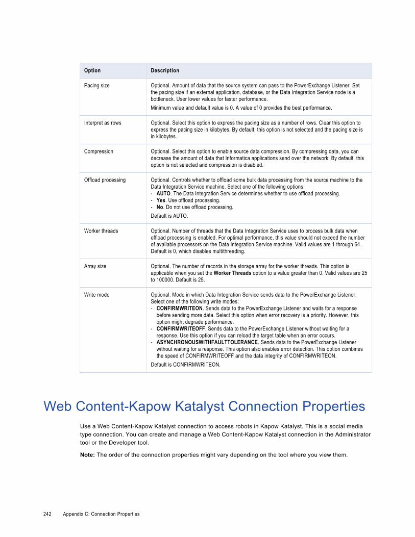
Option Description
Pacing size Optional. Amount of data that the source system can pass to the PowerExchange Listener. Set the pacing size if an external application, database, or the Data Integration Service node is a bottleneck. User lower values for faster performance.Minimum value and default value is 0. A value of 0 provides the best performance.
Interpret as rows Optional. Select this option to express the pacing size as a number of rows. Clear this option to express the pacing size in kilobytes. By default, this option is not selected and the pacing size is in kilobytes.
Compression Optional. Select this option to enable source data compression. By compressing data, you can decrease the amount of data that Informatica applications send over the network. By default, this option is not selected and compression is disabled.
Offload processing Optional. Controls whether to offload some bulk data processing from the source machine to the Data Integration Service machine. Select one of the following options:- AUTO. The Data Integration Service determines whether to use offload processing.- Yes. Use offload processing.- No. Do not use offload processing.Default is AUTO.
Worker threads Optional. Number of threads that the Data Integration Service uses to process bulk data when offload processing is enabled. For optimal performance, this value should not exceed the number of available processors on the Data Integration Service machine. Valid values are 1 through 64. Default is 0, which disables multithreading.
Array size Optional. The number of records in the storage array for the worker threads. This option is applicable when you set the Worker Threads option to a value greater than 0. Valid values are 25 to 100000. Default is 25.
Write mode Optional. Mode in which Data Integration Service sends data to the PowerExchange Listener. Select one of the following write modes:- CONFIRMWRITEON. Sends data to the PowerExchange Listener and waits for a response
before sending more data. Select this option when error recovery is a priority. However, this option might degrade performance.
- CONFIRMWRITEOFF. Sends data to the PowerExchange Listener without waiting for a response. Use this option if you can reload the target table when an error occurs.
- ASYNCHRONOUSWITHFAULTTOLERANCE. Sends data to the PowerExchange Listener without waiting for a response. This option also enables error detection. This option combines the speed of CONFIRMWRITEOFF and the data integrity of CONFIRMWRITEON.
Default is CONFIRMWRITEON.
Web Content-Kapow Katalyst Connection PropertiesUse a Web Content-Kapow Katalyst connection to access robots in Kapow Katalyst. This is a social media type connection. You can create and manage a Web Content-Kapow Katalyst connection in the Administrator tool or the Developer tool.
Note: The order of the connection properties might vary depending on the tool where you view them.
242 Appendix C: Connection Properties

The following table describes Web Content-Kapow Katalyst connection properties:
Property Description
Name Name of the connection. The name is not case sensitive and must be unique within the domain. The name cannot exceed 128 characters, contain spaces, or contain the following special characters:~ ` ! $ % ^ & * ( ) - + = { [ } ] | \ : ; " ' < , > . ? /
ID String that the Data Integration Service uses to identify the connection. The ID is not case sensitive. It must be 255 characters or less and must be unique in the domain. You cannot change this property after you create the connection. Default value is the connection name.
Description The description of the connection. The description cannot exceed 765 characters.
Location The Informatica domain where you want to create the connection.
Type The connection type. Select Web Content-Kapow Katalyst.
Management Console URL URL of the Management Console where the robot is uploaded.The URL must start with http or https. For example, http://localhost:50080.
RQL Service Port The port number where the socket service listens for the RQL service.Enter a value from 1 through 65535. Default is 50000.
Username User name required to access the Local Management Console.
Password Password to access the Local Management Console.
Web Services Connection PropertiesUse a web services connection to connect a Web Service Consumer transformation to a web service.
The following table describes the web services connection properties:
Property Description
Username User name to connect to the web service. Enter a user name if you enable HTTP authentication or WS-Security.If the Web Service Consumer transformation includes WS-Security ports, the transformation receives a dynamic user name through an input port. The Data Integration Service overrides the user name defined in the connection.
Password Password for the user name. Enter a password if you enable HTTP authentication or WS-Security.If the Web Service Consumer transformation includes WS-Security ports, the transformation receives a dynamic password through an input port. The Data Integration Service overrides the password defined in the connection.
Web Services Connection Properties 243

Property Description
End Point URL URL for the web service that you want to access. The Data Integration Service overrides the URL defined in the WSDL file.If the Web Service Consumer transformation includes an endpoint URL port, the transformation dynamically receives the URL through an input port. The Data Integration Service overrides the URL defined in the connection.
Timeout Number of seconds that the Data Integration Service waits for a response from the web service provider before it closes the connection.
HTTP Authentication Type
Type of user authentication over HTTP. Select one of the following values:- None. No authentication.- Automatic. The Data Integration Service chooses the authentication type of the web service provider.- Basic. Requires you to provide a user name and password for the domain of the web service provider.
The Data Integration Service sends the user name and the password to the web service provider for authentication.
- Digest. Requires you to provide a user name and password for the domain of the web service provider. The Data Integration Service generates an encrypted message digest from the user name and password and sends it to the web service provider. The provider generates a temporary value for the user name and password and stores it in the Active Directory on the Domain Controller. It compares the value with the message digest. If they match, the web service provider authenticates you.
- NTLM. Requires you to provide a domain name, server name, or default user name and password. The web service provider authenticates you based on the domain you are connected to. It gets the user name and password from the Windows Domain Controller and compares it with the user name and password that you provide. If they match, the web service provider authenticates you. NTLM authentication does not store encrypted passwords in the Active Directory on the Domain Controller.
WS Security Type Type of WS-Security that you want to use. Select one of the following values:- None. The Data Integration Service does not add a web service security header to the generated
SOAP request.- PasswordText. The Data Integration Service adds a web service security header to the generated
SOAP request. The password is stored in the clear text format.- PasswordDigest. The Data Integration Service adds a web service security header to the generated
SOAP request. The password is stored in a digest form which provides effective protection against replay attacks over the network. The Data Integration Service combines the password with a nonce and a time stamp. The Data Integration Service applies a SHA hash on the password, encodes it in base64 encoding, and uses the encoded password in the SOAP header.
Trust Certificates File
File containing the bundle of trusted certificates that the Data Integration Service uses when authenticating the SSL certificate of the web service. Enter the file name and full directory path.Default is <Informatica installation directory>/services/shared/bin/ca-bundle.crt.
Client Certificate File Name
Client certificate that a web service uses when authenticating a client. Specify the client certificate file if the web service needs to authenticate the Data Integration Service.
Client Certificate Password
Password for the client certificate. Specify the client certificate password if the web service needs to authenticate the Data Integration Service.
Client Certificate Type
Format of the client certificate file. Select one of the following values:- PEM. Files with the .pem extension.- DER. Files with the .cer or .der extension.Specify the client certificate type if the web service needs to authenticate the Data Integration Service.
Private Key File Name
Private key file for the client certificate. Specify the private key file if the web service needs to authenticate the Data Integration Service.
244 Appendix C: Connection Properties

Property Description
Private Key Password
Password for the private key of the client certificate. Specify the private key password if the web service needs to authenticate the Data Integration Service.
Private Key Type Type of the private key. PEM is the supported type.
Identifier Properties in Database ConnectionsWhen you create most relational database connections, you must configure database identifier properties. The identifier properties determine whether the Data Integration Service encloses identifiers within delimited characters when the service generates SQL queries to access the database.
A database identifier is a database object name. Tables, views, columns, indexes, triggers, procedures, constraints, and rules can have identifiers. You use the identifier to reference the object in SQL queries. A database can have regular identifiers or delimited identifiers that must be enclosed within delimited characters.
Regular IdentifiersRegular identifiers comply with the format rules for identifiers. Regular identifiers do not require delimited characters when they are used in SQL queries.
For example, the following SQL statement uses the regular identifiers MYTABLE and MYCOLUMN:
SELECT * FROM MYTABLEWHERE MYCOLUMN = 10
Delimited IdentifiersDelimited identifiers must be enclosed within delimited characters because they do not comply with the format rules for identifiers.
Databases can use the following types of delimited identifiers:
Identifiers that use reserved keywords
If an identifier uses a reserved keyword, you must enclose the identifier within delimited characters in an SQL query. For example, the following SQL statement accesses a table named ORDER:
SELECT * FROM “ORDER”WHERE MYCOLUMN = 10
Identifiers that use special characters
If an identifier uses special characters, you must enclose the identifier within delimited characters in an SQL query. For example, the following SQL statement accesses a table named MYTABLE$@:
SELECT * FROM “MYTABLE$@”WHERE MYCOLUMN = 10
Identifier Properties in Database Connections 245

Case-sensitive identifiers
By default, identifiers in IBM DB2, Microsoft SQL Server, and Oracle databases are not case sensitive. Database object names are stored in uppercase, but SQL queries can use any case to refer to them. For example, the following SQL statements access the table named MYTABLE:
SELECT * FROM mytableSELECT * FROM MyTableSELECT * FROM MYTABLE
To use case-sensitive identifiers, you must enclose the identifier within delimited characters in an SQL query. For example, the following SQL statement accesses a table named MyTable:
SELECT * FROM “MyTable”WHERE MYCOLUMN = 10
Identifier PropertiesWhen you create most database connections, you must configure database identifier properties. The identifier properties that you configure depend on whether the database uses regular identifiers, uses keywords or special characters in identifiers, or uses case-sensitive identifiers.
Configure the following identifier properties in a database connection:
SQL Identifier Character
Type of character that the database uses to enclose delimited identifiers in SQL queries. The available characters depend on the database type.
Select (None) if the database uses regular identifiers. When the Data Integration Service generates SQL queries, the service does not place delimited characters around any identifiers.
Select a character if the database uses delimited identifiers. When the Data Integration Service generates SQL queries, the service encloses delimited identifiers within this character.
Support Mixed-case Identifiers
Enable if the database uses case-sensitive identifiers. When enabled, the Data Integration Service encloses all identifiers within the character selected for the SQL Identifier Character property.
In the Informatica client tools, you must refer to the identifiers with the correct case. For example, when you create the database connection, you must enter the database user name with the correct case.
When the SQL Identifier Character property is set to none, the Support Mixed-case Identifiers property is disabled.
Example: Database Uses Regular IdentifiersIn this example, the database uses regular identifiers. No identifiers contain a reserved keyword or a special character. The database uses identifiers that are not case sensitive.
In the database connection, set the SQL Identifier Character property to (None). When SQL Identifier Character is set to none, the Support Mixed-case Identifiers property is disabled.
When the Data Integration Service generates SQL queries, the service does not place delimited characters around any identifiers.
246 Appendix C: Connection Properties

Example: Database Uses Keywords or Special Characters in IdentifiersIn this example, the database uses keywords or special characters in some identifiers. The database uses identifiers that are not case sensitive.
In the database connection, configure the identifier properties as follows:
1. Set the SQL Identifier Character property to the character that the database uses for delimited identifiers.
This example sets the property to "" (quotes).
2. Clear the Support Mixed-case Identifiers property.
When the Data Integration Service generates SQL queries, the service places the selected character around identifiers that use a reserved keyword or that use a special character. For example, the Data Integration Service generates the following query:
SELECT * FROM "MYTABLE$@" /* identifier with special characters enclosed within delimited character */WHERE MYCOLUMN = 10 /* regular identifier not enclosed within delimited character */
Example: Database Uses Case-Sensitive IdentifiersIn this example, the database uses case-sensitive identifiers. The database might use keywords or special characters in some identifiers, or it might not.
In the database connection, configure the identifier properties as follows:
1. Set the SQL Identifier Character property to the character that the database uses for delimited identifiers.
This example sets the property to "" (quotes).
2. Select the Support Mixed-case Identifiers property.
When the Data Integration Service generates SQL queries, the service places the selected character around all identifiers. For example, the Data Integration Service generates the following query:
SELECT * FROM "MyTable" /* case-sensitive identifier enclosed within delimited character */WHERE "MYCOLUMN" = 10 /* regular identifier enclosed within delimited character */
Identifier Properties in Database Connections 247
Index
AAdabas connections
properties 186application archive file 137applications
creating 139creating an application 134creation 134deploying to a Data Integration Service 136deploying to a file 137exporting to a file 137how to create, deploy, and update 139mapping deployment properties 134overview 133properties 134redeploying 145replacing 138updating 138, 145validating an application 134
attributes relationships 114
Bbigint
constants in expressions 157high precision handling 156using in calculations 156writing to flat files 157
binary datatypes overview 157
business terms customizing hotkeys 41looking up 41
Ccertificates
adding untrusted certificates 83certificate properties 83managing certificates 82untrusted certificates 82
cheat sheets description 19
check in/check out objects 37checking objects out and in 37configurations
troubleshooting 128connection switching
configuring 49data types mapping 51description 48lookup behavior 51
connection switching (continued)postrequisites 50prerequisites 49
connections Connection Explorer view 45creating 46database identifier properties 245deleting 43editing 43overview 43renaming 43switching 43web services properties 243
copy description 26objects 27
custom queries Informatica join syntax 73left outer join syntax 75normal join syntax 74outer join support 73right outer join syntax 77
custom SQL queries creating 78customized data objects 66
customized data objects adding pre- and post-mapping SQL commands 77adding relational data objects 61adding relational resources 61advanced query 67creating 61creating a custom query 78creating key relationships 62creating keys 62custom SQL queries 66default query 67description 58entering source filters 70entering user-defined joins 72key relationships 59pre- and post-mapping SQL commands 77reserved words file 67select distinct 69simple query 67sorted ports 70troubleshooting 84user-defined joins 72using select distinct 70using sorted ports 71write properties 60
DData Integration Service
selecting 21
248

data types decimal 159double 159flat file 163IBM DB2 164Microsoft SQL Server 166ODBC 171Oracle 172transformation 155
data viewer configuration properties 121configurations 121, 124creating configurations 125troubleshooting configurations 128
database connections identifier properties 245
database hints entering in Developer tool 69
DataSift connections properties 188
datatypes DB2 for i5/OS 162Bigint 156binary 157Date/Time 157DB2 for z/OS 162implicit conversion 178Integer 156JDBC 165nonrelational 169overview 154port-to-port data conversion 178SAP HANA 175string 161XML 176
Date/Time datatypes overview 157
DDL Generation DDL Generation Errors 66Generate and Execute DDL 63
decimal high precision handling 156, 159
Decimal data type conversion 178
decimal data types overview 159
default SQL query viewing 78
delimited identifiers database connections 245
delimited properties flat file data objects 89
deployment mapping properties 134overview 133replacing applications 138to a Data Integration Service 141, 142to a file 143to an application archive file 141, 142updating applications 138
Developer tool workspace directory 16
domains adding 20description 21
double high precision handling 159
double data types overview 159
Eerror messages
grouping 131limiting 131
export dependent objects 148objects 149overview 147to a file 143to an application archive file 141, 142XML file 149
FFacebook connections
properties 189filtering object dependencies
object dependencies 130fixed-width properties
flat file data objects 89flat file data objects
advanced properties 87column properties 86creating as empty 99creating from control file 101creating from existing flat file 100delimited properties 89description 85fixed-width properties 89format properties 88general properties 86run-time read properties 91run-time write properties 93
folders creating 26description 26
format properties flat file data objects 88
GGreenplum connections
properties 190
HHBase connections
properties 192HDFS connections
properties 193high precision
Bigint data type 156Decimal data type 156
hints Query view 69
Hive connections properties 193
how to create, deploy, and update an application 139
Index 249

HTTP connections properties 199
IIBM DB2 connections
properties 201IBM DB2 for i5/OS connections
properties 204IBM DB2 for z/OS connections
properties 207identifiers
delimited 245regular 245
identifying relationships description 114
import application archives 144dependent objects 148objects 151overview 147XML file 149
IMS connections properties 210
Informatica Data Services overview 15
Informatica Developer overview 14searches 39setting up 20starting 16
Informatica Marketplace description 20
integers constants in expressions 157using in calculations 156writing to flat files 157
JJD Edwards EnterpriseOne connection
properties 216JDBC connections
properties 213join syntax
customized data objects 73Informatica syntax 73left outer join syntax 75normal join syntax 74right outer join syntax 77
Kkey relationships
creating between relational data objects 57creating in customized data objects 62customized data objects 59relational data objects 56
LLDAP connection
properties 217
LinkedIn connections properties 218
local workspace directory configuring 16
logical data object mappings creating 118read mappings 118types 117write mappings 118
logical data object models creating 105description 105example 104importing 106
logical data objects attribute relationships 114creating 115description 113example 104properties 113
logical view of data developing 104overview 103
logs description 130
look up Business Glossary Desktop 41
Mmappings
configuration properties 121configurations 121, 126creating configurations 127deployment properties 134troubleshooting configurations 128
Microsoft Azure SQL Data Warehouse connection properties 220
Model repository adding 21checking objects out and in 37connecting 38description 29non-versioned 34objects 30search 39searching for objects and properties 40team-based development 34versioned 34versioned objects 34
Model Repository Service refreshing 38
monitoring description 132
MS SQL Server connections properties 221
NNaN
described 157Netezza connections
properties 225non-identifying relationships
description 114
250 Index

nonrelational data objects description 78importing 79
nonrelational data operations creating read, write, and lookup transformations 79
Oobject dependencies
view object dependencies 129Object Dependencies view
viewing data 128objects
copying 27locked objects 32version history 37
OData connections properties 226
ODBC connections properties 227
Oracle connections properties 228
outer join support customized data objects 73
Pperformance tuning
creating data viewer configurations 125creating mapping configurations 127data viewer configurations 124mapping configurations 126web service configurations 127
physical data objects customized data objects 58description 53flat file data objects 85nonrelational data objects 78relational data objects 54synchronization 83troubleshooting 84
pre- and post-mapping SQL commands adding to relational data objects 77customized data objects 77
primary keys creating in customized data objects 62creating in relational data objects 56
project permissions allowing parent object access 25assigning 25dependent object instances 24external object permissions 23grant permission 23read permission 23showing security details 24write permission 23
projects assigning permissions 25creating 22description 22filtering 22permissions 23sharing 22
QQNAN
converting to 1.#QNAN 157Query view
configuring hints 69
Rregular identifiers
database connections 245relational connections
adding to customized data objects 61relational data objects
adding to customized data objects 61creating key relationships 57creating keys 56description 54importing 56key relationships 56troubleshooting 84
reserved words file creating 67customized data objects 67
run-time read properties flat file data objects 91
run-time write properties flat file data objects 93
SSAP connections
properties 232search
overview 39business glossary 40editor 42Model repository 39
select distinct customized data objects 69using in customized data objects 70
self-joins custom SQL queries 66
Sequential connections properties 234
sorted ports customized data objects 70using in customized data objects 71
source filters entering 70
SQL hints entering in Developer tool 69
string datatypes overview 161
synchronization customized data objects 83physical data objects 83
Tteam-based development
troubleshooting 38Teradata Parallel Transporter connections
properties 236
Index 251

transformation data types list of 155
troubleshooting versioning 38
Twitter connections properties 238
Twitter Streaming connections properties 239
Uuser-defined joins
customized data objects 72entering 72Informatica syntax 73left outer join syntax 75normal join syntax 74outer join support 73right outer join syntax 77
Vvalidation
configuring preferences 131grouping error messages 131limiting error messages 131
versioning troubleshooting 38
view object dependencies filtering object dependencies 130
view object dependencies (continued)object dependencies 129
views Connection Explorer view 45description 17
VSAM connections properties 240
Wweb connections
properties 199Web content-Kapow Katalyst connections
properties 242web service
configuration properties 121configurations 127creating configurations 127
Welcome page description 19
workbench description 17
workspace directory configuring 16
WSDL data objects advanced view 81creating 81importing 80overview view 80schema view 80synchronization 81
252 Index