
Determining Situ Deformation Modulus Using a Flexible ... · PDF fileDesignation USBR 6575-09...
26
Designation USBR 6575-09 Determining Situ Deformation Modulus Using a Flexible Volumetric Dilatometer This procedure is under the jurisdiction of the Materials Engineering and Research Laboratory, code 86-68180, Technical Service Center, Denver, Colorado. The procedure is issued under the fixed designation USBR 6575. The number immediately following the designation indicates the first year of acceptance or the year of last revision. 1. Scope 1.1 Explanation.-This designation establishes the guidelines, requirements, procedure, and analyses for determining in situ deformation modulus of a rock mass using a flexible volumetric dilatometer. 1.1.1 This designation applies mainly to the common commercially available volumetric dilatometer for an NX-sized (75.7-millimeters [mm] [2.98-inch (in)]) borehole, but would apply to other dilatometers for different borehole sizes. 1.1.2 This designation is described in the context of obtaining data for designing, constructing, or maintaining Reclamation structures. 1.1.3 This designation focuses on the loading side of the pressure curve with some instruction on the collection of data on the unload cycle. 1.2 Application.-This designation applies to hard and soft rock. Note that while most of the information in this designation may pertain to all flexible dilatometers, this designation is specifically designed for the Probex 1. This probe is mainly used to determine the short-term deformability of rock mass. It can also be used to measure the creep properties of soft rocks, such as salt or potash. 1.3 Test Site.-This method is usually conducted in a vertical or horizontal borehole sized appropriately for the specific dilatometer or as dictated by the data required for the project. Test sites may be either on the surface or underground. 1.4 Units.-Stating the values in Standard Imperial (SI)/metric units is to be regarded as standard. The values given in parenthesis are for information only. 1.5 Caveats. 1.5.1 Safety.-This designation does not purport to address all the safety issues associated with its use and may involve use of hazardous materials, equipment, and operations. The user has the responsibility to establish and adopt appropriate safety and health practices.
Transcript of Determining Situ Deformation Modulus Using a Flexible ... · PDF fileDesignation USBR 6575-09...

Designation USBR 6575-09
Determining Situ Deformation Modulus Using a Flexible Volumetric Dilatometer
This procedure is under the jurisdiction of the Materials Engineering and Research Laboratory, code 86-68180, Technical Service Center, Denver, Colorado. The procedure is issued under the fixed designation USBR 6575. The number immediately following the designation indicates the first year of acceptance or the year of last revision. 1. Scope 1.1 Explanation.-This designation establishes the guidelines, requirements, procedure, and analyses for determining in situ deformation modulus of a rock mass using a flexible volumetric dilatometer. 1.1.1 This designation applies mainly to the common commercially available volumetric dilatometer for an NX-sized (75.7-millimeters [mm] [2.98-inch (in)]) borehole, but would apply to other dilatometers for different borehole sizes. 1.1.2 This designation is described in the context of obtaining data for designing, constructing, or maintaining Reclamation structures. 1.1.3 This designation focuses on the loading side of the pressure curve with some instruction on the collection of data on the unload cycle. 1.2 Application.-This designation applies to hard and soft rock. Note that while most of the information in this designation may pertain to all flexible dilatometers, this designation is specifically designed for the Probex 1. This probe is mainly used
to determine the short-term deformability of rock mass. It can also be used to measure the creep properties of soft rocks, such as salt or potash. 1.3 Test Site.-This method is usually conducted in a vertical or horizontal borehole sized appropriately for the specific dilatometer or as dictated by the data required for the project. Test sites may be either on the surface or underground. 1.4 Units.-Stating the values in Standard Imperial (SI)/metric units is to be regarded as standard. The values given in parenthesis are for information only. 1.5 Caveats. 1.5.1 Safety.-This designation does not purport to address all the safety issues associated with its use and may involve use of hazardous materials, equipment, and operations. The user has the responsibility to establish and adopt appropriate safety and health practices.

USBR 6575-09
2
1.5.2 Codes.-The user must comply with prevalent regulatory codes while using this procedure. 1.5.3 Other manuals.-This designation does not purport to address all of the other details that might be contained in a manufacturer’s manual for a specific dilatometer. The user is responsible for integrating any important details from these manuals. 1.6 Sources.-This designation reflects the information available from American Society for Testing and Materials, International Society for Rock Mechanics Commission on Testing Methods, Reclamation, manufacturer, and other sources. 2. Applicable Documents 2.1 USBR Procedures: USBR 1040 Calibrating Pressure
Gages
USBR 1050 Calibrating Pressure Transducers
USBR 3000 Using Significant
Digits in Calculating and Reporting Laboratory Data
USBR 3910 Standard Terms and
Symbols Relating to Rock Mechanics
USBR 6005 Diamond Core
Drilling, Coring, and Sampling For Site Investigation
USBR 6010 Handling, Storage, Shipment, Inspection, Photographing and Disposition Of Rock Core
USBR 6560 Determining In situ
Deformation Modulus and Creep Characteristics of Rock Mass using a Radial Jacking Method
USBR 6563 Determining In situ
Stress, In situ Deformation Modulus and Creep Characteristics of Rock Mass Using Flatjack Method
USBR 6565 Determining In situ
Deformation Modulus and Creep Characteristics of Rock Mass Using Uniaxial Jacking Test (Flexible Plate Loading) Method
USBR 6570 Determining In situ
Deformation Modulus and Creep Characteristics of Rock Mass Using Diametrically Loaded Borehole Jack Method
USBR 9300 Checking, Rounding,
and Reporting of Laboratory Data
2.2 ASTM Documents.-
Singh, Bhawani, “Reliability of Dilatometer Tests in the Determination of the Modulus of Deformation of a Jointed Rock Mass,” Field Testing and Instrumentation of Rock, ASTM STP 554, ASTM 6032, and American Society for Testing And Materials, pp 52-72, 1973.

USBR 6575-09
3
D6032 Standard Test Method, Determining Rock Quality Designation (RQD) of Rock Core.
2.3 ISRM Suggested Methods.- Suggested Methods for Deformability Determination Using a Flexible Dilatometer, International Society for Rock Mechanics Commission on Testing Methods, Int. J. Rock. Mech. Min. Sci. and Geomech. Abstr., Vol 24, No. 2, pp 123-134, 1987.
2.4 Other Publications.- Franklin, J.A. and Dusseault, M. B., "Dilatometer Tests," Rock Engineering, McGraw-Hill Publishing Company, pp 281-285, 1989. 3. Summary of Method 3.1 Drill Borehole.-An NX borehole is drilled to provide access for the dilatometer device to test the rock mass at selected intervals and locations in the borehole. If the borehole requires support, then cementing, grouting, or casing may be required. 3.2 Set Up Test.-A calibrated flexible dilatometer is lowered in the borehole at a selected test location and a seating pressure is applied hydraulically. 3.3 Conduct Test.-To conduct the test, the dilatometer is expanded by increasing the hydraulic pressure in steps, and corresponding volume changes are recorded for each pressure test. 3.4 Calculate Rock Deformation Properties.-Using the recorded
volume and pressure changes, the in situ modulus of deformation of the rock mass and other rock properties are calculated. 4. Significance and Use 4.1 Input Parameters for Feature Stability.-Prediction of rock mass deformability, creep characteristics, rebound and permanent set have immense engineering significance. The discontinuities that exist in a rock mass, and the genesis, crystallo-graphy, texture, fabric, and other factors may cause the rock mass to behave as an anisotropic, heterogeneous, discontinuous medium. Determination of rock mass deformability yields a critical parameter in the design of foundations of dams, support of underground excavations, and stability of rock slopes. Note 1.-Reclamation also conducts rock mass deformability tests using other designations, such as radial jack tests (USBR 6560), flatjack tests (USBR 6563), flexible plate tests (USBR 6565), and borehole jack tests (USBR 6570). Note 2.-Though a rock mass behaves in an anisotropic and heterogeneous manner, the calculations (see section 13) for a rock mass deformation modulus are based on assumptions of elasticity and homogeneity. However, they still render results that are practical, simple, usable, and not significantly different from those obtained using heterogeneity and inelasticity calculations. The modulus is calculated using an elastic solution for

USBR 6575-09
4
a uniformly applied distributed radial pressure over the dilatometer/rock contact interface (figure 1). 4.2 Rock Mass Behavior.-In situ tests such as this one provide general information regarding rock mass behavior. These tests are important when designing and constructing structures of importance. The dilatometer test is much less expensive and time consuming compared to other deformability tests, such as the radial jack (USBR 6560) or flexible plate tests (USBR 6565). Dilatometer tests can be performed in several boreholes at a reasonable cost and effort. Dilatometer tests provide a qualitative evaluation of a rock mass deformability before performing a larger scale deformability test such as a radial jack test. 4.3 Results for Relevant Structural Design Data.-Results of dilatometer tests are used to provide deformation modulus data for the design and analysis of structures on or in rock. The obtained deformation modulus is commonly less than the elastic modulus determined in the laboratory. Note 3.-The ratio of field to laboratory determined values of modulus of deformation show a wide range of variation, from 1/16 to 1. Note 4.-The dilatometer test is a relatively small scale test and bidirectional at best. The results are good for feasibility or preliminary levels of design. Furthermore, the volume of rock stressed in a dilatometer test is quite small, generally about 0.34 cubic meters
(m3) (12 cubic feet [ft3]), and is often too small for direct application of the results in the final design of a structure. Dilatometer modulus can be correlated with the moduli obtained by other methods (for example, the plate loading or radial jacking methods). The correlated dilatometer modulus can then be used instead of other more expensive, large-scale, in situ modulus tests. Note 5.-Dilatometers are valuable for rapid testing of boreholes in jointed rocks that yield poor core recovery and inadequate specimens for laboratory testing as long as the borehole wall is suitable for testing. Note 6.-The radial displacements of the borehole walls during pressurization are calculated by the total volume change of the dilatometer. As such, the dilatometer test result indicates only the averaged value of the modulus of deformation. Unlike caliper dilatometers, the total volumetric type dilatometer test does not provide information on the anisotropic properties of the rock mass because it cannot measure the specific deformation at a location or orientation. Note 7.-Calculations for modulus of deformation value neglect the in situ stress and stress history of the rock and are outside the scope of this test procedure. Note 8.-Discontinuities can influence the value of the in situ modulus of deformation. The test, therefore, should be located away from the existing discontinuities and

USBR 6575-09
5
preferably in areas of homogeneous rocks, unless required. 4.4 Application Temperatures.-This test method is normally performed at ambient temperatures, but equipment can be modified or substituted for operations at other temperatures. 4.5 Laboratory Testing.-In many cases, laboratory tests may be preferred over or used in conjunction with in situ tests to keep the cost of testing consistent with the required
level of design (for example, during feasibility design, rock mass parameters obtained from index test methods may be sufficient or tests may be used for reasons stated in Note 4). 5. Description of Terms Specific to This Designation 5.1 Discontinuities.-Joints, bedding planes, fractures, and cracks contained in the rock mass.
Figure 1. Radial pressure exerted by a flexible dilatometer membrane

USBR 6575-09
6
5.2 Dilatometer.-A probe with a flexible membrane that is inflated by injecting a suitable fluid in the annular space between a steel core and the flexible membrane until it applies pressure to the borehole walls. 5.3 Flexible Membrane.-An expandable dilatable membrane that is mounted over the steel core of the dilatometer. 5.4 Parasitic Expansion.- Expansion due to the pressure and heat. 5.5 Pressure Correction Factor.-The pressure necessary to expand the probe at a specific volume under atmospheric pressure. This factor is determined by conducting a free expansion test outside any confinement by either a borehole or calibration cylinder that analyzes the influence of the inertia of the membrane. This curve is also called the inertia curve of the membrane. 5.6 Recovery Modulus of Deformation.-A tangent modulus to the unloading stress-strain curve (figure 2). This modulus is usually higher than the other moduli and is used in calculations where unloading conditions exist. Note 9. The difference between the tangent and recovery moduli indicates the material's capacity for hysteresis or energy dissipation capabilities (figure 2). 5.7 Residual Stress.-Stresses that remain in a solid mass after the original cause of the stresses (e.g.,
external forces, heat gradient) has been removed. 5.8 RRU.- Readout reading when membrane is completely retracted or uninflated (undilated). 5.9 RRD .-Readout reading when membrane is completely inflated (dilated). 5.10 Secant Modulus of Deformation.-The slope of a straight line between zero stress and a point on the stress-strain curve at any specified stress (figure 2). This modulus should be used for complete load steps from zero to the desired load.
5.11 Tangent Modulus of Deformation.-The slope of the stress-strain curve obtained over the segment of the loading curve judged as the most representative of elastic response. This modulus neglects the end effects of the curve and is better suited for small stress changes.
Figure 2. - Relationship between tangent, secant, and recovery moduli.

USBR 6575-09
7
Note 10. The ratio between the secant modulus and the tangent modulus can be used to estimate the degree of damage in a material. 5.12 Tectonic Stresses.-Stresses from geological factors such as regional uplift, downward warping, faulting, folding, and others. 5.13 Thermal Stresses.-Stresses from non geologic and geologic factors such as permafrost or natural thermal gradients with depth due to the cooling of the earth’s core or local sources such as magma chambers or batholiths. 5.14 Volume Correction Factor.-The intrinsic volumetric expansion of the probe and the hydraulic components when the probe is pressurized in a medium of infinite rigidity. The factor accounts for any small difference existing between the injected volume that is read on the readout unit and the real volume increase caused by the deformation of the rock tested. 5.15 Other Terms.-See USBR 3910 6. Apparatus 6.1 The Dilatometer System.-The dilatometer, probe (figure 3) is a cylindrical probe with a radially expandable flexible membrane, a dual-action hydraulic module, readout unit with electrical cables, hydraulic pump, gages, transducer, hoses, and a measuring module (figure 3). 6.1.1 The dilatometer is configured to operate in an NX-size (75.7-millimeter [mm] [2.98-inch])
borehole and has a maximum working pressure of 30 Mega Pascals (MPa) (4,350 pounds per square inch [lbf/in2]). 6.1.2 The overall length of the probe including the saturation plug is 749 mm (29.5 in) and its nominal diameter is 73.7 mm (2.9 in). The nominal length on which the membrane can expand is 457 mm (18 in). This configuration gives a length/diameter ratio greater than 6 for the expandable portion of the probe. 6.1.3 A unique characteristic of this dilatometer is that pressurization of the expandable membrane is done immediately upstream from the membrane by movement of a piston actuated from a manual pump at the surface. This dual-action hydraulic module which houses the piston allows the use of the dilatometer at great depths and eliminates the parasitic expansion of the tubing and pumping system. 6.1.4 Volume changes are calculated by recording the displacement of that piston. 6.2 Expandable Dilatometer Probe.-This consists of a dilatometer membrane (shown on figure 3) mounted over a steel core (C). The steel core is fitted with a saturation plug at its downstream extremity. The plug is protected by a conical-shaped end cap that also helps to insert and guide the probe into and down the borehole opening. Water saturation of the system fills the annular space between the dilatable membrane and the steel core as well

USBR 6575-09
8
.
Figure 3.- Schematic representation of the PROBEX-I dilatometer system with
PRO-PR2 readout unit (based on schematics from SMARTEC).

USBR 6575-09
9
as cylinder E. The dual action piston module identified by letters F, G, and H on figure 3 is the mechanism responsible for inflation or deflation of the probe (See 6.3). 6.3 Dual-Action Hydraulic Module.-The dual-action hydraulic module (figure 3) contains two cylinders in which the ends of the piston travel and operated by a manual hydraulic pump. 6.3.1 When the piston is fully retracted, as shown on figure 3, cylinder E is completely filled with water and cylinder EI is filled with oil. With the small handle on the manual pump in the inflation position, oil is pumped immediately behind (upstream) the F end of the piston and the whole piston moves downstream pushing water into the dilatometer probe. Simultaneously, the oil contained within cylinder EI is returned to the hydraulic pump via the deflation line. 6.3.2 To deflate the dilatometer probe, the small handle on the manual pump is placed in the deflation position and the oil is pumped out of cylinder I. The oil previously pumped into the upstream side of piston F in cylinder E is simultaneously returned to the pump via the inflation line and the water that was added is brought back into cylinder E. 6.3.3 The internal diameter of the water cylinder E (figure 3) is 60 mm (2.362 in), and the overall travel of the dual piston is set at 234.9 mm (9.25 in). This geometrical configuration allows a total maximum
volume of water equal to 664.2 cubic centimeters (cm3) (40.53 cubic inches [in3]) to be injected into the probe. Prior to using the dilatometer for testing, complete water and oil saturation (filling) and calibration of the probe is necessary (see section 12). 6.4 Measuring Module.-The measuring module of the dilatometer (figure 3) consists of an LVDT connected to a readout unit via an electric cable. 6.4.1 The LVDT is enclosed in a watertight casing and is fixed to the upstream end of the dual piston and measures the displacement of pistons H and F throughout the loading and unloading process. The LVDT output is powered by, and the output is fed into, the readout unit, which displays a reading corresponding to the position of the piston inside cylinder (E). LVDT characteristics are:
• Linear travel: 12.7 cm (5 in) • Input voltage: 15 volts d.c. • Scale factor: 0.79
volt/centimeter (2 V/in) • Null voltage: 0 volts direct
current (d.c.) • Temperature range: • 54 to 94 °C • (-65 to +200 °F)
6.4.2 The output of the linear variable differential transformer (LVDT) is linear with the displacement of the piston and cylinder (E) has been machined with high precision. Therefore, a calibration constant giving the

USBR 6575-09
10
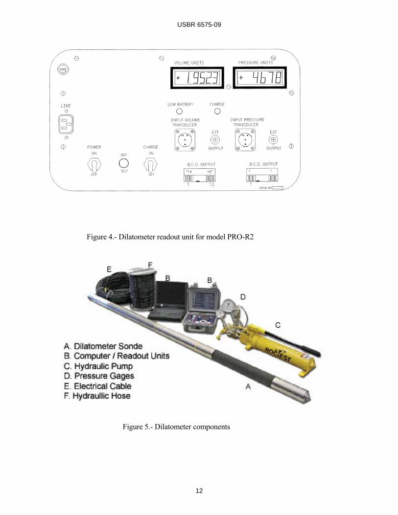
number of cubic centimeters of water injected per unit of output read on the readout unit can be calculated. 6.4.3 Waterproof electrical coaxial cable to provide power and electrical signals between the surface and LVDT cable should be long enough to handle the depths to which the testing is to be performed and should be on some sort of reel system for cable management. 6.5 Readout Unit.-A two-channel portable readout unit equipped with rechargeable batteries is used to indicate the volume change of the probe as well as the oil inflation pressure delivered by the pump. The front panel of the dilatometer readout unit is shown on figure 4. The readout unit can run on batteries (that are rechargeable gel-types) or a line voltage of 110 volts, 60 hertz, or a 220-volt, 50-hertz power supply. The unit has an accuracy of 0.015 percent and a letter height of 13 mm (0.5 in). It weighs 9 kg (20 lb), and its operating range is 0 to 60 °C (32 to 140 °F). Note 11.-Do not operate the readout unit when battery voltage is 5.0 volts or lower. Also, do not operate the readout unit on line operation for more than the battery manufacturer’s recommendation. 6.6 Hydraulic Pump.-A manually operated hydraulic pump with a reservoir capacity of 2.294 liters (140 in3) and a pressure rating of 0 to 70 MPa (0 to 10,000 lbf/in2) comes with a four-way control valve to inflate or deflate the dilatometer flexible
membrane (figure 5). 6.7 Pressure Readouts 6.7.1 Pressure Gages.-Two pressure gages are mounted on the hydraulic pump. The gage control-ling the test pressure is fixed on a metal block mounted on the inflation circuit and has a pressure range of 0 to 35 MPa (0 to 5,000 lbf/in2) and an accuracy of 0.25 percent. 6.7.2 Presssure Transducers.-A second gage is also fixed to a metal block mounted on the deflation circuit. This gage has a smaller pressure range than the gage mounted on the inflation circuit and is provided as a safety feature to prevent over-pressurization of the cylinder upon complete retraction of the dual-acting piston. In addition to the 0 to 35 MPa (0- to 5000 lbf/in2) pressure gage, the inflation line is equipped with a 0- to 35-MPa (0-to 5000-lbf/in2) pressure transducer. For the transducer, the main specifications are:
• Operating pressure range: 0 to 35 MPa (0 to 5,000 lbf/in2)
• Resolution: infinite
• Combined linearity and
hysteresis: 0.1% full scale
• Operating temperature: -20 to +80 °C (-4 to 176 °F)
The pressure transducer comes pre-mounted on the inflation manifold of the hydraulic pump and is read using a readout unit (figure 4) (see section 6.5).

USBR 6575-09
11
USBR 6575-09
12
Figure 4.- Dilatometer readout unit for model PRO-R2
Figure 5.- Dilatometer components
•

USBR 6575-09
13
6.8 Hydraulic Hoses.-High pressure hydraulic lines connect the hydraulic pump to the dilatometer probe. The inflation line has a working pressure of 70 MPa (10,000 lbf/in2) and the deflation line has a maximum working pressure of 32 MPa (4,700 lbf/in2). The outside diameters of the hoses are 8 millimeters (5/16 in). Both the hydraulic hoses and electrical cables may be integrated or bundled together for ease of cable management and insertion into the borehole. 7. Auxiliary Items 7.1 Borehole Drilling and Sampling Equipment.-This equipment includes an assortment of excavation tools, such as drills, drilling rods, drill casings, drill bits, and auxiliary tools for core drilling (76-mm [3.0-in]) diameter test boreholes at designated locations and depths and for raising and lowering the dilatometer in the drill hole. 7.2 Borehole Viewing Device.-Some type of viewing device, such as a borehole video camera, and/or televiewer, is desirable for examination of the conditions and dimensions of the borehole’s internal surface and to compare and verify geologic features observed in the core when the core recovery is poor or when retrieving oriented cores is not feasible. 7.3 Borehole Caliper Gage.-A borehole device that is lowered down and then raised up the borehole and gives a continuous log of the borehole diameter with depth.
A multiple armed, non-averaging device is preferred. 7.4 Calibration Cylinder. Any metallic (typically steel or aluminum) thick wall cylinder with an interior diameter of around 76 mm (3 inches) and can withstand the maximum capacity of the probe. 7.5 Other Equipment • Bucket • Hydraulic oil • Wrenches • Screwdriver • Hammer • Scratch pad • Time clock • Steel and/or aluminum thick wall
calibration cylinder(s) • Polytetrafluoroethylene (PTFE)
tape (also known as “thread seal tape,” “Teflon® tape,” “tape dope,” or “plumber's tape”)
8. Preparation of Apparatus 8.1 Saturation Procedure.- An adequate water saturation (filling) of the dilatometer probe and cylinder E (figure 3) is necessary before conducting any test on rock. This saturation must be undertaken every time the membrane probe is dismounted from the measuring probe (sonde) and when the dilatometer is used for the first time to perform a test. The following saturation procedure must be followed. 8.1.1 Connect the dilatometer to the manual pump with the two hydraulic lines. Also connect the electrical cable leading from the sonde to the volume transducer

USBR 6575-09
14
“Input” connector and the pressure transducer (figure 3). Note 12.-The hydraulic pump and hydraulic module constitute a closed circuit for the oil flow. As such, to avoid potential damage to the hydraulic system, the user must ensure that all four connections to the pump and to the dilatometer sonde are properly made. 8.1.2 Remove the stainless steel conical end cap (A on figure 3) from the dilatometer probe (sonde). 8.1.3 Incline the whole dilatometer (sonde) at about 45 degrees, with the saturation plug at its uppermost point. Turn the probe (sonde) until a small notch made at the end of the steel core (C on figure 3) is in the upper position. This notch, when in line with two small holes made in the steel core, allows the flow of water to cylinder E. Unscrew and remove the saturation plug. 8.1.4 Screw in a small funnel, fitted with an elbow connector, in place of the saturation plug. 8.1.5 Activate the pump by placing the small handle on the manual pump in the inflation position (Number 1). This will displace the dual piston up to the end of its maximum travel or when water appears in the funnel (assuming some water was left in cylinder E). Note 13.-Maximum travel is reached when the volume display on the readout unit stops changing. Discontinue pumping at this stage to
avoid possible damage to the probe (sonde). 8.1.6 Use clean water to fill the funnel. 8.1.7 Change the position of the small handle on the pump to the deflation position Number 2 to activate the pump to bring back the dual piston to its fully retracted position indicated by a constant reading. In doing so, water in the funnel will be sucked into probe. To prevent air from entering, the water must be maintained sufficiently high in the funnel Note 14.-Again, to avoid damage to the probe (sonde), stop pumping when a constant reading is obtained on the readout unit or when a slight pressure increase is seen on the deflation circuit pressure gage. 8.1.8 Place the small handle on the pump in the inflation position (Number 1) and the pump is activated. Any air remaining in the probe will be expelled, and the bubbles will be seen going up in the funnel. Continue this action until the bubbling stops and the water starts rising in the funnel. At this stage, repeat step 8.1.7. If, from the fully retracted position (RRU reading), the downstream movement of the piston does not expel air bubbles through the funnel, saturation is complete. 8.1.9 Remove the funnel and screw the saturation plug back on the steel core, taking care to use PTFE tape on the plug’s threads. Screw the stainless steel conical end cap back on the sonde.

USBR 6575-09
15
8.2 Calibration Procedure.-Calibrate the dilatometer according to section 9 prior to use after any maintenance or suspected damage to the device that could have affected any calibration values. 9. Calibration and Standardization
9.1 Pressure Gages and Transducer.- 9.1.1 Calibrate the pressure gages at frequent intervals (see USBR 1040). 9.1.2 Calibrate the pressure transducer at frequent intervals (see USBR 1050). 9.2 Dilatometer Probe.-Calibrations of the dilatometer probe require a pressure correction factor (see section 9.2.1) and a volume correction factor (see section 9.2.2). Calibration or service of the LVDT may be required but is best left for the manufacturer. Note 14.-The corresponding volume per unit of the readout unit must be determined or as provided in the manufacturer’s instruction manual. Note 15.-The inertia or pressure correction curve must be established for each new membrane mounted on the dilatometer. 9.2.1 Pressure (Inertia) Correction Factor.-Obtain the pressure correction curve (figure 6) as follows: 9.2.1.1 With the whole system
saturated (see section 8), place the probe horizontally on the ground. Inflate and deflate the probe five times to flex the membrane, each time displacing the dual-action piston to approximately its full range. 9.2.1.2 Bring the dual-action piston to the completely retracted position. Note 15.-This is indicated by the fully retracted position (RRU) reading on the readout unit or when a slight pressure increase is seen on the deflation side of the pressure gage. 9.2.1.3 Inflate the probe from the deflated state in steps by injecting water in increments of 50 cm3 (3 in3) from the water chamber (figure 3) into the expandable dilatometer probe chamber. After each volume increment, wait one minute, and then read and record the corresponding pressure increase. 9.2.1.4 Plot the cumulative volume vs pressure curve (figure 6). Note 16.-In most cases of rock modulus testing, the pressure correction will have negligible influence on the test results. 9.2.2 Volume correction factor.- The volume correction factor curve is shown on figure 7. Subtract from the volume injected (shown on the readout unit) the volume losses due to the intrinsic system expansion as follows: 9.2.2.1 With the whole system saturated, place the deflated probe in a calibration tube which can be any

USBR 6575-09
16
Figure 6.- Typical membrane resistance (inertia) plot
Figure 7.- Typical curve of correction of volume losses

USBR 6575-09
17
thick wall metallic tube with an interior diameter of 76 mm (3 in) that meets any other requirements in 9.2.2.2. Note 17.-The manufacturer supplied calibration tube is typically steel with a 76mm (3 in) internal diameter, however other calibration tubes with different stiffness properties and/or diameters may be needed for specific test situations such as testing soft rock or in oversize boreholes. 9.2.2.2 Inflate the probe three or four times in a row up to its maximum working capacity of 30 MPa (4,350 lbf/in2) and deflate. This operation mechanically sets the components of the dilatometer probe subjected to pressure. 9.2.2.3 Inflate the probe in steps of 3.450 MPa (500 lbf/in2) to the maximum working pressure of the dilatometer. At each step of pressure, read and record the corresponding volume displayed on the readout unit after one minute. 9.2.2.4 Deflate probe and repeat step 9.2.2.3 until a series of five calibrations is completed. 9.2.2.5 For each calibration, calculate the injected volume for each pressure step using the volumetric calibration factor, k, specified for the dilatometer. 9.2.2.6 . The correction factor, a, is calculated from the linear part of the curve, and an average value of a is determined from five volume correction factor curves (figure 7).
Note 18.-Two deformation components contribute to the value of a (figure 7):
• Intrinsic volumetric expansion of the dilatometer system, known as c
• Small expansion undergone by the calibration tube during pressurization.
The expansion of the thick-wall metallic tube is determined theoretically and is expressed by the b parameter (see equation 2).
9.2.2.7 The intrinsic volume correction factor, c, cm3/kPa (in3/lbf/in2) is given by equation 1:
where: a =correction factor, cm3/kPa
(in3/lbf/in2) (figure 7) (a is the slope of the linear portion of the curve)
b =calibration cylinder expansion
parameter given by equation 2, cm3/kPa (in3/lbf/in2)
9.2.2.8 The b parameter is calculated with equation 2:
where:
c = a - b 1
b = 2V[ r + e (1+vm)]
Em . e 2

USBR 6575-09
18
V = volume taken by the dilatable membrane of the probe when in contact with the thick walled metallic calibration tube, cm3 (in3)
r = internal radius of the calibration tube, cm (in) e = wall thickness of calibration tube, cm (in) vm = Poisson's ratio of calibration tube
material Em = modulus of elasticity of
calibration tube material, MPa (lbf/in2)
Note 19.-The volume correction factor, c, is in the equation used to calculate the modulus of deformation of the rock (see section 13). A high level of confidence in the calculated modulus therefore depends on the exactness of the c value and of its representativeness of the actual intrinsic deformability of the dilatometer probe during the tests. This is particularly the case when rocks with a high stiffness are tested and the dilatometer will experience small volumetric expansion. The user is therefore encouraged to run at least five volume calibration tests prior to in situ testing. 10. Test Plan 10.1 Pre-test Site Selection 10.1.1 Prior to selecting a test site location, compile and analyze all available surface and subsurface geological data. Prepare a three-dimensional portrayal of these data,
either in plotted form or by construction of a physical model. 10.1.2. A number of factors must be considered when selecting the test site, including:
• Spatial orientation and stress intensity of the loads to be transmitted to the rock mass by the proposed structure
• Various types of material found in the rock mass and the relative volume and location of each
• Spatial orientation of rock discontinuities, such as bedding, foliation, jointing, etc., and their relationship to the applied loads from the structure
• Fracture density of the rock
mass 10.2 Test Sites Selection: 10.2.1 Select drill hole locations, orientations, and depths by taking into account the anticipated rock quality variations and depths of weathering, as well as the requirements of the designs or structures for which the test data are to be used. 10.2.2 Make sure that selected sites are accessible to drill equipment and that all safety and regulation issues are identified and handled accordingly. Use USBR 6005 for guidance. 10.3 Drilling and Preparation:

USBR 6575-09
19
10.3.1 Drill test holes with utmost care to preserve their stability, bearing in mind that during the dilatometer tests, rock fragments, regardless of source, inadvertently wedged between the probe and the drill hole wall can trap the dilatometer permanently. Note 20.-If the boreholes need to be supported, the boreholes may be cemented or grouted and redrilled or cased to properly expose the in situ rock in the test sections for dilatometer tests. 10.3.2 The preferred hole diameter is 0.5 to 3.0 mm (0.02 to 0.12 in) larger than the deflated diameter of the probe. 10.3.3 Check the drill hole with a video camera or caliper log (and/or other borehole logging methods) to avoid placing the probe where damage might be caused by open fissures, voids, or oversized borehole diameter. If a drill hole requires support, casing and/or cementing may be necessary. 10.3.4 Make rock cores available on site for inspection by the dilatometer testing staff, if they were not present during drilling. 10.4 Core Samples: 10.4.1 Drill cores are to be fully logged to record recovery and the characteristics of the rock and jointing as directed by the USBR Geology Manual. 10.4.2 Provide core samples with the curatorial care appropriate to
the purpose of the exploration program, and type of material encountered, as discussed in USBR 6005 and 6010. 10.4.3 Cores shall be logged with special emphasis given to fracture spacing and orientation, and conditions of joint surfaces. Rock quality designation (RQD) should be calculated from the obtained core samples (ASTM 6032). 10.5 Selection of Test Locations. 10.5.1 Within each drill hole, space the tests either at equal intervals or at specified locations in pre-selected geological formations, lithology, or beds. Generally, a continuous log of deformability should be taken along sections of the test hole pertinent to design. For example, a 0.3-, 0.6-, or 1.5-meter (1-, 2-, or 5-ft) test interval may be specified depending on the test hole length and the required resolution. 11. Precautions 11.1 Perform tests so as the maximum working pressure is not exceeded. This is approximately 30 MPa (4,350 lbf/in2) in a borehole of diameter 79.4 millimeters (3-1/8 in) or 20 MPa (3,000 lbf/in2) in a borehole of diameter 82.5 millimeters (3-1/4 in). 11.2 Dilatometer tests are recommended to be run in sections of boreholes which have diameters very close to 76 mm (3.0 in). Performance of the dilatometer will then be enhanced and the risk of damaging the probe will be greatly reduced.

USBR 6575-09
20
11.3 Do not perform this test at locations where the diameter of the hole exceeds 82.5 mm (3-1/4 in). Use a borehole caliper gage or any other borehole device to carefully measure the diameter of the borehole at the test locations prior to testing. 11.4 Before testing, check that all equipment is performing as intended. 12. Procedure 12.1 Dilatometer Test Setup: 12.1.1 Make hydraulic and electrical connections to the manual pump and readout unit and check that the whole system is working well by inflating and deflating the probe. Check the battery charge (if battery is being used for testing). 12.1.2 Check the quality of the selected test location in the borehole using the caliper gage and /or other borehole data or core samples, and adjust if required. 12.1.3 Measure and record distance from center of test membrane to top of dilatometer assembly. 12.1.4 Depending on whether the test hole is vertical or inclined, hoist or manually position the pointed end of the sonde centered with the borehole opening, and the long axis of the dilatometer closely aligned with the borehole axis. Attach one or more sections of drill rod or casing if needed before positioning to facilitate process. 12.1.5 Carefully insert the
dilatometer into borehole until the top of the drill string nears the drill hole collar. Secure the drill string if needed with some sort of device such as a holding dog or foot clamp. Do not use securing device on any portion of the sonde. Record location of dilatometer at this initial stage of insertion. 12.1.6 Attach additional drill rods or casing as needed to the top of the drill string to insert the probe to the required test location. This can be done by keeping track of sections added to the drill string so that the location of the test membrane is known with certainty. This location is to be measured with an accuracy ±5 centimeters (±2 in) and recorded. Note 21.-Tests are usually run from the bottom of the drill hole upwards to minimize the risks of the probe becoming stuck in the borehole. Use of BW size casing is recommended to insert and retract the dilatometer in the borehole. This requires the hoses and cables to be fed through the annular space of each section of casing. This provides the most protection to the apparatus against getting stuck in the borehole. However, it is more awkward and slow to use. When borehole conditions are more favorable, small diameter rods may be used to position the device and the hoses and cables, taped tightly on the outside of those rods. 12.2 Testing: 12.2.1 Pressurize and expand

USBR 6575-09
21
the dilatometer membrane under a pressure just enough to ensure proper and adequate contact with the test hole walls. This seating pressure is to remain as the minimum pressure throughout the test. Record the seating pressure, and if needed, wait for probe to reach temperature equilibrium with the test location. 12.2.2 Increase the pressure in 8-10 approximately equal increments to the maximum value. Smaller increments may be needed for very soft rock. The maximum value shall be as high as possible but no greater than the safe working pressure of the test equipment, taking into consideration the smoothness and diameter of drill hole at the test depth, plus any groundwater pressures. 12.2.3 At each increment, keep the pressure constant while taking readings of pressure and corresponding volume. Record volume versus time to give an indication of whether the rock behavior is time-dependent. Alternatively, the same result can be achieved by keeping the volume of the probe constant (without pumping) and recording the drop in pressure with time. 12.2.4 At the maximum test pressure, keep the applied pressure constant for at least 10 minutes or longer if specified. Readings of volume versus time at constant pressure can be tabulated to determine creep rates. 12.2.5 Volume and pressure readings may then be taken during unloading if specified. Three cycles
of loading and unloading are required in most applications. 12.2.6 Release pressure, volume and pressure readings may then be taken during unloading if specified. Note 22.-Calculations and interpretations of unloading data are not covered by this designation. 12.2.7 Three cycles of loading and unloading are required in most applications, and would require repeating steps 12.2 through 12.5. 12.2.8 Plot a pressure-volume curve and determine its slope (figure 7). 12.2.9 Release pressure and make sure membrane is fully retracted and withdraw or relocate the probe for the next test interval, and repeat steps 12.2.1 to 12.2.8. 13. Calculations 13.1 Equation 3 for the modulus of deformation is based on the application of a uniform radial pressure on a cylindrical cavity in an elastic and homogeneous medium. Theoretically:
where: ER =in situ modulus of rock mass
deformation, MPa (lbf/in2)
3

USBR 6575-09
22
v = Poisson's ratio of rock r = radius of borehole, mm (in) p = pressure, kPa (lbf/in2) Δd=change in diameter, mm (in) Note 23.-The calculations require a value of Poisson's ratio. Laboratory determined Poisson's ratios may be used because they do not significantly differ from those in the field. 13.2 The equation for modulus of deformation, E, using equation 3 and modifying it for the dilatometer, is: xxx where: Vo =at rest volume of probe cm3 (in3)
= 1950 cm3 (119 in3) Vm =average of the injected volume
cm3 (in3) = 0.5 (V1 + V2) ΔV =change in volume, cm3 (in3) = V2
- V1
V2 or V1 =volume at time 2 or time 1, cm3 (in3)
Pb2 - Pb1 = difference in applied pressure in probe at time 2 and time 1, (kPa)
Time 1 = time at start of test Time 2 = time when readings were taken C = volume correction factor,
cm3/kPa (in3/lbf/in2)
Note 24.-Vo of 1950 cm3 (119 in3) is based on a nominal inflatable length of 457 mm (18 in) and a nominal diameter of 73.7 mm (2.9 in). For a more precise value of Vo, measure the inflatable length of the flexible membrane and the deflated diameter of the dilatometer probe. 13.3 Applied Pressure in Probe: Using equations (5) or (6):
Pb = 0.955 Pg + 5.97 Δh, kPa 5
or English units
Pb = 0.955 Pg + 0.264 Δh, lbf/in2 6 where:
Pb = applied pressure in probe, kPa (lbf/in2)
Pg = pressure read at pressure gage on
the hydraulic pump, kPa (lbf/in2)
Δh = difference in elevation between
the manual pump and the center of the dilatometer sonde, m (ft)
13.4 Example of Rock Modulus Calculation for Loading Cycle. Given:
• Test conducted in horizontal hole, therefore ∆h = 0
E = 2(1 + v) (Vo + Vm)
⎝⎜⎜⎜⎜⎛
⎠⎟⎟⎟⎟⎞1
ΔV(Pb2 - Pb1) - c
24

USBR 6575-09
23
• Pb = 0.955 Pg
• Rock Poisson's ratio, v = 0.20
• Volume calibration factor, k = 0.0185 cm3/unit of readout unit (Note: this sample used different probe; Reclamation’s probe has k = 0.1774 cm3/unit)
• At rest volume of probe: Vo = 1,950 cm3
• Thick wall steel tube calibration:
a = 1.19 x 10⁻³ cm3/kPa (figure 7) b = 0.087 x 10⁻³ cm3/kPa (see equation 2)
• Volume correction factor, c:
c = a - b = 1.103 x 10⁻³ cm3/kPa Pressure range selected for modulus calculation:
Pg1 = 13,788 kPa (2,000 lbf/in2) Pg2 = 20,682 kPa (3,000 lbf/in2)
Corresponding volume units units read on readout box:
RRU = + 19,000 units U1 = + 5,335 units U2 = + 2,114 units
Calculations: 1) Injected Volumes: V1 =252.8 cm3, i.e., {(RRU-Ui)
units x 0.0185 cm3/unit of readout}
V2 =312.4 cm3, i.e., {(RRU-U2)
units x 0.0185 cm3/unit of readout}
Vm = 0.5 (V1 + V2) = 282.6 cm3
ΔV = V2 - V1 = 59.6 cm3 2) Applied Pressures in the Probe: Pb1 =0.955 x 2,000 lbf/in2 =
13,167 kPa (1,910 lbf/in2)
Pb2 =0.955 x 3,000 lbf/in2 =
19,751 kPa (2,865 lbf/in2)
ΔPb = Pb2 - Pb1 = 6,584 kPa (955
lbf/in2) 3) Modulus (ER) substituting the values above into equation 4 and Section 13.2):
ER = 667.92 MPa (96,880 lbf/in2) 7 14. Report 14.1 The purpose of this section is to establish the minimum requirements for a complete and usable report. Further details may be added as appropriate, and the order of items may be changed as necessary. An applications section compatible with the format described below should be included. 14.2 Introductory Section of the Report.-The introductory section is intended to present the scope and

USBR 6575-09
24
purpose of the testing program and the characteristics of the material tested. The introductory section includes: 14.2.1 Test Locations.-Include the locations of the test boreholes and locations; preferably including a plan map. 14.2.2 Test Rationale.-Discuss the reasons for selecting the borehole orientation and test locations. 14.2.3 Limitations of the Testing Program.-Discuss the areas of interest which are not covered by the testing program and the limitations of the data within the areas of application in general terms. 14.2.4 Description of the Test Site Geology.-Include a complete geological description of the test site including core logs, core photos of core, photos of prepared test areas, if any; a macroscopic description of the rock types; description of structural features that might affect the test; and diagrams of the geology of the test area and locations. 14.3 Test Method Section: 14.3.1 Equipment and Apparatus.-Detailed list of the equipment actually used for the test, including the drilling equipment, and the name, model number, and basic specifications of each major piece of equipment. 14.3.2 Procedure.-Detailed steps of the procedure actually used for the test.
14.3.3 Variations.-If the actual equipment or procedure varies from the requirements contained in this test method, note each variation and the reasons for it. Also discuss the effect of the variation upon the test results. 14.4 Theoretical Background: 14.4.1 Data Reduction Equations.-All equations used to reduce the data should be clearly presented and fully defined. Note any assumptions inherent in the equations or limitations in their applications. Discuss the effect on the results. 14.4.2 Site-Specific Influences: 14.4.2.1 Assumptions.-Discuss in detail the differences between actual test site conditions and conditions assumed in the data reduction equations. Estimate the effects of such differences on numerical results as much as feasible. 14.4.2.2 Correction Factors.-Fully explain and document any correction factors or correction methods applied to the data. 14.5 Results: 14.5.1 Individual Results Table.-Present a table listing the date, test personnel, test number, rock material/structure, and average modulus values for each test location. Take care to identify the depth interval in the rock mass, stress range for each modulus, and type of modulus value. 14.5.2 Summary Table.-Present a summary table, including

USBR 6575-09
25
the characteristics of the rock materials and the pressure range and which load cycle over which the modulus values were calculated. 14.5.3 Graphic Presentations.-Present a typical average deflection curve for each rock material. 14.5.4 Others.-The following other types of analyses and presentations may be included as appropriate: 14.5.4.1 Define the relationship between modulus and applied stress. 14.5.4.2 Discuss modulus dependence on geology. 14.5.4.3 Present relevant histograms and/or statistics of results, if applicable. 14.5.4.4 Compare with laboratory modulus values or the results of other in situ modulus tests. 14.5.4.5 Compare results to other rock types or previous studies. 14.6 Appended Data.-An appendix is recommended and should include: 14.6.1 A completed test data form for each test. 14.6.2 Plots of deformation versus pressure for each test interval similar to figure 8. 15. Precision and Bias 15.1 Precision.-Because of the nature of rock materials tested by this test method, it is either not feasible or
too costly to produce multiple specimens which have uniform physical properties. The precision and bias cannot be determined because specimens that would yield the same test results cannot be tested.

USBR 6575-09
26
Figure 8. - Plots of pressure versus injected volume


![Earthquake-induced deformation analyses of the Upper San ...5] BKP P m = ′ ba m a σ where B is the bulk modulus, Kg is the shear modulus con-stant, n is the shear modulus exponent](https://static.fdocuments.net/doc/165x107/5ecc9e3b3fff8c554e0e2d22/earthquake-induced-deformation-analyses-of-the-upper-san-5-bkp-p-m-a-ba.jpg)
