
Detector Integrado de Seguridad...
36
R.I.S. ® Integrated Safety Detector R.I.S. ® Integrierte Sicherheitsabmeßvorrichtung R.I.S. ® Détecteur Intègre de Sécurité R.I.S. ® Detector Integrado de Seguridad R.I.S. ® Rilevatore Integrato di Sicurezza ®
Transcript of Detector Integrado de Seguridad...

R.I.S.®Integrated Safety Detector
R.I.S.®Integrierte Sicherheitsabmeßvorrichtung
R.I.S.®Détecteur Intègre de Sécurité
R.I.S.®Detector Integrado de Seguridad
R.I.S.®Rilevatore Integrato di Sicurezza
1 9 9 9
comem ® S.p.A. Strada Statale 11, Signolo 22
36054 MONTEBELLO VIC. NO (VI)Tel. 0444 449311 - Fax 0444 449352 - 440359
http://www.comem.com • e-mail:[email protected] Edig
raf s
rl - E
dizi
one
03/0
7 - C
odic
e 54
100D
2001
®

R.I.S. RILEVATORE INTEGRATO DI SICUREZZA
PRESSIONE TEMPERATURA LIVELLO OLIO FORMAZIONE DI GAS
PRESSOSTATOChiude/apre un circuito alla
pressione regolata ( da 100 a 500 mbar)
TERMOMETRORappresentazione visiva dellatemperatura diretta dell’olio e
massima raggiunta
TERMOSTATO “T2”(allarme)
Chiude/apre un circuito al rag-giungimento della temperaturaregolata(da 30°C a120°C)
SEGNALATORERilevatore visivo di
consistente variazione del livello d’olio con chiusura/apertura circuito elettrico
TERMOSTATO “T1”(sgancio)
Chiude/apre un circuito al raggiungimento della temperatura regolata (da 30 °C a 120 °C)
INDICATORERilevatore visivo di lieve
variazione del livello d’olio
SEGNALATOREChiude/apre un circuito alraggiungimento della max
q.tà di gas prodotta (170 cm3)
max 170 cm3
100 ÷ 500 mbar
30 ÷ 120 °C
30 ÷ 120 °C
30 ÷ 160 °C
Aprire il coperchio posteriorecon entrambe le mani, senzafare leva solo su un lato. Portarea “zero” la manopola di regola-zionedel termostato di allarme(ALARM) segnato con“T2”.
Portare a “zero” la manopola diregolazionedel termostato disgancio (STOP) segnato con“T1”.
Svitare l’oblò di protezione perriazzerare l’indice di massima.
PRESSIONE (Pressostato) :Il dispositivo rileva l’aumento della pressione interna del trasformatore.Il valore di funzionamento può essere regolato in funzione di istruzioni date dalcostruttore del trasformatore.Nel caso di aumento di pressione superiore a quanto previsto dalla regolazionedel pressostato, lo stesso chiude/apre un circuito di allarme.
TEMPERATURA :TERMOSTATO “T2” (ALLARME)
Il dispositivo rileva la temperatura interna dell’olio del trasformatore.Il valore di funzionamento può essere regolato in funzione di istruzioni date dalcostruttore del trasformatore. Nel caso di aumento di temperatura superiore aquanto previsto dalla regolazione del termostato “T2” , lo stesso chiude/apre uncircuito di allarme.
TERMOSTATO “T1” (SGANCIO / STOP)Il dispositivo rileva la temperatura interna dell’olio del trasformatore.Il valore di funzionamento può essere regolato in funzione di istruzioni date dalcostruttore del trasformatore. Nel caso di aumento di temperatura superiore aquanto previsto dalla regolazione del termostato “T1” , lo stesso chiude/apre uncircuito di sgancio.
TERMOMETROIl dispositivo rileva la temperatura interna dell’olio del trasformatore che vienevisualizzata all’esterno del dispositivo attraverso l’oblò di protezione. Il termometro è dotato di indice di massima riazzerabile.
LIVELLO OLIO (Galleggiante) :Il dispositivo rileva la formazione di gas o la variazione del livello olio.-Nel caso di piccole variazioni di livello olio o formazione di gas di scarsa consi-stenza il galleggiante si posizionerà tra le scritte “MIN e MAX” poste sullo schermo.-Nel caso di variazione consistente di livello olio o formazione di gas superiore aquanto previsto il galleggiante si posizionerà sulla scritta“MIN”chiudendo/aprendo un circuito di allarme.-Il gas accumulato viene sfiatato/prelevato dall’apposito rubinetto.
Avvicinare un magnete perma-nente al galleggiante (tra lescritte MIN e MAX) e trascinarloverso il basso fino al raggiungi-mento della scritta MIN.Per ripristinare la corretta posi-zione del galleggiante è neces-sario trascinarlo verso l’alto conun magnete.
Con almeno una minima pres-sione interna del trasformatoredi 100 mbar portare sul minimola manopola di regolazione delpressostato.
GRADO DI PROTEZIONE (CEI - EN 60529) IP 66
GRADO DI TENUTA AGLI URTI (EN 50102) IK 07
TENUTA ALLA NEBBIA SALINA 1000 h
RESISTENZA AI RAGGI ULTRAVIOLETTI (UNI-ISO 4892 / UNI-ISO 4582) 500 h
TENUTA ALLA TEMPERATURA -40 °C ÷ +120 °C
ATTACCO PRESSACAVO (FILO Ø 13 mm FINO A 18 mm) Pg 21
MORSETTIERA (EN 50005 / EN 60947-7-1 / IEC 947-7-1) A NORMA
SEZIONE DEL FILO DA UTILIZZARE SULLA MORSETTIERA FINO A 2,5 mm2
PRESSIONE MASSIMA DI ESERCIZIO 500 mbar
CARATTERISTICHE ELETTRICHE INVOLUCRO ISOLATO
CARATTERISTICHE GENERALI
CORRENTE A.C. D.C.Tipo di circuito OHMICO INDUTTIVO OHMICO INDUTTIVO
(cos ϕϕ >> 0,5) (L/R < 40 ms)
Voltaggio 220 127 24 220 127 24 220 127 24 220 127 24Potere interruzione dei contatti 2A 2A 2A 2A 2A 2A 2A 2A 2A 2A 2A 2ALIVELLO OLIO / RACCOLTA GASPotere interruzione dei contatti 6A 6A 6A 2A 2A 2A 0,6A 0,6A 0,6A 0,6A 0,6A 0,6A
PRESSOSTATOPotere interruzione dei contatti 16A 16A 16A 4A 4A 4A 0,6A 0,6A 0,6A 0,6A 0,6A 0,6A
TERMOSTATI
2 3
PRECISIONE STRUMENTITERMOSTATI PRESSOSTATI TERMOMETRI
± 3% del valore di fondo scala ± 10% del valore di fondo scala ± 3% del valore di fondo scala
SCHEMA ELETTRICO (SECONDO NORMA EN 50005)
TEMP.SGANCIO
“T1”
TEMP.ALLARME
“T2”
PRESSIONE LIVELLOOLIO
DESCRIZIONE FUNZIONI VALORE DI TEST DI VERIFICAMISURA

CONDIZIONI NORMALI DI FUNZIONAMENTO CONDIZIONI ANOMALE (INTERVENTO DEL R.I.S.)
LIVELLO OLIO
IMPOSTAZIONETEMP.
ALARM “T2”
TEMPERATURAOLIO
IMPOSTAZIONETEMP.
STOP “T1”
TEMPERATURAOLIO
IMPOSTAZIONEPRESSIONE
PRESSIONE OLIO
IMPOSTAZIONETEMP.
ALARM “T2”
TEMPERATURAOLIO
IMPOSTAZIONETEMP.
STOP “T1”
TEMPERATURAOLIO
IMPOSTAZIONEPRESSIONE
PRESSIONE OLIO
MAX
MIN
MAX
MIN14 11 12 14 11 12
34 31 32 34 31 32
44 41 4244 41 42
24 21 22
24 21 22
110°C100°C90°C80°C70°C60°C50°C40°C30°C20°C10°C
110°C100°C90°C80°C70°C60°C50°C40°C30°C20°C10°C
110°C100°C90°C80°C70°C60°C50°C40°C30°C20°C10°C
110°C100°C90°C80°C70°C60°C50°C40°C30°C20°C10°C
LIVELLO OLIO
APPLICAZIONE SU CASSONE TRASFORMATORE
- Foro Ø 60 ± 1 su cassone- Guarnizione piana (fornita a corredo)- Staffe di bloccaggio in inox (Q.tà 4 pz fornite a corredo)- Rosette piane UNI 6592 Ø 8,4 in inox (Q.tà 4 pz fornite a corredo)- Rosette elastiche UNI 1751 Ø 8,4 in inox (Q.tà 4 pz fornite a corredo)- Dadi M8 UNI 5588 in inox (Q.tà 4 pz forniti a corredo)Serrare i dadi posizione 1,2,3,4 con coppia 3÷4 Nm in modo incrociato; ripetere l’operazione con la stessa sequenzafino al valore consigliato.Durante il sollevamento del trasformatore, per deformazione del coperchio, potrebbe esserci una perdita d’olio. Si consiglia di utilizzare coperchi con spessore adeguato (6-8 mm min).
ISTRUZIONI DI MONTAGGIO
N°4 PRIGIONIERI A 90°OPPURE
N°3 PRIGIONIERI A 120°
Ø 60 ±130
M8
Ø 97 ±2
COPPIA DI SERRAGGIO 6-8 Nm
(12 Nm max)
TAPPO DI PROTEZIONE
DA TOGLIERE PRIMADELL’INSTALLAZIONE
1
2
3
4
4 5

CONDIZIONI NORMALI DI FUNZIONAMENTO CONDIZIONI ANOMALE (INTERVENTO DEL R.I.S.)
LIVELLO OLIO
IMPOSTAZIONETEMP.
ALARM “T2”
TEMPERATURAOLIO
IMPOSTAZIONETEMP.
STOP “T1”
TEMPERATURAOLIO
IMPOSTAZIONEPRESSIONE
PRESSIONE OLIO
IMPOSTAZIONETEMP.
ALARM “T2”
TEMPERATURAOLIO
IMPOSTAZIONETEMP.
STOP “T1”
TEMPERATURAOLIO
IMPOSTAZIONEPRESSIONE
PRESSIONE OLIO
MAX
MIN
MAX
MIN14 11 12 14 11 12
34 31 32 34 31 32
44 41 4244 41 42
24 21 22
24 21 22
110°C100°C90°C80°C70°C60°C50°C40°C30°C20°C10°C
110°C100°C90°C80°C70°C60°C50°C40°C30°C20°C10°C
110°C100°C90°C80°C70°C60°C50°C40°C30°C20°C10°C
110°C100°C90°C80°C70°C60°C50°C40°C30°C20°C10°C
LIVELLO OLIO
APPLICAZIONE SU CASSONE TRASFORMATORE
- Foro Ø 60 ± 1 su cassone- Guarnizione piana (fornita a corredo)- Staffe di bloccaggio in inox (Q.tà 4 pz fornite a corredo)- Rosette piane UNI 6592 Ø 8,4 in inox (Q.tà 4 pz fornite a corredo)- Rosette elastiche UNI 1751 Ø 8,4 in inox (Q.tà 4 pz fornite a corredo)- Dadi M8 UNI 5588 in inox (Q.tà 4 pz forniti a corredo)Serrare i dadi posizione 1,2,3,4 con coppia 3÷4 Nm in modo incrociato; ripetere l’operazione con la stessa sequenzafino al valore consigliato.Durante il sollevamento del trasformatore, per deformazione del coperchio, potrebbe esserci una perdita d’olio. Si consiglia di utilizzare coperchi con spessore adeguato (6-8 mm min).
ISTRUZIONI DI MONTAGGIO
N°4 PRIGIONIERI A 90°OPPURE
N°3 PRIGIONIERI A 120°
Ø 60 ±1
30
M8
Ø 97 ±2
COPPIA DI SERRAGGIO 6-8 Nm
(12 Nm max)
TAPPO DI PROTEZIONE
DA TOGLIERE PRIMADELL’INSTALLAZIONE
1
2
3
4
4 5

AVVERTENZE PER IL MONTAGGIO E L’USO DEL DISPOSITIVO R.I.S.
- Prima del montaggio del dispositivo, togliere il tappo di protezione dal foro passaggio olio.- Per una perfetta tenuta nel tempo, verificare con massima cura che il piano di appoggio del dispositivo R.I.S., non
abbia deformazioni evidenti, tracce di punti di saldatura o bave di alcun genere.- Per una migliore tenuta si consiglia l’utilizzo di quattro (4) prigionieri.- Proteggere il dispositivo R.I.S., durante la fase di verniciatura del cassone.- Montare il dispositivo dopo il trattamento di essiccazione del trasformatore.- Prima di qualsiasi intervento sul dispositivo togliere la tensione.- Manutenzioni e/o tarature devono essere effettuate solo da personale qualificato.- La COMEM non risponde per danni derivanti da anomalie di montaggio, errate manovre o uso improprio.- All’atto del ricevimento controllare la presenza del certificato di collaudo.- Garanzia 12 mesi.- Non pulire il dispositivo con solventi, benzine ecc., solo con panno asciutto o umido d’acqua.
IMPORTANTE
- Non utilizzare il manicotto filettato 1” del dispositivo per il riempimento del trasformatore ma solamente per il rabboc-co finale a dispositivo montato.
- Riempire d’olio il dispositivo fino a che il galleggiante si porta sulla posizione “MAX”. durante questa fase tenere ilrubinetto di sfiato aperto.
- Controllare sempre, a riempimento completato, la perfetta chiusura del rubinetto di sfiato e del tappo di riempimento.Entrambi devono essere serrati a mano senza l’ausilio di chiavi o attrezzi simili.
- Dopo la regolazione dell’indice di massima del termometro assicurare la chiusura dell’oblo’ serrandolo a mano senzal’ausilio di chiavi o attrezzi simili.
- Verificare il corretto serraggio a tenuta della connessione pressacavo Pg 21.- L’eventuale collegamento al conservatore deve essere effettuato a temperatura ambiante (≈ 23 °C) e rispettando la
coppia di serraggio indicata (max 12 Nm).- In caso di collegamento al conservatore l’attacco al dispositivo R.I.S. deve essere effettuato utilizzando del sigillarac-
cordi tipo “LOCTITE542”.- Nel caso di variazione consistente di livello olio o formazione di gas superiore a quanto previsto il galleggiante si posi-
zionerà sulla scritta “MIN” chiudendo/aprendo un circuito elettrico. Il ripristino del trasformatore deve essere effettua-to aggiungendo olio e sfiatando il gas accumulato e riposizionando il galleggiante (RIARMO) trascinandolo verso l’altocon un magnete.
ISTRUZIONI
Le operazioni si eseguono nel seguente modo:A) Togliere il tappo “2”, avvitare la valvola “3’ con relativo nipplo su rubinetto “1” B) Togliere il cappuccio “C, inserire la pompa “5” mediante l’apposito attacco filettato e girare la leva in posizione OFF.C) La pompa è già predisposta per creare depressione.D) Per il ripristino dei livello olio interno dei dispositivo R.I.S., aprire la leva del rubinetto “1” e aspirare con la pompa“5”. Dopo questa operazione chiudere la leva dei rubinetto “1’.E) Sfiatare la pompa girando la leva in posizione ON.
Se il livello d’olio raggiunto non è sufficiente ripetere le operazioni “W e “E”.Ad operazioni concluse togliere i componenti “5” e “3” e richiudere il dispositivo con il tappo “2”.
ISTRUZIONI PER RIPRISTINO LIVELLO SUL DISPOSITIVO R.I.S.
ISTRUZIONI PER RIPRISTINO LIVELLO SUL DISPOSITIVO R.I.S.
PREMESSA
Il riempimento d’olio dei dispositivo viene eseguito esclusivamente dal costruttore dei trasformatore a temperaturaambiente. Al momento della messa in servizio accertarsi che il dispositivo R.I.S. sia completamente pieno d’olio.Comunque per vari motivi, il livello d’olio può essere inferiore a quello prestabilito.- Se il trasformatore è caldo, a causa dell’alta temperatura ambiente o per r il funzionamento proprio, può aumentare la
pressione interna provocando un visibile calo dei livello d’olio sulla camera del dispositivo. Per ovviare all’ inconve-niente è sufficiente togliere il sigillo dì piombatura sulla leva dei rubinetto I (vedi schema), svitare il tappo 2 non com-pletamente, ruotare leggermente la leva dei rubinetto 1, con conseguente sfiato e innalzamento del livello d’olio fino alriempimento totale. Dopo l’operazione accertarsi di richiudere il tappo 2 e pulire il dispositivo da eventuale olio spurgato.
- Con trasformatore freddo, a causa di un lungo tempo di inattività c/o temperatura esterna inferiore a quella ambiente,può verificarsi il fenomeno di depressione intenta nel trasformatore e di conseguenza, un abbassamento dei livellod’olio visibile sulla camera esterna del dispositivo. Questo inconveniente può essere risolto togliendo l’eventuale sigil-lo di piombatura sul tappo 2, svitando lo stesso, e mediante I’ausilio di un imbuto, ripristinare il livello d’olio lenta-mente fino al riempimento totale dei dispositivo, facendo attenzione a non traboccare. Richiudere il dispositivo con iltappo 6 senza l’utilizzo di attrezzi o chiavi. Una volta ripristinato il livello d’olio sul dispositivo, il trasformatore puòessere messo in funzione. Se non ci fosse disponibilità d’ olio per il rabbocco, la Comem fornisce un set accessoricon pompa già predisposta per creare depressione sul dispositivo, e quindi ripristinare il livello d’olio.
6 7

PRESSURE TEMPERATURE OIL LEVEL GASSING
PRESSURE SWITCHcloses/opens a circuit on
pressure ranging (from 100up to 500 mbar)
THERMOMETERvisual representation of oil
temperature and max. temperature reached
“T2” THERMOSTAT SWITCH(alarm)
closes/opens a circuit at apredetermined
temperature level(from 30 °C up to 120 °C)
DETECTORvisual detector of significant
oil level variation throughclosing/opening of an electric
circuit
“T1” THERMOSTAT SWITCH(stop)
closes/opens a circuit at apredetermined
temperature level(from 30 °C up to 120 °C)
INDICATORvisual indicator of slight
oil level variation
DETECTORcloses/opens a circuit when
the max. gas volume isreached (170 cm3)
R.I.S. INTEGRATED SAFETY DETECTOR
DESCRIPTION AND FUNCTIONS MEASURE CHECKING TESTVALUE
max 170 cm3
100 ÷ 500 mbar
30 ÷ 120 °C
30 ÷ 120 °C
30 ÷ 160 °C
Open the rear cover using bothhands, do not lever at one sideonly. The adjustement knob ofthe alarm switch “T2” should beset to zero.
The adjustement knob of thestop switch “T1” should be setto zero.
The protection window is to beunscrewed so that the pointer shall be set to zero
TEMPERATURE:“T2” THERMOSTAT SWITCH (ALARM)
The feature measures the internal oil temperature of the transformers. The nor-mal operating value is set according to the transformer manufacturers instruc-tions. At a pre set temperature on alarm circuit is triggered via a N/O or N/Cswitch (T2).
“T1” THERMOSTAT SWITCH (STOP)The feature measures the internal oil temperature of the transformers. The nor-mal operating value is set according to the transformer manufacturers instruc-tions. At a pre set temperature on stop circuit is triggered via a N/O or N/C switch (T1).
THERMOMETERThe device measures the internal temperature of the transformer, which shallbe visualized outside the device through the protection window. The thermome-ter is equipped with a zero re-setting pointer.
OIL LEVEL (Float)The device indicates any gas evolvement or oil level variation.-Slight oil level variation or any insignificant gas evolvement is denoted by thefloat position between “MIN” & “MAX” on the display.-At major oil variation level or gas evolvement the float stops at “MIN” andopens/closes the alarm circuit.-Any accumulated gas can be drawn off by the cock provided.
With the internal pressure atleast 100 mbar set the adjustingknob of the pressure switch tominimum.
Locate the magnet close to thefloat (between MAX and MIN).Drawn it downwards until itreaches “MIN”. To reset thefloat to its correct position drawthe magnet upwards and detach.
PRESSURE (Pressure switch)
This feature measures the internal pressure of transformer. The normal level isset according to the transformer manufacturer’s instructions. When pressureexeeds a pre set level the alarm circuit is triggered via a N/O or N/C switch.
CURRENT A.C. D.C.Circuit type OHMIC INDUCTIVE OHMIC INDUCTIVE
(cos ϕϕ >> 0,5) (L/R < 40 ms)
DEGREE OF PROTECTION (CEI-EN 60529) IP 66
DEGREE OF SHOCK TIGHTNESS (EN50102) IK 07
SALT-FOGTIGHT 1000 h
UV-RAY RESISTANCE (UNI-ISO 4892 / UNI-ISO 4582) 500 h
TEMPERATURE RESISTANCE -40 °C ÷ +120 °C
CABLE CONNECTION (WIRE Ø 13 mm UNTILL Ø 18 mm) Pg 21
CABLE BOX (EN 50005 / EN 60947-7-1 / IEC 947-7-1) ACCORDING TO STANDARD
WIRE SECTION TO BE USED ON CLAMP BOX UNTILL 2,5 mm2
MAX. RATED PRESSURE 500 mbar
ELECTRICAL CARACTERISTICS INSULATED ENCLOSURE
GENERAL FEATURES
Voltage 220 127 24 220 127 24 127 48 24 127 48 24Contacts interruption power 2A 2A 2A 2A 2A 2A 2A 2A 2A 2A 2A 2A
OIL LEVEL/GAS BLEEDContacts interruption power 6A 6A 6A 1,5A 1,5A 1,5A 0,6A 0,6A 0,6A 0,6A 0,6A 0,6A
PRESSURE SWITCHContacts interruption power 16A 16A 16A 4A 4A 4A 0,6A 0,6A 0,6A 0,6A 0,6A 0,6A
THERMOSTAT
8 9
TOOLS PRECISIONTHERMOSTATS OVERPRESSURE SWITCHES THERMOMETERS
±3% accuracy tolerance of end scale ±10% accuracy tolerance of end scale ±3% accuracy tolerance of end scale
WIRING DIAGRAM (BY EN 50005 STANDARD)
TEMP.STOP“T1”
TEMP.ALARM
“T2”
PRESSURE OILLEVEL
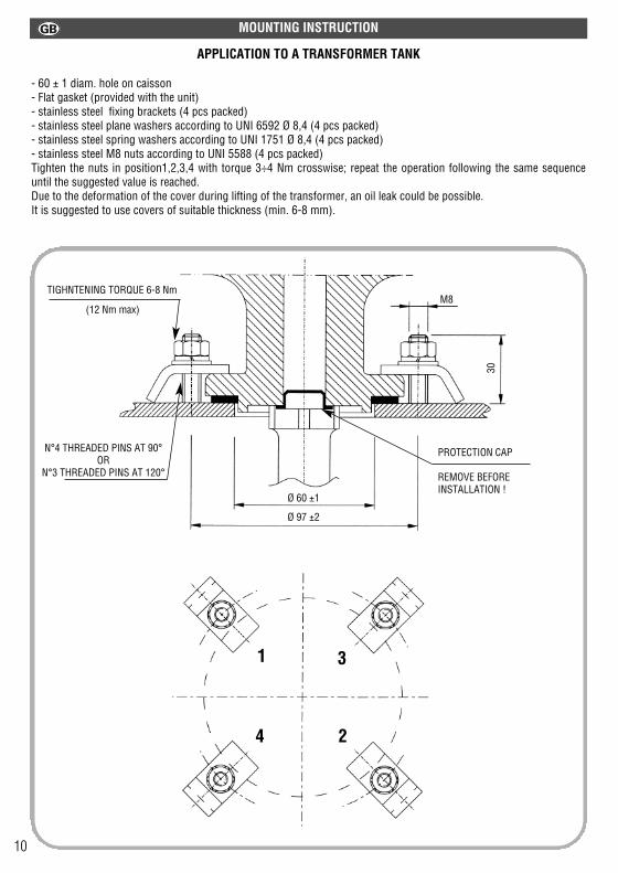
APPLICATION TO A TRANSFORMER TANK
- 60 ± 1 diam. hole on caisson- Flat gasket (provided with the unit)- stainless steel fixing brackets (4 pcs packed)- stainless steel plane washers according to UNI 6592 Ø 8,4 (4 pcs packed)- stainless steel spring washers according to UNI 1751 Ø 8,4 (4 pcs packed)- stainless steel M8 nuts according to UNI 5588 (4 pcs packed)Tighten the nuts in position1,2,3,4 with torque 3÷4 Nm crosswise; repeat the operation following the same sequenceuntil the suggested value is reached. Due to the deformation of the cover during lifting of the transformer, an oil leak could be possible. It is suggested to use covers of suitable thickness (min. 6-8 mm).
MOUNTING INSTRUCTION
N°4 THREADED PINS AT 90°OR
N°3 THREADED PINS AT 120°
Ø 60 ±130
M8
Ø 97 ±2
TIGHNTENING TORQUE 6-8 Nm
(12 Nm max)
PROTECTION CAP
REMOVE BEFOREINSTALLATION !
1
2
3
4
NORMAL WORKING CONDITIONS
OIL LEVEL
TEMP. SETTINGALARM “T2”
OIL TEMP.
TEMP. SETTINGSTOP “T1”
OIL TEMP.
PRESSURE SETTING
OIL PRESSURE
TEMP. SETTINGALARM “T2”
OIL TEMP.
TEMP. SETTINGSTOP “T1”
OIL TEMP.
PRESSURE SETTING
OIL PRESSURE
MAX
MIN
MAX
MIN14 11 12 14 11 12
34 31 32 34 31 32
44 41 4244 41 42
24 21 22
24 21 22
110°C100°C90°C80°C70°C60°C50°C40°C30°C20°C10°C
110°C100°C90°C80°C70°C60°C50°C40°C30°C20°C10°C
110°C100°C90°C80°C70°C60°C50°C40°C30°C20°C10°C
110°C100°C90°C80°C70°C60°C50°C40°C30°C20°C10°C
OIL LEVEL
ANOMALY CONDITIONS (R.I.S. INTERVENTION)
10 11

APPLICATION TO A TRANSFORMER TANK
- 60 ± 1 diam. hole on caisson- Flat gasket (provided with the unit)- stainless steel fixing brackets (4 pcs packed)- stainless steel plane washers according to UNI 6592 Ø 8,4 (4 pcs packed)- stainless steel spring washers according to UNI 1751 Ø 8,4 (4 pcs packed)- stainless steel M8 nuts according to UNI 5588 (4 pcs packed)Tighten the nuts in position1,2,3,4 with torque 3÷4 Nm crosswise; repeat the operation following the same sequenceuntil the suggested value is reached. Due to the deformation of the cover during lifting of the transformer, an oil leak could be possible. It is suggested to use covers of suitable thickness (min. 6-8 mm).
MOUNTING INSTRUCTION
N°4 THREADED PINS AT 90°OR
N°3 THREADED PINS AT 120°
Ø 60 ±1
30
M8
Ø 97 ±2
TIGHNTENING TORQUE 6-8 Nm
(12 Nm max)
PROTECTION CAP
REMOVE BEFOREINSTALLATION !
1
2
3
4
NORMAL WORKING CONDITIONS
OIL LEVEL
TEMP. SETTINGALARM “T2”
OIL TEMP.
TEMP. SETTINGSTOP “T1”
OIL TEMP.
PRESSURE SETTING
OIL PRESSURE
TEMP. SETTINGALARM “T2”
OIL TEMP.
TEMP. SETTINGSTOP “T1”
OIL TEMP.
PRESSURE SETTING
OIL PRESSURE
MAX
MIN
MAX
MIN14 11 12 14 11 12
34 31 32 34 31 32
44 41 4244 41 42
24 21 22
24 21 22
110°C100°C90°C80°C70°C60°C50°C40°C30°C20°C10°C
110°C100°C90°C80°C70°C60°C50°C40°C30°C20°C10°C
110°C100°C90°C80°C70°C60°C50°C40°C30°C20°C10°C
110°C100°C90°C80°C70°C60°C50°C40°C30°C20°C10°C
OIL LEVEL
ANOMALY CONDITIONS (R.I.S. INTERVENTION)
10 11
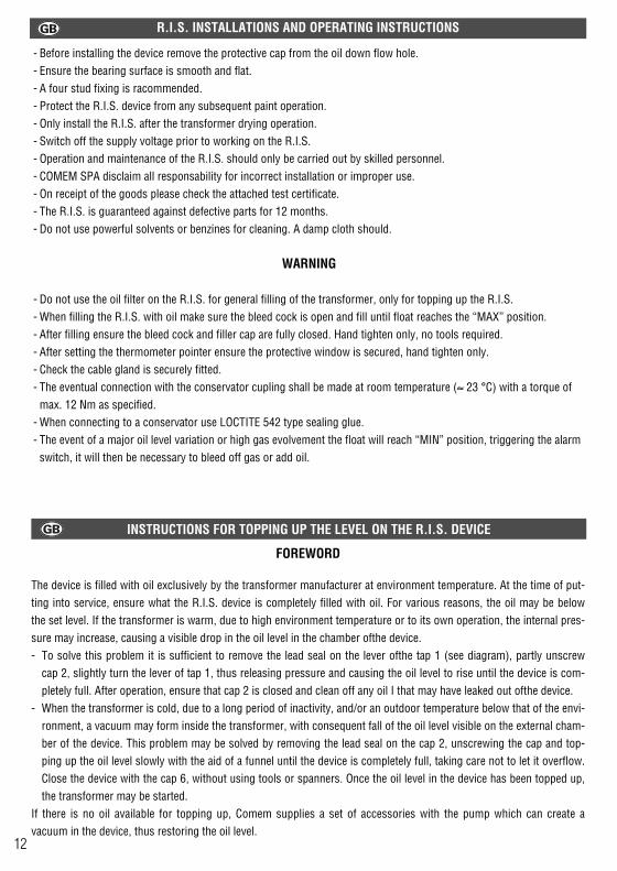
- Before installing the device remove the protective cap from the oil down flow hole.- Ensure the bearing surface is smooth and flat.- A four stud fixing is racommended.- Protect the R.I.S. device from any subsequent paint operation.- Only install the R.I.S. after the transformer drying operation.- Switch off the supply voltage prior to working on the R.I.S.- Operation and maintenance of the R.I.S. should only be carried out by skilled personnel.- COMEM SPA disclaim all responsability for incorrect installation or improper use.- On receipt of the goods please check the attached test certificate.- The R.I.S. is guaranteed against defective parts for 12 months.- Do not use powerful solvents or benzines for cleaning. A damp cloth should.
WARNING
- Do not use the oil filter on the R.I.S. for general filling of the transformer, only for topping up the R.I.S.- When filling the R.I.S. with oil make sure the bleed cock is open and fill until float reaches the “MAX” position.- After filling ensure the bleed cock and filler cap are fully closed. Hand tighten only, no tools required.- After setting the thermometer pointer ensure the protective window is secured, hand tighten only.- Check the cable gland is securely fitted.- The eventual connection with the conservator cupling shall be made at room temperature (≈ 23 °C) with a torque of
max. 12 Nm as specified.- When connecting to a conservator use LOCTITE 542 type sealing glue.- The event of a major oil level variation or high gas evolvement the float will reach “MIN” position, triggering the alarm
switch, it will then be necessary to bleed off gas or add oil.
R.I.S. INSTALLATIONS AND OPERATING INSTRUCTIONS
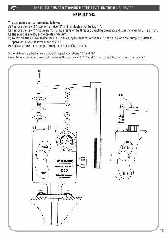
INSTRUCTIONS
The operations are performed as follows:A) Remove the cap “2”, screw the valve “3” and its nipple onto the tap “1”.B) Remove the cap “4”, fit the pump “5” by means of the threaded coupling provided and turn the lever to OFF position.C) The pump is already set to create a vacuum.D)To restore the oil level inside the R.I.S. device, open the lever of the tap “1” and suck with the pump “5”. After this
operation, close the lever of the tap “1”.E) Release air from the pump, turning the lever to ON position.
If the oil level reached is not sufficient, repeat operations “D” and “E”.Once the operations are complete, remove the components “5” and “3” and close the device with the cap “2”.
INSTRUCTIONS FOR TOPPING UP THE LEVEL ON THE R.I.S. DEVICE
INSTRUCTIONS FOR TOPPING UP THE LEVEL ON THE R.I.S. DEVICE
FOREWORD
The device is filled with oil exclusively by the transformer manufacturer at environment temperature. At the time of put-ting into service, ensure what the R.I.S. device is completely filled with oil. For various reasons, the oil may be belowthe set level. If the transformer is warm, due to high environment temperature or to its own operation, the internal pres-sure may increase, causing a visible drop in the oil level in the chamber ofthe device.- To solve this problem it is sufficient to remove the lead seal on the lever ofthe tap 1 (see diagram), partly unscrew
cap 2, slightly turn the lever of tap 1, thus releasing pressure and causing the oil level to rise until the device is com-pletely full. After operation, ensure that cap 2 is closed and clean off any oil I that may have leaked out ofthe device.
- When the transformer is cold, due to a long period of inactivity, and/or an outdoor temperature below that of the envi-ronment, a vacuum may form inside the transformer, with consequent fall of the oil level visible on the external cham-ber of the device. This problem may be solved by removing the lead seal on the cap 2, unscrewing the cap and top-ping up the oil level slowly with the aid of a funnel until the device is completely full, taking care not to let it overflow.Close the device with the cap 6, without using tools or spanners. Once the oil level in the device has been topped up,the transformer may be started.
If there is no oil available for topping up, Comem supplies a set of accessories with the pump which can create avacuum in the device, thus restoring the oil level.
12 13
- Before installing the device remove the protective cap from the oil down flow hole.- Ensure the bearing surface is smooth and flat.- A four stud fixing is racommended.- Protect the R.I.S. device from any subsequent paint operation.- Only install the R.I.S. after the transformer drying operation.- Switch off the supply voltage prior to working on the R.I.S.- Operation and maintenance of the R.I.S. should only be carried out by skilled personnel.- COMEM SPA disclaim all responsability for incorrect installation or improper use.- On receipt of the goods please check the attached test certificate.- The R.I.S. is guaranteed against defective parts for 12 months.- Do not use powerful solvents or benzines for cleaning. A damp cloth should.
WARNING
- Do not use the oil filter on the R.I.S. for general filling of the transformer, only for topping up the R.I.S.- When filling the R.I.S. with oil make sure the bleed cock is open and fill until float reaches the “MAX” position.- After filling ensure the bleed cock and filler cap are fully closed. Hand tighten only, no tools required.- After setting the thermometer pointer ensure the protective window is secured, hand tighten only.- Check the cable gland is securely fitted.- The eventual connection with the conservator cupling shall be made at room temperature (≈ 23 °C) with a torque of
max. 12 Nm as specified.- When connecting to a conservator use LOCTITE 542 type sealing glue.- The event of a major oil level variation or high gas evolvement the float will reach “MIN” position, triggering the alarm
switch, it will then be necessary to bleed off gas or add oil.
R.I.S. INSTALLATIONS AND OPERATING INSTRUCTIONS
INSTRUCTIONS
The operations are performed as follows:A) Remove the cap “2”, screw the valve “3” and its nipple onto the tap “1”.B) Remove the cap “4”, fit the pump “5” by means of the threaded coupling provided and turn the lever to OFF position.C) The pump is already set to create a vacuum.D)To restore the oil level inside the R.I.S. device, open the lever of the tap “1” and suck with the pump “5”. After this
operation, close the lever of the tap “1”.E) Release air from the pump, turning the lever to ON position.
If the oil level reached is not sufficient, repeat operations “D” and “E”.Once the operations are complete, remove the components “5” and “3” and close the device with the cap “2”.
INSTRUCTIONS FOR TOPPING UP THE LEVEL ON THE R.I.S. DEVICE
INSTRUCTIONS FOR TOPPING UP THE LEVEL ON THE R.I.S. DEVICE
FOREWORD
The device is filled with oil exclusively by the transformer manufacturer at environment temperature. At the time of put-ting into service, ensure what the R.I.S. device is completely filled with oil. For various reasons, the oil may be belowthe set level. If the transformer is warm, due to high environment temperature or to its own operation, the internal pres-sure may increase, causing a visible drop in the oil level in the chamber ofthe device.- To solve this problem it is sufficient to remove the lead seal on the lever ofthe tap 1 (see diagram), partly unscrew
cap 2, slightly turn the lever of tap 1, thus releasing pressure and causing the oil level to rise until the device is com-pletely full. After operation, ensure that cap 2 is closed and clean off any oil I that may have leaked out ofthe device.
- When the transformer is cold, due to a long period of inactivity, and/or an outdoor temperature below that of the envi-ronment, a vacuum may form inside the transformer, with consequent fall of the oil level visible on the external cham-ber of the device. This problem may be solved by removing the lead seal on the cap 2, unscrewing the cap and top-ping up the oil level slowly with the aid of a funnel until the device is completely full, taking care not to let it overflow.Close the device with the cap 6, without using tools or spanners. Once the oil level in the device has been topped up,the transformer may be started.
If there is no oil available for topping up, Comem supplies a set of accessories with the pump which can create avacuum in the device, thus restoring the oil level.
12 13

DRUCK TEMPERATUR ÖLNIVEAU GASSTEIGERUNG
DRUCKWÄCHTERschließt/öffnet einen
Stromkreis auf den eingestellenDruck (von 100 bis 500 mbar)
THERMOMETERsichtliche Darstellung der
Öltemperatur und der max.erreichten Temperatur
“T2”THERMOSTAT(Alarm)
schließt/öffnet einenStromkreis als die eingestellte
Temperatur (von 30 °C bis120 °C) erreicht wird
ZEIGERsichtlicher Zeiger von großer
Schwankung im Ölniveaudurch Schließen/Öffnen eines
Stromkreises.
“T1” THERMOSTAT(Stop)
schließt/öffnet einenStromkreis als die eingestellte
Temperatur (von 30 °C bis 120 °C) erreicht wird
ANZEIGERsichtlicher Anzeiger vongeringer Schwankung im
Ölniveau
ZEIGERschließt/öffnet einen Kreis bei
höchster produziertenGasbildung (170 cm3)
R.I.S. INTEGRIERTE SICHERHEITSABMEßVORRICHTUNG
FUNKTIONSBENENNUNG MEßWERTE CHECK-PRÜFUNG
max 170 cm3
100 ÷ 500 mbar
30 ÷ 120 °C
30 ÷ 120 °C
30 ÷ 160 °C
Hinterer Deckel mit beidenHänden aufmachen, ohne nurauf einer Seite zu ziehen.Einstellknopf vom “T2” Alarm-Thermostat nullstellen.
Einstellknopf vom “T1” Stop-Thermostat nullstellen
Schutzfenster auschrauben zurNullstellung des roten Anzeigers
DRUCKDie Vorrichtung meßt die Innentemperatur vom Öl im Trafo.Der Betriebswert darf angeblich der Anweisungen vom Trafo-Hersteller einge-stellt werden. Bei größerer Drucksteigerung nach der Druckwächtereinstellung als erwartet,schließt/öffnet derDruckwächter einen Alarmstromkreis.
TEMPERATUR“T2” THERMOSTAT (Alarm)
Die Vorrichtung meßt die Innentemperatur vom Öl in Trafo.Der Betriebswert darf angeblich der Anweisungen vom Trafo-Hersteller einge-stellt werden. Bei größerer Drucksteigerung nach der Thermostatseinstellung, schließt/öffnet der “T2” Thermostat einenAlarmstromkreis.
“T1” THERMOSTAT (STOP)Die Vorrichtung meßt die Innentemperatur vom Öl in Trafo.Der Betriebwert darf angeblich der Anweisungen vom Trafo-Hersteller einge-stellt werden.Bei größerer Drucksteigerung nach der Thermostatseinstellung als erwartet,schließt/öffnet der “T1” Thermostat einen Auslösungsstromkreis.
THERMOMETERDie Vorrichtung meßt die von außen durch das Schutzfenster sichtbareInnentemperatur vom Öl im Trafo. Der Thermometer ist mit einem nullstellbarroten Anzeiger ausgerüstet.
ÖLNIVEAU (Schwimmer):Die Vorrichtung meßt die Gassteigerung und die Schwankung im Ölniveau.- Bei geringen Schwankungen im Ölniveau oder geringer Gassteigerung stellt sich derSchwimmer zwischen auf die Aufschriften zwischen “MIN” und “MAX” anSchutzhaube.- Bei großen Schwankungen im Ölniveau oder stärkerer Gassteigerung als erwartet,stellt sich der Schwimmer auf “MIN” und dadurch wird ein Alarmstromkreis geschlossen und geöffnet.- Das aufgespeicherte Gas wird durch das geeignete Entlüftungsventil etnommen undabgesaugt.
Dem Schwimmer einenPermanent-Magnet (zwischen denAufschriften MIN und MAX) undihm nach unten bis an dieAufschrift MIN ziehen. DerSchwimmer darf hinaufgetriebenwerden, um ihn an die richtigeStelle wieder zu sëtzen ein Magnetentfernen.
Bei einen min. Innendruck desTrafos von mindstens 100 mbarden Einstellknopf desDruckwächters auf die “MIN”stellen.
SCHUTZGRAD (CEI - EN 60529) IP 66
SHOCKFESTIGKEIT (EN 50102) IK 07
SALZSPRÜHNEBELFESTIGKEIT 1000 h
UV-STRAHLENFESTIGKEIT (UNI-ISO 4892 / UNI-ISO 4582) 500 h
TEMPERATURBESTÄNDIGKEIT -40 °C ÷ +120 °C
KLEMMENKASTENANSCHLUß (DRAHT Ø 13 mm BIS ZU Ø 18 mm) Pg 21
KLEMMKASTEN (EN 50005 / EN 60947-7-1 / IEC 947-7-1) VORSCHRIFTSMÄßIG
AM KLEMMKASTEN VERWENDBARER DRAHTQUERSCHNITT BIS ZU 2,5 mm2
MAX. BETRIEBSDRUCK 500 mbar
ELEKTRISCHE EIGENSCHAFTEN ISOLIERTE HÜLLE
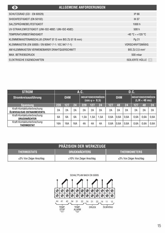
ALLGEMEINE ANFORDERUNGEN
STROM A.C. D.C.INDUKTIONSVERMÖGEN INDUKTIONSVERMÖGENStromkreisausführung OHM OHM
(cos ϕϕ >> 0,5) (L/R < 40 ms)
Spannung 220 127 24 220 127 24 127 48 24 127 48 24Kraft-Kontaktunterbrechung 2A 2A 2A 2A 2A 2A 2A 2A 2A 2A 2A 2A
ÖLNIVEAU/GAS ENTNAHMEVENTIL Kraft-Kontaktunterbrechung 6A 6A 6A 1,5A 1,5A 1,5A 0,6A 0,6A 0,6A 0,6A 0,6A 0,6A
DRUCKWÄCHTERKraft-Kontaktunterbrechung 16A 16A 16A 4A 4A 4A 0,6A 0,6A 0,6A 0,6A 0,6A 0,6A
THERMOSTAT
14 15
PRÄZISION DER WERKZEUGETHERMOSTATS DRUCKWÄCHTERS THERMOMETERS
±3% Von Zeiger Anschlag ±10% Von Zeiger Anschlag ±3% Von Zeiger Anschlag
SCHALTPLAN NACH EN 50005
TEMP.STOP“T1”
TEMP.ALARM
“T2”
DRUCK ÖLNIVEAU
DRUCK TEMPERATUR ÖLNIVEAU GASSTEIGERUNG
DRUCKWÄCHTERschließt/öffnet einen
Stromkreis auf den eingestellenDruck (von 100 bis 500 mbar)
THERMOMETERsichtliche Darstellung der
Öltemperatur und der max.erreichten Temperatur
“T2”THERMOSTAT(Alarm)
schließt/öffnet einenStromkreis als die eingestellte
Temperatur (von 30 °C bis120 °C) erreicht wird
ZEIGERsichtlicher Zeiger von großer
Schwankung im Ölniveaudurch Schließen/Öffnen eines
Stromkreises.
“T1” THERMOSTAT(Stop)
schließt/öffnet einenStromkreis als die eingestellte
Temperatur (von 30 °C bis 120 °C) erreicht wird
ANZEIGERsichtlicher Anzeiger vongeringer Schwankung im
Ölniveau
ZEIGERschließt/öffnet einen Kreis bei
höchster produziertenGasbildung (170 cm3)
R.I.S. INTEGRIERTE SICHERHEITSABMEßVORRICHTUNG
FUNKTIONSBENENNUNG MEßWERTE CHECK-PRÜFUNG
max 170 cm3
100 ÷ 500 mbar
30 ÷ 120 °C
30 ÷ 120 °C
30 ÷ 160 °C
Hinterer Deckel mit beidenHänden aufmachen, ohne nurauf einer Seite zu ziehen.Einstellknopf vom “T2” Alarm-Thermostat nullstellen.
Einstellknopf vom “T1” Stop-Thermostat nullstellen
Schutzfenster auschrauben zurNullstellung des roten Anzeigers
DRUCKDie Vorrichtung meßt die Innentemperatur vom Öl im Trafo.Der Betriebswert darf angeblich der Anweisungen vom Trafo-Hersteller einge-stellt werden. Bei größerer Drucksteigerung nach der Druckwächtereinstellung als erwartet,schließt/öffnet derDruckwächter einen Alarmstromkreis.
TEMPERATUR“T2” THERMOSTAT (Alarm)
Die Vorrichtung meßt die Innentemperatur vom Öl in Trafo.Der Betriebswert darf angeblich der Anweisungen vom Trafo-Hersteller einge-stellt werden. Bei größerer Drucksteigerung nach der Thermostatseinstellung, schließt/öffnet der “T2” Thermostat einenAlarmstromkreis.
“T1” THERMOSTAT (STOP)Die Vorrichtung meßt die Innentemperatur vom Öl in Trafo.Der Betriebwert darf angeblich der Anweisungen vom Trafo-Hersteller einge-stellt werden.Bei größerer Drucksteigerung nach der Thermostatseinstellung als erwartet,schließt/öffnet der “T1” Thermostat einen Auslösungsstromkreis.
THERMOMETERDie Vorrichtung meßt die von außen durch das Schutzfenster sichtbareInnentemperatur vom Öl im Trafo. Der Thermometer ist mit einem nullstellbarroten Anzeiger ausgerüstet.
ÖLNIVEAU (Schwimmer):Die Vorrichtung meßt die Gassteigerung und die Schwankung im Ölniveau.- Bei geringen Schwankungen im Ölniveau oder geringer Gassteigerung stellt sich derSchwimmer zwischen auf die Aufschriften zwischen “MIN” und “MAX” anSchutzhaube.- Bei großen Schwankungen im Ölniveau oder stärkerer Gassteigerung als erwartet,stellt sich der Schwimmer auf “MIN” und dadurch wird ein Alarmstromkreis geschlossen und geöffnet.- Das aufgespeicherte Gas wird durch das geeignete Entlüftungsventil etnommen undabgesaugt.
Dem Schwimmer einenPermanent-Magnet (zwischen denAufschriften MIN und MAX) undihm nach unten bis an dieAufschrift MIN ziehen. DerSchwimmer darf hinaufgetriebenwerden, um ihn an die richtigeStelle wieder zu sëtzen ein Magnetentfernen.
Bei einen min. Innendruck desTrafos von mindstens 100 mbarden Einstellknopf desDruckwächters auf die “MIN”stellen.
SCHUTZGRAD (CEI - EN 60529) IP 66
SHOCKFESTIGKEIT (EN 50102) IK 07
SALZSPRÜHNEBELFESTIGKEIT 1000 h
UV-STRAHLENFESTIGKEIT (UNI-ISO 4892 / UNI-ISO 4582) 500 h
TEMPERATURBESTÄNDIGKEIT -40 °C ÷ +120 °C
KLEMMENKASTENANSCHLUß (DRAHT Ø 13 mm BIS ZU Ø 18 mm) Pg 21
KLEMMKASTEN (EN 50005 / EN 60947-7-1 / IEC 947-7-1) VORSCHRIFTSMÄßIG
AM KLEMMKASTEN VERWENDBARER DRAHTQUERSCHNITT BIS ZU 2,5 mm2
MAX. BETRIEBSDRUCK 500 mbar
ELEKTRISCHE EIGENSCHAFTEN ISOLIERTE HÜLLE
ALLGEMEINE ANFORDERUNGEN
STROM A.C. D.C.INDUKTIONSVERMÖGEN INDUKTIONSVERMÖGENStromkreisausführung OHM OHM
(cos ϕϕ >> 0,5) (L/R < 40 ms)
Spannung 220 127 24 220 127 24 127 48 24 127 48 24Kraft-Kontaktunterbrechung 2A 2A 2A 2A 2A 2A 2A 2A 2A 2A 2A 2A
ÖLNIVEAU/GAS ENTNAHMEVENTIL Kraft-Kontaktunterbrechung 6A 6A 6A 1,5A 1,5A 1,5A 0,6A 0,6A 0,6A 0,6A 0,6A 0,6A
DRUCKWÄCHTERKraft-Kontaktunterbrechung 16A 16A 16A 4A 4A 4A 0,6A 0,6A 0,6A 0,6A 0,6A 0,6A
THERMOSTAT
14 15
PRÄZISION DER WERKZEUGETHERMOSTATS DRUCKWÄCHTERS THERMOMETERS
±3% Von Zeiger Anschlag ±10% Von Zeiger Anschlag ±3% Von Zeiger Anschlag
SCHALTPLAN NACH EN 50005
TEMP.STOP“T1”
TEMP.ALARM
“T2”
DRUCK ÖLNIVEAU

EINBAU IN DEN TRAFO-KASTEN
- Bohrung Ø 60 ± 1 im Kasten- Flachdichtung (mitgeliefert) - Befestigungsschellen - Edelstahl (4 Stk im Lieferumfang)- Flachscheiben UNI 6592 Ø 8,4 - Edelstahl (4 Stk im Lieferumfang)- Federring UNI 1751 Ø 8,4 - Edelstahl (4 Stk im Lieferumfang)- M8 Mutter - UNI 5588 - Edelstahl (4 Stk im Lieferumfang)Mutterschrauben Position1,2,3,4 mit Drehmoment 3÷4 Nm Kreuzweise anziehen; die Operation in der gleichenReihenfolge wiederholen, bis das gewünsche Wert erreicht wird. Beim Aufheben des Transformators könnte, aufgrundder Deckelverformung, eine Oelverlust möglich sein. Es wird empfohlen Deckel mit geeigneter Staerke zu verwenden (min. 6-8 mm).
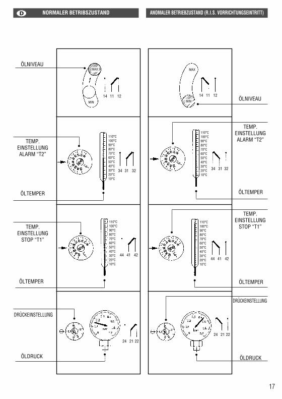
EINBAUANWEISUNGEN NORMALER BETRIBSZUSTAND ANOMALER BETRIEBZUSTAND (R.I.S. VORRICHTUNGSEINTRITT)
ÖLNIVEAU
TEMP. EINSTELLUNGALARM “T2”
ÖLTEMPER
TEMP. EINSTELLUNG
STOP “T1”
ÖLTEMPER
DRÜCKEINSTELLUNG
ÖLDRUCK
TEMP. EINSTELLUNGALARM “T2”
ÖLTEMPER
TEMP. EINSTELLUNG
STOP “T1”
ÖLTEMPER
ÖLDRUCK
ÖLNIVEAU
DRÜCKEINSTELLUNG
MAX
MIN
MAX
MIN14 11 12 14 11 12
34 31 32 34 31 32
44 41 4244 41 42
24 21 22
24 21 22
110°C100°C90°C80°C70°C60°C50°C40°C30°C20°C10°C
110°C100°C90°C80°C70°C60°C50°C40°C30°C20°C10°C
110°C100°C90°C80°C70°C60°C50°C40°C30°C20°C10°C
110°C100°C90°C80°C70°C60°C50°C40°C30°C20°C10°C
N°4 GEWINDESTIFE BEI 90°ODER
N°3 GEWINDESTIFE BEI 120°
Ø 60 ±130
M8
Ø 97 ±2
DREHMOMENT 6-8 Nm
(12 Nm max)
SCHUTZKAPPE
VORDER MONTAGEENTFERMEN !
1
2
3
4
16 17
EINBAU IN DEN TRAFO-KASTEN
- Bohrung Ø 60 ± 1 im Kasten- Flachdichtung (mitgeliefert) - Befestigungsschellen - Edelstahl (4 Stk im Lieferumfang)- Flachscheiben UNI 6592 Ø 8,4 - Edelstahl (4 Stk im Lieferumfang)- Federring UNI 1751 Ø 8,4 - Edelstahl (4 Stk im Lieferumfang)- M8 Mutter - UNI 5588 - Edelstahl (4 Stk im Lieferumfang)Mutterschrauben Position1,2,3,4 mit Drehmoment 3÷4 Nm Kreuzweise anziehen; die Operation in der gleichenReihenfolge wiederholen, bis das gewünsche Wert erreicht wird. Beim Aufheben des Transformators könnte, aufgrundder Deckelverformung, eine Oelverlust möglich sein. Es wird empfohlen Deckel mit geeigneter Staerke zu verwenden (min. 6-8 mm).
EINBAUANWEISUNGEN NORMALER BETRIBSZUSTAND ANOMALER BETRIEBZUSTAND (R.I.S. VORRICHTUNGSEINTRITT)
ÖLNIVEAU
TEMP. EINSTELLUNGALARM “T2”
ÖLTEMPER
TEMP. EINSTELLUNG
STOP “T1”
ÖLTEMPER
DRÜCKEINSTELLUNG
ÖLDRUCK
TEMP. EINSTELLUNGALARM “T2”
ÖLTEMPER
TEMP. EINSTELLUNG
STOP “T1”
ÖLTEMPER
ÖLDRUCK
ÖLNIVEAU
DRÜCKEINSTELLUNG
MAX
MIN
MAX
MIN14 11 12 14 11 12
34 31 32 34 31 32
44 41 4244 41 42
24 21 22
24 21 22
110°C100°C90°C80°C70°C60°C50°C40°C30°C20°C10°C
110°C100°C90°C80°C70°C60°C50°C40°C30°C20°C10°C
110°C100°C90°C80°C70°C60°C50°C40°C30°C20°C10°C
110°C100°C90°C80°C70°C60°C50°C40°C30°C20°C10°C
N°4 GEWINDESTIFE BEI 90°ODER
N°3 GEWINDESTIFE BEI 120°
Ø 60 ±1
30
M8
Ø 97 ±2
DREHMOMENT 6-8 Nm
(12 Nm max)
SCHUTZKAPPE
VORDER MONTAGEENTFERMEN !
1
2
3
4
16 17

BEMERKUNGEN ZUR MONTAGE UND VERWENDUNG DER R.I.S.- VORRICHTUNG
- Vor der Vorrichtungsmontage, Schutzkappe aus der Öffnung des Ölabflusses entfernen.- Für eine dauerhafte einwandfreie Vorrichtungslebensdauer dürfen keine sichtbaren Verformungen,
Schweißpunktspuren oder Grat auf der Auflagenfläche der R.I.S.-Vorrichtung auftreten.- Für eine bessere Festigkeit ist die Verwendung von 4 Gewindestiften empfehlbar.- RIS-Vorrichtung während des Kastenanstreichens zudecken. - Einbau der RIS-Vorrichtung erst nach Abtrockungsbehandlung des Trafos.- Vor jeweiligem Arbeitsablauf an der Vorrichtung ist die Spannung auszuschalten.- Instandhaltung und/oder Einstellung dürfen nur vom qualifizierten Personal durchgeführt werden. - COMEM SPA ist nicht für alle aus Montageanomalien, falschen Betätigungen oder ungeeigneten Verwendungen ent-
stehenden Beschädigungen verantwortlich.- Beim Wareneingang muß der Prüfzertifikat vorhanden sein .- 12 Monate Garantie- Die Vorrichtung darf nicht durch Lösungsmittel oder Benzin usw. gereinigt werden. Nur Trocken- oderWassernaßreinigungstuch verwenden.
ACHTUNG
- Der Gewindemuffe der R.I.S.- Vorrichtung darf nicht zum Einfüllen des Trafos verwendet werden. Nach derVorrichtungsmontage darf die Gewindemuffe nur für das Endeinfüllen der R.I.S.- Vorrichtung verwendet werden.
- Vorrichtung mit Öl einfüllen, bis sich der Schwimmer auf “MAX” stellt. Während dieses Arbeitsvorganges Entlüftungsventil offen lassen.
- Nach völligem Einfüllen ist der einwandfreie Schluß des Entlüftungventils und Einfüllstopfens nachzuprüfen. Beide sind von Hand zuzumanchen ohne Verwendung von Schlüsseln oder ähnlichen Geräten.
- Nach Einstellung vom roten Anzeiger des Thermometers, Schluß vom Schutzfenster sichern durch Zumachen von Hand und ohne Verwendung von Schlüsseln oder ähnlichen Geräten.
- Einwandfreie Befestigung des Klemmenkastenanschlusses Pg 21 nachprüfen. - Der eventuelle Anschluß an Ausdehnungsgefäß ist bei Raumtemperatur (≈ 23 °C) durchzuführen unter Einhaltung des
angegebenen Drehmoments (12 Nm max.)- Im Falle vom Anschluß an Ausdehnungsgefäß, ist der Anschluß an R.I.S. -Einrichtung durch Verwendung vom
Klebestoff “LOCTITE 542” durchzuführen.- Bei großer Schwankung vom Ölniveau oder höherer Gassteigerung als erwartet, hält sich der Schwimmer auf “MIN”
und schließt/öffnet einen elektrischen Stromkreis. Die Ergänzung des Trafos erfolgt durch Ölzusatz oder Entlüftungvom aufgespeicherten Gas. Der Schwimmer (RESET) darf wieder an die richtige Stelle gesetzt werden durchHinauftreiben des Magneten.
ANWIESUNGEN
Die abzuwickelnden Vorgänge sind wie folgt:A) Den Stopfen “2” entfernen das Ventil “3” mit entsprechendem Nippel auf Hahn “1” aufschrauben.B) Die Kappe “4” entfernen die Pumpe “5” mittels des hierfür vorgesehenen Gewindeanschlusses zuschalten und den
Hebel in Position OFF stellen.C) Die Pumpe ist bereits dafür ausgestattet. Unterdruck zu erzeugen.D)Zur Wiederherstellungen des Ölstands in der Vorrichtung R.I.S. den Hebel des Hahns “1” öffnen und die Pumpe “5”
ansaugen lassen. NAch diesem Vorgang der Hahn “1” schließen.E) Die Pumpe entlüften indem der Hebel auf Position ON gestellt wird.
Falls der erzielte Ölstand nicht ausreichend ist die Vorgänge “D” und “E” wiederholen.Nach Abschluß der Vorgänge die Komponenten “5” und “3” entfernen und die Vorrichtung wieder mit dem Stopfen “2”verschließen.
ANWEISUNGEN ZUR WIEDERHERSTELLUNG DES ÖLSTANDS VORRICHTUNG R.I.S.
ANWEISUNGEN ZUR WIEDERHERSTELLUNG DES ÖLSTANDS VORRICHTUNG R.I.S.
VORBENMERKUNG
Das Auffüllen der Vorrichtung mit Öl darf nur vom Hersteller des Transformators und bei Umgebungstemperatur vorge-nommen werden. Bei Inbetriebnahme der Vorrichtung R.I.S. sicherstellen, daß bei diesem das öl vollständig aufgefülltwurde. Trotzdem kann aus verschiedenen Gruunden der Ölstand niedriger als der vorher festgelegte sein.- Wenn der Transformator aufgrund der Umgebungstemperatur oder seines Betriebs warm ist kann sich der
Innendruck erhöhen und ein sichtbares Abfallen des Ölstandes in der Kammer der Vorrichtung verursachen. Um demProblem abzuhelfen, ist es ausreichend, die Verplombung auf dem Hebel des Hahns 1 (siehe Schema) zu entfernenden Stopfen 2 nicht ganz vollständig abzuschrauben und dann den Hebel des Hahns 1 leicht zu drehen, woraufhineine Entlüftung und ein Ansteigen des Ölstandss bis zur vollständigen Auffüllung erfolgt. Nach diesem Vorgangsicherstellen, daß der Hahn 2 wieder geschlossen wird und die Vorrichtung von eventuell ausgetretenem Ol reinigen.
- Bei kaltem Transformator (aufgrund einer langen Nichtbenutzung und/oder unter der Umgebungstemperatur liegen-der Außentemperatur) kann im Innern des Transformators ein Unterdruck und dementsprechend ein auf derAußenkammer der Vorrichtung sichtbares Absinken des Ölstands entstehen. Dieses Probelm kann gelöst werdenindem eine eventuell vorhandene Verplombung auf Hahn 2 durch dessen Aufschrauben entfernt und mittels einesEinfülltrichters der Ölstand langsam wieder vollständig aufgefüllt wird wobei darauf geachtet werden muß nichtsüberfließen zu lassen. Die Vorrichtung mit dem Stopfen 6 verschließen ohne Zuhilfnahme vom Werkzeugen oderSchlüssen. Sobald der Ölstand in der Vorrichtung wiederhergestellt wurde, kann der Transformator in Betrieb genom-men werden.
Falls kein Öl zur Wiederauffüllung zur Verfügung steht liefert die Firma Comem ein Zubehör-Set mit Pumpe die bereitsdafür ausgestattet ist in der Vorrichtung einen Ünterdruck zu schaffen und somit den Ölstand wiederherzustellen.
18 19

PRESSION TEMPERATURE NIVEAU HUILE FORMATION GAZ
PRESSOSTATferme/ouvre un circuit à la
pression reglée de 100 à 500 mbar
THERMOMETREreprésentation visuelle de la
température directe de l’huile etmax. température atteinte
THERMOSTAT “T2”(alarme)
ferme/ouvre un circuit àl’atteinte de la températurereglée (de 30 °C à 120 °C)
THERMOSTAT “T1”(décrochage)
ferme/ouvre un circuit àl’atteinte de la températurereglée (de 30 °C à 120 °C)
INDICATEURdetecteur visuel delegère variation du
niveau huile
DETECTEURferme/ouvre un circuit lors del’atteinte de la quantité max.
gaz produite (170 cm3)
R.I.S. DETECTEUR INTEGRE DE SECURITE
DETECTEURDetecteur visuel de variationimportante du niveau huileavec fermeture/ouverture
d’un circuit électrique
DESCRIPTION FONCTIONS VALEUR DE ESSAI DE CONTROLEMESURE
max 170 cm3
100 ÷ 500 mbar
30 ÷ 120 °C
30 ÷ 120 °C
30 ÷ 160 °C
Ouvrir le couvercle arrière avecles deux mains, sans faire levierd’un seul côté. Ramenez à zerole bouton de réglage du ther-mostat d’alarme marqué “T2”(ALARM)
Ramenez à zero le bouton deréglage du thermostat d’alarmemarqué “T1” (STOP)
Dévisser le masque de protec-tion pour ramener à zerol’aiguille rouge.
PRESSION (Pressostat)Le dispositif mesure l’élévation de la pression intérieure du transformateur.La valeur de fonctionnement peut être reglée en fonctions des instructionsdonnées de la part du constructeur de transformateur.Au cas d’une élévation de pression supérieure à celle prévue du réglage dupressostat, le même ferme/ouvre un circuit d’alerte.
TEMPERATURE :THERMOSTAT “T2” (ALARME)
- Le dispositif mesure la température interne de l’huile du transformateur.- La valeur de fonctionnement peut être reglée en fonction des instructionsdonnées de la part du constructeur de transformateur.- Au cas d’élévation de température supérieure à celle prévue par le réglage duthermostat “T2”, le même ferme/ouvre un circuit d’alerte.
THERMOSTAT “T1” (STOP) Le dispositif mesure la température interne de l’huile du transformateur.- La valeur de fonctionnement peut être reglée en fonction des instructionsdonnées de la part du constructeur de transformateur.- Au cas d’élévation de température supérieure à celle prévue par le réglage duthermostat “T1”, le même ferme/ouvre un circuit de stop.
THERMOMETRE- Le dispositif mesure la température interne de l’huile du transformateur visua-lisée à l’extérieur du dispositif grâce à un masque de protection.Le thermomètre est muni d’une aiguille rouge pouvant se ramener à zero.
NIVEAU HUILE (flotteur):Le dispositif mesure toute formation de gaz ou variation du niveau huile.- Au cas de petites variations de niveau d’ huile ou formation de gaz peu impor-tantes, le flotteur se placera entre “MIN et MAX” indiquués sur l’écran.- Au cas de variations importantes du niveau huile ou formation de gaz superiéu-re au prévue, le flotteur se placera sur “MIN” en fermant/ouvriant un circuitd’alerte.- Le gaz accumulé sera purgé/prélèvé d’un robinet approprié.
Approcher un aimant permanentau flotteur (entre les inscriptionsMIN e MAX) et le trainer vers lebas jusqu’à ce que il se position-ne sur l’inscription MIN. En vuede remettre le flotteur dans lajuste position, il est nécessarie dele mener en haut et détacherl’aimant.
Avec une pression inteme mini-mum du transformateur d’aumoins 100 mbars, amenez lebouton de réglage du pressostatsur le minimum.
DEGREE DE PROTECTION ( CEI - EN 60529) (CEI - EN 60529) IP 66
DEGREE DE TENUE AUX CHOCS (EN 50102) IK 07
TENUE AU BROUILLARD SALIN 1000 h
RESISTANCE AUX RAYONS UV (UNI-ISO 4892 / UNI-ISO 4582) 500 h
TENUE A LA TEMPERATURE -40 °C ÷ +120 °C
CONNEXION PRESSE-CABLE (FIL Ø 13 mm JUSQU’A Ø 18 mm) Pg 21
BOITE A BORNES (EN 50005 / EN 60947-7-1 / IEC 947-7-1) SUIVANT NORME
SECTION DU FIL A UTILISER SUR LES BORNES JUSQU’A 2,5 mm2
PRESSION MAX. D’EXERCISE 500 mbar
CARACTERISTIQUES ELECTRIQUES ENVELOPP
ISOLE
CARACTERISTIQUES GENERALES
TENSION A.C. D.C.Type de circuit OHM INDUCTIF OHM INDUCTIF
(cos ϕϕ >> 0,5) (L/R < 40 ms)Voltage 220 127 24 220 127 24 127 48 24 127 48 24
Puissance interruption des contacts 2A 2A 2A 2A 2A 2A 2A 2A 2A 2A 2A 2ANIVEAU HUILE/PRELEVEMENT GAZ
Puissance interruption des contacts 6A 6A 6A 1,5A 1,5A 1,5A 0,6A 0,6A 0,6A 0,6A 0,6A 0,6APRESSOSTAT
Puissance interruption des contacts 16A 16A 16A 4A 4A 4A 0,6A 0,6A 0,6A 0,6A 0,6A 0,6ATHERMOSTATS
20 21
PRÉCISION DES INSTRUMENTSTHERMOSTATS PRESSOSTATS THERMOMÈTRES
±3% sur le valeur de fond échelle ±10% sur le valeur de fond échelle ±3% sur le valeur de fond échelle
SCHEMA ELECTRIQUE (SUIVANT NORME EN 50005)
TEMP.DECLECHEMENT
“T1”
TEMP.ALARME
“T2”
PRESSION NIVEAUHUILE

APPLICATION SUR CAISSON TRANSFORMATEUR
- Trou Ø 60 ± 1 sur caisson- Joint plat (livré avec l’appareil)- Pattes de fixation inox (4 pièces livrées en sachet plastique)- Rondelles planes inox UNI 6592 Ø 8,4 (4 pièces livrées en sachet plastique)- Rondelles elastiques inox UNI 1751 Ø 8,4 (4 pièces livrées en sachet plastique)- Ecrous M8 inox UNI 5588 (4 pièces livrées en sachet plastique)Serrer les écrous en position 1,2,3,4 avec un couple de 3÷4 Nm de façon croisée; répéter l’opération suivant la mêmeséquence jusqu’à atteindre la valeur conseillée.Pendant le soulèvement du transformateur, à cause de la déformation du couvercle, une perte d’huile pourrait être pos-sible. Il est conseillé d’utiliser des couvercles avec épaissuer approprié (min. 6-8 mm).
INSTRUCTION DE MONTAGE
N°4 EMBOUTS FILETÉS À 90°OU
N°3 EMBOUTS FILETÉS À 120°
Ø 60 ±130
M8
Ø 97 ±2
COUPLE DE SERRAGE 6-8 Nm
(12 Nm max)
BOUCHON DE PROTECTION
ENLEVER AVANTLE MONTAGE !
1
2
3
4
CONDITIONS D’ANOMALIES (INTERVENTION DU R.I.S.)CONDITIONS NORMALES DE FONCTIONNEMENT
NIVEAU HUILE
REGLAGE TEMP.ALARM “T2”
TEMPERATUREHUILE
REGLAGE TEMP.STOP “T1”
TEMPERATUREHUILE
REGLAGE PRESSION
PRESSION HUILE
REGLAGETEMP.
ALARM “T2”
TEMPERATUREHUILE
REGLAGETEMP. STOP
“T1”
TEMPERATUREHUILE
PRESSIONHUILE
NIVEAU HUILE
REGLAGE PRESSION
MAX
MIN
MAX
MIN14 11 12 14 11 12
34 31 32 34 31 32
44 41 4244 41 42
24 21 22
24 21 22
110°C100°C90°C80°C70°C60°C50°C40°C30°C20°C10°C
110°C100°C90°C80°C70°C60°C50°C40°C30°C20°C10°C
110°C100°C90°C80°C70°C60°C50°C40°C30°C20°C10°C
110°C100°C90°C80°C70°C60°C50°C40°C30°C20°C10°C
22 23

APPLICATION SUR CAISSON TRANSFORMATEUR
- Trou Ø 60 ± 1 sur caisson- Joint plat (livré avec l’appareil)- Pattes de fixation inox (4 pièces livrées en sachet plastique)- Rondelles planes inox UNI 6592 Ø 8,4 (4 pièces livrées en sachet plastique)- Rondelles elastiques inox UNI 1751 Ø 8,4 (4 pièces livrées en sachet plastique)- Ecrous M8 inox UNI 5588 (4 pièces livrées en sachet plastique)Serrer les écrous en position 1,2,3,4 avec un couple de 3÷4 Nm de façon croisée; répéter l’opération suivant la mêmeséquence jusqu’à atteindre la valeur conseillée.Pendant le soulèvement du transformateur, à cause de la déformation du couvercle, une perte d’huile pourrait être pos-sible. Il est conseillé d’utiliser des couvercles avec épaissuer approprié (min. 6-8 mm).
INSTRUCTION DE MONTAGE
N°4 EMBOUTS FILETÉS À 90°OU
N°3 EMBOUTS FILETÉS À 120°
Ø 60 ±1
30
M8
Ø 97 ±2
COUPLE DE SERRAGE 6-8 Nm
(12 Nm max)
BOUCHON DE PROTECTION
ENLEVER AVANTLE MONTAGE !
1
2
3
4
CONDITIONS D’ANOMALIES (INTERVENTION DU R.I.S.)CONDITIONS NORMALES DE FONCTIONNEMENT
NIVEAU HUILE
REGLAGE TEMP.ALARM “T2”
TEMPERATUREHUILE
REGLAGE TEMP.STOP “T1”
TEMPERATUREHUILE
REGLAGE PRESSION
PRESSION HUILE
REGLAGETEMP.
ALARM “T2”
TEMPERATUREHUILE
REGLAGETEMP. STOP
“T1”
TEMPERATUREHUILE
PRESSIONHUILE
NIVEAU HUILE
REGLAGE PRESSION
MAX
MIN
MAX
MIN14 11 12 14 11 12
34 31 32 34 31 32
44 41 4244 41 42
24 21 22
24 21 22
110°C100°C90°C80°C70°C60°C50°C40°C30°C20°C10°C
110°C100°C90°C80°C70°C60°C50°C40°C30°C20°C10°C
110°C100°C90°C80°C70°C60°C50°C40°C30°C20°C10°C
110°C100°C90°C80°C70°C60°C50°C40°C30°C20°C10°C
22 23

- Avant le montage du dispositif enlevez le bouchon de protection du trou passage huile.- Pour assurer une très bonne tenue dans le temps, vérifiez soigneusement que le plan d’appui du dispositif R.I.S.ne présente aucune déformation importante, de traces évidentes de points de soudure ou bavures.
- Pour une meilleure tenue il est conseillé d’utiliser 4 embouts filetés.- Protegez le dispositif R.I.S. lors de la phase de peinture du caisson.- Installez le dispostif après le traitement de séchage du transformateur.- Avant toute intervention sur le dispositif, débranchez la tension.- Entretien et/ou réglage doit être effectué part du personnel qualifié.- La Société COMEM n’est pas responsable pour tout dommage dérivant d’anomalie de montage, fausse manutention
ou utilisation inadéquate.- A la reception de la marchandise, vérifiez la présence du certificat de controle .- Garantie 12 mois- Ne nettoyez pas le dispositif à l’aide de solvents, essence etc. Utilisez seulement un panneau sec ou humidifié d’eau.
REMARQUES IMPORTANTES
- N’utilisez pas le manchon fileté du R.I.S. pour le remplissage du transformateur, mais utilisez le manchon fileté seulement pour le remplissage final après installation du R.I.S.
- Remplissez d’huile le dispositif jusqu’à ce que le flotteur se place sur la position “MAX”.- Le remplissage terminé, vérifiez le serrage parfait du robinet purgeur et du bouchon de remplissage. Tous les deux
doivent être serrés manuellement sans l’utilisation de clés ou d’autres outils similaires.- Après le réglage de l’indicateur général du thermomètre, assurer le serrage du masque de protection manuellement
sans l’utilisation de clés ou d’autres outils similaires.- Vérifiez le bon et correcte serrage à tenue de la connection presse-câble Pg 21.- Le raccordement eventuel au conservateur doit être effectué à température ambiante (≈ 23 °C) en respectant le couple
de serrage spécifié (12 Nm max.).- Au cas de raccordement au conservateur, le raccordement au dispositif R.I.S. doit être effectué à l’aide d’une colle
type LOCTITE 542.- Au cas de variation importante du niveau huile ou formation de gaz supérieure au prévu, le flotteur se placera sur
l’inscription “MIN” en fermant/ouvrant un circuit électrique. Le rétablissement du transformateur doit être effectuéavec ajout d’hile ou en purgeant le gaz accumulé, et en remettant en position le flotteur (RESET) en le menant en hautà l’aide de un aimant.
AVERTISSEMENTS POUR LE MONTAGE ET L’UTILISATION DU DISPOSITIF R.I.S.
INSTRUCTIONS
Les opérations doivent être effectuées tie la fiçon suivante:A) Enlever ]c bouchon “2”, dévisser ]a valve “3”, ainsi que son raccord fileté du robinet “1”.B) Enlever le capuchon “4”, fixer la pompe “5” à I’aide de son raccord fileté spécial et tourner le levier en position OFF.C) La pompe est déjà réglée pour créerune dépression.D)Pour rétablir le niveau d’huile à l’intérieur du dispositif R.I.S., ouvrir le levier du robinet “1” et aspirer au moyen de la
pompe “5”. Après cette opération, placer le levier du robinet “1” en position fermée.E) Purger la pompe en tournant son levier en position ON.
Si le niveau d’huile atteint n’est toujours pas suffisant, répéter les operations “D” et “E”. Une fois les opérations terminées, enlever les pièces “5” et “3”, et refermer le dispositif à l’aide du bouchon “2”.
AVANT-PROPOS
Le remplissage d’huile du dispositif est effectué exclusivement par Ie constructeur du transformateur, à temperatureambiante ante. Au moment de la mise en service, s’assurer que le dispositif R.I.S. est complètement rempli d’huile.Toutefois, pour différentes raisons, le niveau d’huile ,peut être inférieur au niveau préetabli.- Si le transformateur est chaud, à cause d’une température ambiante élevée ou en raison de son fonctionnement, la
pression interne peut augmenter et provoquer une chute apparente du niveau d’huile de la chambre du dispositif.Pour remédier à cet inconvénient, il suffit d’enlever le plomb placé sur le levier du robinet 1 (voir schéma), de dévisserle bouchon 2 (mais pas complètement) et de tourner légèrement le levier du robinet 1, ce qui provoque ]a purge et lamontée du niveau d’huile, jusqu’au remplissage total. Après cette opération, prendre soin de bien refermer le bouchon2 et nettoyer le dispositif en éliminant éventuellement l’huile qui aurait ecoulé.
- Quand le transformateur est froid, à cause d’une longue période d’inactivité et/ou d’une température extérieure infé-rieure à la température ambiante, un phénomène de dépression peut se produire à l’intérieur du transformateur etentraîner une chute du niveau d’huile apparente dans a chambre externe du dispositif.Cet inconviénient peut être supprimé de ]a façon suivante: enlever le plomb sur le bouchon 2, dévisser ce dernier et, àl’aide d’un entonnoir, rétablir le niveau d’huile lentement jusqu’au remplissage total du dispositif, tout en faisant atten-tion à ne pas le faire déborder. Refermer le dispositif au moyen du bouchon 6, sans utiliser d’outils ou de clés. Unefois que le niveau d’huile du dispositif a été rétabli, le transformateur peut être mis en service.
Sil n’y a pas d’huile à disposition pour rétablir le niveau, Comem fournit tin ensemble d’accessoires avec pompe déjàréglée pour créer tine depression dans le dispositif, et done rétablir le niveau d’huile.
INSTRUCTIONS POUR LE RETABLISSEMENT DU NIVEAU D’HUILE SUR LE DISPODITIF R.I.S.
INSTRUCTIONS POUR LE RETABLISSEMENT DU NIVEAU D’HUILE SUR LE DISPODITIF R.I.S.
24 25

PRESION TEMPERATURA NIVEL DE ACEITE FORMACION DE GAS
PRESOSTATOAbre/cierra un circuito a la
presión regulada(entre 100 y 500 mbar)
TERMOMETRORepresentación visual de la
temperatura directa del aceitey de la temperatura máxima
alcanzada
TERMOSTATO “T2” (alarma)Cierra/abre un circuito en
cuanto se alcance la tempera-tura regulada (entre 30°C y
120°C)
SEÑALADORDetector visual de una varia-ción importante del nivel delaceite, con el cierre/abertura
de un circuito eléctrico.
TERMOSTATO “T1” (desen-ganche)
Cierra/abre un circuito encuanto se alcance la tempera-
tura regulada (entre 30°C y120°C)
INDICADORDetector visual de una ligeravariación del nivel del aceite
SEÑALADORCierra/abre un circuito en
cuanto se alcance la cantidadmáxima de gas producida
(170 cm3)
R.I.S. INTEGRIERTE SICHERHEITSABMEßVORRICHTUNG
DESCRIPCION DE LAS FUNCIONESVALOR DE
TEST DE COMPROBACIONMEDICION
max 170 cm3
100 ÷ 500mbar
30 ÷ 120 °C
30 ÷ 120 °C
30 ÷ 160 °C
Abrir la tapa trasera con ambasmanos sin apalancar, sólo en unlado. Colocar en “cero” el pomoregulador del termostato dealarma (ALARM) que está contramarcado “T2”.
Colocar en “cero” el pomo regu-lador del termostato de desen-ganche (STOP) marcado “T1”.
Desatornillar la portilla de pro-tección para poner otra vez acero el índice de temperaturamáxima.
PRESION (PRESOSTATO)El dispositivo detecta el aumento de la presión al interior del transformador.Puede regularse el valor de funcionamiento con arreglo a las instrucciones delconstructor del transformador.En caso de que haya un aumento de presión quesobrepase el valor establecido por la regulación del presostato, el mismo cier-ra/abre un circuito de alarma.
TEMPERATURA:TERMOSTATO “T2” (ALARMA)
El dispositivo detecta la temperatura del aceite al interior del transformador.Puede regularse el valor de funcionamiento con arreglo a las instrucciones delconstructor del transformador. En caso de que el aumento de la temperaturasobrepase el valor establecido por la regulación del termostato “T2”, el mismocierra/abre un circuito de alarma.
TERMOSTATO “T1” (DESENGANCHE/STOP)El dispositivo detecta la temperatura del aceite al interior del transformador.Puede regularse el valor de funcionamiento con arreglo a las instrucciones delconstructor del transformador. En caso de que el aumento de la temperaturasobrepase el valor establecido por la regulación del termostato “T1”, el mismocierra/abre un circuito de desenganche.
TERMOMETROEl dispositivo detecta la temperatura del aceite al interior del transformador, quees visualizada al exterior del dispositivo a través de la portilla de protección.El termómetro está equipado de un índice de temperatura máxima que puedeponerse otra vez a cero.
NIVEL DEL ACEITE (Flotador):El dispositivo detecta la formación de gas o la variación del nivel del aceite.-En caso de que haya pequeñas variaciones del nivel del aceite o formación no muy grande de gas, el flotador se colocará entre los letreros “MIN” y “MAX” que aparecen en la pantalla.-En caso de que haya una variación importante del nivel del aceite o formación de gas en cantidad mayor de lo que está previsto, el flotador se colocará en el letrero “MIN” cerrando/abriendo un circuito de alarma.-El gas que se ha acumulado se deja escapar/se toma a través del grifo al efecto.
Acercar un imán permanente alflotador (entre los letreros MIN yMAX) y arrastrarlo hacia abajohasta alcanzar el letrero MIN.Para restablecer la posición cor-recta del flotador hace falta arra-strarlo hacia arriba y desconec-tar el imán.
Habiendo por lo menos una pre-sión mínima de 100 mbar alinterior del transformador, colo-car en el mínimo el pomo regu-lador del termostato.
GRADO DE PROTECCION (CEI-EN 60529) IP 66
GRADO DE RESISTENCIA A LOS CHOQUES (EN 50102) IK 07
RESISTENCIA A LA NIEBLA SALINA 1000h
RESISTENCIA A LOS RAYOS ULTRAVIOLETAS (UNI-ISO 4892 / UNI-ISO 4582) 500h
TRESISTENCIA A LA TEMPERATURA: -40°C ÷ +120°C
CONEXION ABRAZADERA PARA CABLES (HILO Ø13 mm. HASTA 18 mm) Pg 21
CAJA DE BORNES (EN 50005/EN 60947-7-1 / IEC 947-7-1) CON ARREGLO A LAREGLAMENTACION VIGENTE
SECCION DEL HILO QUE HAY QUE EMPLEAR EN LA CAJA DE BORNES: HASTA 2,5 mm2
PRESION MAXIMA DE TRABAJO: 500 mbar
CARACTERISTICAS ELECTRICAS INVOLUCRO AISLADO
CARACTERISTICAS GENERALES
CORRIENTE A.C. D.C
Tipo de circuito: OHMICO INDUCTIVO OHM ICOINDUCTIVO(cos ϕϕ >> 0,5) (L/R < 40 ms)
VOLTAJE 220 127 24 220 127 24 127 48 24 127 48 24Poder de interrupción de los contactos 2A 2A 2A 2A 2A 2A 2A 2A 2A 2A 2A 2ANIVEL DEL ACEITE / ACUMULACION GASPoder de interrupción de los contactos 6A 6A 6A 1,5A 1,5A 1,5A 0,6A 0,6A 0,6A 0,6A 0,6A 0,6A
PRESOSTATOPoder de interrupción de los contactos 16A 16A 16A 4A 4A 4A 0,6A 0,6A 0,6A 0,6A 0,6A 0,6A
TERMOSTATOS
26 27
PRECISIÓN INSTRUMENTOSTERMOSTATOS INDICADORES DE PRESIÓN TERMÓMETROS
±3% del valor de fondo escala ±10% del valor de fondo escala ±3% del valor de fondo escala
DIAGRAMA DE CONEXIONES CON ARREGLO A LA NORMA EN 50005
TEMP.DESCONEXION
“T1”
TEMP.ALARMA
“T2”
PRESION NIVEL DELACEITE

APLICACION EN LA CAJA DEL TRANSFORMADOR
- Agujero Ø 60 ± 1 en la caja- Empaque plano (se suministra en dotación)- Estribos de bloqueo en acero inox (cantidad 4 piezas, suministradas en dotación)- Arandelas planas UNI 6592 Ø 8,4 en acero inox (cantidad 4 piezas, suministradas en dotación)- Arandelas elásticas UNI 1751 Ø 8,4 en acero inox (cantidad 4 piezas, suministradas en dotación)- Tuercas M8 UNI 5588 en acero inox (cantidad 4 piezas, suministradas en dotación)Aprietar las tuercas en posición1,2,3,4 con par de 3÷4 Nm de manera cruzada; repetir la operacón con la mismasecuencia hasta el valor aconseillado.Durante el levantamiento del transformador podría ocurrir un goteo de aceite como consecuencia de la deformación dela tapa. Se aconseja emplear tapas que tengan un espesor adecuado (6-8 mm. mínimo).
INSTRUCCIONES PARA EL MONTAJE
NIVEL DEL ACEITE
PREPARACIONTEMPERATURA
ALARM “T2”
TEMPERATURAOLIO
PREPARACIONTEMPERATURA
STOP “T1”
TEMPERATURAOLIO
PREPARACIONPRESION
PRESION OLIO
PREPARACIONTEMPERATURA
ALARM “T2”
TEMPERATURAOLIO
PREPARACIONTEMPERATURA
STOP “T1”
TEMPERATURAOLIO
PRESSION OLIO
NIVEL DELACEITE
PREPARACIONPRESION
MAX
MIN
MAX
MIN14 11 12 14 11 12
34 31 32 34 31 32
44 41 4244 41 42
24 21 22
24 21 22
110°C100°C90°C80°C70°C60°C50°C40°C30°C20°C10°C
110°C100°C90°C80°C70°C60°C50°C40°C30°C20°C10°C
110°C100°C90°C80°C70°C60°C50°C40°C30°C20°C10°C
110°C100°C90°C80°C70°C60°C50°C40°C30°C20°C10°C
CONDICIONES ANOMALE (INTERVERCIÒN DE R.I.S.)CONDICCIONES NORMALES DE FUNCIONAMENTO
N°4 PRISIONEROS A 90°OU
N°3 PRISIONEROS A 120°
Ø 60 ±130
M8
Ø 97 ±2
PAR DE APRIETAMENTO 6-8 Nm
(12 Nm max)
TAPON DE PROTECCION
QUITAR ANTES DE INSTALAR
1
2
3
4
28 29

APLICACION EN LA CAJA DEL TRANSFORMADOR
- Agujero Ø 60 ± 1 en la caja- Empaque plano (se suministra en dotación)- Estribos de bloqueo en acero inox (cantidad 4 piezas, suministradas en dotación)- Arandelas planas UNI 6592 Ø 8,4 en acero inox (cantidad 4 piezas, suministradas en dotación)- Arandelas elásticas UNI 1751 Ø 8,4 en acero inox (cantidad 4 piezas, suministradas en dotación)- Tuercas M8 UNI 5588 en acero inox (cantidad 4 piezas, suministradas en dotación)Aprietar las tuercas en posición1,2,3,4 con par de 3÷4 Nm de manera cruzada; repetir la operacón con la mismasecuencia hasta el valor aconseillado.Durante el levantamiento del transformador podría ocurrir un goteo de aceite como consecuencia de la deformación dela tapa. Se aconseja emplear tapas que tengan un espesor adecuado (6-8 mm. mínimo).
INSTRUCCIONES PARA EL MONTAJE
NIVEL DEL ACEITE
PREPARACIONTEMPERATURA
ALARM “T2”
TEMPERATURAOLIO
PREPARACIONTEMPERATURA
STOP “T1”
TEMPERATURAOLIO
PREPARACIONPRESION
PRESION OLIO
PREPARACIONTEMPERATURA
ALARM “T2”
TEMPERATURAOLIO
PREPARACIONTEMPERATURA
STOP “T1”
TEMPERATURAOLIO
PRESSION OLIO
NIVEL DELACEITE
PREPARACIONPRESION
MAX
MIN
MAX
MIN14 11 12 14 11 12
34 31 32 34 31 32
44 41 4244 41 42
24 21 22
24 21 22
110°C100°C90°C80°C70°C60°C50°C40°C30°C20°C10°C
110°C100°C90°C80°C70°C60°C50°C40°C30°C20°C10°C
110°C100°C90°C80°C70°C60°C50°C40°C30°C20°C10°C
110°C100°C90°C80°C70°C60°C50°C40°C30°C20°C10°C
CONDICIONES ANOMALE (INTERVERCIÒN DE R.I.S.)CONDICCIONES NORMALES DE FUNCIONAMENTO
N°4 PRISIONEROS A 90°OU
N°3 PRISIONEROS A 120°
Ø 60 ±1
30
M8
Ø 97 ±2
PAR DE APRIETAMENTO 6-8 Nm
(12 Nm max)
TAPON DE PROTECCION
QUITAR ANTES DE INSTALAR
1
2
3
4
28 29
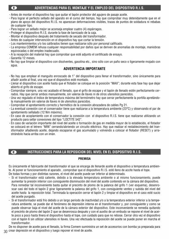
ADVERTENCIAS PARA EL MONTAJE Y EL EMPLEO DEL DISPOSITIVO R.I.S.
- Antes de montar el dispositivo hay que quitar el tapón protector del agujero de pasaje aceite.- Para lograr el perfecto sellado del aparato en el curso del tiempo, hay que comprobar muy detenidamente que en el
plano de apoyo del dispositivo R.I.S. no aparezcan deformaciones visibles, trazas de puntos de soldadura ni rebabasde cualquier tipo.
- Para lograr un sellado mejor se aconseja emplear cuatro (4) espárragos.- Proteger el dispositivo R.I.S. durante la fase de barnizado de la caja.- Montar el dispositivo después del tratamiento de secado del transformador.- Antes de cualquier intervención en el dispositivo hay que cortar la tensión.- Los mantenimientos y/o los calibrados tienen que realizarse sólo por personal calificado.- La empresa COMEM rehusa cualquier responsabilidad por daños que se deriven de anomalías de montaje, maniobras
equivocadas o del empleo inadecuado.- A la recepción del material hay que comprobar que esté adjunto el certificado de ensayo.- Garantía 12 meses.- No hay que limpiar el dispositivo con disolventes, gasolina etc., sino sólo con un paño seco o ligeramente mojado con
agua.ADVERTENCIA IMPORTANTE
- No hay que emplear el manguito enroscado de 1” del dispositivo para llenar el transformador, sino únicamente paraañadir aceite al final, una vez que el dispositivo esté montado.
- Llenar el dispositivo con aceite hasta que el flotador se coloque en la posición “MAX”; durante esta fase hay que dejarabierto el grifo de escape.
- Comprobar siempre, una vez acabado el llenado, que el grifo de escape y el tapón de llenado estén perfectamente cer-rados. Hay que cerrar ambos manualmente, sin valerse de llaves ni de otros utensilios parecidos.
- Una vez regulado el índice de temperatura máxima del termómetro hay que cerrar perfectamente la portilla apretándo-la manualmente sin valerse de llaves ni de utensilios parecidos.
- Comprobar el apretamiento correcto y hermético de la conexión abrazadera de cables Pg 21.- La eventual conexión con el conservador tiene que realizarse a la temperatura ambiente (23°C) y observando el par de
apretamiento señalado (12 Nm máximo).- En caso de acoplamiento con el conservador la conexión con el dispositivo R.I.S. tiene que realizarse utilizando un
producto para sellar conexiones del tipo “LOCTITE 542”.- En caso de variación importante del nivel del aceite o formación de gas en medida mayor de lo establecido, el flotador
se colocará en el letrero “MIN” cerrando/abriendo un circuito eléctrico. Hay que realizar el restablecimiento del tran-sformador añadiendo aceite, dejando escaparse el gas acumulado y volviendo a colocar el flotador (RESET) y arra-strándolo hacia arriba con un imán.
INSTRUCCIONES
Las operaciones se realizan come indicado a continuación:A) Quitar el tapón “2” enroscar la válvula “3” con el relativo niple en el grifo “1”B) Sacar el capuchón “4” meter la bomba “5” mediante el acoplamiento roscando correspondiente y girar la palancahasta la posicion OFF.C) Ya ésta preparada la bomba para crear depresión.D) Para la reposición del nivel del aceite interno del R.I.S. abrir la palanca del grifo “1” y aspirar con la bomba “5”. Acontinuación cerrar la palanca del grifo “1”.E) Purgar la bomba girando girando la palanca hasta la posición ON.
Sie el nivel alcanzado no bastase, repetir las operaciones “D” y “E”.Al terminar las operaciones quitar los componentes “5” y “3” y cerrar el dispositivo con el tapón “2”.
INSTRUCCIONES PARA LA REPOSICION DEL NIVEL EN EL DISPOSITIVO R.I.S.
INSTRUCCIONES PARA LA REPOSICION DEL NIVEL EN EL DISPOSITIVO R.I.S.
PREMISA
Es únicamente el fabricante del transformador el que se encarga de llenarde aceite el dispositivo a temperatura ambien-te. Al poner er funcionamiento el aparado , comprobar que el dispositivo R.I.S. esté lleno de accite hasta el tope.De todas formas y por distintas razones, el nivel del aceite puede ser inferior al determinado.- Si el transformador está caliente, debido a la elevada temperatura ambiente o al mismo funcionamiento, puede
aumentar la presión interior con consiguiente disminución del nivel del aceite contenido en la cámara del dispositivo. Para remediar tal inconveniente basta quitar el precinto de plomo de la palanca del grifo 1 (ver esquema), desenro-scar casi del todo el tapón 2 girar ligeramente la palanca del grifo 1, con consiguiente venteo y subida del nivel delaceite hasta la reposición total. Terminada la operación cerrar el tapón 2 y limpiar el dispositivo en el caso esté suciodel aceite purgado.
- Si el transformador está frio debido a un largo periodo de inactividad y/o a la temperatura exterior inferior a la tempe-ratura ambiente, se puede dar el fenómeno de depresión interna en el transformador y, por consiguiente y como sepuede observar baja el nivel del aceite de la cámara exterior del dispositivo. Este inconveniente se remedia quitandoel precinto de plomo del tapón 2 que se desenrosca después y con el auxilio de un embudo se repone el nivel de acei-te poco a poco hasta llnera el dispositivo hasta el tope, con cuidado para que no rebose. Cerrar otra vez el dispositivocon el tapón 6 sin utilizar utensilios ni llaves. Una vez efectuada la reposición del aceite se puede poner en marcha eltransformador.
De no disponer de aceite para el llenado, la firma Comem suministra un set de accesorios con bomba ya preparada paracrear depresión en el dispositivo y luego reponer el nivel de aceite. 30 31

PRESSACAVO Pg 21CABLE CONNECTION Pg 21KLEMMKASTEN ANSCHLUß Pg21PRESSE-CABLE Pg 21ABRAZADERA PARA CABLE Pg21
fig. / Abb. 1
MANICOTTO DI RIEMPIMENTO OLIO DISPOSITIVO R.I.S.R.I.S. DEVICE OIL FILLER SLEEVEÖLEINFÜLLSTOPFEN R.I.S.-VORRICHTUNGMANCHON REMPLISSAGE HUILE DISPOSITIF R.I.S.MANGUITO DE LLENADO CON ACEITE DEL DISPOSITIVO R.I.S.
MAGNETE PER TEST DI VERIFICA (SU RICHIESTA)MAGNET FOR CHECKING TEST (ON REQUEST)MAGNET FÜR CHECK-PRÜFUNG (AUF WUNSCH)AIMANT POUR ESSAI DE CONTROLE (SUR DEMANDE)IMAN PARA TEST DE COMPROBACION (A PETICION)
SU RICHIESTAON REQUEST
AUF WUNSCHSUR DEMANDE
A PETICIONVALVOLA
DI VENTILAZIONE VENTILATION
VALVE SOUPAPE DEVENTILATION
LÜFTUNGSVENTILVALVULA DE VENTILACION
RUBINETTO SFIATO-PRELIEVO GAS G 1/8GAS LEAK/DRAW VALVE G 1/8GAS ENTLÜFTUNGS/ENTNAHMEVENTIL G 1/8ROBINET PURGE/PRELEVEMENT GAZ G1/8GRIFO DE EXPULSION - TOMA DE GAS G 1/8
PART. “X”: FORI PER SIGILLATURA-PIOMBATURAPART. “X”: SEALING HOLESDETAIL “X”: BOHRUNGEN FÜR VERSIEGLUNG/PLOMBIERUNGDETAIL “X”: TROUS POUR SCELLAGE/PLOMBAGEDETALLE “X”:AGUJEROS PARA SELLADO-EMPLOMADURA
290
240
52
100
11616030
12,5Ø 22
Ø 85 67
32 33

NOTES NOTES
34 35

NOTES NOTES
34 35

R.I.S.®Integrated Safety Detector
R.I.S.®Integrierte Sicherheitsabmeßvorrichtung
R.I.S.®Détecteur Intègre de Sécurité
R.I.S.®Detector Integrado de Seguridad
R.I.S.®Rilevatore Integrato di Sicurezza
1 9 9 9
comem ® S.p.A. Strada Statale 11, Signolo 22
36054 MONTEBELLO VIC. NO (VI)Tel. 0444 449311 - Fax 0444 449352 - 440359
http://www.comem.com • e-mail:[email protected] Edig
raf s
rl - E
dizi
one
03/0
7 - C
odic
e 54
100D
2001
®


