Detection of Unbalance in Rotating Machines Using Shaft Deflection Measurement during Its Operation
13
IOSR Journal of Mechanical and Civil Engineering (IOSR-JMCE) ISSN: 2278-1684 Volume 3, Issue 3 (Sep-Oct. 2012), PP 08-20 www.iosrjournals.org www.iosrjournals.org 8 | Page Detection of Unbalance in Rotating Machines Using Shaft Deflection Measurement during Its Operation Md. Abdul Saleem 1 , G. Diwakar 2 , Dr. M.R.S. Satyanarayana 3 1 M.Tech Student, 2 Assoc. Professor, Mech. Engg. Dept, Prasad V. Potluri Siddhartha Institute of Technology, Kanuru, Vijayawada, Andhra Pradesh, India-520007. 3 Vice Principal, Mech. Engg. Dept, Gitam University, Visakhapatnam, Andhra Pradesh, India. Abstract: Vibrations are found almost everywhere in rotating machines. Vibrations in rotating machinery are commonly the result of mechanical faults including mass unbalance, coupling misalignment, mechanical looseness, and many other causes. Unbalance is the most cause of machine vibration, an unbalanced rotor always cause more vibration and generates excessive force in the bearing area and reduces the life of the machine. In this paper ‘Deflected Shape of Shaft’ (DSS) of a rotating machine was found for detecting unbalance in its rotating components. The change in deflection shape gives the presence of unbalance in the shaft. Experiment reveals that a significant change in the DSS as an early warning indicator of unbalance in the rotating components. Tests were performed on a machinery fault simulator under various conditions of unbalance. Vibration data in terms of displacement was simultaneously acquired using a FFT (Fast Fourier Transform). The rotor shaft displacements were measured at different speeds using FFT at both unbalanced and balanced condition. The experimental frequency spectra were taken for both balanced and unbalanced condition. The presence of unbalance produces a change in the DSS at the rotor running speed and this data was extracted by conducting the experiments. A comparison was then performed with the theoretical calculation and also the vibration data acquired from FFT, at different running speeds. The results of this work provide a new method for detecting machinery unbalance, and offer a simplified approach for on-line fault detection in operating machinery. Keywords: Unbalance, Vibration, Deflected Shape of Shaft (DSS), Fast Fourier Transform (FFT) Nomenclature: MNDE: Motor Non Drive End; H: Horizontal; D: Displacement MDE: Motor Drive End; V: Vertical; Theo: Theoretical PBE: Pillow Block End; A: Axial Exp: Experimental I. Introduction Rotor unbalance is the most common reason in machine vibrations. Most of the rotating machinery problem can be solved by using the rotor balancing and misalignment. Mass unbalance in a rotating system often produces excessive synchronous forces that reduce the life span of various mechanical elements. A very small amount of unbalance may cause severe problem in high speed rotating machines. Overhung rotors are used in many engineering applications like pump, fans, propellers and turbo machinery. The vibration signature of the overhung rotor is totally different from the center hung rotors. The vibration caused by unbalance may destroy critical parts of the machine, such as bearings, seals, gears and couplings. Rotor unbalance is a condition in which the centre of mass of a rotating assembly, typically the shaft and its fixed components like disks and blades etc. is not coincident with the centre of rotation. In practice, rotors can never be perfectly balanced because of manufacturing errors such as porosity in casting, non-uniform density of material, manufacturing tolerances and gain or loss of material during operation. As a result of mass unbalance, a centrifugal force is generated and must be reacted against by bearing and support structures. Surendra N. Ganeriwala et al. [1] has demonstrated the use of the operational deflection shape (ODS) of a rotating machine as a means of detecting unbalance in its rotating components. The results of this work provide a new method for detecting machinery unbalance and offer a simplified approach for on-line fault detection in operating machinery. Zhunag li et al. [2] has demonstrated the effects of rotating machinery shaft misalignment on its dynamic behavior which is characterized in the form of an Operational Deflection Shape (ODS). In this approach, an ODS derived from multiple accelerometer signals acquired at various points on the machine is used to diagnose shaft misalignment. Tests are performed on a machinery fault simulator under various operating conditions. Operating data is simultaneously acquired using a multi-channel data acquisition system. William W. Clark et al. [3] has used technique for measuring and actively controlling dynamic bearing loads in rotating machinery subject to periodic excitations. Bearing loads are estimated using the Deflection-
-
Upload
iosr-journals -
Category
Documents
-
view
250 -
download
7
description
http://www.iosrjournals.org/iosr-jmce/papers/vol3-issue3/B0330820.pdf
Transcript of Detection of Unbalance in Rotating Machines Using Shaft Deflection Measurement during Its Operation
IOSR Journal of Mechanical and Civil Engineering (IOSR-JMCE)
ISSN: 2278-1684 Volume 3, Issue 3 (Sep-Oct. 2012), PP 08-20 www.iosrjournals.org
www.iosrjournals.org 8 | Page
Detection of Unbalance in Rotating Machines Using Shaft
Deflection Measurement during Its Operation
Md. Abdul Saleem1, G. Diwakar
2, Dr. M.R.S. Satyanarayana
3
1M.Tech Student,
2Assoc. Professor, Mech. Engg. Dept, Prasad V. Potluri Siddhartha Institute of Technology,
Kanuru, Vijayawada, Andhra Pradesh, India-520007. 3Vice Principal, Mech. Engg. Dept, Gitam University, Visakhapatnam, Andhra Pradesh, India.
Abstract: Vibrations are found almost everywhere in rotating machines. Vibrations in rotating machinery are
commonly the result of mechanical faults including mass unbalance, coupling misalignment, mechanical
looseness, and many other causes. Unbalance is the most cause of machine vibration, an unbalanced rotor
always cause more vibration and generates excessive force in the bearing area and reduces the life of the
machine. In this paper ‘Deflected Shape of Shaft’ (DSS) of a rotating machine was found for detecting
unbalance in its rotating components. The change in deflection shape gives the presence of unbalance in the shaft. Experiment reveals that a significant change in the DSS as an early warning indicator of unbalance in the
rotating components. Tests were performed on a machinery fault simulator under various conditions of
unbalance. Vibration data in terms of displacement was simultaneously acquired using a FFT (Fast Fourier
Transform). The rotor shaft displacements were measured at different speeds using FFT at both unbalanced and
balanced condition. The experimental frequency spectra were taken for both balanced and unbalanced
condition. The presence of unbalance produces a change in the DSS at the rotor running speed and this data
was extracted by conducting the experiments. A comparison was then performed with the theoretical calculation
and also the vibration data acquired from FFT, at different running speeds. The results of this work provide a
new method for detecting machinery unbalance, and offer a simplified approach for on-line fault detection in
operating machinery.
Keywords: Unbalance, Vibration, Deflected Shape of Shaft (DSS), Fast Fourier Transform (FFT)
Nomenclature: MNDE: Motor Non Drive End; H: Horizontal; D: Displacement
MDE: Motor Drive End; V: Vertical; Theo: Theoretical
PBE: Pillow Block End; A: Axial Exp: Experimental
I. Introduction Rotor unbalance is the most common reason in machine vibrations. Most of the rotating machinery problem can be solved by using the rotor balancing and misalignment. Mass unbalance in a rotating system
often produces excessive synchronous forces that reduce the life span of various mechanical elements. A very
small amount of unbalance may cause severe problem in high speed rotating machines. Overhung rotors are
used in many engineering applications like pump, fans, propellers and turbo machinery. The vibration signature
of the overhung rotor is totally different from the center hung rotors. The vibration caused by unbalance may
destroy critical parts of the machine, such as bearings, seals, gears and couplings. Rotor unbalance is a condition
in which the centre of mass of a rotating assembly, typically the shaft and its fixed components like disks and
blades etc. is not coincident with the centre of rotation. In practice, rotors can never be perfectly balanced
because of manufacturing errors such as porosity in casting, non-uniform density of material, manufacturing
tolerances and gain or loss of material during operation. As a result of mass unbalance, a centrifugal force is
generated and must be reacted against by bearing and support structures.
Surendra N. Ganeriwala et al. [1] has demonstrated the use of the operational deflection shape (ODS) of a rotating machine as a means of detecting unbalance in its rotating components. The results of this work
provide a new method for detecting machinery unbalance and offer a simplified approach for on-line fault
detection in operating machinery.
Zhunag li et al. [2] has demonstrated the effects of rotating machinery shaft misalignment on its
dynamic behavior which is characterized in the form of an Operational Deflection Shape (ODS). In this
approach, an ODS derived from multiple accelerometer signals acquired at various points on the machine is
used to diagnose shaft misalignment. Tests are performed on a machinery fault simulator under various
operating conditions. Operating data is simultaneously acquired using a multi-channel data acquisition system.
William W. Clark et al. [3] has used technique for measuring and actively controlling dynamic bearing
loads in rotating machinery subject to periodic excitations. Bearing loads are estimated using the Deflection-
Detection of Unbalance in Rotating Machines Using Shaft Deflection Measurement during Its
www.iosrjournals.org 9 | Page
Coefficient Method, a technique which does not rely on a full system model, and which applies commonly-used
shaft-deflection measurement equipment to obtain estimates of bearing loads.
Kevin Gatzwiller et al. [4] describes the concept and the basic technique of measuring torsional
operational deflection shapes using the Torsional Vibration Meter Type 2523, the Multichannel Analysis
System Type 3550 and the Operational Deflection Shapes Software WT 9380, running on a Personal Computer. Mark H. Richardson et al. [5] describes the mode shapes and operating "deflection" shapes are related
to one another. In fact, one is always measured in order to obtain the other. Yet, they are quite different from
one another in a number of ways. These articles discuss the relationships between modal testing, modal analysis
and operating deflection shape measurements.
Unfortunately, other common faults can also generate high levels of vibration at 1xRPM including
coupling misalignment, looseness, rotor bows, and a variety of other sources. In some cases, these faults will
produce other symptoms that can suggest corrections other than balancing should be done. Yet in many cases,
balancing may be the chosen course of action for lowering vibration amplitudes even though it is not the source
of vibration.
1.1 Unbalance and Vibration Unbalance occurs in a rotating machine when the mass centerline and the geometric center do not
coincide on each other. Unbalanced rotors generate vibration which may damage their components. In order to
extend the life of the machine, vibration due to unbalance must be reduced to acceptable level. Despite the
ability to reduce unbalance to low levels, these levels or limits must be defined.
Unbalance amount is expressed as:
U = m*r
Where, m = unbalance mass (in kg)
r = distance from unbalance mass to shaft/rotor centerline (in m)
The unbalance force generating the vibration is expressed as:
F = m*r*ω2
Where, F = force (N)
m = mass (kg)
r = radius (m)
ω= speed (rad/sec)
Unbalance Vibration = Unbalance Force/Dynamic Stiffness Fig 1.1 Centrifugal Force
There is no handy recognizable general relation between rotor unbalance and the machine vibrations.
The unbalance response depends essentially on speed, the geometric proportions and mass distribution of rotor,
as well as on the dynamic stiffness of the shaft, bearings and the foundation., For a particular rotor, unbalance vibration will have different values depending on its operating speed, type of bearings (e.g. fluid film or rolling
element), foundation etc. while the unbalance amount itself is constant and only related to the rotor. So, the
balancing quality limit should not be oversimplified and given through vibration readings only. This is
especially true for new machines for which no pervious vibration experience exists.
An unbalanced rotating machine can cause parts to wear out quickly, and account for a significant
percentage of a machine‟s downtime. Not only is downtime expensive in terms of lost production, but costs of
replacement parts, inventory, and energy consumption are also increased. Traditionally, vibration signatures
(level profiling of single point vibration spectra), and orbit plots have been the preferred tools for detecting and
diagnosing machinery unbalance. Although these tools may be effective when used by an expert, „Deflected
Shape of Shaft‟ (DSS) analysis offers a simpler, more straightforward approach for fault detection. Unbalance is
more easily characterized by a visual as well as a numerical comparison of a machine‟s DSS when compared with its theoretical calculation and vibration data.
A DSS is defined as any motion of two or more points on a machine or structure. Stated differently, a
DSS is the motion of one point relative to all others. Motion is a vector quantity, and each of its components has
both location and direction associated with it. Motion measured at a point in a specific direction is called a DOF
(Degree of Freedom). A DSS can be defined from any measured vibration data, either at a moment in time, or at
a specific frequency. A DSS can be obtained from different types of time domain responses, e.g. random,
impulsive, or sinusoidal. A DSS can also be obtained from different types of frequency domain functions
including linear spectra (FFTs).
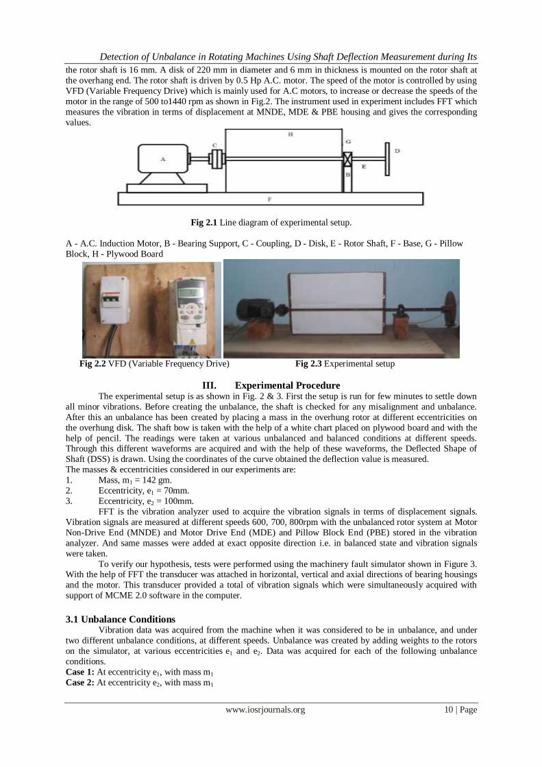
II. Description Of The Experimental Setup The Experimental apparatus consists of a 0.5 Hp A.C. Induction motor, a fixed type flange coupling
and a single disk rotor as shown in Figure 2 & 3.The rotor shaft has a length of 1000 mm with a bearing span of
750 mm, and is supported by a single identical ball bearing (pillow block) as shown in Fig.3. The diameter of
Detection of Unbalance in Rotating Machines Using Shaft Deflection Measurement during Its
www.iosrjournals.org 10 | Page
the rotor shaft is 16 mm. A disk of 220 mm in diameter and 6 mm in thickness is mounted on the rotor shaft at
the overhang end. The rotor shaft is driven by 0.5 Hp A.C. motor. The speed of the motor is controlled by using
VFD (Variable Frequency Drive) which is mainly used for A.C motors, to increase or decrease the speeds of the
motor in the range of 500 to1440 rpm as shown in Fig.2. The instrument used in experiment includes FFT which
measures the vibration in terms of displacement at MNDE, MDE & PBE housing and gives the corresponding
values.
Fig 2.1 Line diagram of experimental setup.
A - A.C. Induction Motor, B - Bearing Support, C - Coupling, D - Disk, E - Rotor Shaft, F - Base, G - Pillow
Block, H - Plywood Board
Fig 2.2 VFD (Variable Frequency Drive) Fig 2.3 Experimental setup
III. Experimental Procedure The experimental setup is as shown in Fig. 2 & 3. First the setup is run for few minutes to settle down
all minor vibrations. Before creating the unbalance, the shaft is checked for any misalignment and unbalance.
After this an unbalance has been created by placing a mass in the overhung rotor at different eccentricities on
the overhung disk. The shaft bow is taken with the help of a white chart placed on plywood board and with the
help of pencil. The readings were taken at various unbalanced and balanced conditions at different speeds. Through this different waveforms are acquired and with the help of these waveforms, the Deflected Shape of
Shaft (DSS) is drawn. Using the coordinates of the curve obtained the deflection value is measured.
The masses & eccentricities considered in our experiments are:
1. Mass, m1 = 142 gm.
2. Eccentricity, e1 = 70mm.
3. Eccentricity, e2 = 100mm.
FFT is the vibration analyzer used to acquire the vibration signals in terms of displacement signals.
Vibration signals are measured at different speeds 600, 700, 800rpm with the unbalanced rotor system at Motor
Non-Drive End (MNDE) and Motor Drive End (MDE) and Pillow Block End (PBE) stored in the vibration
analyzer. And same masses were added at exact opposite direction i.e. in balanced state and vibration signals
were taken.
To verify our hypothesis, tests were performed using the machinery fault simulator shown in Figure 3. With the help of FFT the transducer was attached in horizontal, vertical and axial directions of bearing housings
and the motor. This transducer provided a total of vibration signals which were simultaneously acquired with
support of MCME 2.0 software in the computer.
3.1 Unbalance Conditions
Vibration data was acquired from the machine when it was considered to be in unbalance, and under
two different unbalance conditions, at different speeds. Unbalance was created by adding weights to the rotors
on the simulator, at various eccentricities e1 and e2. Data was acquired for each of the following unbalance
conditions.
Case 1: At eccentricity e1, with mass m1
Case 2: At eccentricity e2, with mass m1

Detection of Unbalance in Rotating Machines Using Shaft Deflection Measurement during Its
www.iosrjournals.org 11 | Page
3.2 Balance Conditions Similarly vibration data was acquired from the machine when it was considered to be in balance, and
under two different balance conditions, at different speeds. Balance was created by adding weights to the rotors
opposite direction on the same radial line of equal distances on the disk of the simulator, at various eccentricities e1 and e2. Data was acquired for each of the following balance conditions.
Case 3: At eccentricity e1, with mass m1
Case 4: At eccentricity e2, with mass m1
IV. Formulation
4.1 Theoretical Calculation Deflection between supports is calculated and formulated as
follows:
∆x = [(1/24Eil) *wx (l4 – 2l2x2 + lx3 – 2a2l2 +2a2x2)] + [(Pax/6Eil) * (l2–x2)]
Where, ∆x = Deflection
E = Young‟s modulus
i = Moment of Inertia
l = Length of the shaft between supports
a = Overhang length of the shaft
x = Distance from left end support
w = Uniformly Distributed Load
P = Load at the end Fig 4.1 Overhanging Beam
4.2 Experimental Results The experimental deflection at various positions of shaft in unbalance condition are taken by
considering the case 1 & 2 in unbalance condition and case 3 & 4 in balance condition, at three different speeds
of 600, 700 & 800rpm, we get the following experimental results.
Fig 4.2 Experimental result of case 1 in unbalance condition
Fig 4.3 Experimental result of case 2 in unbalance condition
Fig 4.4 Experimental result of case 3 in balance condition
Detection of Unbalance in Rotating Machines Using Shaft Deflection Measurement during Its
www.iosrjournals.org 12 | Page
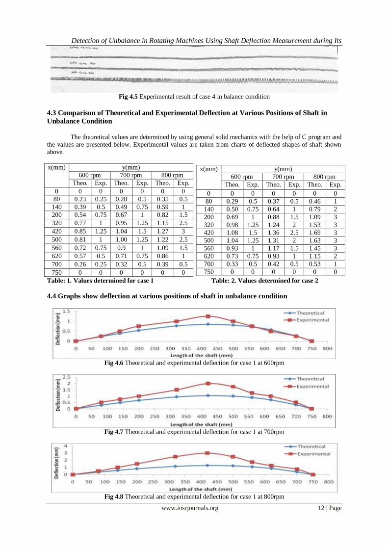
Fig 4.5 Experimental result of case 4 in balance condition
4.3 Comparison of Theoretical and Experimental Deflection at Various Positions of Shaft in
Unbalance Condition
The theoretical values are determined by using general solid mechanics with the help of C program and
the values are presented below. Experimental values are taken from charts of deflected shapes of shaft shown
above.
x(mm) y(mm)
600 rpm 700 rpm 800 rpm
Theo. Exp. Theo. Exp. Theo. Exp.
0 0 0 0 0 0 0
80 0.23 0.25 0.28 0.5 0.35 0.5
140 0.39 0.5 0.49 0.75 0.59 1
200 0.54 0.75 0.67 1 0.82 1.5
320 0.77 1 0.95 1.25 1.15 2.5
420 0.85 1.25 1.04 1.5 1.27 3
500 0.81 1 1.00 1.25 1.22 2.5
560 0.72 0.75 0.9 1 1.09 1.5
620 0.57 0.5 0.71 0.75 0.86 1
700 0.26 0.25 0.32 0.5 0.39 0.5
750 0 0 0 0 0 0
Table: 1. Values determined for case 1 Table: 2. Values determined for case 2
4.4 Graphs show deflection at various positions of shaft in unbalance condition
Fig 4.6 Theoretical and experimental deflection for case 1 at 600rpm
Fig 4.7 Theoretical and experimental deflection for case 1 at 700rpm
Fig 4.8 Theoretical and experimental deflection for case 1 at 800rpm
x(mm) y(mm)
600 rpm 700 rpm 800 rpm
Theo. Exp. Theo. Exp. Theo. Exp.
0 0 0 0 0 0 0
80 0.29 0.5 0.37 0.5 0.46 1
140 0.50 0.75 0.64 1 0.79 2
200 0.69 1 0.88 1.5 1.09 3
320 0.98 1.25 1.24 2 1.53 3
420 1.08 1.5 1.36 2.5 1.69 3
500 1.04 1.25 1.31 2 1.63 3
560 0.93 1 1.17 1.5 1.45 3
620 0.73 0.75 0.93 1 1.15 2
700 0.33 0.5 0.42 0.5 0.53 1
750 0 0 0 0 0 0
Detection of Unbalance in Rotating Machines Using Shaft Deflection Measurement during Its
www.iosrjournals.org 13 | Page
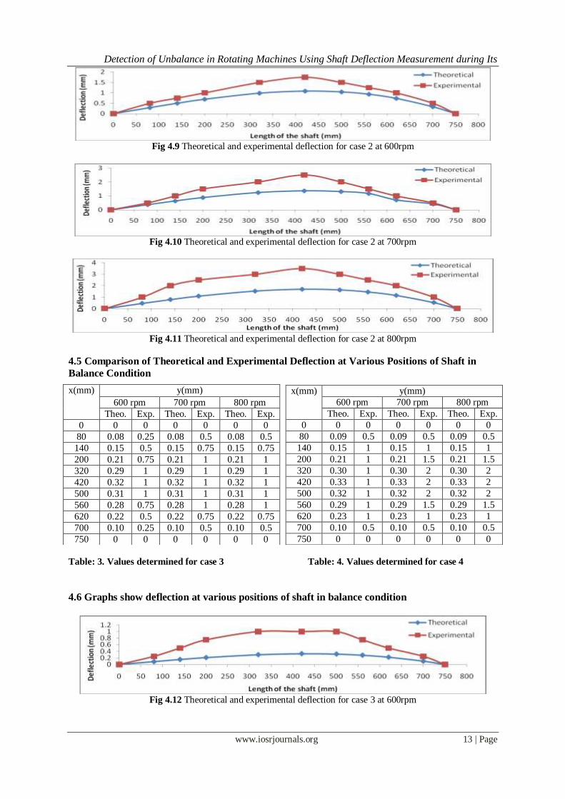
Fig 4.9 Theoretical and experimental deflection for case 2 at 600rpm
Fig 4.10 Theoretical and experimental deflection for case 2 at 700rpm
Fig 4.11 Theoretical and experimental deflection for case 2 at 800rpm
4.5 Comparison of Theoretical and Experimental Deflection at Various Positions of Shaft in
Balance Condition
Table: 3. Values determined for case 3 Table: 4. Values determined for case 4
4.6 Graphs show deflection at various positions of shaft in balance condition
Fig 4.12 Theoretical and experimental deflection for case 3 at 600rpm
x(mm) y(mm)
600 rpm 700 rpm 800 rpm
Theo. Exp. Theo. Exp. Theo. Exp.
0 0 0 0 0 0 0
80 0.08 0.25 0.08 0.5 0.08 0.5
140 0.15 0.5 0.15 0.75 0.15 0.75
200 0.21 0.75 0.21 1 0.21 1
320 0.29 1 0.29 1 0.29 1
420 0.32 1 0.32 1 0.32 1
500 0.31 1 0.31 1 0.31 1
560 0.28 0.75 0.28 1 0.28 1
620 0.22 0.5 0.22 0.75 0.22 0.75
700 0.10 0.25 0.10 0.5 0.10 0.5
750 0 0 0 0 0 0
x(mm) y(mm)
600 rpm 700 rpm 800 rpm
Theo. Exp. Theo. Exp. Theo. Exp.
0 0 0 0 0 0 0
80 0.09 0.5 0.09 0.5 0.09 0.5
140 0.15 1 0.15 1 0.15 1
200 0.21 1 0.21 1.5 0.21 1.5
320 0.30 1 0.30 2 0.30 2
420 0.33 1 0.33 2 0.33 2
500 0.32 1 0.32 2 0.32 2
560 0.29 1 0.29 1.5 0.29 1.5
620 0.23 1 0.23 1 0.23 1
700 0.10 0.5 0.10 0.5 0.10 0.5
750 0 0 0 0 0 0

Detection of Unbalance in Rotating Machines Using Shaft Deflection Measurement during Its
www.iosrjournals.org 14 | Page
Fig 4.13 Theoretical and experimental deflection for case 3 at 700rpm
Fig 4.14 Theoretical and experimental deflection for case 3 at 800rpm
Fig 4.15 Theoretical and experimental deflection for case 4 at 600rpm
Fig 4.16 Theoretical and experimental deflection for case 4 at 700rpm
Fig 4.17 Theoretical and experimental deflection for case 4 at 800rpm
V. Vibration Readings Observed Using FFT
5.1 Vibration readings at unbalanced condition for case 1
Speed
(rpm)
MNDE MDE PBE
H V A H V A H V A
600 111 34.7 175 113 154 142 349 567 98.5
700 207 44.2 296 213 209 219 688 1394 268
800 444 112 857 487 579 823 1548 4004 799
Table: 5
Above readings show that high vibrations are present at PBE. At all speeds vibrations in radial direction are higher than axial direction. High radial vibrations are present due to unbalance, misalignment and
bending of the shaft. To determine the cause of high vibrations spectrum analysis was carried. Following are the
spectrums taken at different speeds using FFT Analyzer with the support of Mcme2.0 software.
Detection of Unbalance in Rotating Machines Using Shaft Deflection Measurement during Its
www.iosrjournals.org 15 | Page
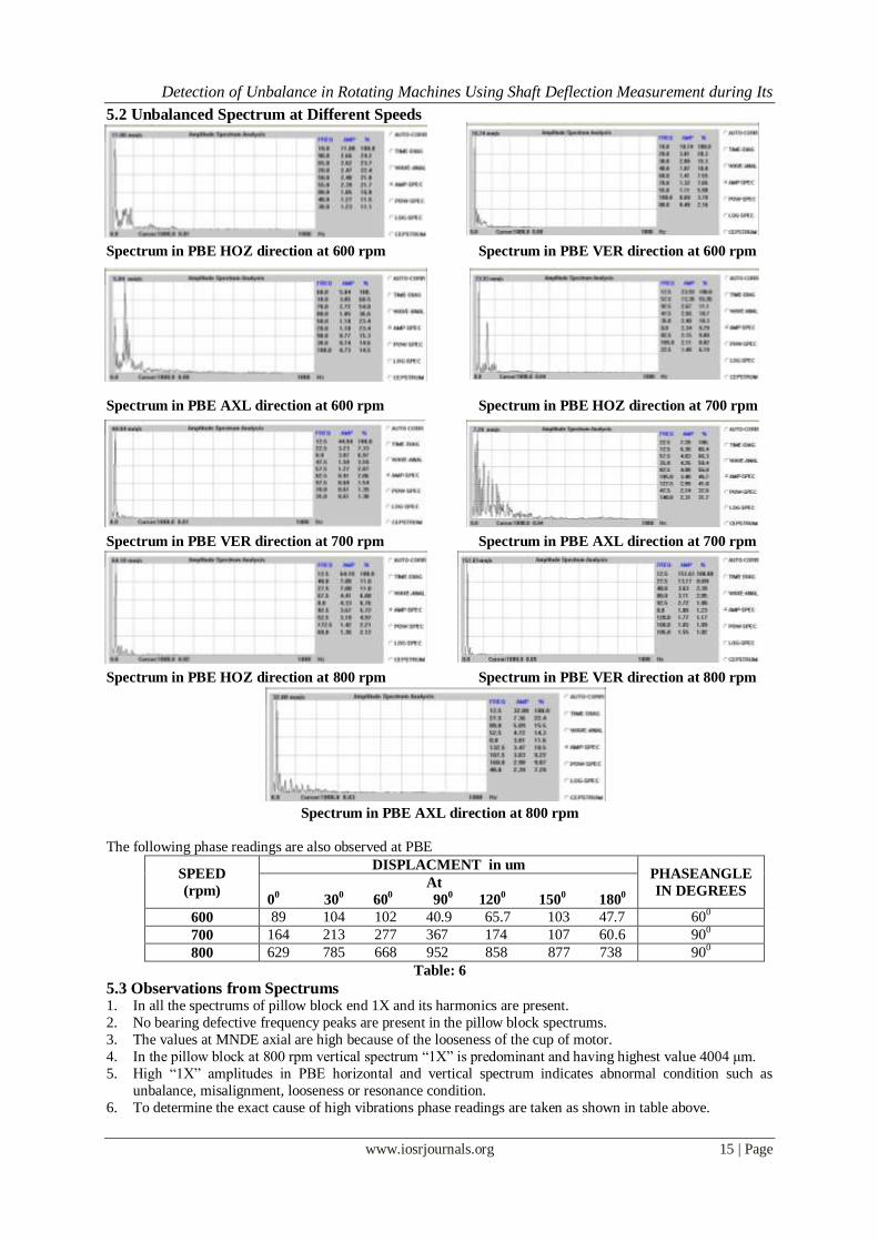
5.2 Unbalanced Spectrum at Different Speeds
Spectrum in PBE HOZ direction at 600 rpm Spectrum in PBE VER direction at 600 rpm
Spectrum in PBE AXL direction at 600 rpm Spectrum in PBE HOZ direction at 700 rpm
Spectrum in PBE VER direction at 700 rpm Spectrum in PBE AXL direction at 700 rpm
Spectrum in PBE HOZ direction at 800 rpm Spectrum in PBE VER direction at 800 rpm
Spectrum in PBE AXL direction at 800 rpm
The following phase readings are also observed at PBE
SPEED
(rpm)
DISPLACMENT in um PHASEANGLE
IN DEGREES At
00 30
0 60
0 90
0 120
0 150
0 180
0
600 89 104 102 40.9 65.7 103 47.7 600
700 164 213 277 367 174 107 60.6 900
800 629 785 668 952 858 877 738 900
Table: 6
5.3 Observations from Spectrums 1. In all the spectrums of pillow block end 1X and its harmonics are present.
2. No bearing defective frequency peaks are present in the pillow block spectrums.
3. The values at MNDE axial are high because of the looseness of the cup of motor.
4. In the pillow block at 800 rpm vertical spectrum “1X” is predominant and having highest value 4004 μm.
5. High “1X” amplitudes in PBE horizontal and vertical spectrum indicates abnormal condition such as
unbalance, misalignment, looseness or resonance condition.
6. To determine the exact cause of high vibrations phase readings are taken as shown in table above.
Detection of Unbalance in Rotating Machines Using Shaft Deflection Measurement during Its
www.iosrjournals.org 16 | Page
5.4 Observation from Phase Analysis 1. From the phase reading at the PBE it is observed that there is 900 phase difference between the PBE
horizontal and vertical.
2. 900 phase difference between horizontal and vertical reveals that there is presence of an unbalance at PBE. 3. From the spectrum analysis and phase analysis it is conformed that there is a presence of mass unbalance in
the PBE.
Rotor was removed and balanced weight is added diametrically opposite to unbalanced mass and vibration
readings were taken after balancing. Vibration readings are shown in following table.
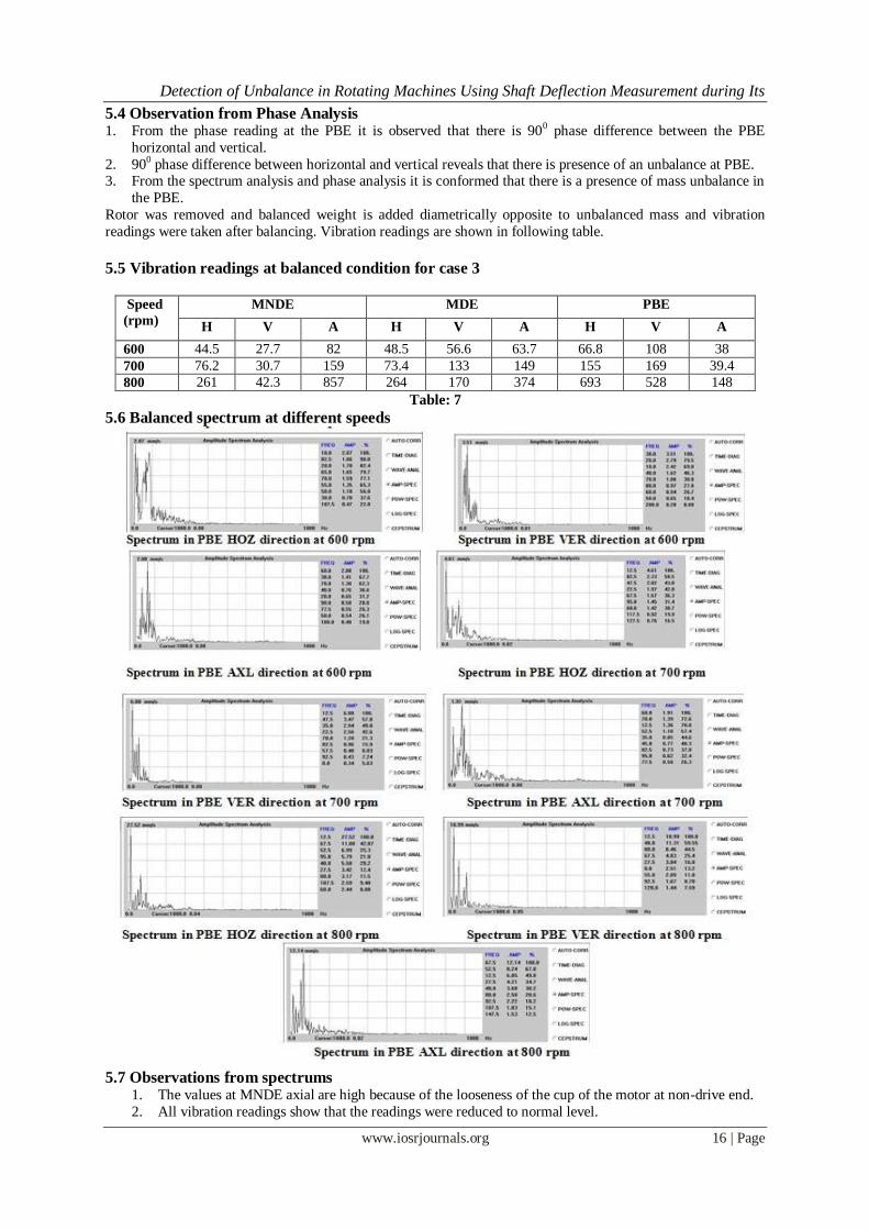
5.5 Vibration readings at balanced condition for case 3
Speed
(rpm)
MNDE MDE PBE
H V A H V A H V A
600 44.5 27.7 82 48.5 56.6 63.7 66.8 108 38
700 76.2 30.7 159 73.4 133 149 155 169 39.4
800 261 42.3 857 264 170 374 693 528 148
Table: 7
5.6 Balanced spectrum at different speeds
5.7 Observations from spectrums
1. The values at MNDE axial are high because of the looseness of the cup of the motor at non-drive end.
2. All vibration readings show that the readings were reduced to normal level.

Detection of Unbalance in Rotating Machines Using Shaft Deflection Measurement during Its
www.iosrjournals.org 17 | Page
5.8 Graphs show Vibration amplitude against speed, comparison with unbalance and balance
Vibration amplitude at PBE HOZ against speed Vibration amplitude at PBE VER against speed
Vibration amplitude at PBE AXL against speed
5.9 Vibration readings at unbalanced condition for case 2
Speed
(rpm)
MNDE MDE PBE
H V A H V A H V A
600 189 142 591 216 199 472 1489 1414 334
700 402 255 1081 409 905 855 1500 2396 1090
800 1397 1002 5202 1259 3717 3818 5300 6054 1627
Table: 9
Above readings show that high vibrations are present at PBE. At all speeds vibrations in radial direction are higher than axial direction. High radial vibrations are present due to unbalance, misalignment and
bending of the shaft. To determine the cause of high vibrations spectrum analysis was carried. Following are the
spectrums taken at different speeds using FFT Analyzer with the support of Mcme2.0 software.
5.10 Unbalanced spectrum at different speeds
Spectrum in PBE HOZ direction at 600 rpm Spectrum in PBE VER direction at 600 rpm
Spectrum in PBE AXL direction at 600 rpm Spectrum in PBE HOZ direction at 700 rpm
Spectrum in PBE VER direction at 700 rpm Spectrum in PBE AXL direction at 700 rpm
Detection of Unbalance in Rotating Machines Using Shaft Deflection Measurement during Its
www.iosrjournals.org 18 | Page
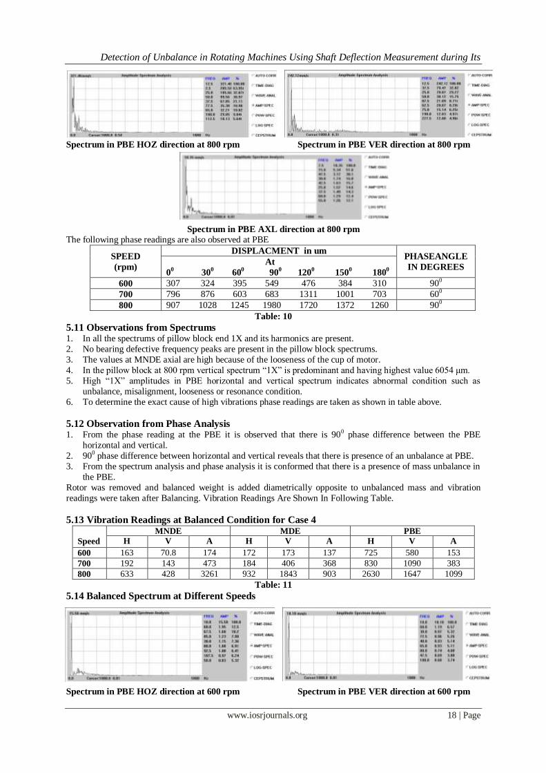
Spectrum in PBE HOZ direction at 800 rpm Spectrum in PBE VER direction at 800 rpm
Spectrum in PBE AXL direction at 800 rpm
The following phase readings are also observed at PBE
SPEED
(rpm)
DISPLACMENT in um PHASEANGLE
IN DEGREES At
00 30
0 60
0 90
0 120
0 150
0 180
0
600 307 324 395 549 476 384 310 900
700 796 876 603 683 1311 1001 703 600
800 907 1028 1245 1980 1720 1372 1260 900
Table: 10
5.11 Observations from Spectrums 1. In all the spectrums of pillow block end 1X and its harmonics are present.
2. No bearing defective frequency peaks are present in the pillow block spectrums.
3. The values at MNDE axial are high because of the looseness of the cup of motor.
4. In the pillow block at 800 rpm vertical spectrum “1X” is predominant and having highest value 6054 μm.
5. High “1X” amplitudes in PBE horizontal and vertical spectrum indicates abnormal condition such as
unbalance, misalignment, looseness or resonance condition.
6. To determine the exact cause of high vibrations phase readings are taken as shown in table above.
5.12 Observation from Phase Analysis 1. From the phase reading at the PBE it is observed that there is 900 phase difference between the PBE
horizontal and vertical.
2. 900 phase difference between horizontal and vertical reveals that there is presence of an unbalance at PBE.
3. From the spectrum analysis and phase analysis it is conformed that there is a presence of mass unbalance in
the PBE.
Rotor was removed and balanced weight is added diametrically opposite to unbalanced mass and vibration
readings were taken after Balancing. Vibration Readings Are Shown In Following Table.
5.13 Vibration Readings at Balanced Condition for Case 4
Speed
(rpm)
MNDE MDE PBE
H V A H V A H V A
600 163 70.8 174 172 173 137 725 580 153
700 192 143 473 184 406 368 830 1090 383
800 633 428 3261 932 1843 903 2630 1647 1099
Table: 11
5.14 Balanced Spectrum at Different Speeds
Spectrum in PBE HOZ direction at 600 rpm Spectrum in PBE VER direction at 600 rpm
Detection of Unbalance in Rotating Machines Using Shaft Deflection Measurement during Its
www.iosrjournals.org 19 | Page
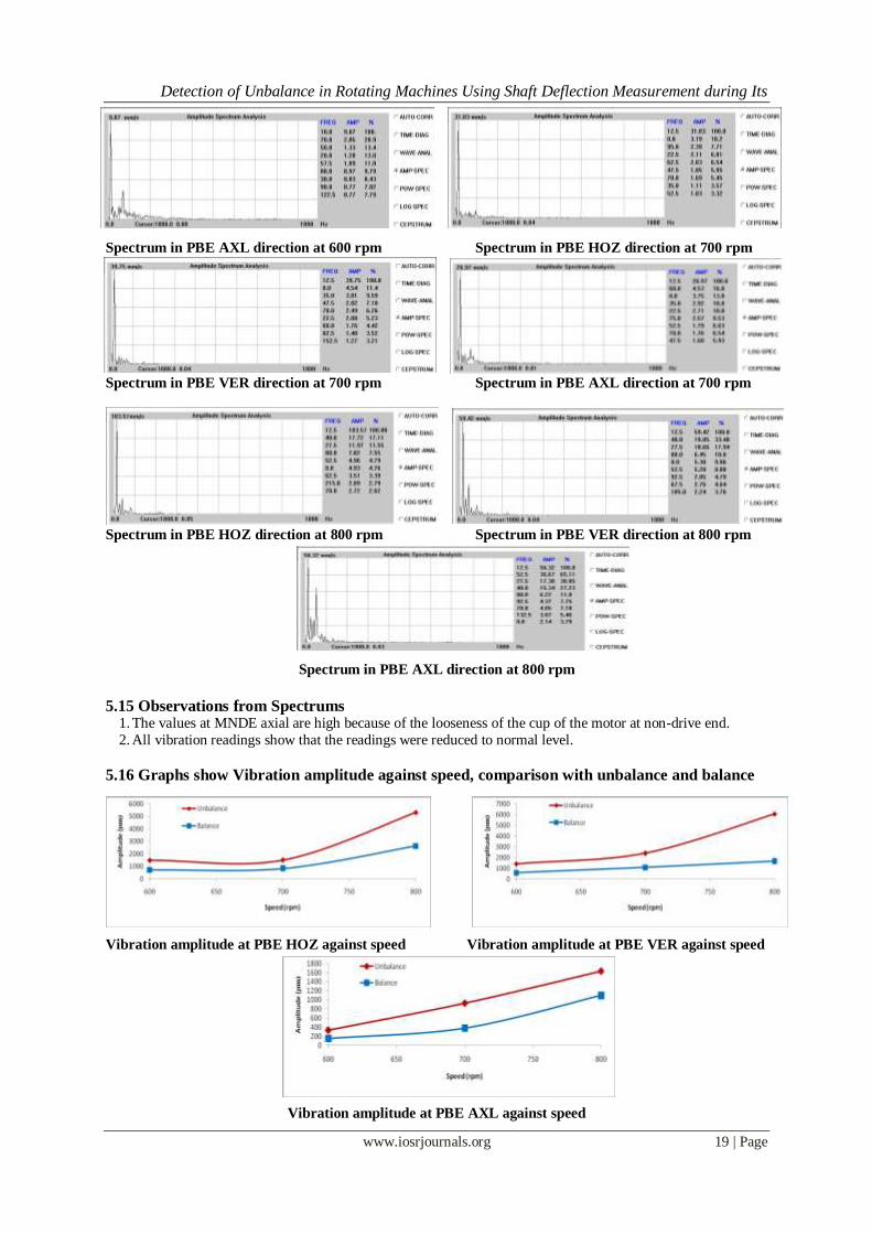
Spectrum in PBE AXL direction at 600 rpm Spectrum in PBE HOZ direction at 700 rpm
Spectrum in PBE VER direction at 700 rpm Spectrum in PBE AXL direction at 700 rpm
Spectrum in PBE HOZ direction at 800 rpm Spectrum in PBE VER direction at 800 rpm
Spectrum in PBE AXL direction at 800 rpm
5.15 Observations from Spectrums 1. The values at MNDE axial are high because of the looseness of the cup of the motor at non-drive end.
2. All vibration readings show that the readings were reduced to normal level.
5.16 Graphs show Vibration amplitude against speed, comparison with unbalance and balance
Vibration amplitude at PBE HOZ against speed Vibration amplitude at PBE VER against speed
Vibration amplitude at PBE AXL against speed

Detection of Unbalance in Rotating Machines Using Shaft Deflection Measurement during Its
www.iosrjournals.org 20 | Page
VI. Conclusion As the speed increases the amplitude at 1X is also increases for the same unbalance weight. This
increase in amplitude value is because of the increase of centrifugal force. Since the system frequency is nearer
to 900rpm due to the presence of resonance at this speed higher amplitudes were presented at 800rpm. Spectrum analysis shows that their presence of 1X amplitudes in radial directions. A high radial vibration with phase angle
900 causes the presence of unbalance. Rotor is balanced and vibration readings are taken after balancing. It was
shown that amplitude of vibration is reduced drastically. The presence of unbalance causes deflected shape
shaft. By measuring the maximum deflection from the shaft magnitude of unbalance can be determined using
general solid mechanics formulae.
This paper outlines and showed the deflected shapes of shaft in different cases of presence of unbalance
and the same is compared with deflected shapes of shaft in balanced conditions. This is very new method in
determining the mechanical fault in rotating machines. This method reduces the maintenance cost drastically as
it doesn‟t require sophisticated tools like FFT.
This is an NDT method to detect the fault in rotating machine. Hence Deflected shape of shaft method
reduces the maintenance cost when it is applied to industries and improves the profit. In this paper gyroscopic effect is not considered. If we consider the gyroscopic effect, the experimental
values will be close to the theoretical values. The work may be extended for misalignment, looseness etc.
References [1] Surendra N. Ganeriwala (Suri), Brian Schwarz & Mark H. Richardson “Using Operating Deflection Shapes to Detect Unbalance in
Rotating Equipment” Sound and Vibration, May 2009.
[2] Zhunag li, Surendra N. Ganeriwala & Mark H. Richardson “Using Operating Deflection Shapes to Detect Unbalance in Rotating
Equipment” Proceedings of International Modal Analysis Conference(XXVI),February,2008.
[3] William W. Clark, Joo-Hyung Kim, Roy D. Marangoni, “Active Control of Dynamic Bearing Loads in Rotating Machinery Using
the Deflection Coefficient Method for Load Estimation”, International Journal of Acoustics and Vibration.
[4] Kevin Gatzwiller, Brüel & Kjær, “Measuring Torsional Operational Deflection Shapes of Rotating Shafts”, Brüel & Kjær, World
Headquarters, DK-2850 Nwum . Denmark.
[5] M.H. Richardson, “Is It a Mode Shape or an Operating Deflection Shape?” Sound and Vibration magazine, March, 1997.
[6] Seshendra Kumar.K.V.S, SundaraSiva Rao.B.S.K, “Experimental investigation of unbalance response of geared shaft rotor system”,
International Journal Of Applied Engineering Research, Dindigul, Volume 1, No 3, 2010
[7] Troy D. Feese P.E, Phillip E. Grazier, “Balance this: Case histories from difficult balance jobs” presented at 33rd
Turbo machinery
Symposium. Sept., 2004.
[8] Gupta, K.D. Gupta and K. Athre, 1993. “Unbalance response of a dual rotor system: theory and experiment”, Transactions J.
Vibration Acoustics, 115: 427-435.
[9] D. G. Dorrell, “Experimental behavior of unbalanced magnetic pull in 3-phase induction motors with eccentric rotors and the
relationship with tooth saturation,” IEEE Trans. Energy Conversion, vol. 14, pp. 304–309, Sept. 1999.
[10] Ray D. Kelm, “Advanced Field Balancing Techniques”, P.E. Kelm Engineering Danbury, TX, 24-06-2008.
[11] Lev Nelik, Charles Jackson, “Effect of mechanical unbalance on vibrations, forces and reliability of a single stage centrifugal
pump”, Proceedings of Twelfth International Pump Users Symposium.
[12] Seok-Myeong Jang, Member, IEEE, Sung-Ho Lee, Han-Wook Cho, and Sung-Kook Cho, “Analysis of Unbalanced Force for High-
Speed Slotless Permanent Magnet Machine with Halbach Array”, IEEE TRANSACTIONS ON MAGNETICS, VOL. 39, NO. 5,
SEPTEMBER 2003.
[13] Rao, T.N.Shiau and J.R. Chang, 1998. “Theoretical analysis of lateral response due to torsion excitation of geared rotor”,
Mechanism and Machine. Theory, 33(6): 761-783.Coupled lateral-torsional vibration of rotor.
[14] R.K.Biswas “vibration based condition monitoring of rotating machines” national conference on condition monitoring [NCCM-
2006] December 2006 pg no 34-40.
[15] R.A Collacat “condition monitoring” published by M c Graw Hill, New Delhi 1998.
[16] A.V.Barkov, N.A.Barkova, and A.Yu. Azovtsev, "Condition Monitoring and Diagnostics of Rotating Machines Using Vibration
analysis", VAST, Inc., St. Petersburg, Russia, 1997.
[17] “A comparison of shaft deflection measurements” Chapter Three, The Modern Guide to Shaft Fitting.
[18] S. Edwards, A.W. Lees, M.I. Friswell, “Fault Diagnosis Of Rotating Machinery”, Shock and Vibration Digest, Vol. 30, No. 1, pp.
4-13, 1998.