Detection and Control Components - Ansul Home and Control Components FCM-1 Control Module...
98
Detection and Control Components FCM-1 Control Module (IQ-318/IQ-636X-2) Features • Built-in type identification automatically identifies these devices to the control unit • Internal circuitry and relay powered directly by two-wire SLC loop; requires power for notification • Integral LED blinks green each time a communication is received from the control unit and turns on in steady red when activated • LED blink may be deselected globally (affects all devices) • High noise immunity (EMF/RFI) • Wide viewing angle of LED • SEMS screws with clamping plates for wiring ease • Direct-dial entry of address (01-159) • Audible/visual applications may be wired for Class B or A (Style Y or Z) • Face plate is made of off-white Noryl® • Configured for a single Class B (Style Y) or Class A (Style Z) Notification Appliance Circuit • FlashScan® communication protocol Applications The FCM-1 Addressable Control Module provides the AUTOPULSE IQ-318, or IQ-636X-2 control unit a circuit for Notification Appliances (horns, strobes, speakers, etc.). Addressability allows the FCM-1 to be activated, either man- ually or through panel programming, on a select (zone or area of coverage) basis. FlashScan (U.S. Patent 5,539,389) is a new communication protocol that greatly enhances the speed of communication between analog intelligent devices. Intelligent devices com- municate in a grouped fashion. If one of the devices within the group has new information, the panel CPU stops the group poll and concentrates on single points. The net effect is response speed greater than five times that of other designs. Description Each FCM-1 Control Module uses one of 159 possible mod- ule addresses on a SLC loop. It responds to regular polls from the control unit and reports its type and status, including the open/normal/short status of its Notification Appliance Circuit (NAC). The LED blinks with each poll received. On command, it activates its internal relay. The FCM-1 supervis- es Class B (Style Y) or Class A (Style Z) notification or control circuits. The FCM-1 can be used to replace the CMX-2 mod- ule, Part No. 417479, in existing systems. Upon code command from the unit, the FCM-1 will discon- nect the supervision and connect the external power supply in the proper polarity across the load device. The disconnec- tion of the supervision provides a positive indication to the panel that the control relay actually turned ON. The external power supply is always relay isolated from the communica- tion loop so that a trouble condition on the external power supply will never interfere with the rest of the system. Rotary switches set a unique address for each module. The address may be set before or after mounting. The built-in TYPE CODE (not settable) will identify the module to the control panel, so as to differentiate between a module and a sensor address. The FCM-1 is used to switch 24 VDC audible/visual or releasing appliance power. Technical Information Normal Operating Voltage: . . . . . . . . . . . . . . . . 15 to 32 VDC Maximum Current Draw: . . . . . . . . . . . . . . . . 5.1 mA (LED on) Average Operating Current: . . . . . . . . . 390 μA (LED flashing) Maximum NAC Current Rating: Class B wiring system: . . . . . . . . . . . . . . . . . . . . . . . . . . . 3A Class A wiring system: . . . . . . . . . . . . . . . . . . . . . . . . . . . . 2A External Supply Voltage . . . . . . . . max 80 volts (RMS or DC) between T3 and T4: Drain on External. . . . . . 2 μA max. (using internal EOL relay) Supply: EOL Resistance: . . . . . . . . . . . . . . . . . . . . . . . . . . . 47 K ohms Temperature Range:. . . . . . . . 32 °F to 120 °F (0 °C to 49 °C) Humidity Range: . . . . . . . . . . . . 10% to 93% non-condensing FCM-1 CONTROL MODULE Note: The CB500 barrier is required by UL for separating power-limited and non-power limited wiring in the same junc- tion box. 3-29 004749 ISOLATED QUADRANT
Transcript of Detection and Control Components - Ansul Home and Control Components FCM-1 Control Module...

Detection and Control Components
FCM-1 Control Module (IQ-318/IQ-636X-2)
Features
• Built-in type identification automatically identifies thesedevices to the control unit
• Internal circuitry and relay powered directly by two-wireSLC loop; requires power for notification
• Integral LED blinks green each time a communication isreceived from the control unit and turns on in steady redwhen activated
• LED blink may be deselected globally (affects all devices)
• High noise immunity (EMF/RFI)
• Wide viewing angle of LED
• SEMS screws with clamping plates for wiring ease
• Direct-dial entry of address (01-159)
• Audible/visual applications may be wired for Class B or A(Style Y or Z)
• Face plate is made of off-white Noryl®
• Configured for a single Class B (Style Y) or Class A (StyleZ) Notification Appliance Circuit
• FlashScan® communication protocol
Applications
The FCM-1 Addressable Control Module provides theAUTOPULSE IQ-318, or IQ-636X-2 control unit a circuit forNotification Appliances (horns, strobes, speakers, etc.).Addressability allows the FCM-1 to be activated, either man-ually or through panel programming, on a select (zone orarea of coverage) basis.
FlashScan (U.S. Patent 5,539,389) is a new communicationprotocol that greatly enhances the speed of communicationbetween analog intelligent devices. Intelligent devices com-municate in a grouped fashion. If one of the devices within thegroup has new information, the panel CPU stops the grouppoll and concentrates on single points. The net effect isresponse speed greater than five times that of other designs.
Description
Each FCM-1 Control Module uses one of 159 possible mod-ule addresses on a SLC loop. It responds to regular pollsfrom the control unit and reports its type and status, includingthe open/normal/short status of its Notification ApplianceCircuit (NAC). The LED blinks with each poll received. Oncommand, it activates its internal relay. The FCM-1 supervis-es Class B (Style Y) or Class A (Style Z) notification or controlcircuits. The FCM-1 can be used to replace the CMX-2 mod-ule, Part No. 417479, in existing systems.
Upon code command from the unit, the FCM-1 will discon-nect the supervision and connect the external power supplyin the proper polarity across the load device. The disconnec-tion of the supervision provides a positive indication to thepanel that the control relay actually turned ON. The external
power supply is always relay isolated from the communica-tion loop so that a trouble condition on the external powersupply will never interfere with the rest of the system.
Rotary switches set a unique address for each module. Theaddress may be set before or after mounting. The built-inTYPE CODE (not settable) will identify the module to thecontrol panel, so as to differentiate between a module and asensor address.
The FCM-1 is used to switch 24 VDC audible/visual orreleasing appliance power.
Technical InformationNormal Operating Voltage: . . . . . . . . . . . . . . . . 15 to 32 VDCMaximum Current Draw:. . . . . . . . . . . . . . . . 5.1 mA (LED on)Average Operating Current:. . . . . . . . . 390 μA (LED flashing)Maximum NAC Current Rating:Class B wiring system: . . . . . . . . . . . . . . . . . . . . . . . . . . . 3AClass A wiring system:. . . . . . . . . . . . . . . . . . . . . . . . . . . . 2A
External Supply Voltage . . . . . . . . max 80 volts (RMS or DC)between T3 and T4:
Drain on External. . . . . . 2 μA max. (using internal EOL relay)Supply:
EOL Resistance:. . . . . . . . . . . . . . . . . . . . . . . . . . . 47 K ohmsTemperature Range:. . . . . . . . 32 °F to 120 °F (0 °C to 49 °C)Humidity Range: . . . . . . . . . . . . 10% to 93% non-condensing
FCM-1 CONTROL MODULE
Note: The CB500 barrier is required by UL for separatingpower-limited and non-power limited wiring in the same junc-tion box.
3-29
004749
ISOLATEDQUADRANT

FCM-1 MODULE
007271
Listings and Approvals*UL. . . . . . . . . . . . . . . . . . . . . . . . . . . . . . . . . . . . . . . . . . . S635ULC . . . . . . . . . . . . . . . . . . . . . . . . . . . . . . . . . . . . . . . . CS669Factory Mutual (FM) . . . . . . . . . . . . . . . . . . . . . . . . . ApprovedCalifornia State Fire Marshal (CSFM). . . . . . . 7300-0028:202MEA (NYC) . . . . . . . . . . . . . . . . . . . . . . . . . . . . . . . . 457-99-EMaryland State Fire Marshal. . . . . . . . . . . . . . . Permit # 2020USCG . . . . . . . . . . . . . . . . . . . . . . . . . . . . . . . . 161.002/A42/1* Listings and Approvals are under NOTIFIER.
Ordering InformationShipping Weight
Part No. Description lb (kg)
428101 FCM-1 Intelligent 1 (0.45)Control Module
437066 FCM-1A Intelligent Control 1 (0.45)Module (ULC)
419639 Releasing Device, REL-47K 0.5 (0.23)
437071 Releasing Device, REL-47K 1 (0.45)BP (ULC)
436202 CB500 Barrier 0.5 (0.23)
TYPICAL CONNECTION OF A 24 VDC NOTIFICATION DEVICE TO THE FCM-1 MODULE
008862
MODULE POLARITIES ARESHOWN IN ALARM
47K EOLREESISTORELR-47K
FROM PANELOR PREVIOUSDEVICE
TO NEXTDEVICE
CONTROLMODULE
TO NEXT CONTROL MODULE OR END-OF-LINE RELAY. ONE RELAY REQUIRED FOREACH CIRCUIT. SOME CONTROL PANELSHAVE RELAY BUILT IN AND DO NOTREQUIRE EXTERNAL WIRING. REFER TOPANEL MANUAL.
24 VDC CIRCUIT. DO NOT LOOP WIRE ONTERMINALS 10 & 11. BREAK WIRE RUN TOPROVIDE SUPERVISION OF CONNECTIONS.
24 VDC POWER SUPPLYISOLATED, REGULATED, POWERLIMITED PER NFPA 70. LISTEDFOR FIRE PROTECTION WITHBATTERY BACKUP.
UL LISTED EOL RELAYSHOWN ENERGIZED24 VDC COIL EOLR-1
FlashScan is a trademark of Honeywell International. Noryl is a registered trademark of GE Plastics, a subsidiary of General Electric Company.
TYCO FIRE PROTECTION PRODUCTS Copyright © 2011 Tyco Fire Protection ProductsONE STANTON STREET All rights reserved.MARINETTE, WI 54143-2542 715-735-7411 Form No. T-2007097-3
SIGNAL LINE CIRCUIT(SLC) 32 VDC MAXIMUM.TWISTED PAIR ISRECOMMENDED.
CONNECT MODULES TO LISTEDCOMPATIBLE CONTROL PANELS ONLY
ALL WIRING SHOWN IS SUPERVISEDAND POWER LIMITED

Detection and Control Components
FCM-1-REL(A) Releasing Control Module(IQ-318/IQ-636X-2)
Features• Redundant protocol for added protection• Configurable for Class A or Class B operation• External supply voltage monitoring• Can power one 24V or two 12V solenoids• SEMS screws for easing wiring• Panel controlled status LED• Analog communications• Rotary address switches• Low standby current• Mounts in standard 4 in. (10.16 cm) junction box• FlashScan® operation
DescriptionThe FCM-1-REL(A) Releasing Control Module is specificallydesigned for fire suppression releasing applications in Flash-Scan systems. Power to the release agent solenoid(s) runsthrough the module for full-time monitoring and supervision.
The FCM-1-REL(A) Releasing Control Module uses a redun-dant protocol; the module must be armed with a pair ofsignals in order to activate. It will then enter a 3-secondwindow awaiting a pair of confirmation signals. If no confir-mation is received, the module will automatically reset. It alsosupervises the wiring to the connected load and reports thestatus to the panel as NORMAL, OPEN, or SHORTCIRCUIT. The module has two pairs of output terminationpoints available for fault-tolerant wiring and a panel-controlled LED indicator. The module may be connected toeither one 24VDC solenoid or up to two 12VDC solenoidsthat are listed with the IQ-318 and IQ-636X-2 panels. Toensure proper operation, this module shall be connected to acompatible AUTOPULSE system control panel only (listavailable upon request). In addition, please refer toAUTOPULSE Device Compatibility Document, Part No.50054, for the list of compatible solenoids.
Note: FCM-1-REL(A) is required for all new FlashScan-mode releasing applications with IQ-318 (version 12.0 orhigher) and IQ-636X-2 (version 12.0 or higher) panels. UseFCM-1 for releasing applications on IQ-636X, IQ-301, andIQ-396X panels.
Technical InformationGENERALOperating Voltage . . . . . . . . . . . . . . . . . . . . . . . 15 to 32 VDC
Communication Line Loop Impedance . . . . . . . 40 Ohm max.
Temperature Range . . . . . . . . . 14°F to 140°F (–10° to 60°C)
Relative Humidity . . . . . . . . . . . . 10% to 95% noncondensing
Shipping Weight. . . . . . . . . . . . . . . . . . . . . . . . . 5.5 oz (156 g)
Dimensions: High . . . . . . . . . . . . . . . . . . . . . 4.7 in. (119 mm)Wide . . . . . . . . . . . . . . . . . . . . 4.3 in. (109 mm)Deep . . . . . . . . . . . . . . . . . . . . . 1.4 in. (36 mm)
SLCAverage Operating Current . . . . . . . . 700 μA max @ 24 VDC
(one communication every 5 sec. with LED enabled)
Maximum Activation Current. . . . . . . . . . . . . 9.0 mA (LED on)
EXTERNAL SUPPLYNormal Operating Voltage . . . . . . . . . . . . . . 24 VDC Nominal
Maximum Line Loss . . . . . . . . . 2.3 VDC (total allowable lossfrom power supply to module and
from module to solenoid)
Minimum Operating Voltageto Activate Solenoid . . . . . . . . . . . . . . . . 18 VDC (at solenoid)
Standby Current . . . . . . . . . . . . . . . . . . . . . . . . . . . . . . 6.4 mA
Activation Current . . . . . . . . . . . . . . . . . . . . . . . . . . . . . 10 mA
SOLENOIDSupervisory Loop Voltage . . . . . . . . . . . . . . . . . . . . . . . . 3.3 V
Supervisory Loop Current (Normal) . . . . . . . . . . . . . . . 30 mA
Maximum Activation Current. . . . . . . . . . . . . . . . . . . . . . . . 2 A
Listings and Approvals*
These listings and approvals apply to the modules specifiedin this document. In some cases, certain modules or applica-tions may not be listed by certain approval agencies, or list-ings may be in process. Consult factory for latest listingstatus.
UL Listed . . . . . . . . . . . . . . . . . . . . . . . . . . . . . . . . . . . . . S635
ULC Listed . . . . . . . . . . . . . . . . . . . . . . . . . . . . (FCM-1-RELA)
FM. . . . . . . . . . . . . . . . . . . . . . . . . . . . . . . . . . . . . . . Approved
CSFM. . . . . . . . . . . . . . . . . . . . . . . . . . . . . . . . 7300-0028:249
*Listings and Approvals are under NOTIFIER.
3-29.1

Ordering Information
Shipping WeightPart No. Description lb (kg)______ _________ _________436861 FCM-1-REL 1 (0.5)
Releasing Control Module
436942 FCM-1-RELA 1 (0.5)Releasing Control Module(ULC Version)
436202 CB500 Control Module 0.5 (0.2)Barrier
FlashScan is a trademark of Honeywell International.
TYCO FIRE PROTECTION PRODUCTS Copyright © 2011 Tyco Fire Protection ProductsONE STANTON STREET All rights reserved.MARINETTE, WI 54143-2542 715-735-7411 Form No. T-2009134-3
TYPICAL CLASS B, SOLENOID CONFIGURATION
008863
POWER SUPPLYSUPERVISION BYMODULE
FROM PANELOR PREVIOUSDEVICE
TO NEXTDEVICE
RELEASINGCONTROL MODULE
TO NEXT MODULE
24 VDC CIRCUIT. DO NOT LOOP WIRE ONTERMINALS 10 & 11. BREAK WIRE RUN TOPROVIDE SUPERVISION OF CONNECTIONS.
24 VDC POWER SUPPLYISOLATED, REGULATED, POWERLIMITED PER NFPA 70. UL 864LISTED FOR RELEASING DEVICEWITH BATTERY BACKUP.
OUTPUT TO A UL LISTED FIREALARM RELEASING SOLENOID(REFER TO PANELMANUFACTURER’SINSTALLATION DOCUMENT)
SIGNAL LINE CIRCUIT(SLC) 32 VDC MAXIMUM.TWISTED PAIR ISRECOMMENDED.
CONNECT MODULES TO LISTEDCOMPATIBLE CONTROL PANELS ONLY
ALL WIRING SHOWN IS SUPERVISEDAND POWER LIMITED

Features
• Built-in type identification automatically identifies thesedevices to the control unit
• Internal circuitry and relay powered directly by two-wireSLC loop
• Integral LED blinks green each time a communication isreceived from the control unit and turns on in steady redwhen activated
• LED blink may be deselected globally (affects all devices)
• High noise immunity (EMF/RFI)
• Wide viewing angle of LED
• SEMS screws with clamping plates for wiring ease
• Face plate is made of off-white Noryl®
• Controls include two rotary switches for direct-dial entry ofaddress (01-159)
• Two Form-C dry contacts that switch together
• FlashScan® communication protocol
ApplicationsThe FRM-1 Addressable Relay Module provides theAUTOPULSE IQ-318 or IQ-636X-2 with dry-contact outputsfor activating a variety of auxiliary devices, such as fans,dampers, control equipment, etc. Addressability allows thedry contact to be activated, either manually or through panelprogramming, on a select basis.
FlashScan (U.S. Patent 5,539,389) is a communication pro-tocol that greatly enhances the speed of communicationbetween analog intelligent devices. Intelligent devices com-municate in a grouped fashion. If one of the devices withinthe group has new information, the unit CPU stops the grouppoll and concentrates on single points. The net effect isresponse speed greater than five times that of other designs.
DescriptionEach FRM-1 module uses one of 159 possible moduleaddresses on a SLC loop. It responds to regular polls fromthe control unit and reports its type and status, including theopen/normal/short status of its Notification Appliance Circuit(NAC). The LED blinks with each poll received. On com-mand, it activates its internal relay. The FRM-1 can be usedto replace the CMX-2 module (Part No. 417479) in existingsystems.
Rotary switches set a unique address for each module. Theaddress may be set before or after mounting. The built-inTYPE CODE (not settable) will identify the module to thecontrol unit, so as to differentiate between a module and asensor address.
The FRM-1 may be programmed to operate dry contacts fordoor holders, Air Handling Unit shutdown, etc., and to re-setfour-wire smoke detector power.
Technical InformationNormal Operating Voltage: . . . . . . . . . . . . . . . . 15 to 32 VDCMaximum Current Draw:. . . . . . . . . . . . . . . . 6.5 mA (LED on)Average Operating Current:. . . . . . . . . 300 μA (LED flashing)EOL Resistance: . . . . . . . . . . . . . . . . . . . . . . . . . . . . not usedTemperature Range:. . . . . . . . 32 °F to 120 °F (0 °C to 49 °C)Humidity Range: . . . . . . . . . . . . 10% to 93% non-condensing
RELAY CONTACT RATINGS
MOUNTING THE FRM-1 TO A 4 INCH SQUARE,2 1/8 INCH DEEP JUNCTION BOX
Load Maximum CurrentDescription Application Voltage Rating
Resistive Non-Coded 30 VDC 3.0 A
Resistive Coded 30 VDC 2.0 A
Resistive Non-Coded 110 VDC 0.9 A
Resistive Non-Coded 125 VAC 0.9 A
Inductive (L/R = 5 ms) Coded 30 VDC 0.5 A
Inductive (L/R = 2 ms) Coded 30 VDC 1.0 A
Inductive (PF = 0.35 ) Non-Coded 125 VAC 0.3 A
Inductive (PF = 0.35) Non-Coded 25 VAC 1.5 A
Inductive (PF = 0.35) Non-Coded 70.7 VAC 0.7 A
Inductive (PF = 0.35) Non-Coded 25 VAC 2.0 A
Detection and Control Components
FRM-1 Relay Module (IQ-318/IQ-636X-2)
3-30
ISOLATED
QUADRANT
004752
WARNING!
All relay switch contacts are shipped in the standby(open) state, but may have transferred to the activated(closed) state during shipping. The presence of high volt-age may cause serious injury or death. To ensure that theswitch contacts are in their correct state, modules must bemade to communicate with the panel before connectingcircuits controlled by the module.

Listings and Approvals*UL. . . . . . . . . . . . . . . . . . . . . . . . . . . . . . . . . . . . . . . . . . . S635ULC . . . . . . . . . . . . . . . . . . . . . . . . . . . . . . . . . . . . . . . . CS669Factory Mutual (FM) . . . . . . . . . . . . . . . . . . . . . . . . . ApprovedCalifornia State Fire Marshal (CSFM). . . . . . . 7300-0028:202MEA (NYC) . . . . . . . . . . . . . . . . . . . . . . . . . . . . . . . . 457-99-EMaryland State Fire Marshal. . . . . . . . . . . . . . . Permit # 2020USCG . . . . . . . . . . . . . . . . . . . . . . . . . . . . . . . . 161.002/A42/1* Listings and Approvals are under NOTIFIER.
Ordering InformationShipping Weight
Part No. Description lb (kg)
428102 FRM-1 Intelligent 1 (0.45)Relay Module
437067 FRM-1A Intelligent Relay 1 (0.45)Module (ULC)
436202 CB500 Barrier 0.5 (0.23)
WIRING DIAGRAM
008212
FROM PANEL ORPREVIOUS DEVICE
IF ANY WIRING TO TERMINALS 4-10 IS NONPOWER LIMITED,THE CB500 BARRIER IS REQUIRED. THE CB500 INCLUDES ANONPOWER LIMITED LABEL, WHICH MUST BE PLACED OVERTHE POWER LIMITED TERMINAL INFORMATION ON THENAMEPLATE LABEL.
MODULE DOES NOT SUPERVISECONTROLLED CIRCUITS
*NOTE: ANY FAULT IN THE POWER SUPPLY IS LIMITEDTO THAT ZONE AND DOES NOT RESULT IN A FAULT IN ASEPARATE ZONE.
SIGNAL LINE CIRCUIT (SLC)32 VDC MAXIMUM. TWISTEDPAIR RECOMMENDED
RELAY COMMONNORMALLY CLOSED
NORMALLY OPENRELAY COMMON
NORMALLY CLOSED
TO NEXTDEVICE
CONTROLMODULE
UNUSEDNORMALLY OPEN 1
RELAY CONTROL MODULE USED TO DISCONNECT A POWER SUPPLY
004751b
FROM PANEL ORPREVIOUS DEVICE
COMMUNICATION LINE – 32VDC MAXIMUM. TWISTED-PAIRIS RECOMMENDED
DC POWERSUPPLY
LISTED FOR FIREPROTECTIONWITH BATTERYBACK-UP
TO NEXTDEVICE
FlashScan is a trademark of Honeywell International. Noryl is a registered trademark of GE Plastics, a subsidiary of General Electric Company.
TYCO FIRE PROTECTION PRODUCTS Copyright © 2011 Tyco Fire Protection ProductsONE STANTON STREET All rights reserved.MARINETTE, WI 54143-2542 715-735-7411 Form No. T-2007098-3

Detection and Control Components
ISO-X Fault Isolator Module (IQ-318/IQ-636X-2)
Features
• Powered by Signaling Line Circuit (SLC) loop directly, noexternal power required
• Meets NFPA 72 Style 7 requirements
• Mount in standard 4 inch (102 mm) square junction box,minimum 2 1/8 inch (54 mm) deep
• Integral LED blinks to indicate normal condition; illuminatessteady when short circuit condition is detected
• High noise (EMI/RFI) immunity
• Wide viewing angle of LED
• SEMS screws with clamping plates for ease of wiring
• Opens SLC loop automatically on detection of short, pre-venting the short from causing failure of the entire loop
• Automatically resets on correction of short
Applications
The Fault Isolator Modules should be spaced betweengroups of sensors in a loop to protect the rest of the loop. It isused to isolate short circuit problems within a section of aloop so that other sections can continue to operate normally.
Description
The ISO-X Fault Isolator Module is used with theAUTOPULSE IQ-318 and IQ-636X-2 control system to iso-late short circuits on the SLC loop, so that unshorted sectionsof the loop can continue to operate normally. In Style 4 loops,the ISO-X is generally used at each T-tap branch to limit theeffect of short circuits on a branch to the devices on thatbranch.
The module automatically opens a circuit when the line volt-age drops below 4 volts. Fault Isolator Modules should bespaced between groups of sensors in a loop to protect therest of the loop. If a short should occur between any twoisolators, then both isolators immediately switch to an opencircuit state and isolate the group of sensors betweenthem. The remaining units on the loop continue to operatenormally.
The ISO-X Fault Isolator Module automatically restores theshorted portion of the communications loop to normal condi-tion when the short circuit condition is removed.
It mounts on a standard 4 in. (102 mm) mounting junctionbox which is at least 2 1/8 in. (54 mm) deep. Installationinstructions are provided with each module and terminalscrews are provided for “in and out” wiring.
The Fault Isolator Module (ISO-X) is used to protect criticalelements of the communications loop from faults on otherbranches or sections of the loop. The ISO-X continuouslymonitors the circuit connected to terminals 3 (–) and 4 (+).Upon power-up, an integral relay is latched on.
008864
The ISO-X periodically pulses the coil of this relay. A short cir-cuit on the loop resets the relay. The ISO-X sees this shortand disconnects the faulted branch by opening the positiveside of the loop (terminal 4). This effectively isolates the fault-ed branch from the remainder of the loop. The LED indicatoris on continuously during a short circuit condition. Once thefault is removed, the ISO-X automatically reapplies power tothe communications loop branch.
Note: During a fault condition, the AUTOPULSEIQ-318 and IQ-636X-2 control system will registera trouble condition for each zone mapped to theisolated loop branch.
The face plate is made of LEXAN® with off-white color. Itincludes a yellow LED indicator that pulses when normal andturns on solid when a short is detected.
Technical InformationOperating Voltage:. . . . . . . . . . . . . . . . . . 15 – 28 VDC (peak)Current Range: . . . . . . . . . . . . 5 mA for LED latched in alarmStandby Current:. 400 μA maximum, plus supervision currentTemperature Range: . . . . +32 °F to +120 °F (0 °C to +49 °C)Relative Humidity: . . . . . . . . . . . . . . . . . . . . . . . . 10% to 95%Weight: . . . . . . . . . . . . . . . . . . . . . . . . . . . . . . . . . 5 oz (150 g)
MOUNTING THE ISO-X ISOLATOR MODULE TO A4 INCH SQUARE, 2 1/8 INCH DEEP, JUNCTION BOX
007348
3-31

Listings and Approvals*
UL . . . . . . . . . . . . . . . . . . . . . . . . . . . . . . . . . . . . . . . . . . S635
ULC . . . . . . . . . . . . . . . . . . . . . . . . . CS118, CS733 (ISO-XA)
Factory Mutual (FM). . . . . . . . . . . . . . . . . . . . . . . . . Approved
California State Fire Marshal (CSFM) . . . . . . 7165-0028:243;7170-0028:244
USCG. . . . . . . . . . . . . . . . . . . . . . . . . . . . . . . . 161.002/A42/1
MEA . . . . . . . . . . . . . . . . . . . . . . . . . . . . . . . . . . . . . 128-07-E
* Listings and Approvals are under NOTIFIER
Ordering Information
ShippingWeight
Part No. Description lb (kg)
417480 ISO-X Fault Isolator Module 2 (0.9)
437069 ISO-XA Fault Isolator Module 2 (0.9)(ULC)
LEXAN is a registered trademark of General Electric Corporation.
TYCO FIRE PROTECTION PRODUCTS Copyright © 2011 Tyco Fire Protection ProductsONE STANTON STREET All rights reserved.MARINETTE, WI 54143-2542 715-735-7411 Form No. T-2007099-3

Detection and Control Components
ACS Series Annunciator Modules(IQ-318/IQ-636X-2)
Features
• Speaker control mode for use with the AUTOPULSEIQ-318 and IQ-636X-2 panels; enables the ACS to controloperation of groups of multi-channels mapped to groups ofmulti-speakers
• Compatible with existing annunciators
• Color-programmable LEDs
• On-board end-of-line resistors can be enabled/disabled bysetting a switch
• Alarm/Circuit On and Trouble LED per point option or moredense Alarm-only option
• Touch-pad control switch option for remote control of sys-tem relays; or silence, reset, and evacuate
• LEDs may be programmed to display status of indicatingcircuits or control relays as well as system status condi-tions
• System Trouble LED indicator
• On-Line/Power LED indicator
• Alarm and trouble resound with flash of new conditions
• Local sounder for both alarm and trouble conditions withsilence/acknowledge button (program options)
• May be powered by 24 VDC from the panel or by remotepower supplies
• Microprocessor-controlled electronics, fully supervised
• Slip-in custom labels, lettered with standard typewriter orLabelEase program
• Plug-in terminal blocks for ease of installation and service.
Applications
The ACS Series Annunciators provide a modular line of prod-ucts for annunciation and control of the AUTOPULSE IQ-318and IQ-636X-2 control panels, the NCA-2, and legacyaddressable panels. The ACS line provides arrays of LEDs toindicate point status and, in some versions, switches to con-trol the state of output circuits. These ACS units use a serialinterface and maybe located at distances of up to 6,000 ft(1,828.8 m) from the panel.
008916
Construction
The ACS modules are provided in two basic controller mod-ules, each with its expander module. The ACM-24AT pro-vides 24 annunciation and control points per module, eachwith a red, green, or yellow Alarm/Circuit On LED, a yellowTrouble LED, and a touch-key switch. The ACM-48A pro-vides 48 annunciation points per module, each with a red,green, or yellow Alarm/Circuit On LED (for annunciating con-trol relays, the LED indicates ON/OFF).
On the ACM-24AT, each LED point is individually color-pro-grammable. On ACM-48A, each column of 24 LED pointscan be color-configured using a DIP switch.
Temperature and humidity ranges: This system meetsNFPA requirements for operation at 32 °F to 120 °F (0 °C to49 °C), and at a relative humidity (non-condensing) of 85% at86 °F (30 °C) per NFPA, and 93% ± 2% at 90 °F ± 1 °F(32 °C ± 2 °C) per ULC. However, the useful life of the sys-tem’s standby batteries and the electronic components maybe adversely affected by extreme temperature ranges andhumidity. Therefore, it is recommended that this system andall peripherals be installed in an environment with a nominalroom temperature of 60 °F to 80 °F (15 °C to 27 °C).
3-32
Installation
The ACS Series annunciator and control subsystems usemodular hardware assemblies which allow the custom con-figuration of the annunciator panel to fit the individual jobrequirements.
Standard back boxes and mounting hardware schemes,including special remote cabinets, allow the annunciators tobe constructed and configured with other system compo-nents.
When used with the AUTOPULSE IQ-318, IQ-636X-2, orlegacy panels, the ACS modules can be used for manualselection of speaker and telephone circuits. In this applica-tion, they are typically mounted in the main control near themicrophone and telephone handset.
For remote annunciation applications, the modules are typi-cally mounted in special ABF or ABS boxes. Control switchkey locks (AKS-1B) are available.
Communication between the ACS Series annunciators andthe host Fire Alarm Control Panel is made through an EIA-485 multi-drop loop, eliminating the need for costly wiringschemes. Four wires are required, two for the EIA-485 com-munications (twisted pair), and two for 24 VDC regulatedpower.
Retrofit of ACS Series annunciators into existing systems iseasily accomplished. Software may require upgrading, andsome legacy panels may require an interface board.
All field-wiring terminations use removable, compression-type terminal blocks for ease of installation, wiring, and circuittesting.
Operation
The ACS Series annunciator and control system providesthe AUTOPULSE system with up to 32 remote serially con-nected annunciators, each with a capacity of 96 points, for atotal capacity of 3072 points (subject to the capability of theFACP).The NFS2-3030 and NCA-2 are capable of using thefull 96points.
Local or remote power supplies and serial communicationsallow the ACS to be located virtually anywhere on the pro-tected premises.
On AUTOPULSE IQ-318, IQ-636X-2 and the legacy panels,system alarm and/or trouble conditions may be annunciatedon a per-point basis, or in a grouped or zone configuration.
Control of system operational controls, such as SignalSilence, System Reset, and local annunciation controls(such as Local Acknowledge and Lamp Test) may be accom-plished through the module’s rubber keypad.
Agency Listings and Approvals*
The listings and approvals below apply to the ACM/AEM-24AT and the ACM/AEM-48A. In some cases, certain mod-ules or applications may not be listed by certain approvalagencies, or listing may be in process. Consult factory for lat-est listing status.
• UL . . . . . . . . . . . . . . . . . . . . . . . . . . S635
• ULC . . . . . . . . . . . . . . . . . . . . . . . . . S635
• FDNY . . . . . . . . . . . . . . COA #6067 (NFS2-640),COA #6065 (NFS2-3030)
• CSFM. . . . . . . . . 7120-0028:0156, 7165-0028:0243, 7165-0028:0224
• FM . . . . . . . . . . . . . . . . . . . . . . . . Approved*Listings and Approvals are under NOTIFIER.
Ordering Information
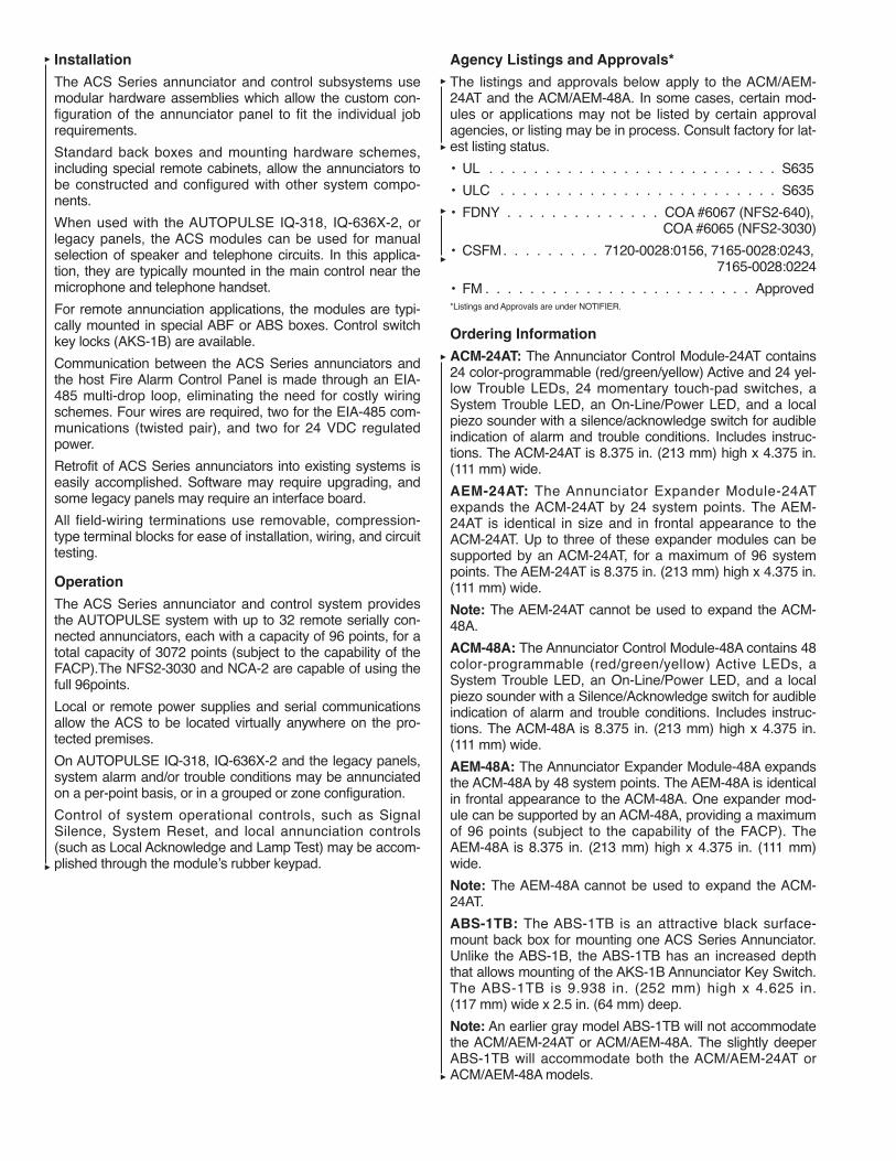
ACM-24AT: The Annunciator Control Module-24AT contains24 color-programmable (red/green/yellow) Active and 24 yel-low Trouble LEDs, 24 momentary touch-pad switches, aSystem Trouble LED, an On-Line/Power LED, and a localpiezo sounder with a silence/acknowledge switch for audibleindication of alarm and trouble conditions. Includes instruc-tions. The ACM-24AT is 8.375 in. (213 mm) high x 4.375 in.(111 mm) wide.
AEM-24AT: The Annunciator Expander Module-24ATexpands the ACM-24AT by 24 system points. The AEM-24AT is identical in size and in frontal appearance to theACM-24AT. Up to three of these expander modules can besupported by an ACM-24AT, for a maximum of 96 systempoints. The AEM-24AT is 8.375 in. (213 mm) high x 4.375 in.(111 mm) wide.
Note: The AEM-24AT cannot be used to expand the ACM-48A.
ACM-48A: The Annunciator Control Module-48A contains 48color-programmable (red/green/yellow) Active LEDs, aSystem Trouble LED, an On-Line/Power LED, and a localpiezo sounder with a Silence/Acknowledge switch for audibleindication of alarm and trouble conditions. Includes instruc-tions. The ACM-48A is 8.375 in. (213 mm) high x 4.375 in.(111 mm) wide.
AEM-48A: The Annunciator Expander Module-48A expandsthe ACM-48A by 48 system points. The AEM-48A is identicalin frontal appearance to the ACM-48A. One expander mod-ule can be supported by an ACM-48A, providing a maximumof 96 points (subject to the capability of the FACP). TheAEM-48A is 8.375 in. (213 mm) high x 4.375 in. (111 mm)wide.
Note: The AEM-48A cannot be used to expand the ACM-24AT.
ABS-1TB: The ABS-1TB is an attractive black surface-mount back box for mounting one ACS Series Annunciator.Unlike the ABS-1B, the ABS-1TB has an increased depththat allows mounting of the AKS-1B Annunciator Key Switch.The ABS-1TB is 9.938 in. (252 mm) high x 4.625 in.(117 mm) wide x 2.5 in. (64 mm) deep.
Note: An earlier gray model ABS-1TB will not accommodatethe ACM/AEM-24AT or ACM/AEM-48A. The slightly deeperABS-1TB will accommodate both the ACM/AEM-24AT orACM/AEM-48A models.

Ordering Information (Continued)
ABF-1B: The Annunciator Flush Box-1B (black) provides forthe remote mounting of a single annunciator module in aflush-mount enclosure. Knockouts are provided for use with1/2 in. (13 mm) conduit. The ABF-1B includes a paintedblack metal trim plate (11 in. (279 mm) high x 6.25 in.(159 mm) wide), mounting hardware, and an adhesive-backed annunciator label for the dress plate. The ABF-1B is9.938 in. (252 mm) high x 4.625 in. (117 mm) wide x 2.5 in.(64 mm) deep.
008917
ADP-4B: The Annunciator Dress Panel-4B (black) providesfor the cabinet mounting of one to four modules. The ADP-4Bhinge-mounts to the CAB-4 Series cabinet. Modules mountdirectly to threaded studs on the dress panel.
DP-DISP2: Dress Panel accommodates up to two annuncia-tor modules (no expanders).
BMP-1: Annunciator Blank Module is a flat black dress platethat covers unused module positions in the annunciator backbox or in the ADP-4B. The BMP-1 is 8.375 in. (213 mm) highx 4.375 in. (111 mm) wide. Studs for a variety of modulemounting options are available.
AKS-1B: The Annunciator Key Switch-1B (black) providesaccess security for the control switches on the ACM/AEM-24AT. The key switch kit includes a key and hardware formounting to the ABF-1B. Also included is an adhesive-backed annunciator label for use with the key switch/dressplate assembly.
Note: The AKS-1B can only be employed with the ABS-1TB.
Shipping WeightPart No. Description lb (kg)
432787 ACM-24AT, Annunciator 2 (0.9)Control Module, 24 ZoneAlarm/Trouble
432790 AEM-24AT, Annunciator 2 (0.9)Expander Module, 24 ZoneAlarm
432788 ACM-48A, Annunciator 2 (0.9)Control Module, 48 ZoneAlarm/Trouble
432791 AEM-48A, Annunciator 2 (0.9)Expander Module, 48 ZoneAlarm
417493 ABS-1TB, Annunciator Back 1 (0.5)Box, Surface, Single, Deep
417657 ABF-1B, Annunciator Back 1 (0.5)Box, Flush, Single
433520 ADP-4B, Annunciator Dress 2 (0.9)Panel
433614 DP-DISP2, Dress Panel 2 (0.9)
432794 BMP-1, Annunciator Blank 2 (0.9)Module
417660 AKS-1B, Annunciator Key 1 (0.5)Switch
TYCO FIRE PROTECTION PRODUCTS Copyright © 2011 Tyco Fire Protection ProductsONE STANTON STREET All rights reserved.MARINETTE, WI 54143-2542 715-735-7411 Form No. T-2007139-3


Features• Provides eight Form-C relays with 5-amp contacts
• The relays can be employed to track any group of 8 soft-ware zones in the AUTOPULSE IQ-301 control system ortrack a variety of devices and panel points, in a group fash-ion, on the IQ-318 or IQ-636X-2
• Removable terminal blocks for ease of installation and ser-vice
• DIP switch selectable memory mapping of relays
• Compatible with AUTOPULSE IQ-318 and IQ-636X-2 con-trol units
ApplicationsThe ACM-8R is a module in the ACS class of annunciatorsand will mount to an ABS-8RB annunciator surface-mountback box with blank faceplate. It provides the AUTOPULSEIQ-318 or IQ-636X-2 control system with a mappable relaycontrol module. The relays on this module can be selectedfor mapping anywhere in the AUTOPULSE IQ-318 orIQ-636X-2 (by groups of eight) control system memory map.
DescriptionCommunication between the control unit and the ACM-8R isaccomplished over a two-wire EIA-485 serial interface. Thiscommunication, to include the wiring, is supervised by theAUTOPULSE control system. Power for the annunciators isprovided via a separate power loop from the control unitwhich is inherently supervised (loss of power also results in acommunication failure at the control unit). Up to 32 annuncia-tors may be installed on an EIA-485 circuit.
ABS-8RB BACK BOX: 9 15/16 IN. x 4 5/8 IN. x 2 1/2 IN.DEEP (252 mm x 117 mm x 64 mm DEEP)
007252
Detection and Control Components
ACM-8R Relay Module (IQ-318/IQ-636X-2)
NORMALLY OPENCOMMON
NORMALLY CLOSEDNORMALLY OPEN
COMMONNORMALLY CLOSED
NORMALLY OPENCOMMON
NORMALLY CLOSEDNORMALLY OPEN
COMMONNORMALLY CLOSED
CIRCUITS CAN BEANNUNCIATED ASALARM, OR ALARM ANDTROUBLE. ALARM ANDTROUBLE CONSUMESTWO ANNUNCIATORPOINTS.
RELAY 4 {RELAY 3 {RELAY 2 {RELAY 1 {
{ RELAY 5
{ RELAY 6
{ RELAY 7
{ RELAY 8
RELAY TERMINAL ASSIGNMENTSTHE ACM-8R PROVIDES EIGHT RELAYS WITH FORM-C CONTACTS RATED FOR 5AMPS. THE TERMINAL ASSIGNMENTS ARE ILLUSTRATED BELOW.
THE ACM-8R RELAY MODULE
007253
007254
3-33

Technical Information
Voltage: . . . . . . . . . . . . . . . . . . . . . . . . . . . . . . . . . . . . 24 VDC
Standby Current: . . . . . . . . . . . . . . . . . . . . . . . . . . . . . . 30 mA
Maximum Current (all relays activated): . . . . . . . . . . . 158 mA
Data CommunicationsPort:. . . . . . . . . . . . . . . . . . . . EIA-485 operating at 20 K baud
Relay Contact RatingResistive:. . . . . . . . . . . . . . 5 amps @ 125 VAC or 30 VDCInductive: . . . . . . . . . . . . . . . . . . . . . . . 2 amps @ 125 VAC
Note: Form-C gold-plated, silver alloy relay contacts are formedium duty switching and are not intended for motorcontrol or pilot duty.
Listings and Approvals*
UL. . . . . . . . . . . . . . . . . . . . . . . . . . . . . . . . . . . . . . . . . . . S635
ULC . . . . . . . . . . . . . . . . . . . . . . . . . . . . . . . . . . . CS635 Vol. 1
MEA (NYC). . . . . . . . . . . . . . . . . . . . . . . . . . 128-07-E Vol. 5**
Factory Mutual (FM) . . . . . . . . . . . . . . . . . . . . . . . . . Approved
California State Fire Marshal (CSFM). . . . . . 7120-0028: 156
*Listings and Approvals are under NOTIFIER.
**Listing under Tyco Fire Protection Products.
Ordering Information
ShippingWeight
Part No. Description lb (kg)
417653 ACM-8R, Annunciator 2 (0.9)Control Module with 8 Relays
436996 ABS-8RB, Surface Back Box 1 (0.5)
TYCO FIRE PROTECTION PRODUCTS Copyright © 2011 Tyco Fire Protection ProductsONE STANTON STREET All rights reserved.MARINETTE, WI 54143-2542 715-735-7411 Form No. T-2007141-3

Features
• Ten addressable Class B or five addressable Class Ainitiating device circuits
• Removable 12 AWG (3.25 mm2) to 18 AWG (0.9 mm2)plug-in terminal blocks
• Status indicators for each point
• Panel-Controlled Green LED Indicators
• Unused addresses may be disabled
• Rotary address switches
• Class A or Class B operation
• FlashScan® or CLIP operation
• Mount one or two modules in a BB-XP cabinet (optional)
• Mount up to six modules on a CHS-6 chassis in a CAB-3Series or BB-25 cabinet (optional)
• Mounting hardware included
Description
The XP10-M ten-input monitor module provides an interfacebetween the addressable AUTOPULSE IQ-318 andIQ-636X-2 control units and normally open contact devices,such as pull stations, heat detectors, or flow switches.
The first address on the XP10-M is set from 01 to 150 andthe remaining modules are automatically assigned to thenext nine higher addresses. Provisions are included for dis-abling a maximum of two unused addresses.
The supervised state (normal, open, or short) of the moni-tored device is sent back to the panel. A common SLC inputis used for all modules, and the initiating device loops sharea common supervisory supply and ground – otherwise eachmonitor operates independently from the others. EachXP10-M module has panel-controlled green LED indicators.
FlashScan (U.S. Patent 5,539,389) is a communication pro-tocol that greatly enhances the speed of communicationbetween analog intelligent devices. Intelligent devices com-municate in a grouped fashion. If one of the devices withinthe group has new information, the unit’s CPU stops thegroup poll and concentrates on single points. The net effectis response speed greater than five times that of earlierdesigns.
007000
Technical Information
Standby Current: 3.5 mA (SLC current draw with alladdresses used; if some addressesare disabled, the standby currentdecreases.)
Alarm Current: 55 mA (assumes all ten LEDs solidON)
Temperature Range: 32 °F to 120 °F (0 °C to 49 °C) forUL applications; 14 °F to 131 °F(–10 °C to 55 °C) for EN54applications
Humidity Range: 10% to 85% noncondensing for ULapplications; 10% to 93% noncon-densing for EN54 applications
Dimensions:
Height: 6.8 in. (172.7 mm)
Width: 5.8 in. (147.3 mm)
Depth: 1.25 in. (31.75 mm)
Wire Gauge: 12 AWG (3.25 mm2) to 18 AWG(0.9 mm2)
Maximum SLC Wiring Resistance: 40 or 50 ohms, panel dependent
Maximum IDC Wiring Resistance: 40 ohms
Maximum IDC Voltage: 12 VDC
Maximum IDC Current: 1 mA
Detection and Control Components
XP10-M Ten-Input Monitor Module(IQ-318/IQ-636X-2)
3-34
InstallationPower-limited circuits must employ type FPL, FPLR, or FPLPcable as required by Article 760 of the NEC. The XP10-M isshipped in Class B position. Remove shunt for Class A oper-ation. Up to six XP10-M modules can be mounted on aCHS-6 chassis, which mounts in a BB-25, CAB 3 or 4, orsuitably grounded metallic cabinet. One or two modules canbe mounted in a BB-XP cabinet. Mounting hardware andinstallation instructions are provided with each module.
WiringEach XP10-M module comes with removable 12 AWG(3.25 mm2) to 18 AWG (0.9 mm2) plug-in terminal blocks.
Typical Initiating Device Circuit Configuration –Class B, Style B.Note: Any number of UL-Listed contact closure devices maybe used. DO NOT MIX fire alarm initiating and supervisorydevices on the same initiating device circuit. Install contactclosure devices per manufacturer’s installation instructions.
007001
Typical Fault-Tolerant Initiating Device CircuitConfiguration – Class A, Style D.Note: Any number of UL-Listed contact closure devices maybe used. DO NOT MIX fire alarm initiating and supervisorydevices on the same initiating device circuit. Install contactclosure devices per manufacturer’s installation instructions.
007002
Listings and Approvals*
UL . . . . . . . . . . . . . . . . . . . . . . . . . . . . . . . . . . . . . . . . . . S635
Factory Mutual (FM). . . . . . . . . . . . . . . . . . . . . . . . . Approved
California State Fire Marshal (CSFM) . . . . . . 7300-0028:219
MEA (NYC) . . . . . . . . . . . . . . . . . . . . . . . . . . . . . . . . . 43-02-E
Maryland State Fire Marshal . . . . . . . . . . . . . . . Permit #2106
USCG. . . . . . . . . . . . . . . . . . . . . . . . . . . . . . . . 161.002/A42/1
* Listings and Approvals are under NOTIFIER.
Ordering InformationShipping Weight
Part No. Description lb (kg)______ _________ ___________432714 XP10-M Ten-input 1.1 (0.5)
Monitor Module (UL)428078 BB-XP Cabinet for One 7 (3.2)
or Two Modules428079 BB-25 Cabinet 15 (6.8)428080 CHS-6 Chassis 2 (0.9)
CHS-6 CHASSIS
004754
19 IN. WIDE X 7 5/16 IN. HIGH X 2 3/16 IN. DEEP(483 mm wide x 186 mm high x 56 mm deep)
BACK-BOX/CABINET
FlashScan is a registered trademark of Honeywell International.
004755
A
B
C
Dimensions
A – Width B – Height C – Depth
BB-25 Battery 24 in 12 5/8 in 5 1/4 inBack Box (610 mm) (321 mm) (133 mm)
BB-XP 9 1/2 in 12 1/2 in 3 inCabinet (241 mm) (318 mm) (76 mm)
TYCO FIRE PROTECTION PRODUCTS Copyright © 2011 Tyco Fire Protection ProductsONE STANTON STREET All rights reserved.MARINETTE, WI 54143-2542 715-735-7411 Form No. T-2007143-3

Detection and Control Components
3-35
(Page Left Intentionally Blank)
TYCO FIRE PROTECTION PRODUCTSONE STANTON STREET Copyright © 2011 Tyco Fire Protection ProductsMARINETTE, WI 54143-2542 715-735-7411 All rights reserved.

Features
• Six addressable Form-C relay contacts
• Removable 12 AWG (3.25 mm2) to 18 AWG (0.9 mm2)plug-in terminal blocks
• Status indicators for each point
• Panel-Controlled Green LED Indicators
• Unused addresses may be disabled
• Rotary address switches
• FlashScan® or CLIP operation
• Mount one or two modules in a BB-XP cabinet (optional)
• Mount up to six modules on a CHS-6 chassis in a CAB-3Series or BB-25 cabinet (optional)
• Mounting hardware included
Description
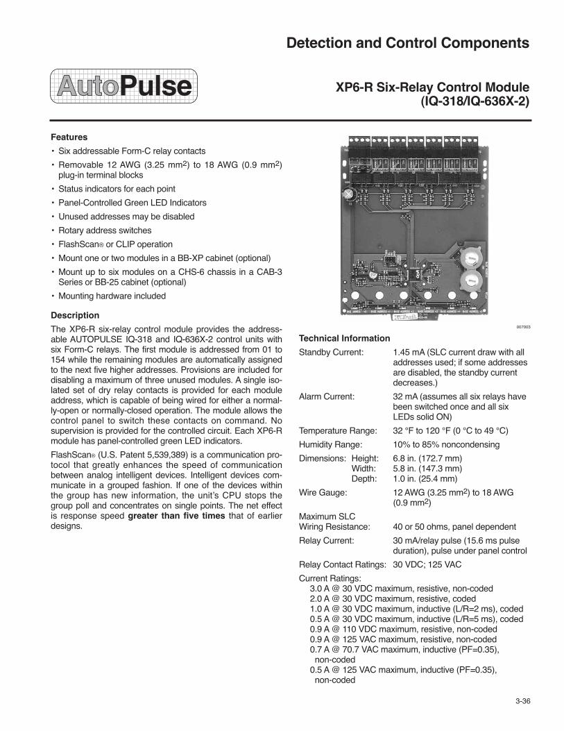
The XP6-R six-relay control module provides the address-able AUTOPULSE IQ-318 and IQ-636X-2 control units withsix Form-C relays. The first module is addressed from 01 to154 while the remaining modules are automatically assignedto the next five higher addresses. Provisions are included fordisabling a maximum of three unused modules. A single iso-lated set of dry relay contacts is provided for each moduleaddress, which is capable of being wired for either a normal-ly-open or normally-closed operation. The module allows thecontrol panel to switch these contacts on command. Nosupervision is provided for the controlled circuit. Each XP6-Rmodule has panel-controlled green LED indicators.
FlashScan® (U.S. Patent 5,539,389) is a communication pro-tocol that greatly enhances the speed of communicationbetween analog intelligent devices. Intelligent devices com-municate in a grouped fashion. If one of the devices withinthe group has new information, the unit’s CPU stops thegroup poll and concentrates on single points. The net effectis response speed greater than five times that of earlierdesigns.
007003
Technical Information
Standby Current: 1.45 mA (SLC current draw with alladdresses used; if some addressesare disabled, the standby currentdecreases.)
Alarm Current: 32 mA (assumes all six relays havebeen switched once and all sixLEDs solid ON)
Temperature Range: 32 °F to 120 °F (0 °C to 49 °C)
Humidity Range: 10% to 85% noncondensing
Dimensions: Height: 6.8 in. (172.7 mm)Width: 5.8 in. (147.3 mm)Depth: 1.0 in. (25.4 mm)
Wire Gauge: 12 AWG (3.25 mm2) to 18 AWG(0.9 mm2)
Maximum SLC Wiring Resistance: 40 or 50 ohms, panel dependent
Relay Current: 30 mA/relay pulse (15.6 ms pulseduration), pulse under panel control
Relay Contact Ratings: 30 VDC; 125 VAC
Current Ratings:3.0 A @ 30 VDC maximum, resistive, non-coded2.0 A @ 30 VDC maximum, resistive, coded1.0 A @ 30 VDC maximum, inductive (L/R=2 ms), coded0.5 A @ 30 VDC maximum, inductive (L/R=5 ms), coded0.9 A @ 110 VDC maximum, resistive, non-coded0.9 A @ 125 VAC maximum, resistive, non-coded0.7 A @ 70.7 VAC maximum, inductive (PF=0.35),non-coded
0.5 A @ 125 VAC maximum, inductive (PF=0.35),non-coded
Detection and Control Components
XP6-R Six-Relay Control Module(IQ-318/IQ-636X-2)
3-36

Installation
Up to six XP6-R modules can be mounted on a CHS-6 chas-sis, which mounts in a BB-25, CAB-A3, CAB 3 or 4 seriescabinet. One or two modules can be mounted in BB-XP cabi-net. Mounting hardware and installation instructions are pro-vided with each module.
Wiring
Each XP6-R module comes with removable 12 AWG(3.25 mm2) to 18 AWG (0.9 mm2) plug-in terminal blocks.
007004
Listings and Approvals*UL . . . . . . . . . . . . . . . . . . . . . . . . . . . S635ULC . . . . . . . . . . . . . . . . . . . . CS118 (XP6-RA)Factory Mutual (FM) . . . . . . . . . . . . . . . . ApprovedCalifornia State Fire Marshal (CSFM) . . . . 7300-0028:219MEA (NYC). . . . . . . . . . . . . . . . . . . . . 368-01-EMaryland State Fire Marshal. . . . . . . . . . Permit #2099USCG. . . . . . . . . . . . . . . . . . . . . 161.002/A42/1*Listings and Approvals are under NOTIFIER.
Ordering InformationShipping Weight
Part No. Description lb (kg)______ _________ __________432716 XP6-R Six-relay Control 1.1 (0.5)
Module (UL)428078 BB-XP Cabinet for One 7 (3.2)
or Two Modules428079 BB-25 Cabinet 15 (6.8)428080 CHS-6 Chassis 2 (0.9)
CHS-6 CHASSIS
004754
19 IN. WIDE X 7 5/16 IN. HIGH X 2 3/16 IN. DEEP(483 mm wide x 186 mm high x 56 mm deep)
BACK-BOX/CABINET
FlashScan is a registered trademark of Honeywell International.
004755
A
B
C
Dimensions
A – Width B – Height C – Depth
BB-25 Battery 24 in 12 5/8 in 5 1/4 inBack Box (610 mm) (321 mm) (133 mm)
BB-XP 9 1/2 in 12 1/2 in 3 inCabinet (241 mm) (318 mm) (76 mm)
TYCO FIRE PROTECTION PRODUCTS Copyright © 2011 Tyco Fire Protection ProductsONE STANTON STREET All rights reserved.MARINETTE, WI 54143-2542 715-735-7411 Form No. T-2007106-3

Detection and Control Components
FDM-1 Addressable Dual Monitor Module(IQ-318/IQ-636X-2)
Features
• Built-in type identification automatically identifies this deviceas a monitor module to the AUTOPULSE control unit
• Powered directly by two-wire SLC loop, no additional powerrequired
• High noise (EMF/RFI) immunity
• SEMS screws with clamping plates for ease of wiring
• Direct-dial entry of address (01-159)
• LED flashes green during normal operation (this is a pro-grammable option), and latches on steady RED to indicatealarm
• FlashScan® communication protocol
• Compatible with IQ-318 and IQ-636X-2
Applications
Use the FDM-1 module to monitor two zones of four-wiresmoke detectors, manual fire alarm pull stations, waterflowdevices, or other normally-open dry-contact alarm activationdevices. May also be used to monitor normally-open supervi-sory devices with special supervisory indication at the controlunit. Monitored circuit may be wired as an NFPA Style B only.A 47K ohm End-of-Line Resistor (provided) terminates theStyle B circuit. The FDM-1 does not support Style D (Class A)initiating device circuits. Maximum IDC loop resistance is1500 ohms.
Description
The FDM-1 is a standard-sized dual monitor module used tomonitor and supervise two independent two-wire initiatingdevice circuits (IDCs) at two separate, consecutive addressesin intelligent, two-wire systems.
Each FDM-1 uses two consecutive addresses of the 159*available module addresses on an SLC loop. It responds toregular polls from the control unit and reports its type and thestatus (open/normal/short) of its IDC. A green flashing LEDindicates that the module is in communication with the controlunit. The LED latches on steady red to indicate alarm (subjectto current limitations on the loop).
FlashScan (U.S. Patent 5,539,389) is a communication proto-col that greatly enhances the speed of communicationbetween analog intelligent devices. Intelligent devices com-municate in a grouped fashion. If one of the devices within thegroup has new information, the unit’s CPU stops the grouppoll and concentrates on single points. The net effect isresponse speed greater than five times that of earlierdesigns.
The FDM-1 automatically assigns itself to two addressablepoints, starting with the original address. For example, if theFDM-1 is set to address “56,” then it will automatically assignitself to addresses “56” and “57.” Note: “ones” addresses onthe FDM-1 are 0, 2, 4, 6, or 8 only. Terminals 6 and 7 use thefirst address, and terminals 8 and 9 use the second address.
NOTICE
Avoid duplicating addresses on thesystem.
Technical InformationNominal Operating Voltage: . . . . . . . . . . . . . . . 15 to 32 VDCMaximum Current Draw: . . . . . . . . . . . . . . . 5.7 mA (LED on)Maximum IDC Resistance: . . . . . . . . . . . . . . . . . . 1500 ohmsAverage Operating Current: . . . . . . . . 750 μA (LED flashing)EOL Resistance: . . . . . . . . . . . . . . . . . . . . . . . . . . . 47K ohmsTemperature Range: . . . . . . 32 °F to 120 °F ( 0 °C to 49 °C)Humidity Range: . . . . . . . . . . . . 10% to 93% non-condensingDimensions:
Height:. . . . . . . . . . . . . . . . . . . . . . . . . . . . 4.5 in. (114 mm)Width:. . . . . . . . . . . . . . . . . . . . . . . . . . . . . . 4 in. (102 mm)Depth: . . . . . . . . . . . . . . . . . . . . . . . . . . . 2.125 in. (54 mm)
Installation
The FDM-1 module mounts directly to a standard 4 in. square,2.124 in. (54 mm) deep, electrical box. Mounting hardwareand installation instructions are provided with each module. Allwiring must conform to applicable local codes, ordinances,and regulations. These modules are intended for power-limit-ed wiring only.
3-37

MOUNTING THE FDM-1 TO A 4 IN. (102 mm) SQUARE2 1/8 IN. (54 mm) DEEP JUNCTION BOX
004745
DETAIL OF FDM-1 – NOTE “ONES” ADDRESSESARE 0, 2, 4, 6, 8 ONLY
006882
Wiring
• Connect modules to listed compatible AUTOPULSE controlunits only.
• All wiring shown is supervised and power limited.
• Install contact closure devices per manufacturers’ installa-tion instructions.
• Any number of UL-listed contact closure devices may beused.
• DO NOT MIX fire alarm initiating, supervisory, or securitydevices on the same circuit.
Listings and Approvals*UL. . . . . . . . . . . . . . . . . . . . . . . . . . . . . . . . . . . . . . . . . . . S635ULC . . . . . . . . . . . . . . . . . . . . . . . . . . . . . . . . . . . . . . . . CS669Factory Mutual (FM). . . . . . . . . . . . . . . . . . . . . . . . . ApprovedCalifornia State Fire Marshal (CSFM) . . . . . . 7300-0028:202MEA (NYC) . . . . . . . . . . . . . . . . . . . . . . . . . . . . . . . . 143-01-EUSCG . . . . . . . . . . . . . . . . . . . . . . . . . . . . . . . . 161.002/A42/1* Listings and Approvals are under NOTIFIER.
Ordering InformationShipping Weight
Part No. Description lb (kg)
432294 FDM-1 Monitor Module 1 (0.45)
FlashScan is a registered trademark of Honeywell International.
TYPICAL DUAL TWO-WIRE STYLE B INITIATING DEVICE CIRCUIT CONFIGURATION
• ALL WIRING SHOWN IS SUPERVISEDAND POWER LIMITED.
• CONNECT MODULES TO LISTEDCOMPATIBLE CONTROL PANELS ONLY.
TWO INITIATING DEVICE CIRCUITS(L & H) EACH POWER-LIMITED TO230 μ MAX. @ 12 VDC MAX.
006883
FROM PANELOR PREVIOUSDEVICE
COMMUNICATION LINE –32 VDC MAXIMUM.SHIELDED/TWISTED-PAIRIS RECOMMENDED
TO NEXTDEVICE
47K EOLRESISTORELR-47K
47K EOLRESISTORELR-47K
TYCO FIRE PROTECTION PRODUCTS Copyright © 2011 Tyco Fire Protection ProductsONE STANTON STREET All rights reserved.MARINETTE, WI 54143-2542 715-735-7411 Form No. T-2007105-3

Detection and Control Components
FMM-101 Monitor Module (IQ-318/IQ-636X-2)
Features• Built-in type identification automatically identifies this
device as a monitor module to the AUTOPULSE controlunit
• Powered directly by two-wire FACP, no additional powerrequired
• High noise (EMF/RFI) immunity
• Tinned, stripped leads for ease of wiring
• Direct-dial entry of address (01-159)
• FlashScan™ communication protocol
Applications
Use the FMM-101 module to monitor a single device or azone of four-wire smoke detectors, manual fire alarm pull sta-tions, waterflow devices, or other normally-open dry-contactdevices. May also be used to monitor normally-open supervi-sory devices with special supervisory indication at theAUTOPULSE IQ-318 or IQ-636X-2 control unit. Monitoredcircuit/device is wired as an NFPA Style B (Class B) InitiatingDevice Circuit. A 47K ohm End-of-Line Resistor (provided)terminates the circuit.
The FMM-101 monitor module can be installed in a single-gang junction directly behind the monitored unit. Its smallsize and lightweight allow it to be installed without rigidmounting. The FMM-101 is intended for use in intelligent,two-wire systems where the individual address of each mod-ule is selected using rotary switches. It provides a two-wireinitiating device circuit for normally-open-contact fire alarmand security devices.
DescriptionThe FMM-101 is a miniature monitor module used to super-vise a Class B (Style B) circuit. Its compact design allows theFMM-101 to often be mounted in a single-gang box behindthe device it is monitoring. The FMM-101 can be used toreplace MMX-101 module (Part No. 417478) in existing sys-tems.
Each FMM-101 uses one of 159 available module addresseson an SLC loop. It responds to regular polls from the controlpanel and reports its type and the status (open/normal/short)of its Initiating Device Circuit (IDC).
FlashScan (patent pending) is a new communication protocolthat greatly enhances the speed of communication betweenanalog intelligent devices. Intelligent devices communicate ina grouped fashion. If one of the devices within the group hasnew information, the unit’s CPU stops the group poll andconcentrates on single points. The net effect is responsespeed greater than five times that of earlier designs.
Technical InformationNominal Operating Voltage:. . . . . . . . . . . . . . . . 15 to 32 VDCAverage Operating Current:. . . . . . . . . . . 350 μA (maximum)EOL Resistance: . . . . . . . . . . . . . . . . . . . . . . . . . . . 47K ohmsTemperature Range:. . . . . . . . 32 °F to 120 °F (0 °C to 49 °C)Humidity Range: . . . . . . . . . . . . 10% to 93% non-condensingWiring Length:. . . . . . . . . . . . . . . . . . 6 in. (152 mm) minimumDimensions:
High: . . . . . . . . . . . . . . . . . . . . . . . . . . . . . . 1.3 in. (33 mm)Wide: . . . . . . . . . . . . . . . . . . . . . . . . . . . . . 2.75 in. (70 mm)Deep:. . . . . . . . . . . . . . . . . . . . . . . . . . . . . . 0.5 in. (13 mm)
InstallationThe FMM-101 module should be wired and mounted withoutrigid connections inside a standard electrical box. All wiringmust conform to applicable local codes, ordinances, and reg-ulations.
Listings and Approvals*UL. . . . . . . . . . . . . . . . . . . . . . . . . . . . . . . . . . . . . . . . . S635ULC . . . . . . . . . . . . . . . . . . . . . . . . . . . . . . . . . . . . . . CS699Factory Mutual (FM) . . . . . . . . . . . . . . . . . . . . . . . ApprovedCalifornia State Fire Marshal (CSFM) . . . . . 7300-0028:202MEA . . . . . . . . . . . . . . . . . . . . . . . . . . . . . . . . . . . . 128-07-EMaryland State Fire Marshal . . . . . . . . . . . . . . Permit #2020USCG . . . . . . . . . . . . . . . . . . . . . . . . . . . . . . 161.002/A42/1* Listings and Approvals are under NOTIFIER
Ordering InformationShipping Weight
Part No. Description lb (kg)
428098 FMM-101 Monitor Module 1 (0.45)
437065 FMM-101A Monitor Module 1 (0.45)(ULC)
3-38FlashScan is a trademark of NOTIFIER.
004757
BLA
CK
VIO
LET
RE
D
YE
LLO
W
TYCO FIRE PROTECTION PRODUCTS Copyright © 2011 Tyco Fire Protection ProductsONE STANTON STREET All rights reserved.MARINETTE, WI 54143-2542 715-735-7411 Form No. T-2007101-3


Features• ALARM and TROUBLE Lamp/LED per point (IQ-318 and
IQ-636X-2) or per software zone, or more dense ALARM-only option (field selectable)
• System trouble Lamp/LED signal
• On-line/power LED indicator
• Alarm and trouble resound with flash of new conditions
• Local sounder for both alarm and trouble conditions withsilence/acknowledge switch connection
• Serial EIA-485 interface for reduced installation cost
• May be powered by 24 VDC from the unit or by remotepower supplies
• Efficient switched power converter reduces power con-sumption
• Fully supervised microprocessor-controlled electronics
• Plug-in terminal blocks for ease of installation and service
• Trouble monitor option for remote power supplies
ApplicationsThe LDM series lamp driver modules, when combined with acustom graphic display, provide annunciation and control forthe AUTOPULSE IQ-318 or IQ-636X-2 control system.These modules use a serial communications interface andmay be located up to 6,000 ft (1829 m) from the unit.
The LDM-32/LDM-E32 with a custom graphic array may beused to indicate point or software zone status. In addition, theLDM-R32 module which connects to any LDM-32 orLDM-E32 converts transistor outputs to 32 Form-A dry con-tacts for electrical isolation when interfacing the system toother equipment.
DescriptionTwo basic models are available: the LDM-32 control moduleand the LDM-E32 expander module. Each may be selectedto provide 32 alarm indications or 16 alarm and 16 trouble.Both modules mount on four standoffs inside the customannunciator graphic box. Alternately, the modules may beinstalled in a CHS-4L chassis. The CHS-4L chassis may bemounted to the graphic annunciator cabinet to provide instal-lation of up to four LDM-32 or LDM-E32 modules.
The LDM-32 includes a system trouble lamp driver and lamptest/local acknowledge switch input. Integral piezo soundersounds for each new alarm or trouble and is silenced with theLocal Acknowledge switch, or permanently disabled with adip-switch selection. Flash of new alarms or trouble is selec-table through dip switches. Switch inputs may be used forpanel Silence or Reset. Instructions are included.
One LDM-E32 is allowed per LDM-32 in alarm-only mode.Three LDM-E32 modules are allowed per LDM-32 inalarm/trouble mode. The LDM-E32 includes expander ribboncable.
The LDM-R32 provides 32 Form-A dry contacts (1 amp @ 30VDC) output terminal screw connections. It is mounted on anLDM-32 or an LDM-E32. A separate common is provided foreach group of 8 relays. Ribbon cables to connect to theLDM-32/LDM-E32 are included.
The LDM-CBL24 and LDM-CBL48 ribbon cable sets can beordered to provide either a 24 in. (610 mm) or 48 in.(1219 mm) connection between LDM-32/LDM-E32 andLEDs or lamps on a custom graphic unit. They each includeall cables necessary for one LDM-32 or LDM-E32. Cableshave a connector on one end only (split, strip, and connectother end to graphic annunciator).
Communications between the LDM series annunciators andthe host AUTOPULSE control system are made through atwo-wire EIA-485 multi-drop loop, and a two-wire regulated24 VDC power loop. Up to 32 LDM systems may be connect-ed to a single control unit, providing redundant annunciatorsif required. All field wiring terminations use removable, com-pression-type terminal blocks for ease of installation, wiring,and circuit testing.
The LDM series modules, when used with a custom graphicannunciator, provide the AUTOPULSE IQ-318 control systemwith up to 32 unique or redundant annunciators indicating thestatus of the 99 software zones. When used with theIQ-636X-2, the LDM series modules provide the system withup to 32 unique or redundant annunciators, each with acapacity of 64 points for a total capacity of 2048 points. Localor remote power supplies and serial communications allowthe custom annunciators to be located virtually anywhere onthe protected premises. Management of system operationalcontrols, such as signal silence and system reset, may beaccomplished through special key or push switches.
LDM-32 CONTROL MODULE
007255
Detection and Control Components
LDM Series Lamp Driver Modules(IQ-318/IQ-636X-2)
3-39

Description (Continued)
LDM-E32 EXPANDER MODULE
007256
LDM-R32 RELAY EXPANDER MODULE
007257
Technical Information
Size: . . . . . . . . . . . . . . . . 4.4 in. x 7.1 in. (112 mm x 181 mm)
LDM-32 and LDM-E32Output Driver: . . . . . . . . Bipolar Darlington Open Collector
NPN transistor
MaximumCurrent/Output:. . . . . . . . . . 100 mA (external current limit)
Voltage Ratingon Output Driver: . . . . . 30 VDC (either 24 VDC or 5 VDC)
LED: . . . . . . . . . . . . . . . . . . . . . . . . . . High efficiency 2 mA
LED Resistor (5 VDC):. . . . . . . . 680 Ω, 1/4 W (each LED)
LED Resistor (24 VDC): . . . . . . 10K Ω, 1/4 W (each LED)
Switch Rating: . . . . . . . . . . . . . . . . . . . . . 5 VDC @ 0.5 mA
Standby Current
LDM-32: . . . . . . . . . . . . . . . . . . . . . . . . . . . . . . . . . . 40 mA
LDM-E32: . . . . . . . . . . . . . . . . . . . . . . . . . . . . . . . . . . 2 mA
Alarm Current
LDM-32: . . . . . . . . . . . . . . . . . . . . . . . . . . . . . . . . . . 56 mA
LDM-E32: . . . . . . . . . . . . . . . . . . . . . . . . . . . . . . . . . 18 mA
LDM-R32: . . . . . . . . . . . . . . . . . . . . . . . . . . . . . . . . 288 mA
Relay Contacts – LDM-R32: . . . . 1 amp @ 30 VDC resistive,gold clad silver alloy
Listings and Approvals*
UL. . . . . . . . . . . . . . . . . . . . . . . . . . . . . . . . . . . . . . . . . . . S635
ULC . . . . . . . . . . . . . . . . . . . . . . . . . . . . . . . . . . . . . . . . CS100
MEA (NYC). . . . . . . . . . . . . . . . . . . . . . . . . 17-96-E, 317-01-E
Factory Mutual (FM) . . . . . . . . . . . . . . . . . . . . . . . . . Approved
California State Fire Marshal (CSFM) . . . . . . 7120-0028: 156
* Listings and Approvals are under NOTIFIER.
Ordering Information
ShippingWeight
Part No. Description lb (kg)
417501 LDM-32, Lamp Driver 1 (0.5)Annunciator Control Module
417502 LDM-E32, Lamp Driver 1 (0.5)Annunciator Expander Module
417650 LDM-R32, Lamp Driver 1 (0.5)Relay Module
417651 LDM-CBL24, Lamp Driver 0.5 (0.3)Annunciator Cable, 24 in.(610 mm)
417652 LDM-CBL48, Lamp Driver 0.5 (0.3)Annunciator Cable, 48 in.(1219 mm)
418576 CHS-4L, Chassis, Low Profile, 1 (0.5)For Up To 4 LDM Modules
437052 CHS-4L, Chassis, Low Profile 1 (0.5)(ULC)
CHS-4L CHASSIS13/16 IN.(21 mm)
2 1/4 IN.(57 mm)
2 1/4 IN.(57 mm)
7 IN.(178 mm)
3 IN.(76 mm)
19 IN.(483 mm)
18 3/8 IN.(467 mm)
5/16 IN.(7.9 mm)
007258
TYCO FIRE PROTECTION PRODUCTS Copyright © 2011 Tyco Fire Protection ProductsONE STANTON STREET All rights reserved.MARINETTE, WI 54143-2542 715-735-7411 Form No. T-2007138-3

Detection and Control Components
FCPS-24S6 and FCPS-24S8 6-Amp and 8-Amp24-Volt Remote Power Supplies (IQ-318/IQ-636X-2)
General
The FCPS-24S6 (6-amp) and FCPS-24S8 (8-amp) arecompact, cost-effective remote power supplies with batterycharger. The FCPS-24S6/-24S8 may be connected to any12- or 24-volt Fire Alarm Control Panel (FACP) or may beused as a stand-alone supply. Primary applications includeNotification Appliance (bell) Circuit (NAC) expansion (tosupport ADA requirements and NAC synchronization) orauxiliary power to support 24-volt system accessories. TheFCPS-24S6/-24S8 provides regulated and filtered 24 VDCpower to four notification appliance circuits configured aseither four Class B (Style Y) or Class A (Style Z, with ZNAC-4option module). Alternately, the four outputs may be config-ured as all non-resettable, all resettable, or two non-reset-table and two resettable. The FCPS-24S6/-24S8 alsocontains a battery charger capable of charging up to 18 AHbatteries.
Features
• UL-Listed NAC synchronization using System Sensor,Wheelock, or Gentex “Commander2” appliances.
• Cascadable for up to ten power supplies (four for Gentex)with strobe timing maintained.
• Operates as a “sync follower” or as a “sync generator”(default). See Note on page 2.
• Contains two fully-isolated input/control circuits – triggeredfrom FACP NAC (NAC expander mode) or jumperedpermanently “ON” (stand-alone mode).
• Four Class B (Style Y) or four Class A (Style Z, withZNAC-4 module) NACs.
• 6-amp (FCPS-24S6) or 8-amp (FCPS-24S8) full loadoutput, with 3 amps maximum/circuit, in NAC expandermode (UL 864).
• 4-amp (FCPS-24S6) or 6-amp (FCPS-24S8) continuousoutput in stand-alone mode (UL 1481).
• Compatible with coded inputs; signals passed through.
• Optional power-supervision relay (EOLR-1).
• In stand-alone mode, output power circuits may be config-ured as: resettable (reset line from FACP required), nonre-settable, or a mix of two and two.
• Fully regulated and filtered power output – optimal forpowering four-wire smoke detectors, annunciators, andother system peripherals requiring regulated/filtered power.
• Power-limiting technology meets UL power-limiting require-ments.
• Form-C normally-closed trouble relay.
• Fully supervised power supply, battery, and NACs.
• Selectable earth fault detection.
• AC trouble report selectable for immediate or 8-hour delay.
007281
• Works with virtually any UL 864 fire alarm control whichutilizes an industry-standard reverse-polarity notificationcircuit (including unfiltered and unregulated bell power).
• Requires input trigger voltage of 9.0 – 32 VDC.
• Self-contained in compact, locking cabinet – 15 in.(381 mm) high x 14.5 in. (368 mm) wide x 2.75 in. (70 mm)deep.
• Includes integral battery charger capable of charging up to18 AH batteries. Cabinet capable of housing 7.0 AHbatteries.
• Battery charger may be disabled via DIP switch for applica-tions requiring larger batteries.
• Fixed, clamp-type terminal blocks accommodate up to 12AWG (3.1 mm2) wire.
Standards and Codes
The FCPS-24S6/-24S8 complies with the following stan-dards:
• NFPA 72 National Fire Alarm Code.
• UL 864 Standard for Control Units for Fire Alarm Systems(NAC expander mode).
• UL 1481 Power Supplies for Fire Alarm Systems (stand-alone mode).
Specifications
Primary (AC) power:
• FCPS-24S6/-24S8: 120 VAC, 60 Hz, 3.2 A maximum.
• Wire size: minimum #14 AWG (2.0 mm2) with 600 Vinsulation.
3-40

Control input circuit:
• Trigger input voltage: 9 to 32 VDC.
• Trigger current: 2.0 mA (16 – 32 V). Per input: 1.0 mA(9–16 V).
Trouble contact rating: 5 amps at 24 VDC.
Auxiliary power output: specific application power 500 mAmaximum.
Output circuits:
• +24 VDC filtered, regulated.
• 3.0 amps maximum for any one circuit.
• Total continuous current for all outputs (stand-alone mode):for FCPS-24S6: 4.0 amps maximum; for FCPS-24S8:6.0 amps maximum.
• Total short-term current for all outputs (NAC expandermode): for FCPS-24S6: 6.0 amps maximum; forFCPS-24S8: 8.0 amps maximum.
Secondary power (battery) charging circuit:
• Supports lead-acid batteries only.
• Float-charge voltage: 27.6 VDC.
• Maximum charge current: 1.5 amps
• Maximum battery capacity: 18 AH.
Applications
Example 1: Expand notification appliance power an addi-tional 6.0 amps (FCPS-24S6) or 8.0 amps (FCPS-24S8).Use up to four Class B (Style Y) outputs or four Class A(Style Z) outputs (using ZNAC-4). For example, the FACPnotification appliance circuits will activate the FCPS whenreverse-polarity activation occurs. Trouble conditions on theFCPS are sensed by the FACP through the notification appli-ance circuit.
Example 2: Use the FCPS to expandauxiliary regulated 24-volt systempower up to 4.0 amps (FCPS-24S6) orup to 6.0 amps (FCPS-24S8). Bothresettable and non-resettable poweroptions are available. Resettableoutputs are created by connecting theresettable output from the FACP to oneor both of the FCPS inputs.
Example 3: Use addressable controlmodules to activate the FCPS insteadof activating it through the FACP notifi-cation appliance circuits. This typicallyallows for mounting the FCPS at greaterdistances* away from the FACP whileexpanding system architecture invarious applications.
For example, an addressable controlmodule is used to activate the FCPS,and an addressable monitor module isused to sense FCPS trouble conditions.Local auxiliary power output from theFCPS provides power to the address-able control module.
Sync Follower/Generator Note
In some installations, it is necessary to synchronize the flashtiming of all strobes in the system for ADA compliance.Strobes accomplish this by monitoring very short timingpulses on the NAC power which are created by the FACP.When installed at the end of a NAC wire run, the FCPS-24S6/-24S8 can track (i.e., “follow”) the strobe synchroniza-tion timing pulses on the existing NAC wire run. Thismaintains the overall system flash timing of the additionalstrobes attached to the FCPS.
When the FCPS-24S6/-24S8 is configured (via DIP switchsettings) as a “sync follower,” the FCPS’s NAC outputs trackthe strobe synchronization pulses present at the FCPS’ssync input terminal. The pulses originate from an upstreamFACP or other power supply.
When the FCPS-24S6/-24S8 is configured (via DIP switchsettings) as a “sync generator,” the FCPS’s sync input termi-nals are not used. Rather, the FCPS is the originator of thestrobe synchronization pulses on the FCPS’s NAC outputs.In “sync generator” mode, the sync type (System Sensor,Wheelock, or Gentex) is selectable via DIP switch settings.
Product Line Information
FCPS-24S6: 6.0 amp, 120 VAC remote charger powersupply. Includes main printed circuit board, transformers,enclosure (15 in. (381 mm) high x 14.5 in. (368 mm) wide x2.75 in. (70 mm) deep), and installation instructions (Part No.433594).
FCPS-24S8: 8.0 amp, 120 VAC remote charger powersupply. Includes main printed circuit board, transformers,enclosure (15 in. (381 mm) high x 14.5 in. (368 mm) wide x2.75 in. (70 mm) deep), and installation instructions (Part No.433595).
EOLR-1: 12/24 VDC end-of-line relay for monitoring four-wire smoke detector power.
007282

Agency Listings and Approvals*UL Listed . . . . . . . . . . . . . . . . . . . . . . . . . . . . . . . . . . . . . S635U.S. Coast Guard. . . . . . . . . . . . . . . . . . . . . . . 161.002/A42/1California State Fire Marshal. . . . . . . . . . . . . . 7315-0028:225Factory Mutual (FM) . . . . . . . . . . . . . . . . . . . . . . . . . ApprovedMEA (NYC) . . . . . . . . . . . . . . . . . . . . . . . . . . . . . . . . 299-02-E
*Listings and Approvals are under NOTIFIER.
Ordering Information
Part Shipping WeightNo. Description lb (kg)____ _________ ___________
433594 FCPS-24S6 24-Volt 18 (8.2)Remote Power Supply
433595 FCPS-24S8 24-Volt 18 (8.2)Remote Power Supply
007283
BOARD LAYOUT
TYCO FIRE PROTECTION PRODUCTS Copyright © 2011 Tyco Fire Protection ProductsONE STANTON STREET All rights reserved.MARINETTE, WI 54143-2542 715-735-7411 Form No. T-2007100-3


General
The ACPS-610 is an auxiliary power supply with a batterycharging option and a host of special features. Selectablecharging options allow the ACPS-610 to provide 6 amps ofpower to four outputs while charging batteries from 12 to 200AH, or 10 amps of power when the unit is configured for usewith an external battery charger. Four individually addressableoutputs can be independently configured for auxiliary power orNotification Appliance Circuits (NAC). NAC outputs supportnotification appliance synchronization for devices manufac-tured by System Sensor®, Wheelock, and Gentex. An optionto disable battery charging allows the system designer to usethe four built-in circuits to distribute 10 amps of power for gen-eral purposes, excluding NAC applications.
The ACPS-610 is compatible with the AUTOPULSEIQ-318/IQ-636X-2 fire suppression control panels using CLIPand FlashScan® protocol.
Features
• Listed to UL Standard 864, 9th Edition.
• Provides 6.0 A of NAC power or 10 A of general purposepower.
• Four Class B (Style Y) or four Class A (Style Z) outputs, indi-vidually addressable by the FACP.
• When built-in outputs are configured for NAC operation,each circuit supports strobe synchronization with the follow-ing manufacturers’ audio/visual devices: System Sensor(SpectrAlert® and SpectrAlert Advance Series) or Wheelockor Gentex.
• Each circuit can be software-selected for use as: aNotification Appliance Circuit, general purpose 24 VDCpower, four-wire detector power, or door holder.
• Steady, March Time (120 PPM), Two Stage, Temporal, orUZC Zone-Coded and Non-Coded devices – software-selectable by circuit.
• Universal Zone Coder (UZC-256) option supports for pro-grammable coded outputs. Up to 256 different codes.
• Charges 12 to 200 AH batteries with full supervision. Thecharger on the ACPS may be disabled via software. Whendisabled, a separate, external charger is required, for exam-ple, a CHG-120.
• May be used to provide battery backup for multiple ACPSsupplies.
• AC loss detection, brownout detection, and AC loss delayreporting.
• Power-limited outputs.
• Isolated Signaling Line Circuit (SLC) interface.
• Selectable ground fault detection.
• Canadian two stage operation.
008022
Installation Standards
The ACPS-610 complies with the following standards:
• NFPA 70 and NFPA 72 National Fire Alarm Code
• Underwriters Laboratories UL 864, 9th Edition, Standard forControl Units for Fire Alarm Systems and CAN/ULC –S527-99.
In addition, the installer should be familiar with the followingstandards:
• NEC Article 760 Fire Protective Signaling Systems
• Applicable Local and State Building Codes
• Requirements of the Local Authority Having Jurisdiction
Specifications
• Primary (AC) power:– ACPS-610: 120 VAC, 50/60 Hz input, 5.0 A maximum
• Output voltage: 24 VDC electrically regulated andpower/limited (under primary AC mains). Under secondarypower, 20.4 to 26.4 VDC.
• Output circuits – TB3, TB4, TB5, TB6 on Main Board: 1.5 Amaximum for any NAC output circuit. 2.5 A maximum for anyPower output with battery charger disabled.
• Secondary power (battery) charging circuit – TB3 onKAPS-24 Board: lead-acid battery charger which will charge12 to 200 AH batteries. Maximum charger current – 5.0 A.
• Wiring: utilizes wire sizes 12 to 18 AWG (3.1 to 0.78 mm2)
• SLC specifications: Average SLC current is 1.287 mA. SLCdata is transmitted between 24.0 VDC, 5 VDC, and 0 VDCat approximately 3.33 Kbaud.
• Battery fuse (F2): 15A, Slo-Blow.
Detection and Control Components
ACPS-610 Addressable Charger/Power Supply (IQ-318/IQ-636X-2)
3-40.1

ACPS Programming
The ACPS-610 is programmable via the simple-to-usePK-PPS programming utility, which requires a Windows® PCwith a USB port and cable. A copy of the PK-PPS program-ming utility is included with each ACPS-610. Programmingmay be performed during an on-line session with theACPS-10, or previously saved programs may be downloadedto individual ACPS-610 units. The ACPS-610 requires the useof a minimum of 5 SLC address points, and will use up to14 SLC address points to fulfill requirements for Canadiansupervision and two stage operation.
008023
Example of programming for the ACPS-610 using 6 addresses
008024
Example for ACPS-610 using Canadian reporting with Two Stage
Listings and Approvals
UL/ULC. . . . . . . . . . . . . . . . . . . . . . . . . S635
Ordering Information
ACPS-610: Addressable charger power supply, with selec-table built-in synchronization, and four built-in control mod-ules. Includes installation instructions and PK-PPS program-ming utility CD. Requires Windows PDC with USB port andUSB cable.
BB-25: The BB-25 can house one ACPS-610 and two 12 volt,26 AH batteries.
CAB-3/-4 Series: The ACPS-610 can mount in any of theCAB-3/-4 Series cabinets. This can be in the bottom of thecabinet or a tier via a CHS-PS and CHS-BH.
CHS-6: When the power supply cannot be mounted in theCAB-3/-4 Series lowest row, the ACPS-610 will require the lefttwo of the three chassis spaces.
ShippingWeight
Part No. Description lb (kg)_______ _________ __________
435807 ACPS-610 Addressable 7 (3.2)Charger/Power Supply –120 VAC
437344 ACPS-610E Addressable 7 (3.2)Charger/Power Supply –240 VAC
TYCO FIRE PROTECTION PRODUCTS Copyright © 2011 Tyco Fire Protection ProductsONE STANTON STREET All rights reserved.MARINETTE, WI 54143-2542 715-735-7411 Form No. T-2008056-3
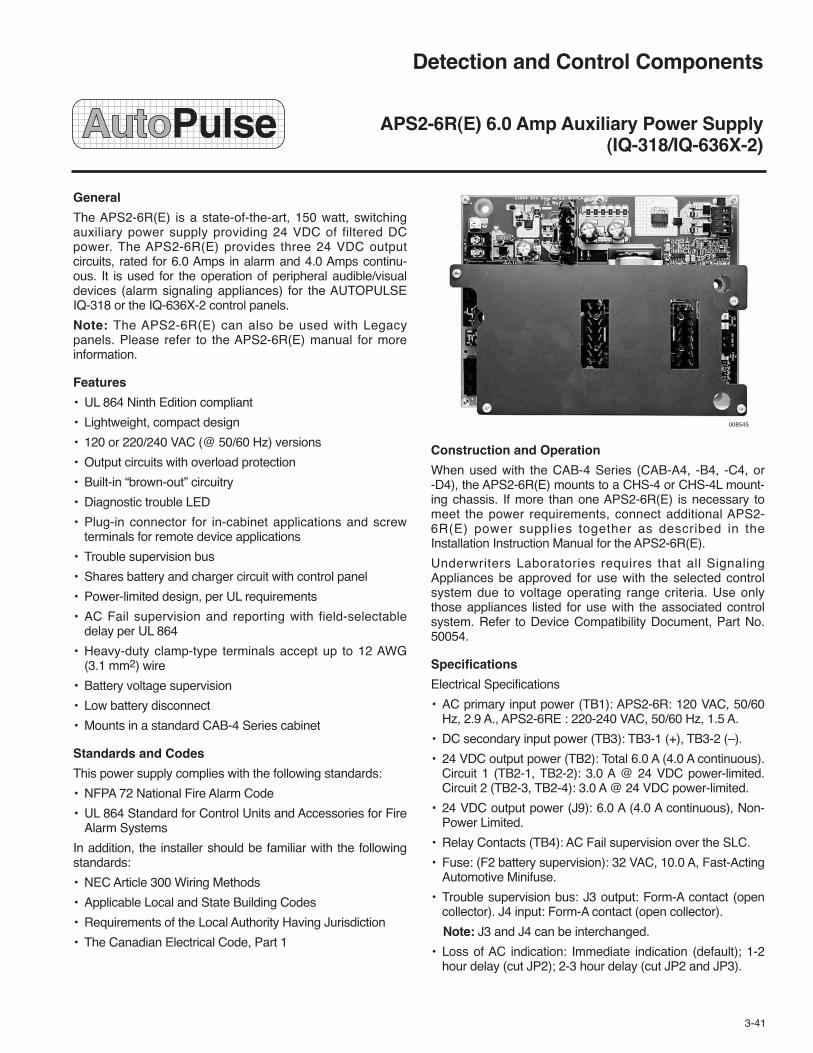
Detection and Control Components
APS2-6R(E) 6.0 Amp Auxiliary Power Supply(IQ-318/IQ-636X-2)
General
The APS2-6R(E) is a state-of-the-art, 150 watt, switchingauxiliary power supply providing 24 VDC of filtered DCpower. The APS2-6R(E) provides three 24 VDC outputcircuits, rated for 6.0 Amps in alarm and 4.0 Amps continu-ous. It is used for the operation of peripheral audible/visualdevices (alarm signaling appliances) for the AUTOPULSEIQ-318 or the IQ-636X-2 control panels.
Note: The APS2-6R(E) can also be used with Legacypanels. Please refer to the APS2-6R(E) manual for moreinformation.
Features
• UL 864 Ninth Edition compliant
• Lightweight, compact design
• 120 or 220/240 VAC (@ 50/60 Hz) versions
• Output circuits with overload protection
• Built-in “brown-out” circuitry
• Diagnostic trouble LED
• Plug-in connector for in-cabinet applications and screwterminals for remote device applications
• Trouble supervision bus
• Shares battery and charger circuit with control panel
• Power-limited design, per UL requirements
• AC Fail supervision and reporting with field-selectabledelay per UL 864
• Heavy-duty clamp-type terminals accept up to 12 AWG(3.1 mm2) wire
• Battery voltage supervision
• Low battery disconnect
• Mounts in a standard CAB-4 Series cabinet
Standards and Codes
This power supply complies with the following standards:
• NFPA 72 National Fire Alarm Code
• UL 864 Standard for Control Units and Accessories for FireAlarm Systems
In addition, the installer should be familiar with the followingstandards:
• NEC Article 300 Wiring Methods
• Applicable Local and State Building Codes
• Requirements of the Local Authority Having Jurisdiction
• The Canadian Electrical Code, Part 1
008545
Construction and Operation
When used with the CAB-4 Series (CAB-A4, -B4, -C4, or-D4), the APS2-6R(E) mounts to a CHS-4 or CHS-4L mount-ing chassis. If more than one APS2-6R(E) is necessary tomeet the power requirements, connect additional APS2-6R(E) power supplies together as described in theInstallation Instruction Manual for the APS2-6R(E).
Underwriters Laboratories requires that all SignalingAppliances be approved for use with the selected controlsystem due to voltage operating range criteria. Use onlythose appliances listed for use with the associated controlsystem. Refer to Device Compatibility Document, Part No.50054.
Specifications
Electrical Specifications
• AC primary input power (TB1): APS2-6R: 120 VAC, 50/60Hz, 2.9 A., APS2-6RE : 220-240 VAC, 50/60 Hz, 1.5 A.
• DC secondary input power (TB3): TB3-1 (+), TB3-2 (–).
• 24 VDC output power (TB2): Total 6.0 A (4.0 A continuous).Circuit 1 (TB2-1, TB2-2): 3.0 A @ 24 VDC power-limited.Circuit 2 (TB2-3, TB2-4): 3.0 A @ 24 VDC power-limited.
• 24 VDC output power (J9): 6.0 A (4.0 A continuous), Non-Power Limited.
• Relay Contacts (TB4): AC Fail supervision over the SLC.
• Fuse: (F2 battery supervision): 32 VAC, 10.0 A, Fast-ActingAutomotive Minifuse.
• Trouble supervision bus: J3 output: Form-A contact (opencollector). J4 input: Form-A contact (open collector).
Note: J3 and J4 can be interchanged.
• Loss of AC indication: Immediate indication (default); 1-2hour delay (cut JP2); 2-3 hour delay (cut JP2 and JP3).
3-41

Specifications (Continued)
Mechanical Specifications
The APS2-6R(E) measures approximately 8.63 in. (219 mm)x 6.63 in. (168 mm) x 2.38 in. (60 mm) and weighs approxi-mately 2 lb (0.91 kg).
Cabinet for Mounting
CAB-4 Series: Use CHS-4 and CHS-4L chassis for theAUTOPULSE IQ-636X-2 control panel.
Listings and Approvals*
UL Listed . . . . . . . . . . . . . . . . . . . . . . . .S635
FM . . . . . . . . . . . . . . . . . . . . . . . . .Approved
*Listings and Approvals are under NOTIFIER.
Ordering Information
ShippingWeight
Part No. Description lb (kg)_______ _________ _________436863 APS2-6R 24-Volt Filtered 2 (0.9)
Power Supply 120 VAC
436864 APS2-6RE 24-Volt Filtered 2 (0.9)Power Supply 220-240 VAC
417699 EOLR-1 12/24 VDC 1 (0.5)End-of-Line Relay
437070 EOLR-1A 12/24 VDC 1 (0.5)End-of-Line Relay (ULC)
419586 CHS-4 Four-Module Chassis 9 (4.1)
437051 CHS-4 Four-Module Chassis 9 (4.1)(ULC)
418576 CHS-4L Four-Module 1 (0.5)Chassis (Low Profile)
437052 CHS-4L Four-Module 1 (0.5)Chassis (Low Profile) (ULC)
TYCO FIRE PROTECTION PRODUCTS Copyright © 2011 Tyco Fire Protection ProductsONE STANTON STREET All rights reserved.MARINETTE, WI 54143-2542 715-735-7411 Form No. T-2009135-3

Detection and Control Components
UDACT – Universal Digital Alarm Communicator Transmitter (IQ-318/IQ-636X-2)
Features
• Dual phone lines
• Dual telephone line voltage detect
• Surface Mount Technology
• Compact in size 6 3/4 x 4 1/4 inch (172 x 108 mm)
• Built-in programmer
• Built-in 4 character red 7-segment LED display
• Manual Test Report function
• Manual Transmission Clear function
• Mounts in a separate enclosure (ABS-8RB)
• Communicates vital system status
• Annunciation of UDACT Troubles including: loss of phonelines, communication failure with either Central Station,total communication failure
• Troubleshoot Mode converts keypad to DTMF touchpad
• Individual LEDs for: Power, EIA-485 Loss, Manual Test,Kissoff, Comm Fail, Primary Line Seize, Secondary LineSeize, and Modem Communications
• Open Collector relay driver for Total CommunicationsFailure or UDACT trouble
• Real-time clock
• Extensive transient protection
• Simple EIA-485 Interface to host unit
Description
The Universal Digital Alarm Communicator Transmitter(UDACT) is designed for use on the AUTOPULSE IQ-318and AUTOPULSE IQ-636X-2 control units. It is also designedfor use on the Intelligent Network Annunciator (INA), softwarerelease 2.8 or higher. When used in conjunction with the INA,the UDACT can report the status of all control units onNOTI•FIRE•NET™. The UDACT transmits system status toUL listed Central Station Receivers via the public switchedtelephone network.
The UDACT is compact in size and may be mounted exter-nally in a separate cabinet. EIA-485 annunciator communica-tions bus and regulated 24 volt connections are required.
The UDACT is capable of transmitting the status of softwarezones (Alarm and Trouble), System Trouble, Panel Off-Normal, Supervisory, Bell Trouble, Low Battery, and AC Fail.When used with the AUTOPULSE IQ-318 and IQ-636X-2 theUDACT is capable of reporting 567 points. Reporting may bein the form of software zones (99 plus 16 special), panel cir-cuits 1-4, panel output modules 1-64, and 192 points perSLC loop (the first 96 detector and 96 module addresses).
The Universal Digital Alarm Communicator Transmitter(UDACT) provides the means to create a powerful, low cost,local area network solution for any application involving multi-ple facilities spread over a small geographic area, such ashospitals, college campuses, shopping malls, prisons, air-ports, grouped government facilities, power plants, largecommercial facilities, and much more.
3-42
TO AUTOPULSE IQ-636X-2
TO SUPERVISEDPHONE LINES SOLID
EARTHGROUND UL LISTED
PRIMARYCONTROLSTATION
(IF REQUIRED)
AUTOPULSE IQ-318
UDACT
MODEM
LOCALTELEPHONE
CENTRALOFFICE
NETWORK
BUILDING
002374 002373
UDACT IN ABS-8R (SHOWN WITH COVER REMOVED) LOCAL AREA NETWORK

The UDACT when used in the Contact ID format transmitsdetailed system status via the standard public switched tele-phone network to a digital receiver. The telephone networkbecomes the “network gateway” from the FACP to the digitalreceiver and to an optional UniNet monitor.
Contact ID is a transmission format enabling transmission ofalarm and trouble conditions on a bi-point basis. Threegroups of information are transmitted to the central station: afour-digit account code, a group number (00-99), and thedevice or zone number (000-999). Each of these three infor-mation groups is programmable. Because of the virtuallyunlimited number of combinations, the number of systems,points and/or zones transmitted is boundless.
Technical InformationStandby current: . . . . . . . . . . . . . . . . . . . . . . . . . . . . . . 40 mA
Current while communicating: . . . . . . . . . . . . . . . . . . . 75 mA
Maximum current while communicating and with open collector output activated: . . . . . . . . . . 100 mA
Voltage: . . . . . . . . . . . . . . . . . . . . . . . . . . . Regulated 24 volts
Range: . . . . . . . . . . . . . . . . . . . . . . . . . . . . . 21.2 to 28.2 volts
Required software:• IQ-301 EPROM = 73609 (or higher)• IQ-396X EPROM = #AFP4R 2.0 (or higher)• IQ-318 = All• IQ-636X = All• IQ-636X-2 = All
Listings and Approvals*
UL . . . . . . . . . . . . . . . . . . . . . . . . . . . . . . . . . . . . . . . . . . S635
ULC . . . . . . . . . . . . . . . . . . . . . . . . . . . . . . . . . CS100 Vol. VII
Factory Mutual (FM) . . . . . . . . . . . . . . . . . . . . . . . . Approved
California State Fire Marshal (CSFM) . . . . . . 7300-0028:174
MEA . . . . . . . . . . . . . . . . . . . . . . . . . . . . . . . . . . . . . 328-94-E
Industry Canada . . . . . . . . . . . . . . . . . . . . . . . . . 2132 6030 A
FCC . . . . . . . . . . . . . . . . . . . . . . . . . . . IWGUSA-20723-AL-E
* Listings and Approvals are under NOTIFIER
Ordering InformationShippingWeight
Part No. Description lb (kg)______ _________ __ ____419411 UDACT Universal Digital Alarm 2 (0.9)
COM/XMTR
436996 ABS-8RB Surface Back Box 1 (0.5)
COMPATIBILITY CHART
Osborne RadionicsSilent ITI Hoffman 8000/ Sencoa Surguard
Format # Ademco Knight CS-400 FBI Models 5800 3000R MLR-2(Addresses 16 & 42) 685 (1) 9000 (3) CP220FB 1 & 2 (5) (7) (9)
0 4+1 Ademco Express � � �
1 4+2 Ademco Express � � �(8) �
2 3+1/Standard/1800/2300 � � (2) � � (4) � � (5,6) � �
3 (Not Used)
4 3+1/Standard/1900/1400 � � (2) � (4) � � �
5 (Not Used)
6 4+1/Standard/1800/2300 � �(2) � � (4) � � (5) � �
7 (Not Used)
8 4+1/Standard/1900/1400 � � (2) � (4) � � �
9 (Not Used)
A 4+2/Standard/1800/2300 � � (2) � � (4) � � (5) � �
B (Not Used)
C 4+2/Standard/1900/1400 � � (2) � (4) � � �
D (Not Used)
E Ademco Contact ID � � � �
F (Not Used)
TYCO FIRE PROTECTION PRODUCTS Copyright © 2011 Tyco Fire Protection ProductsONE STANTON STREET All rights reserved.MARINETTE, WI 54143-2542 715-735-7411 Form No. T-2007109-3
(1) With 685-8 Line Card with Rev 4.4d software(2) With 9002 Line Card Rev 9035 software or 9032 Line Card with
9326A software(3) Rev 4.0 software.(4) FBI CP220FB Rec-11 Lin Card with Rev 2.6 software and a
memory card with Rev 3.8 software
(5) Model 6500 with Rev 600 software(6) Model 6000 with Rev 204 software(7) With Rev B control card at Rev 1.4 software and Rev C line card
at Rev 1.5 software(8) Model 2 only(9) Version 1.62 software

Detection and Control Components
3-43
(Page Left Intentionally Blank)
TYCO FIRE PROTECTION PRODUCTSONE STANTON STREET Copyright © 2011 Tyco Fire Protection ProductsMARINETTE, WI 54143-2542 715-735-7411 All rights reserved.


Features
• Charges sealed lead-acid batteries
• Automatic float-type battery charger
• Rated for batteries of 25 to 120 ampere-hours
• Obtains full float voltage within 48 hours
• For use on any 24-volt FACP which can handle the speci-fied batteries and can disable the local charger
• AC Fail delay (central station applications) per latest NFPArequirements
• Form-C Trouble contact
• Dual outputs, for easy load distribution
• Diagnostic LEDs:Primary AC OnCharger TroubleGround FaultHi ChargeLo ChargeBattery Voltage Level (3 LEDs)Low Battery
• Optional BB-55 battery cabinet
• Field-selectable input voltage, 120 VAC or 230 VAC
• Charges:25 AH batteries within 9 hours55/60 AH batteries within 20 hours120 AH batteries within 38 hours
Applications
Use the CHG-120 battery charger with the AUTOPULSE IQ-318 or IQ-636X-2 control units when batteries required forstandby are rated equal to or greater than 25 ampere-hours.Up to two batteries may be charged when either the 25AH or60AH are installed.
Description
The CHG-120 battery charger is a state-of-the-art batterycharging system designed for use with the AUTOPULSEIQ-318 or IQ-636X-2. It is designed to charge lead-acid bat-teries between 25 and 120 ampere-hours (AH).
The CHG-120 consists of a PC board and mounting chassis.Charging current is provided automatically when the batteryvoltage falls below the charger’s output voltage.
Detection and Control Components
CHG-120 Battery Charger and Meters(IQ-318/IQ-636X-2)
VOLTAGE SELECTION SWITCHFOR 115 VAC OR 230 VACOPERATION
CHG-120 BATTERY CHARGER
NINE LED STATUSINDICATORS
OPEN COLLECTOR TROUBLE DAISYCHAIN CONNECTIONS
EXTERNAL TROUBLE INPUT
FORM-C RELAY TO OTHERDEVICES
TWO OUTPUT CIRCUITS TO LOAD (POWER SUPPLY, AUXILIARY POWER SUPPLY, AMPLIFIER, ETC.)
25 AH-120 AHBATTERY CONNECTIONS
OPTIONAL AMMETER CONNECTION
15A REPLACEABLE FUSES PROVIDE SHORTCIRCUIT AND OVERLOAD PROTECTION
003575
3-44

Technical Information
Primary AC power in (TB1): . . . . . . . . . . 115 VAC, 60 Hz, 2 A230 VAC, 50 Hz, 1 A
Form-C relay (TB3): . . . . . . . . . . . . . . . . . . . . . 5 A at 30 VDC
Float charge voltage: . . . . . . . . . . . . . . . . . . . . . . . . 27.6 VDC
Maximum charging current:. . . . . . . . . . . . . . . . . . . . . . . 4.5 A
Fuses F1-F3: . . . . . . . . . . . . . . . . . . . . . . . . . . . . . . . . . . 15 A
Battery sizes: . . . . . . . . . . . . . . . . . . . . . . . . 25 AH to 120 AH
Charging time (for 2 fully discharged batteries)25 AH . . . . . . . . . . . . . . . . . . . . . . . . . . . . . . . . . . . 9 Hours55 AH/60 AH . . . . . . . . . . . . . . . . . . . . . . . . . . . . . 20 Hours120 AH . . . . . . . . . . . . . . . . . . . . . . . . . . . . . . . . . 38 Hours
High: . . . . . . . . . . . . . . . . . . . . . . . . . . . . . . 4 5/8 in. (118 mm)
Wide:. . . . . . . . . . . . . . . . . . . . . . . . . . . . . . . . . . 3 in. (76 mm)
Deep: . . . . . . . . . . . . . . . . . . . . . . . . . . . . . . 1 3/4 in. (44 mm)
Mounting Options
The CHG-120 has a variety of mounting options. It can bemounted in either a CAB-3 or CAB-4 or remotely in theBB-55 Battery Back Box. Install the CHG-120 within 20 ft(6.01 m) of the main AUTOPULSE control unit.
Mounting in CAB-3 or CAB-4 Series Backbox:The CHG-120 can be mounted in the main power supplyposition, on the lower left of the CAB-3 or CAB-4 cabinet.
Using self-tapping screws, the CHG-120 can be mountedin the lower right position (normally, where the batteriesare mounted) of the CAB-3 or CAB-4.
Remote mounting in the BB-55:The CHG-120 mounts in the left position of the cabinet.Note: Only one 60AH, 12V battery or two 25AH, 12 Vbatteries will mount with the charger board in the BB-55.
BB-55 Battery Box Battery Configurations:Without CHG-120 mounted internally:
Up to two 25AH, 12V batteriesUp to two 60AH, 12V batteries
With CHG-120 mounted internally:Up to two 25AH, 12V batteriesUp to one 60AH, 12V battery
Listings and Approvals*
UL . . . . . . . . . . . . . . . . . . . . . . . . . . . . . . . . . . . . . . . . . . S674
ULC. . . . . . . . . . . . . . . . . . . . . . . . . . . CS118/CS733 VOL. IX
Factory Mutual (FM). . . . . . . . . . . . . . . . . . . . . . . . . Approved
California State Fire Marshal (CSFM) . . . . . . 7315-0028:189
MEA (NYC) . . . . . . . . . . . . . . . . . . . . . . . . . . . . . . . . 195-97-E*Listings and Approvals are under NOTIFIER.
Ordering Information
ShippingWeight
Part No. Description lb (kg)______ _________ ________426207 CHG-120 Battery Charger 5.0 (2.3)
TYCO FIRE PROTECTION PRODUCTS Copyright © 2011 Tyco Fire Protection ProductsONE STANTON STREET All rights reserved.MARINETTE, WI 54143-2542 715-735-7411 Form No. T-2007147-3

Detection and Control Components
Annunciator Back Boxes (IQ-318/IQ-636X-2)
Description
The Annunciator back boxes are used for mounting theLCD-80, AEM, ACS, or AFM annunciator modules.
ABS-1B – The Annunciator Surface Box-1 provides for theremote mounting of a single ACM or AFM annunciator in asurface-mount enclosure. Knockouts are provided for usewith 1/2 in. conduit. The annunciator mounts directly to theABS-1B without a dress plate.
ABS-2B – The Annunciator Surface Box-2 provides for thesurface mounting of one ACM-16AT/AEM-16AT combinationor one ACM-32A/AEM-32A combination. Knockouts are pro-vided for use with 1/2 in. conduit. The annunciators mountdirectly to the ABS-2B without a dress plate.
ABF-1B – The Annunciator Flush Box-1 provides for theremote mounting of a LCD-80 or a single ACM or AFMannunciator in a flush-mount enclosure. Knockouts are pro-vided for use with 1/2 in. conduit. The ABF-1B includes apainted gray metal trim plate, mounting hardware, and anadhesive-backed Annunciator Label for the dress plate.
ABS-1TB – The ABS-1TB is an attractive surface mountback box for mounting a LCD-80 or one ACM or AFM annun-ciator.
ABS-1B AND ABS-2B SURFACE BACK BOXESABS-1B: 8 1/2 IN. (H) x 4 1/2 IN. (W) x 1 3/8 IN. (D)
(216 mm (H) x 114 mm (W) x 35 mm (D))ABS-2B: 8 1/2 IN. (H) x 8 15/16 IN. (W) x 1 3/8 IN. (D)
(216 mm (H) x 227 mm (W) x 35 mm (D))
WIDTH
HEIGHT
DEPTH
3-45
ABF-1B FLUSH BACK BOX9 15/16 IN. (H) x 4 5/8 IN. (W) x 2 1/2 IN. (D)(252 mm (H) x 117 mm (W) x 64 mm (D))
TRIMPLATE: 11 IN. (H) x 6 1/4 IN. (W)(279 mm (H) x 159 mm (W))
WIDTH
HEIGHT
HEIGHT
DEPTH
WIDTH
007372
007262
ABS-1TB SURFACE BACK BOX
2 1/2 IN.(64 mm)
9 15/16 IN.(252 mm)
4 5/8 IN.(117 mm)
007261

Technical Information
Box Type Annunciator Compatibility
ABS-1B ACM-16AT, ACM-32A, AFM-16AT, AFM-32A
ABS-2B ACM-16AT/AEM-16AT, ACM-32A/AEM-32A
ABF-1B* LCD-80, ACM-16AT, ACM-32A,AFM-16AT, AFM-32A
ABS-1TB LCD-80, AFM-16AT, AFM-32A, ACM Type withAKS-1B (key switch)
*Includes painted black metal trim plate
Approvals
UL . . . . . . . . . . . . . . . . . . . . . . . . . . . . . . . . . . . . . . . . . . S635
Ordering InformationShippingWeight
Part No. Description lb (kg)
417657 ABF-1B, Annunciator Back Box, 1 (0.45)Flush, Single
417493 ABS-1TB, Annunciator Back Box, 1 (0.45)Surface Single, Deep
417660 AKS-1B, Annunciator Key Switch 1 (0.45)
TYCO FIRE PROTECTION PRODUCTS Copyright © 2011 Tyco Fire Protection ProductsONE STANTON STREET All rights reserved.MARINETTE, WI 54143-2542 715-735-7411 Form No. T-2007140-3

General
The FDU-80G is a compact, 80 character, backlit LCD FireAnnunciator for use with the AUTOPULSE IQ-318 andIQ-636X-2 Fire Alarm Control Panels (FACPs). The FDU-80Gmimics the display of the control panel and displays completesystem point status information. Up to 32 FDU-80Gs may beconnected onto the EIA-485 Terminal Mode port of each con-trol panel. The FDU-80G requires no programming, whichsaves times during system commissioning.
The FDU-80G can be used on the same data loop as theLCD-80/LCD-80TM annunciators revision 1.6 software orhigher.
Features
• 80-character Liquid Crystal Display
• Mimics all display information from the host panel
• Control switches for System Acknowledge, Signal Silence,Drill and Reset with enable key
• System status LEDs for Power, Alarm, Trouble,Supervisory, and Alarm Silenced
• No programming necessary – FDU-80G connects to the ter-minal mode port
• Displays device type identifiers, individual point alarm, trou-ble or supervisory, zone and custom alpha labels
• Time and date display field
• Aesthetically pleasing design
• May be powered by 24 VDC from the host FACP or byremote power supplies (requires 24 VDC)
• Up to 32 FDU-80G annunciators per FACP
• Plug-in terminal blocks for ease of installation and service
• Can be remotely located up to 6,000 ft (1828.8 m) from hostcontrol panel
• Local piezo sounder with alarm and trouble resound
• Semi-flush mounts to 2.188 in. (56 mm) minimum deep,three-gang electrical box or three-gangable electricalswitchbox
• Surface mounts to SBB-3 surface backbox
007714
Operation
The FDU-80G annunciator provides the FACP with pointannunciation with full display text on an 80-character LCD dis-play. The FDU-80G also provides an array of LEDs to indicatesystem status, and also includes control switches for remotecontrol of critical system functions.
The FDU-80G provides the FACP with up to 32 remote seri-ally connected annunciators. All field-wiring terminations onthe FDU-80G use removable, compression-type terminalblocks for ease of wiring and circuit testing.
Communication between the FACP and the annunciators isaccomplished over an EIA-485 serial interface, which greatlyreduces wire and installation cost over traditional systems. Sixwires total are required: four for the EIA-485 communications(two in and two return); and two for the 24 VDC regulatedpower. Dip switches control local functions such as: piezo dis-able, control switches/key switch disable, transmit/receivemode.
Detection and Control Components
FDU-80G 80-Character Liquid Crystal Display Fire Annunciator (IQ-318/IQ-636X-2)
3-46

Listings and Approvals*
UL . . . . . . . . . . . . . . . . . . . . . . . . . . . . . . . . . . . . . . . . . . S635FM . . . . . . . . . . . . . . . . . . . . . . . . . . . . . . . . . . . . . . ApprovedCalifornia State Fire Marshal . . . . . . . . . . . . . 7120-0028:209*Listings and Approvals are under NOTIFIER.
Ordering InformationShippingWeight
Part No. Description lb (kg)_______ _________ __________435530 FDU-80G Annunciator 5.0 (2.3)
436141 SBB-3, Back Box, Surface 2.0 (0.9)
FDU-80G Terminal Mode Wiring Example
UP TO 6,000 FT (1828.8 m) BETWEENEACH DEVICE IN THE EIA-485 LOOP
UP TO 6,000 FT (1828.8 m)BACK FROM LASTDEVICE TO END OFEIA-485 LOOP
TERMINAL MODEEIA-485 (2 WIRES)
24 VDC
(2 WIRES)
TERMINAL MODEEIA-485 RETURN(2WIRES)
FDU-80G FDU-80G
FDU-80G
007716
Notes:
1. EIA-485: Maximum of 6,000 ft (1828.8 m) cable length from FACP to FDU-80G annunciators and backto FACP (6,000 ft (1828.8 m) total). Circuit is power limited.
2. Up to 32 FDU-80G annunciators may be used on the EIA-485 circuit. When multiple FDU-80Gs areused, certain panels will require additional power supplies (refer to panel documentation).
3. Between each FDU-80G annunciator are four wires: a twisted-shielded pair for data communicationsand a pair for 24 VDC power. The return circuit only requires two wires for data communication super-vision, wired from the last FDU-80G annunciator on the loop.
4. The FDU-80G annunciator can be semi-flush mounted in a three-gang electrical box with a minimumdepth of 2.188 in. (5.6 cm).
TOCONTROLPANEL
TYCO FIRE PROTECTION PRODUCTS Copyright © 2011 Tyco Fire Protection ProductsONE STANTON STREET All rights reserved.MARINETTE, WI 54143-2542 715-735-7411 Form No. T-2007163-3

Detection and Control Components
LCD2-80 Liquid Crystal Display TerminalMode Annunciator (IQ-318, IQ-636X-2)
General
The LCD2-80 is a backlit LCD annunciator for theAddressable AUTOPULSE fire suppression control panelsthat support the 80-character display format. The LCD2-80may be connected onto the four-wire EIA-485 terminal port.
The LCD2-80 mimics the display of the IQ-318 andIQ-636X-2 control panels, the NCA-2 annunciator, andlegacy panels (IQ-301, IQ-396X, and IQ-636X) thatsupported the LCD-80/LCD-80TM. Up to 32 LCD2-80 unitscan annunciate and provide remote reset, acknowledge, drilland silence of the control panel from remote locations.
Note: The LCD2-80 can be used with legacy panels thatsupported the LCD-80 terminal mode operation. Please referto the LCD2-80 manual for more information.
Features
• 80-character backlit Liquid Crystal Display (20 characters x4 lines)
• Display mimics panel or NCA annunciator– Event message– 20 characters for point label– 12 characters for extended label– Time, date, and point address
• Control switches for System Acknowledge, Signal SilenceDrill, and System Reset
• Mounts up to 6,000 ft (1828.8 m) segments between units
• Local piezo sounder with alarm/trouble resound
• Displays all analog, addressable points
• Displays device type identifiers
• Displays device and zone custom alpha labels
• Mounts to any CHS-4 chassis slot
• Slide-in label can be customized
008850
• Flush/surface/panel mount option
• No programming necessary; LCD2-80 displays time, date,and custom messages received from the compatible panelor network annunciator
• LCD2-80 is 8.25 in. (210 mm) high, 4.375 in. (111 mm)wide, and 1.75 in. (44 mm) deep
• Up to 32 LCD2-80 annunciators may be used on oneEIA-485 circuit
Note: The LCD2-80 must have sufficient regulated 24-voltpower.
008851
EIA-485(2 WIRES)
24 VDC(2 WIRES)
EIA-485 RETURN (2 WIRES)
6,000 FT (1828.8 m)MAXIMUM WIRE LENGTH BETWEEN EACH LCD2-80
IQ-318, IQ-636X-2 or NCA-2 Connecting to LCD2-80
3-46.1

Agency Listings and Approvals
These listings and approvals apply to the modules specifiedin this document. In some cases, certain modules or applica-tions may not be listed by certain approval agencies, orlisting may be in process. Consult factory for latest listingstatus.UL Listed . . . . . . . . . . . . . . . . . . . . . . . . . . . . . . . . . . . . . S635ULC Listed . . . . . . . . . . . . . . . . . . . . . . . . . . . . . . . . . . . S635FM . . . . . . . . . . . . . . . . . . . . . . . . . . . . . . . . . . . . . . ApprovedFDNY . . . . . . . . . . . . . . . . . . . . . . . . . . . . . COA# 6067, 6065CSFM . . . . . . . . . . . . . . . . 7165-0028:0243, 7165-0028-0224
Ordering Information
LCD2-80: Liquid Crystal Display Terminal Mode Annunciator.May be connected onto the four-wire EIA-485 terminal port.
ADP-4B: Annunciator dress plate, black. Allows panel mount-ing of up to four LCD2-80 modules in a CAB-4 Seriescabinet.
ABF-1B: Annunciator flush box, 9.938 in. (252 mm) high,4.625 in. (117 mm) wide, and 2.5 in. (64 mm) deep. OrderAKS-1B key switch.
ABS-1TB: Deep surface back box (mounts one LCD2-80).
AKS-1B: Key Switch (black) to enable/disable controls whenmounted in ABF-1B or ABS-1TB.
Shipping WeightPart No. Description lb (kg)_______ _________ _____________
438773 LCD2-80 Terminal 2 (0.9)Mode Annunciator
433520 ADP-4B Annunciator 1 (0.5)Dress Plate
417657 ABF-1B Annunciator 1 (0.5)Back Box, Flush, Single
417493 ABS-1TB Annunciator 1 (0.5)Back Box, Surface, Deep
417660 AKS-1B Annunciator 1 (0.5)Key Switch
TYCO FIRE PROTECTION PRODUCTS Copyright © 2011 Tyco Fire Protection ProductsONE STANTON STREET All rights reserved.MARINETTE, WI 54143-2542 715-735-7411 Form No. T-2011199

General
The NOTIFIER NCA-2 is a second-generation NetworkControl Annunciator compatible for use with AUTOPULSEIQ-318 and IQ-636X-2 fire alarm control panels, as well asfirst-generation NCA Network Control Annunciators. TheNCA-2 provides system control and display capabilities.
The NCA-2 display consists of a 640-character backlit LCDdisplay, and a control interface consisting of “soft” keys usedto navigate screen menus, “hard” keys with fixed control func-tions, and a QWERTY keypad.
Hardware Features
• Listed to UL Standard 864, 9th edition
• Full supervision of all inputs and network integrity
• Enhanced-format 640-character LCD display with back-lighting
• ACS bus for LED or graphic annunciators (EIA-485)
• Optically isolated printer interface (EIA-232)
• 11 LED status indicators: Power, Controls Active, FireAlarm, Pre-Alarm, Security, Alert, Supervisory, Trouble,Signal, Silence, CPU Failure, Point Disabled, Other Event
• Alphanumeric QWERTY rubber keypad
• Four status relays: Alarm, Trouble, Supervisory, Security(Form-C)
• Nonvolatile real-time clock can be synchronized with net-work by master node
• Optional Security Keyswitch enable Keypad functions
• Optional Security Tamper switch
• Supports up to 32 remote ACS annunciators and modules
• Requires 24 VDC and a network connection
Function Features
• Individual Enable/Disable or Group Enable/Disable local fornetworked AUTOPULSE series panels
• Lamp Test (local to NCA-2)
• History Buffer (1000 Alarm events; 4000 System events)
• Print NCA-2 programming and history reports
• Report status of panels and their respective field devices toa central station via a single UDACT
• One Master level, nine User level passwords: The Mastercan assign each User access levels (programming, alterstatus)
• Interactive Summary Event Count display, event handlingpackage
• Online programming and alter-status programs
• Intuitive user guidance program including interactive softkeys
007715
• Enhanced Read Status/Alter Status displays
• New history filters for report displaying and printing: AllEvents, Only Alarms, Only Troubles, Only Supervisory,Only, Security, Time Interval, Point Range
• Advanced/Basic Walk-Test program
• Timer control for Auto Silence, AC Fail Delay
• Meets Canadian ULC display requirements
• Environmental adjustment controls to maximize LCD legi-bility
• Meets NFPA requirements for Firefighter Smoke ControlStation (FSCS) and HVAC
NCA-2 Indicators and Controls
LED Indicators:
• Power (green) illuminates when 24 VDC power is applied;LED goes out if power is removed and NCA-2 is using abattery.
• Controls Active (green) illuminates to indicate that theNCA-2 control functions are active.
• Fire Alarm (red) illuminates when at least one fire alarmevent exists; flashes when any of these events remainunacknowledged.
• Pre-Alarm (red) illuminates when at least one pre-alarmevent exists; flashes when any of these events remainunacknowledged.
• Security (blue) illuminates when at least one security eventexists; flashes when any of these events remain unac-knowledged
Detection and Control Components
NCA-2 AUTOPULSE Series Network Control Annunciator (IQ-318/IQ-636X-2)
3-47

NCA-2 Indicators and Controls (Continued)
LED Indicators: (Continued)
• Supervisory (yellow) illuminates when at least one super-visory event exists (i.e., sprinkler valve off normal, low pres-sure, fire pump running, guard’s tour, etc.); flashes whenany of these events remain unacknowledged.
• System Trouble (yellow) illuminates when at least onetrouble event exists; flashes when any of these eventsremain unacknowledged.
• Other Event (yellow) illuminates for any category of eventnot listed above; flashes when any of these events remainunacknowledged.
• Signals Silenced (yellow) illuminates if the NCA-2 Silencekey has been pressed or if any other node sent a NetworkSilence command; flashes if only some points on a nodeare silenced.
• Point Disabled (yellow) illuminates when at least one dis-able exists on the network or in the system.
• CPU Failure (yellow) activated by the watchdog timer hard-ware, indicates an abnormal hardware or software condi-tion. Contact technical support.
Fixed Function Keys• Acknowledge
• Signal Silence
• System Reset
• Drill
• Fire Alarm Scroll/Display
• Security Scroll/Display
• Supervisory Scroll/Display
• Trouble Scroll/Display
• Other Event Scroll/Display
The five keys labeled Scroll/Display allow the user to scrollthrough messages for the particular event type. For example,pressing the Fire Alarm Scroll/Display key will scroll throughall fire alarm events, as details of each are shown in the dis-play area of the NCA-2.
Note: The Other Event Scroll/Display key also scrollsbetween Pre-Alarm and Disabled events.
• Acknowledge: Press this key to acknowledge off all activeevents.
• Signal Silence: Press this key to turn off all control mod-ules, notification appliance circuits, and panel output circuitsthat have been programmed as Silenceable.
• System Reset: Press this key to clear all latched alarmsand other events and turn off event LEDs.
• Drill Hold 2 Sec: Press this key, holding it down for twoseconds, to activate all silenceable output circuits.
Special Function Keys
• Print Screen: Press this key to print what is currently on theLCD screen.
• Lamp Test: Press this key to test the LED indicators on theleft of the keypad and to check firmware revision numbers.
• Next Selection/Previous Selection: These keys are usedwhen setting parameters in NCA-2 data fields; for example,choosing a device type as a filter for requesting a NodeHistory.
• Battery Level: Press this key to display voltage and charg-ing current level for system batteries.
Specifications
Temperature and humidity ranges: This system meets NFPArequirements for operation at 32 °F-120 °F (0 °C-49 °C) andat a relative humidity (noncondensing) of 85% at 86 °F (30 °C)per NFPA, and 93% ± 2% at 89.6 °F ± 1.1 °F (32 °C ± 2 °C)per ULC. However, the useful life of the system’s standby bat-teries and the electronic components may be adverselyaffected by extreme temperature ranges and humidity.Therefore, it is recommended that this system and all periph-erals be installed in an environment with a nominal room tem-perature of 60 °F-80 °F (15 °C-27 °C).
Electrical Requirements
The NCA-2 may be powered from a Main Power SupplyAMPS-24(E) mounted in the NCA-2 cabinet (see specifica-tions below); or from any UL Listed non-resettable 24 VDCsource from an AUTOPULSE control panel.
The battery on the NCA-2 motherboard is for RTC and SRAM;holds the history memory through power failure. Replace-ments are available.
Power source: 1) AMPS-24 (120 VAC, 50/60 Hz, 4.5 A max-imum) or AMPS-24E (240 VAC, 50/60 Hz, 2.25 A maximum)power supply; 2) the AUTOPULSE IQ-636X-2 on-boardpower supply; or 3) a supervised +24 VDC power supply thatis UL/ULC Listed for fire protective service
Total output 24 VDC power: 4.5 V in alarm.
Listings and Approvals*
These listings and approvals apply to the NCA-2. In somecases, certain modules or applications may not be listed bycertain approval agencies, or listing may be in process.Consult factory for latest listing status.
UL . . . . . . . . . . . . . . . . . . . . . . . . . . . . . . . . . . . . . . . . . . S635ULC . . . . . . . . . . . . . . . . . . . . . . . . . . . . . . . . . . . . . . . . . S635CSFM. . . . . . . . . . . . . . . . . . 7165-0028:243, 7170-0028:244MEA . . . . . . . . . . . . . . . . . . . . . . . . . . . . . . . . . . . . . 128-07-E*Listings and Approvals are under NOTIFIER.
Ordering InformationShipping Weight
Part No. Description lb (kg)_______ _________ _____________434956 NCA-2 (Network Control 5.0 (2.3)
Annunciator)
ONYX and NOTIFIER are registered trademarks of Honeywell International Inc.
TYCO FIRE PROTECTION PRODUCTS Copyright © 2011 Tyco Fire Protection ProductsONE STANTON STREET All rights reserved.MARINETTE, WI 54143-2542 715-735-7411 Form No. T-2007162-3

Detection and Control Components
VeriFire™ Tools Programming and Test Utility(IQ-318, IQ-636X-2, NCA-2)
General
VeriFire™ Tools is a programming and test utility for theAUTOPULSE IQ-318, IQ-636X-2, and NCA-2 with offline andonline capabilities that can greatly reduce installationprogramming time and increase confidence in the site-specific software. It is Windows® based and provides techno-logically advanced capabilities to aid the installer. Theinstaller may create the entire program for the control panel inthe comfort of the office, test it, store a backup file, then bringit to the site and download from a laptop into the panel.
The program includes error checks for common programmingmistakes, such as an input point that does not activate anyoutputs, or an output point that is not linked to any inputs. Inonline mode, users can perform point “read status” functions,change panel and device labels, and change detector sensi-tivities.
VeriFire™ Tools includes a compare routine, pictured at right,that can also greatly help the installer. When a new programis created, it may be compared with a previous version anddifferences are highlighted. If the program is modified fromthe panel keypad, it may be uploaded into VeriFire™ Tools,and compared with the previous version stored on disk. Theidentification of program differences greatly helps theinstaller in testing the installation. NFPA 72 requires that reac-ceptance test of a fire alarm system be performed on 100%of all points that are “known” to be modified. VeriFire™ Toolsallows the installer to determine the exact points that arechanged.
Product Line Information
433365 – VeriFire™ Tools CD-ROM. Contains programmingsoftware for the AUTOPULSE IQ-318, IQ-636X-2, andNCA-2. Includes local panel hardware connection.
432798 – VeriFire™ Tools CD-ROM contains software only.
PC Specifications (minimum requirement)
• Pentium® II 300 MHz
• 64 MB of RAM
• 50 MB of hard drive space
• Windows® 98 Second Edition, ME, NT, 2000, or XP(Windows® 95 is not supported)
• Serial port
• XGA video (1024 x 768)
VeriFire™ is a trademark of Honeywell International. Microsoft® and Windows® are registered trademarks of Microsoft Corporation. Pentium® and Intel® are registered trademarks of Intel Corporation.
3-48
TYCO FIRE PROTECTION PRODUCTS Copyright © 2011 Tyco Fire Protection ProductsONE STANTON STREET All rights reserved.MARINETTE, WI 54143-2542 715-735-7411 Form No. T-2007151-3


Detection and Control Components
SLR-24H Photoelectric/Heat Smoke Detector(IQ-318/IQ-636X-2 (with FZM))
Features• Self-restoring integral 135 °F (57 °C) heat sensor,
50 ft (15 m) rating• Low profile, 2.4 in. (60 mm) high – with base• 2 or 4 wire base compatibility, relay bases available• Highly stable operation, RF/Transient protection• Low standby current, 45μA at 24 VDC• Two built-in power/sensitivity supervision/alarm LEDs• Non-directional smoke chamber• Vandal resistant security locking feature• Built-in magnetic go/no go detector test feature• Removable smoke labyrinth for cleaning or replacement• Automatic Sensitivity window verification function meets
outlined requirements in NFPA 72, Chapter 7, Inspection,Testing and Maintenance
• Backwards compatible with SLK and SIH detectors
ApplicationsThe SLR-24H Photoelectric/Heat Smoke Detectors areintended for use in commercial, industrial, and institutionalbuildings. The detectors are placed primarily in clean, indoorenvironments where early warning fire detection is required.It is best suited for smoldering or flaming fires.
The 135 °F (57 °C) heat sensor can initiate an alarm inde-pendently. The heat detector is UL listed for 50 ft (15 m)spacing when used for evacuation alarm, if used for suppres-sion release the spacing should be reduced.
The detectors are used in combination with an AUTOPULSEControl System and a fire suppression system for automaticdetection, alarm, equipment control, and fire suppressionsystem release capabilities.
DescriptionThe SLR-24H photoelectric/heat smoke detector utilizes twobicolor LEDs for indication of status. In a normal standbycondition the LEDs flash Green every 3 seconds. When thedetector senses that its sensitivity has drifted outside the ULlisted sensitivity window, the LEDs will flash Red every 3 sec-onds. When the detector senses smoke and goes into alarm,the status LEDs will latch on Red.
The detector utilizes an infrared LED light source and siliconphoto diode receiving element in the smoke chamber. In anormal standby condition, the receiving element receives nolight from the pulsing LED light source. In the event of a fire,smoke enters the detector smoke chamber and light isreflected from the smoke particles to the receiving element.The light received is converted into an electronic signal.
Signals are processed and compared to a reference level, andwhen two consecutive signals exceeding the reference levelare received within a specified period of time, the time delaycircuit triggers the SCR switch to activate the alarm signal. Thestatus LEDs light continuously during the alarm period.
3-49
TO 4 IN. (102 mm) SQUARE OUTLET BOX
TO 3 IN. (76 mm) OR 4 IN. (102 mm) OCTAGON OUTLET BOX
DIMENSIONS – HSB-21 BASE
7/16 IN.(11 mm)
5 7/8 IN.(149 mm)
2 5/16 IN.
(59 mm)
TO 3 IN. (76 mm)OCTAGONOUTLET BOX
DIMENSIONS – NS6-224 BASE
1 1/8 IN.(29 mm)
5 7/8 IN.(149 mm)
2 15/16 IN.
(75 mm)
TO 4 IN. (102 mm)SQUARE OR 4 IN.(102 mm) OCTAGONOUTLET BOX
DIMENSIONS – HSC-224RA BASE
004624a
5/16 IN.(8 mm)
3 15/16 IN.(100 mm)
2 5/16 IN.(59 mm)
TO 4 IN. (102 mm) SQUARE OR4 IN. (102 mm) OCTAGONOUTLET BOX
DIMENSIONS – NS4-224 BASE
004630
004642
004641
9/16 IN.(14 mm)
5 7/8 IN.(149 mm)
2 3/8 IN.(60 mm)
004641
004625a
004643
004626a

Technical InformationDetector Base/Control Unit Compatibility
Detector AUTOPULSE_______________Base IQ-318, IQ-636X-2(Part No.) FZM-1
NS6-224 (427598) Yes
HSB-21 (417457) No
NS4-224 (427599) Yes
HSC-224RA (416849) No
Heat Detector: . . . . 135 °F (57 °C) self-restoring, fixed temp.
Light Source: . . . . . . . . . . . . . GaAl as infrared emitting diode
Rated Voltage: . . . . . . . . . . . . . . . . . . . . . . . 17.6 to 33.0 VDC
Working Voltage:. . . . . . . . . . . . . . . . . . . . . . . 15 to 33.0 VDC
Maximum Allowable Voltage: . . . . . . . . . . . . . . . . . . . 42 VDC
Supervisory Current:. . . . . . . . . . 45 μA maximum @ 24 VDC
Surge Current: . . . . . . . . . . . . . 160 μA maximum @ 24 VDC
Alarm Current: . . . . . . . . . . . . . 150 mA maximum @ 24 VDC
Ambient Temperature: . . . . +32 °F to +120 °F (0 °C to 49 °C)
Color: . . . . . . . . . . . . . . . . . . . . . . . . . . . . . . . . . . . Bone White
Sensitivity Test Feature: . . . . . . Automatic sensitivity windowverification test
Air Velocity:. . . . . . . . . . . . . . . . . . . . . . . . Maximum 300 FPm
Mounting Guidelines
The detector bases are designed for surface mounting. Thedetector head can be inserted or removed from the basewithout disrupting the wiring connections.
The following bases are compatible with the SLR-24HPhotoelectric/Heat Smoke Detector:
Base Type of Mounting Box
HSB-21 4 in. (102 mm) Octagon, 4 in. (102 mm)Square
NS4-224 3 in. (76 mm) OctagonNS6-224 4 in. (102 mm) Octagon, 4 in. (102 mm)
SquareHSC-224RA 4 in. (102 mm) Octagon, 4 in. (102 mm)
Square
Listings and Approvals*
UL. . . . . . . . . . . . . . . . . . . . . . . . . . . . . . . . . . . . . . . . . . S1383ULC . . . . . . . . . . . . . . . . . . . . . . . . . . . . . . . . . . . . . . . . CS463California State Fire Marshal (CSFM). . . . . . . 7272-0410:107Factory Mutual (FM) . . . . . . . . . . . . . . . . . . . . . . . . 1O5A1.AYMEA. . . . . . . . . . . . . . . . . . . . . . . . . . . . . . . . . . . . . . 284-91-E
* Listings and Approvals are under HOCHIKI AMERICA CORPORATION
Ordering InformationShipping Weight
Part No. Description lb (kg)
427597 SLR-24H Photoelectric/ 1 (0.4)Heat Smoke Detector
427598 NS6-224 Base 0.5 (0.2)
427599 NS4-224 Base 0.5 (0.2)
417457 HSB-21 Base 0.5 (0.2)
416849 HSC-224RA Relay Base 0.5 (0.2)
415730 Test Magnet 0.5 (0.2)
405491 Punk Stick (Pack of 10) 0.5 (0.2)
HSC-224RA RELAY CONTACT TERMINAL STRIP��������������������������������������������
������������������������������������������������������������������������������������������������������������������������������������������������������������������������������������������������������������������������������������������������������������������������������������������������������������������������������������������������������������������������������������������������������������������������������������������������������������������������������������������������������������������������������������������������������������
����������������������������
����������������
����������������
����������������
����������������
����������������
����������������
����������������
����������������
����������������
����������������
����������������
����������������
����������������
����������������
����������������
����������������
����������������
����������������
����������������
����������������
����������������
����������������
����������������
����������������
����������������
����������������
����������������
������������������
������������������
����������������������������������������������������������������������������������������������������������������������������������������������������������������������������������������������������������������������������������������������������������������������������������������������������������������������������������������������������������������������������������������������������������������������������������������������������������������������������������������������������������������������������������������������������������
����������������������������������
����������������
����������������
����������������
����������������
����������������
����������������
����������������
����������������
����������������
����������������
����������������
����������������
����������������
����������������
����������������
����������������
����������������
����������������
����������������
����������������
����������������
����������������
����������������
����������������
����������������
����������������
����������������
ORANGE WIRE C 1
VIOLET WIRE NC 2
YELLOW WIRE NO 3
GRAY WIRE NO 4
GREEN WIRE NC 5
BLUE WIRE C 6
TB1 CONNECTIONS
004629
WIRING DIAGRAM – HSB-21 AND HSC-224RA*STANDARD BASES, STYLE B
S2
S1S1
S2 L2
SYSTEM COMMON (DC RETURN)
*REMOTE LED (16 mA MAX) REMOTE LED
EOL RESISTOR
(+)(+)
(+)
(–) (–)(–)
(–)
L2
L3 L3L4 L4
* Do not wire HSC-224RA to remote LED as shown. Annunciation for the relay base(HSC-224RA) must be wired to the relay contacts using external power.
004628
WIRING DIAGRAM – TWO WIRE OPERATIONNS4 AND NS6 SERIES BASE
UL LISTEDCONTROL
PANEL
RESISTOR SHOWN IS FOREXAMPLE ONLY. NOT ALLANNUNCIATORS HAVE IN-LINERESISTANCE.
IN4003 DIODE MUST BEINSTALLED IN SERIESWITH THE 430 OHMRESISTOR WHEN BASEIS USED TO OPERATEREMOTE LED.
NOTE: WIRING TERMINALS FOR THE NS4AND NS6 ARE IDENTICAL. BASES WITH THE“W” SUFFIX ARE WHITE IN COLOR.
PANELPOWERSUPPLY
NEGATIVE
004627
LISTED END OFLINE DEVICE
430 OHMRESISTOR
ANNUNCIATION DEVICE MUST BECURRENT LIMITED TO 20 mA @ 24 VDCMAXIMUM. NOT LIMITING CURRENTCOULD RESULT IN DAMAGE TOTHE DETECTOR OR CAUSE ANO ALARM CONDITION.
65
3
4
TYCO FIRE PROTECTION PRODUCTS Copyright © 2011 Tyco Fire Protection ProductsONE STANTON STREET All rights reserved.MARINETTE, WI 54143-2542 715-735-7411 Form No. T-2007119-3

Detection and Control Components
SLR-24 Photoelectric Smoke Detector(IQ-318/IQ-636X-2 (with FZM))
Features
• Low profile, 1.8 in. (46 mm) high – with base
• 2 or 4 wire base compatibility, relay bases available
• Highly stable operation, RF/Transient protection
• Low standby current, 45μA at 24 VDC
• Two built-in power/sensitivity supervision/alarm LEDs
• Non-directional smoke chamber
• Vandal resistant security locking feature
• Built-in magnetic go/no go detector test feature
• Removable smoke labyrinth for cleaning or replacement
• Automatic Sensitivity window verification function meetsoutlined requirements in NFPA 72, Chapter 7, Inspection,Testing and Maintenance
• Backwards compatible with SLK and SIH detectors
Applications
The SLR-24 Photoelectric Smoke Detectors are intended foruse in commercial, industrial, and institutional buildings. Thedetectors are placed primarily in clean, indoor environmentswhere early warning fire detection is required.
The detectors are used in combination with an AUTOPULSEControl System and an fire suppression system for automaticdetection, alarm, equipment control, and fire suppressionsystem release capabilities.
Description
The SLR-24 photoelectric smoke detector utilizes two bicolorLEDs for indication of status. In a normal standby conditionthe LEDs flash Green every 3 seconds. When the detectorsenses that its sensitivity has drifted outside the UL listedsensitivity window the LEDs will flash Red every 3 seconds.When the detector senses smoke and goes into alarm thestatus LEDs will latch on Red.
The detector utilizes an infrared LED light source and siliconphoto diode receiving element in the smoke chamber. In anormal standby condition, the receiving element receives nolight from the pulsing LED light source. In the event of a fire,smoke enters the detector smoke chamber and light isreflected from the smoke particles to the receiving element.The light received is converted into an electronic signal.
Signals are processed and compared to a reference level,and when two consecutive signals exceeding the referencelevel are received within a specified period of time, the timedelay circuit triggers the SCR switch to activate the alarmsignal. The status LEDs light continuously during the alarmperiod.
3-50
5/16 IN.(8 mm)
3 15/16 IN.(100 mm)
1 7/8 IN.(47 mm)
TO 3 IN. (76 mm)OCTAGONOUTLET BOX
DIMENSIONS – NS4-224 BASE
9/16 IN.(14 mm)
5 7/8 IN.(149 mm)
1 15/16 IN.(49 mm)TO 4 IN. (102 mm) SQUARE OUTLET BOX
TO 3 IN. (76 mm) OR 4 IN. (102 mm)OCTAGON OUTLET BOX
DIMENSIONS – HSB-21 BASE
004624a 004631
1 1/8 IN.(29 mm)
5 7/8 IN.(149 mm)
2 1/2 IN.(63 mm)
TO 4 IN. (102 mm) SQUARE OR4 IN. (102 mm) OCTAGONOUTLET BOX
DIMENSIONS – HSC-224RA BASE
004633004626a
7/16 IN.(11 mm)
5 7/8 IN.(149 mm)
1 7/8 IN.(47 mm)TO 4 IN. (102 mm) SQUARE OR
4 IN. (102 mm) OCTAGONOUTLET BOX
DIMENSIONS – NS6-224 BASE
004630
004625a
004631b
004632

Technical InformationDetector Base/Control Unit Compatibility
Detector AUTOPULSE________________Base IQ-318, IQ-636X-2(Part No.) FZM-1
NS6-224 (427598) Yes
HSB-21 (417457) No
NS4-224 (427599) Yes
HSC-224RA (416849) No
Rated Voltage: . . . . . . . . . . . . . . . . . . . . . . . 17.7 to 33.0 VDCWorking Voltage:. . . . . . . . . . . . . . . . . . . . . . . 15 to 33.0 VDCSurge Current: . . . . . . . . . . . . . . . . . . . . . . 160μA @ 24 VDCNormal Current: . . . . . . . . . . . . . . . . . . . . . . 45μA @ 24 VDCAlarm Current: . . . . . . . . . . . . . 150 mA maximum @ 24 VDCAmbient Temperature: . . . . +32 °F to +120 °F (0 °C to 49 °C)Humidity: . . . . . . . . . . . . . . . . . . . . . . . . . 95% R.H. maximumColor: . . . . . . . . . . . . . . . . . . . . . . . . . . . . . . . . . . . Bone WhiteSensitivity Test Feature: . . . . . . Automatic sensitivity window
verification test
Mounting Guidelines
The detector bases are designed for surface mounting. Thedetector head can be inserted or removed from the basewithout disrupting the wiring connections.
The following bases are compatible with the SLR-24Photoelectric Detector:
Base Type of Mounting Box
HSB-21 4 in. (102 mm) Octagon, 4 in. (102 mm)Square
NS4-224 3 in. (76 mm) OctagonNS6-224 4 in. (102 mm) Octagon, 4 in. (102 mm)
SquareHSC-224RA 4 in. (102 mm) Octagon, 4 in. (102 mm)
Square
Listings and Approvals*
UL. . . . . . . . . . . . . . . . . . . . . . . . . . . . . . . . . . . . . . . . . . S1383ULC . . . . . . . . . . . . . . . . . . . . . . . . . . . . . . . . . . . . . . . . CS463California State Fire Marshal (CSFM). . . . . . . 7272-0410:107Factory Mutual (FM) . . . . . . . . . . . . . . . . . . . . . . . . 1O5A1.AYMEA. . . . . . . . . . . . . . . . . . . . . . . . . . . . . . . . . . . . . . 284-91-E
* Listings and Approvals are under HOCHIKI AMERICA CORPORATION
Ordering Information ShippingWeight
Part No. Description lb (kg)
427596 SLR-24 Photoelectric Detector 1 (0.4)
427598 NS6-224 Base 0.5 (0.2)
427599 NS4-224 Base 0.5 (0.2)
417457 HSB-21 Base 0.5 (0.2)
416849 HSC-224RA Relay Base 0.5 (0.2)
415730 Test Magnet 0.5 (0.2)
405491 Punk Stick (Pack of 10) 0.5 (0.2)
HSC-224RA RELAY CONTACT TERMINAL STRIP��������������������������������������������
������������������������������������������������������������������������������������������������������������������������������������������������������������������������������������������������������������������������������������������������������������������������������������������������������������������������������������������������������������������������������������������������������������������������������������������������������������������������������������������������������������������������������������������������������������
����������������������������
����������������
����������������
����������������
����������������
����������������
����������������
����������������
����������������
����������������
����������������
����������������
����������������
����������������
����������������
����������������
����������������
����������������
����������������
����������������
����������������
����������������
����������������
����������������
����������������
����������������
����������������
����������������
������������������
������������������
����������������������������������������������������������������������������������������������������������������������������������������������������������������������������������������������������������������������������������������������������������������������������������������������������������������������������������������������������������������������������������������������������������������������������������������������������������������������������������������������������������������������������������������������������������
����������������������������������
����������������
����������������
����������������
����������������
����������������
����������������
����������������
����������������
����������������
����������������
����������������
����������������
����������������
����������������
����������������
����������������
����������������
����������������
����������������
����������������
����������������
����������������
����������������
����������������
����������������
����������������
����������������
ORANGE WIRE C 1
VIOLET WIRE NC 2
YELLOW WIRE NO 3
GRAY WIRE NO 4
GREEN WIRE NC 5
BLUE WIRE C 6
TB1 CONNECTIONS
004629
WIRING DIAGRAM – HSB-21 AND HSC-224RA*STANDARD BASES, STYLE B
S2
S1S1
S2 L2
SYSTEM COMMON (DC RETURN)
*REMOTE LED (16 mA MAX) REMOTE LED
EOL RESISTOR
(+)(+)
(+)
(–) (–)(–)
(–)
L2
L3 L3L4 L4
* Do not wire HSC-224RA to remote LED as shown. Annunciation for the relay base(HSC-224RA) must be wired to the relay contacts using external power.
004628
WIRING DIAGRAM – TWO WIRE OPERATIONNS4 AND NS6 SERIES BASE
UL LISTEDCONTROL
PANEL
RESISTOR SHOWN IS FOREXAMPLE ONLY. NOT ALLANNUNCIATORS HAVE IN-LINERESISTANCE.
IN4003 DIODE MUST BEINSTALLED IN SERIESWITH THE 430 OHMRESISTOR WHEN BASEIS USED TO OPERATEREMOTE LED.
NOTE: WIRING TERMINALS FOR THE NS4AND NS6 ARE IDENTICAL. BASES WITH THE“W” SUFFIX ARE WHITE IN COLOR.
PANELPOWERSUPPLY
NEGATIVE
004627
LISTED END OFLINE DEVICE
430 OHMRESISTOR
ANNUNCIATION DEVICE MUST BECURRENT LIMITED TO 20 mA @ 24 VDCMAXIMUM. NOT LIMITING CURRENTCOULD RESULT IN DAMAGE TOTHE DETECTOR OR CAUSE ANO ALARM CONDITION.
65
3
4
TYCO FIRE PROTECTION PRODUCTS Copyright © 2011 Tyco Fire Protection ProductsONE STANTON STREET All rights reserved.MARINETTE, WI 54143-2542 715-735-7411 Form No. T-2007118-3
Detection and Control Components
3-51
(Page Left Intentionally Blank)
TYCO FIRE PROTECTION PRODUCTSONE STANTON STREET Copyright © 2011 Tyco Fire Protection ProductsMARINETTE, WI 54143-2542 715-735-7411 All rights reserved.

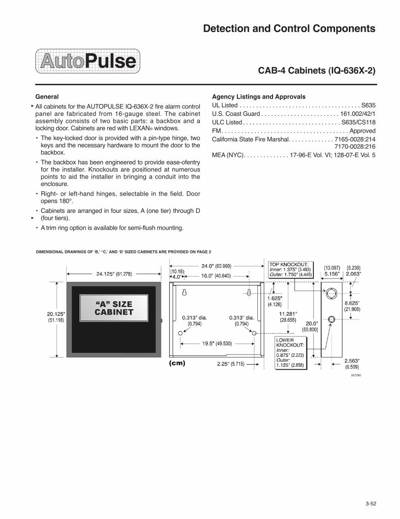
Detection and Control Components
CAB-4 Cabinets (IQ-636X-2)
General
All cabinets for the AUTOPULSE IQ-636X-2 fire alarm controlpanel are fabricated from 16-gauge steel. The cabinetassembly consists of two basic parts: a backbox and alocking door. Cabinets are red with LEXAN® windows.
• The key-locked door is provided with a pin-type hinge, twokeys and the necessary hardware to mount the door to thebackbox.
• The backbox has been engineered to provide ease-ofentryfor the installer. Knockouts are positioned at numerouspoints to aid the installer in bringing a conduit into theenclosure.
• Right- or left-hand hinges, selectable in the field. Dooropens 180°.
• Cabinets are arranged in four sizes, A (one tier) through D(four tiers).
• A trim ring option is available for semi-flush mounting.
Agency Listings and ApprovalsUL Listed . . . . . . . . . . . . . . . . . . . . . . . . . . . . . . . . . . . . . S635U.S. Coast Guard . . . . . . . . . . . . . . . . . . . . . . . . 161.002/42/1ULC Listed . . . . . . . . . . . . . . . . . . . . . . . . . . . . . . S635/CS118FM. . . . . . . . . . . . . . . . . . . . . . . . . . . . . . . . . . . . . . . ApprovedCalifornia State Fire Marshal. . . . . . . . . . . . . . 7165-0028:214
7170-0028:216MEA (NYC). . . . . . . . . . . . . . 17-96-E Vol. VI; 128-07-E Vol. 5
007290
DIMENSIONAL DRAWINGS OF ‘B,’ “C,’ AND ‘D’ SIZED CABINETS ARE PROVIDED ON PAGE 2
3-52

007291

Ordering Information
A complete cabinet assembly consists of: a door, a backbox,an optional battery plate, and an optional semi-flush trim ring.For each cabinet required, order one “DR” door and one“SBB” backbox. The BP-4 battery plate is required for eachcabinet assembly that mounts batteries and/or a powersupply in the lower position of the cabinet. The optional trimring is an attractive “picture frame”-style black metal ring.
One Tier, “A” Size:
Part No. 435598 DR-A4R: Door assembly, LEXAN window,one tier, RED. (ULC Part No. 437039)
Part No. 433526 SBB-A4R: Backbox assembly, one tier,RED. (ULC Part No. 437043)
Part No. 433534 TR-A4: Accessory semi-flush-mount trimring, one tier (opening 24.062 in. (611 mm) W x 20.062 in.(510 mm) H), BLACK. Note: Black trim rings are used withred cabinets. (ULC Part No. 437047)
Part No. 432795 BP-4: Battery panel. Used to cover batteryand power supply when lower position is used in backbox.
Two Tiers, “B” Size:
Part No. 435599 DR-B4R: Door assembly, LEXAN window,two tiers, RED. (ULC Part No. 437040)
Part No. 433527 SBB-B4R: Backbox assembly, two tiers,RED. (ULC Part No. 437044)
Part No. 433535 TR-B4: Accessory semi-flush-mount trimring, two tiers (opening 24.062 in. (611 mm) W x 28.562 in.(725 mm) H), BLACK. Note: Black trim rings are used withred cabinets. (ULC Part No. 437048)
Part No. 432795 BP-4: Battery panel. Used to cover batteryand power supply when lower position is used in backbox.
Three Tiers, “C” Size:
Part No. 435600 DR-C4R: Door assembly, LEXAN window,three tiers, RED. (ULC Part No. 437041)
Part No. 433529 SBB-C4R: Backbox assembly, three tiers,RED. (ULC Part No. 437045)
Part No. 433589 TR-C4: Accessory semi-flush-mount trimring, three tiers (opening 24.062 in. (611 mm) W x 37.187 in.(945 mm) H), BLACK. Note: Black trim rings are used withred cabinets. (ULC Part No. 437049)
Part No. 432795 BP-4: Battery panel. Used to cover batteryand power supply when lower position is used in backbox.
Four Tiers, “D” Size:
Part No. 435601 DR-D4R: Door assembly, LEXAN window,four tiers, RED. (ULC Part No. 437042)
Part No. 433532 SBB-D4R: Backbox assembly, four tiers,RED. (ULC Part No. 437046)
Part No. 433590 TR-D4: Accessory semi-flush-mount trimring, four tiers (opening 24.062 in. (611 mm) W x 45.812 in.(1164 mm) H), BLACK. Note: Black trim rings are used withred cabinets. (ULC Part No. 437050)
Part No. 432795 BP-4: Battery panel. Used to cover batteryand power supply when lower position is used in backbox.
Accessories:
Part No. 433521 DP-1B: Blank dress panel, covers oneCAB-4 tier, BLACK. (ULC Part No. 437058)
Agency Listings and Approvals
See the first page of this data sheet for listing agencies andfile numbers. These listings and approvals apply to theCAB-4 Series Cabinets. In some cases, certain modules orapplications may not be listed by certain approval agencies,or listing may be in process. Consult factory for latest listingstatus.
LEXAN® is a registered trademark of GE Plastics, a subsidiary of General Electric Company.
007292
THE BP-4 BATTERY DRESS PANEL COVERS THE MAIN POWER SUPPLYAND THE BATTERIES IN THE CABINET.
ONLY ONE BP-4 IS REQUIRED PER CABINET.
TYCO FIRE PROTECTION PRODUCTS Copyright © 2011 Tyco Fire Protection ProductsONE STANTON STREET All rights reserved.MARINETTE, WI 54143-2542 715-735-7411 Form No. T-2007160-3


Detection and Control Components
LEM-320 Loop Expander Module (IQ-636X-2)
General
The LEM-320 module is used to expand the AUTOPULSEIQ-636X-2 to a second signaling line circuit (SLC) loop.
Features
• Up to 12,500 ft (3,810 m) on a Class B (Style 4) SLC loop(twisted unshielded)
• Built-in degraded mode increases survivability
• Very simple installation — plug-in style
Specifications
• Voltage: 24 VDC nominal, 27.6 VDC maximum
• Maximum loop length: The maximum wiring distance ofan SLC using 12 AWG (3.1 mm2) twisted-pair wire is12,500 ft (3810 m) per channel. For a twisted unshieldedpair, 12 AWG (3.1 mm2) to 18 AWG (0.78 mm2).Distance with 12 AWG: 12,500 ft (3,810 m)Distance with 14 AWG: 8,000 ft (2,438 m)Distance with 16 AWG: 4,875 ft (1,486 m)Distance with 18 AWG: 3,225 ft (983 m)50 ohms maximum per length of Style 6 and 7 loops50 ohms maximum per branch for Style 4 loop
• Maximum current: for LEM-320: 100 mA; for single SLCloop: 400 mA maximum*
*Note: Maximum short circuit — circuit will shut down untilshort-circuit condition is corrected.
• Maximum resistance: 50 ohms (supervised and power-limited)
• Temperature and humidity ranges: This system meetsNFPA requirements for operation at 32 °F to 120 °F (0 °Cto 49 °C); and at a relative humidity (noncondensing) of85% at 86 °F (30 °C) per NFPA, and 93% ± 2% at 89.6 °F± 1.1 °F (32 °C ± 2 °C) per ULC. However, the useful life ofthe system’s standby batteries and the electronic compo-nents may be adversely affected by extreme temperatureranges and humidity. Therefore, it is recommended that thissystem and all peripherals be installed in an environmentwith a nominal room temperature of 60 °F to 80 °F (15 °Cto 27 °C).
Listings and ApprovalsUL Listed . . . . . . . . . . . . . . . . . . . . . . . . . . . . . . . . . . . . . S635ULC Listed . . . . . . . . . . . . . . . . . . . . . . . . . . . . . . S635/CS118California State Fire Marshal. . . . . . . . . . . . . . . 7170-0028.26FM. . . . . . . . . . . . . . . . . . . . . . . . . . . . . . . . . . . . . . . ApprovedMEA (NYC) . . . . . . . . . . . . . . . . . . . . . . . . . . . 128-07-E Vol. 5City of DenverHong Kong
Product Line Information
LEM-320 Loop Expander Module. Expands AUTOPULSEIQ-636X-2 to two loops.
007219
3-53

FlashScan is a registered trademark of Honeywell International.
Installation
Mount LEM-320 module within the cabinet with the CPU;standard mounting locations are adjacent to the panel or inthe row immediately below it. See panel installation manualsfor instructions on installing modules and/or option boards inthe chassis.
After the LEM-320 module is mounted in the cabinet, con-nect the SLC loop to TB1. Up to 159 detectors and 159 mod-ules can be connected to the SLC loop. FlashScan® devicescan operate in either FlashScan or CLIP mode, but CLIPdevices in CLIP mode must be set to address 99 or lower.
Ordering Information
Part Shipping WeightNo. Description lb (kg)____ _________ ___________
433508 LEM-320 Loop Expander 1 (0.45)Module
437062 LEM-320 Loop Expander 1 (0.45)Module (ULC)
J1 – CONNECTS TO J3ON IQ-636X CPU BOARD
GROUND FAULT LED
SLC LOOP CONNECTION TB1
007220
LEM-320 LOOP EXPANDER MODULE
TYCO FIRE PROTECTION PRODUCTS Copyright © 2011 Tyco Fire Protection ProductsONE STANTON STREET All rights reserved.MARINETTE, WI 54143-2542 715-735-7411 Form No. T-2007107-3

Features
• Plug-in detector line – mounting base included.
• Large wire-entry port.
• In-line terminals with SEMS screws.
• Mounts to octagonal and single-gang backboxes, 4 in.(102 mm) square backboxes, or directly to ceiling.
• Stop-Drop ‘N Lock™ attachment to base.
• Removable detector cover and chamber for easy cleaning.
• Built-in remote maintenance signaling.
• Drift compensation and smoothing algorithms.
• Simplified sensitivity measurement.
• Wide-angle, dual-color LED indication.
• Loop testing via “EZ Walk” feature.
• Built-in test switch.
Description
New Series photoelectric and photoelectric/ thermal smokedetectors represent a significant advancement in conventionaldetection, incorporating three key features: installation ease,intelligence, and instant inspection.
Installation ease: The New Series redefines installation easewith its plug-in design. This allows an installer to pre-wire thebases included with the heads. The large wire-entry port andin-line terminals provide ample room for neatly routing thewiring inside the base. The base accommodates a variety ofbackbox mounting methods, as well as direct mounting withdrywall anchors. To complete the installation, New Seriesheads plug into the base with a simple Stop-Drop ’N Lockaction.
Intelligence: New Series detectors offer a number of intelli-gent features to simplify testing and maintenance. Driftcompensation and smoothing algorithms, to minimizenuisance alarms, are standard in the New Series. Whenconnected to an AUTOPULSE 542R/542D Control Panel,two-wire New Series detectors are capable of generating aremote maintenance signal when they need cleaning. Thissignal is indicated by LEDs located at the AUTOPULSE542R/542D Control Panel.
Instant inspection: The New Series provides wide-angle redand green LED indicators for instant inspection of detectorcondition. The LEDs indicate: normal standby, out-of-sensitiv-ity, alarm, or freeze trouble conditions. The “EZ Walk” loop testfeature is available on two-wire New Series detectors whenconnected to an AUTOPULSE 542R/542D Control Panel. The“EZ Walk” feature verifies the initiating loop wiring by provid-ing LED status indication at each detector.
008037
Physical Specifications
Operating Temperature Range: For models 2W-B and 4WB:32 °F to 120 °F (0 °C to 49 °C); for thermal models 2WT-B and4WT-B: 32 °F to 100 °F (0 °C to 38 °C).
Storage Temperature Range: –4 °F to +158 °F (–20 °C to+70 °C).
Operating Humidity Range: 10% – 95% RH, non-condens-ing.
Thermal Sensor: 135 °F (57 °C) fixed (models 2WT-B,4WT-B).
Freeze Trouble: 41 °F (5 °C) (models 2WT-B and 4WT-B).
Sensitivity: 2.5%/ft (0.762%/meter) nominal.
Input Terminals: Utilize 14 to 22 AWG wire.
Dimensions (including base): 5.3 in. (135 mm) diameter,2.0 in. (51 mm) high.
Weight: 6.3 oz (178.6 grams).
Mounting Options: 3.5 in. (89 mm) octagonal backbox; 4 in.(102 mm) octagonal backbox; single-gang backbox; 4 in.(102 mm) square backbox with a plaster ring; or direct mountto ceiling.
Detection and Control Components
New Series Photoelectric and Photoelectric/Thermal Smoke Detectors (542R/542D)
3-54

Electrical Specifications
Operating Voltage: 12/24 V non-polarized nominal; 8.5 Vminimum; 35 V maximum.
Maximum Ripple Voltage: 30% of nominal (peak to peak).
Standby Current: 50 μA maximum average. Peak standbycurrent: for two-wire models: 100 μA; not applicable for four-wire models.
Maximum Start-Up Capacitance: For two-wire models:0.1 μF; not applicable for four-wire models.
Latching Alarm: Reset by momentary power interruption.
Maximum Initial Start-Up Time: For two-wire models: 45seconds; for four-wire models: 15 seconds.
Maximum Alarm Current: For two-wire models: 130 mAlimited by control panel; For four-wire models: 20 mA @ 12 V,23 mA @ 24 V.
Alarm Contact Ratings: For four-wire models: 0.5 A @ 30VAC/VDC; not applicable for two-wire models.
Alarm Reset Voltage: 2.5 V.
Alarm Reset Time: 0.3 seconds.
Wiring Diagrams
008038
Agency Listings and ApprovalsUL Listed . . . . . . . . . . . . . . . . . . . . . . . . S911
FM . . . . . . . . . . . . . . . . . . . . . . . . . Approved
CSFM . . . . . . . . . . . . . . . . . . . . 7272-1653:152
MEA . . . . . . . . . . . . . . . . . . . . . . . . 290-01-E
Maryland State Fire Marshal . . . . . . . . Permit No. 2093
ETL . . . . . . . . . . . . . . . . . . . . . . . . Approved
USCG. . . . . . . . . . . . . . . . . . . . . 161.002/A42/1
Ordering InformationShippingWeight
Part No. Description lb (kg)_______ _________ _________435893 2W-B: Two-Wire 1.5 (0.7)
Photoelectric Smoke Detector
435894 2WT-B: Two-Wire 1.5 (0.7)Photoelectric Smoke Detectorwith 135 °F (57 °C)Fixed Thermal Sensor
435895 4W-B: Four-Wire 1.5 (0.7)Photoelectric Smoke Detector
435896 4WT-B: Four-Wire 1.5 (0.7)Photoelectric Smoke Detectorwith 135 °F (57 °C)Fixed Thermal Sensor
4W-B or 4WT-BDETECTOR
(5) CO
M(4) N
O(3) – IN
/OU
T(2) +
OU
T(1) +
IN
(5) CO
M(4) N
O(3) – IN
/OU
T(2) +
OU
T(1) +
IN
+–
AUX orSMOKEPOWER
4-WIRECONTROLPANEL
+–IDC
EOLRESISTOR
EOL RELAYEOLR-1
Stop-Drop ‘N Lock™ is a trademark of Honeywell International Inc.
LED Modes Green LED Red LED
Power Up Blink every Blink every10 seconds 10 seconds
Normal (Standby) Blink every OFF5 seconds
Out of Sensitivity OFF Blink every5 seconds
Freeze Trouble OFF Blink every10 seconds
Alarm OFF Solid ON
Power Up Sequence for LED Indication
Condition Duration
Initial LED 80 SecondsStatus Indication
Initial LED 4 MinutesStatus Indication (ifexcessive electricalnoise is present)
ANN-BUS
TYCO FIRE PROTECTION PRODUCTS Copyright © 2011 Tyco Fire Protection ProductsONE STANTON STREET All rights reserved.MARINETTE, WI 54143-2542 715-735-7411 Form No. T-2008081-3

Detection and Control Components
2151 Photoelectric Smoke Detector (542R/542D)
Features
• Unique optical sensing chamber
• Built-in signal processing
• 3.0% nominal sensitivity
• Removable cover for field cleaning
• Visible LED “blinks” in standby
• Sealed against dirt, insects, and back pressure
• Field metering of detector sensitivity
• Built-in magnetic test switch
• Low standby current
• Built-in tamper-resistant feature
• Designed for direct surface or electrical box mounting
• 360° Field viewing angle of the visual alarm LEDs
• Insect-resistant screening
• Easy plug-in of the head to base
• SEMS screws for easy wiring
• Air velocity up to 3000 feet per minute (914 meters perminute)
Applications
Photoelectric detectors are recommended in areas whereslow smoldering fires are likely to ignite. In areas where smallcombustion particles are usually present from fork-lift trucks,cooking stoves, etc., they are less likely than ionizationdetectors to produce false alarms. The detectors are used incombination with an AUTOPULSE Control System and anfire suppression system for automatic detection, alarm,equipment control, and fire suppression system releasecapabilities.
Description
The 2151 photoelectric smoke detector contains a uniqueoptical sensing chamber designed to sense the presence ofsmoke particles produced by a wide range of combustionsources and meet the performance criteria designed by UL268. An integrated circuit incorporates signal processing toreduce false alarms and sample/hold circuitry to provide easyfield metering of sensitivity.
The 2151 photoelectric detector incorporates the light scatterprinciple within its sensing chamber and solid-state circuitryallowing it to react to either smoldering or flaming fires.
The high-impedance circuitry of the detector allows a singleloop to power multiple detectors with very low power con-sumption. Two externally-mounted LED indicators are provid-ed which will blink as long as the detector is powered and willlight steadily when the detector is in alarm.
Technical Information
Stand-by Current: . . . . . . . . . . . . . . . . . . . . . . . 85 microamps
Sensitivity: . . . . . . . . . . . . . . . . . . . . . . . . . . . . . 3.0% nominal
Weight: . . . . . . . . . . . . . . . . . . . . . . . . . . . . . . . . 0.5 lb (277 g)
Size:. . . . . . . . . . . . . . . . . . . . . . 1.7 in. high x 4.0 in. diameter(84 mm x 102 mm)
Construction:. . . . . . . . . Flame retardant white thermo plastic
Temperature: . . . . . . . . . . . . . 32 °F to 120 °F (0 °C to 49 °C)
Humidity Range: . . . . . . . . . . . 10-93% RH (non-condensing)
Maximum Air Velocity: . . . . . . . . . . . . . . . . 3000 ft per minute(15 m per second)
3-55
B110LP OPTIONAL NFPA CLASS “A” WIRING
3
(+)(+)
4
2
13
2
1
4
(+) (+)
(+)(+)
(–)
(–)(–)
(–) (–)
2151 PHOTOELECTRIC SMOKE DETECTOR WITH BASE
007353
007350

Mounting Guidelines
The detector bases are designed for surface mounting. Thedetector head can be inserted or removed from the basewithout disrupting the wiring connections.
All detector bases can be mounted to a 3 1/2 in. (89 mm)octagon, 4 in. (102 mm) octagon, or a 4 in. (102 mm) squareoutlet box.
Listings and Approvals*
UL. . . . . . . . . . . . . . . . . . . . . . . . . . . . . . . . . . . . . . . . . . . S911
California State Fire Marshal (CSFM). . . . . . . 7271-1209:159
Factory Mutual (FM) . . . . . . . . . . . . . . . . . . . . . . . . . Approved
MEA. . . . . . . . . . . . . . . . . . . . . . . . . . . . . . . . . . . . . . 205-94-E
* Listings and Approvals are under SYSTEM SENSOR
Ordering InformationShippingWeight
Part No. Description lb (kg)
430023 2151, Photoelectric Detector 1 (0.4)
430025 B110LP Standard Base 0.5 (0.2)
430026 B401 4 in. Dia Base 0.5 (0.2)
428138 F110 Trim Ring, Low Profile 0.5 (0.2)
417675 M02-04 Test Magnet 0.5 (0.2)
417699 EOL, Power Supervision Relay 1 (0.4)
Technical Information (Continued)Current Current
Base Loop Limit Contact Standby Draw onModel Type Resistor Type Voltage Alarm
B110LP 2-Wire No —— 12-24 VDC 10-100 mA*B401 2-Wire No —— 12-24 VDC 10-100 mA*B401B 2-Wire No —— 8.5-35 VDC 10-100 mA*B401BR-750 2-Wire Yes —— 17-32 VDC 10-39 mAB402B 2/4 Wire Yes Form A/C 17-32 VDC 14-39 mA* Limited by control unit
Detector Base/Control Unit Compatibility
Detector AUTOPULSE AUTOPULSEBase 542R, IQ-318, IQ-636X-2(Part No.) 542D FZM-1
B110LP (430025) Yes Yes
B401 (423026) Yes Yes
B401B (417996) Yes Yes
B401BR-750 (78997) No No
B402B (79011) 4-wire only 4-wire only
B110LP BASE WIRING DIAGRAM
3
4
2
13
2
1
4
EOLRESISTOR
(–)
(–)
(–)
(–)
(–)
(+)
(+)(+)
(+)
(+) (+)
007351
TYCO FIRE PROTECTION PRODUCTS Copyright © 2011 Tyco Fire Protection ProductsONE STANTON STREET All rights reserved.MARINETTE, WI 54143-2542 715-735-7411 Form No. T-2007122-3

Features
• Backlit 80-character LCD display (20 characters x 4 lines)
• Mimics all display information from the host panel.
• Control switches for System Acknowledge, Signal Silence,Drill, and Reset.
• Control switches can be independently enabled or disabledat the AUTOPULSE 542R/542D Control Panel.
• Keyswitch enables/disables control switches and mechani-cally locks annunciator enclosure
• Keyswitch can be enabled or disabled at the AUTOPULSE542R/542D Control Panel.
• Enclosure supervised for tamper.
• System status LEDs for AC Power, Alarm, Trouble,Supervisory, and Alarm Silence.
• Local sounder can be enabled or disabled at theAUTOPULSE 542R/542D Control Panel.
• ANN-80 connects to the ANN-BUS terminal on theAUTOPULSE 542R/542D Control Panel and requiresminimal panel programming.
• Displays device type identifiers, individual point alarm,trouble, supervisory, zone, and custom alpha labels.
• Time-and date display field.
• Aesthetically pleasing design constructed of durable Lexan.
• Surface mount directly to wall or to single, double, or 4 in.(102 mm) square electrical box.
• Semi-flush mount to single, double, or 4 in. (102 mm)square electrical box.
• Can be remotely located up to 6,000 ft (1,800 m) from thepanel.
• Backlight turns off during AC loss to conserve battery powerbut will turn back on if an alarm condition occurs.
• May be powered by 24 VDC from the host AUTOPULSE542R/542D Control Panel or by remote power supply(requires 24 VDC).
• Up to eight (8) ANN-80s can be connected on the ANN-BUS.
008031
Description
The ANN-80 Annunciator is a compact, backlit, 80-characterLCD fire annunciator that mimics the AUTOPULSE542R/542D Control Panel display. It provides system statusindicators for AC Power, Alarm, Trouble, Supervisory, andAlarm Silenced conditions. The ANN-80 and the AUTOPULSE542R/542D Control Panel communicate over a two-wire serialinterface employing the ANN-BUS communication format.Connected devices are powered, via two additional wires, byeither the host AUTOPULSE 542R/542D Control Panel or aremote UL-listed, filtered power supply.
The ANN-80 displays English-language text of system pointinformation including device type, zone, trouble or supervisorystatus, as well as any custom alpha labels programmed intothe control panel. It includes control switches for remotecontrol of critical system functions. (A keyswitch preventsunauthorized operation of the control switches).
Up to eight (8) ANN-80s may be connected to the ANN-BUSof the AUTOPULSE 542R/542D Control Panel. Minimalprogramming is required, which saves time during systemcommissioning.
The ANN-BUS can be powered by an auxiliary power supplywhen the maximum number of ANN-BUS devices exceedsthe ANN-BUS power requirements. See the AUTOPULSE542R/542D manual for more information.
Each ANN-BUS device requires a unique address (IDNumber) in order to communicate with the AUTOPULSE542R/542D Control Panel. A maximum of eight (8) devicescan be connected to the AUTOPULSE 542R/542D ControlPanel ANN-BUS communication circuit. See theAUTOPULSE 542R/542D manual for more information.
Controls and Indicators• AC Power• Alarm• Trouble• Supervisory• Alarm Silenced
Detection and Control Components
ANN-80 80 Character LCD Serial Annunciator(542R/542D)
3-56

Specifications
• Operating voltage range: 18 VDC to 28 VDC
• Current consumption @ 24 VDC nominal (filtered andnon-resettable): 40 mA maximum.
• Ambient temperature: 32 °F to 120 °F (0 °C to 49 °C).
• Relative humidity: 93% ± 2% RH (non-condensing) at90 °F ± 3 °F (32 °C ± 2 °C).
• 5 3/8 in. (137 mm) high x 6 7/8 in. (175 mm) wide x 1 3/8 in.(35 mm) deep
• For use indoors in a dry location.
• All connections are power-limited and supervised.
Wiring Requirements
The ANN-80 connects to the AUTOPULSE 542R/542DControl Panel ANN-BUS communications circuit. To deter-mine the type of wire and the maximum wiring distance thatcan be used with AUTOPULSE 542R/542D Control PanelANN-BUS accessory modules, it is necessary to calculate thetotal worst case current draw for all modules on a single 4-conductor bus. The total worst case current draw is calculatedby adding the individual worst case currents for each module.
Note: For total worst case current draw on a single ANN-BUS,refer to the AUTOPULSE 542R/542D manual.
After calculating the total worst case current draw, the tablebelow specifies the maximum distance the modules can belocated from the AUTOPULSE 542R/542D Control Panel on asingle wire run. The table ensures 6.0 volts of line dropmaximum. In general, the wire length is limited by resistance,but for heavier wire gauges, capacitance is the limiting factor.
These cases are marked in the chart with an asterisk (*).Maximum length can never be more than 6,000 ft (1,800 m),regardless of gauge used. See table below.
A 14 to 18 AWG (0.75 – 2.08 mm2) wire for 24 VDC powercircuit is acceptable. All connections must be power-limitedand supervised. A maximum of eight (8) ANN-80 modulesmay be connected to this circuit.
ANN-80 Wiring to AUTOPULSE 542R/542D CONTROLPANEL
Agency Listings and ApprovalsUL . . . . . . . . . . . . . . . . . . . . . . . . . . . S635
FM . . . . . . . . . . . . . . . . . . . . . . . . . Approved
CSFM . . . . . . . . . . . . . . . . . . . . 7165-0595:118
Ordering InformationShippingWeight
Part No. Description lb (kg)_______ _________ __________435355 ANN-80 80 Character LCD 3 (1.4)
Serial Annunciator
Communication Pair Wiring Distance: AUTOPULSE 542R/542D Control Panel to Last ANN-BUS ModuleTotal Worst CaseCurrent Draw (amps) 22 Gauge 18 Gauge 16 Gauge 14 Gauge
0.100 1,852 ft (565 m) 4,688 ft (1,429 m) *6,000 ft (1,829 m) *6,000 ft (1.829 m)
0.200 926 ft (282 m) 2,344 ft (715 m) 3,731 ft (1,137 m) 5,906 ft (1,800 m)
0.300 617 ft (188 m) 1,563 ft (476 m) 2,488 ft (758 m) 3,937 ft (1200 m)
0.400 463 ft (141 m) 1,172 ft (357 m) 1,866 ft (569 m) 2,953 ft (900 m)
0.500 370 ft (113 m) 938 ft (286 m) 1,493 ft (455 m) 2,362 ft (720 m)
0.600 309 ft (94 m) 781 ft (238 m) 1,244 ft (379 m) 1,969 ft (600 m)
0.700 265 ft (81 m) 670 ft (204 m) 1,066 ft (325 m) 1,687 ft (514 m)
0.800 231 ft (70 m) 586 ft (179 m) 933 ft (284 m) 1,476 ft (450 m)
0.900 206 ft (63 m) 521 ft (159 m) 829 ft (253 m) 1,312 ft (400 m)
1.000 (max.) 185 ft (56 m) 469 ft (143 m) 746 ft (227 m) 1,181 ft (360 m)
B A (+) (-)
BA(+)(-)
4 3 2 1
008032
ANN-BUS AND POWERWIRING ARE SUPERVISEDAND POWER-LIMITED
ANN-80
AUTOPULSE 542R/542DCONTROL PANEL
TB3
TB1
TYCO FIRE PROTECTION PRODUCTS Copyright © 2011 Tyco Fire Protection ProductsONE STANTON STREET All rights reserved.MARINETTE, WI 54143-2542 715-735-7411 Form No. T-2008064-3

Features
• Listed to UL Standard 864, 9th Edition.
• ANN-LED connects to the ANN-BUS terminal on theAUTOPULSE 542R/542D Control Panel and requiresminimal programming.
• Mounts in the DP-51050LED Dress Panel or in a separateenclosure.
• Provides three (3) LEDs for each zone: Alarm, Trouble andSupervisory.
• Can be remotely located up to 6,000 ft (1,829 m) from thepanel.
• May be powered by 24 VDC from the host AUTOPULSE542R/542D Control Panel or by remote power supply(requires 24 VDC).
• Up to eight (8) ANN-BUS devices may be connected to theANN-BUS of the AUTOPULSE 542R/542D Control Panel.
Description
The ANN-LED annunciator module provides LED annuncia-tion of general system faults and input zones/points whenused with a compatible AUTOPULSE 542R/542D ControlPanel. The ANN-LED module provides alarm (red), trouble(yellow) and supervisory (yellow) indication for up to ten (10)input zones or addressable points.
The ANN-LED is supplied standard with certain CanadianFACPs as required by ULC.
The ANN-LED and the AUTOPULSE 542R/542D ControlPanel communicate over a two-wire serial interface employingthe ANN-BUS communication format. An additional two wiresare used for 24-volt DC power. A single four-conductorunshielded cable may be used for both power and datacommunications.
Up to eight (8) ANN-BUS devices may be connected to theANN-BUS of the AUTOPULSE 542R/542D Control Panel.
ANN-BUS devices can be powered by an auxiliary powersupply when available panel power is exceeded. See theAUTOPULSE 542R/542D manual for information.
Each ANN-BUS device requires a unique address (IDNumber) in order to communicate with the AUTOPULSE542R/542D Control Panel. A maximum of eight (8) devicescan be connected to the AUTOPULSE 542R/542D ControlPanel ANN-BUS communication circuit. See theAUTOPULSE 542R/542D manual for more information.
Specifications
• Maximum ANN-BUS Voltage: 24 VDC
• Maximum Current: Alarm: 68 mA Standby: 28 mA
• Maximum wiring distance from AUTOPULSE 542R/542DControl Panel: 6,000 ft (1,829 m)
• Ambient Temperature: 32 ºF to 120 ºF (0 ºC to 49 ºC)
008035
• Relative Humidity: 93% ± 2% RH (non-condensing) at 90 ºF± 3 ºF (32 ºC ± 2 ºC)
• For use indoors in a dry location
Wire Requirements
The ANN-LED connects to the AUTOPULSE 542R/542DControl Panel ANN-BUS communications circuit. To deter-mine the type of wire and the maximum wiring distance, calcu-late the total worst case current draw for all modules on asingle 4-conductor bus. Use the table on the following page todetermine the maximum distance the modules can be locatedfrom the AUTOPULSE 542R/542D Control Panel. In general,the wire length is limited by resistance, but for heavier wiregauges, capacitance is the limiting factor. These cases aremarked in the chart with an asterisk (*). Maximum length cannever be more than 6,000 ft (1,800 m), regardless of gaugeused.
Note: Refer to the AUTOPULSE 542R/542D manual forwiring details and printer settings.
ANN-LED Connection to AUTOPULSE 542R/542DControl Panel
Detection and Control Components
ANN-LED Annunciator Module(542R/542D)
008036
ANN-BUS
ANN-LED
AUTOPULSE542R/542DCONTROL PANEL
–24 VDC+24 VDC
3-56.1

Agency Listings and ApprovalsUL . . . . . . . . . . . . . . . . . . . . . . . . . . . S635
CSFM . . . . . . . . . . . . . . . . . . . . 7165-0595:118
MEA . . . . . . . . . . . . . . . . . . . . . . . . 333-07-E
Ordering Information
The ANN-LED module provides alarm (red), trouble (yellow)and supervisory (yellow) indication for up to ten (10) inputzones or addressable points.
ShippingWeight
Part No. Description lb (kg)_______ _________ __________435359 ANN-LED Annunciator Module 3 (1.4)
Communication Pair Wiring Distance: AUTOPULSE 542R/542D Control Panel to Last ANN-BUS ModuleTotal Worst CaseCurrent Draw (amps) 22 Gauge 18 Gauge 16 Gauge 14 Gauge
0.100 1,852 ft (565 m) 4,688 ft (1,429 m) *6,000 ft (1,829 m) *6,000 ft (1.829 m)
0.200 926 ft (282 m) 2,344 ft (715 m) 3,731 ft (1,137 m) 5,906 ft (1,800 m)
0.300 617 ft (188 m) 1,563 ft (476 m) 2,488 ft (758 m) 3,937 ft (1200 m)
0.400 463 ft (141 m) 1,172 ft (357 m) 1,866 ft (569 m) 2,953 ft (900 m)
0.500 370 ft (113 m) 938 ft (286 m) 1,493 ft (455 m) 2,362 ft (720 m)
0.600 309 ft (94 m) 781 ft (238 m) 1,244 ft (379 m) 1,969 ft (600 m)
0.700 265 ft (81 m) 670 ft (204 m) 1,066 ft (325 m) 1,687 ft (514 m)
0.800 231 ft (70 m) 586 ft (179 m) 933 ft (284 m) 1,476 ft (450 m)
0.900 206 ft (63 m) 521 ft (159 m) 829 ft (253 m) 1,312 ft (400 m)
1.000 (max.) 185 ft (56 m) 469 ft (143 m) 746 ft (227 m) 1,181 ft (360 m)
TYCO FIRE PROTECTION PRODUCTS Copyright © 2011 Tyco Fire Protection ProductsONE STANTON STREET All rights reserved.MARINETTE, WI 54143-2542 715-735-7411 Form No. T-2008065-3

Features
• ANN-RLY connects to the ANN-BUS terminal on theAUTOPULSE 542R/542D Control Panel and requiresminimal programming.
• Provides ten (10) programmable Form-C relays.
• Ten (10) Form-C relays can be programmed for variousfunctions; Alarm, Trouble, Supervisory, AC Loss, WaterflowDelay, Input Zones and Silenceable Alarm.
• May be powered by 24 VDC from the host AUTOPULSE542R/542D Control Panel or by remote power supply(requires 24 VDC).
• Up to eight (8) ANN-BUS devices may be connected to theANN-BUS of the AUTOPULSE 542R/542D Control Panel.
• Listed to UL Standard 864, 9th Edition.
Description
The ANN-RLY relay module provides ten (10) programmableForm-C relays when used with a compatible AUTOPULSE542R/542D Control Panel. The ANN-RLY module may bemounted inside the AUTOPULSE 542R/542D Control Panelmain circuit board chassis or in the battery area of the enclo-sure using optional mounting bracket Part No. 435897.Reference Installation Instructions in the AUTOPULSE542R/542D manual.
The ANN-RLY and the AUTOPULSE 542R/542D ControlPanel communicate over a two-wire serial interface employingthe ANN-BUS communication format. An additional two wiresare used for 24-volt DC power. A single four-conductorunshielded cable may be used for both power and datacommunications.
Up to eight (8) ANN-BUS devices may be connected to theANN-BUS of the AUTOPULSE 542R/542D Control Panel.
ANN-BUS devices can be powered by an auxiliary powersupply when available panel power is exceeded. See theAUTOPULSE 542R/542D manual for information.
Each ANN-BUS device requires a unique address (IDNumber) in order to communicate with the AUTOPULSE542R/542D Control Panel. A maximum of eight (8) devicescan be connected to the AUTOPULSE 542R/542D ControlPanel ANN-BUS communication circuit. See theAUTOPULSE 542R/542D manual for more information.
Specifications
• Maximum ANN-BUS Voltage: 24 VDC
• Maximum Current: – Alarm: 75 mA Standby: 15 mA
• Ambient Temperature: 32 ºF to 120 ºF (0 ºC to 49 ºC)
• Relative Humidity: 93% ± 2% RH (non-condensing) at 90 ºF± 3 ºF (32 ºC ± 2 ºC)
• For use indoors in a dry location
008033
• Connections to AUTOPULSE 542R/542D Control Panel arepower-limited and supervised.
• Relay Contact Ratings: 2 Amps @ 30VDC (Resistive) 0.5Amps @ 30VAC (Resistive)
Wire RequirementsThe ANN-RLY connects to the AUTOPULSE 542R/542DControl Panel ANN-BUS communications circuit. To determinethe type of wire and the maximum wiring distance, calculatethe total worst case current draw for all modules on a single4-conductor bus. Use the table on the following page to deter-mine the maximum distance the modules can be located fromthe AUTOPULSE 542R/542D Control Panel. In general, thewire length is limited by resistance, but for heavier wire gauges,capacitance is the limiting factor. These cases are marked inthe chart with an asterisk (*). Maximum length can never bemore than 6,000 ft (1,800 m), regardless of gauge used.
Note: Refer to the AUTOPULSE 542R/542D manual forwiring details.
ANN-RLY Wiring to AUTOPULSE 542R/542D Control Panel
Detection and Control Components
ANN-RLY Relay Module(542R/542D)
008034
ANN-BUS
ANN-RLY
AUTOPULSE542R/542DCONTROL PANEL
–24 VDC+24 VDC
3-56.2

Agency Listings and ApprovalsUL . . . . . . . . . . . . . . . . . . . . . . . . . . . S635
CSFM . . . . . . . . . . . . . . . . . . . . 7165-0595:118
MEA . . . . . . . . . . . . . . . . . . . . . . . . 333-07-E
Ordering Information
• ANN-RLY Relay Module provides ten (10) programmableForm C relays.
• ANN-MBRLY Optional mounting bracket.ShippingWeight
Part No. Description lb (kg)_______ _________ __________435358 ANN-RLY Relay Module 1 (0.5)437021 ANN-RLY Relay Module (ULC) 1 (0.5)435897 ANN-MBRLY Mounting Bracket 1 (0.5)
Communication Pair Wiring Distance: AUTOPULSE 542R/542D Control Panel to Last ANN-BUS ModuleTotal Worst CaseCurrent Draw (amps) 22 Gauge 18 Gauge 16 Gauge 14 Gauge
0.100 1,852 ft (565 m) 4,688 ft (1,429 m) *6,000 ft (1,829 m) *6,000 ft (1.829 m)
0.200 926 ft (282 m) 2,344 ft (715 m) 3,731 ft (1,137 m) 5,906 ft (1,800 m)
0.300 617 ft (188 m) 1,563 ft (476 m) 2,488 ft (758 m) 3,937 ft (1200 m)
0.400 463 ft (141 m) 1,172 ft (357 m) 1,866 ft (569 m) 2,953 ft (900 m)
0.500 370 ft (113 m) 938 ft (286 m) 1,493 ft (455 m) 2,362 ft (720 m)
0.600 309 ft (94 m) 781 ft (238 m) 1,244 ft (379 m) 1,969 ft (600 m)
0.700 265 ft (81 m) 670 ft (204 m) 1,066 ft (325 m) 1,687 ft (514 m)
0.800 231 ft (70 m) 586 ft (179 m) 933 ft (284 m) 1,476 ft (450 m)
0.900 206 ft (63 m) 521 ft (159 m) 829 ft (253 m) 1,312 ft (400 m)
1.000 (max.) 185 ft (56 m) 469 ft (143 m) 746 ft (227 m) 1,181 ft (360 m)
TYCO FIRE PROTECTION PRODUCTS Copyright © 2011 Tyco Fire Protection ProductsONE STANTON STREET All rights reserved.MARINETTE, WI 54143-2542 715-735-7411 Form No. T-2008063-3
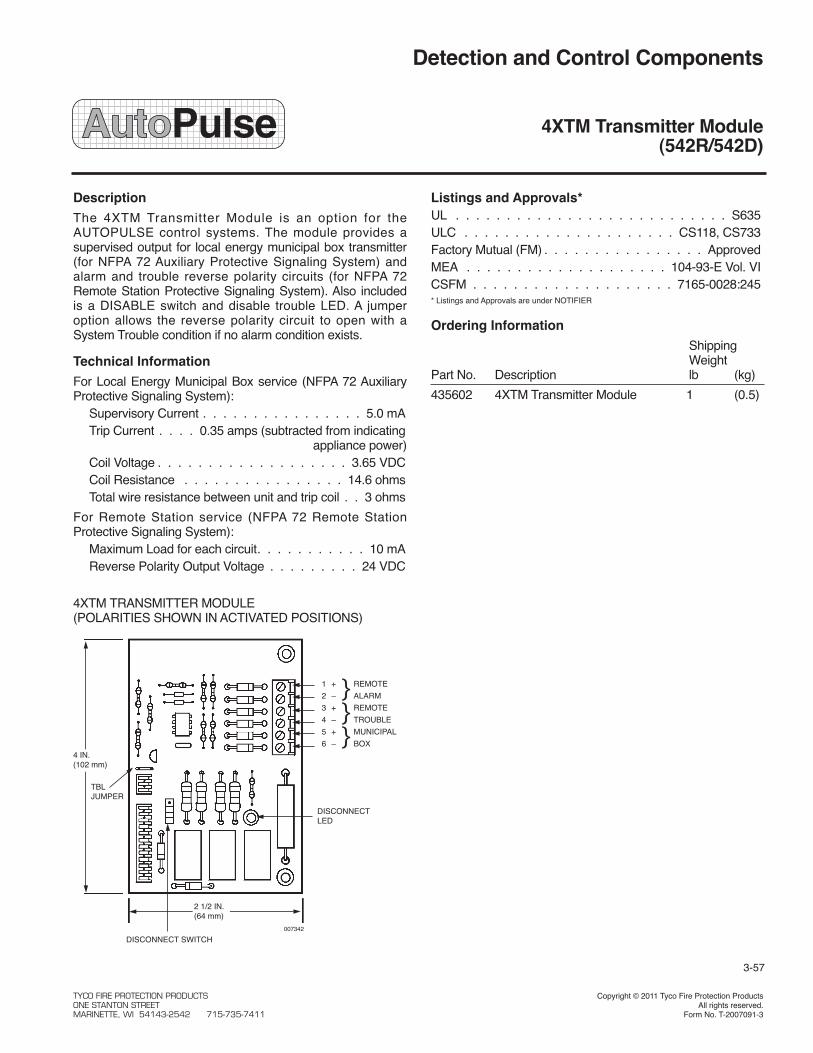
Detection and Control Components
4XTM Transmitter Module(542R/542D)
Description
The 4XTM Transmitter Module is an option for theAUTOPULSE control systems. The module provides asupervised output for local energy municipal box transmitter(for NFPA 72 Auxiliary Protective Signaling System) andalarm and trouble reverse polarity circuits (for NFPA 72Remote Station Protective Signaling System). Also includedis a DISABLE switch and disable trouble LED. A jumperoption allows the reverse polarity circuit to open with aSystem Trouble condition if no alarm condition exists.
Technical Information
For Local Energy Municipal Box service (NFPA 72 AuxiliaryProtective Signaling System):
Supervisory Current . . . . . . . . . . . . . . . . 5.0 mATrip Current . . . . 0.35 amps (subtracted from indicating
appliance power)Coil Voltage . . . . . . . . . . . . . . . . . . . 3.65 VDCCoil Resistance . . . . . . . . . . . . . . . . 14.6 ohmsTotal wire resistance between unit and trip coil . . 3 ohms
For Remote Station service (NFPA 72 Remote StationProtective Signaling System):
Maximum Load for each circuit. . . . . . . . . . . 10 mAReverse Polarity Output Voltage . . . . . . . . . 24 VDC
Listings and Approvals*UL . . . . . . . . . . . . . . . . . . . . . . . . . . . S635ULC . . . . . . . . . . . . . . . . . . . . . CS118, CS733Factory Mutual (FM) . . . . . . . . . . . . . . . . ApprovedMEA . . . . . . . . . . . . . . . . . . . . 104-93-E Vol. VICSFM . . . . . . . . . . . . . . . . . . . . 7165-0028:245* Listings and Approvals are under NOTIFIER
Ordering Information
ShippingWeight
Part No. Description lb (kg)
435602 4XTM Transmitter Module 1 (0.5)
3-57
DISCONNECT SWITCH
DISCONNECTLED
1 + REMOTE
2 – } ALARM
3 + REMOTE
4 – } TROUBLE
5 + MUNICIPAL
6 – } BOX
TBLJUMPER
4XTM TRANSMITTER MODULE(POLARITIES SHOWN IN ACTIVATED POSITIONS)
4 IN.(102 mm)
2 1/2 IN.(64 mm)
007342
TYCO FIRE PROTECTION PRODUCTS Copyright © 2011 Tyco Fire Protection ProductsONE STANTON STREET All rights reserved.MARINETTE, WI 54143-2542 715-735-7411 Form No. T-2007091-3


Detection and Control Components
3-58
(Page Left Intentionally Blank)
TYCO FIRE PROTECTION PRODUCTSONE STANTON STREET Copyright © 2011 Tyco Fire Protection ProductsMARINETTE, WI 54143-2542 715-735-7411 All rights reserved.


Detection and Control Components
3-59
(Page Left Intentionally Blank)
TYCO FIRE PROTECTION PRODUCTSONE STANTON STREET Copyright © 2011 Tyco Fire Protection ProductsMARINETTE, WI 54143-2542 715-735-7411 All rights reserved.


Features
LIFEalarm detection combines photoelectric detectionwith heat detection to provide a multi-mode detectorwith four detection mechanisms:*
• Stable and reliable photoelectric smoke detection withbuilt-in LIFEalarm sensitivity drift compensation
• Resettable, thermistor-based fixed temperature detection
• Resettable, thermistor-based rate-of-rise temperaturedetection
• A built-in analysis of photoelectric and thermal activitytrending that provides fire detection with higher accuracythan either detection means used separately
Functional chamber enclosure:
• Louvered design enhances smoke capture by directingflow to chamber
• Entrance areas are minimally visible when ceilingmounted
Multi-function LED indicator:
• Indicates normal and alarm conditions
• Provides status during magnetic functional test
Magnetically operated functional test:
• Initiates alarm and verifies performance
• Identifies general sensitivity status using detector LEDpulses (normal, more sensitive, or less sensitive)
• With detectors categorized as normal or needing cleaningor other service, maintenance priorities can be more easilydetermined
Available base options:
• Bases for 2-wire operation
• Auxiliary alarm relay output
• Remote alarm indicating LED output
Optional remote LED alarm indicator
Listings and Approvals
• UL Listed: S6648
• ULC Listed: S6648
• FM Approved: 3015976
• MEA (NYC): Approved
• CSFM: Approved
* LIFEalarm detectors are protected by one or more of the following U.S. Patents:5,155,468; 5,173,683; 5,400,014; 5,543,777; 5,710,541; 5,818,326; 6,195,011;D383,407; D388,352; D392,573.
006622
Detector (Part No. 430560) Mounted in Base
Description
LIFEalarm photoelectric smoke detectors combine photo-electric smoke detection technology and quick responsethermistor-based heat detection technology into a sophisti-cated, intelligent detector that analyzes each of these activi-ties and their combination to determine whether alarmconditions are present.
An onboard microprocessor provides four independentdetection modes: photoelectric detection with sensitivity driftcompensation, fixed temperature heat detection, rate-of-risetemperature heat detection, and photoelectric/heat trendinganalysis and alarm detection. If any of these alarm condi-tions are experienced, an alarm is initiated.
Detection and Control Components
LIFEalarm® Photoelectric Smoke Detectorswith Smoke/Heat Detection (Z-10)
Voltage 15 to 32 VDC, fromControl Panel IDC
Standby Current 100 µA @ 24 VDC
Alarm Current, Up to 86 mA maximum, exact current is2-Wire Operation determined by alarm current limiting of
connected IDC (initiating current device)
Auxiliary Relay Ratings Refer to page 3 under Product Selection
Rate-of-Rise ≤ 20° F/min (11° C/min), only effectiveTemperature Alarm* at temperatures above 90° F (32° C)
Fixed Temperature Alarm 135° F (57° C)
UL Listed Temp. Range* 32° F to 100° F (0° C to 38° C)
Operating Temp. Range 15° F to 100° F (-9° C to 38° C)
Smoke Obscuration 2.8%/ft Nominal, per UL268Sensitivity
UL Listed Temp. Range 32° to 100° F (0° to 38° C)
Operating Temp. Range 15° to 122° F (–9° to + 50° C)
Air Velocity Range 0-2000 ft/min (0-610 m/min)
Humidity Range 10% to 95% RH from 32° to 122° F(0° to 50° C)
Color Frost White
Dimensions 4 7/8 in. Dia. x 2 in. H, mounted in base(124 mm x 51 mm)
Specifications
* Always locate this and all rate-of-rise heat detection devices away fromextremes of temperature fluctuation.
3-60
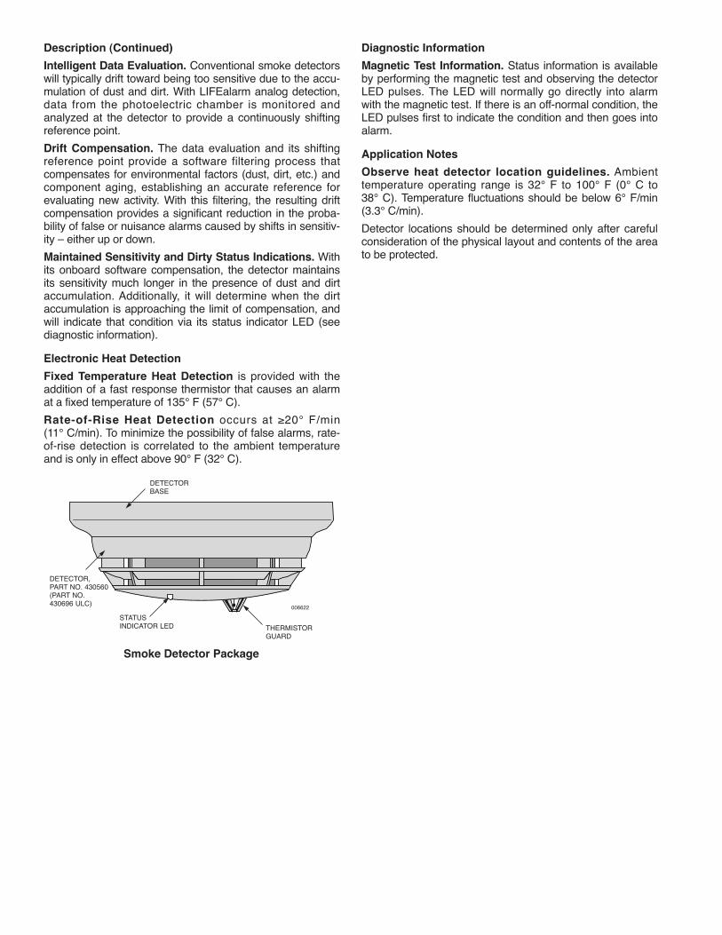
Description (Continued)
Intelligent Data Evaluation. Conventional smoke detectorswill typically drift toward being too sensitive due to the accu-mulation of dust and dirt. With LIFEalarm analog detection,data from the photoelectric chamber is monitored andanalyzed at the detector to provide a continuously shiftingreference point.
Drift Compensation. The data evaluation and its shiftingreference point provide a software filtering process thatcompensates for environmental factors (dust, dirt, etc.) andcomponent aging, establishing an accurate reference forevaluating new activity. With this filtering, the resulting driftcompensation provides a significant reduction in the proba-bility of false or nuisance alarms caused by shifts in sensitiv-ity – either up or down.
Maintained Sensitivity and Dirty Status Indications. Withits onboard software compensation, the detector maintainsits sensitivity much longer in the presence of dust and dirtaccumulation. Additionally, it will determine when the dirtaccumulation is approaching the limit of compensation, andwill indicate that condition via its status indicator LED (seediagnostic information).
Electronic Heat Detection
Fixed Temperature Heat Detection is provided with theaddition of a fast response thermistor that causes an alarmat a fixed temperature of 135° F (57° C).
Rate-of-Rise Heat Detection occurs at ≥20° F/min(11° C/min). To minimize the possibility of false alarms, rate-of-rise detection is correlated to the ambient temperatureand is only in effect above 90° F (32° C).
Diagnostic Information
Magnetic Test Information. Status information is availableby performing the magnetic test and observing the detectorLED pulses. The LED will normally go directly into alarmwith the magnetic test. If there is an off-normal condition, theLED pulses first to indicate the condition and then goes intoalarm.
Application Notes
Observe heat detector location guidelines. Ambienttemperature operating range is 32° F to 100° F (0° C to38° C). Temperature fluctuations should be below 6° F/min(3.3° C/min).
Detector locations should be determined only after carefulconsideration of the physical layout and contents of the areato be protected.
006622
THERMISTORGUARD
STATUSINDICATOR LED
DETECTORBASE
DETECTOR,PART NO. 430560(PART NO.430696 ULC)
Smoke Detector Package

ALARM
DETECTOR (PART NO. 430560) MOUNTED ON BASE
REMOTE RED LED INDICATOR(PART NO. 430572)(NOT TO SCALE)
4 7/8 IN. (124 mm)
STATUS INDICATOR LED
2 IN.(51 mm)
BASE HEIGHT11/16 IN. (17 mm)
006567
006623
Product Selection
Smoke Detector
Part No. Description Compatibility
430560 LIFEalarm photoelectric detector Compatible with detector bases: Part Nos. 430567 and 430569with photoelectric/thermal detection
Detector Bases
Part No. Description Details
430567 2-Wire Base with connections for Remote • IDC and LED connections are screw terminals forAlarm LED Indicator in/out wiring, #18 to #14 AWG
430569 2-Wire Base with Auxiliary Alarm Relay Relay Ratings, Dual Form "C," For Suppressed Loads:and connections for Remote LED Indicator • Power limited, 1 A @ 28 VDC
• Non-power limited, 1/2 A @ 120 VACNote: Must be connected as the only Wiring Connections (In/Out where required):
device on the IDC to ensure • Relay contacts and IDC (-), color coded #18 AWG leadsrelay operation. • IDC (+) and LED wiring, screw terminals for #18 to #14 AWG
Detector Accessories
Part No. Description Details
430572 Remote LED Indicator • Mounted on single gang stainless steel plate
Dimensions and Reference Information

Mounting Information
006624
SMOKE DETECTOR
PART NO. 430569 INCLUDES ARELAY MODULE THATMOUNTS IN BASE ELECTRICALBOX
1 1/2 IN. (38 mm)MINIMUM BOX DEPTH FLUSH MOUNT REFERENCE, MOUNT EVEN
WITH FINAL SURFACE, OR WITH UP TO1/4 IN. (6 mm) MAXIMUM RECESS
4 IN. SQUARE (102 mm)SQUARE BOX
4 IN. SQUARE(102 mm)OCTAGONAL BOX
SURFACE MOUNT REFERENCE
SMOKE DETECTOR BASES
ELECTRICAL BOX REQUIREMENTS:WITHOUT RELAY (BASES, PART NO. 430567):4 IN. (102 mm) OCTAGONAL OR 4 IN. (102 mm) SQUARE, 1 1/2 IN. (38 mm) DEEPSINGLE GANG, 2 IN. (51 mm) DEEPWITH RELAY (BASES, PART NO. 430569):4 IN. (102 mm) OCTAGONAL, 1 1/2 IN. (38 mm) DEEP, WITH 1 1/2 IN. (38 mm) EXTENSION RING4 IN. (102 mm) SQUARE, 1 1/2 IN. (38 mm) DEEP, WITH 1 1/2 IN. (38 mm) EXTENSION RING
LED Indication Status
Flashes every 4 seconds Circuit is Normal, power is applied
Steady On Detector is in Alarm
LED Response to Magnetic Test *
LED Indication Alarm Response Detector Status Action Required
LED turns ON Alarm is initiated Normal, sensitivity is within Nonecompensation range
Flashes quickly, 6 times in Alarm is initiated More sensitive, out of normal Cleaning or other3 seconds, then turns ON compensation range service is required
Flashes slowly, Alarm is initiated Less sensitive, out of normal4 times in 8 seconds, compensation rangethen turns ON Alarm is NOT initiated Detector is malfunctioning Service is required
Visible LED Status Indications
* Testing requires placing a magnet at the designated location on the detector cover for 4 seconds.
TYCO FIRE PROTECTION PRODUCTS Copyright © 2011 Tyco Fire Protection ProductsONE STANTON STREET All rights reserved.MARINETTE, WI 54143-2542 715-735-7411 Form No. T-2007152-3
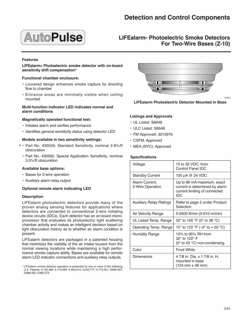
Features
LIFEalarm® Photoelectric smoke detector with on-boardsensitivity drift compensation*
Functional chamber enclosure:
• Louvered design enhances smoke capture by directingflow to chamber
• Entrance areas are minimally visible when ceilingmounted
Multi-function indicator LED indicates normal andalarm conditions
Magnetically operated functional test:
• Initiates alarm and verifies performance
• Identifies general sensitivity status using detector LED
Models available in two sensitivity settings:
• Part No. 430559, Standard Sensitivity, nominal 2.8%/ftobscuration
• Part No. 430562, Special Application Sensitivity, nominal3.5%/ft obscuration
Available base options:
• Bases for 2-wire operation
• Auxiliary alarm relay output
Optional remote alarm indicating LED
Description
LIFEalarm photoelectric detectors provide many of theproven analog sensing features for applications wheredetectors are connected to conventional 2-wire initiatingdevice circuits (IDCs). Each detector has an on-board micro-processor that evaluates its photoelectric light scatteringchamber activity and makes an intelligent decision based onlight obscuration history as to whether an alarm condition ispresent.
LIFEalarm detectors are packaged in a patented housingthat minimizes the visibility of the air intake louvers from thenormal viewing locations while maintaining a high perfor-mance smoke capture ability. Bases are available for remotealarm LED indicator connections and auxiliary relay outputs.
* LIFEalarm smoke detector operation is protected by one or more of the followingU.S. Patents: 5,155,468; 5,173,683; 5,400,014; 5,543,777; 5,710,541; D383,407;D388,352; D392,573.
006564
LIFEalarm Photoelectric Detector Mounted in Base
Listings and Approvals
• UL Listed: S6648
• ULC Listed: S6648
• FM Approved: 3015976
• CSFM: Approved
• MEA (NYC): Approved
Detection and Control Components
LIFEalarm® Photoelectric Smoke DetectorsFor Two-Wire Bases (Z-10)
Voltage 15 to 32 VDC, fromControl Panel IDC
Standby Current 100 μA @ 24 VDC
Alarm Current, Up to 86 mA maximum, exact2-Wire Operation current is determined by alarm
current limiting of connectedIDC
Auxiliary Relay Ratings Refer to page 2 under ProductSelection
Air Velocity Range 0-2000 ft/min (0-610 m/min)
UL Listed Temp. Range 32° to 100 °F (0° to 38 °C)
Operating Temp. Range 15° to 122 °F (–9° to + 50 °C)
Humidity Range 10% to 95% RH from32° to 122° F(0° to 50 °C) non-condensing
Color Frost White
Dimensions 4 7/8 in. Dia. x 1 7/8 in. H,mounted in base(124 mm x 48 mm)
Specifications
3-61

Smoke Detector Features
Intelligent Data Evaluation. Conventional smoke detectorswill typically drift toward being too sensitive due to the accu-mulation of dust and dirt. With analog detection, data fromthe photoelectric chamber is monitored and analyzed at thedetector to provide a continuously shifting reference point.
Drift Compensation. The data evaluation and its shiftingreference point provide a software filtering process thatcompensates for environmental factors (dust, dirt, etc.) andcomponent aging, establishing an accurate reference forevaluating new activity. With this filtering, the resulting driftcompensation provides a significant reduction in the proba-bility of false or nuisance alarms caused by shifts in sensitiv-ity – either up or down.
Magnetic Test Information. Status information is availableby performing the magnetic test and observing the detectorLED pulses. The LED will normally go directly into alarmwith the magnetic test. If there is an off-normal condition, theLED pulses first to indicate the condition and then goes intoalarm.
Application Reference
Detector Locations. Locations should be determined onlyafter careful consideration of the physical layout andcontents of the area to be protected.
For further detailed installation information, refer toDetectors, Sensors, and Bases Application Manual (Part No.431424).
Sensitivity Selection. The standard sensitivity detector(Part No. 430559) is recommended for most applications.When a special application for a reduced sensitivity detectoris required (Part No. 430562) should be considered.
Product Selection
Smoke Detectors
Part No. Description Nominal Sensitivity Compatibility
430559LIFEalarm Photoelectric Detector 2.8%/ft (standard) Compatible with detector bases:
430562 3.5%/ftPart Nos. 430567 and 430569
Compatible Bases
Part No. Description Details
430567 2-Wire Base with connections for • IDC and LED connections are screw terminals for Remote Alarm LED Indicator in/out wiring, 18 to 14 AWG
430569 2-Wire Base with Auxiliary Alarm Relay Relay Ratings, Dual Form "C", For Suppressed Loads:& connections for Remote LED Indicator • Power limited, 1 A @ 28 VDC
Note: Must be connected as the only device • Non-power limited, 1/2 A @ 120 VACon the IDC to ensure relay operation. Wiring Connections (In/Out where required):
430570 2-Wire Base with Remote LED Indicator • Relay contacts and IDC (–), color coded 18 AWG leads• IDC (+) and LED wiring, screw terminals for
18 to 14 AWG
Detector Accessories
Part No. Description Details
430572 Remote LED Indicator • Mounted on single gang stainless steel plate

LED Indication Status
Pulses approximately every 4 seconds Normal
Steady On Alarm
LED Response to Magnetic Test *
LED Indication Followed By Status Action
LED turns ON Alarm is initiated Normal, sensitivity is within Nonecompensation range
LED pulses quickly,6 times in 3 seconds, Alarm is initiated More sensitive, out of normal Cleaning or otherthen turns ON compensation range service is required
LED pulses slowly, Alarm is initiated Less sensitive, out of normal
4 times in 8 seconds, compensation range
then turns ON Does not initiate Alarm Detector is malfunctioning Service is required
Detector Status LED Indications
Dimensions and Reference Information
* Testing requires placing a magnet at the designated location on the detector cover for 4 seconds.
ALARM
PART NO. 430559 AND PART NO. 430562 DIMENSIONS MOUNTED ON BASE
REMOTE RED LED INDICATOR (PART NO. 430572)(NOT TO SCALE)
4 7/8 IN.(124 mm)
LED STATUS INDICATOR(WITH CLEAR LENS)
BASE HEIGHT11/16 IN. (17 mm)
1 7/8 IN.(48 mm)
006567
006565

Mounting Information
006566
FLUSH MOUNT REFERENCE, MOUNT EVEN WITH FINALSURFACE, OR WITH UP TO 1/4 IN. (6 mm) MAXIMUM RECESS
4 IN. (102 mm)SQUARE BOX
4 IN. (102 mm)OCTAGONAL BOX
1 1/2 IN. (38 mm)MINIMUM BOX DEPTH
PART NO. 430569 INCLUDES ARELAY MODULE THAT MOUNTSIN BASE ELECTRICAL BOX
SMOKE DETECTOR BASES(PART NOS. 430567 AND 430569)
SMOKE DETECTOR (PARTNOS. 430559 AND 430562)
SURFACE MOUNT REFERENCE
ELECTRICAL BOX REQUIREMENTS:WITHOUT RELAY (BASE, PART NO. 430567):4 IN. (102 mm) OCTAGONAL OR 4 IN. (102 mm) SQUARE, 1 1/2 IN. (38 mm) DEEPSINGLE GANG, 2 IN. (51 mm) DEEPWITH RELAY (BASE, PART NO. 430569):4 IN. (102 mm) OCTAGONAL, 1 1/2 IN. (38 mm) DEEP, WITH 1 1/2 IN. (38 mm) EXTENSION RING4 IN. (102 mm) SQUARE, 1 1/2 IN. (38 mm) DEEP, WITH 1 1/2 IN. (38 mm) EXTENSION RING
TYCO FIRE PROTECTION PRODUCTS Copyright © 2011 Tyco Fire Protection ProductsONE STANTON STREET All rights reserved.MARINETTE, WI 54143-2542 715-735-7411 Form No. T-2007153-3

Features
Accurate and reliable heat detection for protection ofproperty
Available with rate-of-rise temperature detection:
• Dual thermistor rate-of-rise operation
• For use where anticipated ambient temperature changesare less than 6 °F/minute (3.33 °C/minute)
Epoxy encapsulated electronic design provides:
• Easily tested, self-restoring operation with repeatableaccuracy
• Alarm indicating LED located on detector
• Current limited alarm that is compatible with two wire initi-ating device circuits (IDCs)
Optional remote alarm indicating LED
Available base options:
• Bases for 2-wire operation
• Auxiliary relay output (refer to selection chart on for relayratings)
• Remote alarm indicating LED output
Description
Rate-of-rise detection is determined by comparing two ther-mistor responses. By combining accurate thermistors withproper physical placement, this patented rate-of-rise detec-tion design achieves a high level of performance notnormally available with mechanical detection.
Listings and Approvals
• UL Listed: S6651
• ULC Listed: S6651
• FM Approved: 3015976
• CSFM (Approved)
• MEA (NYC) (Approved)
006570
Electronic Heat Detector Mounted in Base
Hazardous levels of smoke and toxic gas can build upbefore the heat detection device initiates an alarm. Toensure the safety of personnel, the use of smokedetection is highly recommended.
Applications Reference
Heat detectors are used where property protection isdesired and where life safety protection is not required or isperformed by other equipment.
The rate-of-rise operation provides heat detection for usewhere temperature fluctuations are controlled and are lessthan 6 °F/min (3.33 °C/min). Where temperatures may fluc-tuate more quickly, use fixed temperature detection.
Refer to NFPA 72, the National Fire Alarm Code, for addi-tional guidance in applying and locating heat detectors.
Alarm Indicating LED Operation
The heat detector LED turns ON continuously when inalarm. During normal conditions the LED is OFF.
Electronic heat detector design is protected by the following U.S. Patents:5,450,066; DES.377,460.
! WARNING
Detection and Control Components
Electronic Heat DetectorsFor Two-Wire Bases (Z-10)
Voltage 15 to 32 VDC (filtered DC with30% maximum ripple)
Standby Current 80 μA typical, 100 μA maximum
Alarm Current, Up to 100 μA maximum, exact2-Wire Operation current is determined by alarm
current limiting of connectedIDC
Rate-of-Rise Operation Meets FM requirements foroperation between 15° and 25°F/min (8.33° and 13.88 °C/min)
Humidity Range 10% to 95% RH from 32° to122 °F (0° to 50 °C), notintended for outdoorapplications
Color Frost-White
Dimensions Refer to diagram on page 3
Ambient Temperature Operating Range
135° F Models 32° to 100 °F (0° to 38 °C)
200° F Models 32° to 150 °F (0° to 66 °C)
Specifications
3-62

Heat Detector Selection Chart
Fixed Temperature Rate-of-RisePart No. Operation at Operation
430565 135 °F (57 °C)Between 15° and 25° F/min
430566 200 °F (93 °C) (8.33° and 13.88° C/min)
Heat Detector Base Selection Chart
Smoke Detectors
Part No. Description Connection Details
430567 2-Wire Base, with connections IDC connections Screw terminals for in/out wiring, 18 to 14 AWGfor remote LED alarm indicator
430570 2-Wire Base with remote IDC connections Screw terminals for 18 to 14 AWG for in/out wiringLED alarm indicator of zone (+), color coded 18 AWG leads for in/out
wiring of zone (–)
LED connections Color coded 18 AWG leads
430569 2-Wire Base with auxiliary Relay Operation Type Relay Ratingsalarm relay output Power-limited 1 A @ 28 VDC Dual Form "C" contacts,
for suppressed loads
Note: Must be connected as Nonpower-limited 3 A @ 120 ACthe only device on the IDC to Output Type Wiring Connectionsensure relay operation.
IDC connections Screw terminals for 18 to 14 AWG for in/outwiring of zone (+), color coded 18 AWG leads for in/out wiring of zone (–)
Relay connections Color coded 18 AWG leads
Heat Detector Accessories
Part No. Description Details Base Compatibility
430572 Remote Red LED Mounted on single gang stainless steel plate, wiring Part No. 430570 onlyAlarm Indicator connections are 18 AWG color coded leads
430573 End-of-Line Relay Epoxy encapsulated design, 24 VDC operation, —wiring connections are 18 AWG color coded leads
Metric wire equivalents: 18 AWG = 0.82 mm2; 14 AWG = 2.08 mm2

Dimensions and Reference Information
ALARM
REMOTE RED LED INDICATOR (PART NO. 430572)(NOT TO SCALE)
4 7/8 IN.(124 mm)
LED STATUS INDICATOR
BASE HEIGHT11/16 IN. (17 mm)
2 3/8 IN.(60 mm)
006567
006571

Mounting Information
006572
FLUSH MOUNT REFERENCE, MOUNT EVENWITH FINAL SURFACE, OR WITH UP TO1/4 IN. (6 mm) MAXIMUM RECESS
1 1/2 IN. (38 mm)MINIMUM BOXDEPTH
4 IN. (102 mm)OCTAGONAL ORSQUARE BOX SURFACE MOUNT
REFERENCE
HEAT DETECTOR BASES (PARTNOS. 430569 AND 430570)
BASE (PART NO. 430569) INCLUDES A RELAYTHAT MOUNTS IN BASE ELECTRIC BOX
BASE (PART NO. 430570) INCLUDES A REMOTELED INTERFACE MODULE THAT MOUNTS IN BASEELECTRICAL BOX
HEAT DETECTOR
Base Electrical Box Requirements
430567 4 in. (102 mm) octagonal or 4 in. (102 mm)square box, 1-1/2 in. (38 mm) deep
Single gang box, 2 in. (51 mm) deep
430569 4 in. (102 mm) octagonal or 4 in. (102 mm) 430570 square box, 1-1/2 in. (38 mm) deep with
1-1/2 in. (38 mm) deep extension ring(see diagram below)
TYCO FIRE PROTECTION PRODUCTS Copyright © 2011 Tyco Fire Protection ProductsONE STANTON STREET All rights reserved.MARINETTE, WI 54143-2542 715-735-7411 Form No. T-2007159-3

Features
• Abort switches provide a manual Fire SuppressionSystem release abort request:
– Pushbutton momentary switch is mounted on a stainlesssteel single-gang plate
– A protruding collar protects the switch from accidentalcontact (collar is removable if required)
– Available flush or surface mount
– Flush mounting requires standard single-gang box
– Surface mounting includes a red mounting box
– Models are available with internal 1.2kΩ resistor forcurrent limited operation
• Maintenance switches provide a secure and visibledisconnect means for servicing Fire SuppressionSystem Releasing Appliance Circuits (RACs):
– Maintained position keyswitch is mounted on a stainlesssteel double-gang plate
– Key is removable in either normal or disabled position
– Disabled position opens connection to output circuit toinitiate a supervisory condition at the host panel
– Disconnect indicator lamp is a bright incandescent bulbwith red lens, powered from separate 24 VDC
– Available for flush or surface mount
– Flush mounting requires a standard double-gang box
– Surface mount models include a red mounting box
• UL listed to Standard 864, 9th Edition
Description
Releasing systems typically require maintenance disconnectswitches and often require abort switches. These abort andmaintenance switches are clearly labeled and combine easyoperation with rugged construction for high integrity opera-tion.
006550
Abort Switch
006549
Maintenance Switch with Disconnect Indicator Lamp
Detection and Control Components
Abort Switches and Releasing Appliance Circuit(RAC) Maintenance Switches (Z-10)
3-63
Electrical Ratings
Abort Switch; Silver contacts; 1 NO & 1 NC;One Contact block rated 2 A resistive @ 30 VDC
Maintenance Switch Circuit control: Silver contacts;with Lamp; 1 NO & 1 NC; rated 2ATwo Contact blocks resistive @ 30 VDC
Lamp control: Silver contacts;1 Form C; rated 2 A resistive@ 30 VDC
Maintenance Switch Replaceable 2 W incandescentIndicator Light bulb; 24 to 30 VDC typical;
83 mA @ 35 VDC; requires-separate 24 VDC
Wiring Connections
Abort Switch Terminal blocks for in/out wiring;18 to 14 AWG wire (0.82 mm2
to 2.08 mm2)
Abort Switch with Terminal blocks for first wireCurrent Limited Resistor connection; 18 to 14 AWG wire
(0.82 mm2 to 2.08 mm2); 18AWG wire lead for second wireconnection
Maintenance Switch 18 AWG (0.82 mm2) color codedwire leads for suppression circuit;terminal blocks for lamp wiring;18 to 14 AWG wire (0.82 mm2 to2.08 mm2)
Environmental Ratings
Temperature Range 32 °F to 120 °F (0 °C to 49 °C)
Humidity Range Up to 93% at 90 °F (32 °C)
Specifications

ABORT SWITCH WIDTH,2 3/4 IN. (70 mm)
2 3/4 IN.(70 mm)
ABORTSWITCHHEIGHT,4 1/2 IN.(114 mm)
BOX WIDTH,3 IN. (76 mm)
007712
BOXHEIGHT,
4 13/16 IN.(122 mm)
REMOVABLECOLLAR
SWITCHRECESS DEPTH5/32 IN. (4 mm)
RED BOX IS SUPPLIED WITHSURFACE MOUNT ABORTSWITCH 2080-9057 OR 2080-90682 1/4 IN. (56 mm) INTO BOX
1/2 IN.(13 mm)
SUPPLIED GASKETATTACHES TO BOX; FIELDINSTALLED FOR FLUSHMOUNT; PRE-ATTACHEDFOR SURFACE MOUNT
NOTE: FOR FLUSH MOUNTING,USE A 2 3/4 IN. DEEP (70 mm)SINGLE-GANG BOX
Abort Switch Installation Reference
MAINTENANCE SWITCH WIDTH,4 9/16 IN. (116 mm)
2 3/4 IN.(70 mm)
4 1/2 IN.(114 mm)
BOX DIMENSIONS,4 13/16 IN. (122 mm) SQUARE
007713
RED BOX IS SUPPLIEDWITH SURFACE MOUNTMAINTENANCE SWITCH2 1/4 IN. (56 mm) INTO BOX
SUPPLIED GASKET ATTACHESTO BOX; FIELD INSTALLED FORFLUSH MOUNT; PRE-ATTACHEDFOR SURFACE MOUNT
NOTE: FOR FLUSH MOUNTING,USE A 2 3/4 IN. DEEP (70 mm)SINGLE-GANG BOX
Maintenance Switch Installation Reference
Listings and Approvals
UL Listed . . . . . . . . . . . . . . . . . . . . S8332
ULC Listed . . . . . . . . . . . . . . . . . . . S8332
CSFM . . . . . . . . . . . . . . . . . . . . Approved
MEA (NYC) . . . . . . . . . . . . . . . . . Approved
Ordering Information ShippingWeight
Part No. Description lb (kg)
433936 Flush Mount Maintenance Switch 2 (0.9)433937 Surface Mount Maintenance Switch 2 (0.9)433940 Flush Mount Abort Switch 1 (0.5)
TYCO FIRE PROTECTION PRODUCTS Copyright © 2011 Tyco Fire Protection ProductsONE STANTON STREET All rights reserved.MARINETTE, WI 54143-2542 715-735-7411 Form No. T-2007161-3

Features
• Isolated Loop Circuit Protector (ILCP) for up to 5 A ofDC or audio current:
– Low impedance design minimizes voltage drop
– For internal or external applications (refer to page 2 forexternal wiring requirements)
– Refer to specific panel field wiring diagrams for addi-tional application information
• Operation is compatible with**:
– DC notification appliance circuits (NACs)
– Speaker circuit NACs (25 VRMS)
• Multiple stages of protection for DC and audiocircuits:
– Line-to-Line Protection
– Line-to-Earth Protection
• Rugged epoxy encapsulated package
Description
Electrical transients caused by lightning or by disturbanceson high voltage power lines are conditions that require lowvoltage wiring circuits to be adequately protected. Thisprotection is most effective when placed at the locationwhere such circuits leave or enter the building.
The Isolated Loop Circuit Protector (ILCP) (Part No.430685) is designed to protect Fire Alarm circuits from thoseelectrical transients induced on wire runs that are routedexternal to the building. Because of its small package size, itcan be easily mounted at the location that achievesmaximum protection.
** Performance of this device has been quantified for use with other circuit typesfor specific applications where its low resistance is desired.
Listings and Approvals
UL Listed . . . . . . . . . . . . . . . . . . . . . E197916
006581
Isolated Loop Circuit Protector (Part No. 430685)
L
I
N
E
E
Q
U
I
P
Detection and Control Components
Isolated Loop Circuit Protector,Part No. 430685 (Z-10)
Line-to-Line Rating38 VDC, 28 VAC RMS
Line-to-Ground Rating
Shield-to-Ground Rating 48 VDC, 33 VAC RMS
Continuous Current Rating 5 A
Series Resistance 0.1 Ω/line
Series Inductance 68 μH/line
Shunt Capacitance 0.017 μF
Response Time <1 Nanosecond (10-9)line-to-line and line-to-earth
Maximum CurrentLine-to-Line and 2000 A (8 x 20 μsec pulse)Line-to-Earth
Maximum Current 5000 A (10 x 50 μsec)Shield-to-Earth
Mechanical Specifications
Dimensions 3 3/8 in. W x 2 in. D x 1 in. H(86 mm x 50 mm x 25 mm)
Package Epoxy encapsulated, beige
Electrical box requirement 4 in. (102 mm) square box,2 1/8 in. (54 mm)minimum depth
Wire Leads Color coded, #18 AWG,8 in. long (203 mm)
Operating Specifications
3-64

External Wiring Requirements
Fire alarm system wiring that is run external to the buildingand is protected by the use of ILCPs shall be installed inaccordance with the individual system component’s installa-tion instructions including properly grounded, twisted andshielded pairs, and observance of the following precautions.
Location. To ensure optimized protection, the ILCPs shallbe located as close as possible to the point at which thecircuits leave or enter the buildings and installed in dedi-cated metallic electrical boxes.
Wiring Distance. Wiring is limited to one contiguous prop-erty. The total maximum wire length is determined by theindividual application’s allowable limit as specified withILCPs, but must not exceed 3270 ft (996.7 m).
Underground Wiring. Wiring must be in a wiring trough thatis separate from commercial power distribution wiring.
Overhead Wiring
1. Wiring must be run on poles separate from thosesupporting any commercial power distribution wiring.
2. Wiring shall be run in parallel with the commercial powerdistribution wiring and be separated by a minimumdistance of either 100 ft (30 m) or the maximum spanbetween any two adjacent poles of either the system’scircuit or the commercial power distribution circuit.
The grounding conductor shall be #12 AWG with amaximum length of 28 ft (8.5 m), run in as straight a line aspossible and connected to the building grounding electrodesystem (unified earth ground) per Article 800-40 of NFPA 70,the National Electrical Code.
006584
INDOORS OUTDOORS INDOORS
LINE A TO THE NEXT
LINE B
CONNECTED
PROTECTOR
LINE A
LINE B
CABLESHIELD(IF USED)
PROTECTEDEQUIPMENT
Typical Connections
CABLESHIELD(IF USED)
GROUNDSCREW
GROUNDSCREW
# 12 AWG (MIN.)
28 FT (8.5 m) MAX. 4 IN. (102 mm) SQUARE BOX, 2 1/8 IN.(54 mm) DEEP OR EQUIVALENT(BY OTHERS)
# 12 AWG (MIN.)
INTERNAL CIRCUIT
ILCP (PART NO. 430685)
TYCO FIRE PROTECTION PRODUCTS Copyright © 2011 Tyco Fire Protection ProductsONE STANTON STREET All rights reserved.MARINETTE, WI 54143-2542 715-735-7411 Form No. T-2007156-3

Detection and Control Components
ANSUL AUTOMAN II-C Releasing Device
Applications
The ANSUL AUTOMAN II-C is an automatic, electric pneu-matic releasing device for actuating a fire suppression sys-tem upon receipt of an electrical input signal. It may be auto-matically actuated via a detection/control system and/or man-ually through use of an integral manual strike button; orthrough use of a remote electric or remote mechanical pullstation.
Description
The device is made up of an enclosure, releasing device andauxiliary switch. The NEMA Type I all-steel enclosure hasfour holes for surface mounting and a hinged cover with keylock. The cover contains a window for visual verification thatthe releasing device is armed. A standard pattern of wiringknockouts is provided, and connections are made to heavyduty screw terminals – no soldering required.
The releasing device has a stored pressure cartridge (orderseparately) and provides pneumatic actuation for the releasemechanisms on agent container tanks. Pressure is releasedfrom the cartridge by piercing the cartridge seal with amechanical puncture pin. The pin release can be accom-plished manually through a STRIKE button on the front coveror automatically through the solenoid. Optional electric ormechanical manual pull stations provide additional actuationcapability, if desired. An auxiliary switch may be used to pro-vide shutdown of equipment or provide feedback of actuationto the detection/control system.
Technical Information
Temperature Range:. . . +32 °F to +120 °F (0 °C to +49 °C)
Solenoid Voltage:. . . . . . . . . . . . . . 24 VDC Nominal
Solenoid Operating Current: . . . . . . . 750 mA @ 24 VDC
Solenoid on Time: . . . . . . . . . . . . . . . . . . . 50 mS
Coil Resistance: . . . . . . . . . . . . . . . . . . . . . 26Ω
Auxiliary Switch Contact Ratings: . . . . . 20A, 125/250VAC2 HP, 250VAC1 HP, 125VAC
Weight: . . . . . . . . . . . . . . . . . . . . 26 lb (11.8 kg)
Overall Dimensions:
Height. . . . . . . . . . . . . . . . . . 24.5 in. (662 mm)
Width . . . . . . . . . . . . . . . . . . 12.5 in. (311 mm)
Depth . . . . . . . . . . . . . . . . . . 4.25 in. (108 mm)
004653
The release contains a second integral switch which shuts offthe solenoid after operation, approximately 50 mS.Supervision can be accomplished by passing a limited cur-rent of 50 mA or less through the solenoid circuit.
The number of devices that can be operated from the pneu-matic output of one ANSUL AUTOMAN II-C is determined bythe minimum anticipated temperature, the amount of pipingrequired, and the nature of the devices being actuated. Ifadditional actuation capability should ever be required as anoption, remote pressure booster type actuators can readily fillthe need.
3-65
KNOCKOUTS ON4 SIDES OF BOX
1 IN.(25 mm)
5/16 IN. DIAMETERHOLES
22 1/8 IN.(562 mm)
1 1/8 IN.(29 mm)
4 1/4 IN.(108 mm)
9 7/8 IN.(251 mm)
000466
000465
MOUNTING DIMENSIONS

Approvals
The ANSUL AUTOMAN II-C releasing device is UnderwritersLaboratories listed for use with piped, fixed nozzle fire sup-pression systems (R5998). It complies with the requirementsof all current applicable NFPA standards covering fire extin-guishing agent systems.
Ordering InformationShippingWeight
Part No. Description lb (kg)
17728 ANSUL AUTOMAN II-C Assembly 26 (11.8)
35619 Weatherproof 28 (12.7)ANSUL AUTOMAN II-C Assembly
17966 Lock with 2 Keys 0.25 (0.1)
70480 Key 0.1 (0.05)
TYCO FIRE PROTECTION PRODUCTS Copyright © 2011 Tyco Fire Protection ProductsONE STANTON STREET All rights reserved.MARINETTE, WI 54143-2542 715-735-7411 Form No. T-2007149-3

Detection and Control Components
ANSUL AUTOMAN II-CExplosion-Proof Releasing Device
Applications
The explosion-proof ANSUL AUTOMAN II-C is an automatic,electric pneumatic releasing device which, upon receipt of anelectrical input signal, actuates the fire suppression systemwhich is installed in a hazardous location.
It may be automatically actuated via a detection/control sys-tem and/or manually through use of an integral manual strikebutton; or through use of a remote electric or, mechanicalremote pull station.
Description
The device is made up of an enclosure, and releasingdevice. The NEMA Type I all steel enclosure has four holesfor surface mounting and a hinged cover with key lock. Thecover contains a window for visual verification that the releas-ing device is armed. Wiring knockouts are provided, and con-nections are made to the solenoid through two 18 AWGleads exiting the conduit fitting on the explosion-proof sole-noid.
The releasing device uses a stored pressure nitrogen car-tridge and provides pneumatic actuation for the agent con-tainer tank valve. Pressure is released by piercing the car-tridge seal with a mechanical puncture pin. The pin releasecan be accomplished manually through a STRIKE button onthe front cover or automatically through the solenoid.Optional electric or mechanical manual pull stations provideadditional actuation capability, if desired.
To provide shutdown of equipment or provide feedback ofactuation to the detection/control equipment, an explosion-proof pressure switch (not provided) can be added to thesystem.
The explosion-proof releasing device is suitable for use in thefollowing areas: Class I, Groups C and D HazardousLocations.
Technical Information
Temperature Range: . . . . . 32 °F to 130 °F (0 °C to 54 °C)Part Number: 31492 32525 32526_____ _____ _____Operating Voltage:. . . . 24 VDC 120 VAC 240 VACOperating Current:. . . . 500 mA 100 mA 50 mACoil Resistance: . . . . . 52 ohms 100 ohms 200 ohms
Solenoid Rating: . . . . . Explosion-proof, Continuous Duty
Weight:. . . . . . . . . . . . . . . . . . . . . 26 lb (11.8 kg)
Overall Dimensions:
Height . . . . . . . . . . . . . . . . . . 24.5 in. (662 mm)
Width . . . . . . . . . . . . . . . . . . 12.5 in. (311 mm)
Depth . . . . . . . . . . . . . . . . . . 4.25 in. (108 mm)
004653
The explosion-proof ANSUL AUTOMAN II-C CANNOT beused with a CO2 Cartridge. Although other cartridges willfit, they MUST NEVER be used in this unit.
Use only the LT-30-R Nitrogen cartridge (Part No. 5373).
The solenoid employed is rated for continuous duty. Should itbe desirable to interrupt power to the solenoid after systemactuation, an explosion-proof pressure switch can be utilized.
The number of devices that can be operated from the pneu-matic output of one ANSUL AUTOMAN II-C is determined bythe minimum anticipated temperature, the amount of pipingrequired, and the required pressure to operate the devicesbeing actuated. If additional actuation capability should everbe required, as an option, remote pressure booster typeactuators can readily fill the need.
CAUTION
3-66
KNOCKOUTS ON4 SIDES OF BOX
1 IN.(25 mm)
5/16 IN. DIAMETERHOLES
22 1/8 IN.(562 mm)
1 1/8 IN.(29 mm)
4 1/4 IN.(108 mm)
9 7/8 IN.(251 mm)
000466
000465
MOUNTING DIMENSIONS

Listings and ApprovalsThe ANSUL AUTOMAN II-C explosion-proof releasing deviceis Underwriters Laboratories listed (E62842) for use in Class1, Groups C and D Hazardous Locations with piped, fixednozzle fire suppression systems.
It complies with the requirements of all current applicableNFPA Standards covering fire extinguishing agent systems.
Ordering InformationShipping Weight
Part No. Description lb (kg)_______ _________ ___________
31492 ANSUL AUTOMAN II-C 26 (11.8)Explosion-Proof ReleasingDevice, 24 VDC
32525 ANSUL AUTOMAN II-C 26 (11.8)Explosion-Proof ReleasingDevice, 120 VAC
32526 ANSUL AUTOMAN II-C 26 (11.8)Explosion-Proof ReleasingDevice, 240 VAC
TYCO FIRE PROTECTION PRODUCTS Copyright © 2011 Tyco Fire Protection ProductsONE STANTON STREET All rights reserved.MARINETTE, WI 54143-2542 715-735-7411 Form No. T-2007150-3