Detecting and imaging hard-to-find abandoned wells and ... · PDF filewhen no government...
4
In 1859, Colonel E. L. Drake drilled a successful oil well in Oil Creek, Pennsylvania, USA, and ignited a frenzied era of oil and gas exploration in the country. Several thousand oil and gas wells were drilled in the next few decades, a time when no government regulations or guidelines were in place to document drilling activity and there were no laws requir- ing exploration and/or drilling companies to remediate and/or plug abandoned wells. As a result, there are thou- sands of poorly documented or undocumented oil and gas wells scattered across the country, creating serious public safety and environmental issues. This was highlighted on 15 October 1987 when an 18- month-old girl fell 22 ft down an abandoned well in Midland, Texas. It took rescuers two-and-a-half days to dig a tunnel and safely rescue her. Although this event received consid- erable attention in major news media, the safety issues remain. Other small children and animals have fallen into abandoned wells in other parts of the country and there are instances where people unknowingly built homes on top of abandoned wells—a hazardous situation because gas build- up can occur or oil can seep through foundations via cracks and plumbing. Open holes act as conduits for natural gas to migrate from deeper strata or from coal seams. Abandoned and unplugged open wells also are a serious public safety issue because they can funnel untreated surface runoff into shal- low aquifers used as a source of drinking water. Unfortunately, and somewhat surprisingly, finding aban- doned oil/gas rigs can frequently be difficult. For example, as shown in Figure 1, they are often barely visible on forested hillsides in the Appalachian Basin where many have been abandoned for decades. Plugging such wells is also often complicated by surface topography which makes it difficult to access the area (Figure 2). To compound the problem of detecting these abandoned wells, steel casings from many were removed and recycled during World War II. These wells were rarely plugged and, consequently, detecting them became more difficult and would require the development of portable, advanced geophysical tools. This article is based on field trials we conducted, with support from several coal companies, over two years to determine the best technology to directly and indirectly detect/image abandoned wells. Our conclusion is that the digital multifrequency electromagnetic (EM) method is the best technique for this purpose. However, as indicated in the following case histories, each site also had its own unique set of problems and challenges and, thus, required con- ducting various tests to determine the proper source fre- quencies that would make any anomalies detectable. A twin well problem. The thickly forested study area is near the top of a mountain ridge in West Virginia. Based on vin- tage maps and an old timer’s recollection, two abandoned wells were assumed. It was common practice at the turn of the 20 th century for drillers who encountered problems with a hole to just simply swing the rig 180° and drill a second hole nearby. Coal company engineers found the first well and, using the length of typical drill rigs of that vintage era, looked for the second well within a 30-ft diameter. In Figure 3, a digital EM image of the study area, the first abandoned well is near coordinates (65,-25). The sur- vey was expanded to cover a larger area which measured 40 ǂ 80 ft and a similar signature was detected at (10,-25), 55 ft away from the first abandoned well instead of the expected 30 ft. Apparently, the drillers not only swung the rig around, but also moved an extra 25 ft for some unknown operational reason. A similar but smaller signature near coordinates (15,-30) was interpreted to be an artifact of the survey. A straight Detecting and imaging hard-to-find abandoned wells and pipelines LAWRENCE M. GOCHIOCO, LM Gochioco & Associates, Houston, USA FRED RUEV JR., LM Gochioco & Associates, Pittsburgh, USA 358 THE LEADING EDGE MARCH 2006 Figure 1. An abandoned oil/gas rig in a forest in the Appalachian Basin. Figure 2. A site where access/data acquisition is difficult. Figure 3. A twin-well problem. The first abandoned well was found near (65, -25), but finding the second (10, -25) required a digital EM survey.
Transcript of Detecting and imaging hard-to-find abandoned wells and ... · PDF filewhen no government...

In 1859, Colonel E. L. Drake drilled a successful oil well inOil Creek, Pennsylvania, USA, and ignited a frenzied era ofoil and gas exploration in the country. Several thousand oiland gas wells were drilled in the next few decades, a timewhen no government regulations or guidelines were in placeto document drilling activity and there were no laws requir-ing exploration and/or drilling companies to remediateand/or plug abandoned wells. As a result, there are thou-sands of poorly documented or undocumented oil and gaswells scattered across the country, creating serious publicsafety and environmental issues.
This was highlighted on 15 October 1987 when an 18-month-old girl fell 22 ft down an abandoned well in Midland,Texas. It took rescuers two-and-a-half days to dig a tunneland safely rescue her. Although this event received consid-erable attention in major news media, the safety issuesremain. Other small children and animals have fallen intoabandoned wells in other parts of the country and there areinstances where people unknowingly built homes on top ofabandoned wells—a hazardous situation because gas build-up can occur or oil can seep through foundations via cracksand plumbing.
Open holes act as conduits for natural gas to migratefrom deeper strata or from coal seams. Abandoned andunplugged open wells also are a serious public safety issuebecause they can funnel untreated surface runoff into shal-low aquifers used as a source of drinking water.
Unfortunately, and somewhat surprisingly, finding aban-doned oil/gas rigs can frequently be difficult. For example,as shown in Figure 1, they are often barely visible on forestedhillsides in the Appalachian Basin where many have beenabandoned for decades. Plugging such wells is also oftencomplicated by surface topography which makes it difficultto access the area (Figure 2). To compound the problem ofdetecting these abandoned wells, steel casings from manywere removed and recycled during World War II. Thesewells were rarely plugged and, consequently, detecting thembecame more difficult and would require the developmentof portable, advanced geophysical tools.
This article is based on field trials we conducted, withsupport from several coal companies, over two years todetermine the best technology to directly and indirectlydetect/image abandoned wells. Our conclusion is that thedigital multifrequency electromagnetic (EM) method is thebest technique for this purpose. However, as indicated inthe following case histories, each site also had its own uniqueset of problems and challenges and, thus, required con-ducting various tests to determine the proper source fre-quencies that would make any anomalies detectable.
A twin well problem. The thickly forested study area is nearthe top of a mountain ridge in West Virginia. Based on vin-tage maps and an old timer’s recollection, two abandonedwells were assumed. It was common practice at the turn ofthe 20th century for drillers who encountered problems witha hole to just simply swing the rig 180° and drill a secondhole nearby. Coal company engineers found the first welland, using the length of typical drill rigs of that vintage era,looked for the second well within a 30-ft diameter.
In Figure 3, a digital EM image of the study area, the
first abandoned well is near coordinates (65,-25). The sur-vey was expanded to cover a larger area which measured40 � 80 ft and a similar signature was detected at (10,-25),55 ft away from the first abandoned well instead of theexpected 30 ft. Apparently, the drillers not only swung therig around, but also moved an extra 25 ft for some unknownoperational reason.
A similar but smaller signature near coordinates (15,-30)was interpreted to be an artifact of the survey. A straight
Detecting and imaging hard-to-find abandoned wells and pipelinesLAWRENCE M. GOCHIOCO, LM Gochioco & Associates, Houston, USAFRED RUEV JR., LM Gochioco & Associates, Pittsburgh, USA
358 THE LEADING EDGE MARCH 2006
Figure 1. An abandoned oil/gas rig in a forest in the Appalachian Basin.
Figure 2. A site where access/data acquisition is difficult.
Figure 3. A twin-well problem. The first abandoned well was found near(65, -25), but finding the second (10, -25) required a digital EM survey.
acquisition line could not be maintained in the heavilywooded area (see Figure 2), and the surveyor came close tothe second well on the return pass. Engineers did later con-firm the location of the second well.
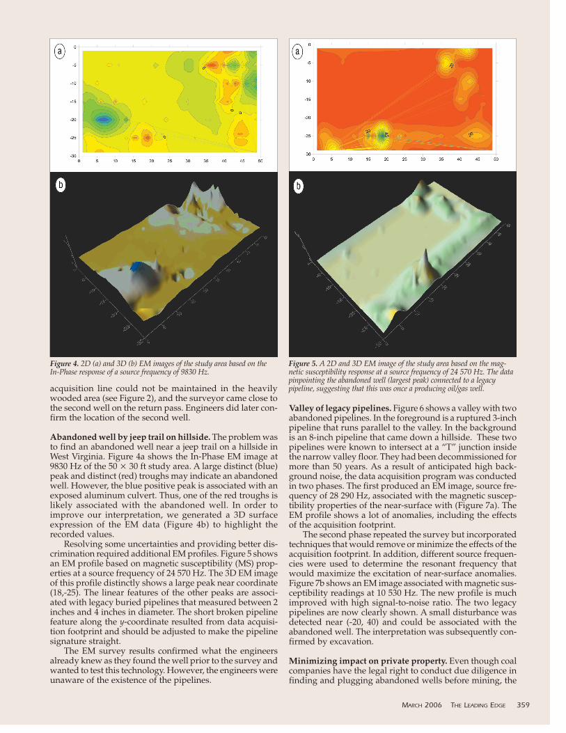
Abandoned well by jeep trail on hillside. The problem wasto find an abandoned well near a jeep trail on a hillside inWest Virginia. Figure 4a shows the In-Phase EM image at9830 Hz of the 50 � 30 ft study area. A large distinct (blue)peak and distinct (red) troughs may indicate an abandonedwell. However, the blue positive peak is associated with anexposed aluminum culvert. Thus, one of the red troughs islikely associated with the abandoned well. In order toimprove our interpretation, we generated a 3D surfaceexpression of the EM data (Figure 4b) to highlight therecorded values.
Resolving some uncertainties and providing better dis-crimination required additional EM profiles. Figure 5 showsan EM profile based on magnetic susceptibility (MS) prop-erties at a source frequency of 24 570 Hz. The 3D EM imageof this profile distinctly shows a large peak near coordinate(18,-25). The linear features of the other peaks are associ-ated with legacy buried pipelines that measured between 2inches and 4 inches in diameter. The short broken pipelinefeature along the y-coordinate resulted from data acquisi-tion footprint and should be adjusted to make the pipelinesignature straight.
The EM survey results confirmed what the engineersalready knew as they found the well prior to the survey andwanted to test this technology. However, the engineers wereunaware of the existence of the pipelines.
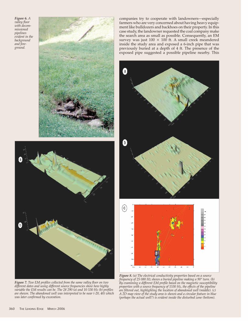
Valley of legacy pipelines. Figure 6 shows a valley with twoabandoned pipelines. In the foreground is a ruptured 3-inchpipeline that runs parallel to the valley. In the backgroundis an 8-inch pipeline that came down a hillside. These twopipelines were known to intersect at a “T” junction insidethe narrow valley floor. They had been decommissioned formore than 50 years. As a result of anticipated high back-ground noise, the data acquisition program was conductedin two phases. The first produced an EM image, source fre-quency of 28 290 Hz, associated with the magnetic suscep-tibility properties of the near-surface with (Figure 7a). TheEM profile shows a lot of anomalies, including the effectsof the acquisition footprint.
The second phase repeated the survey but incorporatedtechniques that would remove or minimize the effects of theacquisition footprint. In addition, different source frequen-cies were used to determine the resonant frequency thatwould maximize the excitation of near-surface anomalies.Figure 7b shows an EM image associated with magnetic sus-ceptibility readings at 10 530 Hz. The new profile is muchimproved with high signal-to-noise ratio. The two legacypipelines are now clearly shown. A small disturbance wasdetected near (-20, 40) and could be associated with theabandoned well. The interpretation was subsequently con-firmed by excavation.
Minimizing impact on private property. Even though coalcompanies have the legal right to conduct due diligence infinding and plugging abandoned wells before mining, the
MARCH 2006 THE LEADING EDGE 359
Figure 4. 2D (a) and 3D (b) EM images of the study area based on theIn-Phase response of a source frequency of 9830 Hz.
Figure 5. A 2D and 3D EM image of the study area based on the mag-netic susceptibility response at a source frequency of 24 570 Hz. The datapinpointing the abandoned well (largest peak) connected to a legacypipeline, suggesting that this was once a producing oil/gas well.
companies try to cooperate with landowners—especiallyfarmers who are very concerned about having heavy equip-ment like bulldozers and backhoes on their property. In thiscase study, the landowner requested the coal company makethe search area as small as possible. Consequently, an EMsurvey was just 100 � 100 ft. A small creek meanderedinside the study area and exposed a 6-inch pipe that waspreviously buried at a depth of 4 ft. The presence of theexposed pipe suggested a possible pipeline nearby. This
360 THE LEADING EDGE MARCH 2006
Figure 6. Avalley floorwith decom-missionedpipelinesevident in thebackgroundand fore-ground.
Figure 7. Two EM profiles collected from the same valley floor on twodifferent dates and using different source frequencies show how highlyvariable the EM results can be. The 28 290 (a) and 10 530 Hz (b) profilesare shown. The abandoned well was interpreted to be near (-20, 40) whichwas later confirmed by excavation.
Figure 8. (a) The electrical conductivity properties based on a sourcefrequency of 25 080 Hz shows a buried pipeline making a 90° turn. (b)By examining a different EM profile based on the magnetic susceptibilityproperties with a source frequency of 1530 Hz, the effects of the pipelineare filtered out, highlighting the location of abandoned well (middle). (c)A 2D map view of the study area is shown and a circular feature in blue(perhaps the actual well?) is evident inside the disturbed zone (bottom).

assumed pipeline in turn could indicate an abandoned well. Figure 8a shows a 3D EM image based on the electrical
conductivity properties of the near-surface having a sourcefrequency of 25 080 Hz. An image of a pipeline is clearlyvisible which made a 90° dog-leg turn. A disturbance wasalso detected right next to the pipeline near (-30, -30). Toenhance this anomaly, the effect of the pipeline was atten-uated by simply selecting an EM image having a muchlower source frequency in order to achieve greater sound-ing depths. Figure 8b shows the magnetic susceptibilityproperties at 1530 Hz, resulting in estimated soundingdepths of between 15 and 20 ft beneath the surface. Theeffects of the pipeline have been filtered, and the same dis-turbed zone is more clearly defined. The disturbed zone sug-gested a small debris area around the wellbore or extrapiping that connected the oil/gas well to the pipeline, indi-cating that this was once a producing well.
Figure 8c shows a map view of the area. The data setwas of unusually high quality because images of the dis-turbed zone show a circular (blue) feature that could be theabandoned well itself. In this example, both the coal com-pany and landowner were extremely happy with the resultsas we were able to provide them useful information that per-mitted them to minimize excavation work on the propertyin finding the abandoned well. It also realized savings forthe coal company.
Summary. The four case studies in this paper were selectedfrom dozens of field examples collected over a two-year
period. The apparent success of these four examples shouldnot be construed or interpreted that this novel digital mul-tifrequency EM tool will find all abandoned wells scatteredacross the United States. We have examples in which theEM survey did not find any direct or indirect indication ofabandoned wells in study areas where they were expected,possibly because the abandoned well was outside the studyarea or that, in fact, the suspected abandoned well did notexist. Three factors that cause this technique to fail to detectwells that are present in an area are:
• High cultural background noise levels overwhelmed theanomaly generated by the well.
• Electromagnetic property contrasts with surroundingsoils are too small to be detected.
• The correct source frequencies were not determined andemployed in the field.
Despite these cautionary comments, we believe that thedigital multifrequency EM method is the best geophysicaltool currently available for abandoned well detection andimaging. Considering the serious public safety and envi-ronmental issues raised earlier, a 50% success rate is a sig-nificant improvement over historical searches which haverelied mainly on personal communication and hunches forthese hard-to-find abandoned wells, especially those whosesteel casings had been removed. TLE
Corresponding author: [email protected]
MARCH 2006 THE LEADING EDGE 361