Detailer Chapter 00 - Springerextras.springer.com/.../SAFE/MANUALS/CSiDetailer.pdf · CSI Detailer...
85
Computers and Structures, Inc. Berkeley, California, USA Version 8.00 August 2004 CSiDETAILER ™ Detailing and Drawing of Structural Members USER’S MANUAL
Transcript of Detailer Chapter 00 - Springerextras.springer.com/.../SAFE/MANUALS/CSiDetailer.pdf · CSI Detailer...

Computers and Structures, Inc.Berkeley, California, USA
Version 8.00August 2004
CSiDETAILER™
Detailing and Drawing of Structural Members
USER’S MANUAL

©Copyright Computers and Structures, Inc., 1978-2004The CSI Logo is a registered trademark of Computers and Structures, Inc.
CSiDETAILER and SAFE are trademarks of Computers and Structures, Inc.“Watch & Learn” is a trademark of Computers and Structures, Inc.
Windows is a registered trademark of Microsoft Corporation.Adobe and Acrobat are registered trademarks of Adobe Systems Incorporated.
AutoCAD is a registered trademark of Autodesk, Inc.
COPYRIGHTThe computer program CSiDETAILER and all associated documentation are pro-prietary and copyrighted products. Worldwide rights of ownership rest with Comput-ers and Structures, Inc. Unlicensed use of the program or reproduction of the docu-mentation in any form, without prior written authorization from Computers andStructures, Inc., is explicitly prohibited.
Further information and copies of this documentation may be obtained from:
Computers and Structures, Inc.
1995 University Avenue
Berkeley, California 94704 USA
Tel: (510) 845-2177
Fax: (510) 845-4096
E-mail: [email protected]
Web: www.csiberkeley.com

DISCLAIMERCONSIDERABLE TIME, EFFORT AND EXPENSE HAVE GONE INTO THEDEVELOPMENT AND DOCUMENTATION OF CSiDETAILER. THE PRO-GRAM HAS BEEN THOROUGHLY TESTED. IN USING THE PROGRAM,HOWEVER, THE USER ACCEPTS AND UNDERSTANDS THAT NO WAR-RANTY IS EXPRESSED OR IMPLIED BY THE DEVELOPERS OR THEDISTRIBUTORS ON THE ACCURACY OR THE RELIABILITY OF THEPROGRAM.
THE USER MUST EXPLICITLY UNDERSTAND THE ASSUMPTIONS OFTHE PROGRAM AND MUST INDEPENDENTLY VERIFY THE RESULTS.

i
Contents
Getting Started........................................................................ 1-1
Installing CSiDETAILER...................................................................... 1-1
About the Manuals .............................................................................. 1-1
Watch and Learn Movies ................................................................. 1-2
Technical Support ............................................................................... 1-2 Help Us to Help You .................................................................... 1-2 Phone and Fax Support ............................................................... 1-3 Online Support ............................................................................. 1-3
Program Overview .................................................................. 2-1
Program Schematic............................................................................. 2-2
General Process ................................................................................. 2-3
Analysis Model and Detailing .............................................................. 2-7
Terminology, the GUI and Menu Commands ........................ 3-1
Terminology ........................................................................................ 3-1
Graphical User Interface ..................................................................... 3-3
CISCOLCISDetailerCISCOLCISCOLCSiDETAILER™CISCOLCISCOLCISDetailerCISDetailerCISCOLCISCOLCISCOLCISCOLCSiDETAILER™
CSiDETAILER User’s Manual
ii
Menu Commands ................................................................................3-4
Set Up the Detailing Model .....................................................4-1
X and Y Strips in the Design Model.....................................................4-1
Defining and Editing the Title Block.....................................................4-4
Set the Code and Other Preferences ..................................................4-6 Slab Detailing Preferences...........................................................4-8 Beam Detailing Options..............................................................4-11 Footing Detailing Preferences ....................................................4-14 Base Mat Detailing Preferences.................................................4-16
Set the Drawing Layout .....................................................................4-19
Specify View Scaling and Breaks ......................................................4-19
Set Graphical Elements.....................................................................4-21 Set Layers for DXF/DWG Export................................................4-22
Define Layers......................................................................4-22 Assign Objects to Layers ....................................................4-23
Specify Symbols................................................................................4-23
Generate and Add Views.........................................................5-1
Detail Views and Generate Drawings.................................................`5-1
Types of Views and Commands to Add Views....................................5-2
Edit Section Lines................................................................................5-6 Edit Slab or Mat Section Lines .....................................................5-6 Edit Beam Section Lines ..............................................................5-8
Check and Edit Reinforcement............................................................5-9 Toolbar .......................................................................................5-10 Display Area...............................................................................5-11 Top Steel, Bottom Steel, and Stirrups ......................................5-11 Edit Slab/Mat/Footing Reinforcement.........................................5-12 Edit Beam Reinforcement ..........................................................5-13

Contents
iii
Manage Views and Drawings ................................................. 6-1
Add Drawings to the Project File......................................................... 6-1
Keep Track of Drawings Added to the Detailing File........................... 6-2
Delete a Drawing, Delete a View ........................................................ 6-2
Select a View ...................................................................................... 6-3
Arrange Views on the Drawings.......................................................... 6-4 Cut, Copy, Paste Views ............................................................... 6-4 Align Views .................................................................................. 6-4 Stack Views ................................................................................. 6-5 Zoom In and Out on Views .......................................................... 6-6
Modify View Captions and Locations .................................................. 6-7
Update Drawing References ............................................................. 6-10
Tables and General Notes ...................................................... 7-1
View Tables......................................................................................... 7-2
Add Tables.......................................................................................... 7-2
Print Tables......................................................................................... 7-3
General Notes..................................................................................... 7-3
Output...................................................................................... 8-1
Print Drawings..................................................................................... 8-1
Export Drawings.................................................................................. 8-2

1 - 1
Chapter 1
Getting Started
CSiDETAILER is a comprehensive software for preparing detailingdrawings for various structural members based on structural models pre-pared using CSI’s analysis and design programs. This chapter providesinformation on installing the program and how to obtain technical sup-port about using the program.
Installing CSiDETAILER CSiDETAILER is included in the setup for CSI’s analysis and designprograms and will automatically install when those programs are in-stalled. Currently, CSiDETAILER is available with SAFE only.
About the Manuals This manual is intended to help you quickly become productive withCSiDETAILER. The subsequent chapters give insight into the program,its graphical user interface and the overall usage of the program.
CISCOLCISDetailerCISCOLCISCOLCSiDETAILER™CISCOLCISCOLCISDetailerCISDetailerCISCOLCISCOLCISCOLCISCOLCSiDETAILER™

CSiDETAILER User’s Manual
1 - 2 “Watch & Learn™ Movies”
It is strongly recommended that you read this manual before attempting aproject with the Detailer.
Additional information can be found in the on-line Help facility availablewithin the Detailer graphical user interface. This manual is also availablein Adobe Acrobat PDF format on the CSiDETAILER CD and can be ac-cessed from within the program using the Help menu.
“Watch & Learn™ Movies” One of the best resources available for learning about CSiDETAILER isthe “Watch & Learn™ Movies” series, available on the CSiDETAILERCD or through the CSI web site at http:://www.csiberkeley.com. The narrativemovies offer a way to quickly gain insight into the operation and featuresof the program, as they logically step through the process of creating de-tail views and drawings.
Technical Support Free technical support is available from Computers and Structures, Inc.(CSI) via phone, fax, and e-mail for 90 days following purchase and in-stallation of the software. After 90 days, technical support is available inaccordance with the terms of the Technical Support Agreement, whichcan be purchased from CSI or your dealer. Please contact CSI or yourdealer to inquire about a Technical Support Agreement.
If you have questions regarding use of the software, please:
Consult the documentation and other printed information included withthe program.
Check the on-line Help facility in the program.
If you cannot find a solution, contact us as described herein.

Chapter 1 Getting Started
Technical Support 1 - 3
Help Us to Help You Whenever you contact us with a technical-support question, please pro-vide us with the following information to help us help you:
The program version number that you are using. This can be obtainedfrom inside the program using the Help menu > About CSiDE-TAILER command.
A description of your model, including a picture, if possible.
A description of what happened and what you were doing when theproblem occurred.
The exact wording of any error messages that appeared on your screen.
A description of how you tried to solve the problem.
The computer configuration (make and model, processor, operatingsystem, hard disk size, and RAM size).
Your name, your company’s name, and how we may contact you.
Phone and Fax Support Standard phone and fax support is available in the United States, fromCSI support engineers, by toll call between 8:30 A.M. and 5:00 P.M.,Pacific time, Monday through Friday, excluding holidays.
You may:
Contact CSI’s office by phone at (510) 845-2177.
Send a fax with questions and information about your model (includinga picture, if possible) to CSI at (510) 845-4096.
When you call, please be at your computer and have the program manu-als at hand.

CSiDETAILER User’s Manual
1 - 4 Technical Support
Online Support Online support is available by:
Sending an e-mail and your model file to [email protected].
Visiting CSI’s web site at http://www.csiberkeley.com to read aboutfrequently asked questions.
If you send us an e-mail, be sure to include all of the information re-quested under the “Help Us to Help You” section of this manual.
2 - 1
Chapter 2
Program Overview
CSiDETAILER is a user friendly drawing and detailing program for pre-paring engineering drawings of concrete structures using analysis anddesign output from SAFE. The program performs the entire detailing op-eration using preferences that may be set by the user or to be in accor-dance with building codes, such as ACI-315-99. Additional parameterscan be specified to customize the output to meet other requirements.
Note: CSiDETAILER generates drawings using the output data fromSAFE. The user is responsible for thoroughly examining the CSiDE-TAILER-generated drawings and, if necessary, refining them. To facili-tate refinement, various tools are provided in CSiDETAILER. Moreoverthe program can generate DXF and DWG files of the drawings. Thosedrawings then can be opened and edited using AutoCAD or other CADsoftware.
This chapter provides an overview of the program, and describes a gen-eral process for using the program.
CISCOLCISDetailerCISCOLCISCOLCSiDETAILER™CISCOLCISCOLCISDetailerCISDetailerCISCOLCISCOLCISCOLCISCOLCSiDETAILER™
CSiDETAILER User’s Manual
2 - 2 Program Schematic
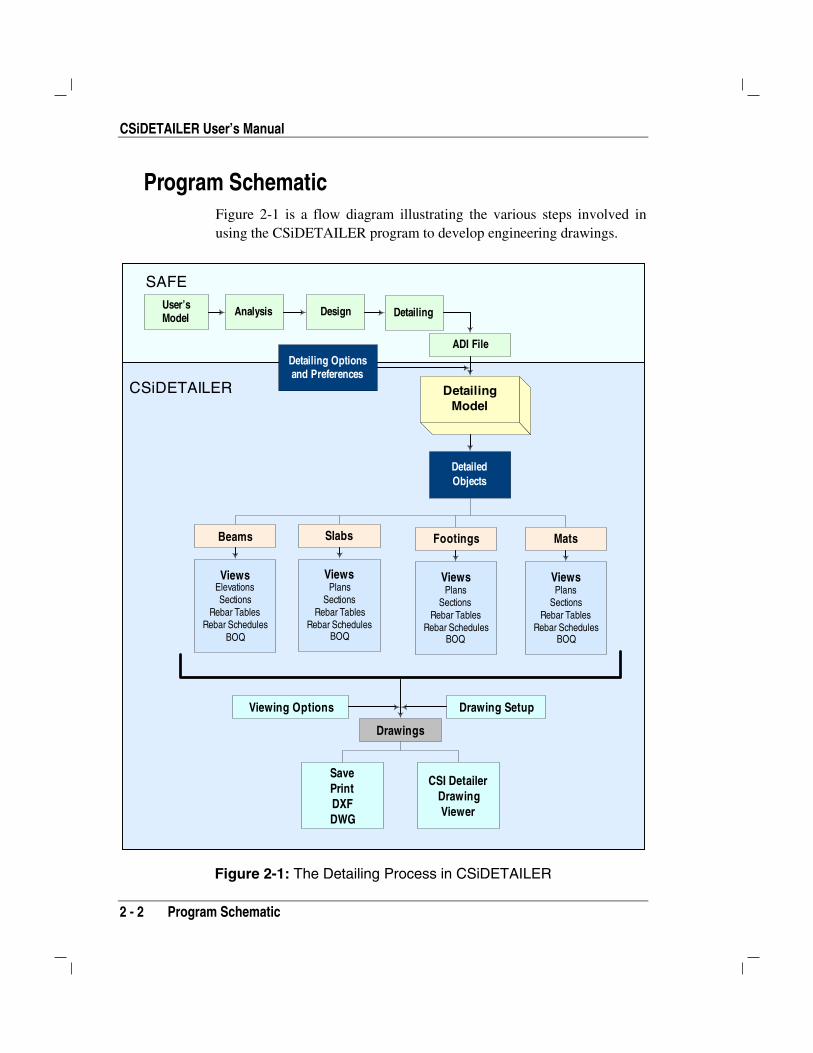
Program Schematic Figure 2-1 is a flow diagram illustrating the various steps involved inusing the CSiDETAILER program to develop engineering drawings.
User’sModel Analysis Design
Detailing Optionsand Preferences
DetailingModel
DetailedObjects
Slabs Footings Mats
ViewsPlans
SectionsRebar Tables
Rebar SchedulesBOQ
ViewsPlans
SectionsRebar Tables
Rebar SchedulesBOQ
ViewsPlans
SectionsRebar Tables
Rebar SchedulesBOQ
Drawings
SavePrintDXFDWG
ADI File
SAFE
Viewing Options Drawing Setup
CSI DetailerDrawingViewer
Beams
ViewsElevationsSections
Rebar TablesRebar Schedules
BOQ
CSiDETAILER
Detailing
Figure 2-1: The Detailing Process in CSiDETAILER

Chapter 2 Program Overview
General Process 2 - 3
Input required for the detailing model consists of the output data fromSAFE’s design model and the options and preferences. Those prefer-ences can be set from within the analysis and design package (i.e.,SAFE) or from within CSiDETAILER. CSiDETAILER output consistsof detailed beam objects, detailed slab objects, detailed footing objectsand detailed mat objects. The available detailed objects depend on thedata from the structural analysis and design program. Various views canbe generated for the detailed objects. The views are placed on the draw-ings and can be printed directly or exported in DXF and DWG formats.
Note: It is recommended that the detailing preferences be set in SAFEbefore performing the detailing. Use the Detailing menu > Main Detail-ing Preferences command to set the required parameters.
General Process The basic process for generating engineering drawings using CSiDE-TAILER involves using the output generated by SAFE and then using avariety of forms to set options and preferences to guide the detailingprocess. After the detailer has been activated, various views are added tothe drawings and arranged automatically. The views and preferences canbe altered by the user as required. The final outputs can then be sent to aprinter, or exported in DXF or DWG format for use by AutoCAD.
The following list identifies the basic process for using CSiDETAILER.
1. Prepare the input to CSiDETAILER. As indicated previously,CSiDETAILER generates detailed engineering drawing based on theoutput from SAFE. Thus, to begin the detailing process, prepare astructural model and run an analysis and design.
2. Set various preferences. Set the detailing preferences, drawing size,symbol notations, and view placement options using the Detailingmenu in SAFE.
a. Specify the code and other parameters that guide the detail-ing process. Click the Detailing menu > Main Detailing Pref-erences command in SAFE to access the Detailing Preferencesform. Use the form to specify the design code, the standard to be
CSiDETAILER User’s Manual
2 - 4 General Process
applied for rebar size and shape, and the rebar mark type for thevarious design objects.
Number Format button. Click this button to access the Di-mensioning Units and Formatting form. Use the form to spec-ify the units to be used on the drawings.
Slab Detailing button. Click this button to access the SlabDetailing Preferences form. Use the form to specify thescale to be used, indicate the rebar to be included, and selectthe rebar curtailment and selection rules to be used in gener-ating the slab views.
Beam Detailing button. Click this button to access the BeamDetailing Options form. Use the form to specify the scale tobe used, indicate the rebar to be included, and select the re-bar curtailment rules to be used in generating the beamviews.
Footing Detailing button. Click this button to access theFooting Detailing Options form. Use the form to specify thescale to be used, indicate the rebar to be included, and selectthe rebar curtailment rules to be used in generating the foot-ing views.
Mat Detailing button. Click this button to access the BaseMat Detailing Preferences form. Use the form to specify thescale to be used and indicate the rebar to be included on themat views.
b. Specify the overall layout for the drawing (e.g., Engineering,Architectural, text sizes, borders, margins and so forth).Click the Detailing menu > Drawing Setup command to accessthe Drawing Setup form. Use the form to specify the drawingsize units (e.g., ANSI Engineering, ANSI Architecture, stan-dard), drawing size, drawing scale type (e.g., engineering, archi-tectural), text and symbol sizes, margins, and drawing border. Ifthe drawing size or scales have been changed, click the MatchDefault Scales to Drawing Size button to quickly and accurately

Chapter 2 Program Overview
General Process 2 - 5
adjust the options related to drawing scale and text and symbolsize.
c. Specify the scaling to be applied to views when placed ondrawings. In some cases, the views added to a drawing do not fiton the sheet. The Detailing menu > View Placement Optionscommand displays the View Placement Options form. Use theform to specify if CSiDETAILER should scale the view to fit thesheet, leave the view as is so that the view is to scale, or dividethe view across the drawing.
3. Activate CSiDETAILER. Click the Detailing menu > Start De-tailer command to activate CSiDETAILER. As the program detailsthe model, progress will be shown on the Detailing Status form.When the detailing is complete, the program will automatically gen-erate all possible drawings and add them to the project file.
4. Specify the title block text. Click the File menu > Project Infor-mation command to access the Project Information form. Use theform to specify the project related information to be used in the titleblock of all drawings in the project file. Options exist to use the in-formation in new title blocks (i.e., newly added drawings) or to up-date all title blocks on all drawings in the project file.
5. Set the layers for export to .DXF or DWG file format. Click theOptions menu > Define View Layers command to access the LayerList form. Use the form to Add, Modify, or Delete layer names. Thelayer names are the layer names that will be used in the exportedDXF or DWG format file.
6. Specify the colors, line weights, and line types for plotting thedrawings and assign objects to layers. Click the Options menu >Drawing View Options command to access the Drawing View Op-tions form. Use the various options on the six tabs (General,Slab/Mat Plan, Slab/Mat Sections, Beams, Footings, Tables) tospecify color, weight (e.g., line width or font size), and type (e.g.,dash-dot-dot for lines or bold italic for text) for the various entitiesused to illustrate the views and tables during onscreen viewing or forprinted output. Each tab has a display area listing the various entitiesthat can be generated. Highlight an entity in the list and then set the

CSiDETAILER User’s Manual
2 - 6 General Process
display options. Each tab also has a Layer for DXF/DWG Exportdrop-down list. Select the entity in the display area, the display op-tions and, if necessary, adjust the layer name in the Layer forDXF/DWG Export drop-down list to specify the layer on which theselected item will appear when the project file is exported to a DXFor DWG format file. After the viewing options have been set, theyremain in effect until they are changed and will apply the next timethe project file is opened.
7. Review the generated drawings and make the necessary changes;refresh the drawings so that the changes can be viewed onscreen.Use the Edit, Drawing, and Tables menu commands as described inthis manual to work with the drawings to achieve the desired result.
Note: Views must be selected before any operation can be per-formed on them or with them. Select a single view by clicking on it.Select multiple views by drawing a window around them or clickingthe views one by one; it is not necessary to hold down the Shift keyto make multiple selections.
Click the View menu > Refresh View command to update the on-screen display if changes are made to preferences, options, the titleblock or arrangement of views if the program does not automaticallyperform the update.
Note: The user is responsible for thoroughly examining the CSiDE-TAILER-generated drawings and, if necessary, refining them asneeded.
8. If the drawings are satisfactory, print a hard copy. Click the Filemenu > Print Drawings command to display the Print Drawingsform. Use the form to specify the printer, the paper size, the orienta-tion, and the drawings to be printed (current, all, or selected).
9. If the drawings need additional refinement, export them to anAutoCAD/CAD compatible format. Click the File menu > ExportDrawings command to display the Export Drawings form. Use theform to specify the format for the export and the drawings to be ex-ported (current, all, or selected).

Chapter 2 Program Overview
Analysis Model and Detailing 2 - 7
Note: If the analysis and design model is changed (unlocked) inSAFE, the Detailer when accessed will display the Modification Alertform. To retain the previous detailing options and drawings, chooseRetain Current Drawings and Options option. Select the Rerun De-tailing and Update Drawings option for the detailer to rerun detailingand update drawings according to the new design results and userpreferences. The various views placed on drawings by the user willnot be affected. Select the Rerun Detailing and Generate New Draw-ings option to regenerate new drawings according to the new designoutput and preferences. All previously set preferences and informa-tion will be lost when using this option.
Analysis Model and DetailingThe procedure in the previous section describes the overall process ofdetailing using SAFE and CSiDETAILER. When a new model is de-tailed, new drawings are generated according to the options and prefer-ences set using the Detailing menu in SAFE. If no such preferences areset by the user, all drawings are generated with the default options, whichcan be accessed using the Detailing menu > Main Detailing Preferencecommand in SAFE. After the generation of drawings, the detailing pref-erences can be modified using the Option menu > Main DetailingPreference command in CSiDETAILER. After the preferences havebeen set in CSiDETAILER, the detailing needs to be rerun for thechanges to take effect.
All viewing and detailing options set, along with various other modifica-tion that have been made to the drawings in CSiDETAILER, are savedby the program. When Detailer is revisited, the program “remembers”the changes made by the user and displays the drawings accordingly.
If the analysis and design model is changed in SAFE or if the detailingpreferences are modified using the Detailing menu > Main DetailingPreference command in SAFE, the Detailer, when it is accessed again,will prompt the user that changes have been made, listing all the changeson the Modification Alert form. The user can then select to retain thepreviously generated drawings, rerun detailing and update the drawings,or rerun detailing and generate new drawings. The second option is use-

CSiDETAILER User’s Manual
2 - 8 Analysis Model and Detailing
ful if the user wishes to retain previously defined view options, such asthe addition or modification of section lines. This option is also appropri-ate if changes are made to the loading on the analysis model. However,if the geometry of the analysis model is changed, it is recommended thatthe detailing be rerun and the drawings be regenerated.
3 - 1
Chapter 3
Terminology, the GUI and Menu Commands
This chapter identifies key terminology used in the program; describesthe graphical user interface (GUI) that is used to generate, modify, printand export the drawings; and summarizes the various menu commandsused to enable the features offered by CSiDETAILER.
Terminology Drawings. The word “drawing” as used herein is analogous to a
common drawing sheet. The drawings are displayed on the mainCSiDETAILER screen, or drawing viewer. After the detailing modelhas been run, views of beam, slab, footing and mat detailing alongwith tables and general notes can be added to a drawing(s), where theviews, tables, and notes can be arranged. Drawings can be saved ininternal format, printed, or exported as DXF files or DWG files foruse in AutoCAD or other CAD software.
CISCOLCISDetailerCISCOLCISCOLCSiDETAILER™CISCOLCISCOLCISDetailerCISDetailerCISCOLCISCOLCISCOLCISCOLCSiDETAILER™

CSiDETAILER User’s Manual
3 - 2 Terminology
Note: A single drawing can consist of views from more than onestructural member. Several drawings can be created from a singlestructural analysis and design model.
Detailing Options and Preferences. The detailing options andpreferences guide the detailing process. Use them to specify anycode to be applied during the detailing process, the scale for com-pleting the detailing, and various options related to rebar selection,curtailment, placement and display.
Detailed Objects. The detailing process generates detailed beamobjects, detailed slab objects, detailed footing objects and detailedmat objects, assuming that those objects are included in the structuralanalysis and design model. On the basis of user selection, views ofthose detailed objects are added to the drawings, which are displayedon the drawing viewer.
Views. Depending on user selection, views of the detailed objectscan be added to the drawings. The views can be assigned viewingproperties. Similar views of the same object may be assigned differ-ent viewing properties. The program retains the viewing propertiesof each drawing and each time the detailing is rerun, the views areregenerated/updated using the assigned viewing properties.
Several object views can be placed on a drawing. Conversely, thesame view can be placed on several drawings. The views may in-clude plans, sections, elevations, rebar tables and lists of drawings.Views can be added, deleted, copied, pasted, and arranged.
Tables. Tables are special views that can also be added to drawings.The appearance of the table can be controlled by user-specifiedproperties. The tables include rebar tables and rebar schedules for allor selected Detailed Objects. Tables can be added, deleted, moved,copied, pasted and resized just like any other view.
Tabulated Output. Some of the detailing information/output gener-ated by CSiDETAILER can be viewed in tabulated form. Thosetabulated results can then be exported to other applications. Thetabulated outputs can include BOQs and summaries of the project inaddition to rebar tables and schedules.

Chapter 3 Terminology, the GUI and Menu Commands
Graphical User Interface 3 - 3
Entities. Views consist of entities. For example, a simple slab planas drawn on any conventional drawing sheet may consist ofgridlines, a slab outline, dimension lines, columns, beam lines, toprebar, bottom rebar, or rebar calls. Each one of them is referred to asan entity in the detailing model. Viewing properties for different en-tities can be set independently. Those properties include line type,color and thickness, and text size and color.
Graphical User Interface Figure 3-1 shows the CSiDETAILER graphical user interface, includingthe working area or drawing viewer, the drawing explorer, menus andtoolbars.
Figure 3-1: CSiDETAILER Main Interface
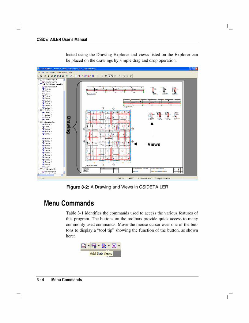
The drawing viewer shows the current drawing and the views added tothe drawing. A single drawing at a time is displayed on the drawingviewer, although several drawings can be saved in the same file, or proj-ect. Figure 3-2 shows the drawing viewer displaying a drawing, withviews that can be generated by CSiDETAILER. Drawings can be se-
ToolbarsMenu Bar
Title Bar
Status Bar
Working Area or Drawing Viewer
Drawing Explorer
CSiDETAILER User’s Manual
3 - 4 Menu Commands
lected using the Drawing Explorer and views listed on the Explorer canbe placed on the drawings by simple drag and drop operation.
Figure 3-2: A Drawing and Views in CSiDETAILER
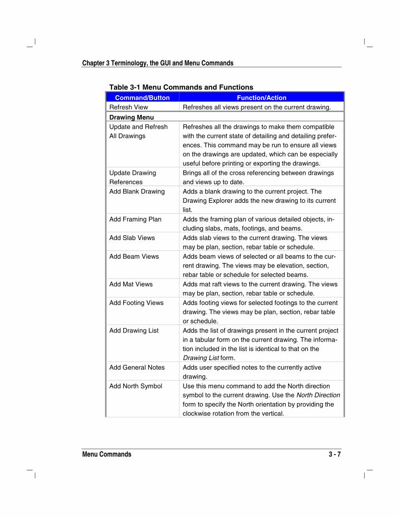
Menu Commands Table 3-1 identifies the commands used to access the various features ofthis program. The buttons on the toolbars provide quick access to manycommonly used commands. Move the mouse cursor over one of the but-tons to display a “tool tip” showing the function of the button, as shownhere:
Draw
ing
Views

Chapter 3 Terminology, the GUI and Menu Commands
Menu Commands 3 - 5
Table 3-1 Menu Commands and Functions Command/Button Function/Action
File menu
Save Project Saves the current project. All the detailing options andpreferences set by the user are also saved by the pro-gram.
Export Drawings Activates the Export Drawings form to export current,all or selected drawings to DXF or DWG format.
Print Drawing Sends all or selected drawings to a printer or plotter.
Print Tables Sends selected or all tables to a printer or plotter.
Project Information Activates the Project Information form where generalinformation regarding the current project can be speci-fied. This information can be displayed in the titleblock of all drawings in the project.
Return to SAFE Exits CSiDETAILER after saving all changes made bythe user, and returns to SAFE
Edit menu Undo Undoes the last action. Unlimited undo of actions
performed in the drawing viewer is provided inCSiDETAILER. Changes made on a form other thanthe drawing viewer cannot be undone.
Cut Cuts the selected view(s) from a drawing and places iton the system Clipboard.
Copy Copies the selected view(s) and places it on the sys-tem Clipboard.
Paste Pastes items on the system Clipboard in to the currentDrawing.
Delete Deletes the currently selected view(s).
Edit Drawing Title Activates the Title Block Editing mode. Click on thetitle block area of a drawing to edit the text in each
cell. Click on the Select button to exit the Title
Block Editing mode.
Edit Slab SectionLines
Activates the Section Line Editor form. Slab sectionlines can be edited graphically or numerically on thisform. Additional Section Lines can also be defined.

CSiDETAILER User’s Manual
3 - 6 Menu Commands
Table 3-1 Menu Commands and Functions Command/Button Function/Action
Edit Mat Section Lines Activates the Section Line Editor form. Mat sectionlines can be edited graphically or numerically on thisform. Additional Section Lines can also be defined.
Edit Beam SectionLines
Activates the Section Line Editor form. Beam sectionlines can be edited graphically or numerically on thisform. Additional section lines can also be defined.
Edit Selected ViewProperties
Opens the View Properties form. Use the form tospecify properties such as view location, scaling, par-ent object and caption for views on drawings.
Edit Drawing List Activates the Drawing List form. The form displays thelist of all drawings present in the project. Use the formto edit the drawing title, drawing number, revisionnumber, and issue date.
Edit General Notes Activates the General Notes form. Use the form to editthe notes that have been added to the drawings.
Check and EditReinforcement
Activates the Check and Edit Reinforcement form. Theform displays the minimum, provided and requiredarea of steel for various detailed objects. The steelamount and reinforcement location can be edited bythe user.
View menu Window Zoom Zooms into part of the drawing by dragging the mouse
while holding down the left mouse button to “window”around the area of interest.
Restore Full View Resets the view such that the entire drawing is visible.
Previous Zoom Sets zoom to the last magnification.
Zoom In One Step Increases the zoom using a default increment.
Zoom Out One Step Decreases the zoom using a default increment.
Pan Activates the pan mode. Use this command and thenclick on the view in the drawing viewer. Hold the leftmouse button down and drag the view to change thedisplay to portions of the drawing that currently are notin view.
Select All Selects all items on the current drawing.
Clear Selection Deselects the currently selected items.
Chapter 3 Terminology, the GUI and Menu Commands
Menu Commands 3 - 7
Table 3-1 Menu Commands and Functions Command/Button Function/Action
Refresh View Refreshes all views present on the current drawing.
Drawing Menu Update and RefreshAll Drawings
Refreshes all the drawings to make them compatiblewith the current state of detailing and detailing prefer-ences. This command may be run to ensure all viewson the drawings are updated, which can be especiallyuseful before printing or exporting the drawings.
Update DrawingReferences
Brings all of the cross referencing between drawingsand views up to date.
Add Blank Drawing Adds a blank drawing to the current project. TheDrawing Explorer adds the new drawing to its currentlist.
Add Framing Plan Adds the framing plan of various detailed objects, in-cluding slabs, mats, footings, and beams.
Add Slab Views Adds slab views to the current drawing. The viewsmay be plan, section, rebar table or schedule.
Add Beam Views Adds beam views of selected or all beams to the cur-rent drawing. The views may be elevation, section,rebar table or schedule for selected beams.
Add Mat Views Adds mat raft views to the current drawing. The viewsmay be plan, section, rebar table or schedule.
Add Footing Views Adds footing views for selected footings to the currentdrawing. The views may be plan, section, rebar tableor schedule.
Add Drawing List Adds the list of drawings present in the current projectin a tabular form on the current drawing. The informa-tion included in the list is identical to that on theDrawing List form.
Add General Notes Adds user specified notes to the currently activedrawing.
Add North Symbol Use this menu command to add the North directionsymbol to the current drawing. Use the North Directionform to specify the North orientation by providing theclockwise rotation from the vertical.
CSiDETAILER User’s Manual
3 - 8 Menu Commands
Table 3-1 Menu Commands and Functions Command/Button Function/Action
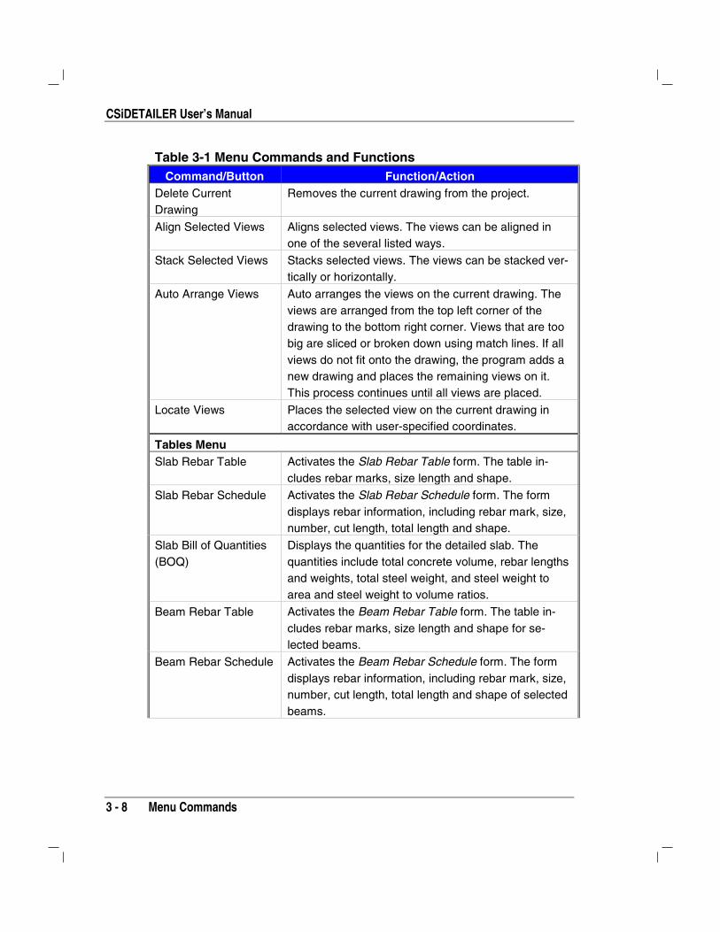
Delete CurrentDrawing
Removes the current drawing from the project.
Align Selected Views Aligns selected views. The views can be aligned inone of the several listed ways.
Stack Selected Views Stacks selected views. The views can be stacked ver-tically or horizontally.
Auto Arrange Views Auto arranges the views on the current drawing. Theviews are arranged from the top left corner of thedrawing to the bottom right corner. Views that are toobig are sliced or broken down using match lines. If allviews do not fit onto the drawing, the program adds anew drawing and places the remaining views on it.This process continues until all views are placed.
Locate Views Places the selected view on the current drawing inaccordance with user-specified coordinates.
Tables Menu Slab Rebar Table Activates the Slab Rebar Table form. The table in-
cludes rebar marks, size length and shape.
Slab Rebar Schedule Activates the Slab Rebar Schedule form. The formdisplays rebar information, including rebar mark, size,number, cut length, total length and shape.
Slab Bill of Quantities(BOQ)
Displays the quantities for the detailed slab. Thequantities include total concrete volume, rebar lengthsand weights, total steel weight, and steel weight toarea and steel weight to volume ratios.
Beam Rebar Table Activates the Beam Rebar Table form. The table in-cludes rebar marks, size length and shape for se-lected beams.
Beam Rebar Schedule Activates the Beam Rebar Schedule form. The formdisplays rebar information, including rebar mark, size,number, cut length, total length and shape of selectedbeams.

Chapter 3 Terminology, the GUI and Menu Commands
Menu Commands 3 - 9
Table 3-1 Menu Commands and Functions Command/Button Function/Action
Beam Bill of Quantities(BOQ)
Displays the quantities for the detailed beams. Thequantities include total concrete volume, rebar lengthsand weights, total steel weight, and steel weight toarea and steel weight to volume ratio.
Mat Rebar Table Activates the Mat Rebar Table form. The table in-cludes rebar marks, size length and shape.
Mat Rebar Schedule Activates the Mat Rebar Schedule form. The form dis-plays rebar information, including rebar mark, size,number, cut length, total length and shape.
Mat Bill of Quantities(BOQ)
Displays the quantities for the detailed mat. The quan-tities include total concrete volume, rebar lengths andweights, total steel weight, and steel weight to areaand steel weight to volume ratios.
Footing Rebar Table Activates the Footing Rebar Table form. The table in-cludes rebar marks, size length and shape for se-lected footings.
Footing RebarSchedule
Activates the Footing Rebar Schedule form. The formdisplays rebar information, including rebar mark, size,number, cut length, total length and shape for selectedfootings.
Footing Bill ofQuantities (BOQ)
Displays the quantities for the detailed footing. Thequantities include total concrete volume, rebar lengthsand weights, total steel weight, and steel weight toarea and steel weight to volume ratio.
Options menu Main DetailingPreferences
Activates the Detailing Preferences form. Use the formto specify the number format, detailing code, rebartype and shape, and specific object detailing prefer-ences.
Drawing Setup Activates the Drawing Setup form. Use the form to setthe drawing scale, size, text and symbol sizes, andmargins.
Drawing View Options Activates the View Options form. Use the form to setthe line thickness and color and text size and color forvarious view items.

CSiDETAILER User’s Manual
3 - 10 Menu Commands
Table 3-1 Menu Commands and Functions Command/Button Function/Action
Drawing Symbols Activates the Drawing Items Symbols form. Use theform to select drawing symbols for various drawingitems. Those items include view captions, dimensionline arrows, section marks, and other symbols.
Define View Layers Activates the Layer List form. Use the form to set layerproperties for a drawing(s) when it is exported to aCAD-compatible file format.
View PlacementOptions
Activates the View Placement Options form. Use theform to set rules for generating new drawings andplacing new views on drawings.
Help menu Search for Help on Accesses the CSiDETAILER .html Help. The Help
provides hyperlinked information about the variousmenu commands and forms used by the program. TheHelp has a search capability, index, and contents.
CSI on the Web Accesses the CSI web site, where additional informa-tion about CSI and its products is available.
About CSiDETAILER Provides various information about CSiDETAILER,including the version number and release date.
4 - 1
Chapter 4
Set Up the Detailing Model
Input to the detailing model consists of output data from SAFE and de-tailing options and preferences set by the user. This chapter identifiessome items to be considered with respect to how the design model isgenerated to ensure that the design program output can be used effec-tively by CSiDETAILER in generating quality engineering drawings. Italso identifies the detailing options and preferences that should be set toinitiate the detailing process and the options available for setting up thedrawings.
X and Y Strips in the Design Model SAFE is capable of designing slabs irrespective of the width and locationof the design strips. However, detailing of the slabs as performed byCSiDETAILER is directly linked to the proper use of the design strips.The spacing, number and location of rebar are determined for each de-sign strip independently based on the reinforcement computed by SAFE.Rebar are placed within the strip’s width and length. Therefore, if the de-
CISCOLCISDetailerCISCOLCISCOLCSiDETAILER™CISCOLCISCOLCISDetailerCISDetailerCISCOLCISCOLCISCOLCISCOLCSiDETAILER™
CSiDETAILER User’s Manual
4 - 2 X and Y Strips in the Design Model
sign strips are too narrow or too wide, the rebar arrangement may not beas desired.
Also, if gaps exist between the design strips or if the design strips over-lap, the resulting rebar layout may not be appropriate or even complete.Also, if the detailing is based on code specified rules, CSiDETAILERcategorizes strips as column strips or middle strips based on the locationof columns within the strip width. The detailing rules are then appliedappropriately after the strips have been categorized. If the strips have notbeen defined properly, it may not be possible for the program to deter-mine the column and middle strips correctly. In such cases it is recom-mended that the “Computed Steel” option on the Slab Detailing Prefer-ence form be used. The following general guideline may be used for set-ting up the strips.
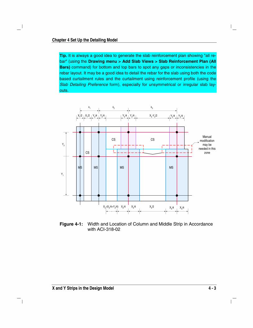
1. If possible, the design strip layout should be consistent with the defi-nition of column strip and middle strip as provided in ACI-318-02.Those rules are illustrated in Figure 4-1
2. The design strips should not overlap and there should be no gapsbetween the design strips. The design strips should not be too narrowor too wide. The minimum width should be more than approximately3 feet (1.0 m).
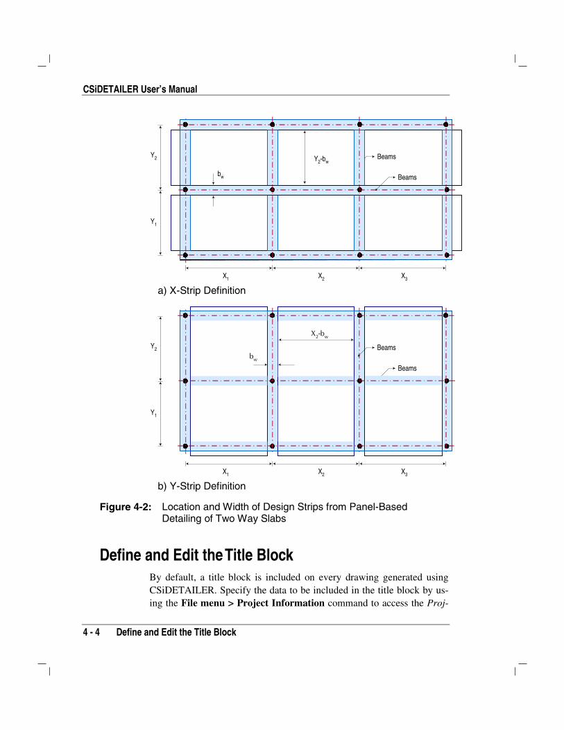
3. If two-way slabs supported on beams or walls are to be detailed inpanels rather than column and middle strips, the design strips can beplaced edge to edge between beams (Figure 4-2).
4. If the design strips are terminated in the middle of a span or over acolumn, the longitudinal rebar provided by the program will also beterminated at the end of the strip. In such a case, some manual modi-fication of rebar layout may be needed in those regions.
5. The program automatically adjusts the rebar and their extent if anopening crosses a design strip partially or fully. However, it is betterto arrange the design strips around the openings if possible.
Important: The design strips must be arranged properly for the program to de-tail the slab rebar effectively. Verify the drawings generated by CSiDETAILER.
Chapter 4 Set Up the Detailing Model
X and Y Strips in the Design Model 4 - 3
Tip. It is always a good idea to generate the slab reinforcement plan showing "all re-bar" (using the Drawing menu > Add Slab Views > Slab Reinforcement Plan (AllBars) command) for bottom and top bars to spot any gaps or inconsistencies in therebar layout. It may be a good idea to detail the rebar for the slab using both the codebased curtailment rules and the curtailment using reinforcement profile (using theSlab Detailing Preference form), especially for unsymmetrical or irregular slab lay-outs.
Y1
Y2
x1 x2 x3
X1/2 X1/2 Y2/4 Y2/4 Y2/4 Y2/4 Y2/4 Y2/4X3-Y2/2
X2/4 X3/4 X3/4X3/2 X3/4
X2-(X2/4+Y2/4)
MS MS MS MS
CSCS
CS
Manualmodification
may beneeded in this
zone
Figure 4-1: Width and Location of Column and Middle Strip in Accordancewith ACI-318-02
CSiDETAILER User’s Manual
4 - 4 Define and Edit the Title Block
Beams
Beams
bw
Y2-bw
X1 X2 X3
Y2
Y1
a) X-Strip Definition
bw
X2-bw
Beams
Beams
X1 X2 X3
Y2
Y1
b) Y-Strip Definition
Figure 4-2: Location and Width of Design Strips from Panel-BasedDetailing of Two Way Slabs
Define and Edit the Title Block By default, a title block is included on every drawing generated usingCSiDETAILER. Specify the data to be included in the title block by us-ing the File menu > Project Information command to access the Proj-

Chapter 4 Set Up the Detailing Model
Define and Edit the Title Block 4 - 5
ect Information form. As shown in Figure 4-3, the Project Informationform has options to record the data typically included in a title block, in-cluding a company logo. Record or change the data on the Project In-formation form by typing directly in the edit boxes. Then choose to up-date existing drawings or apply the updates to new drawings only. Thedata recorded on the Project Information form will be used in the titleblocks of all drawings in the project file, unless the data is changed on adrawing-by-drawing basis using the Edit menu > Edit Drawing Titlecommand.
Click the Edit menu > Edit Drawing Title command to enable the titleblock editing mode and directly edit the title block. Click the commandand then click the appropriate cell in the title block to make the necessarychanges. This command changes the current title block without affectingthe title blocks of any other drawings in the project file.
Tip. To replace the default CSI Logo on the drawing with another logo, replace the“Company Logo.jpg” file in the application directory with a valid .bmp or .jpg formatfile.
Figure 4-3: Project Information Form

CSiDETAILER User’s Manual
4 - 6 Set the Code and Other Preferences
Note: To omit the title block from a drawing, uncheck the Show TitleBlock check box on the Drawing Setup form, which is displayed using theOptions menu > Drawing Setup command.
Set the Code and Other Preferences CSiDETAILER uses preferences and options to guide the detailing proc-ess, including a detailing code, rebar sizes, rebar shapes, and rebar marktypes, where applicable. Use the Detailing Preferences form shown inFigure 4-4 to specify the code and preferences. Access the DetailingPreferences form by clicking the Options menu > Main DetailingPreferences command.
Figure 4-4: Detailing Preferences Form
If the Detailing Preferences are changed using the Detailing menu com-mand in SAFE, the Detailer when activated will notify the user thatchanges have been made to the detailing preferences. The user may thenchoose to rerun the detailing and generate new drawing in line with thenew preferences or to keep the previously generated drawings. If theDetailing Preferences are changed using the Options menu in CSiDE-TAILER, the program will prompt the user to rerun the detailing to up-date drawings using the newly set preferences.
Chapter 4 Set Up the Detailing Model
Set the Code and Other Preferences 4 - 7
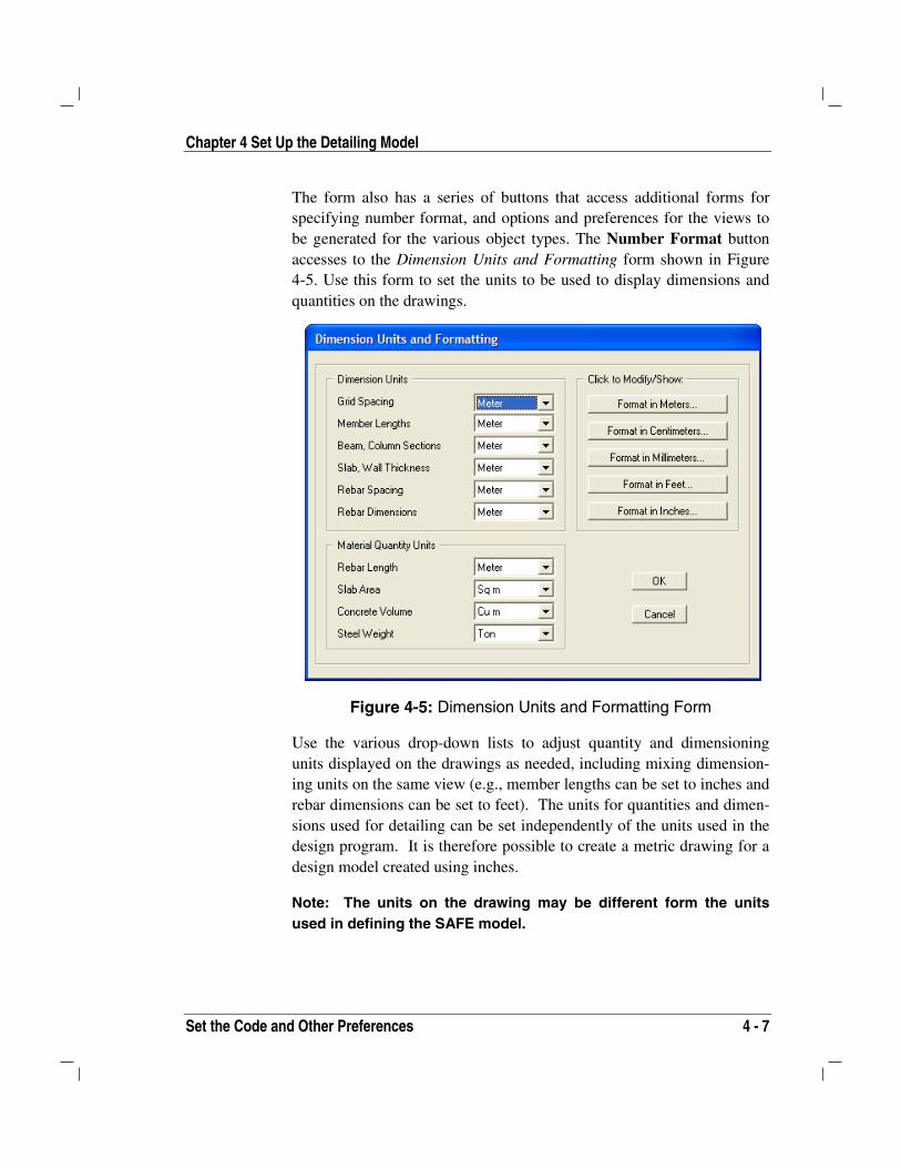
The form also has a series of buttons that access additional forms forspecifying number format, and options and preferences for the views tobe generated for the various object types. The Number Format buttonaccesses to the Dimension Units and Formatting form shown in Figure4-5. Use this form to set the units to be used to display dimensions andquantities on the drawings.
Figure 4-5: Dimension Units and Formatting Form
Use the various drop-down lists to adjust quantity and dimensioningunits displayed on the drawings as needed, including mixing dimension-ing units on the same view (e.g., member lengths can be set to inches andrebar dimensions can be set to feet). The units for quantities and dimen-sions used for detailing can be set independently of the units used in thedesign program. It is therefore possible to create a metric drawing for adesign model created using inches.
Note: The units on the drawing may be different form the unitsused in defining the SAFE model.

CSiDETAILER User’s Manual
4 - 8 Set the Code and Other Preferences
Use the Format in {Units} buttons to specify the formatting for each ofthe unit types.
Click the appropriate button to specify slab, beam, footing and mat de-tailing preferences. Tables 4-1 through 4-4 list the various preferencesand options that can be set using the Slab Detailing Preferences, BeamDetailing Options, Footing Detailing Preferences, and Base Mat De-tailing Preferences forms, respectively.
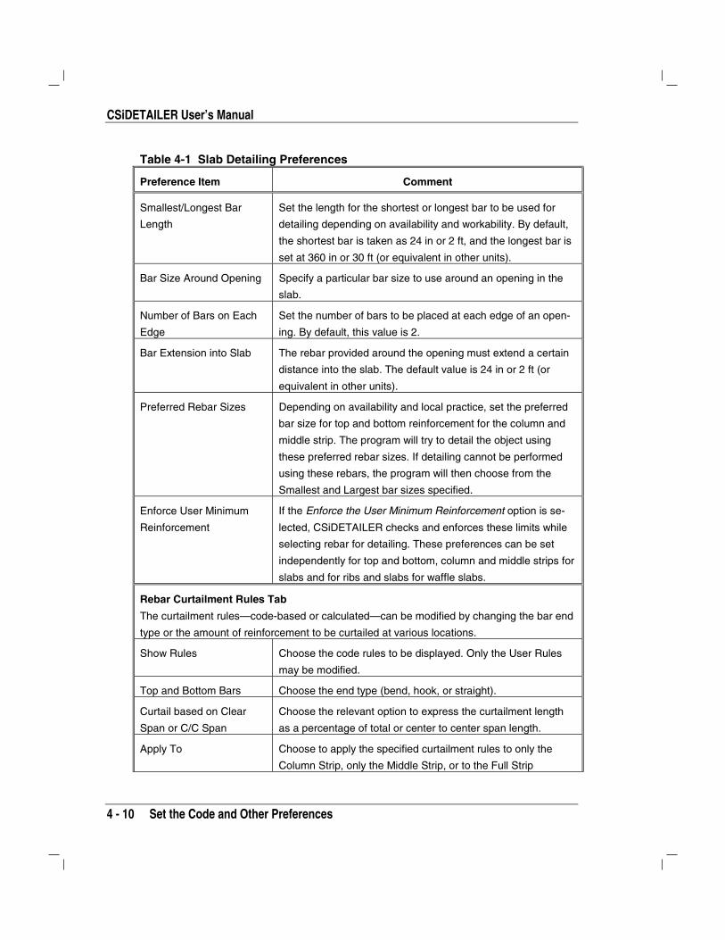
Table 4-1 Slab Detailing Preferences
Preference Item Comment
General and Display Tab
Rebar Curtailment
Options
Choose curtailment rules (defined under rebar curtailment
rules tab) or curtail rebar using the computed area of steel. If
rules are selected, the Detailer locates the columns, slab out-
lines, column strips, and middle strips by examining the ge-
ometry of the model and applying the code provisions. If cur-
tailment is calculated from the computed area of steel, the
detailing model follows the reinforcement distribution profiles
computed by the design program and then adds embedment
and development lengths.
Detailing Mode The Detailing Mode is activated when the Curtail bars using
the computed Area of Steel option is selected. The Detailing
All Bars option will perform detailing in the usual way, detailing
all the bars on the slab plan. The Detail Bars Above Typical
option will detail only the bars that the user has specified
above the typical detailing. The preferences for selection of
such bars can be specified using the options listed in the Typi-
cal Bars area of the form.
Default Slab View Scales
for New Drawings
Set the slab plan scale and the section detail scale in each
direction. These are the default scales for the views generated,
which may be changed using the Edit menu > Edit Selected
View Properties command. These scales have a different
meaning from those set using the Options menu > Drawing
Setup command. The scales set using that command apply to

Chapter 4 Set Up the Detailing Model
Set the Code and Other Preferences 4 - 9
Table 4-1 Slab Detailing Preferences
Preference Item Comment
size text, title block, arrowheads, and the like. Also, the scales
set using the Drawing Setup command do not affect the views
on existing drawings. Scales for individual views can be set
using the Edit menu > Edit Selected View Properties com-
mand.
Default Sections Set the number of default sections in each direction. This
number is used when detailing is run for the first time. The
number and location of the marked sections can be changed
using the Section Line Editor (see Chapter 5).
Rebar Calls Select the amount of information to be displayed for each re-
bar call. The Sample Rebar Call display will be updated with
every selection.
Rebar Selection Tab
Smallest Bar Size The minimum size of reinforcing bar used for slab detailing.
Any bar can be set as the minimum size depending on the
availability of bars.
Largest Bar Size The largest size of reinforcing bar used for slab detailing. This
size should be larger than or equal to the smallest bar size
Minimum/Maximum
Number of Bars
The number of bars in a single design strip. Restrict the num-
ber of bars used for reinforcing detailing by specifying the
minimum/maximum number of bars. The default value for the
minimum number is 2, and the maximum number is 100.
Maximum Excess Area Usually during detailing, some excess area of reinforcing is
used. The detailing model can limit the excess area to a user-
defined value by choosing appropriate bar sizes within the
specified bar size and spacing limitations. The value is ex-
pressed as a percentage of required area, and by default, is
set at 20%. Set this property to make the design more eco-
nomical.
Minimum/Maximum
Spacing of Bars
The minimum and maximum bar spacing limitations are de-
fined in the structural design codes. The values set here will
override the code specified values.
CSiDETAILER User’s Manual
4 - 10 Set the Code and Other Preferences
Table 4-1 Slab Detailing Preferences
Preference Item Comment
Smallest/Longest Bar
Length
Set the length for the shortest or longest bar to be used for
detailing depending on availability and workability. By default,
the shortest bar is taken as 24 in or 2 ft, and the longest bar is
set at 360 in or 30 ft (or equivalent in other units).
Bar Size Around Opening Specify a particular bar size to use around an opening in the
slab.
Number of Bars on Each
Edge
Set the number of bars to be placed at each edge of an open-
ing. By default, this value is 2.
Bar Extension into Slab The rebar provided around the opening must extend a certain
distance into the slab. The default value is 24 in or 2 ft (or
equivalent in other units).
Preferred Rebar Sizes Depending on availability and local practice, set the preferred
bar size for top and bottom reinforcement for the column and
middle strip. The program will try to detail the object using
these preferred rebar sizes. If detailing cannot be performed
using these rebars, the program will then choose from the
Smallest and Largest bar sizes specified.
Enforce User Minimum
Reinforcement
If the Enforce the User Minimum Reinforcement option is se-
lected, CSiDETAILER checks and enforces these limits while
selecting rebar for detailing. These preferences can be set
independently for top and bottom, column and middle strips for
slabs and for ribs and slabs for waffle slabs.
Rebar Curtailment Rules Tab
The curtailment rules—code-based or calculated—can be modified by changing the bar end
type or the amount of reinforcement to be curtailed at various locations.
Show Rules Choose the code rules to be displayed. Only the User Rules
may be modified.
Top and Bottom Bars Choose the end type (bend, hook, or straight).
Curtail based on Clear
Span or C/C Span
Choose the relevant option to express the curtailment length
as a percentage of total or center to center span length.
Apply To Choose to apply the specified curtailment rules to only the
Column Strip, only the Middle Strip, or to the Full Strip

Chapter 4 Set Up the Detailing Model
Set the Code and Other Preferences 4 - 11
Table 4-1 Slab Detailing Preferences
Preference Item Comment
Slab with Drop
Panels/Slab Without Drop
Panels
Choose to detail rebar with or without drop panels.
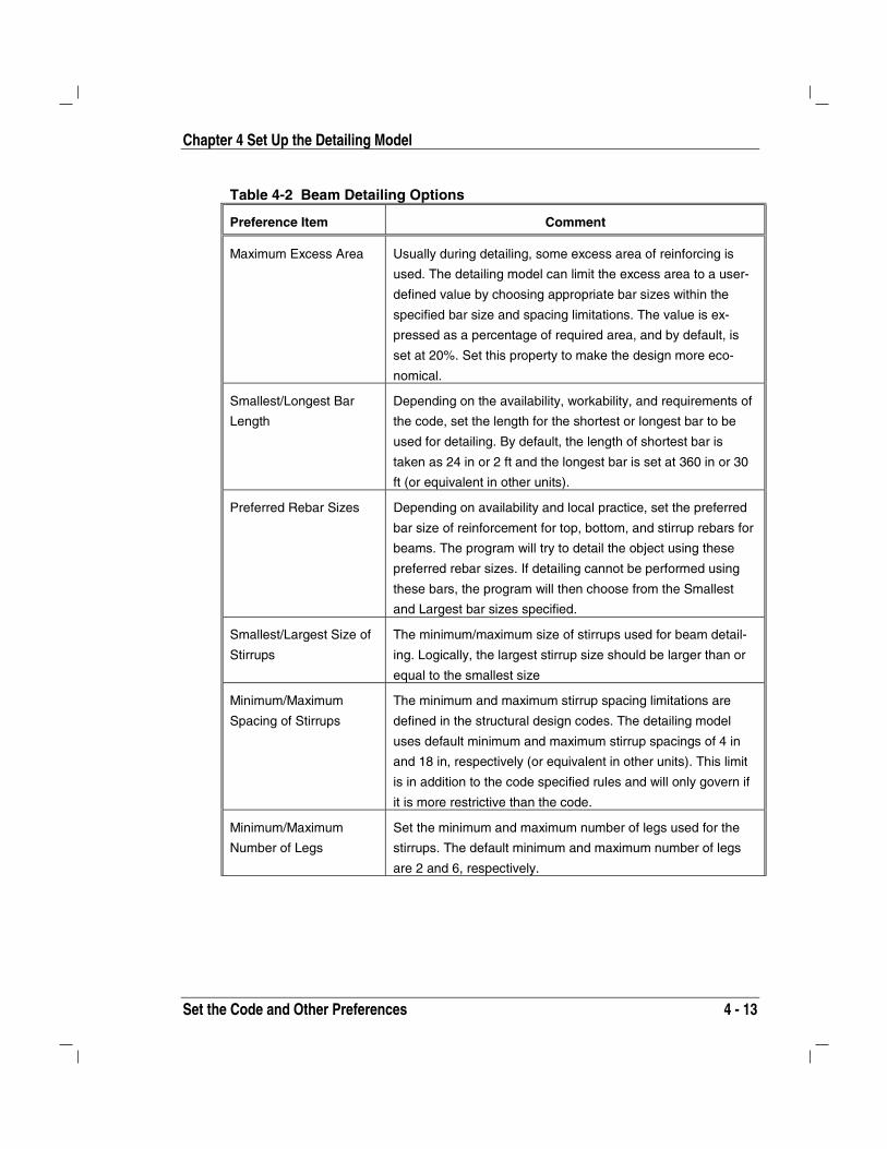
Table 4-2 Beam Detailing Options
Preference Item Comment
General and Display Tab
Rebar Curtailment
Options
Choose curtailment rules (defined under rebar curtailment
rules tab) or curtail rebar using the computed area of steel. If a
code is selected, the curtailment for the computed area of steel
also can be checked. If curtailment is calculated from the
computed area of steel, the detailing model follows the rein-
forcement distribution profiles computed by the design pro-
gram and then adds embedment and development lengths.
Also specify any hanger rebar and their number, size, curtail-
ment and overlap.
Beam View Scale Set the default beam view scale and the section detail scale.
These are the default scales for the views generated, which
may be changed using the Edit menu > Edit Selected View
Properties command. These scales have a different meaning
from those set using the Options menu > Drawing Setup
command. The scales set using that command apply to size
text, title block, arrowheads, and the like. Also, the scales set
using the Drawing Setup command do not affect the views on
existing drawings. Scales for individual views can be set using
the Edit menu > Edit Selected View Properties command.
Default Sections Set the number of default sections along each span of the
beam. This number is used when detailing is run for the first
time. The number and location of the marked sections can be
changed using the Section Line Editor (see Chapter 5).

CSiDETAILER User’s Manual
4 - 12 Set the Code and Other Preferences
Table 4-2 Beam Detailing Options
Preference Item Comment
Beams to Detail Similar beams (similar dimensions in elevation and section)
can be grouped and detailed as a single beam if the Group
Similar Beams and Detail Once option is selected. Otherwise,
the program will detail each beam independently. If the beams
are grouped and then detailed, the program generates an en-
velope detail of the beam. This means that the beam is de-
tailed for the sections that have the maximum reinforcement
from among a group and is shown as a “Master Beam.” Right
clicking the Master Beam will display the list of beams that
have been collapsed into the Master. The user can deselect
any beam from the list to detail it as an independent beam.
Rebar Calls Select the amount of information to be displayed for each re-
bar call. The Sample Rebar Call display will be updated with
every selection. Checking the Show every Stirrup check box
will display all stirrups on the beam elevation.
Rebar Selection
Smallest Bar Size The minimum size of reinforcing bar used for beam detailing.
By default, the detailing model uses #4 bars as the minimum.
Any bar can be set as the minimum size for detailing depend-
ing on the availability of bars.
Largest Bar Size The largest size of reinforcing bar used for beam detailing.
This size should be larger than or equal to the smallest bar
size.
Minimum/Maximum
Number of Bars
Restrict the number of bars used for reinforcing in the detailing
model by specifying the minimum/maximum number of bars.
The default value for the minimum number is 2 and the maxi-
mum number is 100.
Maximum Mixed Bar
Sizes
To achieve optimal detailing, the detailing model uses more
than one rebar size. Limit the number of mixed bar sizes to
save logistic, cutting and placing costs. By default, this value is
set at 2 (i.e., two different sizes of bars are used for detailing).
Chapter 4 Set Up the Detailing Model
Set the Code and Other Preferences 4 - 13
Table 4-2 Beam Detailing Options
Preference Item Comment
Maximum Excess Area Usually during detailing, some excess area of reinforcing is
used. The detailing model can limit the excess area to a user-
defined value by choosing appropriate bar sizes within the
specified bar size and spacing limitations. The value is ex-
pressed as a percentage of required area, and by default, is
set at 20%. Set this property to make the design more eco-
nomical.
Smallest/Longest Bar
Length
Depending on the availability, workability, and requirements of
the code, set the length for the shortest or longest bar to be
used for detailing. By default, the length of shortest bar is
taken as 24 in or 2 ft and the longest bar is set at 360 in or 30
ft (or equivalent in other units).
Preferred Rebar Sizes Depending on availability and local practice, set the preferred
bar size of reinforcement for top, bottom, and stirrup rebars for
beams. The program will try to detail the object using these
preferred rebar sizes. If detailing cannot be performed using
these bars, the program will then choose from the Smallest
and Largest bar sizes specified.
Smallest/Largest Size of
Stirrups
The minimum/maximum size of stirrups used for beam detail-
ing. Logically, the largest stirrup size should be larger than or
equal to the smallest size
Minimum/Maximum
Spacing of Stirrups
The minimum and maximum stirrup spacing limitations are
defined in the structural design codes. The detailing model
uses default minimum and maximum stirrup spacings of 4 in
and 18 in, respectively (or equivalent in other units). This limit
is in addition to the code specified rules and will only govern if
it is more restrictive than the code.
Minimum/Maximum
Number of Legs
Set the minimum and maximum number of legs used for the
stirrups. The default minimum and maximum number of legs
are 2 and 6, respectively.

CSiDETAILER User’s Manual
4 - 14 Set the Code and Other Preferences
Table 4-2 Beam Detailing Options
Preference Item Comment
User Minimum
Reinforcement
Specify the minimum ratio (as a percentage of the cross-
section area) for the top and bottom reinforcement. By default,
the minimum area for top and bottom reinforcement is set to
0.5% of the concrete area. If the Enforce the Minimum Ast
Limits and Enforce Preferred Size options are selected,
CSiDETAILER checks and enforces these limits while select-
ing rebar for detailing. Limits for top and bottom steel need not
be similar.
Rebar Curtailment Rules
Show Rules Choose the code rules to be used for curtailment and bending
of bars. If the User option is selected, the rules can be modi-
fied by the user.
Top and Bottom Bars Choose the end type (bend, hook, or straight) for top and bot-
tom bars. The end type for top and bottom steel need not be
similar.
Curtail based on Clear
Span or C/C Span
Choose the relevant option to express the curtailment length
as a percentage of total or center to center span length.
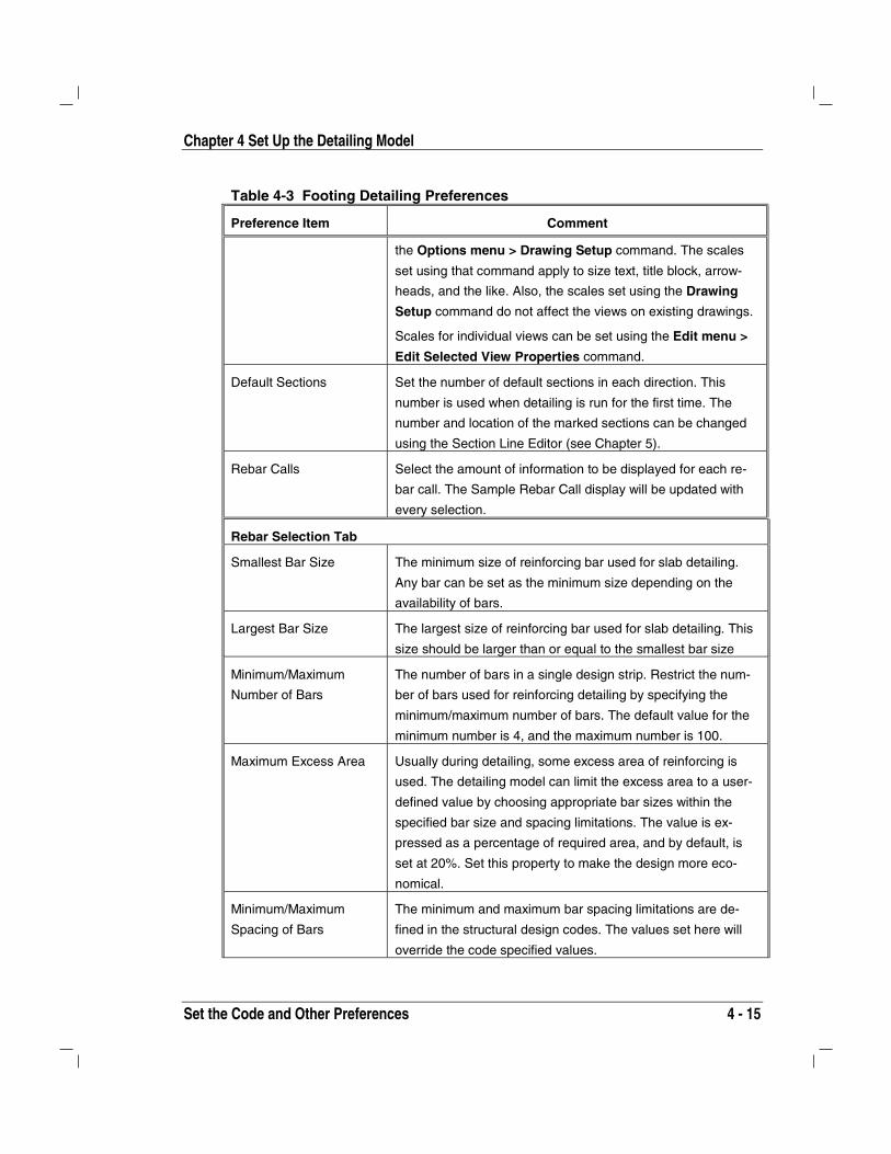
Table 4-3 Footing Detailing Preferences
Preference Item Comment
General and Display Tab
Detailing Mode Choose to detail all bars or specify to detail rebar above a
specified typical bar. The Detailing All Bars option will perform
detailing in the usual way, detailing all the bars on the Footing
plan. The Detail Bars Above Typical option will detail only the
bars above a typical detailing that the user specifies. Use the
options in the Typical Bars area to define the typical detailing.
Default Footing View
Scales for New Drawings
Set the footing plan scale and the section detail scale along
the length and thickness of the footing. These are the default
scales for the views generated, which may be changed using
the Edit menu > Edit Selected View Properties command.
These scales have a different meaning from those set using
Chapter 4 Set Up the Detailing Model
Set the Code and Other Preferences 4 - 15
Table 4-3 Footing Detailing Preferences
Preference Item Comment
the Options menu > Drawing Setup command. The scales
set using that command apply to size text, title block, arrow-
heads, and the like. Also, the scales set using the Drawing
Setup command do not affect the views on existing drawings.
Scales for individual views can be set using the Edit menu >
Edit Selected View Properties command.
Default Sections Set the number of default sections in each direction. This
number is used when detailing is run for the first time. The
number and location of the marked sections can be changed
using the Section Line Editor (see Chapter 5).
Rebar Calls Select the amount of information to be displayed for each re-
bar call. The Sample Rebar Call display will be updated with
every selection.
Rebar Selection Tab
Smallest Bar Size The minimum size of reinforcing bar used for slab detailing.
Any bar can be set as the minimum size depending on the
availability of bars.
Largest Bar Size The largest size of reinforcing bar used for slab detailing. This
size should be larger than or equal to the smallest bar size
Minimum/Maximum
Number of Bars
The number of bars in a single design strip. Restrict the num-
ber of bars used for reinforcing detailing by specifying the
minimum/maximum number of bars. The default value for the
minimum number is 4, and the maximum number is 100.
Maximum Excess Area Usually during detailing, some excess area of reinforcing is
used. The detailing model can limit the excess area to a user-
defined value by choosing appropriate bar sizes within the
specified bar size and spacing limitations. The value is ex-
pressed as a percentage of required area, and by default, is
set at 20%. Set this property to make the design more eco-
nomical.
Minimum/Maximum
Spacing of Bars
The minimum and maximum bar spacing limitations are de-
fined in the structural design codes. The values set here will
override the code specified values.
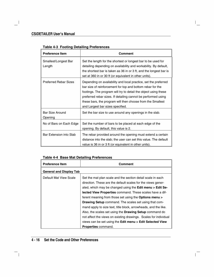
CSiDETAILER User’s Manual
4 - 16 Set the Code and Other Preferences
Table 4-3 Footing Detailing Preferences
Preference Item Comment
Smallest/Longest Bar
Length
Set the length for the shortest or longest bar to be used for
detailing depending on availability and workability. By default,
the shortest bar is taken as 36 in or 3 ft, and the longest bar is
set at 360 in or 30 ft (or equivalent in other units).
Preferred Rebar Sizes Depending on availability and local practice, set the preferred
bar size of reinforcement for top and bottom rebar for the
footings. The program will try to detail the object using these
preferred rebar sizes. If detailing cannot be performed using
these bars, the program will then choose from the Smallest
and Largest bar sizes specified.
Bar Size Around
Opening
Set the bar size to use around any openings in the slab.
No of Bars on Each Edge Set the number of bars to be placed at each edge of the
opening. By default, this value is 2.
Bar Extension into Slab The rebar provided around the opening must extend a certain
distance into the slab; the user can set this value. The default
value is 36 in or 3 ft (or equivalent in other units).
Table 4-4 Base Mat Detailing Preferences
Preference Item Comment
General and Display Tab
Default Mat View Scale Set the mat plan scale and the section detail scale in each
direction. These are the default scales for the views gener-
ated, which may be changed using the Edit menu > Edit Se-
lected View Properties command. These scales have a dif-
ferent meaning from those set using the Options menu >
Drawing Setup command. The scales set using that com-
mand apply to size text, title block, arrowheads, and the like.
Also, the scales set using the Drawing Setup command do
not affect the views on existing drawings. Scales for individual
views can be set using the Edit menu > Edit Selected View
Properties command.

Chapter 4 Set Up the Detailing Model
Set the Code and Other Preferences 4 - 17
Table 4-4 Base Mat Detailing Preferences
Preference Item Comment
Default Sections Set the number of default sections in each direction. This
number is used when detailing is run for the first time. The
number and location of the marked sections can be changed
using the Section Line Editor (see Chapter 5).
Detailing Mode The Detailing Mode is activated when the Curtail bars using
the computed Area of Steel option is selected. The Detailing
All Bars option will perform detailing in the usual way, detailing
all the bars on the plan. The Detail Bars Above Typical option
will detail only the bars that the user has specified above the
typical detailing. Preference for selection of such bars can be
specified using the options listed on the form.
Rebar Calls Select the amount of information to be displayed for each re-
bar call. The Sample Rebar Call display will be updated with
every selection.
Rebar Selection
Smallest Bar Size The minimum size of reinforcing bar used for mat detailing.
Any bar can be set as the minimum size for detailing, de-
pending on the availability of bars.
Largest Bar Size The largest size of reinforcing bar used for mat detailing. The
size should be larger than or equal to the smallest bar size.
Minimum/Maximum
Number of Bars
Restrict the number of bars used for reinforcing in the model
by specifying the minimum/maximum number of bars. The
default value for the minimum number is 2 and the maximum
number is 100.
Maximum Mixed Bar
Sizes
To achieve optimal detailing, the detailing model uses more
than one rebar size. Limit the number of mixed bar sizes to
save logistic, cutting and placing costs. By default, this value is
set as 2 (i.e., two different sizes of bars are used for detailing).

CSiDETAILER User’s Manual
4 - 18 Set the Code and Other Preferences
Table 4-4 Base Mat Detailing Preferences
Preference Item Comment
Maximum Excess Area Usually during detailing, some excess area of reinforcing is
used. The detailing model can limit the excess area to a user-
defined value by choosing appropriate bar sizes within the
specified bar size and spacing limitations. The value is ex-
pressed as a percentage of required area, and by default, is
set at 20%. Set this property to make the design more eco-
nomical.
Minimum/Maximum
Spacing of Bars
The minimum and maximum bar spacing limitations are de-
fined in structural design codes. The detailing model uses de-
fault minimum and maximum bar spacing of 4 in and 18 in,
respectively (or equivalent in other units).
Smallest/Longest Bar
Length
Depending on the availability, workability, and requirements of
the code, set the length for the shortest or longest bar to be
used for detailing. By default, the length of shortest bar is
taken as 36 in or 3 ft and the longest bar is set at 360 in or 30
ft (or equivalent in other units).
Bar Size Around
Opening
Set the bar size to use around any openings in the slab.
No of Bars on Each Edge Set the number of bars to be placed at each edge of the
opening. By default, this value is 2.
Bar Extension into Slab The rebar provided around the opening must extend a certain
distance into the slab; the user can set this value. The default
value is 36 in or 3 ft (or equivalent in other units).
Preferred Bar Size Depending on availability and local practice, set preferred bar
size for top and bottom reinforcement. Any rebar number can
be selected from the drop-down list. The program will try to
detail the object using these preferred rebar sizes. If detailing
cannot be performed using these bars, the program will then
choose from the Smallest and Largest bar sizes specified.
Enforce Minimum Ast
Limits
If the Enforce the User Minimum Reinforcement option is se-
lected, CSiDETAILER checks and enforces these limits while
selecting rebar for detailing. These preferences can be set
independently for top and bottom bars. By default, the mini-
Chapter 4 Set Up the Detailing Model
Set the Drawing Layout 4 - 19
Table 4-4 Base Mat Detailing Preferences
Preference Item Comment
mum area for top and bottom reinforcement is set to 0.18% of
the concrete area.
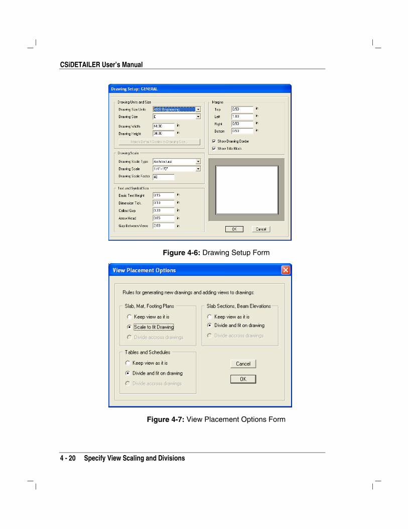
Set the Drawing LayoutClick the Options menu > Drawing Setup command to open theDrawing Setup form shown in Figure 4-6. Use the form to setup drawingunits and size, drawing scale, text and symbol size and margins. Whenthe options and preferences are set before detailing is performed, thoseoptions and preferences apply to all drawings detailed. If it is necessarythat the project file contain drawings that have different sizes, scales, andsetups, the Drawing Setup form can be used to change the setup on adrawing-by-drawing basis. After options and preferences have beenspecified, CSiDETAILER retains the specified options so that if the de-tailing is rerun, each drawing will update the views in accordance withthe drawing setup and view properties.
Specify View Scaling and Divisions In some cases, views may not fit the drawing size. In those cases,CSiDETAILER can maintain the view as is, or scale and divide it to fitthe drawing. Click the Options menu > View Placement Optionscommand to access the View Placement Options form (Figure 4-7) andselect the appropriate option.
CSiDETAILER User’s Manual
4 - 20 Specify View Scaling and Divisions
Figure 4-6: Drawing Setup Form
Figure 4-7: View Placement Options Form
Chapter 4 Set Up the Detailing Model
Set Graphical Elements 4 - 21
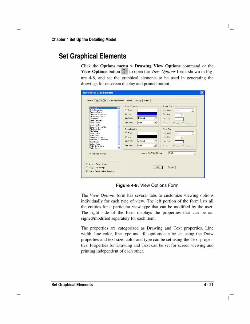
Set Graphical Elements Click the Options menu > Drawing View Options command or theView Options button to open the View Options form, shown in Fig-
ure 4-8, and set the graphical elements to be used in generating thedrawings for onscreen display and printed output.
Figure 4-8: View Options Form
The View Options form has several tabs to customize viewing optionsindividually for each type of view. The left portion of the form lists allthe entities for a particular view type that can be modified by the user.The right side of the form displays the properties that can be as-signed/modified separately for each item.
The properties are categorized as Drawing and Text properties. Linewidth, line color, line type and fill options can be set using the Drawproperties and text size, color and type can be set using the Text proper-ties. Properties for Drawing and Text can be set for screen viewing andprinting independent of each other.

CSiDETAILER User’s Manual
4 - 22 Set Graphical Elements
Layers may be assigned to objects using the Layer drop-down list, whichlists all the currently defined layers. The layers are used when the projectfile is exported to .DXF or DWG file format.
Checking the Apply to Current Drawing check box will affect the currentdrawing only; therefore, different drawings can have different viewingoptions. To use the specified drawing view options as default for all newDrawings, check the Use as Default for New Drawings check box.
Set Layers for DXF/DWG Export Layers consist of properties (line type, line thickness, line color, textsize, text color) that are used in generating DXF or DWG files. CSiDE-TAILER has default layer names, such as grid, concrete, rebar, dimlines,caption, rebarcalls, hiddenlines, centerline, and text that reflect the char-acteristics of the objects in the detailing model.
Define Layers Click the Options menu > Define View Layers command to open theLayer List form shown in Figure 4-9. Use the Add or Modify/Showbutton on that form to access the Layer Properties form shown in Figure4-10. Use the Layer Properties form to change the layer name or any ofthe properties comprising the layer.
Figure 4-9 Layer List Form Figure 4-10 LayerProperties Form
Chapter 4 Set Up the Detailing Model
Specify Symbols 4 - 23
Assign Objects to Layers The entities used to illustrate the objects in the detailing model (e.g., gridlines, north symbol, slab outline, slab dimensions and so forth) can be as-signed to layers that are used by CAD-based programs to facilitatechanges to those graphical elements. For example, if all slab-relatedproperties are assigned to the same layer, when the .DXF or DWG file isused by a CAD-based program, the color for all slab-related ob-jects/entities/elements can be changed with a single operation, or all suchelements can be made visible or invisible. Thus, assigning detailer enti-ties/objects to layers should be completed with consideration for how theCAD-based program will use the output.
Objects/entities can be assigned to named layers using the Layer forDXF/DWG Export drop-down list on the Drawing View Options form,which can be displayed using the Options menu > Drawing View Op-tions command. First select the object/entity to be assigned to a layerfrom the display area on the left portion of the Drawing View Optionsform. Then select the layer name from the Layer for DXF/DWG Exportdrop-down list.
Specify Symbols CSiDETAILER provides versatility for selecting drawing symbols forvarious drawing items. Those items include view captions, dimensionline arrows, section marks, and other symbols. Click the Options menu> Drawing Symbols command (use the Detailing menu > DrawingSymbols command in SAFE) to open the Drawing Items Symbols formshown in Figure 4-11 and set the symbols to be used consistentlythroughout the model. The drawing symbols apply to all drawings.
Note: Specify the North Symbol using the Drawing Items Symbolsform. Add the symbol to a drawing using the Drawing menu > AddNorth Symbol command.

CSiDETAILER User’s Manual
4 - 24 Specify Symbols
Figure 4-11: Drawing Item Symbols Form
The following table shows the default symbols that the program uses forvarious drawing items:
Drawing Item Default Symbol
View Caption
Dimension Line Arrow
Slab/Mat Section Mark
Beam/Footing SectionMark
North Symbol

5 - 1
Chapter 5
Generate and Add Views
To add views, set up the detailing model (Steps 1 through 4 of the Gen-eral Process in Chapter 2). The program adds many basic drawings tothe project, each drawing containing several views. Additional views canbe added to the drawings while previously added views can be edited.Additional drawings may also be added to the project.
This chapter describes how drawings can be generated and how varioustypes of views can be added to drawings. It also identifies the commandsused to add those views. Information about editing views and sectionlines and adjusting viewing properties for the individual views is also in-cluded.
Detail Views and Generate Drawings Depending on the complexity of the model, detailing views and generat-ing drawings can be time consuming after CSiDETAILER has been en-abled. The Detailing Status form displays the extent of detailing com-pleted and the object currently being detailed. After detailing has been
CISCOLCISDetailerCISCOLCISCOLCSiDETAILER™CISCOLCISCOLCISDetailerCISDetailerCISCOLCISCOLCISCOLCISCOLCSiDETAILER™

CSiDetailer User’s Manual
5 - 2 Types of Views and Commands to Add Views
completed, CSiDETAILER automatically generates basic drawings forthe model. The Drawing Explorer displays the drawing name along withthe list of entities contained on each drawing. As changes are made to thegenerated drawings, use the Drawing > Update and Refresh AllDrawings menu command to refresh drawings. This will also rerun de-tailing if needed. Views can be added to any of the generated drawings orblank drawings can be included in the model and views can be added tothose drawings. The following section describes how to add views todrawings.
Types of Views and Commands to Add Views Table 5-1 lists the types of view generated during detailing and thecommands used to add the relevant type of view to drawings after de-tailing.
Table 5-1 Types of Views That Can Be Added to Drawings
View Type Description/Command
Slab Plan A slab plan is a view that shows the X-Y plane, including thegeometry of the user developed model and the reinforcementdetailing calculated by the program. Add a slab plan view to adrawing using the Drawing menu > Add Slab Views > SlabReinforcement Plan (indicative bars/all bars) command or
the Add Slab Views button .
Slab Sections By default, the program cuts four slab sections; two in eachdirection. However, more sections per direction can be addedusing the General and Display tab on the Slab Detailing Pref-erence form (see the Options menu > Main Detailing Pref-erences command). Add a slab section view to a drawing us-ing the Drawing menu > Add Slab Views > Slab Sections
command or the Add Slab Views button . Additionalsections may be defined using the Edit menu > Edit SlabSection Lines command.
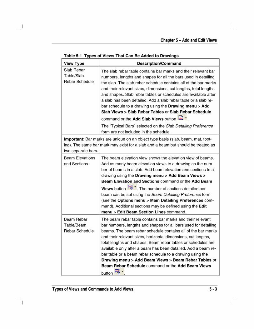
Chapter 5 – Add and Edit Views
Types of Views and Commands to Add Views 5 - 3
Table 5-1 Types of Views That Can Be Added to Drawings
View Type Description/Command
Slab RebarTable/SlabRebar Schedule
The slab rebar table contains bar marks and their relevant barnumbers, lengths and shapes for all the bars used in detailingthe slab. The slab rebar schedule contains all of the bar marksand their relevant sizes, dimensions, cut lengths, total lengthsand shapes. Slab rebar tables or schedules are available aftera slab has been detailed. Add a slab rebar table or a slab re-bar schedule to a drawing using the Drawing menu > AddSlab Views > Slab Rebar Tables or Slab Rebar Schedule
command or the Add Slab Views button .
The “Typical Bars” selected on the Slab Detailing Preferenceform are not included in the schedule.
Important: Bar marks are unique on an object type basis (slab, beam, mat, foot-ing). The same bar mark may exist for a slab and a beam but should be treated astwo separate bars.
Beam Elevationsand Sections
The beam elevation view shows the elevation view of beams.Add as many beam elevation views to a drawing as the num-ber of beams in a slab. Add beam elevation and sections to adrawing using the Drawing menu > Add Beam Views >Beam Elevation and Sections command or the Add Beam
Views button . The number of sections detailed perbeam can be set using the Beam Detailing Preference form(see the Options menu > Main Detailing Preferences com-mand). Additional sections may be defined using the Editmenu > Edit Beam Section Lines command.
Beam RebarTable/BeamRebar Schedule
The beam rebar table contains bar marks and their relevantbar numbers, lengths and shapes for all bars used for detailingbeams. The beam rebar schedule contains all of the bar marksand their relevant sizes, horizontal dimensions, cut lengths,total lengths and shapes. Beam rebar tables or schedules areavailable only after a beam has been detailed. Add a beam re-bar table or a beam rebar schedule to a drawing using theDrawing menu > Add Beam Views > Beam Rebar Tables orBeam Rebar Schedule command or the Add Beam Views
button .

CSiDetailer User’s Manual
5 - 4 Types of Views and Commands to Add Views
Table 5-1 Types of Views That Can Be Added to Drawings
View Type Description/Command
Mat Plan A mat plan shows the X-Y plane, including the geometry of theuser developed model and the reinforcement detailing calcu-lated by the program. Add a mat plan view to a drawing usingthe Drawing menu > Add Mat Views > Mat ReinforcementPlan (indicative bars/all bars) command, or the Add Mat
Views button .
Mat Sections By default, the program cuts four mat sections, two in each di-rection. Add more sections per direction using the General andDisplay tab on the Mat Detailing Preference form (see theOptions menu > Main Detailing Preferences command).Add a mat section view to a drawing using the Drawing menu> Add Mat Views > Mat Sections command or the Add Mat
Views button . Additional sections may be defined usingthe Edit menu > Edit Mat Section Lines command.
Mat RebarTable/Mat RebarSchedule
The mat rebar table contains bar marks and their relevant barnumbers, lengths and shapes for all the bars used for detailingthe mat. The mat rebar schedule contains all of the bar marksand their relevant sizes, dimensions, cut lengths, total lengthsand shapes. Mat rebar tables or schedules are available onlyafter a mat has been detailed. Add a mat rebar table or a matrebar schedule to a drawing using the Drawing menu > AddMat Views > Mat Rebar Tables or Mat Rebar Schedule
command or the Add Mat Views button .
Footing Plan Add a footing plan view to a drawing using the Drawing menu> Add Footing Views > Footing Plans and Sections com-
mand or the Add Footing Views button .
Footing Sections By default, the program cuts two footing sections, one in eachdirection. Add more sections per direction using the Generaland Display tab on the Footing Detailing Preference form (seethe Options menu > Main Detailing Preferences command).Add a footing section view to a drawing using the Drawingmenu > Add Footing Views > Footing Plans and Sections
command or the Add Footing Views button .

Chapter 5 – Add and Edit Views
Edit Section Lines 5 - 5
Table 5-1 Types of Views That Can Be Added to Drawings
View Type Description/Command
Footing RebarTable/FootingRebar Schedule
The footing rebar table contains bar marks and their relevantbar numbers, lengths and shapes for all the bars used for de-tailing the footing. The footing rebar schedule contains all ofthe bar marks and their relevant sizes, dimensions, cutlengths, total lengths and shapes. Footing rebar tables orschedules are available only after a footing has been detailed.Add a footing rebar table or a footing rebar schedule to a draw-ing using the Drawing menu > Add Footing Views > FootingRebar Table or Footing Rebar Schedule command or the
Add Footing Views button .
Edit Section Lines Add, delete, move or change the length of section lines for slabs, matsand beams using the Section Line Editor. Section lines can be movedgraphically or numerically. The Editor also offers conventional zoomingoptions to make editing section lines easier.
Edit Slab or Mat Section Lines Section lines can be added to or deleted from slab or mat plan views , aswell as moved graphically or numerically using the Section Line Editorshown in Figure 5-1. The length of a section line also can be modified.
Add a new section line as follows:
1. Click the Edit menu > Edit Slab Section Lines/Mat Section
Lines command or the Edit Slab Section Lines button or
Edit Mat Section Line button to open the Section Line Edi-tor shown in Figure 5-1.
2. Click the Cut Section Along X button or the Cut SectionAlong Y button to add a new section line in the respective
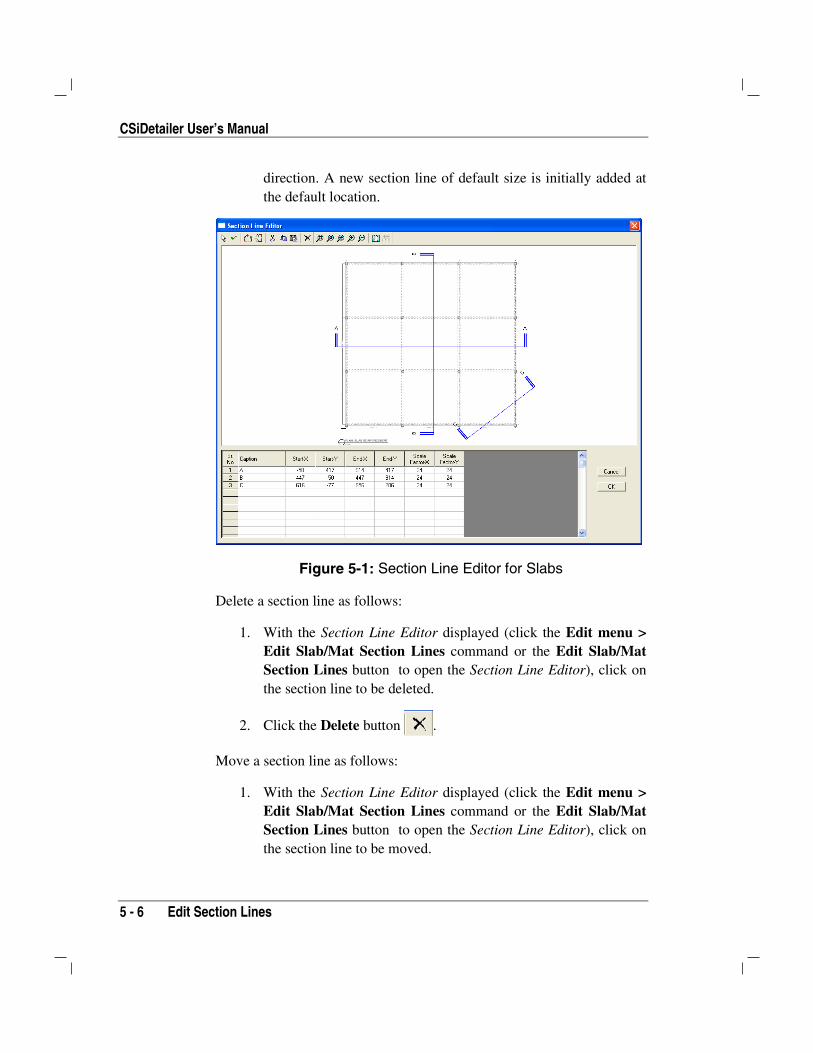
CSiDetailer User’s Manual
5 - 6 Edit Section Lines
direction. A new section line of default size is initially added atthe default location.
Figure 5-1: Section Line Editor for Slabs
Delete a section line as follows:
1. With the Section Line Editor displayed (click the Edit menu >Edit Slab/Mat Section Lines command or the Edit Slab/MatSection Lines button to open the Section Line Editor), click onthe section line to be deleted.
2. Click the Delete button .
Move a section line as follows:
1. With the Section Line Editor displayed (click the Edit menu >Edit Slab/Mat Section Lines command or the Edit Slab/MatSection Lines button to open the Section Line Editor), click onthe section line to be moved.
Chapter 5 – Add and Edit Views
Edit Section Lines 5 - 7
2. Hold down the mouse button and drag the section line to the newlocation. Alternatively, click on the appropriate cell in thespreadsheet in the lower left corner of the form and type in a re-vised location for the Start and End X and Y coordinates that de-fine the section line.
Change the length of a section line as follows:
1. With the Section Line Editor displayed (click the Edit menu >Edit Slab/Mat Section Lines command or the Edit Slab/MatSection Lines button to open the Section Line Editor), click onthe section line to be changed.
2. When the section line is selected, dimensioning handles appearat both ends. Drag any one of the dimensioning handles tochange the length of the section line. Alternatively, click on theappropriate cell in the spreadsheet in the lower left corner of theform and type in a revised location for the Start and End X and Ycoordinates that define the section line.
When a section is added, the section line is shown on the plan view ofthe slab/mat but the new section is not added to the project. Click theDrawing menu > Add Slab/Mat View > Slab/Mat Section commandto add the section; select the section from the list on the Add Object Viewto Drawing form. When a section is modified, the previous section is up-dated in accordance with the modification at all locations in the projectfile. Deleting a section line will delete the section mark on the plan view,while removing the section detail from all drawings in the project file.
Edit Beam Section Lines Section lines can be added to or deleted from beam elevation views, aswell as moved graphically or numerically using the Section Line Editorshown in Figure 5-2. The length of a section line also can be modified.

CSiDetailer User’s Manual
5 - 8 Edit Section Lines
Figure 5-2: Section Line Editor for Beams
Add a new section line as follows:
1. Click the Edit menu > Edit Beam Section Lines command or
the Edit Beam Section Lines button to open the Section
Line Editor.
2. Select the beam name from the Beam drop-down list to displaythe beam in the drawing area.
3. Click the Cut Section button to add a new section line. Anew section line of default size is initially added at the defaultlocation.
Delete a section line as follows (see IMPORTANT NOTE):
1. With the Section Line Editor displayed (click the Edit menu >Edit Beam Section Lines command or the Edit Beam Section

Chapter 5 – Add and Edit Views
Check and Edit Reinforcement 5 - 9
Lines button to open the Section Line Editor), select the
beam from the Beam drop-down list to display the beam in thedrawing area.
2. Click on the section line to be deleted.
3. Click the Delete button .
Move a section line as follows:
1. With the Section Line Editor displayed (click the Edit menu >Edit Beam Section Lines command or the Edit Beam Section
Lines button to open the Section Line Editor), select the
beam from the Beam drop-down list to display the beam in thedrawing area.
2. Click on the section line to be moved.
3. Hold down the mouse button and drag the section line to the newlocation. Alternatively, click on the appropriate cell in thespreadsheet in the lower left corner of the form and type in a re-vised location for the distance that defines the section line.
IMPORTANT NOTE: As soon as another beam is selected, CSiDE-TAILER saves the modifications made on the previous beam.
Check and Edit Reinforcement Use the Edit menu > Check and Edit Reinforcement command tocheck and edit the detailing output generated by CSiDETAILER. Usethe command to change the rebar sizes, number of bars, and the rebar ex-tents for reinforcement in slab/mat/footing plans and edit the rebar sizeand extent for reinforcements in beam elevations.
The Check and Edit Reinforcement form shown in Figure 5-3 displayswhen the Edit menu > Check and Edit Reinforcement command isclicked.

CSiDetailer User’s Manual
5 - 10 Check and Edit Reinforcement
Figure 5-3 Check and Edit Reinforcement form
When the form is activated, it displays the slab plan by default, showinggraphically the rebar details for Strip1. The right side of the form dis-plays the tabulated reinforcement details for top steel, bottom steel andstirrups. In addition, properties of the selected rebars are shown under theSelected Rebar Call heading. The various parts of the form are describedin the subsections that follow.
Toolbar The following toolbar is available on the form
Click to refresh and update the currently displayed de-tailing view.
Select Object Type to be displayed on the display area.All object types available in the detailing model are listedhere and may include beams, slabs, footings and mats.
Select the view of the object type selected using the Ob-ject Type drop-down list. This displays the strip fromslabs, mats and footings and beam number for beams.
Saves the currently displayed tables in a text file.
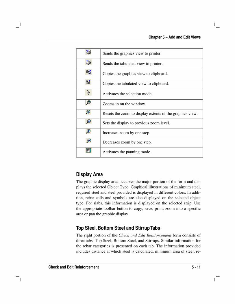
Chapter 5 – Add and Edit Views
Check and Edit Reinforcement 5 - 11
Sends the graphics view to printer.
Sends the tabulated view to printer.
Copies the graphics view to clipboard.
Copies the tabulated view to clipboard.
Activates the selection mode.
Zooms in on the window.
Resets the zoom to display extents of the graphics view.
Sets the display to previous zoom level.
Increases zoom by one step.
Decreases zoom by one step.
Activates the panning mode.
Display Area The graphic display area occupies the major portion of the form and dis-plays the selected Object Type. Graphical illustrations of minimum steel,required steel and steel provided is displayed in different colors. In addi-tion, rebar calls and symbols are also displayed on the selected objecttype. For slabs, this information is displayed on the selected strip. Usethe appropriate toolbar button to copy, save, print, zoom into a specificarea or pan the graphic display.
Top Steel, Bottom Steel and Stirrup Tabs The right portion of the Check and Edit Reinforcement form consists ofthree tabs: Top Steel, Bottom Steel, and Stirrups. Similar information forthe rebar categories is presented on each tab. The information providedincludes distance at which steel is calculated, minimum area of steel, re-

CSiDetailer User’s Manual
5 - 12 Check and Edit Reinforcement
quired area of steel and the area of steel provided. In addition, the per-centages of area of steel required to be provided and minimum providedare also reported. All cells are non-editable.
When a rebar call is selected for editing on the graphical view, the cellsin the Selected Rebar Call column can be edited.
Edit Slab/Mat/Footing Reinforcement
Reinforcement can be added graphically to slabs, mats, and footings us-ing the Check and Edit Reinforcement form as follows:
1. Click the Edit menu > Check and Edit Reinforcement com-mand to display the Check and Edit Reinforcement form.
2. Select the Slab Strip option from the Object Type drop-down list.
3. Select the strip to be edited from the Strip drop-down list. TheGraphical Display area will show the reinforcement for that strip.Choose to view strips in the x direction, the y direction, or allstrips simultaneously.
4. Zoom in to view the strip.
5. Click the Selection Mode button on the toolbar.
6. Click on the rebar call to be edited. The editable properties of theselected call will be displayed in the Selected Rebar Call columnof the spreadsheet area.
7. When all editing is complete, click the Refresh View button toupdate the graphics and tabulated output.
Note: The results generated by SAFE are considered as required area forsteel, while the minimum reinforcing bar limits are those specified usingthe {Object} Detailing Preference form, which can be accessed using theOptions menu > Main Detailing Preferences command.
The information that can be edited includes the Reinforcement List (re-bar size and number), bar start and end distances, rebar call offset (Dx)and rebar symbol offset (Dy). Figures 5-4 and 5-5 illustrates the various

Chapter 5 – Add and Edit Views
Check and Edit Reinforcement 5 - 13
parameters that may be edited when a slab strip rebar call has been se-lected.
X
Y
6-#5
Bar 1: Start, X1 Dx
Bar 1Bar 2
Bar 2: Start, X3
Bar 2: End, X4
Bar 1: End, X2
Dy
X Strip
Figure 5-4: The various parameters that can beedited on the slab X-strip
Note: A rebar call can be changed as many times as needed.
Edit Beam Reinforcement Edit beam reinforcement as follows:
1. Click the Edit menu > Check and Edit Reinforcement com-mand to display the Check and Edit Reinforcement form.
2. Select the Beams option from the Object Type drop-down list.
3. Select the beam to be edited from the Beam dropdown list. TheGraphical Display area will show the reinforcement for thatbeam.
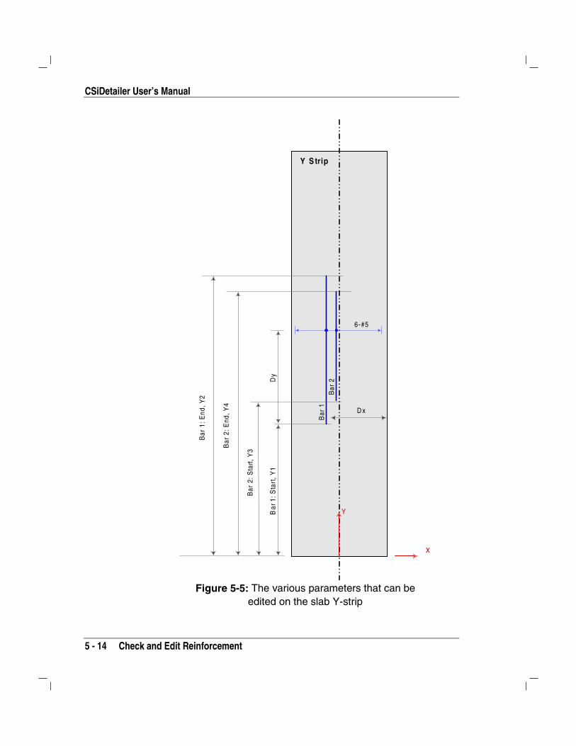
CSiDetailer User’s Manual
5 - 14 Check and Edit Reinforcement
X
Y
6-#5
Bar
1: S
tart
, Y1
D x
Bar
1B
ar 2
Bar
2: S
tart,
Y3
Bar
2: E
nd, Y
4
Bar
1: E
nd, Y
2
Dy
Y S trip
Figure 5-5: The various parameters that can beedited on the slab Y-strip

Chapter 5 – Add and Edit Views
Check and Edit Reinforcement 5 - 15
4. Zoom in on the beam view.
5. Click the Selection Mode button on the toolbar.
6. Click on the rebar call to be edited. The editable properties of theselected call will display in the Selected Rebar Call column ofthe spreadsheet area. Click in the appropriate cell to edit the re-bar size and extent.
7. When all the editing is complete, click the Refresh View buttonto update the graphics and tabulated output.
The information that can be edited includes the rebar size, rebar start dis-tance and end distance. Figure 5-6 illustrates the various parameters thatmay be edited when a beam rebar call has been selected.
Grid
Lin
e
Grid
Lin
e#5
#7
#5
#7
#7#8
#7
#5#5
Bar SizeBar Start, X1
Bar End, X2
Selected Bar
Figure 5-6: The various parameters that can beedited on the beam

6 - 1
Chapter 6
Manage Views and Drawings
CSiDETAILER provides tools for adding drawings to a project file andarranging the available views on the drawings. Views can be selected andcut, copied, and pasted on the same drawing and from drawing to draw-ing within the same project file. Views also can be stacked and aligned,and numerically located relative to the lower left-hand corner of thedrawing. This chapter briefly describes how to add drawings to a projectfile, add views to a drawing or delete them, access the text of a viewcaption, and as necessary, arrange the views on a drawing.
Add Drawings to the Project File When the detailing and drawing generation process is complete, CSiDE-TAILER automatically adds to the project file all views and associateddrawings that are available based on the design model input.
More control over creation of the drawings is possible using a combina-tion of commands on the Edit and Drawing menus.
CISCOLCISDetailerCISCOLCISCOLCSiDETAILER™CISCOLCISCOLCISDetailerCISDetailerCISCOLCISCOLCISCOLCISCOLCSiDETAILER™
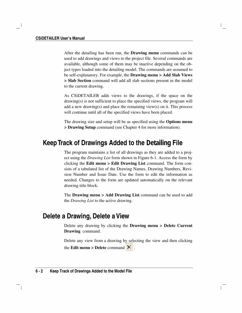
CSiDETAILER User’s Manual
6 - 2 Keep Track of Drawings Added to the Model File
After the detailing has been run, the Drawing menu commands can beused to add drawings and views to the project file. Several commands areavailable, although some of them may be inactive depending on the ob-ject types loaded into the detailing model. The commands are assumed tobe self-explanatory. For example, the Drawing menu > Add Slab Views> Slab Section command will add all slab sections present in the modelto the current drawing.
As CSiDETAILER adds views to the drawings, if the space on thedrawing(s) is not sufficient to place the specified views, the program willadd a new drawing(s) and place the remaining view(s) on it. This processwill continue until all of the specified views have been placed.
The drawing size and setup will be as specified using the Options menu> Drawing Setup command (see Chapter 4 for more information).
Keep Track of Drawings Added to the Detailing FileThe program maintains a list of all drawings as they are added to a proj-ect using the Drawing List form shown in Figure 6-1. Access the form byclicking the Edit menu > Edit Drawing List command. The form con-sists of a tabulated list of the Drawing Names, Drawing Numbers, Revi-sion Number and Issue Date. Use the form to edit the information asneeded. Changes to the form are updated automatically on the relevantdrawing title block.
The Drawing menu > Add Drawing List command can be used to addthe Drawing List to the active drawing.
Delete a Drawing, Delete a View Delete any drawing by clicking the Drawing menu > Delete CurrentDrawing command.
Delete any view from a drawing by selecting the view and then clicking
the Edit menu > Delete command .

Chapter 6 – Edit Drawings
Select a View 6 - 3
Figure 6-1: Drawing List Form
Select a View Views must be selected before any operation can be performed on themor with them.
Select a single view by clicking on it.
Select multiple views by:
drawing a window around them
holding the Shift key while clicking the views one by one
Deselect selected views by clicking any blank area on a drawing or usingthe View menu > Clear Selection command.
Select all views on a drawing using the View menu > Select All com-mand.

CSiDETAILER User’s Manual
6 - 4 Arrange Views on the Drawings
Arrange Views on the Drawings
Cut, Copy, Paste Views Views on any drawing can be cut, copied, and pasted on the same draw-ing or from drawing to drawing within the same project file.
1. Select the view to be cut or copied and pasted.
2. Click the cut or copy command in the Edit menu to temporarilystore the view on the system Clipboard.
3. Click the paste command in the Edit menu at the new location toplace the cut or copied view.
TIP: Place views on new or existing drawings by using the mouse todrag and drop them from the Drawing Explorer to the desired location.
Align Views Views added to a drawing can be aligned along their left and right edges,along their tops and bottoms, and along a center or middle line. To alignviews, select the views to be aligned and click the Drawing menu >
Align Selected Views command or the Align Views button andone of the subcommands listed in Table 6-1.
Table 6-1 Align View Commands
Command Action
Align Left The X-coordinates of the bottom-left corners of all theselected views are set equal to that of the left-mostview. If the views were selected by drawing a windowaround them, the X-coordinates of the bottom-left cor-ners of all the selected views are set equal to that ofthe left-most view.
Align Right The X-coordinates of the bottom-right corners of all theselected views are set equal to that of the left-mostview. If the views were selected by drawing a windowaround them, the X-coordinates of the bottom-right cor-ners of all the selected views are set equal to that ofthe right-most view.

Chapter 6 – Edit Drawings
Arrange Views on the Drawings 6 - 5
Table 6-1 Align View Commands
Command Action
Align Top The Y-coordinates of the top-left corners of all the se-lected views are set equal to that of the left-most view.If the views were selected by drawing a window aroundthem, the Y-coordinates of the top-left corners of all theselected views are set equal to that of the top-mostview.
Align Bottom The Y-coordinates of the bottom-left corners of all theselected views are set equal to that of the left-mostview. If the views were selected by drawing a windowaround them, the Y-coordinates of the bottom-left cor-ners of all the selected views are set equal to that ofthe lowest view.
Align Center The centroid of each selected view is moved horizon-tally such that it is set equal to the geometric center ofall of the selected views.
Align Middle The centroid of each selected view is moved verticallysuch that it is set equal to the geometric center of all ofthe selected views.
Stack Views Views can be stacked horizontally or vertically. To stack views, selectthe views to be stacked and click the Drawing menu > Stack SelectedViews command or the Stack Views button and then select one ofthe subcommands listed in Table 6-2.
Table 6-2 Stack View Commands
Command Action
Stack ViewsHorizontally
Selected views are moved horizontally such that theleft edge of the second highest order view alignswith the right edge of the highest order view, the leftedge of the third highest order view aligns with theright edge of the second highest order view, and soon for all selected views. The view placed in the up-permost left position has the highest order, with theorder decreasing across and down the sheet.
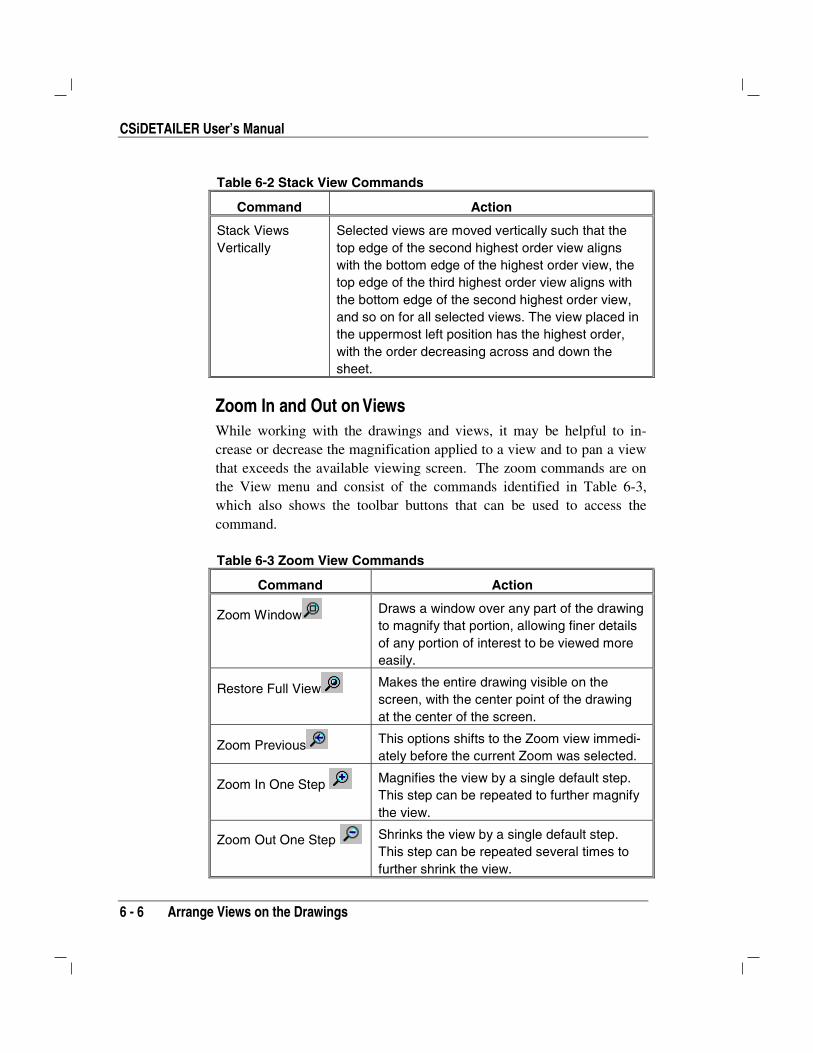
CSiDETAILER User’s Manual
6 - 6 Arrange Views on the Drawings
Table 6-2 Stack View Commands
Command Action
Stack ViewsVertically
Selected views are moved vertically such that thetop edge of the second highest order view alignswith the bottom edge of the highest order view, thetop edge of the third highest order view aligns withthe bottom edge of the second highest order view,and so on for all selected views. The view placed inthe uppermost left position has the highest order,with the order decreasing across and down thesheet.
Zoom In and Out on Views While working with the drawings and views, it may be helpful to in-crease or decrease the magnification applied to a view and to pan a viewthat exceeds the available viewing screen. The zoom commands are onthe View menu and consist of the commands identified in Table 6-3,which also shows the toolbar buttons that can be used to access thecommand.
Table 6-3 Zoom View Commands
Command Action
Zoom Window Draws a window over any part of the drawingto magnify that portion, allowing finer detailsof any portion of interest to be viewed moreeasily.
Restore Full View Makes the entire drawing visible on thescreen, with the center point of the drawingat the center of the screen.
Zoom Previous This options shifts to the Zoom view immedi-ately before the current Zoom was selected.
Zoom In One Step Magnifies the view by a single default step.This step can be repeated to further magnifythe view.
Zoom Out One Step Shrinks the view by a single default step.This step can be repeated several times tofurther shrink the view.

Chapter 6 – Edit Drawings
Modify View Captions Locations 6 - 7
Table 6-3 Zoom View Commands
Command Action
Pan Changes the mouse pointer to a four-sidedarrow. Click and drag the image to the left,right, top or bottom to adjust the view as de-sired.
Modify View Captions Locations Captions can be added to individual views and the placement of theviews can be adjusted using the Selected View Properties form shown inFigure 6-2.
Figure 6-2: Selected View Properties Form
To access the form, select a view or views by clicking on it/them or bywindowing over it/them. Then, right click on the selected view(s) orclick the Edit menu > Edit Selected View Properties command to openthe Selected View Properties form.

CSiDETAILER User’s Manual
6 - 8 Modify View Captions Locations
If multiple views with different properties are selected, some of the editboxes on the form will be empty, such as the Caption edit box and theLocation X and Location Y, depending on the location of the forms rela-tive to one another.
Table 6-4 identifies the parameters on the Selected View Properties formand briefly explains the parameter’s function.
Table 6-4 Parameters on the Selected View Properties Form
Parameter Description
Caption. By default a Caption is assigned to each view.Type in a different Caption for each View, if de-sired.
Parent Object. Non-editable property that shows the link betweenthe current object or view and the object from whichit has been derived. For example, a section of abeam will show the name of the beam as its parentobject.
View Type. Non-editable property that shows the relevant viewtype number for the selected View.
Location X. Type a value to locate the X coordinate of the se-lected view. The origin is set at the bottom left cor-ner of the drawing, with positive X towards theright. Any value typed in as the Location X is in re-lation to the X-coordinate of the bottom left cornerof the selected view in the specified drawing units.For example, a value of 5 means that the selectedview is to be located 5 drawing units to the right ofthe bottom left corner of the drawing.
Location Y. Type a value to locate the Y coordinate of the se-lected view. The origin is set at the bottom left cor-ner of the Drawing with positive Y upwards. Anyvalue typed in as the Location Y is in relation to theY-coordinate of bottom left corner of the selectedview in the specified drawing units. For example, avalue of 5 for Location Y means that the selectedview is to be placed 5 drawing units above thebottom left corner of the drawing.
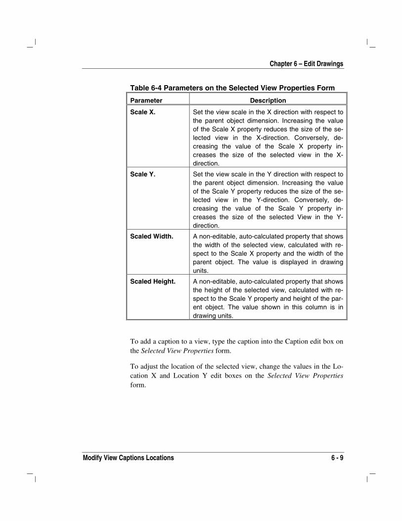
Chapter 6 – Edit Drawings
Modify View Captions Locations 6 - 9
Table 6-4 Parameters on the Selected View Properties Form
Parameter Description
Scale X. Set the view scale in the X direction with respect tothe parent object dimension. Increasing the valueof the Scale X property reduces the size of the se-lected view in the X-direction. Conversely, de-creasing the value of the Scale X property in-creases the size of the selected view in the X-direction.
Scale Y. Set the view scale in the Y direction with respect tothe parent object dimension. Increasing the valueof the Scale Y property reduces the size of the se-lected view in the Y-direction. Conversely, de-creasing the value of the Scale Y property in-creases the size of the selected View in the Y-direction.
Scaled Width. A non-editable, auto-calculated property that showsthe width of the selected view, calculated with re-spect to the Scale X property and the width of theparent object. The value is displayed in drawingunits.
Scaled Height. A non-editable, auto-calculated property that showsthe height of the selected view, calculated with re-spect to the Scale Y property and height of the par-ent object. The value shown in this column is indrawing units.
To add a caption to a view, type the caption into the Caption edit box onthe Selected View Properties form.
To adjust the location of the selected view, change the values in the Lo-cation X and Location Y edit boxes on the Selected View Propertiesform.

CSiDETAILER User’s Manual
6 - 10 Update Drawing References
Update Drawing References Information on a drawing may edited in various ways, including usingthe Edit menu > Edit Drawing Title command, the Edit menu > EditDrawing List command, the Edit menu > Edit Selected View Proper-ties command and the File menu > Project Information command. Usethe Drawing menu > Update Drawing Reference command to keep thereferences on all drawings within a project compatible and up to date.
Figure 6-3 shows the various forms that affect the updating of the TitleBlock or are updated when the Title Block is edited.
Note: Some changes made may not be automatically updated on all lo-cations. The user should execute the Drawing menu > Update DrawingReference command to ensure that all referencing is up to date.
LOGORevisionand Date
Drawing Title
Project Title
Job Title
Company
Drwg No
Date
Designerand
Checker
Drawing List Form
Drawing List
Drawing Explorer
Project InformationForm
Figure 6-3: Information Referencing and Updating System in CSiDETAILER

7 - 1
Chapter 7
Tables and General Notes
Rebar tables and rebar schedules for all detailed objects can be viewed,added to or deleted from drawings, moved, and resized. Similar to views,after a table has been added to a drawing, the Select View Propertiesform can be used to edit the table’s display properties. Bills of Quantities(BOQs) can also be generated. This chapter identifies the commands toreview and add or delete tables and to move and resize selected tablesadded to drawings and to generate BOQs.
The tables than can be generated, viewed and printed by CSiDETAILERinclude the following:
Rebar tables for slabs, beams, mats, and footing (four tabletypes). Rebar tables contain bar marks, bar numbers, lengths andshapes (text description of shapes) of all bars used in the detail-ing objects.
Rebar schedules for slabs, beams mats and footings (four tabletypes). Rebar schedules contain bar marks, bar sizes, horizontaldimensions, cut lengths, total lengths and shapes (graphical viewof shapes) of all the bars used in the detailing objects.
CISCOLCISDetailerCISCOLCISCOLCSiDETAILER™CISCOLCISCOLCISDetailerCISDetailerCISCOLCISCOLCISCOLCISCOLCSiDETAILER™

CSiDetailer User’s Manual
7 - 2 View Tables
BOQs for slabs, beams, mats, and footings (four table types). Abill of quantities lists the material items, quantities, and units forthe detailing objects in the drawing.
The tables that may be added to the drawings after detailing include thefollowing:
Slab Rebar Table and Schedule (two tables)
Beam Rebar Table and Schedule (two tables)
Mat Rebar Table and Schedule (two tables)
Footing Rebar Table and Schedule (two tables)
The content of the tables cannot be edited. The changes made to themodel after the tables have been added to the drawing will not be incor-porated in the tables. It is, therefore, recommended that the tables begenerated after all modifications to the detailing model have been madeto ensure the accuracy of their content.
View Tables View rebar tables, schedules, and BOQs by clicking the Tables menucommand. Click the Table menu > {Object Table Type} command todisplay the specified table type in the large display area on the form. Themajority of the {Object Table Type} commands are assumed to be self-explanatory. Figure 7-1 shows the Mat Rebar Schedule form.
Add Tables Add rebar tables, schedules and BOQs to drawings using the Drawingmenu > {Object View Type} > {Object Table Type} command. Tablesmay also be added using the appropriate option under the Add {ObjectType} View toolbar buttons.
After the tables have been added to drawings, they behave similar toviews. All operations described for views in Chapter 6 can be applied tothe tables.
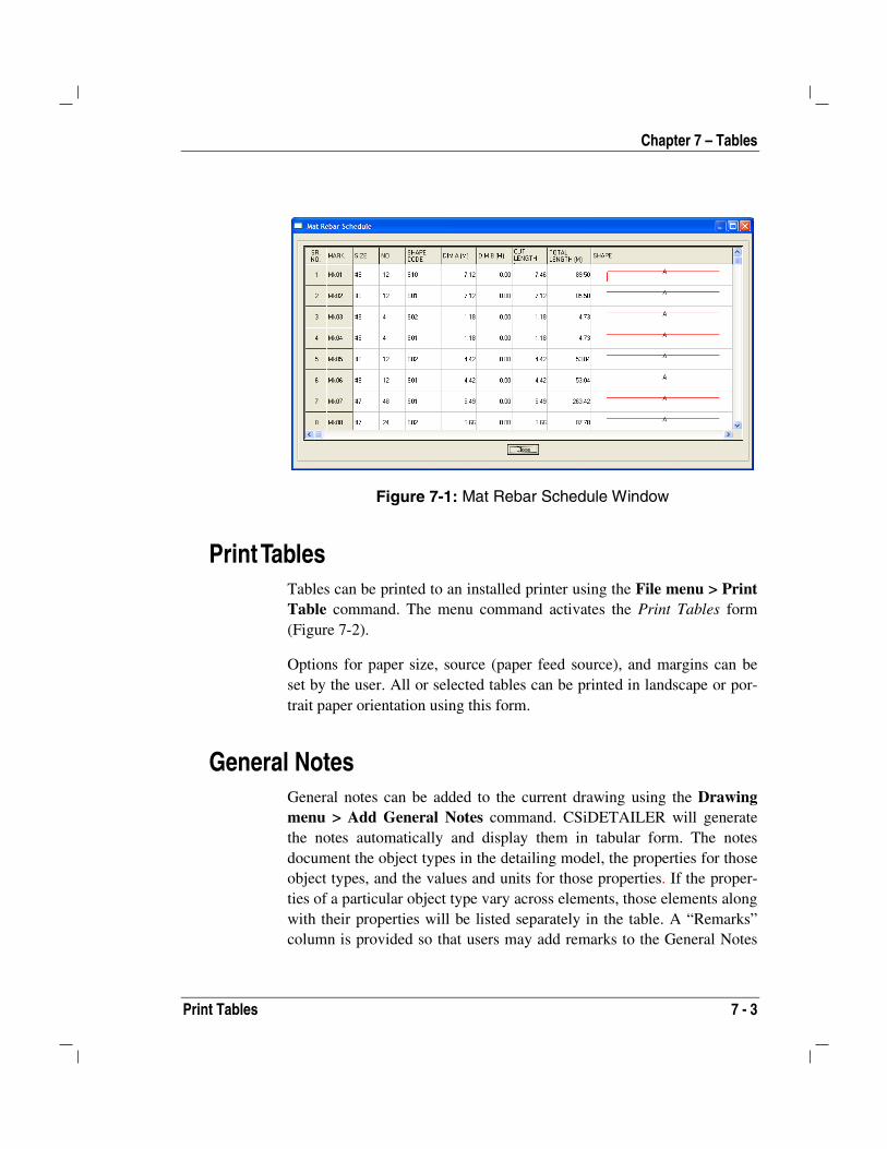
Chapter 7 – Tables
Print Tables 7 - 3
Figure 7-1: Mat Rebar Schedule Window
Print Tables Tables can be printed to an installed printer using the File menu > PrintTable command. The menu command activates the Print Tables form(Figure 7-2).
Options for paper size, source (paper feed source), and margins can beset by the user. All or selected tables can be printed in landscape or por-trait paper orientation using this form.
General Notes General notes can be added to the current drawing using the Drawingmenu > Add General Notes command. CSiDETAILER will generatethe notes automatically and display them in tabular form. The notesdocument the object types in the detailing model, the properties for thoseobject types, and the values and units for those properties. If the proper-ties of a particular object type vary across elements, those elements alongwith their properties will be listed separately in the table. A “Remarks”column is provided so that users may add remarks to the General Notes
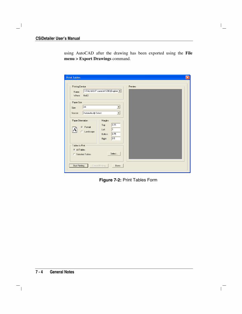
CSiDetailer User’s Manual
7 - 4 General Notes
using AutoCAD after the drawing has been exported using the Filemenu > Export Drawings command.
Figure 7-2: Print Tables Form

8 - 1
Chapter 8
Output
After drawings have been generated and edited as required, they can beprinted or exported to .DXF or .DWG file formats for further refinement,if needed, using AutoCAD or other CAD-based programs.
Note: The user is responsible for thoroughly examining the CSiDE-TAILER-generated drawings and, if necessary, refining them as needed.
Print DrawingsWhen the drawings are complete, use the File menu > Print Drawingcommand or Print Drawing button to send drawings to a specified
printer or plotter. It is strongly recommended that the drawings bechecked carefully before printing or plotting because they were createdusing data generated by an analysis and design program and additionalinformation may need to be added to the drawings. Adjust the drawinglayout settings as necessary using the Drawing Setup form, which can beaccessed using the Options menu > Drawing Setup command. Further
CISCOLCISDetailerCISCOLCISCOLCSiDETAILER™CISCOLCISCOLCISDetailerCISDetailerCISCOLCISCOLCISCOLCISCOLCSiDETAILER™

CSiDetailer User’s Manual
8 - 2 Export Drawings
information about this form is provided in the Set the Drawing Layoutsection in Chapter 4.
Export Drawings Drawings generated by CSiDETAILER can be exported to DXF andDWG file formats, which can be used by AutoCAD or other CAD-basedprograms. All drawings or only selected drawings can be exported.
Note: Before drawings are exported, it may be helpful to ensure thatlayers have been defined and objects have been assigned to those lay-ers, as described in the Set Layers for DXF/DWG Export subsection inChapter 4.
Export drawings using the File menu > Export Drawings command andthe Export Drawings form shown in Figure 8-1.
Figure 8-1: Export Drawing Form
Chapter 8 – Output
Export Drawings 8 - 3
Use the options on the form to specify the DXF or DWG file format andthe drawing(s) to be exported (the current drawing, all drawings, or se-lected drawings). Use the Target Directory edit box and button to specifythe filename and storage path for exported file.