Detailed Design Review PowerPoint Presentation
27
RIT Formula SAE Senior Design
Transcript of Detailed Design Review PowerPoint Presentation

RIT Formula SAE Senior Design
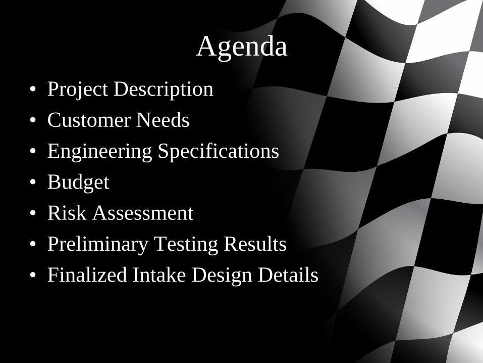
Agenda
• Project Description
• Customer Needs
• Engineering Specifications
• Budget
• Risk Assessment
• Preliminary Testing Results
• Finalized Intake Design Details
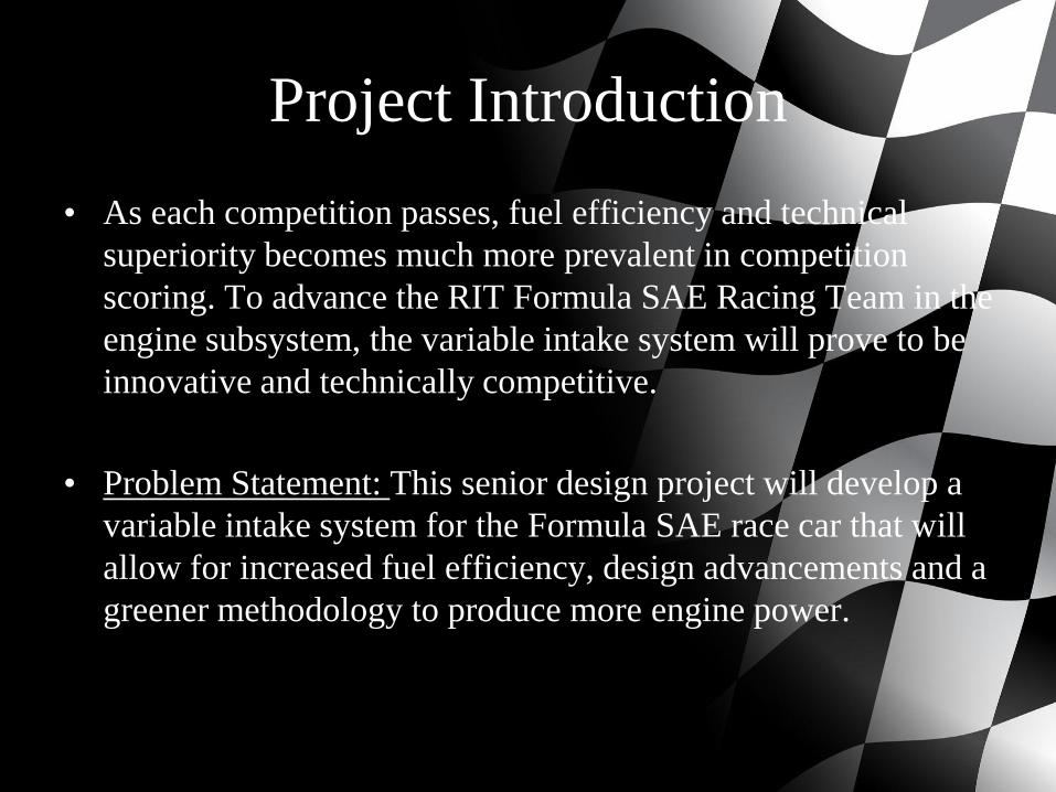
Project Introduction
• As each competition passes, fuel efficiency and technical
superiority becomes much more prevalent in competition
scoring. To advance the RIT Formula SAE Racing Team in the
engine subsystem, the variable intake system will prove to be
innovative and technically competitive.
• Problem Statement: This senior design project will develop a
variable intake system for the Formula SAE race car that will
allow for increased fuel efficiency, design advancements and a
greener methodology to produce more engine power.
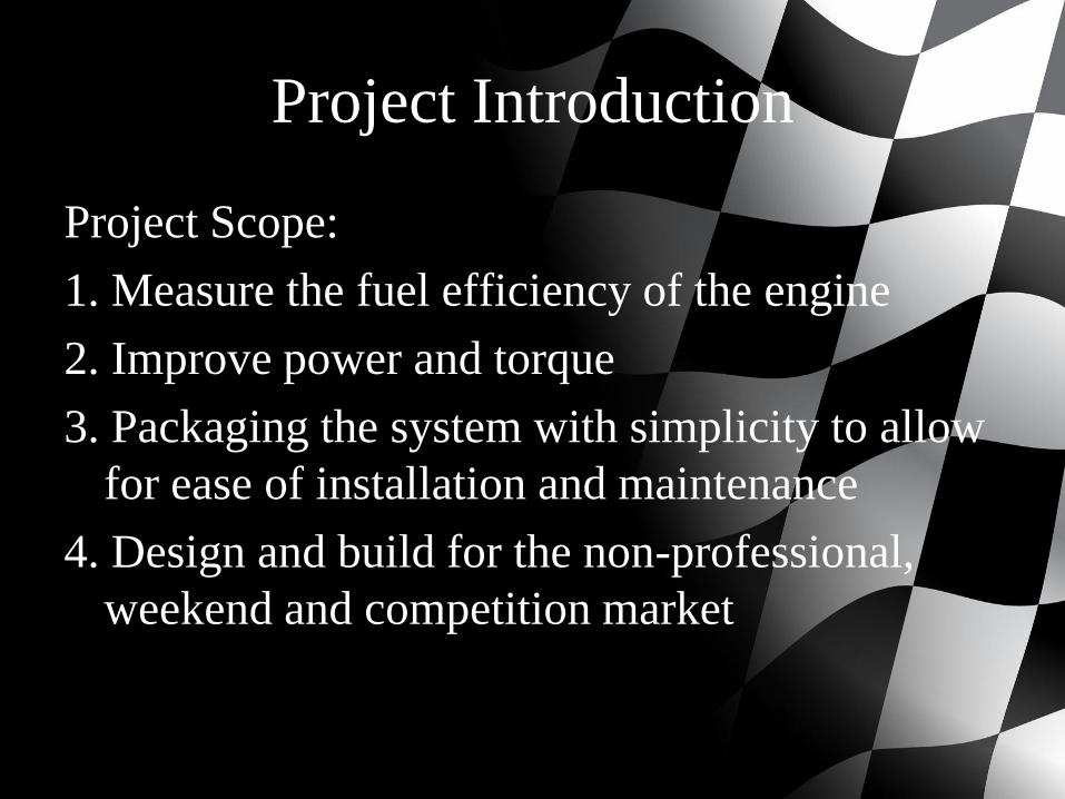
Project Introduction
Project Scope:
1. Measure the fuel efficiency of the engine
2. Improve power and torque
3. Packaging the system with simplicity to allow
for ease of installation and maintenance
4. Design and build for the non-professional,
weekend and competition market
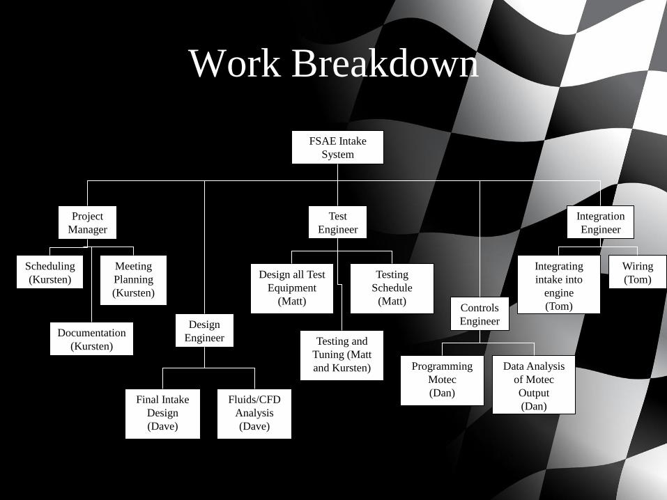
Work Breakdown
FSAE Intake
System
Project
Manager
Design
Engineer
Test
Engineer
Controls
Engineer
Integration
Engineer
Scheduling
(Kursten)
Meeting
Planning
(Kursten)
Documentation
(Kursten)
Final Intake
Design
(Dave)
Fluids/CFD
Analysis
(Dave)
Design all Test
Equipment
(Matt)
Testing and
Tuning (Matt
and Kursten)
Testing
Schedule
(Matt)
Programming
Motec
(Dan)
Data Analysis
of Motec
Output
(Dan)
Integrating
intake into
engine
(Tom)
Wiring
(Tom)
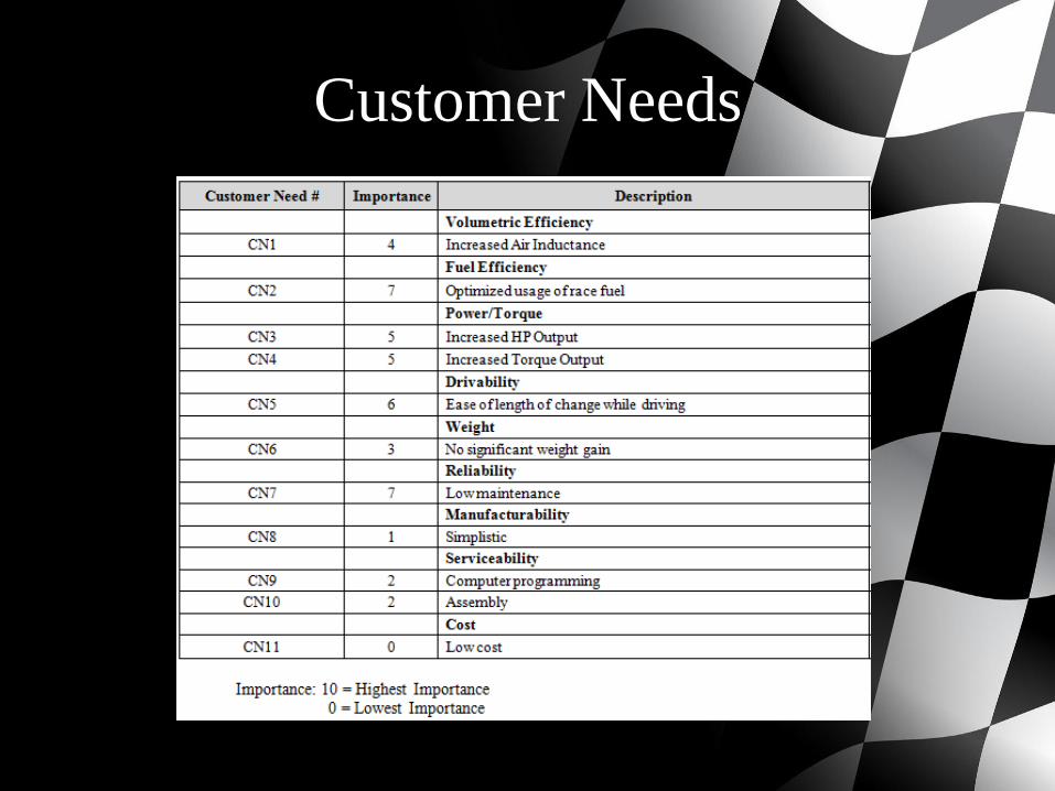
Customer Needs
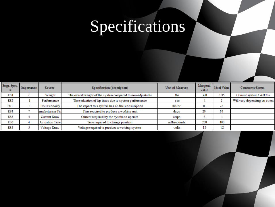
Specifications
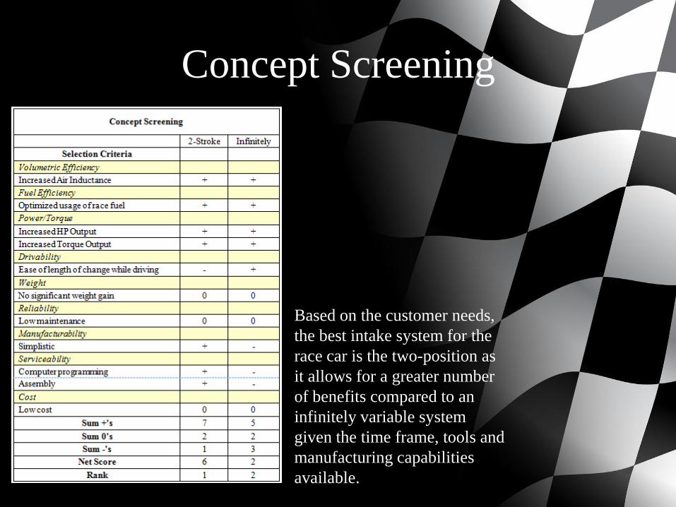
Concept Screening
Based on the customer needs,
the best intake system for the
race car is the two-position as
it allows for a greater number
of benefits compared to an
infinitely variable system
given the time frame, tools and
manufacturing capabilities
available.

Budget
Risks
Please see handout for list
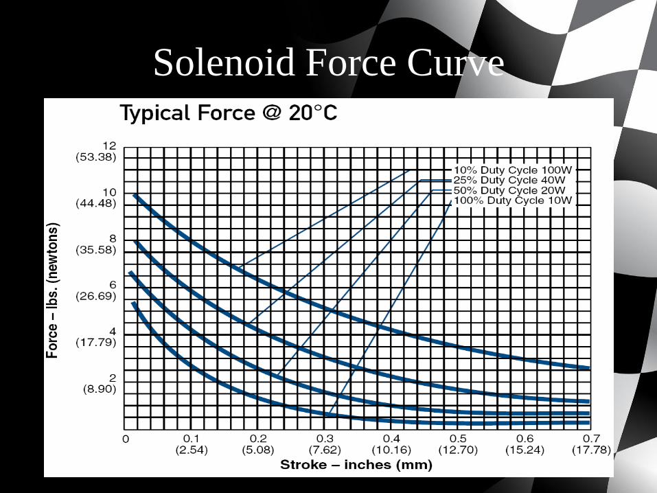
Solenoid Force Curve
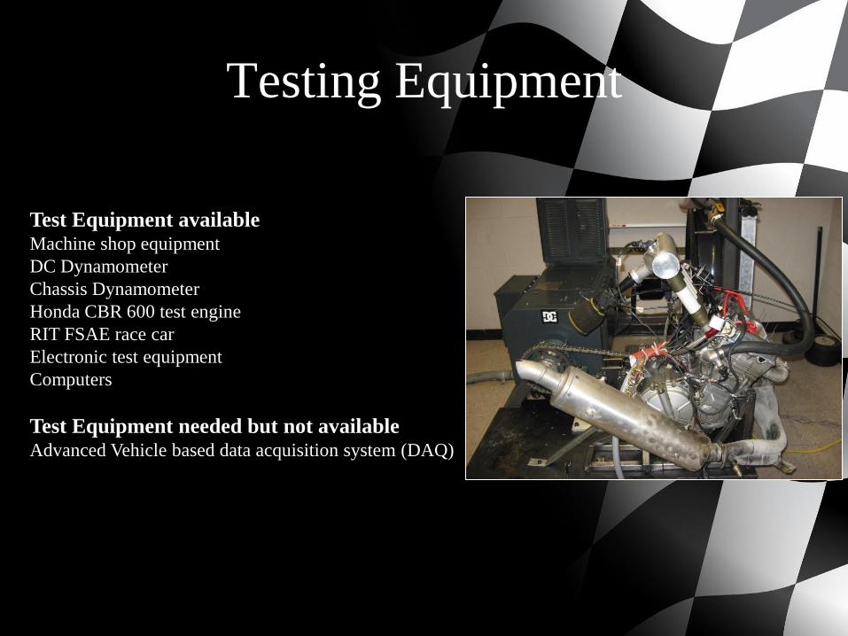
Testing Equipment
Test Equipment availableMachine shop equipment
DC Dynamometer
Chassis Dynamometer
Honda CBR 600 test engine
RIT FSAE race car
Electronic test equipment
Computers
Test Equipment needed but not availableAdvanced Vehicle based data acquisition system (DAQ)
TestingSub-System Breakdown
• Mechanical System
• The mechanical system is comprised of the sliding interface that allows the change in runner
length and the plenum that the runners interact with. This system must allow for the desired
change in length, not leak, maintain desired plenum volume, and comply with the FSAE
rulebook.
• Actuation System
• The actuation system will move the mechanical system based on inputs from the control
system. Actuation speed is critical for this application as transient times must be kept under
100ms. This system must also be able to gauge the system’s location.
• Control System
• The controls for this system will be fully integrated into the engine control unit (ECU) for the
vehicle. Using inputs such as RPM, throttle position, manifold pressure and current runner
length the control system will output a desired runner length to be achieved by the actuation
system.
• Supporting Systems
• The variable intake will interface with the engine on one end and a throttle/ restrictor
assembly on the other. Sufficient information on the flow characteristics of the throttle/
restrictor assembly will be needed to design and tune this system.
• The electrical requirements of the actuation system will be provided by the vehicle’s stator.
There is a limited amount of power available from this system, which must be taken into
account.
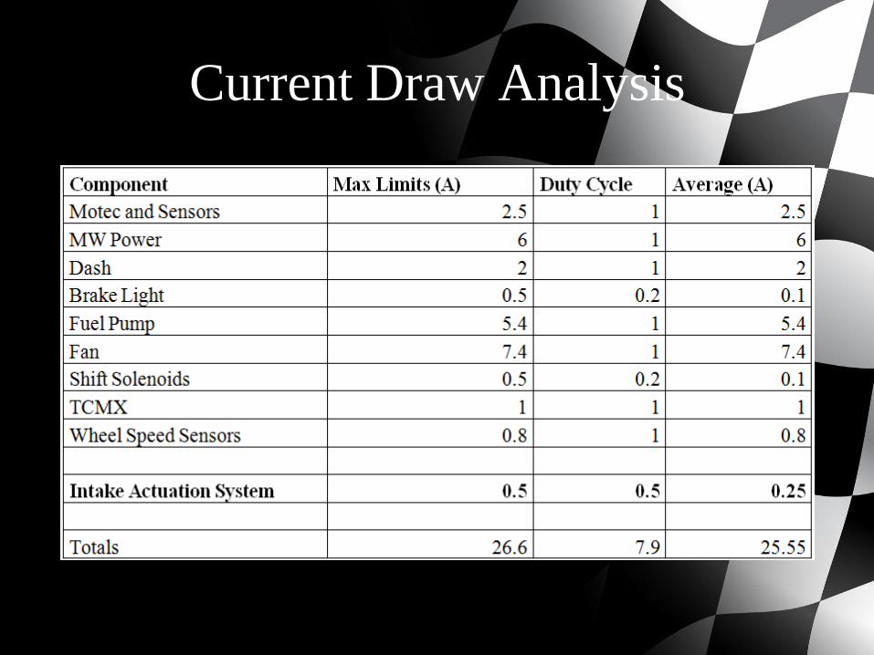
Current Draw Analysis
Preliminary Testing Results
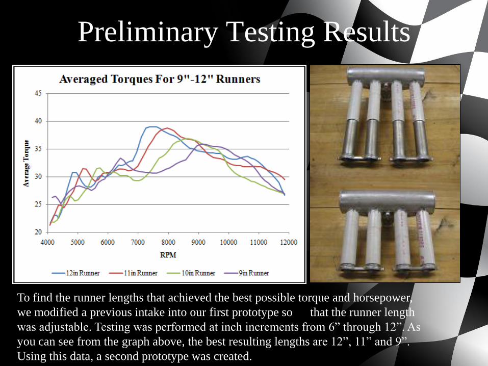
To find the runner lengths that achieved the best possible torque and horsepower,
we modified a previous intake into our first prototype so that the runner length
was adjustable. Testing was performed at inch increments from 6” through 12”. As
you can see from the graph above, the best resulting lengths are 12”, 11” and 9”.
Using this data, a second prototype was created.
Preliminary Testing Results
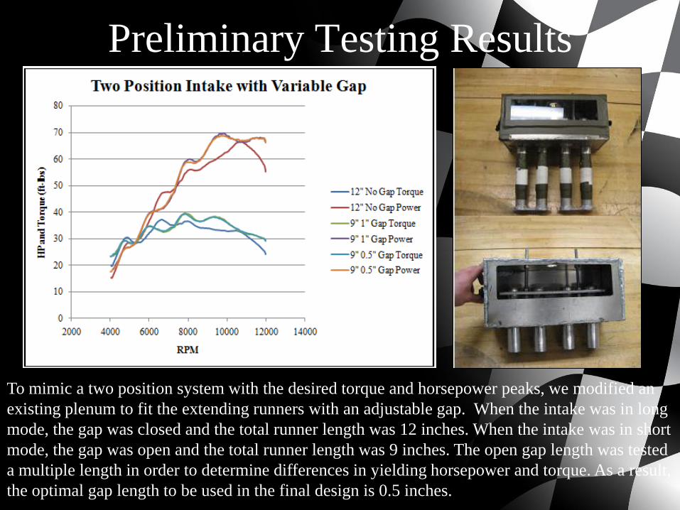
To mimic a two position system with the desired torque and horsepower peaks, we modified an
existing plenum to fit the extending runners with an adjustable gap. When the intake was in long
mode, the gap was closed and the total runner length was 12 inches. When the intake was in short
mode, the gap was open and the total runner length was 9 inches. The open gap length was tested
a multiple length in order to determine differences in yielding horsepower and torque. As a result,
the optimal gap length to be used in the final design is 0.5 inches.
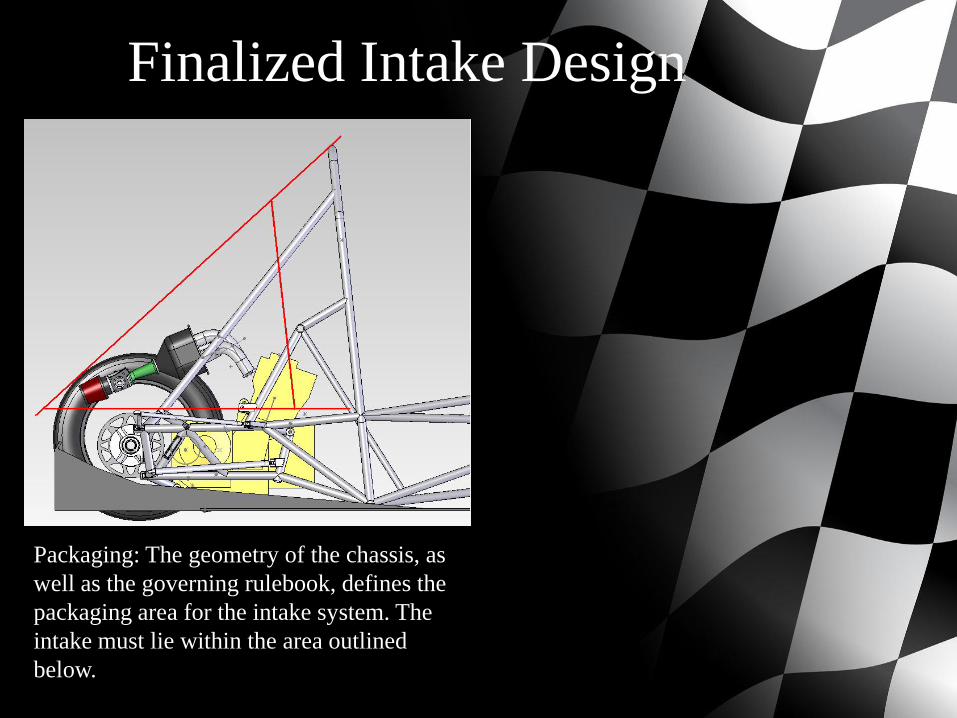
Finalized Intake Design
Packaging: The geometry of the chassis, as
well as the governing rulebook, defines the
packaging area for the intake system. The
intake must lie within the area outlined
below.
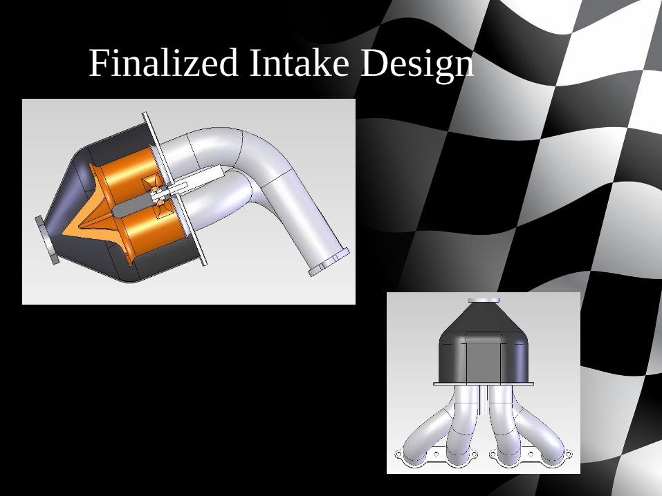
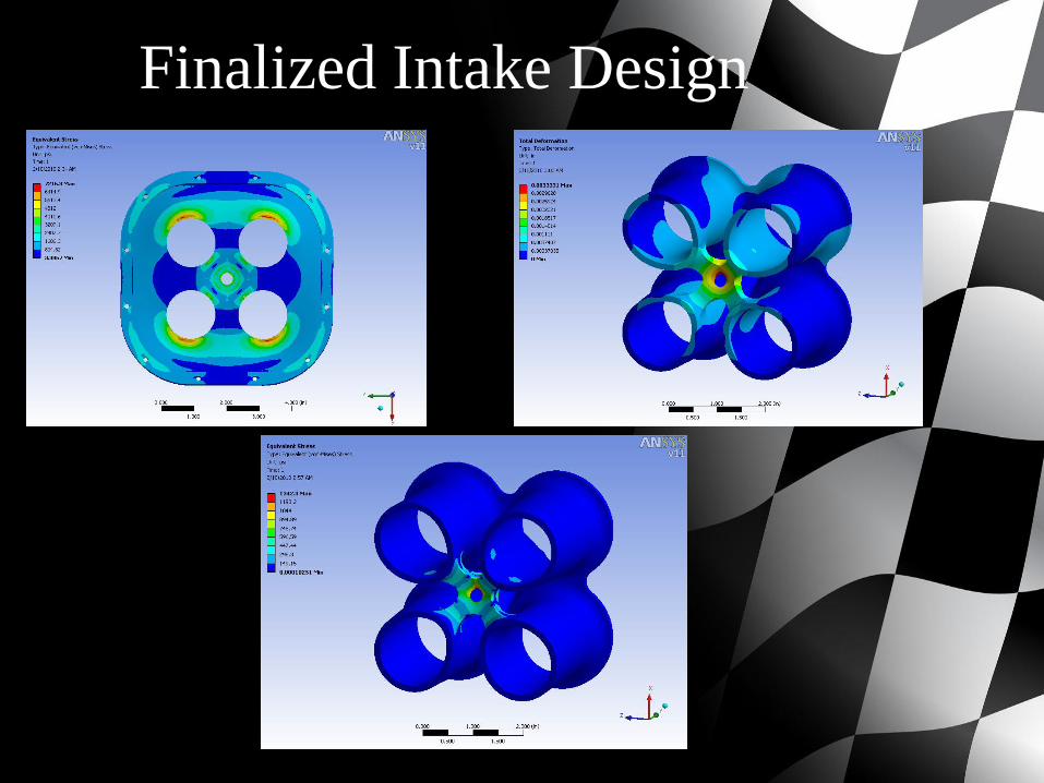
Finalized Intake Design
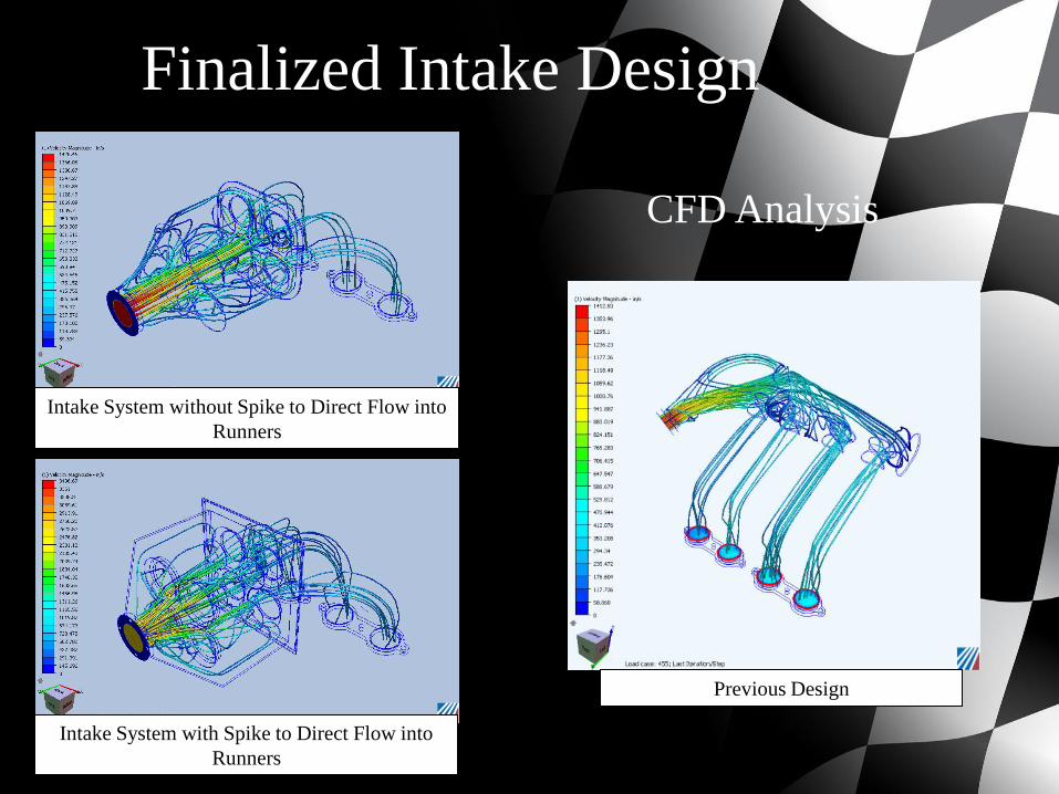
Finalized Intake Design
Intake System without Spike to Direct Flow into
Runners
Intake System with Spike to Direct Flow into
Runners
Previous Design
CFD Analysis
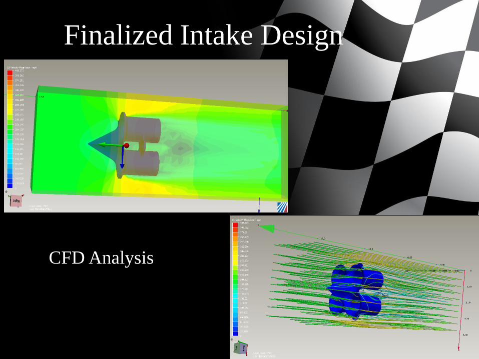
Finalized Intake Design
CFD Analysis
Finalized Intake Design
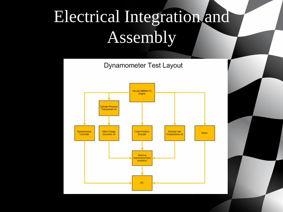
Electrical Integration and
Assembly
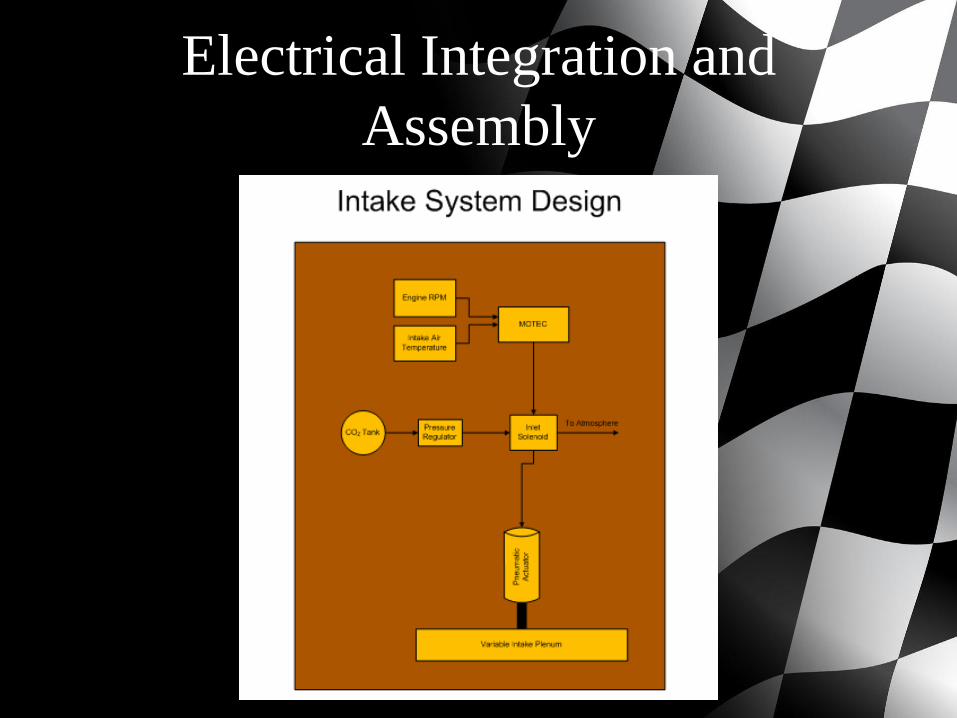
Electrical Integration and
Assembly
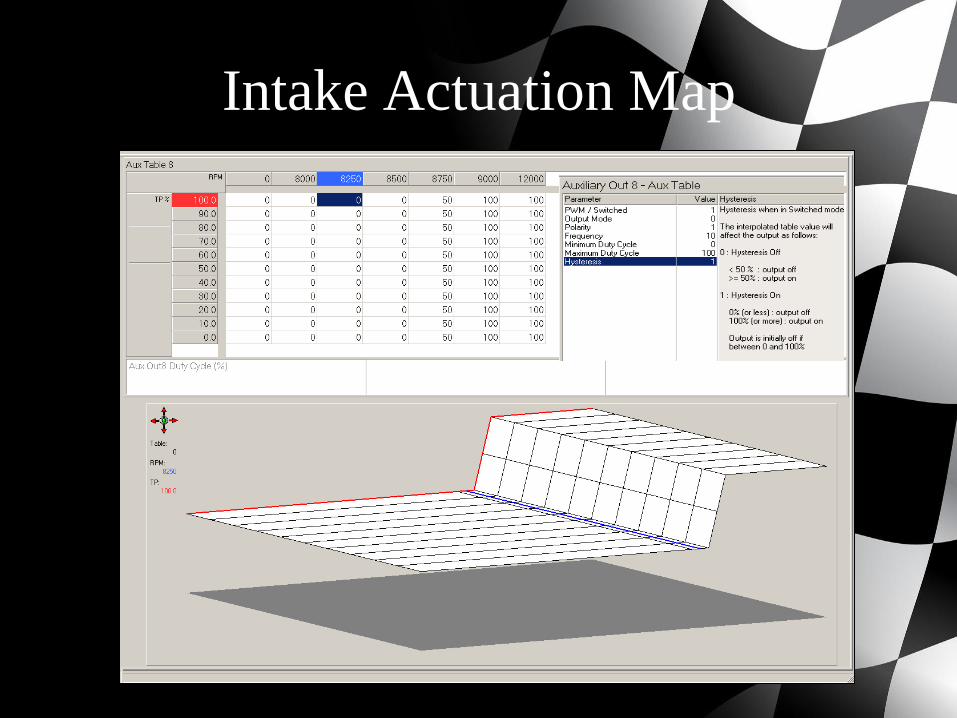
Intake Actuation Map
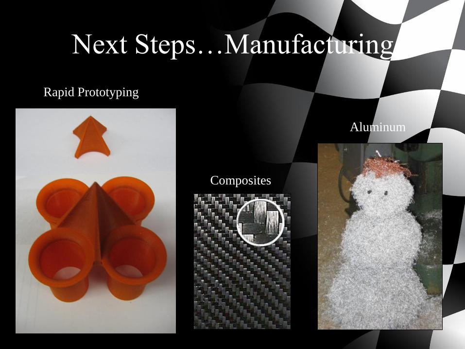
Next Steps…Manufacturing
Rapid Prototyping
Composites
Aluminum
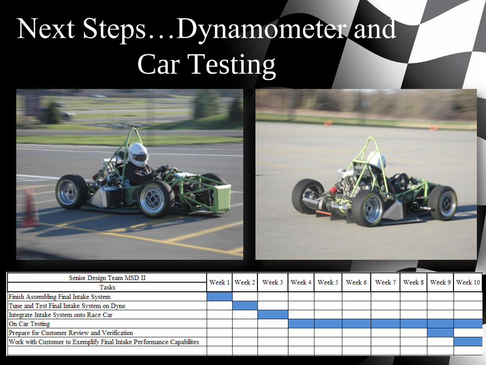
Next Steps…Dynamometer and
Car Testing
Questions?