Detailed description of GMPLS RSVP-TE signaling procedures for
42
December 30, 2002 1 Detailed description of GMPLS RSVP-TE signaling procedures for hardware implementation Version 0, Revision 1 December, 2002 Haobo Wang, Malathi Veeraraghavan, Ramesh Karri Polytechnic University [email protected], [email protected], [email protected]
Transcript of Detailed description of GMPLS RSVP-TE signaling procedures for

December 30, 2002 1
Detailed description of GMPLS RSVP-TE signaling procedures for hardware implementation
Version 0, Revision 1
December, 2002
Haobo Wang, Malathi Veeraraghavan, Ramesh KarriPolytechnic University
December 30, 2002 2
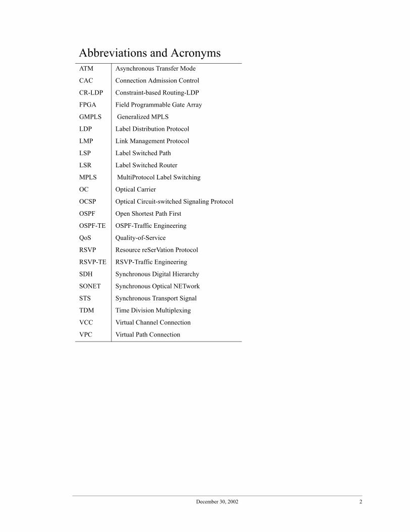
Abbreviations and AcronymsATM Asynchronous Transfer Mode
CAC Connection Admission Control
CR-LDP Constraint-based Routing-LDP
FPGA Field Programmable Gate Array
GMPLS Generalized MPLS
LDP Label Distribution Protocol
LMP Link Management Protocol
LSP Label Switched Path
LSR Label Switched Router
MPLS MultiProtocol Label Switching
OC Optical Carrier
OCSP Optical Circuit-switched Signaling Protocol
OSPF Open Shortest Path First
OSPF-TE OSPF-Traffic Engineering
QoS Quality-of-Service
RSVP Resource reSerVation Protocol
RSVP-TE RSVP-Traffic Engineering
SDH Synchronous Digital Hierarchy
SONET Synchronous Optical NETwork
STS Synchronous Transport Signal
TDM Time Division Multiplexing
VCC Virtual Channel Connection
VPC Virtual Path Connection
December 30, 2002 3
1. Introduction1
This document is a detailed design document for an FPGA implementation of theRSVP subset defined in [1]. Four messages are processed in the hardware signaling mod-ule, Path, Resv, PathTear, and ResvTear. As each message is received, after checking thechecksum to verify that no errors occurred, the module parses out objects and processesthese objects.
As objects are parsed, different fields of the objects are placed in registers. Section 2lists these registers. In addition, there are a few registers that are set at system initializationtime. We refer to these as “initialization registers.” Values set in these registers control thefunctions implemented in the hardware module.
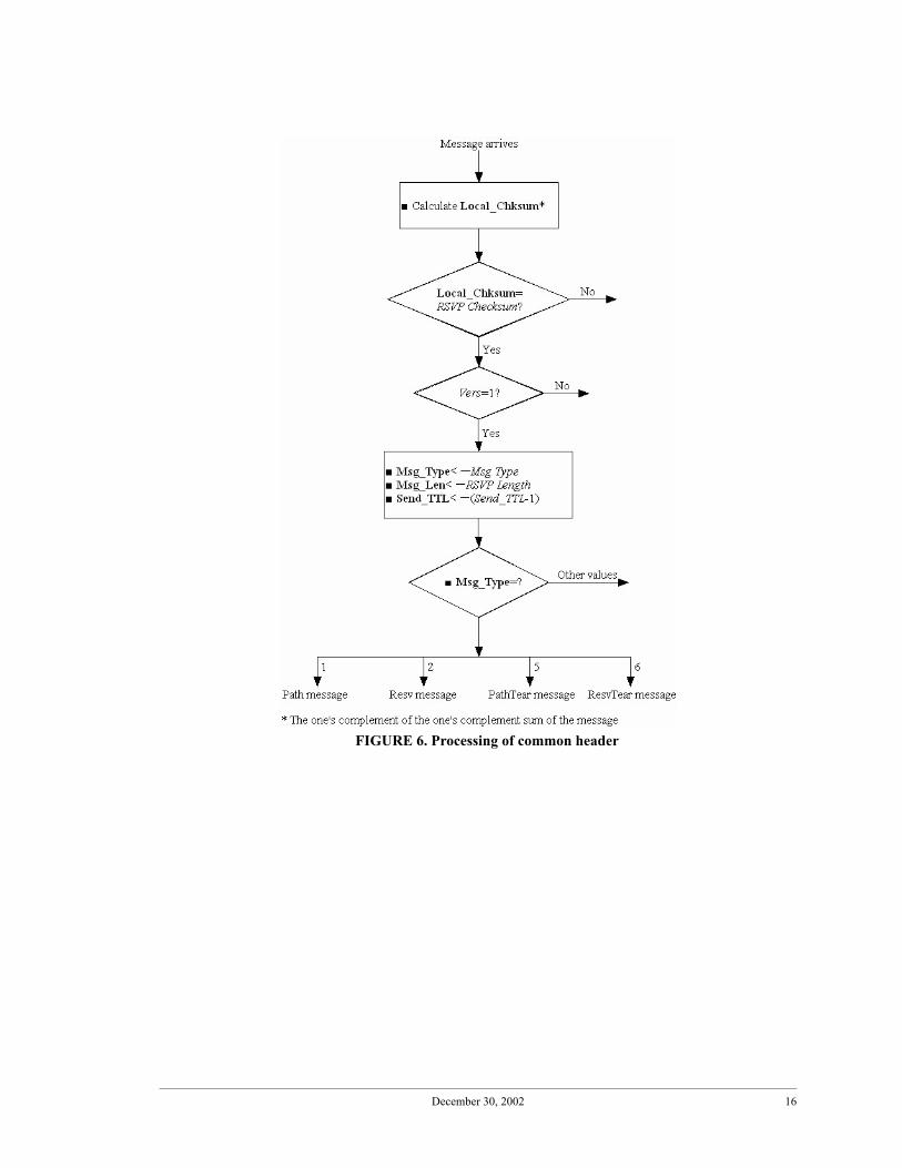
Some numbers are “hardwired” into the implementation instead of being set in initial-ization registers. For example, the hardware module handles four message types: 1, 2, 5, 6.Instead of setting these values in an initialization register and having the message proces-sor compare the message type value carried in an incoming message with these allowed-message-types, the implementation is hardwired to only accept these four message types.The reason for this design approach is to achieve low delays and low logic resource usage.In many such instances, we had to make design decisions between flexibility and perfor-mance.
Most of the signaling message processing consists of reading and writing data tables.We describe these data tables in Section 3. These tables reflect the functionality definedfor the RSVP subset in [1]. For example, the separation of control plane and user plane,allowing multiple interfaces between neighboring switches, allowing for logical linksbetween neighbors, etc. All data tables are initialized through a software module. Some ofthem are only read by the hardware signaling module while others are read and written.
Since RSVP allows objects to be placed in any order within messages, our designapproach is to have object processors start processing objects as they are parsed out mes-sages. In some cases, the processing of an object will have to wait for another object to beprocessed. This is indicated in the flow charts shown in Section 4.
This design is for a signaling engine that will be used in conjunction with a VitesseVSC9182 SONET switch chip. The VSC9182 is a switch with 64 OC12 inter-faces and operates at a crossconnect rate of OC1.
Of all the functionality specified as being supported in [1], the only change we made isto not support bandwidth negotiation in the hardware implementation. Thus, the hardwaresignaling module will check for the requested bandwidth on all interfaces to the next hopswitch; but if none of them have the requested bandwidth, it will pass the signaling mes-sage to the software signaling process for handling. We found this negotiation process tobe too complex for immediate hardware implementation.
1. This work is sponsored by a NSF grant, 0087487, and by NYSTAR (The New York Agency of Science, Technology and Academic Research) through the Center for Advanced Technology in Telecommunica-tions (CATT) at Polytechnic University.
64 64×

December 30, 2002 4
Figure 1 shows the prefixes and suffixes we used in this document.
FIGURE 1. Prefixes and suffixes used in this document

December 30, 2002 5
2. RegistersTABLE 1. Registers extracted from messages
RegisterWidth(bit) Description
Msg_Type 8 Message type, Msg Type in Common HeaderMsg_Len 16 Message length, RSVP length in Common HeaderLocal_Chksum 16 Locally calculated checksumSend_TTL 8 Send TTL, Send_TTL in Common HeaderSrc_IP_Addr 32 Source IP address, IPv4 tunnel sender address in
SENDER_TEMPLATE object within Path message or FILTER_SPEC object within Resv message.
LSP_ID 16 LSP ID in SENDER_TEMPLATE object within Path message or FILTER_SPEC object within Resv message.
Dest_IP_Addr 32 Destination IP address, IPv4 tunnel end point address in SES-SION object within Path/Resv message
Tunnel_ID 16 Tunnel ID in SESSION object within Path/Resv messageExt_Tunnel_ID 32 Extended tunnel ID in SESSION object within Path/Resv mes-
sagePre_IP_Addr_Ctrl 32 Previous IP address on control plane, IPv4 Previous Hop Address
in RSVP_HOP object within Path messageNext_IP_Addr_Ctrl 32 Next IP address on control plane, the result of Data/Control
Mapping table lookupLIH 32 Logical Interface Handle in RSVP_HOP object within Path
messagePre_IP_Addr_User 32 Previous IP address on user plane, IP Address in IF-INDEX TLV
within Path messagePre_IF_ID_User 32 Upstream node output interface ID, Interface ID in IF-INDEX
TLV within Path messageTmp_IP_Addr_User 32 IP Address in IF-INDEX TLV within Resv messageTmp_IF_ID_User 32 Interface ID in IF-INDEX TLV within Resv messageTmp_IP_Addr_Ctrl 32 IP Address in IPv4 Next Hop Addr. field of the RSVP_HOP
object within Resv messageNext_IP_Addr_User 32 Next hop IP address, the result of Routing table lookupSeq_Num 4 Sequence number of the links between two neighboring LSRs.Incoming_IF_ID_User 32 Incoming interface ID, the result of Incoming Connectivity table
lookupOutgoing_IF_ID_User 32 Outgoing interface ID, the result of Outgoing Connectivity/
CAC table lookupIncoming_PHY_ID 8 Incoming physical interface IDOutgoing_PHY_ID 8 Outgoing physical interface IDIncoming_Assigned_Timeslots
12 Timeslots assigned to a certain incoming logical link
Outgoing_Assigned_Timeslots
12 Timeslots assigned to a certain outgoing logical link

December 30, 2002 6
Incoming_Label(s) 32 Generalized label(s) for the incoming interface, locally allocatedOutgoing_Label(s) 32 Generalized label(s) for the outgoing interface, received from
downstream LSRSignal_Type 8 Signal Type in SENDER_TSPEC object within Path message or
FLOWSPEC object within Resv messageRCC 8 Requested Contiguous Concatenation in SENDER_TSPEC
object within Path message or FLOWSPEC object within Resv message
NCC 16 Number of Contiguous Concatenation in SENDER_TSPEC object within Path message or FLOWSPEC object within Resv message
NVC 16 Number of Virtual Concatenation in SENDER_TSPEC object within Path message or FLOWSPEC object within Resv mes-sage
MT 16 Multiplier in SENDER_TSPEC object within Path messageState 4 Current state of an LSPAvail_BW 12 Available bandwidth, the result of Incoming CAC table lookup
or Outgoing Connectivity/CAC table lookupLSP_Enc_Type 8 LSP Encoding Type in LABEL_REQUEST object within Path
messageSwitching_Type 8 Switching Type in LABEL_REQUEST object within Path mes-
sageG-PID 16 Generalized PID in LABEL_REQUEST object within Path
messageRefresh_Period 32 Refresh Period in TIME_VALUES object within Path messageStyle 5 Option vector in STYLE object within Resv message
TABLE 2. Initialization registers
Registers/ConstantWidth(bits)
Init value Meaning
Initialized_LSP_Enc_Type 8 5 SDH ITU-T G.707/SONET ANSI T1.105Initialized_Switching_Type 8 100 Time-Division-Multiplex Capable (TDM)Local_IP_Addr_User 32 - Local IP address on the user planeLocal_IP_Addr_Ctrl 32 - Local IP address on the control planeSupported_ST 8 1 The crossconnect rate of the switch - 1 means OC1
TABLE 1. Registers extracted from messages
RegisterWidth(bit) Description

December 30, 2002 7
3. Data tablesFigure 2 is an illustrative network that shows the possibilities accommodated in our
signaling engine. Figure 3 shows the signaling message flow while setting up a circuit.Itshows the upstream-downstream relation between switches on the path of a connection.
Network of IP routers (not necessarily the Internet;could be a specially designed IP network just forsignaling traffic)
Switch
Signalingengine
Switch II
Signalingengine
Client
Switch I
Signalingengine
Switch III
Signalingengine
FIGURE 2. Network used for illustrative examples; shows that (i) switches can be connected via many user-plane interfaces (ii) logical links can be provisioned between non-adjacent switches (iii) a signaling engine may have many signaling links leading to the connectionless signaling network (IP network)
Logical link
Server
Server-to-clientSONETunidirectionalcircuit
1 234
6 12
34 5
7
Physical interface: 5 Physical interface: 56
Physicalinterface: 7
Physicalinterface: 2
FIGURE 3. Signaling message flow for setting up a unidirectional circuit; SW1 is upstream relative to SW2, and SW2 is upstream relative to SW3 because of the direction of the circuit; the data sender initiates circuit setup
Upstream DownstreamUpstream
SwitchEnd Device SW 3
Switch SW 1
Switch
SW 4
Switch
SW 2
Switch
SW 5
1.Path 2.Path 3.Path 4.Path
End Device
7.Resv 6.Resv 5.Resv 8.Resv
9. Connection (circuit or virtual circuit) established
Downstream

December 30, 2002 8
3.1 Routing table
Routing table, as shown in Table 3, is initialized and maintained by a software routingprocess (OSPF-TE for GMPLS). It is read-only to the hardware signaling module. TheNext_IP_Addr_User is the user-plane IP address for the next hop switch through whichthe destination IP address can be reached. Lookup of this field is a longest prefix matchbecause Dest_IP_Addr can be an IP address prefix or a full 32-bit destination address. Ingeneral, a routing table can have alternative next hop switches. However, we do not imple-ment multiple routing table lookups in the hardware signaling module for simplicity rea-sons. This module will attempt only one route; if resources are not available, it will passoff the message to the software signaling process. For a subsequent release, we will recon-sider this design decision.
3.2 Incoming Connectivity table
The Incoming Connectivity table, shown in Table 4, is initialized and updated by aLink Management Protocol (LMP). It is read-only to the hardware signaling module. Itshows how the interface numbers used by a neighbor maps to an incoming interface num-ber and the corresponding physical interface. The incoming assigned timeslots column is abitmap with 1s for timeslots assigned to this logical interface and 0 for other timeslots.
Using the example shown in Figure 2, the incoming connectivity table at switch II willhave entries as shown in Table 5. Here we assume that timeslots 1-3 of the physical inter-face 5 are terminated at switch II while the remaining timeslots 4-12 (we assume all inter-faces are OC12s given our implementation target, a VSC9182 SONET switch) are usedfor the logical link passing through switch II to terminate at switch III. On the other hand,we assume that all 12 timeslots of physical interface 2 terminate at switch II. In caseswhere all timeslots of a physical interface terminate at a switch, we use the same numberfor physical interface as for the interface ID used in signaling messages. Otherwise, a log-ical interface number that maps to a physical interface and timeslots is used in signalingmessages to identify logical links.
TABLE 3. Routing table
Index Return valueDest_IP_Addr Next_IP_Addr_User
TABLE 4. Incoming Connectivity table
Index Return valuePre_IP_Addr_User Pre_IF_ID_User Incoming_IF
_ID_UserIncoming_PHY_ID Incoming_Assigned
_Timeslots
TABLE 5. Incoming Connectivity table at switch II in Figure 2
Index Return valuePre_IP_Addr_User Pre_IF_ID_User Incoming_IF
_ID_UserIncoming_PHY_ID Incoming_Assigned
_TimeslotsSwitch I IP address 4 2 2 1111 1111 1111Switch I IP address 6 1 5 1110 0000 0000
December 30, 2002 9
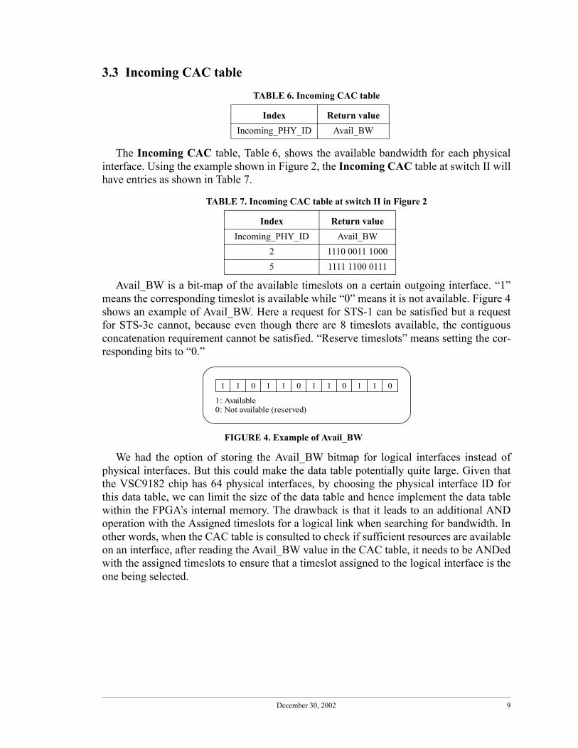
3.3 Incoming CAC table
The Incoming CAC table, Table 6, shows the available bandwidth for each physicalinterface. Using the example shown in Figure 2, the Incoming CAC table at switch II willhave entries as shown in Table 7.
Avail_BW is a bit-map of the available timeslots on a certain outgoing interface. “1”means the corresponding timeslot is available while “0” means it is not available. Figure 4shows an example of Avail_BW. Here a request for STS-1 can be satisfied but a requestfor STS-3c cannot, because even though there are 8 timeslots available, the contiguousconcatenation requirement cannot be satisfied. “Reserve timeslots” means setting the cor-responding bits to “0.”
We had the option of storing the Avail_BW bitmap for logical interfaces instead ofphysical interfaces. But this could make the data table potentially quite large. Given thatthe VSC9182 chip has 64 physical interfaces, by choosing the physical interface ID forthis data table, we can limit the size of the data table and hence implement the data tablewithin the FPGA’s internal memory. The drawback is that it leads to an additional ANDoperation with the Assigned timeslots for a logical link when searching for bandwidth. Inother words, when the CAC table is consulted to check if sufficient resources are availableon an interface, after reading the Avail_BW value in the CAC table, it needs to be ANDedwith the assigned timeslots to ensure that a timeslot assigned to the logical interface is theone being selected.
TABLE 6. Incoming CAC table
Index Return valueIncoming_PHY_ID Avail_BW
TABLE 7. Incoming CAC table at switch II in Figure 2
Index Return valueIncoming_PHY_ID Avail_BW
2 1110 0011 10005 1111 1100 0111
1 1 0 1 1 0 1 1 0 1 1 0
1: Available0: Not available (reserved)
FIGURE 4. Example of Avail_BW

December 30, 2002 10
3.4 Outgoing Connectivity table
The Outgoing Connectivity table, Table 8, shows the outgoing interfaces leading toneighboring switches. It also maintains mapping of logical interface IDs to physical inter-face IDs and corresponding timeslots. Since a switch may have multiple links to a neigh-bor, there may be many rows in this data table corresponding to a singleNext_IP_Addr_User. Hence we have the Seq_Num column allowing the hardware signal-ing module to search this table multiple times until it finds an interface to the neighboringswitch with sufficient available resources or exhausts all interfaces to the neighboringswitches.
An example Outgoing Connectivity table is shown for switch I in Figure 2. Timeslots1-3 on physical interface 5 at switch I terminate at switch II while the remaining are routedthrough as a logical link to Switch III.
3.5 Outgoing CAC table
The Outgoing CAC table, Table 10, is similar to the Incoming CAC table. It showsavailable time slots for different outgoing interfaces. Table 11 shows an example Outgo-ing CAC table.
TABLE 8. Outgoing Connectivity table
Index Return valueNext_IP_Addr_User Seq_Num Outgoing_IF_ID
_UserOutgoing_PHY_ID
Outgoing_Assigned_T
imeslots
TABLE 9. Outgoing Connectivity table for switch I in Figure 2
Index Return valueNext_IP_Addr_User Seq_Num Outgoing_I
F_ID_UserOutgoing_PHY_ID
Outgoing_Assigned_Timeslots
Switch II IP address 0 6 5 1110 0000 0000Switch II IP address 1 4 4 1111 1111 1111Switch III IP address 0 7 5 0001 1111 1111
TABLE 10. Outgoing CAC table
Index Return valueOutgoing_PHY_ID Avail_BW
TABLE 11. Outgoing CAC table for switch I in Figure 2
Index Return valueOutgoing_PHY_ID Avail_BW
5 1111 1111 10004 0110 0011 11115 1111 1111 1111

December 30, 2002 11
3.6 Data/Control Mapping table
Unlike packet-switched MPLS networks, where implicit in-band signaling is used andthere is a one-to-one association between control channels and data links, circuit-switchednetworks generally require out-of-band signaling and hence a separation of control chan-nels from corresponding data links. The Data/Control Mapping table, Table 12, is usedto map user plane IP addresses of neighboring switches to the corresponding control planeIP addresses.
Our implementation supports multiple data links between two neighboring LSRs, asillustrated in Figure 2. A switch may also have multiple control plane interfaces as shownin Figure 2 for switch II. We assume that load balancing of signaling load across multiplecontrol plane interfaces will be done outside the signaling module and appropriate datadownloaded to this Data/Control Mapping table. We assume that there is only oneNext_IP_Addr_Ctrl associated with each next-hop switch.
3.7 State table
The State table, as shown in Table 13, is the most complex of all the data tables. TheState table consists of two parts: the index part, which includes the Src_IP_Addr, LSP_ID,Dest_IP_Addr, Tunnel_ID, Ext_Tunnel_ID, and uniquely identifies an LSP, and a returnvalue part, which consists of many parameters about the LSP. The appendix explains ourreasoning for using the five-tuple index as the global connection reference.
Unlike in “stateless” connectionless networks, in connection-oriented networks, aswitch needs to maintain state information for each LSP. We defined three states for anLSP as shown in Figure 5. Before a Path message arrives, the LSP does not exist, and ishence in the NULL state. After a Path message is received, a next hop IP address is deter-mined and resources are reserved. The LSP then enters the RESERVED state. When the
TABLE 12. Data/Control Mapping table
Index Return valueNext_IP_Addr_User Next_IP_Addr_Ctrl
TABLE 13. State table
Index (Global connection reference)
Return value
Control plane Data planeSrc_IP_Addr
LSP_ID
Dest_IP_Addr
Tunnel_ID
Ext_Tunnel_ID
Pre_IP_Addr_Ctrl
LIH Next_IP_Addr_Ctrl
Pre_IP_Addr_User
Pre_IF_ID_User
Incoming_Assigned_Timeslots
Outgoing_Assigned_Timeslots
Return value (con’t)
Data plane (con’t)Incoming_IF_ID_User
Incoming_PHY_ID
Incoming_Label(s)
Next_IP_Addr_User
Outgoing_IF_ID_User
Outgoing_PHY_ID
Outgoing_Label(s)
Traffic_Spec
State

December 30, 2002 12
Resv message arrives, timeslots (labels) are allocated and the LSP enters the ESTAB-LISHED state.
The reason we chose the values 1, 2 and 4 for the numerical values of the states isbecause we chose the “one-hot” style for the State register. There are three common waysfor encoding information such as State in a register: (i) Binary, which uses all possiblecombinations. For example, if there are 8 different states, we would use 3 bits to representthese 8 states. The benefit of this style is that it the size of the State register is small. Thedrawback is that this style needs a decoder. (ii) One-hot, which uses the same number ofbits as the number of states. Using the same example, if there are 8 states, we would needan 8-bit register. Each bit corresponds to a state. The benefit is that no decoder is requiredand hence updating the State register will be faster than with the binary style. Given thatFPGAs have an abundance of registers, the one-hot style is popular. (iii) Gray-coding,which uses the Gray-code to represent different states. The benefit is that it needs only a 1-bit change between two states, which avoids possible glitches. The drawback is that it isslower than the one-hot style and consumes more resources than the binary style.
FIGURE 5. State transition diagram
December 30, 2002 13
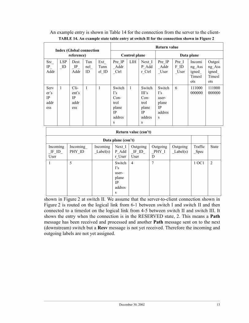
An example entry is shown in Table 14 for the connection from the server to the client-
shown in Figure 2 at switch II. We assume that the server-to-client connection shown inFigure 2 is routed on the logical link from 6-1 between switch I and switch II and thenconnected to a timeslot on the logical link from 4-5 between switch II and switch III. Itshows the entry when the connection is in the RESERVED state, 2. This means a Pathmessage has been received and processed and another Path message sent on to the next(downstream) switch but a Resv message is not yet received. Therefore the incoming andoutgoing labels are not yet assigned.
TABLE 14. An example state table entry at switch II for the connection shown in Figure 2
Index (Global connection reference)
Return value
Control plane Data planeSrc_IP_Addr
LSP_ID
Dest_IP_Addr
Tunnel_ID
Ext_Tunnel_ID
Pre_IP_Addr_Ctrl
LIH Next_IP_Addr_Ctrl
Pre_IP_Addr_User
Pre_IF_ID_User
Incoming_Assigned_Timeslots
Outgoing_Assigned_Timeslots
Server’s IP address
1 Cli-ent’s IP address
1 1 Switch I’s Con-trol plane IP address
1 Switch III’s Con-trol plane IP address
Switch I’s user-plane IP address
6 111000000000
111000000000
Return value (con’t)
Data plane (con’t)Incoming_IF_ID_User
Incoming_PHY_ID
Incoming_Label(s)
Next_IP_Addr_User
Outgoing_IF_ID_User
Outgoing_PHY_ID
Outgoing_Label(s)
Traffic_Spec
State
1 5 Switch I’s user-plane IP address
4 7 1 OC1 2

December 30, 2002 14
4. ProceduresWhen a message is parsed, fields from within objects are stored into registers. For field
names consult the message specifications in [1]. For register names, see Section 2. Thenotation used to represent a data table lookup is Output registers<-F (Data table name,Input registers). The function F represents a lookup of the data table identified by thefirst argument. The row corresponding to which the current values in the Input registers(identified in the arguments to function F) match the values in the corresponding columnsof the data table is selected through this lookup. We chose the same names for registersand columns in data tables. The values returned from the data table lookup is stored in theOutput registers.
Four actions are required to set up a connection: (i) look up routing table for next hop,(ii) run CAC algorithms to determine if enough resources are available, (iii) select avail-able timeslots/wavelengths, and (iv) program the switch fabric. The first step has to beperformed in the forward direction when a Path message is received. Resource reserva-tion for multicast sessions in RFC 2205 was designed to be handled in the reverse direc-tion because a receiver joins a multicast tree when needed. This implies that a switchshould maintain resource availability for its incoming interfaces and carry out steps 2, 3, 4in the reverse direction. However, in GMPLS networks, because of the introduction of aseparation of control-plane and user-plane interfaces, reference [5] states that the upstreamnode needs to select the outgoing interface for the connection. This means a switch shouldkeep resource availability for its outgoing interfaces, and should perform CAC to checkthat there are sufficient resources before selecting an interface (see Outgoing Connectiv-ity/CAC table in Section 3.4).
According to RFC 3209, the downstream switch selects the label though the upstreamswitch can suggest a label in the Path message. GMPLS allows for the Path message tocarry a suggested label and/or label set objects. However, in the subset we defined forhardware implementation, we do not implement these optional objects. Hence, in ourimplementation, steps 3 and 4 are handled in the reverse direction when a Resv message isreceived.
Figs. 6-30 provide the detailed flow charts for processing the four signaling messagesand their associated objects. We use the following notation:1. names of fields within RSVP message objects are identified in italics2. register names, data table names and messages are identified in boldface.
To parse out objects and fields within objects, we refer implementors to [1], whichspecifies the exact bit locations of object fields. RSVP objects follow the TLV (Tag-Length-Value) structure. Hence to parse out the value in a field within an object, in orderto copy the value into a register, the length field should be read first to identify the locationof the appropriate bits (as specified in [1]).
We note that there is potential for a conflict to arise given the current GMPLS signalingspecifications in which the Suggested Label object in Path message is left as optional.Consider the following scenario. An outgoing logical interface from a switch has fourassigned timeslots, say 111 100 000 000, out of a possible 12 timeslots on an OC12 inter-face. Say the first call requests an OC1; the upstream switch tentatively reserves the first

December 30, 2002 15
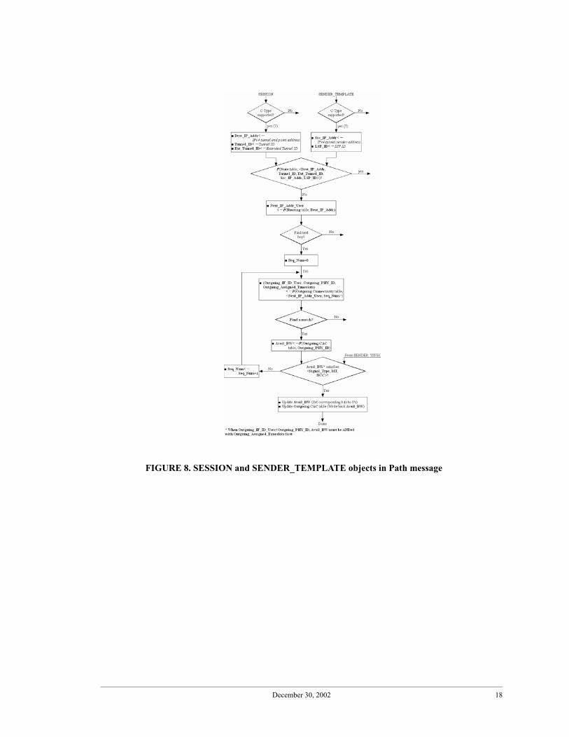
time slot. It sets the Avail_BW in the Outgoing CAC table for the corresponding physicalinterface to be 011 100 000 000 (ignore the values in the last 8 bits). This update is shownin Figure 8. Say a second call, one that requests an OC3c arrives next, and needs to berouted on this same outgoing logical interface. The switch will then make a tentative reser-vation of the remaining time slots and change Avail_BW to all zeros. If the downstreamswitch returns a Label for this interface in its Resv message different from time slot 1 forthe first call, say it selects time slot 2, then the second call for which a tentative reservationwas made can no longer be accommodated because the latter requires a concatenatedassignment. This will result in an error condition needing software intervention. Hence,we recommend the addition of the Suggested Label object in Path messages to force thedownstream switch to select an appropriate label. This is the result of the IETF communitystarting with RSVP, which was developed as a signaling protocol for receiver-initiatedadditions to a multicast tree, and growing it into a signaling protocol for GMPLS net-works. In GMPLS networks, where hard resource reservations of timeslots and wave-lengths are necessary, a reservation needs to be made in the forward direction. In thisversion of this document, we have not included the Suggested Label, but will do so in asubsequent release or find another solution to this problem.
December 30, 2002 16
FIGURE 6. Processing of common header

December 30, 2002 17
FIGURE 7. Processing of Path message
December 30, 2002 18
FIGURE 8. SESSION and SENDER_TEMPLATE objects in Path message

December 30, 2002 19
FIGURE 9. Processing of RSVP_HOP object in Path message

December 30, 2002 20
FIGURE 10. Processing of TIME_VALUES object in any message
FIGURE 11. Processing of SENDER_TSPEC object in Path message

December 30, 2002 21
FIGURE 12. Processing of LABEL_REQUEST object in Path message

December 30, 2002 22
After processing all the objects in a Path message, the state table is updated by copyingvalues from the registers shown in the right-hand column of table in the following manner:
State table column Register
Src_IP_Addr Src_IP_Addr
LSP_ID LSP_ID
Dest_IP_Addr Dest_IP_Addr
Tunnel_ID Tunnel_ID
Ext_Tunnel_ID Ext_Tunnel_ID
Pre_IP_Addr_Ctrl Pre_IP_Addr_Ctrl
LIH LIH
Next_IP_Addr_Ctrl Next_IP_Addr_Ctrl
State State (=2)
Pre_IP_Addr_User Pre_IP_Addr_User
TABLE 15. Updating State table after processing a Path message
FIGURE 13. At the end of Path message processing

December 30, 2002 23
To create the outgoing Path message, the hardware signaling module should constructa message following the details of the object formats from [1]. The values for all thesefields needed should be copied from corresponding registers. The register names are obvi-ous for all objects except the RSVP_HOP object. The registers to be used to construct theRSVP_HOP object are shown in Figure 14.
The destination IP address for the Path message should be obtained from theNext_IP_Addr_Ctrl register.
Pre_IF_ID_User Pre_IF_ID_User
Incoming_IF_ID_User Incoming_IF_ID_User
Incoming_PHY_ID Incoming_PHY_ID
Incoming_Label(s) NULL
Incoming_Assigned_Timeslots
Incoming_Assigned_Timeslots
Next_IP_Addr_User Next_IP_Addr_User
Outgoing_IF_ID_User Outgoing_IF_ID_User
Outgoing_PHY_ID Outgoing_PHY_ID
Outgoing_Label(s) NULL
Outgoing_Assigned_Timeslots
Outgoing_Assigned_Timeslots
Traffic_Spec <Signal_Type, RCC, NCC, NVC, MT>
TABLE 15. Updating State table after processing a Path message
FIGURE 14. Assemble new Path message

December 30, 2002 24
FIGURE 15. Processing of Resv message

December 30, 2002 25
FIGURE 16. Processing of SESSION and FILTER_SPEC objects in Resv message

December 30, 2002 26
** Extract from Page 39, RFC 2205: “The NHOP (i.e., the RSVP_HOP) object con-tains the IP address of the interface through which the Resv message was sent and the LIHfor the logical interface on which the reservation is required.”
** Extract from Page 22, RSVP-TE for GMPLS [7]: “A node receiving one or moreTLVs in a Path message saves their values and returns them in the HOP objects of subse-quent Resv messages sent to the node that originated the TLVs.”
G 1 i f S O i

December 30, 2002 27
FIGURE 18. Processing of STYLE object in any message
FIGURE 19. Processing of FLOWSPEC object in Resv message

December 30, 2002 28
FIGURE 20. Processing of LABEL object in Resv message

December 30, 2002 29
FIGURE 21. At the end of Resv message processing
FIGURE 22. Assemble new Resv message

December 30, 2002 30
The RSVP_HOP object in PathTear and ResvTear message and the FLOWSPEC objectin ResvTear message can simply be discarded. We could process the object fields andcompare the values with those stored for the connection in the state table. This may per-haps be implemented but is omitted here in the detailed procedure descriptions because itis relatively straightforward.
FIGURE 23. Processing of PathTear message

December 30, 2002 31
FIGURE 24. Processing of SESSION and SENDER_TEMPLATE objects in PathTear message

December 30, 2002 32
FIGURE 25. At the end of PathTear message processing
FIGURE 26. Assemble new PathTear message

December 30, 2002 33
FIGURE 27. Processing of ResvTear message
December 30, 2002 34
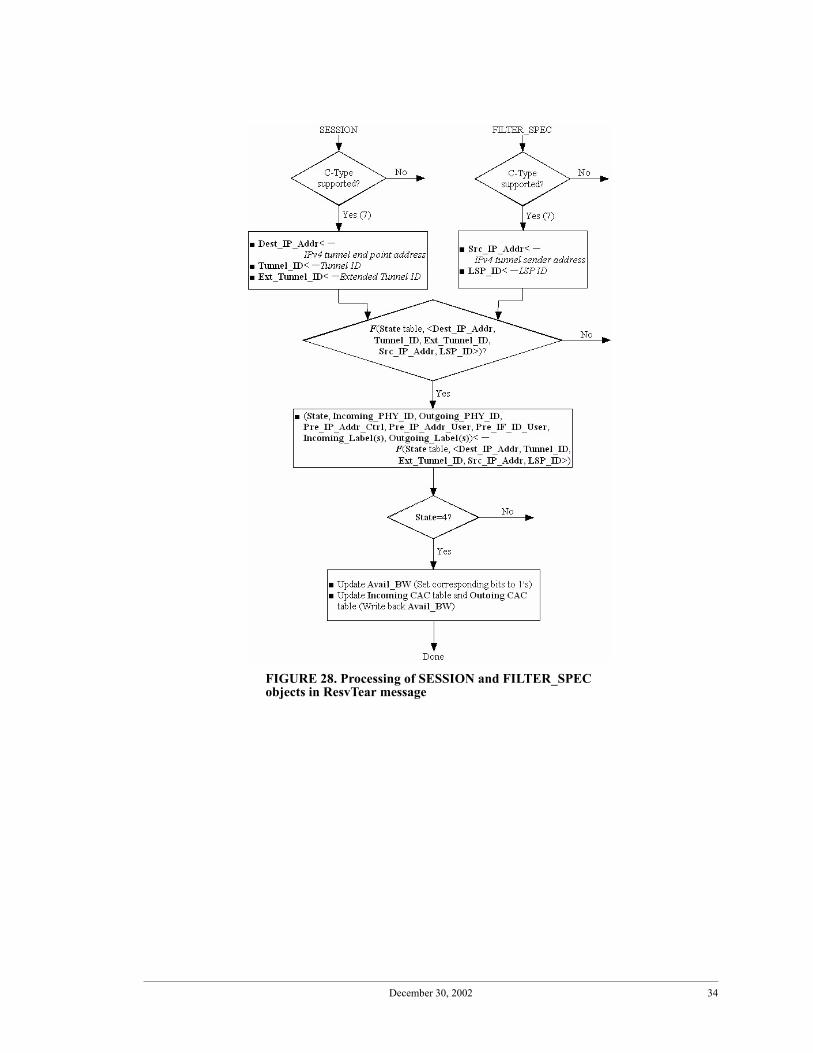
FIGURE 28. Processing of SESSION and FILTER_SPEC objects in ResvTear message

December 30, 2002 35
References[1] H. Wang, M. Veeraraghavan, T. Li, “Specification of a Subset of RSVP-TE for Hardware Implemen-
tation,” Nov. 2002, http://eeweb1.poly.edu/networks/papers/rsvp-subset.pdf.[2] H.Wang, M.Veeraraghavan and R. Karri, “A hardware implementation of a signaling protocol,” ac-
cepted to Opticomm 2002, July 29-Aug. 2, 2002, Boston, MA.
FIGURE 29. At the end of ResvTear message processing
FIGURE 30. Assemble new ResvTear message

December 30, 2002 36
[3] E. Mannie, “GMPLS Architecture,” IETF Internet Draft, draft-many-gmpls-architecture-00.txt, Mar.2001.
[4] E. Mannie (editor) et al., “GMPLS Extensions for SONET and SDH Control, IETF Internet Draft,draft-ietf-ccamp-gmpls-sonet-sdh-01.txt, June 2001.
[5] P. Ashwood-Smith, et al. “Generalized MPLS - Signaling Functional Description,” IETF InternetDraft draft-ietf-mpls-generalized-signaling-05.txt, July 2001.
[6] P. Ashwood-Smith, et al, “Generalized MPLS Signaling - CR-LDP Extensions,” IETF Internet Draft,draft-ietf-mpls-generalized-cr-ldp-03.txt, May 2001.
[7] P. Ashwood-Smith, et al. “Generalized MPLS - RSVP-TE Extensions,” IETF Internet Draft, draft-ietf-mpls-generalized-rsvp-te-08.txt, August 2002.

December 30, 2002 37
5. Appendix5.1 Comparison of RSVP-TE and OCSP
In this section, we compare RSVP-TE to OCSP (Optical Circuit-switched SignalingProtocol) that we designed for SONET networks [2], and clarify the definition of certainterms.
TABLE 16. Mapping parameters of OCSP to RSVP fields in objects
Message Optical Circuit Signaling Protocol (OCSP) RSVP
Setup and Setup-suc-cess (OCSP); Path and Resv (RSVP)
Connection reference Tunnel ID /Ext. Tunnel ID and IPv4 tunnel end point address within SESSION object/LSP ID and IPv4 tunnel sender address within SENDER_TEMPLATE/FILTER_SPEC object
Destination IP address IPv4 tunnel end point address within the SES-SION object
Source IP address IPv4 tunnel sender address within SENDER_TEMPLATE/FILTER_SPEC object
Previous node’s IP address IPv4 Next/Previous Hop address within RSVP_HOP object
Bandwidth Traffic parameters within SENDER_TSPEC/FLOWSPEC
Interface number Interface ID in IF_ID RSVP_HOP object (3209)Timeslot number Generalized LABEL objectTTL RECORD_ROUTE object is used for loop detec-
tion (like PATH_VECTOR in LDP). This is optional, which means it will be handled in soft-ware. Therefore, we have no easy way of detect-ing loops on the fast path. RSVP was originally designed to be added to an IP router and the rout-ing table used for IP forwarding is the same rout-ing table used for flow setup; but we could be running a GMPLS RSVP-TE engine in a SONET XC which does not have a collocated IP router. In this case, there is no provision to detect loops during call setup.
Checksum RSVP_ChecksumNo corresponding parameter TIME_VALUES object
Release and Release-Confirm (OCSP); PathTear and Res-vTear (RSVP)
Cause No corresponding parameterConnection reference (Prev) Tunnel ID /Ext. Tunnel ID and IPv4 tunnel end
point address within SESSION object & LSP ID and IPv4 tunnel sender address within SENDER_TEMPLATE/FILTER_SPEC object
Connection reference (own)
No corresponding parameters RSVP_HOP in both and STYLE, FLOWSPEC in ResvTear

December 30, 2002 38
5.2 Explanation for connection reference
The signaling engine at a switch needs to be able to identify a connection when firstcreated in order to associate subsequent signaling messages arriving at the switch withconnections. This is typically called a “connection reference.” Connection references canbe local or global. Local numbers are unique to a switch, while global connection refer-ences identify a connection globally across all switches. Usage of local connection refer-ences leads to performance-friendly implementations because the state table, which isindexed on the connection reference, is easier to search than if connection references areglobal. Nevertheless, RSVP-TE chose a global connection reference.
The SESSION object in RSVP carries destination port and as explained in Section 1.1of RFC2205, the destination port provides for further multiplexing (along with IP protocolID). In other words, a host can have many connections set up to a destination IP address.The actual destination is a process inside the end host. In RFC 3209, the Tunnel ID fieldreplaces the Destination Port of RFC 2205 in the SESSION object. This means that theTunnel ID is a field used for further demultiplexing at the destination. Does this mean itcan be ignored in the transit switches? No, because it is used to identify the connection. Itforms a connection reference number in conjunction with LSP ID in the sender templateobject along with source and destination IP addresses.
The SENDER_TEMPLATE object identifies the source of the connection. It not onlycarries the IP address of the sender but also the source port number in RFC 2205. In RFC3209, the source port was replaced by an LSP ID. The question is what is the differencebetween an LSP and a tunnel?
RFC 3031 states the difference between an LSP and an LSP tunnel. An LSP tunnel islike an ATM VPC with another LSP passing through it such as an ATM VCC. In otherwords, using label stacking, you can create an LSP tunnel, which is itself an LSP, butwhen this LSP is on the end-to-end path of another LSP, then it becomes an LSP tunnel.The general definition of LSP tunnel given in 3209 that it is “an LSP which is used to tun-nel below normal IP routing and/or filtering mechanism” suggests that even a one-levelLSP between two IP routers is an LSP tunnel. Then strictly speaking, the only situationunder which an LSP is not an LSP tunnel is if the LSP carries non-IP traffic! For example,in our end-to-end Ethernet/EoS circuits if we run ST (Scheduled Transfer) protocol over aSONET LSP, then the LSP is not an LSP tunnel.
We clarify a few more terms below:1. What is a traffic trunk? This is defined in RFC 2702. “A traffic trunk is an aggrega-
tion of traffic flows of the same class which are placed inside an LSP.” Traffic trunks arecompared to ATM virtual circuits in this RFC.
3. What is a Traffic engineered LSP? We could not find this term in any RFC. Wecoined it to be an LSP that has allocated resources to meet certain QoS requirements. Onpage 7 of 3209 there is a statement that LSP tunnels can be established with or withoutQoS requirements. An LSP or a LSP tunnel can indeed be established without the CAC/resource reservation phase. The phrase “CR LSP” is used instead of “traffic engineeredLSP” in the CR-LDP specification. It says “constraint based routing” is more than justsource routing (explicit routing). The latter is a subset of the more general concept of con-

December 30, 2002 39
straint based routing. The set of QoS requirements for an LSP is viewed as a constrainttaken into consideration when setting up the LSP.
4. Traffic Engineered Tunnel (TE Tunnel): This is defined on page 6 of 3209 as “A setof one or more LSP tunnels which carries a traffic trunk.” Can we assume that to carry a“traffic trunk” through an LSP, the LSP should be traffic engineered? If so, the TE Tunnelis a set of one or more TE LSP tunnels.
RFC 3209, page 6, describes “a traffic trunk being spread over multiple paths.” It statesthat to identify and associate LSP tunnels used within a TE tunnel, we need the tunnel ID,which is carried in the SESSION object and the LSPID, which is carried inSENDER_TEMPLATE and FILTER_SPEC. This means that to set filters at the LSRsboth these IDs need to be associated with labels. Unlike in RSVP (2205) where the sourceport specified in the FILTER_SPEC is used to directly filter out packets that need a spe-cific type of treatment (QoS), here the FILTER_SPEC carries an LSP ID but the packetsthemselves carry labels. This is because labels change at each switch, whereas source portdoes not. Hence we need to use some other ID during call setup, and this is LSP ID. There-fore the combination of LSP ID and Tunnel ID along with source IP and destination IPaddress is indeed the connection reference. It is a global connection reference! Clearly, inchoosing global connection references instead of local connection reference, attention wasnot paid to performance aspects.
Also, the reason for having both a tunnel ID and and an LSP ID is that there is no con-cept of grouping virtual circuits set up at the IP level with RSVP. This feature can be usedto set up a virtual concatenated SONET signal with individual signals routed on differentpaths.
5.3 Explanation for Style
Depending on the style of resource reservation, there is a correlation betweenFILTER_SPEC and FLOWSPEC. FLOWSPEC specifies the QoS requirements for thatreceiver. FILTER_SPEC indicates whether multiple senders can send on to the same flow(shared explicit reserved resources), data from all senders are shared on the same flow res-ervation (shared wildcard) or whether each sender has a unique reservation (Fixed Filter -FF) reservation style. The FILTER_SPEC allows routers to filter out appropriate packetsand give them the reserved resources. In FF style, one FLOWSPEC is associated witheach FILTER_SPEC. Therefore FILTER_SPEC carries not only the source address butalso the source port. Remembering that in RSVP Path messages are advertisements fortraffic being multicast (which then allows receivers to ask for reservations for a leg of the
If an end host asks for 7VT1.5 to carry an Ethernetsignal, each VT1.5 could be carried on a separatepath. All have the same tunnel ID, but different
LSP tunnel
end hostor IProuter
LSP1
LSP2
LSP1+LSP2 = TE tunnel
FIGURE 31. LSP tunnels, LSPs, TE tunnels
end hostor IProuter
LSP IDs.

December 30, 2002 40
multicast session toward them from the main tree), the Path message carrySENDER_TSPEC - traffic characteristics of the data being sent by specific senders. Inaddition, SENDER_TEMPLATE carries a source port to indicate which application run-ning on this UDP port is generating multicast traffic with the SENDER_TSPEC character-istics.

December 30, 2002 1
List of FiguresFIGURE 1. Prefixes and suffixes used in this document ........................................................................4FIGURE 2. Network used for illustrative examples; shows that (i) switches can be connected via
many user-plane interfaces (ii) logical links can be provisioned between non-adjacent switches (iii) a signaling engine may have many signaling links leading to the connectionless signaling network (IP network)7
FIGURE 3. Signaling message flow for setting up a unidirectional circuit; SW1 is upstream relative to SW2, and SW2 is upstream relative to SW3 because of the direction of the circuit; the data sender initiates circuit setup7
FIGURE 4. Example of Avail_BW.........................................................................................................9FIGURE 5. State transition diagram .....................................................................................................12FIGURE 6. Processing of common header ...........................................................................................16FIGURE 7. Processing of Path message ...............................................................................................17FIGURE 8. SESSION and SENDER_TEMPLATE objects in Path message ......................................18FIGURE 9. Processing of RSVP_HOP object in Path message ...........................................................19FIGURE 10. Processing of TIME_VALUES object in any message......................................................20FIGURE 11. Processing of SENDER_TSPEC object in Path message..................................................20FIGURE 12. Processing of LABEL_REQUEST object in Path message ..............................................21FIGURE 13. At the end of Path message processing..............................................................................22FIGURE 14. Assemble new Path message .............................................................................................23FIGURE 15. Processing of Resv message ..............................................................................................24FIGURE 16. Processing of SESSION and FILTER_SPEC objects in Resv message ............................25FIGURE 17. Processing of RSVP_HOP in Resv message .....................................................................26FIGURE 18. Processing of STYLE object in any message ....................................................................27FIGURE 19. Processing of FLOWSPEC object in Resv message .........................................................27FIGURE 20. Processing of LABEL object in Resv message .................................................................28FIGURE 21. At the end of Resv message processing.............................................................................29FIGURE 22. Assemble new Resv message ............................................................................................29FIGURE 23. Processing of PathTear message ........................................................................................30FIGURE 24. Processing of SESSION and SENDER_TEMPLATE objects in PathTear message.........31FIGURE 25. At the end of PathTear message processing.......................................................................32FIGURE 26. Assemble new PathTear message ......................................................................................32FIGURE 27. Processing of ResvTear message .......................................................................................33FIGURE 28. Processing of SESSION and FILTER_SPEC objects in ResvTear message .....................34FIGURE 29. At the end of ResvTear message processing......................................................................35FIGURE 30. Assemble new ResvTear message .....................................................................................35FIGURE 31. LSP tunnels, LSPs, TE tunnels ..........................................................................................39

December 30, 2002 1
List of TablesTABLE 1. Registers extracted from messages ......................................................................................5TABLE 2. Initialization registers ..........................................................................................................6TABLE 3. Routing table........................................................................................................................8TABLE 4. Incoming Connectivity table................................................................................................8TABLE 5. Incoming Connectivity table at switch II in Figure 2 ..........................................................8TABLE 6. Incoming CAC table ............................................................................................................9TABLE 7. Incoming CAC table at switch II in Figure 2.......................................................................9TABLE 8. Outgoing Connectivity table ..............................................................................................10TABLE 9. Outgoing Connectivity table for switch I in Figure 2........................................................10TABLE 10. Outgoing CAC table ..........................................................................................................10TABLE 11. Outgoing CAC table for switch I in Figure 2 ....................................................................10TABLE 12. Data/Control Mapping table ..............................................................................................11TABLE 13. State table...........................................................................................................................11TABLE 14. An example state table entry at switch II for the connection shown in Figure 2...............13TABLE 15. Updating State table after processing a Path message .......................................................22TABLE 16. Mapping parameters of OCSP to RSVP fields in objects..................................................37


![Internet-Draft draft-ali-pce-remote-initiated-gmpls-lsp-02 · - GMPLS also specifics support for asymmetric bandwidth requests [RFC6387]. - GMPLS extends the addressing to include](https://static.fdocuments.net/doc/165x107/5b1e55d57f8b9a116d8b6ebe/internet-draft-draft-ali-pce-remote-initiated-gmpls-lsp-02-gmpls-also-specifics.jpg)