Detai ling - Oregon State University
65
CHAPTER 11 Detai l ing Simply put, if detailing doesn’t work, then you’ll use the Autodesk ® Revit ® Architecture software only as a schematic design application. It’s imperative that you can detail efficiently in Revit. When firms fail in their attempt to use Revit, it’s because of detailing. In fact, many who have bought this book may jump straight to this chapter. Why is that? It’s because many people (including me) buy into the concept of really cool 3D perspectives and one-button modeling. This chapter covers the following topics: ▶ Working with line weights ▶ Draf ting on top of the detail ▶ Adding notes ▶ Creating blank draf ting views Working with Line Weights When you understand Revit, you find out immediately that the real hurdle in getting it to work lies in the detailing. Sure, you can cut sections and create callouts, but how do you add that fine level of detailing needed to produce a set of documents that you’re willing to stamp and sign? This chapter addresses the issues surrounding detailing. The first thing that comes to mind when dealing with CAD standards is line weights, right? In AutoCAD ® it’s layers, in MicroStation it’s levels, but on paper, it’s line weights that control 75 percent of a company’s standards. As you’ll learn in this chapter, Revit can be a good 2D drafting application as well. As you learn how to control line weights in the 3D elements, you can also control line weights, well, line by line. N OTE Metric users should not t y pe in mm or other metric abbreviations when enterin g amounts su gg ested in the exercises. Revit will not accept such abbreviations. Simpl y enter the number provided within the parentheses.
Transcript of Detai ling - Oregon State University

CHAPTER 11
Detailing Simply put, if detailing doesn’t work, then you’ll use the Autodesk ® Revit® Architecture software only as a schematic design application. It’s imperative that you can detail effi ciently in Revit. When fi rms fail in their attempt touse Revit, it’s because of detailing. In fact, many who have bought this book may jump straight to this chapter. Why is that? It’s because many people(including me) buy into the concept of really cool 3D perspectives and one-button modeling.
This chapter covers the following topics:
▶ Working with line weights
▶ Drafting on top of the detail
▶ Adding notes
▶ Creating blank drafting views
Working with Line Weights When you understand Revit, you fi nd out immediately that the real hurdle in getting it to work lies in the detailing. Sure, you can cut sections and createcallouts, but how do you add that fi ne level of detailing needed to produce a set of documents that you’re willing to stamp and sign? This chapteraddresses the issues surrounding detailing.
The fi rst thing that comes to mind when dealing with CAD standards is line weights, right? In AutoCAD® it’s layers, in MicroStation it’s levels, buton paper, it’s line weights that control 75 percent of a company’s standards. As you’ll learn in this chapter, Revit can be a good 2D drafting application aswell. As you learn how to control line weights in the 3D elements, you canalso control line weights, well, line by line.
N O T E Metric users should not type in mm or other metric abbreviationswhen entering amounts suggested in the exercises. Revit will not accept such abbreviations. Simply enter the number provided within the parentheses.

5 3 0 C h a p t e r 11 • D e t a i l i n g
To begin, open the fi le you’ve been using to follow along. If you didn’tcomplete Bonus Chapter 1 , “Advanced Wall Topics,” go to the book’s web page atwww.sybex.com/go/revit2017ner . From there, you can browse to the Chapter 11 folder and fi nd the fi le called NER-11.rvt .
The objective of this procedure is to format the line weights and to see whereand how they’re read by Revit:
1. In the Project Browser, open the building section called Roof Taper Section. Zoom into the wall at the left.
2. Click off Thin Lines and notice that the perimeters of the walls and the roof are extremely heavy in contrast to the fi ner lines that divide the submaterials. This is what you’ll change. On the Settings panel of the Manage tab, click the Object Styles button at the left on the Ribbon.
3. In the Object Styles dialog box is a list of every object categoryavailable in Revit. The fi rst items you want to change are the roofs.In the Category column, scroll down until you see Roofs, as shownin Figure 11.1 .
F I G U R E 1 1 . 1 : Changing the object line weights
Glancing up at the headers that describe the columns, you seethe Line Weight column. This column is divided into two sections: Projection and Cut. The Projection column controls the line weights of

W o r k i n g w i t h L i n e W e i g h t s 5 3 1
objects as they’re viewed in plan or elevation. The Cut column controls the line weights as they’re shown in section. So, to reiterate, projection means plan and elevation, and cut means section. Your objective is to modify the line weight for both the cut and the projection of the roof.
4. In the Roofs row, change the Cut value to 3 (see Figure 11.1 ).
5. Click the plus sign next to Roofs to expand the category.
6. All the subelements are shown, and you can control the line weightsaccordingly. Change the Cut value of Fascias to 5 .
7. Change the Cut value for Gutters to 5 .
8. Change the Cut value for Roof Soffi ts to 5 (again, see Figure 11.1 ).
9. Find Floors, and change Cut Line Weight to 3 .
10. Find Walls, and change Cut Line Weight to 3 .
11. Click OK, and you’ll see the change to your outline (see Figure 11.2 ).
F I G U R E 1 1 . 2 : Your section’s outline should begin looking a lot better.
mplate Time! It’s Tem Many of the procedures covered in the first section of this chapter lend themselves well to the topic of standards and templates. You need to change the line weights of objects in a Revit template.

5 3 2 C h a p t e r 11 • D e t a i l i n g
Drafting on Top of the Detail As mentioned, Revit provides a good number of 2D details that you can insert at any time. When Revit doesn’t have the component you need, you can alwayscreate one. It isn’t that hard to do.
In this section, you’ll physically create a detail. The procedures you’ll apply consist of adding detail components, linework, and fi lled regions and doing some good old-fashioned drafting!
Using Predefined Detail Components The fi rst procedure focuses on inserting predefi ned detail components. The great thing about this is that you’ll do nothing you haven’t done repeatedlythroughout this book—it’s just a matter of fi nding the right button to get started.
1. Make sure you’re still in the detail called Roof Taper Section.
2. On the Detail panel of the Annotate tab, click Component ➢ DetailComponent, and then click the Load Family.
3. Browse to the Detail Items directory. (It’s located in the USImperial Library directory.)
4. Open the Div 01-General folder.
5. Click the fi le called Break Line.rfa .
6. Click Open.
7. In the Type Selector of the Properties dialog box, be sure Break Line is selected, as shown in Figure 11.3 .
8. Press the spacebar twice. (This fl ips the break line into the correctorientation.)
9. Pick a point similar to the one shown in Figure 11.3 .
The next step is simply to start drafting. As mentioned earlier, you’re onlygoing to get so far with 3D modeling before you have to take matters into your own hands and draft. You can approach this in Revit by taking the parts of the detail you want to keep and hiding the rest. After you hide portions of the detail, it’s time to begin adding your own ingredients, such as detail components andlines.

D r a f t i n g o n To p o f t h e D e t a i l 5 3 3
F I G U R E 1 1 . 3 : Placing the break line and flipping the component
lippin’ Break Line Is Backward! This Fl If you forgot to flip the break line as you were inserting it and it’s masking the wrong region, that’s OK. Press Esc, and then select the break line. Now you can press the spacebar twice to flip the break line, as shown here:

5 3 4 C h a p t e r 11 • D e t a i l i n g
Masking Regions To let you hide portions of the detail, Revit has added a nice feature called amasking region . Instead of wrestling with items over which you ultimately have little or no control, you can hide these items to make way for your detailing.
To learn how to apply a masking region, follow these steps:
1. Make sure you’re still in the detail called Roof Taper Section.
2. On the Draw panel of the Annotate tab, click Region ➢ MaskingRegion, as shown in Figure 11.4 .
F I G U R E 1 1 . 4 : Creating a masking region
3. The Line Style panel offers some choices in the subcategory. Choose <Invisible Lines>, as shown in Figure 11.5 .
F I G U R E 1 1 . 5 : Click the Rectangle button on the Draw panel, and place amasking region as shown.

D r a f t i n g o n To p o f t h e D e t a i l 5 3 5
N O T E By selec ting <Invisible Lines>, you ensure that the perimeter of themasking region won’t be visible when you exit Sketch Mode.
F I G U R E 1 1 . 6 : Click the Bring To Front button on the Modify | Detail Items tabafter selecting the break line.
4. Again on the Draw panel, click the Rectangle button.
5. Draw a rectangle at the approximate points shown in Figure 11.5 .
6. Click the Finish Edit Mode button on the Mode panel.
The area is now masked. The problem is, though, that some areas, such as thebreak, may be a little too masked. The next procedure walks through changingthe display order of a detail’s objects:
1. If the break line is behind the masking region, select the break line,as shown in Figure 11.6 .

5 3 6 C h a p t e r 11 • D e t a i l i n g
2. On the Modify | Detail Items tab, click the Bring To Front button (see Figure 11.6 ).
Your detail should now look like Figure 11.7 .
F I G U R E 1 1 . 7 : The detail with the completed masking region
The next step is to add a brick face. Yes, Revit showed the brick before you masked it, but you need to show coursing, as well as how the façade is tied backto the wall. To do this, you’ll use a function called a repeating detail .l
Repeating Details Revit has a technique that allows you to add a detail component as a group. Youdo this by basically drawing a line; Revit then adds the detail in an array basedon the points you pick.
To learn how to add a repeating detail, follow this procedure:
1. On the Detail panel of the Annotate tab, select Component ➢Repeating Detail Component, as shown in Figure 11.8 .

D r a f t i n g o n To p o f t h e D e t a i l 5 3 7
2. In the Properties dialog box, choose Repeating Detail : Brick from the Type Selector.
3. Pick the point labeled 1 in Figure 11.9 .
F I G U R E 1 1 . 8 : Select Component ➢ Repeating Detail Component.
F I G U R E 1 1 . 9 : Adding the repeating detail based on the points shown
T I P Picking that point will be a little harder now that it ’s not there! The objec-tive is to draw an actual façade based on the existing points where the Revit-generated brick once resided. When you hover your mouse over where the brick was previously, the masked detail appears. When it does, you’ll see the point you need to pick.

5 3 8 C h a p t e r 11 • D e t a i l i n g
4. After you pick the fi rst point, move your cursor down the view.
5. The brick is facing the wrong side. Press the spacebar to fl ip the brick into the wall (see Figure 11.9 ).
6. Pick the endpoint 8 (203 mm) down, as shown in Figure 11.9 , so that three copies of the brick section are placed.
Your detail should look like Figure 11.10 .
F I G U R E 1 1 . 1 0 : The first repeating detail
Let’s keep going with the repeating detail. The problem you’re facing is that you need to deal with the soldier course in the exterior wall. You can add that in a moment. Right now, complete the brick down past the break line.
If you feel as though you’re getting the hang of adding the repeating brick detail, go ahead and add the second repeating detail. If you would like someinstruction, follow these steps:
1. Click the Component ➢ Repeating Detail Component button on the Detail panel on the Annotate tab.
2. Pick point 1, as shown in Figure 11.11 .

D r a f t i n g o n To p o f t h e D e t a i l 5 3 9
3. Press the spacebar.
4. Pull the cursor straight down, and pick point 2 (see Figure 11.11 ). Make sure you pick the second point well past the break line, or thebrick will stop short.
5. Press Esc twice. Look at Figure 11.12 . Does your detail look the same?
F I G U R E 1 1 . 1 1 : Picking two points
◀
Remember, you canadd a second repeatingbrick detail by right-clicking the fi rst one you added and select-ing Create Similar.
F I G U R E 1 1 . 1 2 : The bricks are being placed.

5 4 0 C h a p t e r 11 • D e t a i l i n g
6. If the repeating detail is obscuring the break line, select the break line.
7. On the Arrange panel, click the Bring To Front button. The repeatingdetail is now behind the break line.
The next step is to add the soldier course. You’ll do this the same way youadded the break line. In this respect, Revit offers a good library broken downinto the CSI format.
To add the soldier course, follow these steps:
1. On the Detail panel on the Annotate tab, click the Component ➢Detail Component button.
2. In the Type Selector in the Properties dialog box, select Brick Standard : Soldier & Plan.
3. Press the spacebar until it’s fl ipped as shown in Figure 11.13 , and place the new detail component into the model as shown.
F I G U R E 1 1 . 1 3 : Placing the new detail component
T I P If you haven’t noticed, when you click the Component ➢ Repeating
Detail Component button, you always go to the Families / DetailItems directory in the Project Browser. This may go without saying, but ittook a few months for me to understand this simple concept.
D r a f t i n g o n To p o f t h e D e t a i l 5 4 1
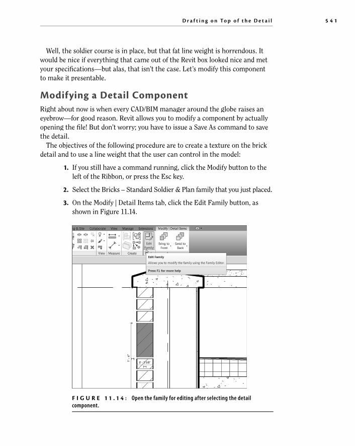
Well, the soldier course is in place, but that fat line weight is horrendous. It would be nice if everything that came out of the Revit box looked nice and met your specifi cations—but alas, that isn’t the case. Let’s modify this componentto make it presentable.
Modifying a Detail Component Right about now is when every CAD/BIM manager around the globe raises an eyebrow—for good reason. Revit allows you to modify a component by actuallyopening the fi le! But don’t worry; you have to issue a Save As command to save the detail.
The objectives of the following procedure are to create a texture on the brick detail and to use a line weight that the user can control in the model:
1. If you still have a command running, click the Modify button to the left of the Ribbon, or press the Esc key.
2. Select the Bricks – Standard Soldier & Plan family that you just placed.
3. On the Modify | Detail Items tab, click the Edit Family button, asshown in Figure 11.14 .
F I G U R E 1 1 . 1 4 : Open the family for editing after selecting the detailcomponent.

5 4 2 C h a p t e r 11 • D e t a i l i n g
4. The next dialog box may ask you if you want to open this fi le to editit. Click Yes if you get that message.
The detail component family is now open. It’s time to operate, Doctor. Thenext set of procedures will focus on modifying the linework of the brick and add-ing what is called a fi lled region .
Modifying Filled Regions A fi lled region is similar to a masking region in that you apply both in the samemanner. A fi lled region, however, contains a hatch pattern that is visible when the region is completed. This is how you hatch in Revit. It takes the place of the conventional hatch command found in AutoCAD and MicroStation.
The goal of the next procedure is to modify the fi lled region that makes up the brick. You’ll also use the region’s outline to defi ne the perimeter and the textureof the brick.
1. Click the Revit Application button, and select Save As ➢ Family.
2. Call the new family Brick – Soldier . r
3. Click the Family Types button, as shown in Figure 11.15 .
4. In the Name menu, make sure Running Section is selected.
5. Click the Delete button at the right in the dialog box.
F I G U R E 1 1 . 1 5 : Cleaning out the extra types

D r a f t i n g o n To p o f t h e D e t a i l 5 4 3
6. Select Rowlock from the list, and delete that type as well.
7. Click OK.
8. Select the line that is hovering over the top of the brick, and mirror itto the bottom so you have a line above and a line below the brick, as shown in Figure 11.16 .
F I G U R E 1 1 . 1 6 : Editing the boundary of the filled region
9. Select one of the heavy lines that form the outline of the brick (see Figure 11.16 ). Revit indicates that this is a fi lled region, as revealed inthe tooltip that appears when you hover your pointer over one of theboundaries.
10. On the Mode panel of the Modify | Detail Items tab, click the Edit Boundary button (see Figure 11.16 ).

5 4 4 C h a p t e r 11 • D e t a i l i n g
11. Delete the two thick, vertical lines.
N O T E As you may notice, changing a line’s property is almost the same as inAutoCAD. You select the line and then change its line type in the Type Selector.
12. On the Draw panel, select the Line button, as shown in Figure 11.17 .
F I G U R E 1 1 . 1 7 : Adding a texture to the brick family
13. In the Line Style panel that appears, select Detail Items.
14. Draw a series of jagged lines on the right and left of the brick, asshown in Figure 11.17 .
15. After you fi nish sketching the texture, click Edit Type.

D r a f t i n g o n To p o f t h e D e t a i l 5 4 5
Should You Save This? Where When you click the Save icon, Revit doesn’t save over the original file. You’re forced to perform a Save As. You have three choices.
▶ If the file isn’t write-protected and you have administrative access to the original folder, you can save over the original file. (Do I need to mention that you had better make sure this is what you want to do?)
▶ Save the file as a different file, either in the same directory or somewhere else.
▶ Don’t save the file at all, and load it into your project. Revit will still update the project with the changes even if you don’t save the family file.
You can even close out of the family file and not save any changes. Your model will still hold the changes. If you choose to edit the file at a later date, you can select thefamily in the model and click Edit Family. Revit will open a copy of the modified family.
16. Change the background from Opaque to Transparent, as shown inFigure 11.18 .
F I G U R E 1 1 . 1 8 : Changing the background to Transparent

5 4 6 C h a p t e r 11 • D e t a i l i n g
17. Click OK.
18. Click Finish Edit Mode. Your brick should resemble Figure 11.19 .
F I G U R E 1 1 . 1 9 : The finished soldier
Next, you’ll add a mortar joint to the bottom of the brick. You simply adddrafting lines.
1. On the Create tab, click the Line button.
2. On the Draw panel, click the Start-End-Radius Arc button.
3. Draw two arcs to the left and right of the top of the brick, as shown in Figure 11.20 .
N O T E By putting all the lines on the Detail Items line type, you tell Revit thatyou don’t want to specify a line weight here. Rather, Revit should let you specify the line weight by changing the Detail Items in the Object Properties dialog box after you load the detail back into the model.

D r a f t i n g o n To p o f t h e D e t a i l 5 4 7
F I G U R E 1 1 . 2 0 : Adding the mortar joint
The next step is to add shading underneath the brick pattern. To do this, you’ll create an entirely new fi lled region and add it to the brick by tracing over the existing fi lled region.
1. On the Detail panel of the Create tab, click the Filled Region button, as shown in Figure 11.21 .
F I G U R E 1 1 . 2 1 : Click the Filled Region button on the Detail panel.
2. In the Properties dialog box, click the Edit Type button, and makesure Type is Solid Fill – Black, as shown in Figure 11.22 .
F I G U R E 1 1 . 2 2 : Changing the region to Solid Fill – Black

5 4 8 C h a p t e r 11 • D e t a i l i n g
3. Click Duplicate.
4. Call the new region Light Shade .
5. Click OK.
6. In the Fill Pattern row, click into the Solid Fill [Drafting] fi eld. Click the […] button in the right corner.
7. You can select any hatch pattern you want. Make sure Solid Fill is selected, as shown in Figure 11.23 , and click OK.
F I G U R E 1 1 . 2 3 : Select the Solid Fill pattern, and click OK.
8. In the Color row is a button labeled Black. It includes a little black box icon. Pick the black box.
9. In the Color dialog box, click the gray tile, as shown in Figure 11.24 . (The color is actually RGB 192-192-192.)
F I G U R E 1 1 . 2 4 : Selecting the gray color (RGB 192-192-192)

D r a f t i n g o n To p o f t h e D e t a i l 5 4 9
10. Click OK twice.
11. On the Draw panel, click the Pick Lines button, as shown inFigure 11.25 .
F I G U R E 1 1 . 2 5 : Press Tab to select the chain of lines, as shown here.
12. Hover your cursor over one of the jagged lines of the brick face, and press the Tab key. All the lines you’re trying to trace are highlighted.
13. Pick any one of the lines (see Figure 11.25 ). Revit draws the region based on these points.
◀
You may fi nd that noth-ing happens when you press Tab. If this is thecase, click any locationin the view. Revit needs to focus on the view. You can also hold down the wheel button onyour mouse to pan a little. This will also switch the focus from the Options bar to the view window.

5 5 0 C h a p t e r 11 • D e t a i l i n g
14. On the Mode panel, click Finish Edit Mode, and then press Esc. Yourbrick should look like Figure 11.26 .
F I G U R E 1 1 . 2 6 : The solid pattern covers the previous pattern. You’ll fix this ina moment.
15. When the fi lled region is in place, select it by clicking the boundary.
16. On the Arrange panel, click the Send To Back button, as shown inFigure 11.27 .
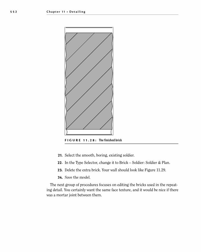
17. Press Esc. Your brick should now look like Figure 11.28 .
18. Click the Save icon.

D r a f t i n g o n To p o f t h e D e t a i l 5 5 1
F I G U R E 1 1 . 2 7 : Sending the light shade to the back
19. On the Family Editor panel on the Create tab, click the Load Into Project button.
20. Place the new soldier to the left of the wall.
5 5 2 C h a p t e r 11 • D e t a i l i n g
F I G U R E 1 1 . 2 8 : The finished brick
21. Select the smooth, boring, existing soldier.
22. In the Type Selector, change it to Brick – Soldier: Soldier & Plan.
23. Delete the extra brick. Your wall should look like Figure 11.29 .
24. Save the model.
The next group of procedures focuses on editing the bricks used in the repeat-ing detail. You certainly want the same face texture, and it would be nice if there was a mortar joint between them.

D r a f t i n g o n To p o f t h e D e t a i l 5 5 3
F I G U R E 1 1 . 2 9 : The new soldier brick in the model
Before you modify the bricks, let’s explore how a repeating detail is created. The objective of the next procedure is to discover how a repeating detail works and how you can create a new one.
1. Make sure you’re in the detail called Roof Taper Section.
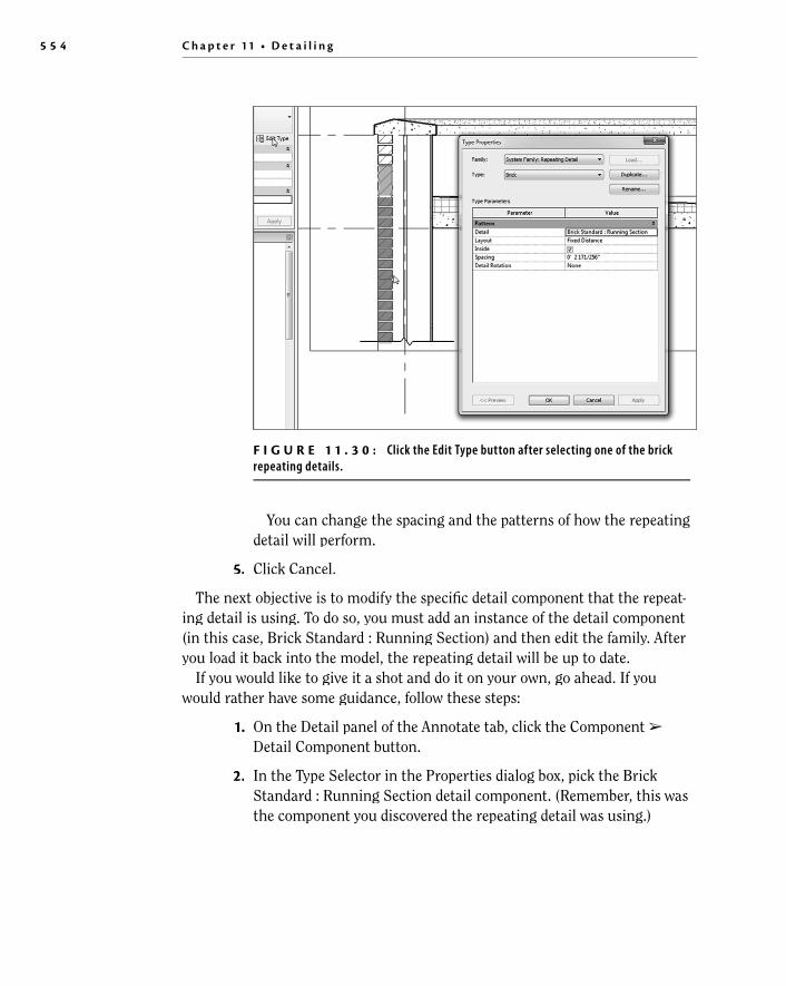
2. Select one of the repeating details, as shown in Figure 11.30 .
3. In the Properties dialog box, click Edit Type, as shown at the upper left in Figure 11.30 .
4. Click into the detail Value list. Every detail component listed in yourmodel is available. The detail component being used here is BrickStandard : Running Section.
5 5 4 C h a p t e r 11 • D e t a i l i n g
You can change the spacing and the patterns of how the repeating detail will perform.
5. Click Cancel.
The next objective is to modify the specifi c detail component that the repeat-ing detail is using. To do so, you must add an instance of the detail component(in this case, Brick Standard : Running Section) and then edit the family. After you load it back into the model, the repeating detail will be up to date.
If you would like to give it a shot and do it on your own, go ahead. If youwould rather have some guidance, follow these steps:
1. On the Detail panel of the Annotate tab, click the Component ➢Detail Component button.
2. In the Type Selector in the Properties dialog box, pick the BrickStandard : Running Section detail component. (Remember, this wasthe component you discovered the repeating detail was using.)
F I G U R E 1 1 . 3 0 : Click the Edit Type button after selecting one of the brickrepeating details.

D r a f t i n g o n To p o f t h e D e t a i l 5 5 5
3. Place the detail component off to the side of the wall, as shown in Figure 11.31 .
F I G U R E 1 1 . 3 1 : Place the Brick Standard : Running Section detail componentoff to the side. You’ll delete this occurrence of the component later.
4. Press Esc twice, or click Modify.
5. Select the Brick Standard : Running Section that you just inserted.
6. On the Mode panel, click the Edit Family button.
7. Select the fi lled region.
8. On the Mode panel, click Edit Boundary.
9. Delete the right and left thick lines.

5 5 6 C h a p t e r 11 • D e t a i l i n g
10. On the Draw panel, click the Line button.
11. In the Type Selector in the Properties dialog box, click Detail Items.
12. Draw the jagged lines on both sides, as shown in Figure 11.32 .
F I G U R E 1 1 . 3 2 : Draw the textured face while you’re in Edit Mode for the filled region. Draw the arcs for the mortar joint using lines.
13. Click Finish Edit Mode on the Mode panel.
14. On the Create tab, click the Line button.
15. On the Draw panel, click the Start-End-Radius Arc button.
16. On the Subcategory panel, be sure Detail Items is chosen from theType Selector list.
17. Draw an arc on both sides of the brick (see Figure 11.32 ).
18. When you’re fi nished, save the new brick as Brick Standard. You can also fi nd this brick on the book’s web page in Chapter 11 . It’s called Brick Standard.rfa .
19. On the Family Editor panel, click Load Into Project.
20. In the project, click to overwrite the family.
21. Delete the stray detail component you placed. (You were using it only for access to the family.)
Compare your detail to the detail in Figure 11.33 .

D r a f t i n g o n To p o f t h e D e t a i l 5 5 7
F I G U R E 1 1 . 3 3 : The brick actually looks like brick!
Next, you’ll anchor this façade back to the wall. You need to add two things: a structural relief angle above the soldier course and a brick tieback to a lower course. Follow these steps:
1. On the Annotate tab, click the Component ➢ Detail Componentbutton.
2. On the Mode panel, click the Load Family button.
3. Open the Detail items folder.
4. Select Div 05-Metals .
5. Select 051200-Structural Steel Framing .
6. Double-click the fi le AISC Angle Shapes-Section.rfa .
7. In the Type list, select L6×4×5/16 (152×102×8).
8. Click OK. You’ll have to use the spacebar and fl ip controls to rotate and fl ip the instance.
9. Place it into the model, as shown in Figure 11.34 .

5 5 8 C h a p t e r 11 • D e t a i l i n g
10. Press Esc twice, or click Modify.
Of course, the line weight is basically a blob, so you must modify the family inorder for it to look accurate. The next procedure is almost a review of what youhad to do to the bricks:
1. Select the angle.
2. On the Mode panel, click Edit Family.
3. In the Family Editor, select the fi lled region (the entire angle), and click Edit Boundary on the Mode panel.
4. Select all the lines that form the perimeter of the angle.
5. In the Type Selector in the Properties dialog box, select Detail Items.(You’re switching from Heavy Lines to Detail Items.)
6. On the Mode panel, click Finish Edit Mode.
7. On the Family Editor panel, click Load Into Project.
8. Click Overwrite The Existing Version.
F I G U R E 1 1 . 3 4 : Placing the L6×4×5/16 (152×102×8) angle

D r a f t i n g o n To p o f t h e D e t a i l 5 5 9
F I G U R E 1 1 . 3 5 : The angle in place and looking like an angle
9. Adjust the angle so it looks like Figure 11.35 .
The next step is to fi nd a fastener to anchor the angle back to the wall’s sub-strate. There is a problem, however. The type of bolt you need is a lag bolt thatis power-driven from the exterior into the wall. Revit doesn’t provide one out of the box. Luckily, the book you bought does! To fi nd the lag bolt provided with the book, go to the book’s web page, browse to the Chapter 11 folder, and fi nd thefi le A307 Lag_Bolt-Side.rfa . Then follow these steps:
1. To load the lag bolt into your model, select the Insert tab, and clickthe Load Family button. Browse to the directory where you put the A307 Lag_Bolt-Side.rfa fi le. Find the fi le, and click Open.
2. With the lag bolt loaded, click the Component ➢ Detail Componentbutton on the Annotate tab.
3. Select A307 Lag_Bolt-Side : 3⁄4 from the Type Selector.
4. Insert the lag bolt into the angle, as shown in Figure 11.36 .

5 6 0 C h a p t e r 11 • D e t a i l i n g
5. Press Esc twice.
Now you’ll add a corrugated wall tie to the brick below the soldier course.Because the brick is a pretty good distance away from the wall, you fi rst need to add some wood blocking to the model.
1. On the Insert tab, click the Load Family button.
2. Go to the Detail Items folder.
3. Select Div 06-Wood And Plastic .
4. Select 061100-Wood Framing .
5. Click the fi le Nominal Cut Lumber-Section.rfa .
6. Select the 2×6 (51×152) type, and click OK.
7. Select the Annotate tab, click the Component ➢ Detail Componentbutton, and place the 2×6 (51×152) into the wall, as shown in Figure 11.37 .
F I G U R E 1 1 . 3 6 : Inserting the lag bolt

D r a f t i n g o n To p o f t h e D e t a i l 5 6 1
8. Press Esc twice.
9. Select the blocking you just added, and right-click it.
10. Select Override Graphics In View ➢ By Element.
11. In the Projection Lines category, change the weight to 2 .
12. Click OK. Your blocking should look like Figure 11.37 .
The next step is to add the corrugated wall tie. You’ll do this in the same man-ner, except that it’s located in a different directory.
1. On the Insert tab, click the Load Family button.
2. Go to the Detail Items folder.
3. Select Div 04-Masonry. y
4. Select 040500-Common Work Results For Masonry.y
5. Select 040519-Masonry Anchorage And Reinforcing .
6. Select the fi le called Corrugated Wall Tie-Section.rfa .
F I G U R E 1 1 . 3 7 : Adding the wood blocking
5 6 2 C h a p t e r 11 • D e t a i l i n g
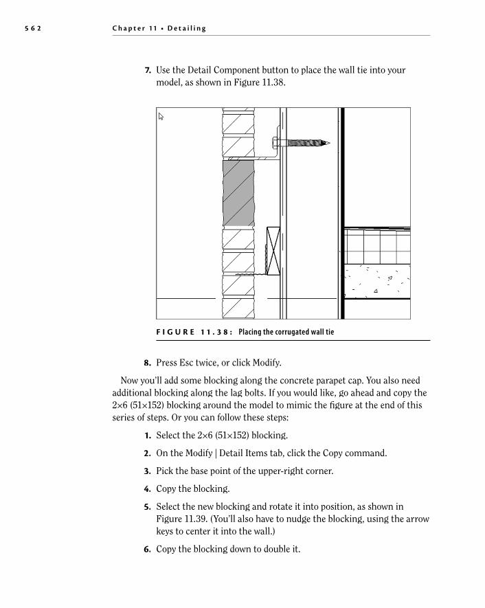
7. Use the Detail Component button to place the wall tie into yourmodel, as shown in Figure 11.38 .
F I G U R E 1 1 . 3 8 : Placing the corrugated wall tie
8. Press Esc twice, or click Modify.
Now you’ll add some blocking along the concrete parapet cap. You also needadditional blocking along the lag bolts. If you would like, go ahead and copy the 2×6 (51×152) blocking around the model to mimic the fi gure at the end of thisseries of steps. Or you can follow these steps:
1. Select the 2×6 (51×152) blocking.
2. On the Modify | Detail Items tab, click the Copy command.
3. Pick the base point of the upper-right corner.
4. Copy the blocking.
5. Select the new blocking and rotate it into position, as shown inFigure 11.39 . (You’ll also have to nudge the blocking, using the arrowkeys to center it into the wall.)
6. Copy the blocking down to double it.
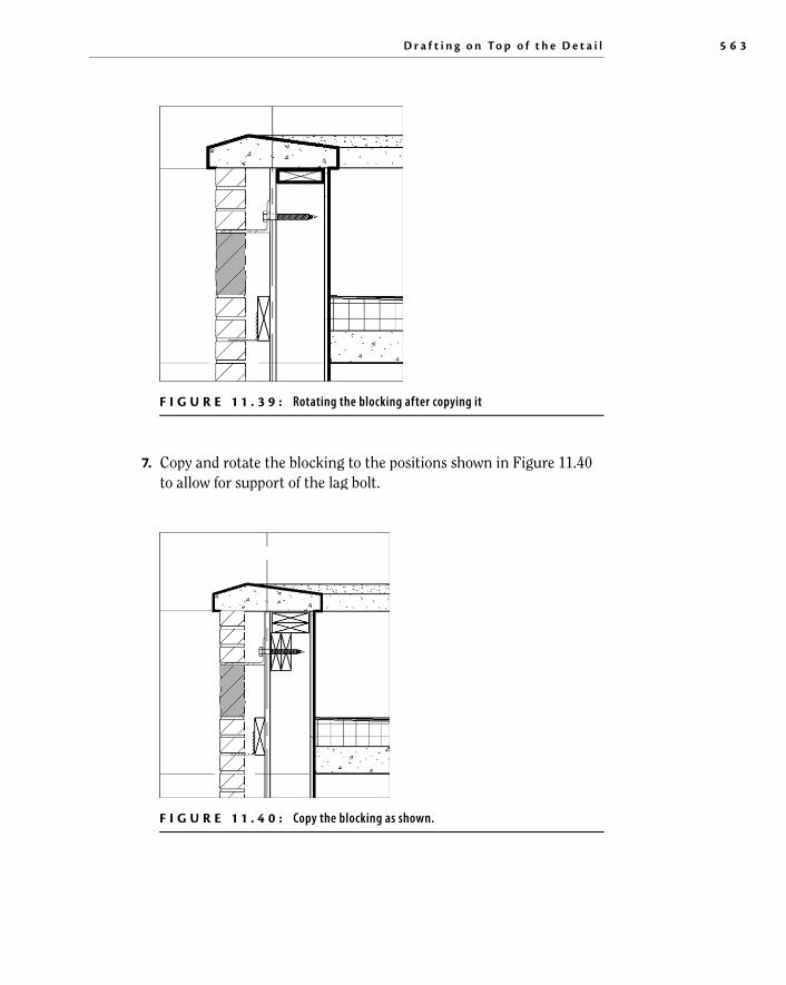
D r a f t i n g o n To p o f t h e D e t a i l 5 6 3
F I G U R E 1 1 . 3 9 : Rotating the blocking after copying it
7. Copy and rotate the blocking to the positions shown in Figure 11.40 to allow for support of the lag bolt.
F I G U R E 1 1 . 4 0 : Copy the blocking as shown.

5 6 4 C h a p t e r 11 • D e t a i l i n g
8. Select all the blocking that has the heavy line weight, right-click,and choose Override Graphics In View ➢ By Element. Change the Projection Line Weight value to 2 .
9. Compare your detail to Figure 11.40 .
When you’re drafting over a true section of your model, it’s always good to tryto use as much of the graphical information from the actual model as possible.For example, the 3⁄4 (16 mm) void you see the bolt going through is actually 3/4 (16 mm) plywood sheathing. For some reason, the default plywood material has its cut pattern set to None. Let’s fi x this:
1. Select the wall.
2. Click Edit Type.
3. Click the Edit button in the Structure row.
4. Click into the Material column in row 5. It’s the substrate row, andthe material is –Plywood, Sheathing.
5. When you click –Plywood, Sheathing, you see a tiny […] button.Click it.
6. On the Graphics tab, click into the Pattern fi eld in the CutPattern category, and change the pattern to Plywood, as shown in Figure 11.41 .
F I G U R E 1 1 . 4 1 : Show us your plywood!

D r a f t i n g o n To p o f t h e D e t a i l 5 6 5
7. Double-click the plywood pattern (see Figure 11.41 for the location of the cursor).
8. Click the Edit button.
9. Select the Align With Element drop-down for the Orientation In HostLayers fi eld.
10. Click OK three times to get back to the model.
Now that you have a good grasp of adding detail components, you need tolearn how to control the line weight so that the outlines of the bricks look alittle bolder.
If you remember, some of the detail components were modifi ed based on the line weight of the fi lled region perimeter. This thickness was changed fromHeavy Lines to Detail Items. You need to set Detail Items to a thickness you can live with.
1. On the Manage tab, click the Object Styles button.
2. Scroll down the list until you see Detail Items.
3. Change the Projection Line Weight to 2 , as shown in Figure 11.42 .
F I G U R E 1 1 . 4 2 : Changing the Detail Items Projection Line Weight to 2
4. Click OK. Your detail now has a bolder perimeter.
N O T E It ’s a great idea to plot this detail right now. Although Revit does a nice job of letting you see the contrasting line weights on the screen, it may be a differentstory at the plotter. Do yourself a favor, and make sure this is the line weight you want.
Another item left to explore in terms of adding detail to a view is the simple concept of drawing lines.

5 6 6 C h a p t e r 11 • D e t a i l i n g
Drawing Detail Lines As I mentioned, in Revit you can simply draw lines. You can get only so far with detail components, and then you need to pick up the pencil and add your lines.
The next set of procedures will focus on adding lines to your view. Then we’ll look deeper into how these lines are created and modifi ed.
1. In the Project Browser, make sure you’re in Sections (BuildingSections : Roof Taper Section).
2. On the Detail panel of the Annotate tab, click the Detail Line button.
3. In the Line Style menu, select Medium Lines, as shown in Figure 11.43 .
F I G U R E 1 1 . 4 3 : Select the Medium Lines choice in the Line Style menu.
4. On the Options bar, deselect the Chain option.
N O T E Does this seem familiar? If you’re used to the AutoC AD method of drafting, this is the same as starting the Line command and choosing the correct layer.
5. Draw a line, as shown in Figure 11.44 . Be sure to use your endpoint and perpendicular snaps.
6. With the Line command still running, click the Pick Lines icon on the Draw panel.
7. Change Offset to 1 1/2 (38 mm), as shown in Figure 11.45 .
8. Offset the line you just drew down 1 1/2 (38 mm) (see Figure 11.45 ).
9. With the Line command still running, change to Thin Lines in theLine Style panel.

D r a f t i n g o n To p o f t h e D e t a i l 5 6 7
10. In the Draw panel, click the Line button.
11. Change the offset to 0 .
12. Draw the X for the blocking, as shown in Figure 11.46 .X
F I G U R E 1 1 . 4 4 : Drawing a medium line
F I G U R E 1 1 . 4 5 : Offsetting the line down 1 1/2 (38 mm) to create asecond line
5 6 8 C h a p t e r 11 • D e t a i l i n g
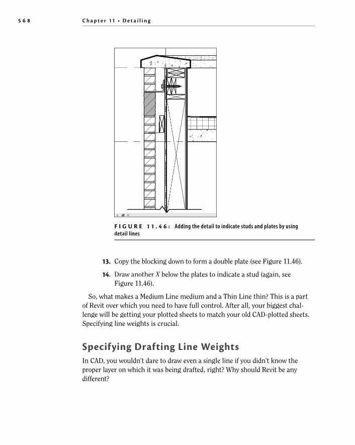
13. Copy the blocking down to form a double plate (see Figure 11.46 ).
14. Draw another X below the plates to indicate a stud (again, seeXFigure 11.46 ).
So, what makes a Medium Line medium and a Thin Line thin? This is a part of Revit over which you need to have full control. After all, your biggest chal-lenge will be getting your plotted sheets to match your old CAD-plotted sheets.Specifying line weights is crucial.
Specifying Drafting Line Weights In CAD, you wouldn’t dare to draw even a single line if you didn’t know the proper layer on which it was being drafted, right? Why should Revit be any different?
F I G U R E 1 1 . 4 6 : Adding the detail to indicate studs and plates by usingdetail lines

D r a f t i n g o n To p o f t h e D e t a i l 5 6 9
The objective of the next procedure is to investigate where the line weights arestored and how they relate to the lines you’re drawing.
1. On the Manage tab, choose Additional Settings ➢ Line Styles.
2. In the Line Styles dialog box, expand the Lines category by clickingthe plus sign next to Lines. Some of the line styles were generated inAutoCAD.
3. Click into the Wide Lines category, and change the value from 5 to 4 , as shown in Figure 11.47 .
F I G U R E 1 1 . 4 7 : Changing Wide Lines from 5 to 4
4. Click OK. Wide Lines in all project views will now show the new lineweight.
The next item to tackle is the fact that this detail looks naked without any textor dimensions added to it. Although you’ve applied both of these items in past chapters, you need to use them because they’re relevant to detailing.

5 7 0 C h a p t e r 11 • D e t a i l i n g
Do What D 5 and 4 Represent? In Revit, line weights are sorted from thinnest to heaviest. You can add additional line weights, but I recommend you stick to the 16 available. To see where these settings are stored, choose Additional Settings ➢ Line Weights. In the Line Weightsdialog box, the numbers 1 through 16 are listed. These numbers represent what you see in the Line Styles dialog box. Also notice that the thicker line weights degrade in thickness as the scale is reduced (shown here):
Adding Notes In Revit, adding notes to a section can take on a whole different meaning than in CAD.
Or, if you want, adding notes to a detail can be exactly as it was back in CAD. Sometimes, sticking to the tried-and-true method isn’t such a bad thing.
The goal of the next set of procedures is to add notes by simply leadering in some text.
Adding Textual Notations We’re duplicating efforts with text to drive home the fact that Revit lets you addtext regardless of the view and also regardless of the scale. Text in a plan is thesame as text in a detail, and you’ll prove it in the next procedure:
1. On the Annotate tab, click the Text button.

A d d i n g N o t e s 5 7 1
2. The next three steps use the Format panel of the Modify | Place Text tab (see Figure 11.48 ). Click the Align Right button.
F I G U R E 1 1 . 4 8 : Adding the leadered text
3. Again, on the Modify | Place Text tab, click the Two Segments leader(the uppercase A in the lower-left corner of the Format panel; seeFigure 11.48 ).
4. Also on the Format panel, click the Leader At Top Right button.
5. In the section, pick the fi rst point of the leader at the top of the bricktie detail (shown in Figure 11.48 ).
6. Pick the second point above and to the left of the fi rst point (shown inFigure 11.48 ).
7. Pick the third point for the second segment (as shown in Figure 11.48 ).
8. Type the note CORRUGATED BRICK TIE ON 2X6 BLOCKING .
9. Click off the text into another part of the model, and your text justi-fi es to the leader.

5 7 2 C h a p t e r 11 • D e t a i l i n g
10. Press Esc twice.
11. Select the text.
12. Pick the grip to the left, and drag the box to resemble Figure 11.49 . The text wraps.
F I G U R E 1 1 . 4 9 : Wrapping the text
13. Save the model.
These steps are the most common procedure for adding detail to a model. In other words, take what you can from the model, and then add linework and detail components to the view. However, eventually you’ll fi nd yourself in a situ-ation where you would rather draft your detail from scratch. You can do this as well, as you’ll see in the next section.
Creating Blank Drafting Views Over the years, Revit has been labeled as a “poor drafting application.” Thisis unfortunate because it can be a good drafting application when given the chance. The only challenge is to fi gure out where to start!

C r e a t i n g B l a n k D r a f t i n g V i e w s 5 7 3
The objective of the next procedure is to create a blank view and then simply learn how to draw lines.
1. On the View tab, click the Drafting View button, as shown in Figure 11.50 .
F I G U R E 1 1 . 5 0 : Click the Drafting View button on the View tab.
2. In the New Drafting View dialog box, name the new view TYPICAL WALL TERMINATION .
3. Change the scale to 3/4 = 1 –0 (1:20 for the metric users). (SeeFigure 11.51 .)
F I G U R E 1 1 . 5 1 : Changing the view name and scale
4. Click OK.
You’re now in a completely blank canvas. Anything you draw here is truly drafting, and it isn’t tied back to the model at all.
The objective of the next procedure is to start adding lines and more detailcomponents. The item you’ll draft is a detail showing a fl exible top track of ametal-stud partition.
1. On the Annotate tab, click the Detail Line button.
2. In the Properties dialog box, click Medium Lines.

5 7 4 C h a p t e r 11 • D e t a i l i n g
3. Draw a horizontal line about 4 –7 (1375 mm) long, as shown in Figure 11.52 .
F I G U R E 1 1 . 5 2 : Drawing a detail line approximately 4 –7 (1375 mm)
4. With the Detail Line command still running, change the Offset set-ting in the Options bar to 8 ( 200 mm).
5. Using the two endpoints of the fi rst line, draw another line below.
own There Get Do Remember, if your line is above the first line you drew, press the spacebar to flip the line down below the first, as shown here:
6. On the Draw panel, click the Pick Lines icon.
7. Again, on the Options bar, change Offset to 1 1/2 (38 mm).
8. Offset the bottom line down 1 1/2 (38 mm). Your detail should look like Figure 11.53 .
9. With the Detail Line command still running, click the Line button,and set the Offset value to 3 (75 mm).

C r e a t i n g B l a n k D r a f t i n g V i e w s 5 7 5
10. On the Options bar, make sure the Chain option is deselected.
11. For the fi rst point of the line, pick the midpoint of the bottom line, asshown in Figure 11.54 .
F I G U R E 1 1 . 5 3 : Using Pick Lines and adding an offset of 1 1/2 (38 mm)
F I G U R E 1 1 . 5 4 : By setting an offset of 3 (75 mm), you can draw two lines using a common centerline.
12. For the second point of the line, pick a point about 1 –9 (525 mm),straight down, as shown in Figure 11.54 . (This draws a line offset 3[75 mm] to the right from the center of the line above.)
13. To draw the other line, pick the same midpoint you picked to drawthe fi rst line.

5 7 6 C h a p t e r 11 • D e t a i l i n g
14. Move your cursor down the view, but this time tap the spacebar to fl ip the line to the other direction (see Figure 11.55 ).
F I G U R E 1 1 . 5 5 : The detail up to this point
15. Draw another line of the same length (again, see Figure 11.55 ).
16. Click Modify.
17. Compare your lines with the lines in Figure 11.55 .
18. Click the Trim/Extend To Corner button on the Modify tab, as shown in Figure 11.56 .
F I G U R E 1 1 . 5 6 : Trimming the corners

C r e a t i n g B l a n k D r a f t i n g V i e w s 5 7 7
19. Trim the edges of the top of the wall (see Figure 11.56 ).
The next step is to add the track to the bottom of the fl oor. You’ll do this bycreating three wide lines. The trick is to do a good amount of offsetting. If you want to explore and try the procedure on your own, look ahead to Figure 11.57and try to match it dimensionally. Remember, you’re using wide lines for thetrack.
F I G U R E 1 1 . 5 7 : Offsetting the heavy lines 3/8 (9 mm) to the right and the left
If you would rather have guidelines, follow these steps:
1. On the Annotate tab, click the Detail Line button.
2. In the Properties dialog box, click Wide Lines.
3. On the Draw panel, click the Pick Lines button.
4. On the Options bar, set Offset to 1/8 (3 mm).
5. Offset the bottom of the fl oor down 1/8 (3 mm). (It will look like the bottom line simply got thicker, but when you trim it up, it willlook right.)
6. With the Detail Line command still running, set Offset to 3/8( 9 mm).
7. Offset the left and the right lines, as shown in Figure 11.57 .
8. Offset the bottom of the “fl oor” down 3 (75 mm).
9. Extend the tops of the left and right thick vertical lines to the thickhorizontal line.
10. Trim the bottoms of the thick vertical lines to the 3 (75 mm) hori-zontal line, as shown in Figure 11.58 .

5 7 8 C h a p t e r 11 • D e t a i l i n g
11. Trim the top horizontal line to the new vertical lines.
12. Delete the 3 (75 mm) horizontal line. Your detail should now look like Figure 11.59 .
F I G U R E 1 1 . 5 8 : Offsetting the thick lines
F I G U R E 1 1 . 5 9 : The top track is now in place.
It’s time to add the gypsum to both sides of the wall. By using the same method as you did before, you’ll use thin lines to denote two layers of 5⁄8 (15 mm) gypsum on both sides of the stud. If you’re ready to complete this task onyour own, go ahead. (Remember, you’re adding two layers of 5⁄8 [15 mm] gyp-sum to both sides of the wall, and you’re using thin lines to denote this.)
If you would rather have some guidelines with which to practice, let’s step through the procedure:
1. On the Annotate tab, click the Detail Line button.
2. Select Thin Lines in the Properties dialog box.
3. On the Draw panel, click the Pick Lines icon, as shown inFigure 11.60 .

C r e a t i n g B l a n k D r a f t i n g V i e w s 5 7 9
4. Type 5/8 (15 mm) in the Offset fi eld.
5. Offset two lines in from the right and the left (see Figure 11.60 ).
Look at this: the steps are getting shorter. You used only the Detail Line com-mand but have successfully offset every line you needed without leaving thecommand that you were running at the time. Who says you can’t draft in Revit?
The next procedure involves adding a fi lled region to the “fl oor.” Although youdon’t want to be too specifi c about what you’re calling out, you still need somecontrasting hatch.
1. On the Annotate tab, click the Region ➢ Filled Region button.
F I G U R E 1 1 . 6 0 : Adding the lines for the gypsum

5 8 0 C h a p t e r 11 • D e t a i l i n g
2. In the Line Style panel, select <Invisible Lines>, as shown in Figure 11.61 . On the Options bar, pick Chain.
F I G U R E 1 1 . 6 1 : Draw the filled region with invisible lines.
F I G U R E 1 1 . 6 2 : The detail with the hatching included
Or, if you would like to venture out on your own, try to duplicate Figure 11.62 . You’ll need to add a fi lled region using diagonal lines. If you would rather followthe procedure, let’s get started.
C r e a t i n g B l a n k D r a f t i n g V i e w s 5 8 1
3. Draw a boundary (see Figure 11.61 ), and press Esc.
4. In the Properties dialog box, click the Edit Type button.
5. Click Duplicate.
6. Call the new region ROOF . FF
7. Change Fill Pattern to Diagonal Up-Small [Drafting].
N O T E Remember to change the Fill pattern by clicking the […] button after youclick in the Value cell. You can then browse to find the pattern that you’re looking for in the menu.
8. Click OK.
9. Click Finish Edit Mode on the Mode panel. Your pattern should looklike Figure 11.62 . (Remember, the loop must be completely closed,with no gaps or overlaps.)
This detail is looking good—so good that it would be nice to never have to draw it again. Let’s proceed with creating a special group that you can drag onto another view.
Creating a Detail Group Groups can be extremely advantageous to the drafting process. Although Imentioned earlier that details and drafting views aren’t linked to the model, youcan still provide some global control within the details themselves by creating a group. This will give you further control over every instance of this specifi cdetail in the entire model.
The objective of the following procedure is to create a new group and add it toanother view:
1. Select everything in the view by picking a window.
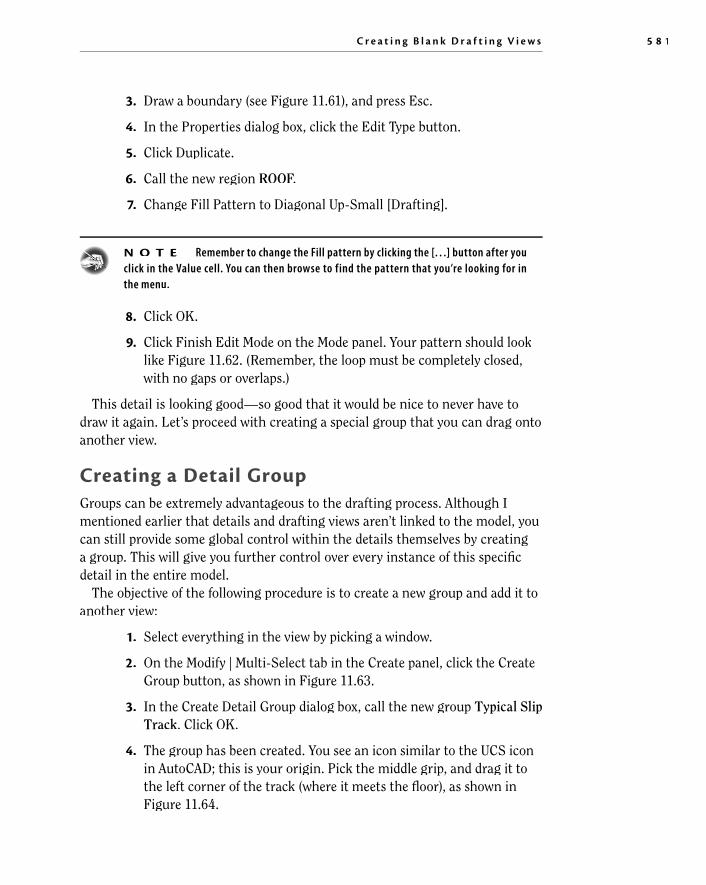
2. On the Modify | Multi-Select tab in the Create panel, click the Create Group button, as shown in Figure 11.63 .
3. In the Create Detail Group dialog box, call the new group Typical SlipTrack . Click OK.
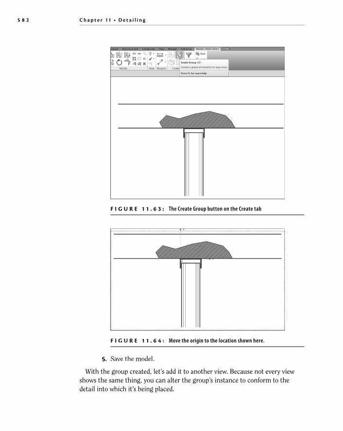
4. The group has been created. You see an icon similar to the UCS icon in AutoCAD; this is your origin. Pick the middle grip, and drag it tothe left corner of the track (where it meets the fl oor), as shown in Figure 11.64 .
5 8 2 C h a p t e r 11 • D e t a i l i n g
5. Save the model.
With the group created, let’s add it to another view. Because not every viewshows the same thing, you can alter the group’s instance to conform to the detail into which it’s being placed.
F I G U R E 1 1 . 6 3 : The Create Group button on the Create tab
F I G U R E 1 1 . 6 4 : Move the origin to the location shown here.
C r e a t i n g B l a n k D r a f t i n g V i e w s 5 8 3
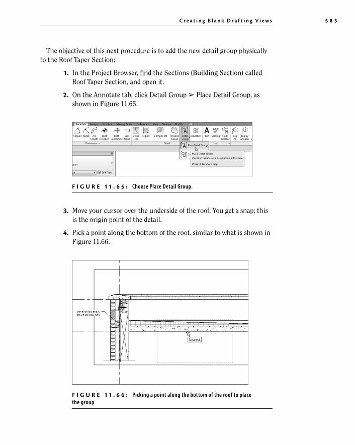
The objective of this next procedure is to add the new detail group physically to the Roof Taper Section:
1. In the Project Browser, fi nd the Sections (Building Section) called Roof Taper Section, and open it.
2. On the Annotate tab, click Detail Group ➢ Place Detail Group, as shown in Figure 11.65 .
F I G U R E 1 1 . 6 5 : Choose Place Detail Group.
3. Move your cursor over the underside of the roof. You get a snap; this is the origin point of the detail.
4. Pick a point along the bottom of the roof, similar to what is shown in Figure 11.66 .
F I G U R E 1 1 . 6 6 : Picking a point along the bottom of the roof to placethe group

5 8 4 C h a p t e r 11 • D e t a i l i n g
5. When the group is placed, press Esc.
The next step is to remove some of the extraneous hatch and lines. You can dothis within a group, but you must be careful not to edit the group in a way thataffects all other instances:
1. Hover your cursor over the bottom line of the fi lled region, as shownin Figure 11.67 .
F I G U R E 1 1 . 6 8 : The slip track without the filled region
F I G U R E 1 1 . 6 7 : Excluding an element from the group
2. Press the Tab key. This allows you to select the fi lled region.
3. Pick the region (see Figure 11.67 ).
4. A small, blue group icon appears. When you hover your cursor over it, it says that you can exclude this member from the group. This is what you want to do, so click the button.
5. Repeat the process for the top fl oor line.
6. Repeat the process for the hatch.
7. Save the model. Your detail should now look like Figure 11.68 .
C r e a t i n g B l a n k D r a f t i n g V i e w s 5 8 5
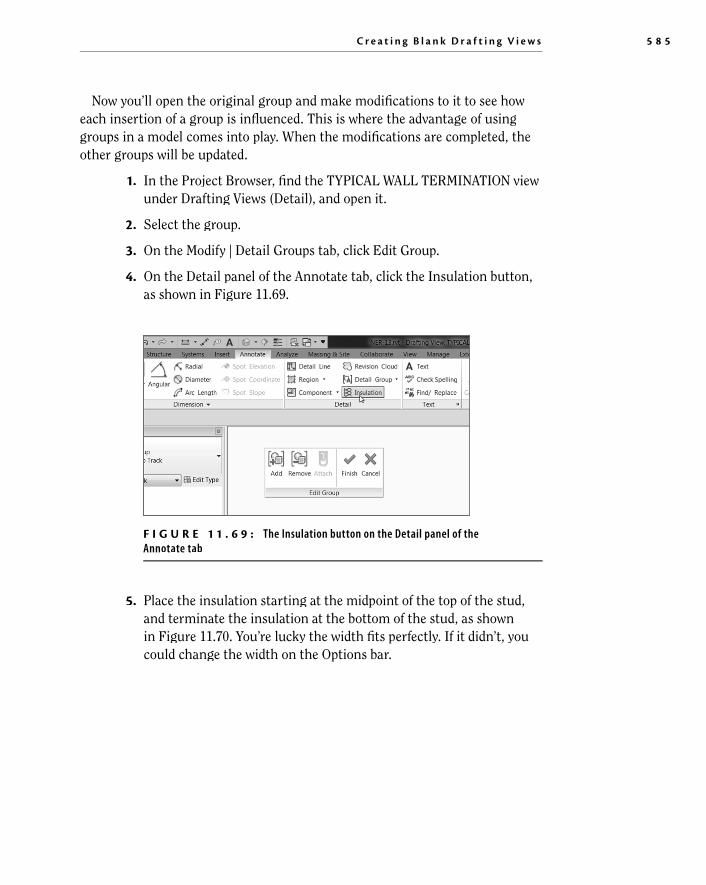
Now you’ll open the original group and make modifi cations to it to see howeach insertion of a group is infl uenced. This is where the advantage of usinggroups in a model comes into play. When the modifi cations are completed, the other groups will be updated.
1. In the Project Browser, fi nd the TYPICAL WALL TERMINATION viewunder Drafting Views (Detail), and open it.
2. Select the group.
3. On the Modify | Detail Groups tab, click Edit Group.
4. On the Detail panel of the Annotate tab, click the Insulation button,as shown in Figure 11.69 .
F I G U R E 1 1 . 6 9 : The Insulation button on the Detail panel of theAnnotate tab
5. Place the insulation starting at the midpoint of the top of the stud, and terminate the insulation at the bottom of the stud, as shownin Figure 11.70 . You’re lucky the width fi ts perfectly. If it didn’t, you could change the width on the Options bar.

5 8 6 C h a p t e r 11 • D e t a i l i n g
6. Click the Finish button on the Edit Group toolbar, as shown inFigure 11.71 .
F I G U R E 1 1 . 7 0 : Drawing the insulation
F I G U R E 1 1 . 7 1 : The Finish button on the Edit Group toolbar
7. Open the Roof Taper Section, and observe that the insulation has been added.
You’re starting to understand detailing pretty well. There are two issues left to discuss. First, it would be nice to reference these details from the plan, evenknowing that they aren’t physically tied into the model. Second, you need toknow how to import CAD into a detail.

C r e a t i n g B l a n k D r a f t i n g V i e w s 5 8 7
s Be Aware of the Project Browser Always You can add a group from the Project Browser as well. If you scroll down in the Project Browser, you’ll see a category called Groups. Expand the Groups category, and locate the Detail category. Expand this, and find the Typical Slip Track group, as shown here. All you need to do is click this group and drag it into the model.
Adding a Section to Another View You already know how to add a section marker in plan. What you may not know is how to tell Revit that you would rather specify the reference.
In this procedure, you’ll go to the Level 1 ceiling plan and add a section point-ing to your drafting view:
1. In the Project Browser, open the Level 1 fl oor plan.
2. Zoom in on the area of the east wing shown in Figure 11.72 .
3. On the View tab, click the Section button. Pick Detail in the TypeSelector.
4. Before you place the section, click the Reference Other View buttonon the Options bar.

5 8 8 C h a p t e r 11 • D e t a i l i n g
5. In the menu to the right of the Reference Other View label,expand the drop-down and select Drafting View: TYPICAL WALLTERMINATION.
6. Place the section into the model (see Figure 11.72 ).
7. Press Esc.
8. Double-click the section marker that you placed in the model. Doingso opens your drafting view.
9. Save the model.
W A R N I N G Be careful! In AutoCAD and MicroStation, you got used to doing this type of referencing daily. In Revit, your co-workers may not be accustomed to this inaccurate style. Be deliberate when you add sections referring to other views, and try not to do it too often.
Creating a drafting view is behind you. Now it’s time to look at our old friendCAD. (Some may say that the new meaning of the acronym is Ctrl+Alt+Delete.)Regardless of the existing sentiment toward CAD, it did get us this far. And we still need it—more so in the drafting capacity. Yes, you can import CAD fi lesinto a detail.
F I G U R E 1 1 . 7 2 : Choosing the correct options while placing the section
C r e a t i n g B l a n k D r a f t i n g V i e w s 5 8 9
Importing AutoCAD Files into a Drafting View I’ll go out on a limb and venture to guess that you have a handful of CAD detailsthat you use on a daily basis. The question always is, “What do I do with this pile of details I spent years and thousands of dollars to create?” Well, you can stilluse them.
The objective of the next procedure is to create a new drafting view andimport an AutoCAD detail. If you would like, you can attempt to import yourown detail, or you can use the fi le provided. Just go to the book’s web page at www.sybex.com/go/revit2017ner . Browse to the Chapter 11 folder, and fi ndthe base cabinet.dwg fi le. You can then place it on your system for laterretrieval.
Follow these steps:
1. In the View tab, click the Drafting View button.
2. In the next dialog box, name the new view TYPICAL BASECABINET . T
3. Set Scale to 1 1/2 = 1 –0 , and then click OK.
4. On the Insert tab, click the Import CAD button.
5. Browse to the location where you placed your CAD fi le.
6. Select the fi le, but don’t click Open yet.
7. At the bottom of the Import dialog box, set Colors to Black And White.
8. Set Layers to All.
9. Set Import Units to Auto-Detect.
10. Set Positioning to Auto – Center To Center.
11. Click Open.
12. Type ZA. The detail should now be in full view.
13. Select the detail.
14. On the Modify | Base cabinet.dwg tab, click Explode ➢ Full Explode.
15. Select one of the fi lled regions.
16. In the Properties dialog box, click Edit Type.
17. Change Fill Pattern to Sand – Dense, and select the Drafting radio button.

5 9 0 C h a p t e r 11 • D e t a i l i n g
18. Click OK.
19. Click OK one more time to get back to the model.
20. Make sure your cabinet is hatched properly.
21. Save the model.
e Builder Button! Use th To change the pattern to Sand, make sure you click the […] button next to the area that says Fill Pattern, as shown here. From there, you can choose the hatch pattern.
Up to this point, you’ve been using detail lines for your drafting. The one issue is that detail lines are visible only in the specifi c view in which you’re working. Suppose you wanted linework to show up both in plan/elevation and in a 3Dview. In this situation, you should use the Model Lines tool.
Adding 2D and 3D Lines to the Model Just because you’re drafting, that doesn’t mean you can’t create lines in all views, such as in a 3D view in a 3D function. Revit has a tool that is simply calledModel Lines , and you use it to project lines into multiple views. You apply the Lines tool just like a detail line—only it behaves the same as a Revit 3D family in that you can see it in every view (unless you turn it off).

C r e a t i n g B l a n k D r a f t i n g V i e w s 5 9 1
In this procedure, you’ll add detail lines to the west sloping roof. They’re nothing fancy, but you’ll quickly get the idea of how to use this feature.
1. In the Project Browser, fi nd the West Roof fl oor plan, and open it.
2. On the Architecture tab, click the Set button in the Work Plane panel,as shown in Figure 11.73 .
F I G U R E 1 1 . 7 3 : The Set button on the Work Plane panel of the Architecture tab
3. In the Work Plane dialog box, select the Pick A Plane radio button.
4. Click OK.
5. Pick the roof, as shown in Figure 11.74 .
F I G U R E 1 1 . 7 4 : Picking the roof. Your work plane is now set to slope with theroof. Anything you draw will be on this sloping plane.

5 9 2 C h a p t e r 11 • D e t a i l i n g
6. On the Model panel of the Architecture tab, click the Model Linebutton.
7. In the Line Style menu, select Medium Lines, as shown in Figure 11.75 .
F I G U R E 1 1 . 7 5 : Select Medium Lines under Line Style.
8. On the Draw panel, click the Start-End-Radius Arc button, as shownin Figure 11.76 .
F I G U R E 1 1 . 7 6 : Drawing an 80 –0 (24 m) radius arc

A r e Yo u E x p e r i e n c e d ? 5 9 3
9. Draw an arc from the two endpoints shown in Figure 11.76 . Makethe radius 80 –0 ( 24000 mm). Simply enter the numbers on thekeyboard and press Enter, and they will fi ll in the radius fi eld. Click Modify.
10. Go to an exterior 3D view. You can still see the arc.
11. Save the model.
It’s a good idea to keep this feature in mind. This drafting tool will becomeuseful when it comes to sketching in 3D. There will be many situations in whichyou’ll use this little nugget.
Are You Experienced? Now you can…
✔ modify and add line weights to be used in both the 3D and 2Denvironments
✔ add linework in a drafting view as well as a 2D and 3D view
✔ create both masking regions and fi lled regions to provide hatching to a model
✔ mask an area so that you can draft over it
✔ add detail components to the model and create repeating details
✔ modify detail families to suit your needs
✔ create a group to be used in multiple drafting views, change thegroup, and update each copy in each view
✔ create a new drafting view to draft from scratch and import a CAD fi le into a drafting view