Designing for Ultra-Low-Power with MSP430 · Designing for Ultra-Low Power with MSP430 ......
37
© 2006 Texas Instruments Inc, Slide 1 Designing for Ultra-Low Power with MSP430 Christian Hernitscheck MSP430 FAE Europe Texas Instruments
Transcript of Designing for Ultra-Low-Power with MSP430 · Designing for Ultra-Low Power with MSP430 ......

© 2006 Texas Instruments Inc, Slide 1
Designing for Ultra-Low Powerwith MSP430
Christian HernitscheckMSP430 FAE Europe
Texas Instruments

© 2006 Texas Instruments Inc, Slide 2
• Introduction to Ultra-Low Power• Looking for Ultra-Low Power Parts• MSP430 – The Ultra-Low Power MCU• Low-Power Efficient Coding Techniques• Summary
Agenda

© 2006 Texas Instruments Inc, Slide 3
Achieving Ultra-low Power
Always-on
On demand
• Extended Ultra-low Power standby mode• Minimum active duty cycle• Performance on-demand

© 2006 Texas Instruments Inc, Slide 4
OffAll
Clocks Off0.1uA
OffAll
Clocks Off0.1uA
Stand-byDCO offACLK on0.8uA
Stand-byDCO offACLK on0.8uA
LPM3RTC functionLCD driverRAM/SFR retained
CPU OffDCO on
ACLK on35uA
CPU OffDCO on
ACLK on35uA
<6us
<6us
Ultra-low Power Clock Control
LPM0 LPM4RAM/SFR retained
ActiveDCO on
ACLK on250uA
ActiveDCO on
ACLK on250uA

© 2006 Texas Instruments Inc, Slide 5
• Introduction to Ultra-Low Power• Looking for Ultra-Low Power Parts• MSP430 – The Ultra-Low Power MCU• Low-Power Efficient Coding Techniques• Summary
Agenda
© 2006 Texas Instruments Inc, Slide 6
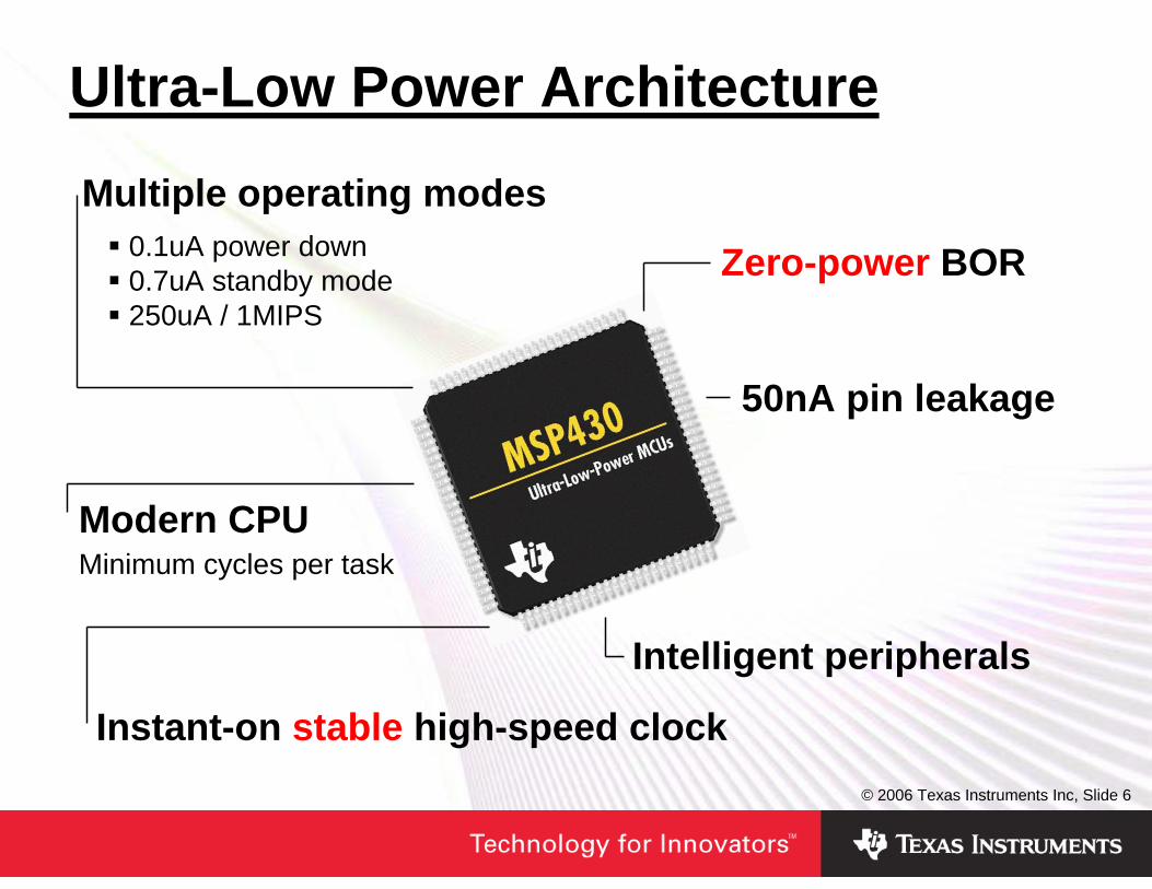
Modern CPUMinimum cycles per task
Multiple operating modes
Instant-on stable high-speed clock
Zero-power BOR
Intelligent peripherals
50nA pin leakage
0.1uA power down0.7uA standby mode250uA / 1MIPS
Ultra-Low Power Architecture

© 2006 Texas Instruments Inc, Slide 7
• CMOS Inverter:
• Power Consumption of a CMOS Inverter:
Power Consumption in CMOS Designs
P = Pstat + PQ + Pdyn Pstat = Vcc * ILL
PQ = β / 12 * (Vcc – 2*UTn)3 * τ / TPdyn = CL* f * Vcc2
Vin
I
Vcc
t
t

© 2006 Texas Instruments Inc, Slide 8
MCU‘s Digital Supply Current
MSP430
AVccAVssDVccDVss
Reset
CPU Clock
Vcc+
-
CH2
CH1
© 2006 Texas Instruments Inc, Slide 9
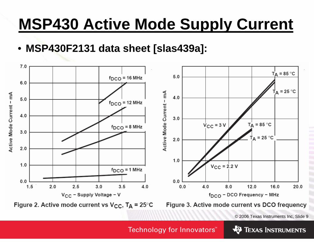
• MSP430F2131 data sheet [slas439a]:
MSP430 Active Mode Supply Current

© 2006 Texas Instruments Inc, Slide 10
Device, Voltage, Temperature & Clock
• Die size and # pins • Family architectures and clock system
MSP430F16x LPM3
MSP430F20xx LPM3
LFXT1
VLO

© 2006 Texas Instruments Inc, Slide 11
Power Manage Internal Peripherals
Comparator_A
P1OUT |= 0x02; // Power dividerCACTL1 = CARSEL + CAREF_2 + CAON; // Comp_A onif (CAOUT & CACTL2)P1OUT |= 0x01; // FaultelseP1OUT &= ~0x01;
P1OUT &= ~0x02; // de-power divider CACTL1 = 0; // Disable Comp_A
P1OUT |= 0x02; // Power dividerCACTL1 = CARSEL + CAREF_2 + CAON; // Comp_A onif (CAOUT & CACTL2)P1OUT |= 0x01; // FaultelseP1OUT &= ~0x01;
P1OUT &= ~0x02; // de-power divider CACTL1 = 0; // Disable Comp_A

© 2006 Texas Instruments Inc, Slide 12
Integrated Analog Power ManagingADC10
DAC12
OA

© 2006 Texas Instruments Inc, Slide 13
• Introduction to Ultra-Low Power• Looking for Ultra-Low Power Parts• MSP430 – The Ultra-Low Power MCU• Low-Power Efficient Coding Techniques• Summary
Agenda
© 2006 Texas Instruments Inc, Slide 14
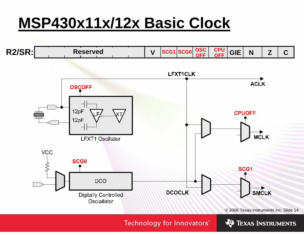
MSP430x11x/12x Basic Clock
R2/SR: CSCG1 SCG0 ZNGIECPUOFF
OSCOFFVReserved

© 2006 Texas Instruments Inc, Slide 15
Performance on Demand
• Immediate-stable clock start for reaction to events
Interrupt
DCO

© 2006 Texas Instruments Inc, Slide 16
• Assembler Code Example:
• C Code Example:
Low Power Mode Configuration
Active Mode 0 0 0 0 ~ 250uA
bis.w #CPUOFF,SR ; LPM0bis.w #CPUOFF,SR ; LPM0
_BIS_SR (CPUOFF); // LPM0_BIS_SR (CPUOFF); // LPM0
LPM0 0 0 0 1 ~ 35uA
LPM3 1 1 0 1 ~ 0.8uA
LPM4 1 1 1 1 ~ 0.1uA
R2/SR: CSCG1 SCG0 ZNGIECPUOFF
OSCOFFVReserved

© 2006 Texas Instruments Inc, Slide 17
ISR hardware - automaticallyPC pushed SR pushedInterrupt vector moved to PCSR is clearedIFG flag cleared on single source flags
reti - automaticallySR popped - originalPC popped
Prior to ISRSP
Item1Item2
PCSR
SP
SP
Item1Item2
Item1Item2
PCSR
Interrupt Processing

© 2006 Texas Instruments Inc, Slide 18
ORG 0F000h RESET mov.w #300h,SP
mov.w#WDT_MDLY_32,&WDTCTL
bis.b #WDTIE,&IE1 bis.b #01h,&P1DIR
Mainloop bis.w #CPUOFF+GIE,SR xor.b #01h,&P1OUT jmp Mainloop
WDT_ISR bic.w #CPUOFF,0(SP)reti
ORG 0FFFEh DW RESET ORG 0FFF4h DW WDT_ISR
ORG 0F000h RESET mov.w #300h,SP
mov.w#WDT_MDLY_32,&WDTCTL
bis.b #WDTIE,&IE1 bis.b #01h,&P1DIR
Mainloop bis.w #CPUOFF+GIE,SR xor.b #01h,&P1OUT jmp Mainloop
WDT_ISR bic.w #CPUOFF,0(SP)reti
ORG 0FFFEh DW RESET ORG 0FFF4h DW WDT_ISR
Item1Item2
PCSR=0018
SP
SP
Item1Item2
PCSR
Item1Item2
PCSR=0008
SPItem1Item2
Low Power Modes In Assembler

© 2006 Texas Instruments Inc, Slide 19
void main(void){ WDTCTL = WDT_MDLY_32; IE1 |= WDTIE; P1DIR |= 0x01;
for (;;){_BIS_SR(CPUOFF + GIE);P1OUT ^= 0x01;
}}#pragma vector=WDT_VECTOR__interrupt void watchdog_timer(void){
_BIC_SR_IRQ(CPUOFF); }
void main(void){ WDTCTL = WDT_MDLY_32; IE1 |= WDTIE; P1DIR |= 0x01;
for (;;){_BIS_SR(CPUOFF + GIE);P1OUT ^= 0x01;
}}#pragma vector=WDT_VECTOR__interrupt void watchdog_timer(void){
_BIC_SR_IRQ(CPUOFF); }
Low Power Modes In C
Item1Item2
PCSR=0018
Item1Item2
Item1Item2
PCSR
Item1Item2
PCSR=0008
SP
SP
SP

© 2006 Texas Instruments Inc, Slide 20
2xx Basic Clock Module+ with VLO Clock
• VLO provides crystal alternative
• Lower power• < 500 nano-amp
© 2006 Texas Instruments Inc, Slide 21
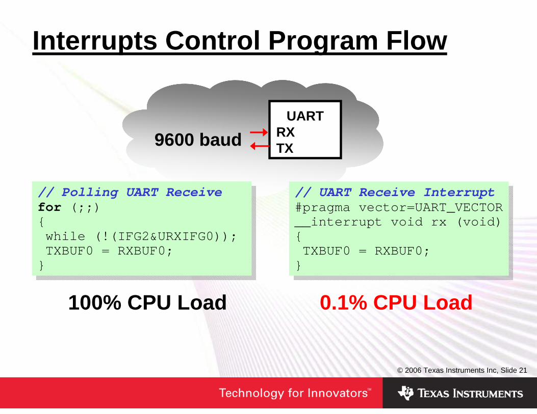
100% CPU Load
Interrupts Control Program Flow
UARTRXTX
0.1% CPU Load
9600 baud
// Polling UART Receivefor (;;){while (!(IFG2&URXIFG0));TXBUF0 = RXBUF0;}
// Polling UART Receivefor (;;){while (!(IFG2&URXIFG0));TXBUF0 = RXBUF0;}
// UART Receive Interrupt#pragma vector=UART_VECTOR__interrupt void rx (void){TXBUF0 = RXBUF0;}
// UART Receive Interrupt#pragma vector=UART_VECTOR__interrupt void rx (void){TXBUF0 = RXBUF0;}

© 2006 Texas Instruments Inc, Slide 22
100% CPU Load
Software Functions >> Peripherals
MCUP1.2
Zero CPU Load
// Setup output unitCCTL1 = OUTMOD0_1; _BIS_SR(CPUOFF);
// Setup output unitCCTL1 = OUTMOD0_1; _BIS_SR(CPUOFF);
// Endless Loop for (;;) {P1OUT |= 0x04; // Set delay1();P1OUT &= ~0x04; // Resetdelay2();}
// Endless Loop for (;;) {P1OUT |= 0x04; // Set delay1();P1OUT &= ~0x04; // Resetdelay2();}

© 2006 Texas Instruments Inc, Slide 23
MSP430 ADC10• 10-bit ADC• 200ksps+• Autoscan• Single
Sequence Repeat-single Repeat-sequence
• Internal/external reference
• TA SOC triggers • Direct transfer
controller (DTC)
© 2006 Texas Instruments Inc, Slide 24
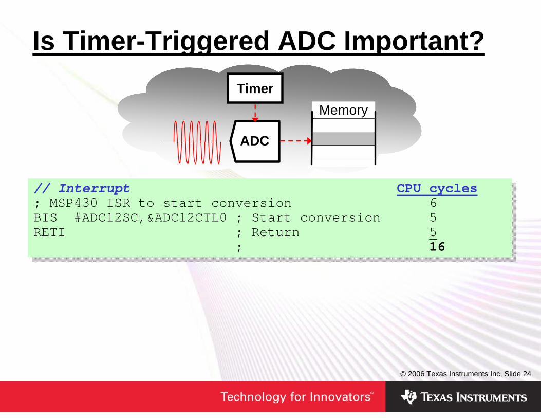
Is Timer-Triggered ADC Important?
Memory
ADC
Timer
// Interrupt CPU cycles; MSP430 ISR to start conversion 6 BIS #ADC12SC,&ADC12CTL0 ; Start conversion 5 RETI ; Return 5
; 16
// Interrupt CPU cycles; MSP430 ISR to start conversion 6 BIS #ADC12SC,&ADC12CTL0 ; Start conversion 5 RETI ; Return 5
; 16

© 2006 Texas Instruments Inc, Slide 2570 cycles/Sample Fully Automatic
Why Is Autoscan + DTC Important?Data2Data1Data0Data2
ADCDTCA
UTO
// Autoscan + DTC_BIS_SR(CPUOFF);
// Autoscan + DTC_BIS_SR(CPUOFF);
// SoftwareRes[pRes++] = ADC10MEM;ADC10CTL0 &= ~ENC; if (pRes < NR_CONV) {CurrINCH++;if (CurrINCH == 3) CurrINCH = 0;
ADC10CTL1 &= ~INCH_3; ADC10CTL1 |= CurrINCH; ADC10CTL0 |= ENC+ADC10SC;}
// SoftwareRes[pRes++] = ADC10MEM;ADC10CTL0 &= ~ENC; if (pRes < NR_CONV) {CurrINCH++;if (CurrINCH == 3) CurrINCH = 0;
ADC10CTL1 &= ~INCH_3; ADC10CTL1 |= CurrINCH; ADC10CTL0 |= ENC+ADC10SC;}

© 2006 Texas Instruments Inc, Slide 26
Why Is DMA Important?
>>
Memory
Data DACDAC
// Interrupt CPU cycles DMA clocks; MSP430 ISR for one output waveform 6 0MOV @R5+,&DAC12_0DAT ; Update DAC0 5 2AND #1F,R5 ; Modulo pointer 2 0RETI ; Return 5 0
; 18 2
; MSP430 ISR for two output waveforms 6 0MOV @R5+,&DAC12_0DAT ; Update DAC0 5 2MOV @R5+,&DAC12_1DAT ; Update DAC1 5 2AND #3F,R5 ; Modulo pointer 2 0RETI ; Return 5 0
; 23 4

© 2006 Texas Instruments Inc, Slide 27
Low-Power Peripheral Features• ADC10 reference buffer automatically controlled• ADC10, ADC12, SD16 cores automatically controlled• Auto-scan ADC modes• Timer-triggered data conversion• I2C and USCI modules automatically enable clock• DAC and OA have speed vs. power settings
• What can I do without the CPU?

© 2006 Texas Instruments Inc, Slide 28
Power Manage External Devices
• OPA with shutdown can be 20x lower total power
0.01uA = Shutdown 20uA = Active---------------------------0.06uA = Average
1uA = Quiescent1uA = Active -----------------------1uA = Average

© 2006 Texas Instruments Inc, Slide 29
How To Terminate Unused Pins?
• Please see last page of chapter 2 in User’s Guide
0
10
20
30
40
0.0 V 0.5 V 1.0 V 1.5 V 2.0 V 2.5 V 3.0 V
Vin at P1.0 [V]
Icc
[uA
]
MSP430VccVss
P1.0
3.0V I
• Floating inputs cause additional current consumption!

© 2006 Texas Instruments Inc, Slide 30
• Introduction to Ultra-Low Power• Looking for Ultra-Low Power Parts• MSP430 – The Ultra-Low Power MCU• Low-Power Efficient Coding Techniques• Summary
Agenda

© 2006 Texas Instruments Inc, Slide 31
• Use CPU registers for calculations and dedicated variables
• Same code size for word or byte• Use word operations when possible
Bytes, Words & CPU Registers
; 16-bit addition Code/Cycles5405 add.w R4,R5 ; 1/1529202000202 add.w &0200,&0202 ; 3/6
; 8-bit addition5445 add.b R4,R5 ; 1/152D202000202 add.b &0200,&0202 ; 3/6
; 16-bit addition Code/Cycles5405 add.w R4,R5 ; 1/1529202000202 add.w &0200,&0202 ; 3/6
; 8-bit addition5445 add.b R4,R5 ; 1/152D202000202 add.b &0200,&0202 ; 3/6

© 2006 Texas Instruments Inc, Slide 32
Effect Of The Constant Generator
• Immediate values 0xFFFF, 0, 1, 2, 4, 8 generated in hardware
• Reduces code size and cycles
• Completely Automatic!
D3E20021 bis.b #002h,&P1OUT ; With CG
D0F200100021 bis.b #010h,&P1OUT ; Without CG
D3E20021 bis.b #002h,&P1OUT ; With CG
D0F200100021 bis.b #010h,&P1OUT ; Without CG
© 2006 Texas Instruments Inc, Slide 33
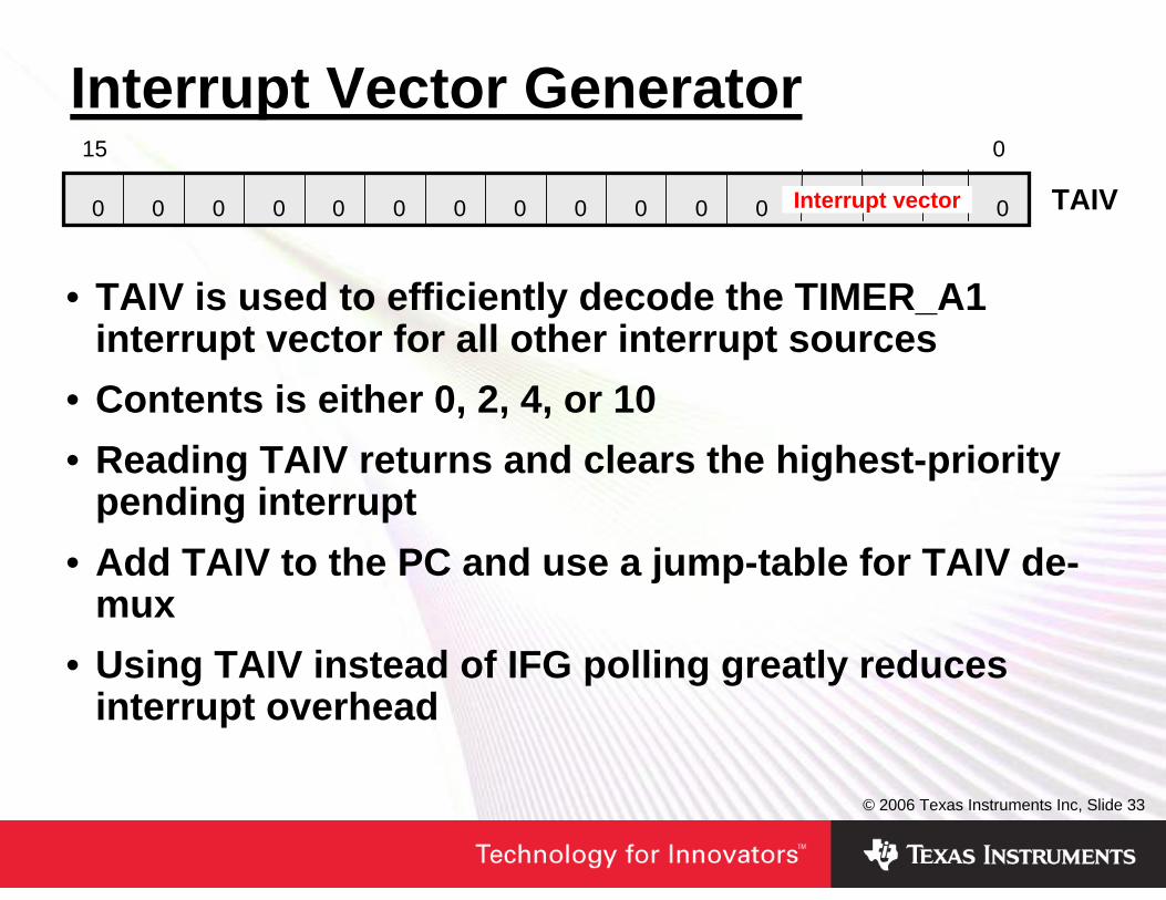
Interrupt Vector Generator
• TAIV is used to efficiently decode the TIMER_A1 interrupt vector for all other interrupt sources
• Contents is either 0, 2, 4, or 10• Reading TAIV returns and clears the highest-priority
pending interrupt• Add TAIV to the PC and use a jump-table for TAIV de-
mux• Using TAIV instead of IFG polling greatly reduces
interrupt overhead
TAIV0
015
Interrupt vector00000000000 0

© 2006 Texas Instruments Inc, Slide 34
C Coding Tips• Use local variable as much as possible. Local
variables use CPU registers whereas global variables use RAM.
• Use bit mask instead of bitfields for unsigned int and unsigned char.
• Use unsigned data types where possible• Use pointers to access structures and unions• Use “static const” class to avoid run-time copying
of structures, unions, and arrays.• Avoid modulo• Count down “for” loops• Get to know your C code and its disassembly!

© 2006 Texas Instruments Inc, Slide 35
• Introduction to Ultra-Low Power• Looking for Ultra-Low Power Parts• MSP430 – The Ultra-Low Power MCU• Low-Power Efficient Coding Techniques• Summary
Agenda

© 2006 Texas Instruments Inc, Slide 36
Principles For ULP Applications• Maximize the time in standby (LPM3)• Use interrupts to control program flow• Replace software functions with peripheral hardware• Power manage internal peripherals• Power manage external devices• Device choice can make a difference• Effective code is a must. Every unnecessary
instruction executed is a portion of the battery wasted that will never return.
x00geoff
Text Box
SLAP124

IMPORTANT NOTICE
Texas Instruments Incorporated and its subsidiaries (TI) reserve the right to make corrections, modifications, enhancements,improvements, and other changes to its products and services at any time and to discontinue any product or service without notice.Customers should obtain the latest relevant information before placing orders and should verify that such information is current andcomplete. All products are sold subject to TI’s terms and conditions of sale supplied at the time of order acknowledgment.
TI warrants performance of its hardware products to the specifications applicable at the time of sale in accordance with TI’sstandard warranty. Testing and other quality control techniques are used to the extent TI deems necessary to support thiswarranty. Except where mandated by government requirements, testing of all parameters of each product is not necessarilyperformed.
TI assumes no liability for applications assistance or customer product design. Customers are responsible for their products andapplications using TI components. To minimize the risks associated with customer products and applications, customers shouldprovide adequate design and operating safeguards.
TI does not warrant or represent that any license, either express or implied, is granted under any TI patent right, copyright, maskwork right, or other TI intellectual property right relating to any combination, machine, or process in which TI products or servicesare used. Information published by TI regarding third-party products or services does not constitute a license from TI to use suchproducts or services or a warranty or endorsement thereof. Use of such information may require a license from a third party underthe patents or other intellectual property of the third party, or a license from TI under the patents or other intellectual property of TI.
Reproduction of information in TI data books or data sheets is permissible only if reproduction is without alteration and isaccompanied by all associated warranties, conditions, limitations, and notices. Reproduction of this information with alteration is anunfair and deceptive business practice. TI is not responsible or liable for such altered documentation.
Resale of TI products or services with statements different from or beyond the parameters stated by TI for that product or servicevoids all express and any implied warranties for the associated TI product or service and is an unfair and deceptive businesspractice. TI is not responsible or liable for any such statements.
TI products are not authorized for use in safety-critical applications (such as life support) where a failure of the TI product wouldreasonably be expected to cause severe personal injury or death, unless officers of the parties have executed an agreementspecifically governing such use. Buyers represent that they have all necessary expertise in the safety and regulatory ramificationsof their applications, and acknowledge and agree that they are solely responsible for all legal, regulatory and safety-relatedrequirements concerning their products and any use of TI products in such safety-critical applications, notwithstanding anyapplications-related information or support that may be provided by TI. Further, Buyers must fully indemnify TI and itsrepresentatives against any damages arising out of the use of TI products in such safety-critical applications.
TI products are neither designed nor intended for use in military/aerospace applications or environments unless the TI products arespecifically designated by TI as military-grade or "enhanced plastic." Only products designated by TI as military-grade meet militaryspecifications. Buyers acknowledge and agree that any such use of TI products which TI has not designated as military-grade issolely at the Buyer's risk, and that they are solely responsible for compliance with all legal and regulatory requirements inconnection with such use.
TI products are neither designed nor intended for use in automotive applications or environments unless the specific TI productsare designated by TI as compliant with ISO/TS 16949 requirements. Buyers acknowledge and agree that, if they use anynon-designated products in automotive applications, TI will not be responsible for any failure to meet such requirements.
Following are URLs where you can obtain information on other Texas Instruments products and application solutions:
Products Applications
Amplifiers amplifier.ti.com Audio www.ti.com/audio
Data Converters dataconverter.ti.com Automotive www.ti.com/automotive
DSP dsp.ti.com Broadband www.ti.com/broadband
Interface interface.ti.com Digital Control www.ti.com/digitalcontrol
Logic logic.ti.com Military www.ti.com/military
Power Mgmt power.ti.com Optical Networking www.ti.com/opticalnetwork
Microcontrollers microcontroller.ti.com Security www.ti.com/security
RFID www.ti-rfid.com Telephony www.ti.com/telephony
Low Power www.ti.com/lpw Video & Imaging www.ti.com/videoWireless
Wireless www.ti.com/wireless
Mailing Address: Texas Instruments, Post Office Box 655303, Dallas, Texas 75265Copyright © 2007, Texas Instruments Incorporated