Designed, Manufactured and Supported in the USA … · 1 PRODUCT MANUAL Designed, Manufactured and...
29
1 PRODUCT MANUAL Designed, Manufactured and Supported in the USA SECURITY & COMMUNICATION SOLUTIONS 1600-IP Series ADA Compliant VoIP Emergency Phones January 12, 2018 VIKING Features Applications Specifications www.VikingElectronics.com ADA & CE Compliant VoIP Emergency Phones with Built-In Dialer and Digital Voice Announcer • Automatic polling and programming software included • 2 Amp relay contacts for door/gate or SL-2 strobe light control • SIP compliant (see pg 2 for list of compatible IP-PBX phone systems) • PoE powered (class 1, <4 watts) • Automatic Noise Canceling (ANC) feature for proper operation in noisy environments • VoIP eliminates the need for “Push to Talk” mode • Network downloadable firmware • Meets ADA requirements for Emergency Phones: - Automatically lights the Red “Call Connected” LED - Transmits a unique location I.D. code or voice announcement - Grade 2 Braille label for the visually impaired • Non-volatile digital voice announcer with 28 seconds of voice memory • T-10 Torx Security Screws for added security • Handsfree operation • Marine grade 316 stainless steel prevents corrosion on the stainless steel models • Laser etched graphics on stainless steel models • Dials up to 5 emergency numbers • E-1600-20-IP, E-1600-22-IP, E-1600-52-IP, and E-1600-TP2IPEWP dial up to 5 non- emergency “INFO” numbers • Cycles through backup phone numbers on busy or no-answer • Optional Enhanced Weather Protection (EWP), EWP products are designed to meet IP66 Ingress Protection Rating, see DOD 859 • Hangs up on busy signal, time-out or touch tone command • Extended temperature range (-40°F to 140°F) • 11 different chassis or board only available • Available in 42” tower phone model E-1600-BLTIPEWP (DOD 249) • Optional LV-1K Line verification Panel (DOD 246 ) • Optional PB-100 Polling System available (DOD 232) • Optional SL-2 or BLK-4-EWP strobe light kit available (DOD 242/654) • Optional E-1600A-MK-GNP Pedestal Mounting Kit (DOD 227) • Optional PB-1 Panic Button Kit (DOD 233) • Diagnostics (for testing mic, speaker & relay) Power: PoE class 1 (<4 watts) Maximum Sound Pressure: 95 dB SPL @ 1m. Dimensions: See Installation and Specifications Operating Temperature: -40°F to 140°F (-40° C to 60° C) Humidity - Standard Products: 5% to 95% non-condensing Humidity - EWP Products: Up to 100% Audio Codecs: G711u, G711a, G722 Network Compliance: IEEE 802.3 af PoE, SIP 2.0 RFC3261, 100BASE-TX with auto cross over Regulatory Compliance: CE, FCC Part 15 and Canada ICES-003 Class A Connections: (1) RJ45 10/100 Base-T, (3) gel-filled butt connectors * Americans with Disabilities Act of 1992 contains federal regu- lations regarding elevator telephones (Public Law 101-336). • Elevators • Parking ramps/lots • Emergency pool phones • ATM machines • Medical centers • Silent hold-up alarm dialer with an optional PB-1 Panic Button Kit (DOD 233) The 1600-IP Series ADA Compliant VoIP Emergency Phones are designed to provide quick and reliable handsfree communication for SIP VoIP phone systems with PoE. All 1600-IP Series phones meet ADA requirements for el- evator/ emergency telephones, and can be programmed from any Touch Tone phone or PC on the same LAN or remotely using a static IP address. The phones can dial up to 5 programmable emergency numbers. In addition, the E-1600-20-IP, E-1600-22-IP, E-1600-52-IP and E-1600-TP2IPEWP feature a second "INFO" button that will dial up to 5 non-emergency numbers. Two amp relay contacts are provided for strobe light, camera, door/gate control, etc. The 1600-IP Series phones can be programmed to automatically deliver a digital announcement to identify the location of the emergency call. Alternatively, a DTMF Touch Tone code may also be delivered. A “Call Connected” LED can be initiated manually or automatically. All programming parameters, including phone numbers and location numbers, are stored in non-volatile memory, requiring no batteries. All units are PoE powered. For outdoor installations where the unit is exposed to precipitation or condensation, select 1600-IP Series phones are available with Enhanced Weather Protection (EWP). EWP products feature foam rubber gaskets, sealed connections, gel-filled butt connectors, as well as urethane or thermal plastic potted circuit boards. For more information, see DOD 859. Installation requires the assistance of a Network Administrator / IT Technician. • Area of refuge locations • Lobbies • Entryways • Campus emergency stations • Stadiums • Convention centers • Public access areas E-1600-IP E-1600-45-IP E-1600-60-IP E-1600-65-IP E-1600-20-IP E-1600-22-IP E-1600-30-IP E-1600-32-IP E-1600-50/52-IP E-1600-53-IP ! E-1600-55-IP E-1600-03-IP E-1600-02-IP/E-1600-TP-IPEWP E-1600-TP2IPEWP/E-1600-GT-IPEWP
Transcript of Designed, Manufactured and Supported in the USA … · 1 PRODUCT MANUAL Designed, Manufactured and...

1
PRODUCT MANUALDesigned, Manufactured and Supported in the USA
S E C U R I T Y & C O M M U N I C AT I O N S O L U T I O N S
1600-IP SeriesADA Compliant VoIPEmergency Phones
January 12, 2018
VIKING
Features Applications
Specifications
www.VikingElectronics.com
ADA & CE Compliant VoIP Emergency Phones with Built-In Dialer and Digital Voice Announcer
• Automatic polling and programming software included• 2 Amp relay contacts for door/gate or SL-2 strobe light control• SIP compliant (see pg 2 for list of compatible IP-PBX phone systems)• PoE powered (class 1, <4 watts)• Automatic Noise Canceling (ANC) feature for proper operation in noisy environments• VoIP eliminates the need for “Push to Talk” mode• Network downloadable firmware• Meets ADA requirements for Emergency Phones:
- Automatically lights the Red “Call Connected” LED- Transmits a unique location I.D. code or voice announcement- Grade 2 Braille label for the visually impaired
• Non-volatile digital voice announcer with 28 seconds of voice memory• T-10 Torx Security Screws for added security• Handsfree operation• Marine grade 316 stainless steel prevents corrosion on the stainless steel models• Laser etched graphics on stainless steel models • Dials up to 5 emergency numbers• E-1600-20-IP, E-1600-22-IP, E-1600-52-IP, and E-1600-TP2IPEWP dial up to 5 non-
emergency “INFO” numbers• Cycles through backup phone numbers on busy or no-answer• Optional Enhanced Weather Protection (EWP), EWP products are designed to meet IP66
Ingress Protection Rating, see DOD 859• Hangs up on busy signal, time-out or touch tone command• Extended temperature range (-40°F to 140°F)• 11 different chassis or board only available • Available in 42” tower phone model E-1600-BLTIPEWP (DOD 249)• Optional LV-1K Line verification Panel (DOD 246 )• Optional PB-100 Polling System available (DOD 232)• Optional SL-2 or BLK-4-EWP strobe light kit available (DOD 242/654)• Optional E-1600A-MK-GNP Pedestal Mounting Kit (DOD 227)• Optional PB-1 Panic Button Kit (DOD 233)• Diagnostics (for testing mic, speaker & relay)
Power: PoE class 1 (<4 watts)Maximum Sound Pressure: 95 dB SPL @ 1m.Dimensions: See Installation and SpecificationsOperating Temperature: -40°F to 140°F (-40° C to 60° C)Humidity - Standard Products: 5% to 95% non-condensingHumidity - EWP Products: Up to 100%Audio Codecs: G711u, G711a, G722Network Compliance: IEEE 802.3 af PoE, SIP 2.0 RFC3261, 100BASE-TX withauto cross overRegulatory Compliance: CE, FCC Part 15 and Canada ICES-003 Class AConnections: (1) RJ45 10/100 Base-T, (3) gel-filled butt connectors
* Americans with Disabilities Act of 1992 contains federal regu-lations regarding elevator telephones (Public Law 101-336).
• Elevators
• Parking ramps/lots
• Emergency pool phones
• ATM machines
• Medical centers
• Silent hold-up alarm dialer
with an optional PB-1 Panic
Button Kit (DOD 233)
The 1600-IP Series ADA Compliant VoIP Emergency Phones are designedto provide quick and reliable handsfree communication for SIP VoIP phonesystems with PoE. All 1600-IP Series phones meet ADA requirements for el-evator/ emergency telephones, and can be programmed from any Touch Tonephone or PC on the same LAN or remotely using a static IP address. Thephones can dial up to 5 programmable emergency numbers. In addition, theE-1600-20-IP, E-1600-22-IP, E-1600-52-IP and E-1600-TP2IPEWP feature asecond "INFO" button that will dial up to 5 non-emergency numbers. Two amprelay contacts are provided for strobe light, camera, door/gate control, etc.
The 1600-IP Series phones can be programmed to automatically deliver adigital announcement to identify the location of the emergency call.Alternatively, a DTMF Touch Tone code may also be delivered. A “CallConnected” LED can be initiated manually or automatically. All programmingparameters, including phone numbers and location numbers, are stored innon-volatile memory, requiring no batteries. All units are PoE powered.
For outdoor installations where the unit is exposed to precipitation orcondensation, select 1600-IP Series phones are available with EnhancedWeather Protection (EWP). EWP products feature foam rubber gaskets,sealed connections, gel-filled butt connectors, as well as urethane or thermalplastic potted circuit boards. For more information, see DOD 859.
Installation requires the assistance of a Network Administrator / IT Technician.
• Area of refuge locations
• Lobbies
• Entryways
• Campus emergency stations
• Stadiums
• Convention centers
• Public access areas
E-1600-IP E-1600-45-IP E-1600-60-IP E-1600-65-IP
E-1600-20-IP E-1600-22-IPE-1600-30-IP E-1600-32-IP
E-1600-50/52-IP
E-1600-53-IP
! E-1600-55-IP E-1600-03-IP E-1600-02-IP/E-1600-TP-IPEWP
E-1600-TP2IPEWP/E-1600-GT-IPEWP

2
Viking VoIP SIP System Compatibility List
NOTE: Exclusion from this list means only that compatibility has not been verified, it does not meanincompatibility.For detailed configuration instructions for certain vendors below, see Configuring Viking VoIP Phone
and SIP Servers, DOD 944.
* Note: Not compatible with ShoreTel Ring Group/Hunt Group (unit can be programmed to ring an extension 2 or 3 times then roll to the next number, fora total of 5 numbers).
** Note: Relay operation commands are Not compatible with Panasonic Phone Systems (Panasonic does not transmit DTMF between station ports).
Known Incompatible System or Service Provider: Ring Central (Requires Authorization ID and Proxy address).
Vendor
Infrastructure Class
Softswitch PBX ProxySBC
(session border
controller)
Service
Provider
3COM VCX X
3CX X
Aastra X
Asterisk X
Atcom X
Avaya Aura Platform V6.2.9 or Earlier X
Avaya IP Office Platform X
BlueBox X
Brekeke X
Callcentric X
Cisco Unified Communications Manager (CUCM) X X
Cisco Unified Communications Manager Express
(CUCME)X X
Elastix X
Freeswitch X
Grandstream X
Interactive Intelligence X X
iPECS (Ericsson-LG) X
iptel.org X
Kamailio X X
MetaSwitch X X
NEC X
OfficeSIP X
OpenSIPS X
Panasonic** (with SIP Extension Card) X
Samsung Communications Manager (SCM) X X
ShoreTel* X
Siemens Communications Server (SCS) X
SIP Express Router (SER) X X
sip.antisip.com X
Snom PBX X
Sonus X
Switchvox X X
Teksip X
Toshiba X
VoIP.ms X

3
Overview of Chassis and Mounting Options
Model: E-1600-TP2IPEWPHxWxD: 11.75 x 9.5 x 2.0
Mounting: Flush mount
Description: Direct physical
replacement for Talk-A-Phone
models ETP-400DV or VoIP-500D
Model: E-1600-GT-IPEWPHxWxD: 12.0 x 10.0 x 2.0
Mounting: Flush mount
Description: Direct physical re-
placement for GAI-TRONICS Red
Alert Model 397-700
Model: E-1600-IPHxWxD: 5.25 x 4.0 x 2.0
Mounting: Surface mount
Description: 16 gauge steel with textured
red powder paint
Model: E-1600-45-IPHxWxD: 5.25 x 4.0 x 2.0
Mounting: Surface mount
Description: 16 gauge steel with textured
yellow powder paint
Model: E-1600-60-IPHxWxD: 5.25 x 4.0 x 2.0
Mounting: Surface mount
Description: 16 gauge steel with textured
blue powder paint and “POLICE” verbiage
Model: E-1600-65-IPHxWxD: 5.25 x 4.0 x 2.0
Mounting: Surface mount
Description: 16 gauge steel with textured
blue powder paint
Model: E-1600-02-IPHxWxD: 13.0 x 10.5 x 2.0
Mounting: Flush mount
Description: 12 gauge marine
grade 316 stainless steel with #4
brushed finish
Model: E-1600-03-IPHxWxD: 7.22 x 5.36 x 1.55
Mounting: Surface mount
Description: 14 gauge marine grade 316 stainless steel
with #4 brushed finish
Model: E-1600-20-IPHxWxD: 5.0 x 5.0 x 2.25
Mounting: Flush mount with included rough-in box (will not
fit in a double gang box), or surface mount with a VE-5x5
Description: Two button, 14 gauge marine grade 316 stain-
less steel with #4 brushed finish,T-10 Torx Security Screws
Model: E-1600-22-IPHxWxD: 5.0 x 5.0 x 2.25
Mounting: Flush mount in a standard double gang electrical
box or surface mount with a VE-5x5
Description: Two button, 14 gauge marine grade 316 stain-
less steel with #4 brushed finish, T-10 Torx Security Screws
Model: E-1600-30-IPHxWxD: 5.0 x 5.0 x 2.25
Mounting: Flush mount with included rough-in box (will not
fit in a double gang box), or surface mount with a VE-5x5
Description: 14 gauge marine grade 316 stainless steel
with #4 brushed finish, T-10 Torx Security Screws
Model: E-1600-32-IPHxWxD: 5.0 x 5.0 x 2.25
Mounting: Flush mount in a standard double gang electrical
box or surface mount with a VE-5x5
Description: 14 gauge marine grade 316 stainless steel
with #4 brushed finish, T-10 Torx Security Screws
Model: E-1600-50-IPDescription: Single button 1600-IP parts kit without chassis
Model: E-1600-52-IPDescription: Two button 1600-IP parts kit without chassis
Model: E-1600-53-IPDescription: 1600-IP board (PCB) only kit.
Can be used to convert any analog Viking
1600A-Series phone to a VoIP version
Model: E-1600-55-IPHxWxD: 5.0 x 5.0 x 2.0
Description: Universal emergency phone
kit to install behind elevator panels or when
a custom panel is used
Model: E-1600-TP-IPEWPHxWxD: 11.75 x 9.5 x 2.0
Mounting: Flush mount
Description: Direct physical
replacement for Talk-A-Phone
models ETP-400V or VoIP-500
Note: When European CE compliance is required, mount open board models within a metal enclosure.
4
Definitions
Client: A computer or device that makes use of a server. As an example, the client might request a particular file from the server.
DHCP: Dynamic Host Configuration Protocol. In this procedure the network server or router takes note of a client’s MAC address and
assigns an IP address to allow the client to communicate with other devices on the network.
DNS Server: A DNS (Domain Name System) server translates domain names (ie: www.vikingelectronics.com) into an IP address.
Ethernet: Ethernet is the most commonly used LAN technology. An Ethernet Local Area Network typically uses twisted pair wires to
achieve transmission speeds up to 1Gbps.
Host: A computer or device connected to a network.
Host Name: A host name is a label assigned to a device connected to a computer network that is used to identify the device in various
forms of network communication.
Hosts File: A file stored in a computer that lists host names and their corresponding IP addresses with the purpose of mapping addresses
to hosts or vice versa.
Internet: A worldwide system of computer networks running on IP protocol which can be accessed by individual computers or networks.
IP: Internet Protocol is the set of communications conventions that govern the way computers communicate on networks and on the
Internet.
IP Address: This is the address that uniquely identifies a host on a network.
LAN: Local Area Network. A LAN is a network connecting computers and other devices within an office or building.
Lease: The amount of time a DHCP server reserves an address it has assigned. If the address isn’t used by the host for a period of
time, the lease can expire and the address can be assigned to another host.
MAC Address: MAC stands for Media Access Control. A MAC address, also called a hardware address or physical address, is a unique
address assigned to a device at the factory. It resides in the device’s memory and is used by routers to send network traffic to the correct
IP address. You can find the MAC address of your 1600-IP Series phone printed on a white label on the top surface of the PoE LAN port.
Router: A device that forwards data from one network to another. In order to send information to the right location, routers look at IP
Address, MAC Address and Subnet Mask.
RTP: Real-Time Transport Protocol is an Internet protocol standard that specifies a way for programs to manage the real-time transmission
of multimedia data over either unicast or multicast network services.
Server: A computer or device that fulfills requests from a client. This could involve the server sending a particular file requested by the
client.
Session Initiation Protocol (SIP): Is a signaling communications protocol, widely used for controlling multimedia communication sessions
such as voice and video calls over Internet Protocol (IP) networks. The protocol defines the messages that are sent between endpoints,
which govern establishment, termination and other essential elements of a call.
Static IP Address: A static IP Address has been assigned manually and is permanent until it is manually removed. It is not subject to the
Lease limitations of a Dynamic IP Address assigned by the DHCP Server. The default static IP Address is: 192.168.154.1
Subnet: A portion of a network that shares a common address component. On TCP/IP networks, subnets are defined as all devices
whose IP addresses have the same prefix. For example, all devices with IP addresses that start with 100.100.100. would be part of the
same subnet. Dividing a network into subnets is useful for both security and performance reasons. IP networks are divided using a subnet
mask.
TCP/IP: Transmission Control Protocol/Internet Protocol is the suite of communications protocols used to connect hosts on the Internet.
TCP/IP uses several protocols, the two main ones being TCP and IP. TCP/IP is built into the UNIX operating system and is used by the
Internet, making it the de facto standard for transmitting data over networks.
TISP: Telephone Internet Service Provider
WAN: Wide Area Network. A WAN is a network comprising a large geographical area like a state or country. The largest WAN is the
Internet.
Wireless Access Point (AP): A device that allows wireless devices to connect to a wired network using Wi-Fi, or related standards. The
AP usually connects to a router (via a wired network) as a standalone device, but it can also be an integral component of the router itself.
Wireless Repeater (Wireless Range Extender): takes an existing signal from a wireless router or access point and rebroadcasts it to
create a second network. When two or more hosts have to be connected with one another over the IEEE 802.11 protocol and the distance
is too long for a direct connection to be established, a wireless repeater is used to bridge the gap.

5
Features Overview
Rear (PCB) View of 1600-IP Series Emergency Phone
Connect to Optional Strobe Light, LV-1K, etc.
Viking model SL-2 shown
(not included), see DOD 242
- OR -
Viking model LV-1K shown(not included), see DOD 246
MA
C:
18E80FXXXXXX
asdesaxtff
N.C. (Gray)
N.O. (Yellow)
COM. (Blue)
Optional 2 Amp Relay Output Contacts
(2A@30VDC/ 250VAC max)
3 Gel-Filled ButtConnectors (included)
- Black
+ Red
Black
Black
- Black
+ Red
LED
Help Switch
Info Switch (optional)
Speaker
Microphone
MAC Address Label: The MAC address is aunique 12 digit number used by routers to send network traffic to the correct IP address.
PoE LAN Port 10/100, PoE Class 1 (<4 Watts): Connect to your LAN via RJ45 plug and CAT5 or greater twisted pair wire.
Yellow Network Status LED: Lights steady to indicate power and data link. Blinks to indicate network activity.
Green Unit Status LED
Red
Red
White
White
Note: The gel-filled (water-tight) butt connectors are designed for insulation displacement on 19-26 gauge wire with amaximum insulation of 0.082 inches. Cut off stripped wire ends before terminating.

6
Installation and Specifications
E-1600-IP / E-1600-45-IP / E-1600-60-IP / E-1600-65-IP
The following sections show specifications and installation instructions for the different chassis in the 1600-IP Series.
2.00
4.00
5.25
0.703diameter
4.96 3.40
3.40
1.70
1.70
3.30
3.82
2.00
1.15
EMERGENCYPHONE
CALLCONNECTED
PUSH FOR
VIKING©
HELPGrade 2 Braille Label
Red Call Connected LED
Push to Call Button
POLICE
CondensationDrain Hole
(Side View)
(Bottom View)
(Front View)
(Mounting Plate)
on model E-1600-60-IP only 3/4" knockout
Model E-1600-45-IPhas "EMERGENCY"vertically down the side.
Model E-1600-60-IPhas "POLICE" vertically down the side.
0.15 x 0.31 WireExit Notch
(4) .20 dia.mountingholes
(2) .20 x .40slots for single
gang box
Model E-1600-IP shown with
optional VE-GNP pedestal and
E-1600A-MK-GNP mounting kit.
Dimensions: 133mm x 102mm x 51mm (5.25” x 4.0” x 2.0”)
Shipping Weight: 1.13 kg (2.5 lbs.)
Material: .062” (16 gauge) steel
Finish: E-1600-IP - Red powder paint, E-1600-45-IP - Yellow
powder paint, E-1600-60/65-IP - Blue powder paint
Connections: Gel-filled butt connectors
Mounting: Surface mount to walls, posts, single gang boxes or 4”
x 4” electrical junction boxes or recess mount in elevator phone
boxes.
IMPORTANT: Electronic devices are susceptible to lightning and power station electrical surges from both the ACoutlet and the telephone line. It is recommended that a surge protector be installed to protect against such surges.
Optional Enhanced Weather Protection (EWP) Available: The
optional EWP products feature foam rubber gaskets and boots,
sealed connections, gel-filled butt connectors, as well as ure-
thane or thermal plastic potted circuit boards. See DOD 859.
Note: For greater weather resistance, apply a bead of clear siliconcaulking around the top edge and sides of the chassis.
Optional Gooseneck Pedestal Mounting Kit: The
E-1600A-MK-GNP Mounting Kit (DOD 227) allows you to mount
the E-1600-IP, E-1600-45-IP, E-1600-60-IP or E-1600-65-IP to a
Viking VE-GNP Gooseneck Pedestal (DOD 424).

7
E-1600-02-IP
2.0
10.0
10.50.25
6.25
12.5
13.0
0.25
3.1 3.8
4.8
4.7
EMERGENCYPHONE
CALL CONNECTED
PUSH FOR
VIKING©
HELP
(6) 0.188 diametercountersunk holes
Push ToCall Button
MinimumCutout
Grade 2BrailleLabel
(Side View)
Red CallConnected
LED
Dimensions: 330mm x 267mm x 51mm (13” x 10.5” x 2”)
Shipping Weight: 3.18 kg (7 lbs.)
Connections: Gel-filled butt connectors
Material: .105” (12 gauge) brushed stainless steel
Mounting: Flush mount in elevator cabs, ATMs, stairwells,
hallways, etc.
Suggested Hardware: (6) #8 x 3/4 flat head phillips sheet
metal type A screws (not included)
Optional Enhanced Weather Protection (EWP) Available:
The optional EWP products feature foam rubber gaskets
and boots, sealed connections, gel-filled butt connectors, as
well as urethane or thermal plastic potted circuit boards. See
DOD 859.
Note: When mounting outside to rough or uneven surfaces(brick, stucco, etc.) apply a bead of clear silicone caulkingaround the top edge and sides of faceplate.
Note: When European CE compliance is required, mountonto a metal enclosure.

8
E-1600-03-IP
1.55
(Bottom View)
Condensation Drain Hole0.781
dia. 1.70
3.40
1.70
3.405.00
6.78
1.69
0.80
3.30
2.605
0.795
(Mounting Plate)
(4) .22 diametermounting holes
(4) .187 x .50 slotsfor double gang box
(2) .187 x .50 slotsfor single gang box
7.22
5.36
(2) 8-32 x .5" setscrews provided
CALLCONNECTED
EMERGENCYPHONE
VIKING ©
PUSH FOR
VIKING©
HELP
(Front View)
Call Connected LED
Push to Call button
Laser Etched Graphics
Grade 2 Braille Label
Marine grade 316 stainless steel faceplate and push button switch (sealed per IP67)
Dimensions: 183mm x 149mm x 39mm (7.22” x 5.36” x
1.55”)
Material: 14 gauge Marine grade 316 brushed stainless
steel panel
Shipping Weight: 1.36 kg (3 lbs.)
Connections: Gel-filled butt connectors
Mounting: Surface mount to walls, posts, single gang
boxes, double gang boxes or 4” x 4” electrical junction boxes
or recess mount in elevator phone boxes.
Optional Enhanced Weather Protection (EWP) Available:
The optional EWP products feature foam rubber gaskets
and boots, sealed connections, gel-filled butt connectors, as
well as urethane or thermal plastic potted circuit boards. See
DOD 859.
Note: For greater weather resistance, apply a bead of clearsilicon caulking around the top edge and sides of the chas-sis.

9
E-1600-20-IP
Front View of OptionalVE-5x5 (not included)
2.25”Condensation
Drain Hole
5.14”
5.22” 3.25”
4.0"
Rear View of OptionalVE-5x5 (not included)
(2) 0.2 x 0.43 slots for single gang box
(4) 0.2 x 0.43 slots for double gang box
(1) 0.74"diameter 3.0” 3.3”
3.0”
2.1”
Wal
l Stu
d
* Front View ofPlastic Rough-InBox (included)
** Wire knock out
(2) Standard flat headdry wall (sheet rock)screws (not included)
(4) 0.38” diameter(for gooseneck
pedestal mounting)
Peel paper liner and adhere gasket to back of panel, centering over mounting holes. Caution: For rough surfaces (ie: brick, stucco, etc.) additional caulking may be required.
(4) T-10 Torx stainless steel, flat head, security screws and drive bit (included)
Optional VE-5x5 Surface Mount Box with black satin powder paint finish, not included (DOD 424). Optional VE-LIGHT kit can be used to illuminate the faceplate when used with a VE-5x5 (DOD 428). WARNING: Do NOT use a wet location box.
The optional VE-5x5 Surface Mount Box (left) is designed to be surface mounted to a single gang box, double gang box or VE-GNP Gooseneck Pedestal. For more information on the VE-5x5 and VE-GNP, see DOD 424.
Important: The E-1600-20-IP will NOT mount to a standard double gang box. If your applications requires a double gang box, see model E-1600A-22-IP on page 10.
|OR
|
Grade 2 Braille Label
"Help" Push to Call Button
Call Connected Red LED
"Info" Push to Call Button
INFOHELP
CALL
CONNECTED
CondensationDrain Hole
Marine grade 316 stainless steel faceplate and push button switches (sealed per IP67)
Laser Etched Graphics
* Note: The black plastic rough-in box (part # 259576) may be purchased separately (Example: Mounting boxes to studs before thewalls are finished for flush installation). Go to www.vikingelectronics.com and click on “Spare Parts” to order these rough-in boxes.
** Caution: When warm air comes in contact with cold surfaces, such as outside walls and conduits, it causes condensation. To preventcondensation from accumulating inside the E-1600-20-IP always bring conduit into the bottom of the unit. If this is not possible, drill a 1/4”diameter hole in the bottom of the black plastic box.
Dimensions: Overall - 127mm x 127 x
57mm (5.0” x 5.0” x 2.25”), Plastic
Electrical Box - 102mm x 102mm x
54mm (4.0” x 4.0” x 2.14”)
Shipping Weight: 1 kg (2.12 lbs.)
Front Panel Material: 14 gauge Marine
grade 316 brushed stainless steel
Connections: Gel-filled butt connectors
Optional Enhanced Weather Protection (EWP) Available: The optional EWP
products feature foam rubber gaskets and boots, sealed connections, gel-filled butt
connectors, as well as urethane or thermal plastic potted circuit boards. See DOD
859.
Mounting with Plastic Rough-In Box (included): Flush into walls, mounts to side
of wall stud. Mounting with Optional VE-5x5: Surface mount to walls, single gang
boxes, double gang boxes, posts, or to a Viking VE-GNP Gooseneck pedestal (see
DOD 424 for more information).
Note: When mounting outside to rough or uneven surfaces (brick, stucco, etc.) applya bead of clear silicone caulking around the top edge / sides of faceplate or VE-5x5.Note: When European CE compliance is required, mount in optional VE-5X5metal enclosure.

10
E-1600-22-IP
"Old Work" Double Gang Rough-In Box*
(4) Optional DryWall Screws
(not included)
3.65"WideMin.
2.84"Tall Min.
*2.25"DeepMin.
HELP
INFO
CONNECTED
Peel paper liner and adhere gasket to back of panel, centering over mounting holes. Caution: For rough surfaces (ie: brick, stucco, etc.) additional caulking may be required.
(4) T-10 Torx stainless steel, flat head, security screws and drive bit (included)
Grade 2 Braille Label
"Help" Push to Call Button
Call Connected Red LED
"Info" Button
Laser Etched Graphics
Marine grade 316 stainless steel faceplate and push button switches (sealed per IP67)
(Example: Allied Molded 9312 box shown below, not included)
Dimensions: Overall - 127mm x 127 x
57mm (5.0” x 5.0” x 2.25”)
Shipping Weight: 1 kg (2.12 lbs.)
Front Panel Material: 14 gauge Marine
grade 316 brushed stainless steel
Connections: Gel-filled butt connectors
Info Button: Dials up to 5 non-emergency
phone numbers
Optional Enhanced Weather Protection (EWP): The optional EWP products feature
foam rubber gaskets and boots, sealed connections, gel-filled butt connectors, as well
as urethane or thermal plastic potted circuit boards. See DOD 859.
Mounting in a Double Gang Rough-In Box (not included): Flush into walls, mounts
to side of wall studs, etc.
Note: For surface mount installations, use Model E-1600-20-IP with VE-5x5 surfacemount box.
Note: When mounting outside to rough or uneven surfaces (brick, stucco, etc.) applya bead of clear silicone caulking around the top edge and sides of faceplate.
Note: When European CE compliance is required, mount as shown, in a metalenclosure.
* CAUTION: Excessive wire length and/or using a rough-in box with inadequate depth can apply force to the circuit board causing physical damage.
Important: When warm air comes in contact with cold surfaces, such as outside walls and conduits, it causes condensation. To prevent condensationfrom accumulating inside the E-1600-22-IP always bring conduit into the bottom of the unit. If this is not possible, drill a 1/4” diameter hole in the bottomof the double gang box.

11
E-1600-32-IP
Dimensions: Overall - 127mm x 127 x
57mm (5.0” x 5.0” x 2.25”)
Shipping Weight: 1 kg (2.12 lbs.)
Front Panel Material: 14 gauge Marine
grade 316 brushed stainless steel
Connections: Gel-filled butt connectors
Optional Enhanced Weather Protection (EWP): The optional EWP products feature foam
rubber gaskets and boots, sealed connections, gel-filled butt connectors, as well as urethane
or thermal plastic potted circuit boards. See DOD 859.
Mounting in a Double Gang Rough-In Box (not included): Flush into walls, mounts to side
of wall studs, etc.
Note: For surface mount installations, use Model E-1600-30-IP with VE-5x5 surfacemount box.
Note: When mounting outside to rough or uneven surfaces (brick, stucco, etc.) apply a beadof clear silicone caulking around the top edge and sides of faceplate.
Note: When European CE compliance is required, mount as shown, in a metalenclosure.
* CAUTION: Excessive wire length and/or using a rough-in box with inadequate depth can apply force to the circuit board causing physical damage.
Important: When warm air comes in contact with cold surfaces, such as outside walls and conduits, it causes condensation. To prevent condensationfrom accumulating inside the E-1600-32-IP always bring conduit into the bottom of the unit. If this is not possible, drill a 1/4” diameter hole in the bottomof the double gang box.
"Old Work" Double Gang Rough-In Box*
(4) Optional DryWall Screws
(not included)
3.65"WideMin.
2.84"Tall Min.
*2.25"DeepMin.
CONNECTED
Peel paper liner and adhere gasket to back of panel, centering over mounting holes. Caution: For rough surfaces (ie: brick, stucco, etc.) additional caulking may be required.
(4) T-10 Torx stainless steel, flat head, security screws and drive bit (included)
"Help" Push to Call Button
Laser Etched Graphics
Marine grade 316 stainless steel faceplate and push button switches (sealed per IP67)
(Example: Allied Molded 9312 box shown below, not included)
Call
Call Connected Red LED
2.20
2.40
PUSH FOR
VIKING©
HELPBL-1 grade 2 black
Braille label included

12
E-1600-30-IP
Dimensions: Overall - 127mm x 127 x 57mm (5.0” x 5.0” x
2.25”), Plastic Electrical Box - 102mm x 102mm x 54mm (4.0”
x 4.0” x 2.14”)
Shipping Weight: 1 kg (2.12 lbs.)
Front Panel Material: 14 gauge Marine grade 316 brushed
stainless steel
Connections: Gel-filled butt connectors
Optional Enhanced Weather Protection (EWP) Available: The
optional EWP products feature foam rubber gaskets and boots,
sealed connections, gel-filled butt connectors, as well as urethane
or thermal plastic potted circuit boards, DOD# 859.
Front View of OptionalVE-5x5 (not included)2.25”
5.14”
5.22” 3.25”
4.0"
5.0”
Rear View of VE-5x5(not included)
CondensationDrain Hole
(2) 0.2 x 0.43 slotsfor single gang box(4) 0.38” diameter holes
3.0” 3.3”
3.0”
2.1”
**** 3/4"Knockout
for conduit
Wal
l Stu
d
Front View of Plastic Rough-InBox (included)
Wire knock out
(2) Standard flat head dry wall (sheet rock) screws (not included)
CONNECTED
(4) 0.2 x 0.43 slotsfor double gang box
Laser Etched Graphics
Call Connected Red LED
Marine grade 316 stainless steel faceplate and push button switches (sealed per IP67)
Push to Call Button
Condensation Drain Hole
***Optional Braille Label(4) 6-32 X 3/4” Marine grade 316 stainless steel, flat head, T-10 Torx security screws and drive bit (included)
Peel paper liner and adhere gasket to back of panel, centering over mounting holes. Caution: For rough surfaces (ie: brick, stucco, etc.) additional caulking may be required.
Optional VE-5x5 Surface Mount Box (left) with black satin powder paint finish, not included (DOD 424). Optional VE-LIGHT kit can be used to illuminate the faceplate when used with a VE-5x5 (DOD 428). WARNING: Do NOT use a wet location box.
****Important: When warm air comes in contact with cold surfaces, such as outside walls and conduits, it causes condensation. To prevent condensationfrom accumulating inside the E-1600-30-IP always bring conduit into the bottom of the unit. If this is not possible, drill a 1/4” diameter hole in the bottomof the black plastic box.
Mounting with Plastic Rough-In Box (included): Flush into
walls, mounts to side of wall stud Mounting with Optional
VE-5x5: Surface mount to walls, single gang boxes, double
gang boxes, posts, or to a Viking VE-GNP Gooseneck
pedestal.
Important: The E-1600-30-IP will NOT mount to a standarddouble gang box. If your applications requires a double gangbox, see model E-1600A-32-IP above.
*** Important: Optional Braille “Push for Help” label shouldbe adhered to the faceplate in ADA applications. Cleansurface with isopropyl alcohol, peel off backing and pressfirmly to the front panel in location as shown.
Note: When European CE compliance is required, mount in optional VE-5X5 metal enclosure.

13
E-1600-50-IP / E-1600-52-IP
2.20
2.40
Clear Spacer Red RetainingLens LED Ring
PUSH FOR
VIKING©
HELP
BL-1 grade 2 blackBraille label included
.785.47
.50
1.0
(2) 0.10 diametermounting holes
Mic Hole
Panel
0.827
(4) 0.335 x 0.177 mountingslots for #4 or #6 studs
-or-
RedBlack
Black
Black
Red
Red
2.602.10
2.602.10
Speaker(included)
Screen (included)
2.37Cone Dia.
EWP versionis connected and
encapsulatedRed (LED anode)
Black (LED cathode)
**Connect to "INFO" button (E-1600-52-IP only, requires a 0.75" diameter mounting hole)
**Connect to "PUSH FOR HELP" or "HELP" button (requires a
0.75" diameter mounting hole)
Red call connected LED with mounting hardware (requires a 0.250" diameter mounting hole).
** Note: When using the included push button switches, cut off the forked portion of the spade lugs and fasten screws to the barrel portion of the spade lugs.
0.60 (0.80 EWP)maximum
(2) 0.156 diameter mounting holes
0.15(0.19EWP)
3.50(3.58EWP)
3.20
2.0(2.04 EWP)
0.63(0.67EWP)
1.5
2.63(2.71 EWP)
Mylar Speaker Dimensions
Speaker Gasket(EWP only)
Standard Mic Mounting Boot: Glue or screw directly behind 0.04” - 0.125” diameter hole in panel.
EWP Mic Mounting Boot: Glue to the back of your panel at an upward angle (shown left) behind a 0.10” - 0.25” diameter hole.
Note: Mic holes should be near the bottom of the boot to allow for drainage.
Gray (N.C.)Blue (COM)
Yellow (N.O.)
Relay OutputContacts
Side View
Optional Enhanced Weather Protection (EWP) Available
Note: This is a 1600-IP parts kit without chassis.Shipping Weight: .45 kg (1 lb)
Connections: Gel-filled butt connectors
*Optional Enhanced Weather Protection (EWP): The
optional EWP products feature foam rubber gaskets and
boots, sealed connections, gel-filled butt connectors, as
well as urethane or thermal plastic potted circuit boards.
See DOD# 859.
Note: When European CE compliance is required, mountin a metal enclosure.
Important: If installing the EWP version outdoors, apply a non-corrosive silicone to back side of LED after making allconnections and testing.

14
E-1600-53-IP
Optional Enhanced Weather Protection (EWP) Available*Note: This is a 1600-IP board (PCB) only kit. This kit can be used to convertany Viking 1600A Series analog emergency phone to a VoIP version. The kitcan also be used to replace a damaged board in the field.Shipping Weight: .45 kg (1 lb)
Connections: (1) RJ45 10/100 Base-T, (3) optional gel-filled butt connectors,
(10) additional gel-filled butt connectors included with EWP version only.
(2) 0.156diameter
type 2mounting
holes
0.15 (0.19 EWP)
3.50 (3.58 EWP)
3.20
2.0(2.04EWP)
0.63(0.67EWP
1.52.63(2.71EWP)
Gray (N.C.)Blue (COM)
Yellow (N.O.)
BlackRedBlackBlackRed**Red**WhiteWhiteBlackRed
- Black+ RedBlackBlackRed**Red**WhiteWhite- Black+ Red
LED
Help/Call Switch
Info Switch (optional)
Speaker
Mic
Connector and Wires fromExisting Standard (non EWP)1600A Series AnalogEmergency Phone
FIGURE 1Replacement CableAssembly (included)
|OR
|Replacement connectors, wires andbutt connectors for use when replacingEWP circuit boards or circuit boards frommodels 1600A Series, E-10A, W-1000, E-30, E-35, W-3000 or W-3005.
Optional 2 Amp RelayOutput Contacts Connector
Connect to doorstrike,mag lock, gate controller,
SL-2, LV-1K, etc.
** Note: These two red wires are only used on units with an Info button. When installing on a single button unit, cut off these two red wires and discard.
3 1 10 1
*Optional Enhanced Weather Protection (EWP): The optional
EWP products feature foam rubber gaskets and boots, sealed
connections, gel-filled butt connectors, as well as urethane or thermal
plastic potted circuit boards. See DOD 859.
Note: When European CE compliance is required, mount in a metalenclosure.
Step 1. Cut wires from J1 (10 pin connector) and J2 (2 pin connector).
Step 2. Remove the two #6 phillips screws fastening the circuit board.
Step 3. Cut off any stripped wire ends from the replacement cable.
Step 4.
Using the supplied gel-filled butt connectors, connect corre-
sponding wires from replacement cable to the previously cut
wires from the LED, Help/Call switch, optional Info switch,
Speaker and Microphone. See FIGURE 1 for wire color and
polarity.
Replacing Analog 1600A Series EWP Potted Circuit Boards:

15
E-1600-55-IP
The E-1600-55-IP is a universal emergency phone kit for
installing behind elevator panels, or an installation requiring a
custom panel. The finished panel should provide: (4) studs (#6
diameter minimum) for mounting plate, audio holes for speaker
and microphone, a momentary SPST push button switch and a
0.25” diameter mounting hole for the LED. Alternatively, the LED
can be cut off and the wires connected to a integral switch with
LED (often found in elevators).
Black
Black
Clear Spacer Red 5mm RetainingLens Round LED Ring
2.0Diameter
2.25
3.77 4.50
5.0
5.04.50
1.76
3.625Typ.
0.25 Typ.
0.25Diameter
Plastic Dust Cover (included)Install prior to fastening thefaceplate to finished panel.
Red "Call Connected" LED withincluded mounting hardware(requires a 0.25" diameter hole)
304 stainless steel speaker andmicrophone protection screens
1/16" thick foam gasket (included) for accoustically sealing mic and speaker to back of finished panel. Remove backing and adhere gasket to front panel of the E-1600-55-IP, centering over speaker and microphone holes (as shown).
Red (LEDanode)
Black (LEDcathode)
Note: If you do not want to use the LED,tuck it inside the unit. Do NOT cut it off.
Gray (N.C.)Blue (COM.)
Yellow (N.O.)
2 Amp RelayOutput Contacts
4.0 2.1
(4) Countersunk holes for mounting the dust cover
(4) 6-32 x 3/4" stainless steel flat head, 5/64" hexdrive, screws (included) for fastening dust cover
(4) 0.25 diameter clearance holes for mounting the unit to the back side of a finished panel.
Additional wire length may be added if required (4) 0.25 diameter
holes (not used)
Connect to momentary push button switch with contact rating of 50VDC/100mA min
Optional Enhanced Weather Protection (EWP) Available:
The optional EWP products feature foam rubber gaskets and
boots, sealed connections, gel-filled butt connectors, as well
as urethane or thermal plastic potted circuit boards. See DOD
859.
Shipping Weight: .73 kg (1.6 lb)
Connections: (1) RJ45 10/100 Base-T, (5) gel-filled butt
connectors
Material: 0.062” thick (16 gauge) zinc plated steel
Note: When European CE compliance is required, mount ina metal enclosure.

16
PUSH FOR
VIKING©
HELP
EMERGENCYPHONE
CONNECTEDCALL
"Call Connected" LED
Laser EtchedGraphics
7.750
4.00 2.75
9.50
2.75
Minimum Cutout
10.250
0.875
11.75
5.125 Typ
0.75
4.50
2.125
0.75
5.125
Grade 2 Braille Label
Gray (N.C.)Blue (COM.)
Yellow (N.O.)
2 Amp RelayOutput Contacts(to control beacon
or strobe light)
(6) 0.250 diameter counter sunk 82° x 0.410 diameter holes for flathead #10 x 24 tamper-proof screws (not included)
Marine grade 316 stainless steel faceplate and push button switch (sealed per IP67)
Push for "Help" Button ("Info" Button available on model E-1600-TP2-IP-EWP)
E-1600-TP-IP-EWP / E-1600-TP2-IP-EWP
Dimensions: 241mm x 299mm x 51mm (9.5” x 11.75” x 2”)
Shipping Weight: 2.9 kg (6.4 lbs)
Mounting: Flush mount to Talk-A-Phone ETP towers, wall mounts, boxes and pedestals
Material: .105” (12 gauge) brushed Marine grade 316 stainless steel
Connections: (1) RJ45 10/100 Base-T, color-coded wires with gel-filled butt connectors
Enhanced Weather Protection (EWP): EWP products feature foam rubber gaskets and boots, sealed connections, gel-
filled butt connectors, as well as urethane or thermal plastic potted circuit boards. See DOD 859.
Note: When European CE compliance is required, mount onto a metal enclosure.

17
PUSH FOR
VIKING©
HELP
EMERGENCYPHONE
CONNECTEDCALL
8.00
4.00 3.00
10.00
3.00
9.60
12.00
4.80 Typ
1.20
4.63
2.25
1.00
1.20
5.125
"Call Connected" LED
Laser EtchedGraphics
Minimum Cutout
Grade 2 Braille Label
Gray (N.C.)Blue (COM.)
Yellow (N.O.)
2 Amp RelayOutput Contacts(to control beacon
or strobe light)
(6) 0.250 diameter counter sunk 82° x 0.410 diameter holes for flathead #10 x 24 tamper-proof screws (not included)
Marine grade 316 stainless steel faceplate and push button switch (sealed per IP67)
Push for "Help" Button
E-1600-GT-IP-EWP
Dimensions: 254mm x 305mm x 51mm(10.0” x12.0” x2”)
Shipping Weight: 2.9 kg (6.4 lbs)
Mounting: Flush mount to GAI-TRONICS towers, wall mounts, boxes and pedestals
Material: .105” (12 gauge) brushed Marine grade 316 stainless steel
Connections: (1) RJ45 10/100 Base-T, color-coded wires with gel-filled butt connectors
Enhanced Weather Protection (EWP): EWP products feature foam rubber gaskets and boots, sealed connections, gel-
filled butt connectors, as well as urethane or thermal plastic potted circuit boards. See DOD 859.
Note: When European CE compliance is required, mount onto a metal enclosure.
18
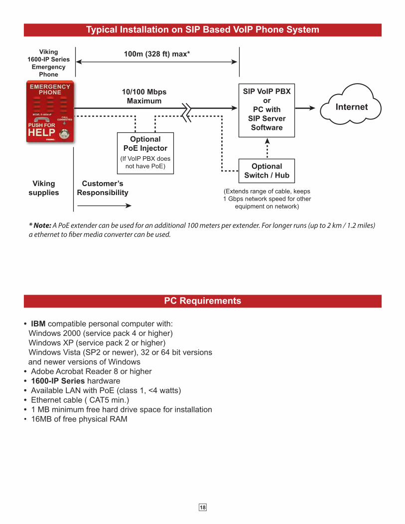
Typical Installation on SIP Based VoIP Phone System
OptionalPoE Injector
(If VoIP PBX does not have PoE) Optional
Switch / Hub
(Extends range of cable, keeps 1 Gbps network speed for other
equipment on network)
SIP VoIP PBXor
PC withSIP ServerSoftware
100m (328 ft) max*
Viking supplies
Customer’s Responsibility
Internet
10/100 MbpsMaximum
Viking1600-IP Series
EmergencyPhone
* Note: A PoE extender can be used for an additional 100 meters per extender. For longer runs (up to 2 km / 1.2 miles) a ethernet to fiber media converter can be used.
PC Requirements
• IBM compatible personal computer with:
Windows 2000 (service pack 4 or higher)
Windows XP (service pack 2 or higher)
Windows Vista (SP2 or newer), 32 or 64 bit versions
and newer versions of Windows
• Adobe Acrobat Reader 8 or higher
• 1600-IP Series hardware
• Available LAN with PoE (class 1, <4 watts)
• Ethernet cable ( CAT5 min.)
• 1 MB minimum free hard drive space for installation
• 16MB of free physical RAM

19
PC Programming
A DVD is included with each 1600-IP Series VoIP phone. The DVD contains the application “Viking VoIP Phone
Programming” used to program the unit using a PC running Windows 2000, XP, Vista, Windows 7, or Windows 8 (see
System Requirements above). The PC must be connected to the same LAN as the 1600-IP VoIP phone. Install the application
on your PC by placing the DVD into your PC’s drive. Click “I Accept” on the bottom of the first screen, then select “Viking
VoIP Phone Programming” and click the “Install” button. Follow the directions on the screen. If you are reinstalling the Viking
VoIP Phone Programming software you must uninstall the original version first via “Add and Remove Programs”. To start
the Viking VoIP Phone Programming application, click on the Viking VoIP Phone Programming icon on your desk top. The
Main screen will appear, allowing the user to program any 1600-IP phone connected to that LAN.
B. Configuring the 1600-IP Series Network Settings
Step 1.Open the “Viking VoIP Phone Programming” software on a windows PC that is connected to the same LAN as the 1600-IP phone to be
programmed.
Step 2.The window in the upper left corner of the menu will show you each 1600-IP phone that is connected to that LAN. Select the unit with
the same MAC address shown on the label located on the top of the Ethernet connector on the 1600-IP phone.
Step 3. Click the “Connect” button. If a pop up window appears, enter the unit’s security code (factory set to 845464) then click the “OK” button.
Step 4. The program will then read and display the 1600-IP phone’s IP and programming settings.
Step 5.After adjusting the IP and phones settings, click the “Write” button under each column of settings to send the programming commands
to the connected unit.
A. Manually Muting SIP/Network Failure Alarm Beeps (3 beeps repeated every 30 seconds)
With the unit connected and powered (Green LED on and Yellow LED off or blinking) it will output 3 beeps every 30
seconds and turn the Call/Call Connected LED on and off once per second indicating a SIP registration failure, failure
to receive an echo reply from a pinged gateway or Ethernet connection failure. You can manually disable the beeps by
pressing and holding the Call button for 5 seconds (2 beeps will then be heard) or by clicking the “Mute Alarm Until
Next Failure” tab in the Viking VoIP programming software. The LED will continue to flash allowing you to trouble shoot
the failure.
20
C. Manually Resetting All Network Parameters to Factory Default
Touch Tone Programming
Step 1. Power down the 1600-IP Series phone by disconnecting the RJ45 plug.
Step 2. Press and hold the HELP/CALL button, then reconnect the RJ45.
Step 3.
Continue to hold the button until you hear 2 beeps, (approximately 6 seconds). Continue to hold the button until you
hear 4 more beeps, approximately 6 seconds later, then release the button. The “Call Connected” LED will remain off
for the first 3 seconds, flash slowly for 3 seconds (2 beeps), fast flash for 6 seconds (4 beeps), then light steady
indicating when to release button.
Step 4.The unit should continue to output double beeps and slowly flash the LED indicating all Network Parameters are now
reset to factory default. The default static IP Address is: 192.168.154.1
Step 5. You must now power cycle the unit by momentarily disconnecting the RJ45.
Step 6.You will be required to re-enter your initial network settings prior to any touch tone programming, see section B on
page 19.
A. Accessing the Touch Tone Programming Mode
1. Using the Security Code to Enter Programming
Step 1. From a touch tone phone call the 1600-IP Series phone you would like to program.
Step 2.When the 1600-IP Series phone answers, enter the 6-digit security code (factory set to 845464, see section B). A double beep
should then be heard indicating you have entered the programming mode.
Step 3. You can now touch tone program the Quick Programming Features listed on page 21.
2. Manually Resetting the Security Code to Enter Programming
Step 1. Power down the 1600-IP Series phone by disconnecting the RJ45 plug.
Step 2. Press and hold the HELP/CALL button, then reconnect the RJ45.
Step 3.Continue to hold the button until you hear 2 beeps, (approximately 6 seconds). Then release the button. The “Call Connected” LED
will remain off for the first 3 seconds, flash slowly for 3 seconds then fast flash (after 2 beeps) indicating when to release button.
Step 4. The security code is now reset to 845464 (factory default).
Step 5. You can now enter touch tone programming by following the steps in section 1. Using the Security Code, above.
The 1600-IP Series emergency phones can be programmed by calling the unit from any touch tone phone.
Step 1. Access programming as shown in Programming section A.
Step 2. Enter 123456 #19.
Step 3. Hang-up.
B. Security Code (#19)
The security code allows the user/installer to program
the 1600-IP Series phone. The factory set security
code is 845464 (V-I-K-I-N-G). It is recommended that
the factory set security code be changed.
Note: The security code must be 6 digits and cannotinclude a Q or a #.
Example: To store 123456 as the security code (shown
below).

21
Quick Programming Features (after accessing the Touch Tone Programming Mode)
DESCRIPTION DIGITS +MEMORY
LOCATION
First emergency speed dial number 0-32 digits then #00
Second emergency speed dial number 0-32 digits then #01
Third emergency speed dial number 0-32 digits then #02
Fourth emergency speed dial number 0-32 digits then #03
Fifth emergency speed dial number 0-32 digits then #04
First “Info” speed dial number (E-1600-20/22/52/53-IP only) 0-32 digits then #05
Second “Info” speed dial number (E-1600-20/22/52/53-IP only) 0-32 digits then #06
Third “Info” speed dial number (E-1600-20/22/52/53-IP only) 0-32 digits then #07
Fourth “Info” speed dial number (E-1600-20/22/52/53-IP only) 0-32 digits then #08
Fifth “Info” speed dial number (E-1600-20/22/52/53-IP only) 0-32 digits then #09
To clear any speed dial number (no digits) then #00 - #09
Talk/Listen Delay (VOX) (.1 to .9 sec, factory set to .5 sec) 1 digit (1-9) then #11
Call Length Time Out (0 to 9 min, 0 = disabled, factory set to 3 min) 1 digit (0-9) then #12
Repeat Announcement (0 to 9, 0 = play every 6 sec, factory set to 1) 1 digit (0-9) then #15
Lap Counter (0 to 9, 0 = disabled, factory set to 0) 1 digit (0-9) then #16
Dial Next Number on Ring No Answer (0 or 1 = disabled, 2 - 9 = number of rings, factory set to 7) 1 digit (0-9) then #17
Dial Next Number on Busy (0 or 1, 0 = disabled, factory set to 1/enabled) 1 digit (0 or 1) then #18
Security code (factory set to 845464) 6 digits (0-9) then #19
Identification number (1-6 digits, blank = disabled, factory set to 987654) 0-6 digits (0-9) then #20
Access Code (1-6 digits, blank = disabled, factory set to 123456) 0-6 digits (0-9) then #21
Microphone volume (0-9, 0 = ANC, factory set to 5) 1 digit (0-9) then #22
Speaker Volume (0-9, factory set to 5) 1 digit (0-9) then #23
Relay Activation Command ( 1 or 2 digits, QQQQ = QQ, Q#Q# = ##, 0-9 or 00-99, factory set to QQ) (Relay Mode must be set to 0 = Door Strike)
1 or 2 digits then #24
Relay Activation Time (2 digits, 00-99 sec, 00= 0.5 sec, factory set to 05) 2 digits (00-99) then #25
Relay Mode (0 = Door Strike, 1 = Outbound Call, 2 = In/Outbound Call, 3 = Doorbell, 4 = LV-1K Control,
factory set to 1)1 digit (0-4) then #26
Relay Activation Tone (Buzz) Volume (1 digit 0-3, 0 = off, factory set to 3) 1 digit (0-3) then #27
In-Band Audio Detection Sensitivity (1-9, 1 = minimum, 9 = maximum, factory set to 5, power cycle unit after setting) 1 digit (1-9) then #28
In-Band Audio Call Progress Detection (0 or 1, 0 = OFF, 1 = ON, factory set to 0) 1 digit (0 or 1) then #29
“Call Connected” LED Control (0 or 1, 0 = Automatic, 1 = Called Party Control / Q entered to light LED, factory set to 0) 1 digit (0 or 1) then #30
Speaker Mode (0, 1 or 2, 0 = OFF/Silent Monitor, 1 = ON, 2 = OFF Until Answered, factory set to 1) 1 digit (0-2) then #31
LED Mode (1 digit 0-3, 0 = OFF, 1 = Entry Phone, 2 = Emergency Phone, 3 = Emergency Phone Outbound
Only, factory set to 2)1 digit (0-3) then #32
Auto Answer / Loud Ring (0, 1 or 2, 0 = Disabled, 1 = Auto Answer, 2 = Loud Ring, 3 = Loud Ring with AGC,
factory set to 1)1 digit (0-3) then #33
DESCRIPTION ENTER DIGITS
Diagnostic tones (used to check mic and speaker operation) Q0
Enable Alternate Switch Action (factory setting) Q1
Disable Alternate Switch Action Q2
Erase Message Q3
Record Message (enter # to stop recording) Q4
Playback Message Q5
Enable Relay Latching Commands (factory setting) Q6
Disable Relay Latching Commands Q7
To add a Q at any point in the dialing string or relay command QQ
To add a # at any point in the dialing string or relay command Q#
Reset all Quick Programming Features to factory default settings ###

22
Programming Features
To Program the 1600-IP Series Phone... Step 1 Step 2
...to store 555-1234 as the first emergency speed dial number
Enter Programming
(see A. Accessing the Touch Tone
Programming Mode, page 20)
Enter digits:
5 5 5 1 2 3 4 # 0 0
...to clear the first emergency speed dial number
Enter Programming
(see A. Accessing the Touch Tone
Programming Mode, page 20)
Enter digits:
# 0 0
A. Emergency Speed Dial Numbers (memory locations #00 - #04)
1. Speed Dial Numbers (#00 - #09)
Note: Up to 32 digits can be stored in each dial position via touch tone programming, up to 90 characters via PC programming. Touchtone Q and # count as single digits.
The emergency speed dial number programmed in location #00 is the number that is dialed when the “HELP” /
”CALL” button is first pressed. Additional speed dial numbers will be dialed when there is no answer or a busy
signal is detected and the next number redial features are activated. To program, enter the desired speed dial
number followed by the location number (#00 - #04). To clear a speed dial location, simply enter the memory
location (#00 - #04) alone. The 1600-IP Series phone is factory set with no speed dial number programmed.
To Program: Enter:
Q QQ
# Q#
0, 1, 2 .... 9 0, 1, 2 .... 9
B. “INFO” Speed Dial Numbers (E-1600-20/22/52/53-IP only) (memory locations #05 - #09)
The information speed dial number programmed in location #05 is the telephone or extension number that is dialed when the “INFO” button is first
pressed (E-1600-20/22/52/53-IP). Additional information speed dial numbers will be dialed when there is no answer and the next number redial
feature is activated. The 1600-IP Series phone will cycle through the programmed speed dial numbers until answered. To program, enter the
desired speed dial number followed by the location number (#05 - #09). To clear a speed dial location, simply enter the location (#05 - #09) alone.
C. Speed Dial Programming Examples
This feature selects switching time between talk and listen modes (VOX switching time). Use chart
at the right.
* Note: The factory default is .5 seconds.
2. Talk / Listen Delay (VOX) (#11)
This feature selects the maximum length of time that calls can be connected. Programmable in
increments of 1 minute up to a maximum of 9 minutes (Touch Tones 1 - 9). Program 0 in this location
to disable the call length time out. With the call length disabled, the 1600-IP Series phone must rely
on a CPC signal, busy signal, silence or return to dial tone to hang-up. Use chart at the right.
* Note: The factory default is 3 minutes.
3. Call Length Time Out (#12)
Touch
Tone
Talk/Listen
Delay
1 .1 sec
2 .2 sec
3 .3 sec
4 .4 sec
5 .5 sec *
6 .6 sec
7 .7 sec
8 .8 sec
9 .9 sec
Touch
Tone
Call Length
Time Out
0 Disabled
1 1 min
2 2 min
3 3 min*
4 4 min
5 5 min
6 6 min
7 7 min
8 8 min
9 9 min

23
5. Lap Counter (#16)
6. Dial Next Number on Ring No Answer (#17)Touch
Tone
Ring No
Answer
0 Disabled
1 1 ring
2 2 rings
3 3 rings
4 4 rings
5 5 rings
6 6 rings
7 7 rings*
8 8 rings
9 9 rings
Touch
Tone
Lap
Counter
0 Disabled*
1 1 time
2 2 time
3 3 time
4 4 time
5 5 time
6 6 time
7 7 time
8 8 time
9 9 time
The 1600-IP Series phone can be programmed to play the announcement from 1-9 times,
or to continuously repeat the announcement every 6 seconds until a Touch Tone Q is detectedfrom the distant party. The call connected LED will turn on automatically after the
announcement has stopped repeating.
* Note: The factory default for the 1600-IP Series phone is to play the voice announcementone time.
4. Repeat Announcement Option (#15) Touch
Tone
Repeat
Announcement
0 Repeat every 6 seconds
1 1 time*
2 2 time
3 3 time
4 4 time
5 5 time
6 6 time
7 7 time
8 8 time
9 9 time
With the lap counter disabled (factory setting), if the 1600-IP Series phone is programmed to dial the
next number on ring-no-answer and/or busy signal (see section 6 and 7 below), the 1600-IP Series
phone will continuously call its programmed phone numbers forever until the call is answered.
The lap counter is a programmable counter that determines how many times the 1600-IP Series phone
will cycle through its list of up to 5 emergency numbers (or up to 5 “Info” phone numbers), before it
stops the dialing process and hangs up. When all of the programmed phone numbers have been
dialed, the lap counter is incremented and the dialing process repeats. When the lap counter has been
met, the dialing process stops and the 1600-IP Series phone hangs up.
* Note: This feature is disabled in the factory default setting.
If enabled and a ring-no-answer is detected, the 1600-IP Series phone will dial the next programmed
speed dial number, and continue to cycle through the emergency numbers until a call is completed.
* Note: Factory set to redial if not answered after 7 rings.
If enabled and a busy is detected, the 1600-IP Series phone will dial the next programmed
speed dial number, and continue to cycle through the numbers until a call is completed.
7. Dial Next Number on Busy (#18)
* Notes: This feature is enabled in the factory default setting. If the busy signal is interrupted with a promotional message, contactyour central office to have it removed.
Touch Tone Dial on Busy
0 Disabled
1 Enabled*
The Touch Tone I.D. number (up to 6 digits) is used by emergency personnel to identify the location of the caller and is given out
when the receiving party presses a Touch Tone Q. The security office can display the number using a Touch Tone decoder. Toprogram the I.D. number, enter the desired number followed by #20. Example: To store 333 as the I.D. number, enter: 3 3 3 # 2 0
8. Identification Number (#20)
The Access Code is used for remotely operating the relay (Doorstrike, Mag-Lock, etc) by calling into the unit. This code provides
basic security and only allows operation of the relay and not the ability to change any of the programming parameters. Once entered,
any of the “Remote Access Operation Commands” can be used. The code can be 1 to 6 digits in length and cannot contain a “Q”, “#”or match the numbers used for the security code. To disable the Access Code enter no digits then #21 in programming. Simply call
the 1600-IP Series phone, the unit will automatically answer the line and output two beeps. You then enter the programmed 1 to 6
digit access code, 2 beeps should be heard. You can now enter any “Remote Access Operation Commands” (see page 26).
9. Access Code (#21)

24
The microphone volume can be set from 1 to 9 (1 = lowest volume setting, 9 = the highest, factory set to 5) by entering the single
digit then the memory location #22. Alternatively the microphone can be placed in the “ANC” Automatic Noise Cancelling mode by
entering 0#22 in programming. With the mic in the ANC mode, when background noise increases, the mic gain will automatically
decrease. When background noise decreases the mic gain will automatically increase. The ANC mode is useful in applications where
the background noise level can change drastically such as a gas car running vs a diesel truck.
10. Microphone Volume/Automatic Noise Cancelling Mode (#22)
The speaker volume can be set from 0 to 9 (0 = lowest volume setting, 9 = the highest, factory set to 5) by entering the single digit
then the memory location #23. Alternatively the speaker can be turned off for silent monitoring by entering 0#31 (see Speaker Mode
section 19).
11. Speaker Volume (#23)
The one or two digit code stored in the Relay Activation Command is the touch tone command that the person being called must
enter on their phone in order to actuate the relay (door strike/mag-lock/gate controller, etc). The code can contain the numbers 0 - 9,
00 - 99, ## or QQ (factory default). The code must not match the first 1 or 2 digits of the security code. To program the code to “##”
you must enter Q#Q# #24 in programming. To program the code to “QQ” you must enter QQQQ #24 in programming. To disable thisfeature enter #24 without any preceding digits. The code must be entered while the remote phone is communicating with the
Emergency/Entry phone. The Emergency/ Entry phone determines which direction the touch tone is coming from and only responds
to touch tones from the called phone.
12. Relay Activation Command (#24)
The value stored in the Relay Activation Time is the amount of time the relay will be energized after a correct touch tone command
is entered. This two digit number can range from 01 to 99 seconds, or enter 00 for 0.5 seconds. The factory setting is 5 seconds.
13. Relay Activation Time (#25)
The 2 amp relay contacts can be programmed to one of five different modes by entering 0,1,2,3 or 4 #26 in programming.
0 = Doorstrike Mode. When programmed for Doorstrike Mode the relay will momentarily activate for the preprogrammed relay activation time after
detecting the correct relay activation command (one or two digit touch tone) from the called party.
1 = Outbound Call Mode. When programmed for Outbound Call Mode the relay will activate continuously for the duration of any outbound call from
the Emergency/Entry phone. This mode is useful for activating strobe lights for Emergency VoIP phones.
2 = Inbound/Outbound Call Mode. When programmed for Inbound/Outbound Call Mode the relay will activate continuously for the duration of any
inbound or outbound call to or from the Emergency/Entry phone. This mode is useful for turning on IR flood lights, for VoIP phones with cameras, etc.
3 = Doorbell Mode. When programmed for Doorbell Mode the relay will momentarily activate the relay for the preprogrammed relay activation time
on any outbound call from the Emergency/Entry phone. This mode is useful for activating a door chime, etc. When activating door chimes, a 0.5 - 1
second relay activation time is recommended.
4 = LV-1K Control Mode. When programmed for LV-1K Control Mode the relay will activate continuously while the Emergency/Entry phone is powered
and registered to the SIP server. In the event the unit loses power and/or SIP registration the relay will turn off, activating LV-1K’s flashing LED and
audible beep signals.
5 = Loud Ring Mode. When programmed for Loud Ring Mode the relay will continuously activate while the ringing extension is called. This mode is
useful for activating a Viking model SL-2 strobe light, etc.
6 = Loud Ring Flash Mode. When programmed for Loud Ring Flash Mode the relay will momentarily turn on and off in a 400ms on/off cadence while
the ringing extension is called. This mode is useful for activating a Viking LPL-1 Remote Visual Indicator, etc.
14. Relay Mode (#26)
The relay activation tone is a buzzing sound that is heard at the Emergency/Entry phone when the door strike relay is activated. After
the called party enters the correct relay activation command, the called party will hear 2 short confirmation beeps and the Emergency
phone will output a buzzing sound(realy activation tone) while the door strike relay is activated.The tone (buzz) length will match the
relay activation time up to a maximum of 5 seconds. The tone (buzz) can be programmed to three different volume settings 1 = Low,
2= Medium, 3 = High in memory location #27. The tone can also be turned off/disabled by entering 0#27.
15. Relay Activation Tone (Buzz) Volume (#27)
The In-Band Audio Detection Sensitivity can be set from 1 to 9 (1 = minimum setting, 9 = the highest, factory set to 5) by entering the
single digit then the memory location #28. Increasing or decreasing the sensitivity may be required in applications where you are
making an outbound call through your VoIP phone system and are relying on In-Band analog audio detection of the distant party
answering to turn on the call connected LED and/or play the location ID message on Emergency VoIP phones. NOTE: Power cycling
the unit is required after touch tone programming this feature.
16. In-Band Audio Detection Sensitivity (#28)
The In-Band Audio Call Progress Detection can be set to 0 or 1 (0 = OFF, 1 = ON, factory set to 0) by entering the single digit then
the memory location #29. In-Band Audio Call Progress detection should be turned ON in applications where you are making an
outbound call through your VoIP phone system and are relying on In-Band analog audio detection of the distant party answering to
turn on the call connected LED and/or play the location ID message on Emergency VoIP phones.
17. In-Band Audio Call Progress Detection (#29)

25
The Auto Answer/Loud Ring feature can be set to one of four modes.
0 = Disabled: In the “Disabled” mode the phone will not automatically answer an incoming call. CAUTION: In the “Disabled” mode, touch toneprogramming will not be possible.1 = Auto Answer (factory setting): In the “Auto Answer” mode the phone will automatically answer an incoming call on the first ring.
2 = Loud Ring: In the “Loud Ring” mode the phone will not automatically answer an incoming call but will output a loud ring signal out of the speaker
in a 2 seconds on, 4 seconds off ring pattern. The call can then be answered by pressing the button.
3 = Loud Ring with AGC: In the “Loud Ring with AGC” mode the phone will not automatically answer an incoming call but will output a loud ring
signal out of the speaker in a 2 seconds on, 4 seconds off ring pattern. The phone will automatically increase or decrease the ring volume based on
background ambient noise. The call can then be answered by pressing the button.
21. Auto Answer / Loud Ring (#33)
Step 1. Call into the 1600-IP Series phone with a Touch Tone phone and access programming.
Step 2. Enter Q4, wait for the tone and then begin recording (28 seconds of record time is available).
Step 3. Enter # to stop the recording. Playback is automatic.
Step 4. Enter Q5 to review the announcement again.
Step 5. If you choose to not use a voice announcement, enter Q3 to clear the recording.
Example: “Elevator number 1215, located in the Financial Building, needs assistance. Press the star (Q) key on your telephone tohear this announcement again.”
With “Q1” (factory default) programmed the HELP/CALL button alternately connects and disconnects calls. With “Q2” programmedthe HELP/CALL button connects calls only. Pressing the button again after the call has been initiated will not terminate the call.
22. Enable/Disable Alternate Switch Action (Q1, Q2)
23. Recording the Announcement
With “Q6” (factory default) programmed the Remote Access Operation Commands (Q0 and Q1) to Un-Latch or Latch the relay areenabled.
With “Q7” programmed the Remote Access Operation Commands (Q0 and Q1) to Un-Latch or Latch the relay are disabled. Disablingthe Latch commands can be useful in applications where you want to eliminate the possibility of inadvertently entering a latch
command leaving a gate open/closed, etc.
24. Enable/Disable Relay Latching Commands (Q6, Q7)
Entering ### in programming will reset all of the Quick Programming Features back to their factory default settings. Note: The ###command will not change or reset your IP settings.
25. Reset All Quick Programming Features (###)
The “Call / Call Connected” LED can be programmed to one of four different modes: 0/OFF, 1/Entry Phone, 2/Emergency Phone (factory setting) or
3/Emergency Phone Outbound Only.
0 = OFF Mode: Useful for silent monitoring applications. In this mode the LED will not light during normal operation. It will only light (blink) if it cannot
register with the programmed SIP server or while manually resetting all network parameters to factory default.
1 = Entry Phone Mode: The LED will remain ON in the idle state, turn off while button is pressed, blink during dialing, light steady when the call is
answered, then turn OFF momentarily when the call is completed.
2 = Emergency Phone Mode: The LED will remain OFF in the idle state, blink during dialing, light steady when the call is connected, then turn OFF
when the call is completed.
3 = Emergency Phone Outbound Only: On outbound calls, the LED will remain OFF in the idle state, blink during dialing, light steady when the call
is connected, then turn OFF when the call is completed. On in-bound calls, the LED will remain off. This is useful for silent monitoring on inbound calls.
20. LED Mode (#32)
The call connected LED on the 1600-IP Series phone can be programmed to:
0 = LED will automatically light when the distant party has answered, this is the factory default setting.
1 = LED will light steady, only after a Touch Tone Q is entered from the called party.
18. “Call Connected” LED Control (#30)
The Speaker Mode can be set to one of three modes.
0 = OFF/Silent Monitoring Mode: In the “OFF” mode the speaker is disabled at all times. However, the speaker can be enabled after
communication has been established by entering touch tone command “9#”. The speaker will remain on for the duration of the call.
1 = ON (factory setting): In the “ON” mode the speaker is enabled during In-bound and Out-bound calls.
2 = OFF Until Answered: In the “OFF Until Answered” mode the speaker will remain silent during dialing and will not turn on until
the called party has answered.
19. Speaker Mode (#31)

26
Troubleshooting
If the unit cannot register with the programmed SIP server, the LED will blink on and off every two seconds, and three error
beeps will be heard every 30 seconds until communication is restored. This alerts a potential user of a problem with the
device that will prevent an emergency phone call from being made.
You may silence the error beeps, per instance, by pressing and holding the HELP/CALL button for 5 seconds or by clicking
the “Mute Alarm Until Next Failure” button in the Viking VoIP Programming Software (see section A on page 19). The error
beeps automatically re-enable once the unit is registered, to alert of any new problems that arise.
Operation
A. “HELP” / “CALL” Button
When the “HELP” / “CALL” button is pressed, the 1600-IP Series phone dials a pre-programmed telephone number. The Call
Connected LED momentarily flashes during dialing. In the event the line is busy or there is a ring-no-answer, the unit can be
programmed to call additional phone numbers.
The phone then cycles through up to 5 pre-programmed emergency numbers until the call is answered. When the call is answered,
the digital voice announcer will automatically play to identify the location of the emergency call. The phones are factory programmed
to play the announcement once, and then automatically light the “Call Connected” LED to show that handsfree communication to
emergency personnel is established. The Q key will send the I.D. number (if programmed), and play the announcement again. Thedistant party will know the location of the emergency call by either the voice announcement or by decoding the Touch Tone I.D.
number. Once the “Call Connected” LED is on, the # key can be used to force the phone to hang-up.
B. “INFO” Button (E-1600-20/22/52/53-IP)
When the “INFO” button is pressed (E-1600-20/22/52/53-IP only), the phone goes off-hook and dials the first “INFO” phone number
programmed. If a busy signal is detected or the call goes unanswered, the phone will cycle through all five “INFO” phone numbers
until the call is answered. When answered, handsfree communication is established. Note: The voice announcement is forEmergency/Help calls only and will not play on a call initiated from the “INFO” button.
C. Remote Access Operation Commands
FeatureTone Tone
CommandDescription
Activate
RelayQQ or
___ ___Momentarily activate relay (1 or 2 digits, factory set to QQ).
Un-Latch
RelayQ0 Un-latch* (deactivate) the relay.
Latch
RelayQ1 Latch* (continuously activate) the relay.
Disconnect # Disconnects or forces the emergency phone to hang up.
Send ID and
Play MessageQ Send I.D. number (if programmed) and plays the announcement.
* Note: Latching commands must be enabled (Q6) in programming.
The following commands can be entered after answering an inbound call from the emergency phone. The commands can also be
entered on an outbound call to the emergency phone. After the emergency phone auto answers the call, two beeps will be heard. If
the access code has been disabled, you can now enter the Remote Access Operation Commands below. If an Access code has been
programmed, enter the Access code digits. With the correct code entered, two beeps will be heard and you can now enter the Remote
Access Operation Commands below.

27
Related Products
New ASME A17.1-2010 code requires that “the two-way communications means within
the (elevator) car shall include a means to verify operability of the LAN connection”. When
your local municipality adopts this new ASME A17.1 code the LV-1K can be added to
fulfill all requirements for visual and audible signaling when it is determined the LAN
connection is not functioning.
The LV-1K can be added to any new or existing Viking 1600-IP Series elevator
emergency phone as a stand alone solution. The LV-1K continuously monitors for loss
of PoE or communication with the server and will immediately provide an audible and
visual indication when the LAN connection has been accidentally cut or disconnected.
In accordance to ASME A17.1, the LV-1K is labeled “ELEVATOR COMMUNICATION
FAILURE” in ¼” high red letters, and will sound an audible signal every 30 seconds and
flash a red light when a loss of connection is detected. Authorized personnel can silence
the audible signal with the included key switch. The LED will remain flashing until the
fault is corrected.
Line Verification Panel with Key Switch
For more information, see DOD 246
The VE-3x5, VE-5x5, VE-6x7 and VE-5x10 add vandal and weather resistance, as well as
versatility to many Viking products. The VE-Series backboxes are available in black fine texture
powder painted steel or Marine Grade 316 stainless steel. The weather resistant boxes are
designed to be surface mounted to a wall, post, single gang box, or a VE-GNP gooseneck
pedestal. Note: The VE-3x5 is not compatible with the VE-GNP pedestals and is not available instainless steel.
The VE-3x5 is designed to be used with the E-40-EWP or E-50-EWP Series entry
phones. The VE-5x5 is designed to be used with the E-10A-EWP, E-30-EWP,
E-30-PT-EWP, E-60-EWP, E-65-EWP, E-70-EWP, E-75-EWP entry phones, the
E-1600-20A-EWP, E-1600-20-IP-EWP, E-1600-30A-EWP and E-1600-30-IP-EWP
emergency phones, as well as the W-1000-EWP and W-3000-EWP handsfree
doorboxes. The VE-6x7 is designed to be used with the K-1700-3-EWP and
K-1705-EWP entry phones and the VE-5x10 is designed to be used with the
K-1900-7-EWP and the K-1900-8-EWP vandal resistant phones.
The VE-GNP gooseneck pedestals are designed to
be used with the VE-5x5, VE-6x7 and VE-5x10
backboxes and are ideal for drive up
communications. Note: The VE-3x5 is notcompatible with the VE-GNP pedestals. The VE-PNL’s are VE-Series backboxes with a blank aluminum panel. The user can customize
the clear-coated aluminum panel to mount an PRX-1 card reader, PRX-2 keypad or switch. The kits come complete with box, gasket,
panel and screws. Model numbers that end with “SS” are stainless steel version. Note: The use of magnets to mount the VE-Seriesenclosure to a metal surface can affect the operation of the enclosed product.
VE-3x5 VE-5x5
VE-5x10VE-5x10-NR
VE-5x10-SS-NR
VE-5x5-PNL-SS
VE-6x7-PNL-SSVE-6x7-PNLVE-6x7-SSVE-6x7
VE-5x10-PNL-SSVE-5x10-SS
VE-5x5-SSVE-5x5-RD
VE-5x10-PNL
VE-5x5-PNL
VE
-GN
P-2
VE
-GN
P-I
G
VE
-GN
P-S
S
VE
-GN
P
For more information, see DOD 424
Surface or Pedestal Mount Viking Products WhileMaintaining Weather and Vandal Resistance

28
Viking Area of Refuge Signs Designed to Comply with IBC, ADA, NFPA and ICC Requirements
The ARS Series Area of Refuge Signs are designed comply with IBC 1007,1011, ADA 4.3.11, NFPA 22, 101 and ICC 703 code
requirements. The ARS-LR100 is an LED Illuminated edge-lit double sided hanging Sign. It is AC powered with 3 hour battery backup.
The unit can be ceiling mounted, mounted flat against a wall or end mounted so it can be viewed from either direction. The Instructional,
Tactile and Directional signs are made from Acrylic or durable ABS plastic and are designed to adhere to the wall with the provided double
sided foam tape. For more information, see DOD 235.
ARS-TB100
Tactile Blue Braille and
raised letter sign to be
placed next to the Area Of
Refuge (stairwell exit) door.
ARS-IB100
Instructional Blue Braille and
Raised letter sign to be placed
next to the Area of Refuge emer-
gency phone (E-1600A-IP, etc.)
ARS-LR100
Lighted double sided Wall or ceiling
mount sign to be placed above the
Area Of Refuge (stairwell exit) door.
Directional Blue signs with left or
right arrow to be placed next to
exit doors without Area Of
Refuge.
ARS-DLB100
ARS-DRB100
• ARS-LR100: Red LED edge lit wall sign, 120/277V AC power, Included
NiCad battery delivers over 3 hours of battery backup, UL listed,
Universal wall, side or ceiling mounting, Silver aluminum housing with
mirrored double sided acrylic sign surface, Battery test button, AC pwr
LED, Low voltage automatic battery disconnect to prevent deep cycling
battery, mounting hardware and 4 optional Chevron arrows with
mounting templates included.
• ARS-TB100: 6” wide x 9” tall Tactile Sign with 0.031” raised white
letters and accesability symbol, California compliant Contrated Grade 2
Braille. Blue PMS 300 Acrylic with non-glare finish, 0.032” thick double
sided foam included.
• ARS-IB100: 6” wide x 7.5” tall Instructional sign with 0.031” raised
white “Push For Help” letters and ingraved white text, California
compliant Contrated Grade 2 Braille. Blue PMS 294 ABS with non-glare
finish, 0.032” thick double sided foam included.
• ARS-DLB100 (left arrow) and ARS-DRB100 (right arrow): 12” wide x 4”
tall Directional sign with ingraved white text, Blue PMS 294 ABS with
non-glare finish, 0.032” thick double sided foam included.
• VE-ARSW: Area of Refuge surface mount command center cabinet.
Lockable for mounting “Two-Way Communications System” phone in
low rise (less than 60 ft tall) buildings. See DOD 237.
Emergency Phone Panic Button Kit(for use with Viking Emergency Phones)
The PB-1 Panic Button Kit connects to a Viking 1600A or
1600-IP Series Emergency Phone to provide a one-way
talk path to the pre-programmed number when used.
The PB-1 will activate the 1600A or 1600-IP Series
Emergency Phone and allows the called party to light a red
LED to indicate that the call is connected. The called party
will be able to hear the installation site, but the site will not
be able to hear the called party. This makes it a very
effective security measure, as there is no other indication
that the site is being monitored.
For more information, see DOD 233

29
Printed in the U.S.A ZF303600 REV B
Due to the dynamic nature of the product design, the information contained in this document is subject to change without notice. Viking Electronics, and its affiliates and/or subsidiaries
assume no responsibility for errors and omissions contained in this information. Revisions of this document or new editions of it may be issued to incorporate such changes.
DOD 255
Warranty
Product Support: 715-386-8666
IF YOU HAVE A PROBLEM WITH A VIKING PRODUCT, CONTACT: VIKING TECHNICAL SUPPORT AT 715-386-8666
Our Technical Support Department is available for assistance Monday through Friday 8:00am to 5:00pm central time. So that we can give you better
service, before you call please:
1. Know the model number, the serial number and what software version you have (see serial label).
2. Have your Product Manual in front of you.
3. It is best if you are on site.
RETURNING PRODUCT FOR REPAIRThe following procedure is for equipment that needs repair:
1. Customer must contact Viking's Technical Support Department at 715-386-8666 to obtain a Return Authorization (RA) number. The customer MUST
have a complete description of the problem, with all pertinent information regarding the defect, such as options set, conditions, symptoms, methods to
duplicate problem, frequency of failure, etc.
2. Packing: Return equipment in original box or in proper packing so that damage will not occur while in transit. Static sensitive equipment such as a
circuit board should be in an anti-static bag, sandwiched between foam and individually boxed. All equipment should be wrapped to avoid packing mate-
rial lodging in or sticking to the equipment. Include ALL parts of the equipment. C.O.D. or freight collect shipments cannot be accepted. Ship cartons
prepaid to: Viking Electronics, 1531 Industrial Street, Hudson, WI 54016
3. Return shipping address: Be sure to include your return shipping address inside the box. We cannot ship to a PO Box.
4. RA number on carton: In large printing, write the R.A. number on the outside of each carton being returned.
RETURNING PRODUCT FOR EXCHANGEThe following procedure is for equipment that has failed out-of-box (within 10 days of purchase):
1. Customer must contact Viking’s Technical Support at 715-386-8666 to determine possible causes for the problem. The customer MUST be able to
step through recommended tests for diagnosis.
2. If the Technical Support Product Specialist determines that the equipment is defective based on the customer's input and troubleshooting, a Return
Authorization (R.A.) number will be issued. This number is valid for fourteen (14) calendar days from the date of issue.
3. After obtaining the R.A. number, return the approved equipment to your distributor, referencing the R.A. number. Your distributor will then replace the
Viking product using the same R.A. number.
4. The distributor will NOT exchange this product without first obtaining the R.A. number from you. If you haven't followed the steps listed in
1, 2 and 3, be aware that you will have to pay a restocking charge.
TWO YEAR LIMITED WARRANTYViking warrants its products to be free from defects in the workmanship or materials, under normal use and service, for a period of two years from the date of purchase
from any authorized Viking distributor. If at any time during the warranty period, the product is deemed defective or malfunctions, return the product to Viking Electronics,Inc., 1531 Industrial Street, Hudson, WI., 54016. Customer must contact Viking's Technical Support Department at 715-386-8666 to obtain a Return Authorization (R.A.)number.
This warranty does not cover any damage to the product due to lightning, over voltage, under voltage, accident, misuse, abuse, negligence or any damage caused byuse of the product by the purchaser or others. This warranty does not cover non-EWP products that have been exposed to wet or corrosive environments. This warrantydoes not cover stainless steel surfaces that have not been properly maintained.
NO OTHER WARRANTIES. VIKING MAKES NO WARRANTIES RELATING TO ITS PRODUCTS OTHER THAN AS DESCRIBED ABOVE AND DISCLAIMS ANY EX-PRESS OR IMPLIED WARRANTIES OR MERCHANTABILITY OR FITNESS FOR ANY PARTICULAR PURPOSE.
EXCLUSION OF CONSEQUENTIAL DAMAGES. VIKING SHALL NOT, UNDER ANY CIRCUMSTANCES, BE LIABLE TO PURCHASER, OR ANY OTHER PARTY,FOR CONSEQUENTIAL, INCIDENTAL, SPECIAL OR EXEMPLARY DAMAGES ARISING OUT OF OR RELATED TO THE SALE OR USE OF THE PRODUCT SOLDHEREUNDER.
EXCLUSIVE REMEDY AND LIMITATION OF LIABILITY. WHETHER IN AN ACTION BASED ON CONTRACT, TORT (INCLUDING NEGLIGENCE OR STRICT LIABILITY)OR ANY OTHER LEGAL THEORY, ANY LIABILITY OF VIKING SHALL BE LIMITED TO REPAIR OR REPLACEMENT OF THE PRODUCT, OR AT VIKING'S OPTION,REFUND OF THE PURCHASE PRICE AS THE EXCLUSIVE REMEDY AND ANY LIABILITY OF VIKING SHALL BE SO LIMITED.
IT IS EXPRESSLY UNDERSTOOD AND AGREED THAT EACH AND EVERY PROVISION OF THIS AGREEMENT WHICH PROVIDES FOR DISCLAIMER OF WAR-RANTIES, EXCLUSION OF CONSEQUENTIAL DAMAGES, AND EXCLUSIVE REMEDY AND LIMITATION OF LIABILITY, ARE SEVERABLE FROM ANY OTHER PRO-VISION AND EACH PROVISION IS A SEPARABLE AND INDEPENDENT ELEMENT OF RISK ALLOCATION AND IS INTENDED TO BE ENFORCED AS SUCH.
If trouble is experienced with the 1600-IP Series phone, for repair or warranty information, please contact:
Viking Electronics, Inc., 1531 Industrial Street, Hudson, WI 54016 715-386-8666
WHEN PROGRAMMING EMERGENCY NUMBERS AND (OR) MAKING TEST CALLS TO EMERGENCY NUMBERS:Remain on the line and briefly explain to the dispatcher the reason for the call. Perform such tests in off-peak hours, such as early morning or late evenings.
PART 15 LIMITATIONSThis equipment has been tested and found to comply with the limits for a Class A digital device, pursuant to Part 15 of the FCC Rules. These limits are de-
signed to provide reasonable protection against harmful interference when the equipment is operated in a commercial environment. This equipment gen-
erates, uses, and can radiate radio frequency energy and, if not installed and used in accordance with the instruction manual, may cause harmful
interference to radio communications. Operation of this equipment in a residential area is likely to cause harmful interference in which case the user will
be required to correct the interference at his own expense.
CANADAThis class A digital apparatus complies with Canadian ICES-003. Cet appareil numerique de la classe A est conforme a la norme NMB-003 du Canada.