
designed for Functional Safety -...
154
item Industrietechnik GmbH Phone: +49-(0)212-6580-0 Friedenstraße 107-109 Telefax: +49-(0)212-6580-310 42699 Solingen E-mail: [email protected] Germany http://www.item24.com Product Manual item Servo Positioning Controller C 1-Series designed for Functional Safety
Transcript of designed for Functional Safety -...

item Industrietechnik GmbH Phone: +49-(0)212-6580-0
Friedenstraße 107-109 Telefax: +49-(0)212-6580-310
42699 Solingen E-mail: [email protected]
Germany http://www.item24.com
Product Manual
item Servo Positioning Controller C 1-Series designed for Functional Safety

Page 2
Translation of the original instructions
Copyrights
© 2018 item Industrietechnik GmbH. All rights reserved.
The information and data in this document have been composed to the best of our knowledge. However, deviations between the document and the product cannot be excluded entirely. For the devices and the corresponding software in the version handed out to the customer, item guarantees the contractual use in accordance with the user documentation. In the case of serious deviations from the user documentation, item has the right and the obligation to repair, unless it would involve an unreasonable effort. A possible liability does not include deficiencies caused by deviations from the operating conditions intended for the device and described in the user documentation.
item does not guarantee that the products meet the buyer’s demands and purposes or that they work together with other products selected by the buyer. item does not assume any liability for damages resulting from the combined use of its products with other products or resulting from improper handling of machines or systems.
item Industrietechnik GmbH reserves the right to modify, amend, or improve the document or the product without prior notification.
This document may, neither entirely nor in part, be reproduced, translated into any other natural or machine-readable language nor transferred to electronic, mechanical, optical or any other kind of data media, without expressive authorisation by the author.
Trademarks
Any product names in this document may be registered trademarks. The sole purpose of any trademarks in this document is the identification of the corresponding products.
item Motion Soft® is a registered trademark of item Industrietechnik GmbH.

Page 3
Revision Information
Author: item Industrietechnik GmbH
Manual title: Product Manual „item Servo Positioning Controller C 1-Series“
File name: DOK_BEDA_Steuerung-C1-Serie_#SEN_#AQU_#V1.docx
Version 5.0 July 2018

Page 4
TABLE OF CONTENTS:
1 GENERAL ............................................................................................................. 14
1.1 Documentation .............................................................................................. 14
1.2 Scope of supply ............................................................................................. 15
2 SAFETY NOTES FOR ELECTRICAL DRIVES AND CONTROLLERS ....................................... 16
2.1 Used symbols ................................................................................................ 16
2.2 General notes ................................................................................................ 17
2.3 Danger resulting from misuse............................................................................ 19
2.4 Safety notes .................................................................................................. 20
2.4.1 General safety notes ........................................................................ 20
2.4.2 Safety notes for assembly and maintenance ........................................... 22
2.4.3 Protection against contact with electrical parts ....................................... 24
2.4.4 Protection against electrical shock by means of protective extra-low voltage (PELV) .......................................................................................... 24
2.4.5 Protection against dangerous movements ............................................. 25
2.4.6 Protection against contact with hot parts ............................................... 26
2.4.7 Protection during handling and assembly .............................................. 27
3 PRODUCT DESCRIPTION .......................................................................................... 28
3.1 General ....................................................................................................... 28
3.2 Power supply ................................................................................................ 31
3.2.1 Single-phase AC supply with active PFC ................................................ 31
3.2.1.1 Behaviour during switch-on ............................................................................31
3.2.1.2 Behaviour during normal operation and control characteristics ..............................32
3.2.2 DC bus coupling, DC supply ............................................................... 33
3.2.2.1 DC bus coupling ..........................................................................................33
3.2.2.2 DC supply ..................................................................................................33
3.2.3 Mains fuse ..................................................................................... 33
3.3 Brake chopper .............................................................................................. 34
3.4 Communication interfaces ................................................................................ 34
3.4.1 Serial interface [X5] ......................................................................... 35
3.4.2 USB interface [X19] ......................................................................... 35
3.4.3 UDP interface [X18] ......................................................................... 35

Page 5
3.4.4 CAN interface [X4] ........................................................................... 35
3.4.5 Technology module: PROFIBUS .......................................................... 36
3.4.6 Technology module: EtherCAT ............................................................ 36
3.4.7 I/O functions and device control .......................................................... 36
4 TECHNICAL DATA .................................................................................................. 37
4.1 General Technical data .................................................................................... 37
4.2 Operating and display elements ......................................................................... 39
4.3 Supply [X9] ................................................................................................... 40
4.4 Motor connection [X6] ..................................................................................... 42
4.4.1 Current derating .............................................................................. 42
4.5 Motor feedback connection [X2A] ...................................................................... 47
4.5.1 Resolver connection [X2A] ................................................................. 48
4.5.2 Encoder connection [X2B] ................................................................. 48
4.6 Communication interfaces ................................................................................ 51
4.6.1 RS232 [X5] ................................................................................... 51
4.6.2 USB [X19] ..................................................................................... 51
4.6.3 Ethernet [X18] ................................................................................ 51
4.6.4 CAN bus [X4] ................................................................................. 51
4.6.5 SD/MMC card ................................................................................ 52
4.6.6 I/O interface [X1] ............................................................................. 52
4.6.7 Incremental encoder input [X10] ......................................................... 53
4.6.8 Incremental encoder output [X11] ....................................................... 54
5 FUNCTION OVERVIEW ............................................................................................. 55
5.1 Motors ........................................................................................................ 55
5.1.1 Synchronous servo motors ................................................................ 55
5.1.2 Linear motors ................................................................................. 55
5.2 Functions of the item servo positioning controller C 1-Series ..................................... 56
5.2.1 Compatibility .................................................................................. 56
5.2.2 Pulse width modulation (PWM) ........................................................... 57
5.2.3 Setpoint management ...................................................................... 57
5.2.4 Torque-controlled mode .................................................................... 58
5.2.5 Speed-controlled mode ..................................................................... 58

Page 6
5.2.6 Torque-limited speed control .............................................................. 58
5.2.7 Synchronization to the external clock signal ........................................... 58
5.2.8 Load torque compensation for vertical axes ........................................... 59
5.2.9 Positioning and position control .......................................................... 59
5.2.10 Synchronisation, electronic gearing ..................................................... 59
5.2.11 Brake management ......................................................................... 59
5.3 Positioning control .......................................................................................... 60
5.3.1 Overview ....................................................................................... 60
5.3.2 Relative positioning .......................................................................... 61
5.3.3 Absolute positioning ......................................................................... 61
5.3.4 Driving profile generator .................................................................... 61
5.3.5 Homing ......................................................................................... 62
5.3.6 Positioning sequences ...................................................................... 63
5.3.7 Optional stop input ........................................................................... 63
5.3.8 Contouring control with linear interpolation ............................................ 63
5.3.9 Time-synchronized multi-axis positioning ............................................... 64
6 FUNCTIONAL SAFETY TECHNOLOGY .......................................................................... 65
6.1 General ....................................................................................................... 65
6.1.1 DIP switch ..................................................................................... 66
6.1.2 Assignment of the DIP switch ............................................................. 67
6.2 Integrated safety technology (schematic representation).......................................... 69
6.3 Module variants ............................................................................................. 70
6.3.1 FBA module ................................................................................... 70
6.3.2 FSM 2.0 – STO (Safe Torque Off) ........................................................ 71
7 MECHANICAL INSTALLATION ................................................................................... 72
7.1 Important notes ............................................................................................. 72
7.2 View of the device .......................................................................................... 74
7.3 Mounting ..................................................................................................... 76
8 ELECTRICAL INSTALLATION ..................................................................................... 77
8.1 Connector configuration .................................................................................. 77
8.2 item C 1-Series complete system ....................................................................... 78

Page 7
8.3 Connection: Power supply [X9] .......................................................................... 80
8.3.1 Device side [X9] .............................................................................. 80
8.3.2 Counterplug [X9] ............................................................................. 80
8.3.3 Pin assignment [X9] ......................................................................... 81
8.3.4 Cable type and design [X9] ................................................................ 81
8.3.5 Connection notes [X9] ...................................................................... 82
8.4 Connection: Motor [X6] .................................................................................... 83
8.4.1 Device side [X6] .............................................................................. 83
8.4.2 Counterplug [X6] ............................................................................. 83
8.4.3 Pin assignment [X6] ......................................................................... 84
8.4.4 Cable type and design [X6] ................................................................ 84
8.4.5 Connection notes [X6] ...................................................................... 85
8.5 Connection: I/O communication [X1] ................................................................... 87
8.5.1 Device side [X1] .............................................................................. 89
8.5.2 Counterplug [X1] ............................................................................. 89
8.5.3 Pin assignment [X1] ......................................................................... 90
8.5.4 Cable type and design [X1] ................................................................ 91
8.5.5 Connection notes [X1] ...................................................................... 91
8.6 Connection: Resolver [X2A] .............................................................................. 92
8.6.1 Device side [X2A] ............................................................................ 92
8.6.2 Counterplug [X2A] ........................................................................... 92
8.6.3 Pin assignment [X2A] ....................................................................... 92
8.6.4 Cable type and design [X2A] .............................................................. 93
8.6.5 Connection notes [X2A] .................................................................... 93
8.7 Connection: CAN-Bus [X4] ................................................................................ 94
8.7.1 Device side [X4] .............................................................................. 94
8.7.2 Counterplug [X4] ............................................................................. 94
8.7.3 Pin assignment [X4] ......................................................................... 94
8.7.4 Cable type and design [X4] ................................................................ 95
8.7.5 Connection notes [X4] ...................................................................... 95
8.8 Connection: RS232/COM [X5] .......................................................................... 97
8.8.1 Device side [X5] .............................................................................. 97
8.8.2 Counterplug [X5] ............................................................................. 97

Page 8
8.8.3 Pin assignment [X5] ......................................................................... 97
8.8.4 Cable type and design [X5] ................................................................ 98
8.8.5 Connection notes [X5] ...................................................................... 98
8.9 Connection: USB [X19] .................................................................................... 99
8.9.1 Device side [X19] ............................................................................ 99
8.9.2 Counterplug [X19] ........................................................................... 99
8.9.3 Pin assignment [X19] ....................................................................... 99
8.9.4 Cable type and design [X19] .............................................................. 99
8.10 SD/MMC card ............................................................................................. 100
8.10.1 Supported card types ..................................................................... 100
8.10.2 Supported functions ....................................................................... 100
8.10.3 Supported file systems ................................................................... 100
8.10.4 File names ................................................................................... 100
8.10.5 Pin assignment SD/MMC card .......................................................... 101
8.10.6 BOOT-DIP-Switch ........................................................................... 102
8.11 Notes on safe and EMC-compliant installation ..................................................... 103
8.11.1 Definitions and terms ..................................................................... 103
8.11.2 General information on EMC............................................................. 103
8.11.3 EMC areas: first and second environment ............................................ 104
8.11.4 EMC-compliant cabling ................................................................... 104
8.11.5 Operation with long motor cables ...................................................... 105
8.11.6 ESD protection ............................................................................. 106
9 ADDITIONAL REQUIREMENTS FOR THE SERVO DRIVES CONCERNING THE UL APPROVAL ... 107
9.1 Circuit protection ......................................................................................... 107
9.2 Wiring and environment regards ...................................................................... 107
9.3 Motor temperature sensor .............................................................................. 107
10 INITIAL OPERATION .............................................................................................. 108
10.1 General notes on connection ........................................................................... 108
10.2 Tools / material ........................................................................................... 108
10.3 Connecting the motor .................................................................................... 108
10.4 Connecting the item servo positioning controller C 1-Series to the power supply .......... 109

Page 9
10.5 Connecting the PC (serial interface) .................................................................. 109
10.6 Connecting the PC (USB interface, alternative) .................................................... 109
10.7 Checking operability ..................................................................................... 109
11 SERVICE FUNCTIONS AND ERROR MESSAGES ........................................................... 110
11.1 Protection and service functions ...................................................................... 110
11.1.1 Overview ..................................................................................... 110
11.1.2 Overcurrent and short-circuit monitoring ............................................. 110
11.1.3 Overvoltage monitoring for the DC bus ................................................ 111
11.1.4 Temperature monitoring of the heat sink ............................................. 111
11.1.5 Monitoring of the motor .................................................................. 111
11.1.6 I²t monitoring ............................................................................... 111
11.1.7 Power monitoring for the brake chopper ............................................. 112
11.1.8 I²t monitoring for the PFC stage ........................................................ 112
11.1.9 Initial operation status .................................................................... 112
11.1.10 Rapid discharge of the DC bus .......................................................... 112
11.1.11 Operating hours counter ................................................................. 112
11.2 Display of operating mode and error messages ................................................... 113
11.2.1 Operating mode and error display ...................................................... 113
11.2.2 Error messages ............................................................................ 114
12 TECHNOLOGY MODULES ....................................................................................... 147
12.1 PROFIBUS-DP interface ................................................................................. 147
12.1.1 Product description ........................................................................ 147
12.1.2 Technical data .............................................................................. 147
12.1.3 Pin assignments and cable specifications ............................................ 149
12.1.3.1 Pin assignment .........................................................................................149
12.1.3.2 Counterplug .............................................................................................149
12.1.3.3 Cable type and configuration ........................................................................149
12.1.4 Termination and bus terminating resistors ........................................... 150
12.2 EtherCAT ................................................................................................... 151
12.2.1 Product description ........................................................................ 151
12.2.2 Characteristics of the EtherCAT technology module ............................... 151
12.2.3 Technical data .............................................................................. 152

Page 10
12.2.4 Display elements ........................................................................... 152
12.2.5 EtherCAT interface ........................................................................ 153
12.3 General installation notes for technology modules ................................................ 154

Page 11
Table of Figures:
Figure 1: Type key ..........................................................................................................................28
Figure 2: Schematic setup of PFC stage ...............................................................................................32
Figure 3: Performance curve of the PFC stage .......................................................................................41
Figure 4: Control scheme of the item C 1-Series .....................................................................................56
Figure 5: Driving profiles of item servo positioning controller C 1-Series .......................................................61
Figure 6: Path program ....................................................................................................................63
Figure 7: Linear interpolation between two data values ............................................................................64
Figure 8: Schematic representation of the integrated safety technology .......................................................69
Figure 9: FBA module: Front view .......................................................................................................70
Figure 10: item servo positioning controller C 1-Series: Installation space ......................................................73
Figure 11: item servo positioning controller C 1-02: Front view ....................................................................74
Figure 12: item servo positioning controller C 1-02: Top view ......................................................................75
Figure 13: item servo positioning controller C 1-02: Bottom view .................................................................75
Figure 14: item servo positioning controller C 1-Series: Mounting plate .........................................................76
Figure 15: Connection to power supply and motor ....................................................................................77
Figure 16: Complete setup of the item C 1-Series with motor and PC ............................................................79
Figure 17: Supply [X9] .......................................................................................................................82
Figure 18: Motor connection [X6] .........................................................................................................85
Figure 19: Connecting a holding brake with high current draw (> 1A) to the device ..........................................86
Figure 20: Basic circuit diagram connector [X1] .......................................................................................88
Figure 21: Pin assignment: Resolver connection [X2A] ..............................................................................93
Figure 22: Cabling example for CAN-Bus ................................................................................................95
Figure 23: Integrated CAN terminating resistor ........................................................................................96
Figure 24: Pin assignment: RS232 null modem cable [X5] .........................................................................98
Figure 25: Pin assignment: USB interface [X19], front view.........................................................................99
Figure 26: Pin assignment: SC/MMC card ............................................................................................102
Figure 27: PROFIBUS-DP interface: Front view .......................................................................................148
Figure 28: PROFIBUS-DP interface: Connection with external terminating resistors ........................................150
Figure 29: EtherCAT module: Front view ..............................................................................................152
Figure 30: Servo positioning controller with integrated technology module ...................................................154

Page 12
Table of Tables:
Table 1: Scope of supply .................................................................................................................15
Table 2: Connector set: POWER connector ..........................................................................................15
Table 3: Connector set: DSUB connector .............................................................................................15
Table 4: Connector set: Shield connector ............................................................................................15
Table 5: Technical data: Ambient conditions and qualification ..................................................................37
Table 6: Technical data: Dimensions and weight ...................................................................................37
Table 7: Technical data: Cable specifications .......................................................................................38
Table 8: Technical data: Motor temperature monitoring ..........................................................................38
Table 9: Display elements and RESET button .......................................................................................39
Table 10: Technical data: Performance data [X9] ....................................................................................40
Table 11: Technical data: Internal brake resistor [X9] ...............................................................................40
Table 12: Technical data: External brake resistor [X9] ..............................................................................40
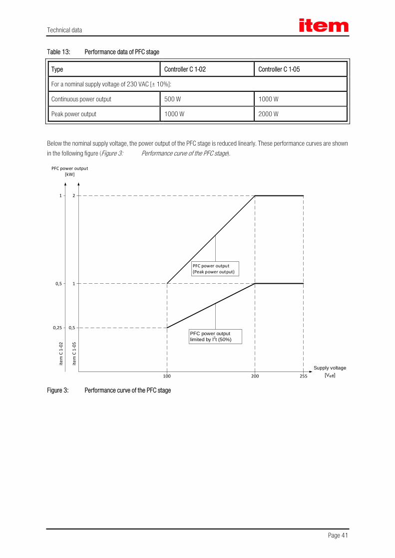
Table 13: Performance data of PFC stage..............................................................................................41
Table 14: Technical data: Motor connection [X6] ....................................................................................42
Table 15: Controller C 1-02: Rated current for an ambient temperature of ≤ 40 °C .........................................44
Table 16: Controller C 1-05: Rated current for an ambient temperature of ≤ 40 °C .........................................44
Table 17: Controller C 1-08: Rated current for blocked or slowly rotated servo motor (fel) ≤ 2 Hz and for an ambient temperature of ≤ 40 °C ........................................................................................................45
Table 18: Controller C 1-08: Rated current for rotated servo motor (fel) ≥ 3 Hz and for an ambient temperature of ≤ 40 °C ..............................................................................................................................46
Table 19: Technical data: Resolver [X2A] ..............................................................................................48
Table 20: Technical data: Resolver interface [X2A] ..................................................................................48
Table 21: Technical data: RS232 [X5] ..................................................................................................51
Table 22: Technical data: USB [X19] ....................................................................................................51
Table 23: Technical data: Ethernet [X18] ..............................................................................................51
Table 24: Technical data: CAN bus [X4] ................................................................................................51
Table 25: Technical data: SD/MMC card ...............................................................................................52
Table 26: Technical data: Digital inputs and outputs [X1] ..........................................................................52
Table 27: Technical data: Analog inputs and outputs [X1] .........................................................................53
Table 28: Technical data: Incremental encoder input [X10] .......................................................................53
Table 29: Technical data: Incremental encoder output [X11] .....................................................................54
Table 30: Output voltage at the motor terminals in the case of a DC bus circuit voltage (UZK) of 360 V .................57
Table 31: Table overview of the DIP switch functionality............................................................................66

Page 13
Table 32: Fieldbus specific assignment of the DIP switches .......................................................................68
Table 33: Pin assignment: [X9] ...........................................................................................................81
Table 34: Pin assignment: [X6] ...........................................................................................................84
Table 35: Pin assignment: I/O communication [X1]..................................................................................90
Table 36: Pin assignment: [X2A] .........................................................................................................92
Table 37: Pin assignment: CAN-Bus [X4] ...............................................................................................94
Table 38: Pin assignment: RS232 interface [X5] .....................................................................................97
Table 39: Pin assignment: USB interface [X19] .......................................................................................99
Table 40: Pin assignment: SD card ....................................................................................................101
Table 41: Pin assignment: MMC card .................................................................................................101
Table 42: EMC requirements: First and second environment ....................................................................104
Table 43: Operating mode and error display ........................................................................................113
Table 44: Error messages ................................................................................................................115
Table 45: Technical data: PROFIBUS-DP interface: Ambient conditions, dimensions and weight .......................147
Table 46: Technical data: PROFIBUS-DP interface: Interfaces and communication ........................................148
Table 47: Pin assignment: PROFIBUS-DP interface ................................................................................149
Table 48: Technical data: EhterCAT module: Ambient conditions, dimensions and weight ..............................152
Table 49: Display elements ..............................................................................................................152
Table 50: Signal level and differential voltage .......................................................................................153

General
Page 14
1 General
1.1 Documentation This product manual serves the purpose of a safe use of the item servo positioning controller C 1-Series. It contains safety notes, which must be complied with.
Further information can be found in the following manuals of the item C Series product range:
Product Manual "item Servo Positioning Controller C 3-Series": Description of the technical data and the device functionality plus notes concerning the installation and operation of C 3-05 and C 3-10 servo positioning controllers.
Product Manual “FSM 2.0 - STO”: Description of the technical data and device functionality plus notes on the installation and operation of the FSM 2.0 – STO.
PROFIBUS Manual “item Servo Positioning Controller C Series”: Description of the implemented PROFIBUS-DP protocol.
CANopen Manual “item Servo Positioning Controller C Series“: Description of the implemented CANopen protocol as per DSP402.
EtherCAT Manual “item Servo Positioning Controller C Series”: Description of the implemented EtherCAT protocol (CoE) (German version).
You can find all these documents on our homepage at the download area (http://www.item24.com).
Certificates and declarations of conformity for the products described in this manual can be found at http://www.item24.com.
The entire software functionality of the new item C Series product range will be implemented in the course of a step-by-step development process.
This version of the product manual contains the functions of the firmware version 4.1.7001.1.1.

General
Page 15
1.2 Scope of supply The scope of supply includes:
Table 1: Scope of supply
1x item Servo Positioning Controller C 1-Series
Type C 1-02 C 1-05 C 1-08
item order number 0.0.668.62 0.0.668.63 0.0.668.64
Counterplugs for power are included in standard scope of supply. Counterplugs for controller or shaft encoder connections, as well as for shield connection are not included in the standard scope of supply. They can, however, be ordered as accessories.
Table 2: Connector set: POWER connector
1x Connector set: POWER connector This plug set contains the counterplugs for the following connections: - Supply [X9] - Motor connection [X6]
Type C 1-02 C 1-05 C 1-08
item order number available on request available on request
Table 3: Connector set: DSUB connector
1x Connector set: DSUB connector This connector set includes the counterplugs for the following connections: - I/O interface [X1] - Angle encoder connection [X2A] - Angle encoder connection [X2B] - CAN fieldbus interface [X4] - Incremental encoder input [X10] - Incremental encoder output [X11]
Type C 1-02 C 1-05 C 1-08
item order number available on request
Table 4: Connector set: Shield connector
1x Connector set: Shield connector This connector set includes two shield terminals (SK14)
Type C 1-02 C 1-05 C 1-08
item order number 0.0.668.19

Safety notes for electrical drives and controllers
Page 16
2 Safety notes for electrical drives and controllers
2.1 Used symbols
Information
Important information and notes.
Caution!
Nonobservance may result in severe property damages.
DANGER!
Nonobservance may result in property damages and in personal injuries.
Caution! Dangerous voltages. The safety note indicates a possible perilous voltage.
Safety notes for electrical drives and controllers
Page 17
2.2 General notes In case of damage resulting from non-compliance with the safety notes in this manual, item Industrietechnik GmbH will not assume any liability.
Prior to the initial use you must read the Safety notes for electrical drives and controllers starting on page 16 and chapter 8.11 Notes on safe and EMC-compliant installation, starting on page 103.
If the documentation in the language at hand is not understood accurately, please contact and inform your supplier.
Sound and safe operation of the servo positioning controller requires proper and professional transportation, storage, mechanical installation, and project planning – with a consideration of the risks as well as the protective and emergency measures – plus the proper and professional electrical installation, operation, and maintenance of the devices.
Only trained and qualified personnel is authorised to handle electrical devices and systems:
TRAINED AND QUALIFIED PERSONNEL
in the sense of this product manual or the safety notes on the product itself are persons who are sufficiently familiar with the project, the setup, assembly, commissioning and operation of the product as well as all warnings and precautions as per the instructions in this manual and who are sufficiently qualified in their field of expertise:
Education and instruction concerning the standards and accident prevention regulations for the application, or authorisation to switch devices/systems on and off and to ground them as per the standards of safety engineering and to efficiently label them as per the job demands.
Education and instruction as per the standards of safety engineering regarding the maintenance and use of adequate safety equipment.
First aid training.
The following notes must be read prior to the initial operation of the system to prevent personal injuries and/or property damages:
These safety notes must be complied with at all times.
Do not try to install or commission the servo positioning controller before carefully reading all safety notes for electrical drives and controllers contained in this document. These safety instructions and all other user notes must be read prior to any work with the servo positioning controller.
In case you do not have any user notes for the servo positioning controller, please contact your sales representative. Immediately demand these documents to be sent to the person responsible for the safe operation of the servo positioning controller.
If you sell, rent and/or otherwise make this device available to others, these safety notes must also be included.
The user must not open the servo positioning controller for safety and warranty reasons.

Safety notes for electrical drives and controllers
Page 18
Professional control process design is a prerequisite for sound functioning of the servo positioning controller!
DANGER!
Inappropriate handling of the servo positioning controller and non-compliance with the warnings as well as inappropriate intervention in the safety features may result in property damage, personal injuries, electric shock or in extreme cases even death.

Safety notes for electrical drives and controllers
Page 19
2.3 Danger resulting from misuse
DANGER!
High electrical voltages and high load currents!
Danger to life or serious personal injury from electrical shock!
DANGER!
High electrical voltage caused by wrong connections!
Danger to life or serious personal injury from electrical shock!
DANGER!
Surfaces of device housing may be hot!
Risk of injury! Risk of burning!
DANGER!
Dangerous movements!
Danger to life, serious personal injury or property damage due to unintentional movements of the motors!

Safety notes for electrical drives and controllers
Page 20
2.4 Safety notes
2.4.1 General safety notes
The servo positioning controller corresponds to IP20 degree of protection as well as pollution degree 2. Make sure that the environment corresponds to this degree of protection and pollution degree.
Only use replacement parts and accessories approved by the manufacturer.
The devices must be connected to the mains supply as per EN regulations, so that they can be cut off the mains supply by means of corresponding separation devices (for example main switch, contactor, power switch).
The servo positioning controller may be protected using an AC/DC sensitive 300 mA fault current protection switch, type B (RCD = Residual Current protective Device).
Gold contacts or contacts with a high contact pressure should be used to switch the control contacts.
Preventive interference rejection measures should be taken for control panels, such as connecting contactors and relays using RC elements or diodes.
The safety rules and regulations of the country in which the device will be operated must be complied with.
The environment conditions defined in the product documentation must be kept. Safety-critical applications are not allowed, unless specifically approved by the manufacturer.
For notes on installation corresponding to EMC, please refer to chapter 8.11 Notes on safe and EMC-compliant installation (page 103). The compliance with the limits required by national regulations is the responsibility of the manufacturer of the machine or system.
The technical data and the connection and installation conditions for the servo positioning controller are to be found in this product manual and must be met.
DANGER!
The general setup and safety regulations for work on power installations (for example DIN, VDE, EN, IEC or other national and international regulations) must be complied with.
Non-compliance may result in death, personal injury or serious property damages.

Safety notes for electrical drives and controllers
Page 21
Without claiming completeness, the following regulations and others apply:
VDE 0100 Erection of power installations with nominal voltages up to 1000 V
EN 1037 Safety of maschinery - Prevention of unexpected start-up
EN 60204-1 Safety of machinery - Electrical equipment of machines Part 1: General requirements
EN 61800-3 Adjustable speed electrical power drive systems Part 3: EMC requirements and specific test methods
EN 61800-5-1 Adjustable speed electrical power drive systems Part 5-1: Safety requirements - Electrical, thermal and energy
EN 61800-5-2 Adjustable speed electrical power drive systems Part 5-2: Safety requirements - Functional
EN ISO 12100 Safety of machinery - General principles for design - Risk assessment and risk reduction
EN ISO 13849-1 Safety of machinery - Safety-related parts of control systems Part 1: General principles for design
EN ISO 13849-2 Safety of machinery - Safety-related parts of control systems Part 2: Validation
More standards to be respected by the user:
EN 574 Safety of machinery - Two-hand control devices
EN 1088 Safety of machinery - Interlocking devices associated with guards
EN ISO 13850 Safety of machinery - Emergency stop

Safety notes for electrical drives and controllers
Page 22
2.4.2 Safety notes for assembly and maintenance
The appropriate DIN, VDE, EN and IEC regulations as well as all national and local safety regulations and rules for the prevention of accidents apply for the assembly and maintenance of the system. The plant engineer or the operator is responsible for compliance with these regulations:
The servo positioning controller must only be operated, maintained and/or repaired by personnel trained and qualified for working on or with electrical devices.
Prevention of accidents, injuries and/or damages:
Additionally secure vertical axes against falling down or lowering after the motor has been switched off, for example by means of:
Mechanical locking of the vertical axle,
External braking, catching or clamping devices or
Sufficient balancing of the axle
The motor holding brake supplied by default or an external motor holding brake driven by the drive controller alone is not suitable for personal protection!
Keep the electrical equipment voltage-free using the main switch and protect it from being switched on again until the DC bus circuit is discharged, in the case of:
Maintenance and repair work
Cleaning
long machine shutdowns
Prior to carrying out maintenance work make sure that the power supply has been turned off, locked and the DC bus circuit is discharged.
The external or internal brake resistor carries dangerous DC bus voltages during operation of the servo positioning controller and up to 5 minutes thereafter. Contact may result in death or serious personal injury. Wait for this time prior to performing any work on the affected connections. Measure the voltages for your own protection. Contact with these high DC bus circuit voltages may result in death or serious personal injury.
Be careful during the assembly. During the assembly and also later during operation of the drive, make sure to prevent drill chips, metal dust or assembly parts (screws, nuts, cable sections) from falling into the device.
Also make sure that the external power supply of the controller (24 V) is switched off.
The DC bus circuit or the mains supply must always be switched off prior to switching off the 24 V controller supply.
Carry out work in the machine area only, if AC and/or DC supplies are switched off. Switched off output stages or controller enablings are no suitable means of locking. In the case of a malfunction the drive may

Safety notes for electrical drives and controllers
Page 23
accidentally be put into action.
This does not apply to drives with the special “Safe Stop” feature in accordance with EN 954-1 CAT 3 or with the “Safe Torque Off” feature in accordance with EN 61800-5-2.
This feature can be achieved with the item C 1-Series by integrating the module FSM 2.0 – STO for example.
Initial operation must be carried out with idle motors, to prevent mechanical damages for example due to the wrong direction of rotation.
Electronic devices are never fail-safe. It is the user’s responsibility, in the case an electrical device fails, to make sure the system is transferred into a secure state.
The servo positioning controller and in particular the brake resistor, externally or internally, can assume high temperatures, which may cause serious burns.
Safety notes for electrical drives and controllers
Page 24
2.4.3 Protection against contact with electrical parts
This section only concerns devices and drive components carrying voltages exceeding 50 V. Contact with parts carrying voltages of more than 50 V can be dangerous for people and may cause electrical shock. During operation of electrical devices some parts of these devices will inevitably carry dangerous voltages.
DANGER!
High electrical voltage!
Danger to life, danger due to electrical shock or serious personal injury!
The appropriate DIN, VDE, EN and IEC regulations as well as all national and local safety regulations and rules for the prevention of accidents apply for the assembly and maintenance of the system. The plant engineer or the operator is responsible for compliance with these regulations:
Before switching on the device, install the appropriate covers and protections against accidental contact. Rack-mounted devices must be protected against accidental contact by means of a housing, for example a switch cabinet. The national regulations for safety/accident prevention must be complied with!
Always connect the ground conductor of the electrical equipment and devices securely to the mains supply. Due to the integrated line filter the leakage current exceeds 3.5 mA!
Comply with the minimum copper cross-section for the ground conductor over its entire length (see for example EN 60800-5-1).
Prior to the initial operation, even for short measuring or testing purposes, always connect the ground conductor of all electrical devices as per the terminal diagram or connect it to the ground wire. Otherwise the housing may carry high voltages which can cause electrical shock.
Do not touch electrical connections of the components when switched on.
Prior to accessing electrical parts carrying voltages exceeding 50 Volts, disconnect the device from the mains or power supply. Protect it from being switched on again.
For the installation the amount of DC bus voltage must be considered, particularly regarding insulation and protective measures. Ensure proper grounding, wire dimensioning and corresponding short-circuit protection.
The device comprises a rapid discharge circuit for the DC bus as per EN 60204-1. In certain device constellations, however, mostly in the case of parallel connection of several servo positioning controllers in the DC bus or in the case of an unconnected brake resistor, this rapid discharge may be rendered ineffective. The servo positioning controllers can carry voltage until up to 5 minutes after being switched off (residual capacitor charge).
2.4.4 Protection against electrical shock by means of protective extra-low voltage (PELV)
All connections and terminals with voltages of up to 50 Volts at the servo positioning controller are protective extra-low voltage, which are designed safe from contact in correspondence with the following standards:
International: IEC 60364-4-41
European countries within the EU: EN 61800-5-1

Safety notes for electrical drives and controllers
Page 25
DANGER!
High electrical voltages due to wrong connections!
Danger to life, risk of injury due to electrical shock!
Only devices and electrical components and wires with a protective extra low voltage (PELV) may be connected to connectors and terminals with voltages between 0 to 50 Volts.
Only connect voltages and circuits with protection against dangerous voltages. Such protection may be achieved by means of isolation transformers, safe optocouplers or battery operation.
2.4.5 Protection against dangerous movements
Dangerous movements can be caused by faulty control of connected motors, for different reasons:
Improper or faulty wiring or cabling
Error in handling of components
Error in sensor or transducer
Defective or non-EMC-compliant components
Software error in superordinated control system
These errors can occur directly after switching on the device or after an indeterminate time of operation.
The monitors in the drive components for the most part rule out malfunctions in the connected drives. In view of personal protection, particularly the danger of personal injury and/or property damage, this may not be relied on exclusively. Until the built-in monitors come into effect, faulty drive movements must be taken into account; their magnitude depends on the type of control and on the operating state.
DANGER!
Dangerous movements!
Danger to life, risk of injury, serious personal injuries or property damage!
For the reasons mentioned above, personal protection must be ensured by means of monitoring or superordinated measures on the device. These are installed in accordance with the specific data of the system and a danger and error analysis by the manufacturer. The safety regulations applying to the system are also taken into consideration. Random movements or other malfunctions may be caused by switching the safety installations off, by bypassing them or by not activating them.

Safety notes for electrical drives and controllers
Page 26
2.4.6 Protection against contact with hot parts
DANGER!
Housing surfaces may be hot!
Risk of injury! Risk of burning!
Do not touch housing surfaces in the vicinity of heat sources! Danger of burning!
Before accessing devices let them cool down for 10 minutes after switching them off.
Touching hot parts of the equipment such as the housing, which contain heat sinks and resistors, may cause burns!

Safety notes for electrical drives and controllers
Page 27
2.4.7 Protection during handling and assembly
Handling and assembly of certain parts and components in an unsuitable manner may under adverse conditions cause injuries.
DANGER!
Risk of injury due to improper handling!
Personal injury due to pinching, shearing, cutting, crushing!
The following general safety notes apply:
Comply with the general setup and safety regulations on handling and assembly.
Use suitable assembly and transportation devices.
Prevent incarcerations and contusions by means of suitable protective measures.
Use suitable tools only. If specified, use special tools.
Use lifting devices and tools appropriately.
If necessary, use suitable protective equipment (for example goggles, protective footwear, protective gloves).
Do not stand underneath hanging loads.
Remove leaking liquids on the floor immediately to prevent slipping.
Product description
Page 28
3 Product description
3.1 General The item servo positioning controller C Series devices are intelligent AC servo inverters with substantial parameterisation possibilities and extension options. They are flexible and can be easily adapted to a number of different applications.
These servo positioning controllers are designed for receiving so-called FSM modules (Functional Safety Modules). Thanks to their integrated safety features, external monitoring devices can be omitted for numerous applications.
The series includes types with single-phase and three-phase supply.
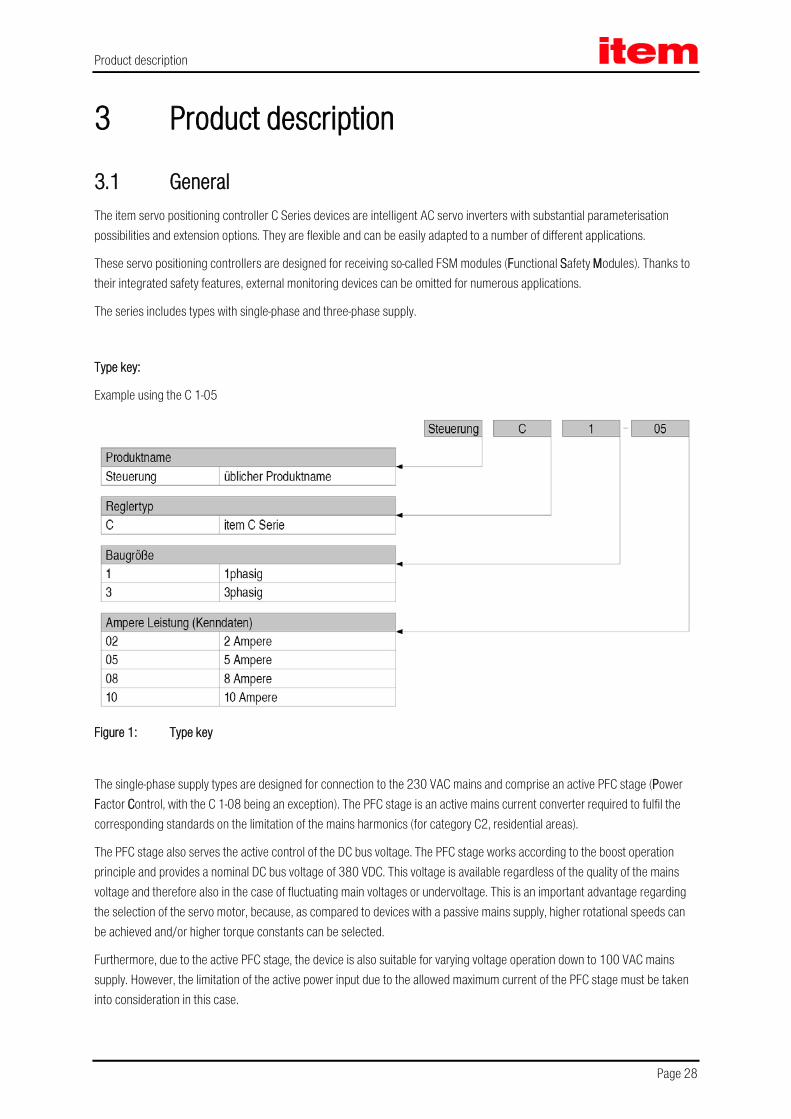
Type key:
Example using the C 1-05
Figure 1: Type key
The single-phase supply types are designed for connection to the 230 VAC mains and comprise an active PFC stage (Power Factor Control, with the C 1-08 being an exception). The PFC stage is an active mains current converter required to fulfil the corresponding standards on the limitation of the mains harmonics (for category C2, residential areas).
The PFC stage also serves the active control of the DC bus voltage. The PFC stage works according to the boost operation principle and provides a nominal DC bus voltage of 380 VDC. This voltage is available regardless of the quality of the mains voltage and therefore also in the case of fluctuating main voltages or undervoltage. This is an important advantage regarding the selection of the servo motor, because, as compared to devices with a passive mains supply, higher rotational speeds can be achieved and/or higher torque constants can be selected.
Furthermore, due to the active PFC stage, the device is also suitable for varying voltage operation down to 100 VAC mains supply. However, the limitation of the active power input due to the allowed maximum current of the PFC stage must be taken into consideration in this case.

Product description
Page 29
All item Servo Positioning Controller C Series devices have the following features:
Space-saving compact design, directly cascadable
High quality of control due to extremely high-quality sensor technology, far superior to conventional market standards, and better than average computer resources
Complete integration of all of the components for the controller and power module, including USB, Ethernet, and RS232 for the PC communication, plus CANopen for the integration into automation systems
SD card: support of FW downloads (initialisation via boot switches) and uploads and downloads of parameter sets
Integrated universal encoder evaluation for the following encoders:
Resolver
Incremental encoder with/without commutation signals
High-resolution Stegmann incremental encoders, absolute encoders with HIPERFACE®
High-resolution Heidenhain incremental encoders, absolute encoders with EnDat
Compliance with current European regulations and associated standards without any additional external measures
Device design as per UL standards, cULus certified
Completely closed, EMC-optimized metal housing for mounting to conventional control cabinet plates. All devices comply with the IP20 degree of protection
Integration of all filters to fulfil the EMC regulations (industrial) inside the device, for example line filter, motor output filter, filter for 24 V-supply as well as inputs and outputs
Integrated brake resistor. External resistors can be connected for higher braking energies
Automatic identification of externally connected brake resistors
Complete galvanic separation of controller and power output stage as per EN 61800-5-1. Galvanic separation of the 24 V potential area with the digital inputs and outputs, analog electronics and the controller electronics
Operation as speed controller, torque controller or positioning controller
Integrated positioning control with wide range of functions as per CAN in Automation (CiA) DSP402 and numerous additional application-specific functions
Jerk limit or time-optimal positioning relative or absolute to a point of reference
Point-to-point positioning (with or without S-ramps)
Speed and angle synchronisation with electronic gear system via incremental encoder input or fieldbus
Extensive modes of operation for synchronisation
Various methods for homing
Jogging
Teach-in mode
Short cycle times, in current control circuit 50 µs (20 kHz), in speed control circuit 100 µs (10 kHz)
Switchable clock frequency for the power output stage
Freely programmable I/O‘s

Product description
Page 30
User-friendly parameterisation with the item Motion Soft® software
Menu-driven first set up
Automatic motor identification
Easy coupling to host controller, for example to a PLC via I/O level or fieldbus
High-resolution 16-bit analog input
Technology slots for extensions such as I/O extension module or PROFIBUS interface. Note: Depending on the current consumption, only one technology module with an additional fieldbus interface may be used
Option “STO” (Safe Torque Off, corresponds to EN 60204 Stop 0), SIL 3 in accordance with ISO EN 61800-5-2 / PL e in accordance with ISO EN 13849-1

Product description
Page 31
3.2 Power supply
3.2.1 Single-phase AC supply with active PFC
The item servo positioning controller C 1-Series fulfils the following demands on a servo positioning controller with active PFC stage (with the C 1-08 being an exception):
Fulfilment of current standards regarding mains harmonics (EN 61000-3-2)
cosϕ° > 0.97 at nominal operation (at rated output power of the PFC stage)
Sinusoidal mains current, harmonic distortion < 4 % (at rated output power of the PFC stage)
Controlled average value of DC bus voltage of 380 VDC
Insensitive in the case of weak mains and short mains interruptions. In such cases the device maintains stable (within the physical possibilities) without malfunctions
Wide input voltage range, rated voltage 230 VAC
Frequency range nominal 50-60 Hz ±10 %
Electrical impulse load capacity for possible combination of several servo positioning controllers. The item servo positioning controller C 1-Series allows dynamic conversion in both directions between motor and generator operation without dead times
No parameterisation by user necessary
3.2.1.1 Behaviour during switch-on
As soon as the item servo positioning controller C 1-Series is supplied with the input voltage, the DC bus is charged (< 1 s) using the brake resistor as a precharging resistor, the DC link relay deactivated. During this the PFC remains inactive
After precharging of the DC bus the relay is energized and the DC bus is coupled hard to the mains power without the precharging resistor. Subsequently, the PFC stage is activated and the DC bus is boosted to the full DC bus voltage
If the DC bus voltage after precharging is too small, because the input mains voltage is below the PFC operation input voltage range, the PFC stage remains inactive and an error message on the seven segment display is shown
If the item servo positioning controller C 1-Series is supplied with less than the nominal voltage of 230 VAC, the actual DC bus voltage after the precharge is used to compute a power derating for the PFC stage (see chapter 4.3 Supply [X9], page 40 and Figure 3)

Product description
Page 32
3.2.1.2 Behaviour during normal operation and control characteristics
During operation the PFC stage controls the power input of the item servo positioning controller C 1-Series from the supply. Based on an analog closed-loop control the mains current is regulated to a sinusoidal waveform with a phase shift near to 0 °. The effective amplitude is adjusted according to the demanded input power
A superimposed digital closed-loop control adjusts the DC bus voltage to an average value close to 380 VDC. To relieve the voltage control that is relatively sluggish, during load changes (acceleration/deceleration of the drive) the output/input power delivered from the item servo positioning controller C 1-Series to the motor is measured and used for the pre-control of the PFC stage
+
-
~ ~3 phasepowerstage
M3 ~
microcontroller
voltagecontroller motion controller
IC for power factorcorrection
L D
C
u_q
i_q
PWM
U_Zk i_vi_u
T8
I_inU_in
100V ... 230V AC+/- 10%
F
motorfeedback
Figure 2: Schematic setup of PFC stage
The control system includes the following values:
digital control of the DC bus voltage to an average value of 380 VDC
analog control of the input mains current
Keeping of a sinusoidal mains current under stationary load conditions
cosϕ > 0.97 at nominal operation (at rated output power of the PFC stage)
By use of the parameterisation program item Motion Soft® the PFC stage (Parameters/Device parameters/PFC) can be switched on and off. With deactivated PFC the DC bus behaves like a normal DC bus with a rectifier bridge
Under stationary load conditions the DC bus voltage is regulated to a constant average value, which is independent from the actual power transferred to the motor.

Product description
Page 33
3.2.2 DC bus coupling, DC supply
3.2.2.1 DC bus coupling
It is possible to couple multiple servo positioning controllers of the item C 1-Series when they have the same DC bus voltage. For this purpose, the PFC stage has to be deactivated
Caution!
DC bus coupling is not allowed while the PFC stage is active. This can otherwise result in damages to the servo positioning controller.
Caution!
When the DC buses are connected, the power supplies must be connected to the same mains phase.
This means, if two C 1-05 are coupled in the DC bus, only the connection L1/N is possible for both devices. It is not allowed to connect the DC Busses if the devices are connected to different mains phases.
It is forbidden to supply device 1 via L1/N and device 2 via L2/N, when the DC buses are coupled.
Caution!
Operation with DC bus coupling together with devices of the item C 3-Series is not allowed.
3.2.2.2 DC supply
The direct DC supply is supported for a supply with voltages ≥ 60 VDC by the DC-bus connection instead of the connection to the mains
The digital motor temperature measurement system requires a DC-link voltage of 120 VDC minimum. Below this voltage, the system will always identify the digital motor temperature sensor as open.
3.2.3 Mains fuse
A slow-blow (B16) single-phase automatic circuit breaker of 16 A has to be installed in the mains supply line.

Product description
Page 34
3.3 Brake chopper A brake chopper with a brake resistor is integrated into the power output stage. If during the generator operation the permissible charging capacity of the DC bus is exceeded, the braking energy can be converted into heat by the internal brake resistor. The brake chopper is software-driven. The internal brake resistor is overload-protected by means of software and hardware.
If in a special application the power of the internal resistors should be insufficient, they can be cut off by removing the bridge between the pin BR-CH and BR-INT of the [X9] plug. Instead, an external brake resistor is inserted between the pins BR-CH and ZK+. This brake resistor must fulfil certain minimum specifications (see Table 12, page 40). The output is protected against short-circuiting in the brake resistor or its cable.
Pin BR-CH lies on positive DC bus potential and is thus not protected against ground fault or short-circuits against mains voltage or negative DC bus voltages.
Simultaneous use of the internal and external brake resistors is not possible. The external resistors are not automatically overload-protected by the device.
3.4 Communication interfaces The item servo positioning controller C Series has several communication interfaces. The basic device itself is already equipped with many of these interfaces.
The following communication interfaces are included in the basic device:
Serial interface [X5]: RS232/RS485
USB interface [X19]: USB
UDP interface [X18]: Ethernet
Fieldbus system [X4]: CANopen
I/O interface [X1]: Digital and analog In- and outputs
The serial, Ethernet, and USB interface are particularly important for the connection of a PC and for the use of the item Motion Soft® parameterisation tool.
The fieldbus systems PROFIBUS-DP and EtherCAT are extension options that can be implemented in the form of plug-in modules. If required, customer-specific fieldbus protocols can also be realised.
In any case, the servo positioning controller of this design always works as a slave to the fieldbus.

Product description
Page 35
3.4.1 Serial interface [X5]
The RS232 protocol is mainly intended to be a parameterisation interface, but also allows the control of the item servo positioning controller C Series.
3.4.2 USB interface [X19]
This interface, too, was mainly intended as a parameterisation interface, but it can also be used for controlling the item servo positioning controller C Series.
3.4.3 UDP interface [X18]
The UDP communication enables the connection of the item servo positioning controller C Series to the Ethernet fieldbus system. The communication via the UDP interface [X18] is realised with the aid of a standard cabling.
3.4.4 CAN interface [X4]
The CANopen protocol as per DS301 with application profile DSP402 is implemented.

Product description
Page 36
3.4.5 Technology module: PROFIBUS
Support of PROFIBUS communication as per DP-V0. For drive technology applications the functions as per PROFIDRIVE Version 3.0 are available. The features include functions as per Application Class 1 (speed and torque control) as well as per Application Class 3 (point-to-point positioning).
It is also possible to include the device into control systems via an I/O mapping via PROFIBUS. From a control point of view, this option offers the same functionality as a conventional PLC coupling via parallel wiring with the device’s digital I/Os.
Via a special item telegram it is also possible to access all device-specific functions, exceeding the functionality defined by PROFIDRIVE.
3.4.6 Technology module: EtherCAT
The EtherCAT interface enables the connection of the item servo positioning controller C Series to the EtherCAT fieldbus system. The communication via the EtherCAT interface (IEEE-802.3u) is realised with the aid of EtherCAT standard cabling.
3.4.7 I/O functions and device control
Ten digital inputs provide the elementary control functions (see chapter 4.6.6 I/O interface [X1], page 52):
The item C Series comprises a target table, in which the positioning targets are stored and from which they can later be retrieved. At least four digital inputs serve the purpose of target selection; one input is used as a start input.
The limit switches serve the safety limitation of the motion space. During a homing one of the two limit switches may serve as a reference point for the positioning control.
Two inputs are used for the power stage enabling on the hardware side as well as for the controller enabling on the software side.
High-speed sample inputs are available for different time-critical applications (for example homing, special applications).
The item servo positioning controller C Series has three analog inputs for input levels in the range of +10V to -10V. One input is designed as a differential input (16 bit), to guarantee high interference immunity. Two inputs (10 bit) are single-ended. The analog signals are quantized and digitalized by an analog-digital converter at a resolution of 16 bit or 10 bit. The analog signals provide the setpoints (speed or torque) for the control.
In common applications the existing digital inputs are already used for basic functions. For the use of further functions such as teach-in mode, separate “start homing” input or stop input, the analog inputs AIN 1, AIN 2 as well as the digital outputs DOUT 2 and DOUT 3, which are also usable as digital inputs, can optionally also be used.

Technical data
Page 37
4 Technical data
4.1 General Technical data Table 5: Technical data: Ambient conditions and qualification
Range Values
Admissible temperature ranges Storage temperature: -25 °C to +70 °C
Operating temperature: 0 °C to +40 °C
+40 °C to +50 °C at reduced power 2,5 %/K
Admissible installation height Mounting height maximum 2000 m above msl, above 1000 m above msl with power reduction 1% per 100 m
Humidity Relative humidity up to 90 %, not bedewing
Protection degree IP20
Protection class I
Pollution degree 2
CE conformity Low-voltage directive:
EMC directive:
2006/95/EC verified by application of the harmonised standard EN 61800-5-1
2004/108/EC verified by application of the harmonised standard EN 61800–3
cULus certification Listed according to UL 508C, C22.2 No. 274-13
Table 6: Technical data: Dimensions and weight
Type Controller C 1-02 Controller C 1-05 Controller C 1-08
Dimensions including the mounting plate (H*W*D)
261 mm*54,6 mm*205 mm
Dimensions (H*W*D) 200 mm*54 mm*200 mm
Weight approx. 2,0 kg approx. 2,1 kg approx. 1,8 kg

Technical data
Page 38
Table 7: Technical data: Cable specifications
Range Controller C 1-02
Controller C 1-05
Controller C 1-08
Maximum motor cable length for interference emission as per EN 61800-3 for fPWM 10 kHz
Category C2
Switch cabinet assembly (see chapter 8.11 Notes on safe and EMC-compliant installation)
l ≤ 25 m
Category C3
(industrial area)
l ≤ 25 m
Cable capacity of a phase against shield or between two lines C‘ ≤ 200 pF/m
Derating of the cable length (see also chapter 8.11.5 Operation with long motor cables)
fPWM = 12 kHz l ≤ 21 m
fPWM = 16 kHz l ≤ 15 m
fPWM = 20 kHz l ≤ 12 m
Table 8: Technical data: Motor temperature monitoring
Motor temperature monitoring Values
Digital Sensor Normally closed contact: Rcold < 500 Ω Rhot > 100 kΩ
Analog Sensor Silicon temperature sensor, for example KTY81, 82 or similar R25 ≈ 2000 Ω R100 ≈ 3400 Ω

Technical data
Page 39
4.2 Operating and display elements On the front the item Servo Positioning Controller C 1-Series has two LEDs and one seven-segment display to indicate the operating status.
Table 9: Display elements and RESET button
Element Function
Seven segment display Display of operating mode and a coded error number in the case of a malfunction
LED 1 (two-color LED, green/red)
Operational state respectively fault
LED 2 (green) Controller enable
LED 3 (yellow) Status display CAN bus
RESET-Button Hardware reset for processor
Technical data
Page 40
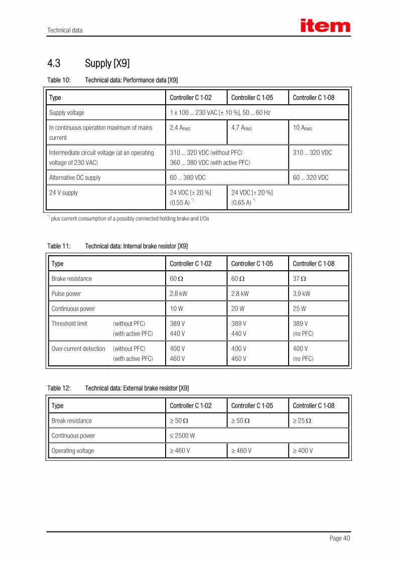
4.3 Supply [X9] Table 10: Technical data: Performance data [X9]
Type Controller C 1-02 Controller C 1-05 Controller C 1-08
Supply voltage 1 x 100 ... 230 VAC [± 10 %], 50 ... 60 Hz
In continuous operation maximum of mains current
2,4 ARMS 4,7 ARMS 10 ARMS
Intermediate circuit voltage (at an operating voltage of 230 VAC)
310 ... 320 VDC (without PFC) 360 ... 380 VDC (with active PFC)
310 ... 320 VDC
Alternative DC supply 60 ... 380 VDC 60 ... 320 VDC
24 V supply 24 VDC [± 20 %] (0,55 A) *)
24 VDC [± 20 %] (0,65 A) *)
*) plus current consumption of a possibly connected holding brake and I/Os
Table 11: Technical data: Internal brake resistor [X9]
Type Controller C 1-02 Controller C 1-05 Controller C 1-08
Brake resistance 60 Ω 60 Ω 37 Ω
Pulse power 2,8 kW 2,8 kW 3,9 kW
Continuous power 10 W 20 W 25 W
Threshold limit (without PFC) (with active PFC)
389 V 440 V
389 V 440 V
389 V (no PFC)
Over-current detection (without PFC) (with active PFC)
400 V 460 V
400 V 460 V
400 V (no PFC)
Table 12: Technical data: External brake resistor [X9]
Type Controller C 1-02 Controller C 1-05 Controller C 1-08
Break resistance ≥ 50 Ω ≥ 50 Ω ≥ 25 Ω
Continuous power ≤ 2500 W
Operating voltage ≥ 460 V ≥ 460 V ≥ 400 V
Technical data
Page 41
Table 13: Performance data of PFC stage
Type Controller C 1-02 Controller C 1-05
For a nominal supply voltage of 230 VAC [± 10%]:
Continuous power output 500 W 1000 W
Peak power output 1000 W 2000 W
Below the nominal supply voltage, the power output of the PFC stage is reduced linearly. These performance curves are shown in the following figure (Figure 3: Performance curve of the PFC stage).
100 255200
2
Supply voltage [Veff]
PFC power output [kW]
item
C 1
-05
item
C 1
-02
1
10,5
0,25 0,5PFC power output limited by l2t (50%)
PFC power output (Peak power output)
Figure 3: Performance curve of the PFC stage

Technical data
Page 42
4.4 Motor connection [X6] Table 14: Technical data: Motor connection [X6]
Type Controller C 1-02 Controller C 1-05 Controller C 1-08
Specifications for operation with 1x 230 VAC [± 10 %], 50 Hz
Output power 0,5 kVA 1,0 kVA 1,5 kVA
Max. output power for 5s 1,0 kVA 2,0 kVA 3,0 kVA
Output current 2,5 ARMS 5 ARMS 8 ARMS
Max. output current for 5s 5 ARMS 10 ARMS 16 ARMS
Max. output current 0,5s
10 ARMS
20 ARMS
32 ARMS
(fel ≥ 3 Hz) *)
Current derating from 12 kHz 12 kHz 10 kHz
Max. clock frequency approx. 20 kHz
Holding brake 24 V Signal level dependent on switch status, high side / low side switch / max. 2 A
Motor temperature sensor N.C. and N.O. contact, PTC, KTY … + 3,3 V / 5 mA
Power loss/efficiency (with regard to the rated output power)**)
typical 8% / 92%
*) with smaller electrical rotational frequencies (fel) shorter permissible times are valid with C 1-08; see the following tables **) "As a guideline".
4.4.1 Current derating
Differently from the indicated technical motor data the item Servo Positioning Controller C 1-Series have a current derating during nominal operation. The rated current and the time of the maximum allowed peak current of the servo positioning controller depend on different factors.
These factors are:
Output current level (the higher the output current, the shorter the allowed time)
Power stage clock frequency (the higher the clock frequency, the shorter the allowed time)
Electrical rotational frequency of the motor (speed multiplied by pole pair number; the higher the rotational frequency, the longer the allowed time)

Technical data
Page 43
The last point (electrical rotational frequency) only applies to the C 1-08. For a better clarity, we only distinguish between electrical rotational frequencies less than 2 Hz and those over 3 Hz. For rotational frequencies lying in between these two values, interpolation is required.
Therefore, in the following you will find two tables for the C 1-08: the first one applies to blocked or slowly rotated motors (electrical rotational frequency ≤ 2 Hz); the second one applies to faster rotated motors (electrical rotational frequency ≥ 3 Hz).
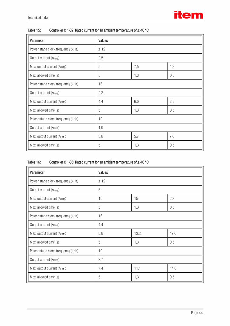
Technical data
Page 44
Table 15: Controller C 1-02: Rated current for an ambient temperature of ≤ 40 °C
Parameter Values
Power stage clock frequency (kHz) ≤ 12
Output current (ARMS) 2,5
Max. output current (ARMS) 5 7,5 10
Max. allowed time (s) 5 1,3 0,5
Power stage clock frequency (kHz) 16
Output current (ARMS) 2,2
Max. output current (ARMS) 4,4 6,6 8,8
Max. allowed time (s) 5 1,3 0,5
Power stage clock frequency (kHz) 19
Output current (ARMS) 1,9
Max. output current (ARMS) 3,8 5,7 7,6
Max. allowed time (s) 5 1,3 0,5
Table 16: Controller C 1-05: Rated current for an ambient temperature of ≤ 40 °C
Parameter Values
Power stage clock frequency (kHz) ≤ 12
Output current (ARMS) 5
Max. output current (ARMS) 10 15 20
Max. allowed time (s) 5 1,3 0,5
Power stage clock frequency (kHz) 16
Output current (ARMS) 4,4
Max. output current (ARMS) 8,8 13,2 17,6
Max. allowed time (s) 5 1,3 0,5
Power stage clock frequency (kHz) 19
Output current (ARMS) 3,7
Max. output current (ARMS) 7,4 11,1 14,8
Max. allowed time (s) 5 1,3 0,5

Technical data
Page 45
Table 17: Controller C 1-08: Rated current for blocked or slowly rotated servo motor (fel) ≤ 2 Hz and for an ambient temperature of ≤ 40 °C
Parameter Values
Power stage clock frequency (kHz) ≤ 10
Output current (ARMS) 8
Max. output current (ARMS) 16 24 32
Max. allowed time (s) 5 0,7 0,2
Power stage clock frequency (kHz) 12
Output current (ARMS) 7,4
Max. output current (ARMS) 14,8 22,2 29,6
Max. allowed time (s) 5 0,7 0,2
Power stage clock frequency (kHz) 16
Output current (ARMS) 6,3
Max. output current (ARMS) 12,6 18,9 25,2
Max. allowed time (s) 5 0,7 0,2
Power stage clock frequency (kHz) 19
Output current (ARMS) 5,2
Max. output current (ARMS) 10,4 15,6 20,8
Max. allowed time (s) 5 0,7 0,2

Technical data
Page 46
Table 18: Controller C 1-08: Rated current for rotated servo motor (fel) ≥ 3 Hz and for an ambient temperature of ≤ 40 °C
Parameter Values
Power stage clock frequency (kHz) ≤ 10
Output current (ARMS) 8
Max. output current (ARMS) 16 24 32
Max. allowed time (s) 5 1,3 0,5
Power stage clock frequency (kHz) 12
Output current (ARMS) 7,4
Max. output current (ARMS) 14,8 22,2 29,6
Max. allowed time (s) 5 1,3 0,5
Power stage clock frequency (kHz) 16
Output current (ARMS) 6,3
Max. output current (ARMS) 12,6 18,9 25,2
Max. allowed time (s) 5 1,3 0,5
Power stage clock frequency (kHz) 19
Output current (ARMS) 5,2
Max. output current (ARMS) 10,4 15,6 20,8
Max. allowed time (s) 5 1,3 0,5

Technical data
Page 47
4.5 Motor feedback connection [X2A] Different feedback systems can be connected to the item Servo Positioning Controller C 1-Series via the universal encoder interface:
Resolver (interface [X2A]) Encoder (interface [X2B])
Incremental encoders with analogue and digital track signals SinCos encoder (single-turn/multi-turn) with HIPERFACE® Multiturn absolute encoder with EnDat
The encoder type is determined in the item Motion Soft® parameterisation software.
The feedback signal is available via the incremental encoder output [X11] for master-slave applications.
It is possible to evaluate two shaft encoder systems in parallel. Typically, the resolver for the current control is connected to [X2A], and for example an absolute encoder is connected to [X2B] as a feedback system for the positioning control.

Technical data
Page 48
4.5.1 Resolver connection [X2A]
The 9-pin D-SUB connection [X2A] is used to evaluate standard resolvers. Single- and multi-pole resolvers are supported. The user can state the number of pairs of poles of the servo motor in the "Motor Data" menu of the item Motion Soft® parameterization program so that the item C 1-Series determines the speed correctly. However, the number of pairs of poles can also be identified automatically. The number of pairs of poles of the motor (P0Motor) is always an integer multiple of the number of pairs of poles of the resolver (P0Resolver). Wrong combinations such as, for example, P0Resolver = 2 and P0Motor = 5 lead to an error message during motor identification.
The resolver offset angle, which is determined automatically during the identification, is readable and writeable for service purposes.
Table 19: Technical data: Resolver [X2A]
Parameter Values
Transformation ratio 0,5
Carrier frequency 5 to 10 kHz
Excitation voltage 7 VRMS, short circuit-proof
Impedance excitation (at 10kHz) ≥ (20 + j20) Ω
Impedance stator ≤ (500 + j1000) Ω
Table 20: Technical data: Resolver interface [X2A]
Parameter Values
Resolution 16 Bit
Delay time signal detection < 200 µs
Speed resolution approximately 4 min-1
Absolute accuracy of angle detection < 5´
Max. rotational speed 16.000 min-1
4.5.2 Encoder connection [X2B]
At the 15-pole D-Sub connection [X2B], motors with encoder can be fed back. The possible incremental encoders for the encoder connection are divided into several groups. If you want to use other types of encoders, please contact your sales representative.

Technical data
Page 49
Standard incremental encoders without commutation signals: This type of encoder is used with low-cost linear motor applications, to save the costs for the provision of the commutation signals (hall sensor). With this type of encoder the ARS 2100 SE series servo drives carry out an automatic pole position determination after power-on.
Standard incremental encoders with commutation signals: These are standard incremental encoders with three binary hall sensor signals. The number of lines of the encoder can be freely parameterised (1 – 16384 lines/rotation). There is an additional offset angle for the hall sensor signals. It is determined during motor identification or can be set via the parameterisation software Metronix ServoCommander®. In general, the hall sensor offset angle is zero.
Sick-Stegmann encoders: Single-turn and multi-turn shaft encoders with HIPERFACE® made by Sick-Stegmann are supported. The following series of encoders can be connected:
Singleturn SinCos encoders: SCS 60/70, SKS 36, SRS 50/60/64, SEK 34/37/52 Multiturn SinCos encoders: SCM 60/70, SKM 36, SRM 50/60/64, SEL 34/37/52 Singleturn SinCos Hollow shaft encoders: SCS-Kit 101, SHS 170, SCK 25/35/40/45/50/53 Multiturn SinCos Hollow shaft encoders: SCM-Kit 101, SCL 25/35/40/45/50/53
In addition, the following Sick Stegmann encoder systems can be connected and evaluated:
Absolute, non-contact length measuring system L230 and TTK70 (HIPERFACE®) Digital incremental encoder CDD 50

Technical data
Page 50
ISinCoder® encoders like SNS 50 or SNS 60 are no longer supported.
Heidenhain encoders: Incremental and absolute encoders by Heidenhain are evaluated. The following series of encoders can be connected:
Analog incremental encoders: ROD 400, ERO 1200/1300/1400, ERN 100/400/1100/1300 Singleturn absolute encoders (EnDat 2.1/2.2): ROC 400, ECI 1100/1300, ECN 100/400/1100/1300 Multiturn absolute encoders (EnDat 2.1/2.2): ROQ 400, EQI 1100/1300, EQN 100/400/1100/1300 Absolute length measuring system (EnDat 2.1/2.2): LC 100/400
Yaskawa encoders:
Digital incremental encoders with zero-pulse [Σ (sigma 1), Yaskawa-OEM-protocol] made by Yaskawa are supported.

Technical data
Page 51
4.6 Communication interfaces
4.6.1 RS232 [X5]
Table 21: Technical data: RS232 [X5]
Communication interface Values
RS232 As per RS232 specification, 9600 Baud to 115.2 kBaud
4.6.2 USB [X19]
Table 22: Technical data: USB [X19]
Communication interface Values
Function USB 2.0, Slave–Client, 12 MBaud to 480 MBaud
Connector type USB-B, no current consumption from the bus (integrated power supply)
Communication protocol item specific (generic device)
4.6.3 Ethernet [X18]
Table 23: Technical data: Ethernet [X18]
Communication interface Values
Function Ethernet, 10/100 MBaud (auto select)
Connector type RJ45
4.6.4 CAN bus [X4]
Table 24: Technical data: CAN bus [X4]
Communication interface Values
CANopen controller ISO/DIS 11898, full CAN controller, max. 1 Mbaud
CANopen protocol as per DS301 and DS402

Technical data
Page 52
4.6.5 SD/MMC card
Table 25: Technical data: SD/MMC card
Communication interface Values
Card type SD, SDHC and MMC
File system FAT12, FAT16 and FAT32
4.6.6 I/O interface [X1]
Table 26: Technical data: Digital inputs and outputs [X1]
Digital inputs/outputs Values
Signal level 24 V (8 V ... 30 V) active high, conforming with DIN EN 61131-2
Logic inputs general DIN 0 DIN 1 DIN 2 DIN 3
Bit 0 \ (lsb least significant bit) Bit 1, \ Target selection for positioning Bit 2, / 16 targets selectable from target table Bit 3 / (msb most significant bit)
DIN 4 Control input power stage (enable at High)
DIN 5 Controller enable at high signal, acknowledge error with falling edge
DIN 6 Limit switch input 0
DIN 7 Limit switch input 1
DIN 8 Control signal Start positioning or
Homing switch for homing or saving of positions
DIN 9 Control signal Start positioning or
Homing switch for homing or saving of positions
Logic outputs general Galvanically separated, 24 V (8 V ... 30 V) active high
DOUT 0 Operational state 24 V, max. 100 mA
DOUT 1 Freely configurable 24 V, max. 100 mA
DOUT 2 Freely configurable, optional use as input DIN 10 24 V, max. 100 mA
DOUT 3 Freely configurable, optional use as input DIN 11 24 V, max. 100 mA
DOUT 4 [X6] Holding brake 24 V, max. 1 A

Technical data
Page 53
Table 27: Technical data: Analog inputs and outputs [X1]
Analog inputs/outputs Values
High-resolution analog input, AIN 0
± 10 V input range, 16 Bit, differentially, < 250 µs delay time
Analog input, AIN 1 Optionally, this input can also be parameterized as digital input DIN AIN 1 with a switching threshold at 8 V
± 10 V, 10 Bit, single ended, < 250 µs delay time
Analog input, AIN 2 Optionally, this input can also be parameterized as digital input DIN AIN 2 with a switching threshold at 8 V
± 10 V, 10 Bit, single ended, < 250 µs delay time
Analog outputs, AOUT 0 and AOUT 1 ± 10 V output range, 10 mA, 9 bit resolution, fLimit > 1 kHz
4.6.7 Incremental encoder input [X10]
The input supports all common incremental encoders.
For example encoders corresponding to the industry standard ROD426 by Heidenhain or encoders with single-ended TTL outputs as well as open collector outputs.
Alternatively, the A and B encoder signals are interpreted by the device as pulse-direction signals, so that the controller can also be driven by stepping motor control boards.
Table 28: Technical data: Incremental encoder input [X10]
Parameter Values
Parameterisable line count 1 – 228 lines/revolution
Trace signals: A, #A, B, #B, N, #N In accordance with RS422 specification
Max. input frequency 1000 kHz
Pulse direction interface: CLK, #CLK, DIR, #DIR, RESET, #RESET In accordance with RS422 specification
Supply output 5 V, 100 mA max.

Technical data
Page 54
4.6.8 Incremental encoder output [X11]
The output provides incremental encoder signals for processing in superimposed controls.
The signals are generated from the encoder’s angle of rotation with a freely programmable number of lines.
Besides the encoder signals A and B, the emulation also provides a reset pulse, which goes to high once per rotation (for the programmed number of lines), for the duration of a ¼ signal period (as long as the encoder signals A and B are high).
Table 29: Technical data: Incremental encoder output [X11]
Parameter Values
Number of lines Programmable 1 – 213 and 214 lines/revolution.
Connection level Differential / RS422 specification
Encoder signals A, B, N As per RS422 specification
speciality N-Trace disconnectable
Output impedance Ra,diff = 66 Ω
Limit frequency fLimit > 1,8 MHz (lines/s)
Edge sequence Can be limited by parameters
Output supply 5 V, max. 100 mA
Function overview
Page 55
5 Function overview
5.1 Motors
5.1.1 Synchronous servo motors
Typically, permanently excited synchronous motors with sinusoidal EMF are used. The item servo positioning controller C 1-Series is a universal servo positioning controller, which can be operated with standard servo motors. The motor specifications are determined and parameterized by means of an automatic motor identification.
5.1.2 Linear motors
Besides rotary applications, the item servo positioning controller C 1-Series are also suitable for linear drives. Here also, permanently excited synchronous linear motors are supported. Due to the high signal processing quality, the item C Series is particularly suitable for driving air-core and iron-core synchronous motors with low motor inductances (2 … 4 mH).

Function overview
Page 56
5.2 Functions of the item servo positioning controller C 1-Series
5.2.1 Compatibility
For compatibility reasons, from the user’s point of view, the control structure of the item C 1-Series has mostly the same characteristics, interfaces and parameters as the previous item C Series.
PWM M
Positioningcontroller
Speedcontroller
Currentcontroller
Powerstage Motor
Angle encoder1 and 2
Actual value managementX2AX2BX10
Set point management:- Analogue inputs- Fixed values- Synchronization- Ramp generator
Positioning control andInterpolationTrajectories calculation:- Reference position- Motorspeed precontrol- Motorcurrent precontrol E1 E2
Figure 4: Control scheme of the item C 1-Series
Figure 4 shows the basic control structure of the item C 1-Series. Current controller, speed controller and positioning controller are arranged in a cascade. Due to the rotor-oriented control principle the current can be set separated in active current (iq) and reactive current (id). Therefore there are two current controllers, both of them PI controllers. To provide a better overview, however, the id controller does not appear in Figure 4.
The planned basic modes of operation are torque control, speed control and positioning.
Functions such as synchronisation, “flying saw” and so on are variants of these basic modes of operation. Furthermore, individual functions of these modes of operation can be combined with each other, for example torque control with speed limitation.

Function overview
Page 57
5.2.2 Pulse width modulation (PWM)
The item servo positioning controller C 1-Series is able to vary the clock frequency in the current controller circuit. In most cases the settings can be made using the parameterisation software item Motion Soft®. In order to minimize switching losses, the clock of the pulse width modulation can be cut in half as compared to the frequency in the current controller circuit.
The item servo positioning controller C 1-Series also features a sine modulation or alternatively a sine modulation with third harmonic. This increases the effective converter output voltage. The type of modulation can be selected via the item Motion Soft®. The default setting is sine modulation.
Table 30: Output voltage at the motor terminals in the case of a DC bus circuit voltage (UZK) of 360 V
Output voltage converter Output voltage at the motor terminals
Uout,(sin) ULL,motor = approx. 210 VRMS
Uout,(sin+sin3x) ULL,motor = approx. 235 VRMS
5.2.3 Setpoint management
For speed controlled and torque controlled modes of operation, the setpoint can be set via a setpoint management.
Possible setpoint sources are:
3 analog inputs:
AIN 0, AIN 1 and AIN 2
3 fixed values:
1st value: setting depending on controller enabling logic:
fixed value 1 or
RS232 interface or
CANopen bus interface or
PROFIBUS-DP interface or
2nd and 3rd value: setting of fixed values 2 and 3
Process controller
SYNC input
Additional incremental encoder input [X10]
If no setpoint source is activated, the setpoint is zero.
The setpoint management has a ramp generator with a preceding adder. Any of the above-mentioned setpoint sources can be selected via the corresponding selectors and run through the ramp generator. Additional sources can be selected as setpoints using two more selectors. These, however, cannot be run through the ramp generator. The total setpoint is then a summation of all values. The acceleration and deceleration times of the ramp are directionally parameterisable.

Function overview
Page 58
5.2.4 Torque-controlled mode
In torque control mode a certain setpoint torque is set, which the servo positioning controller generates in the motor. In this case only the current controller is activated, since the torque is proportional to the motor current.
5.2.5 Speed-controlled mode
This mode of operation is used, if the motor speed is to be kept constant regardless of the acting load. The motor speed exactly follows the speed set by the setpoint management.
The cycle time of the speed control loop for the item servo positioning controller C 1-Series is twice the PWM period duration, thus typically 208,4 µs. However, it can also be set as an integer multiple of the current controller cycle time.
The speed controller is a PI controller with an internal resolution of 12 bits per rpm. In order to eliminate wind-up effects, the integrator function is stopped upon reaching subsidiary limitations.
In speed control mode only the current controller and the speed controller are active. In the case of setting via analog setpoint inputs it is optionally possible to define a “safe zero”. If the analog setpoint is within this range, the setpoint is then set to zero (“dead zone”). This can suppress interferences or offset drifts. The function of a dead zone can be activated and deactivated and the width can be set.
The setpoints of the speed as well as the actual position are generally determined from the encoder system inside the motor, which is also used for commutation. For the actual value feedback to the speed control any encoder interface may be selected (for example reference encoder or corresponding system at external incremental encoder input). The actual speed value for the speed controller is then fed back for example via the external incremental encoder input.
The setpoint for the speed can also be set internally or can be derived from the data of an external encoder system (speed synchronisation via [X10] for speed controller).
5.2.6 Torque-limited speed control
The item servo positioning controller C 1-Series support torque-limited speed-controlled operation with the following features:
Fast updating of the limit value, for example in 200 µs cycle
Addition of two sources of limitation (for example for servo control values)
5.2.7 Synchronization to the external clock signal
The controllers work with sinusoidal constrained current operation. The cycle time is always bound to the PWM frequency. In order to synchronise the current control to the external clock signal (for example CANopen, EtherCAT) the device has a corresponding PLL. Accordingly the cycle time varies within certain limits, to allow synchronisation to the external clock signal. For synchronisation to an external clock signal the user must enter the rated value of the synchronous cycle time.

Function overview
Page 59
5.2.8 Load torque compensation for vertical axes
For vertical axis applications, the holding torque at standstill can be determined and stored.
It is then added to the torque control loop and improves the start-up behaviour of the axes after releasing the holding brake.
5.2.9 Positioning and position control
In positioning mode a superordinated positioning controller is active in addition to the speed control, which processes deviation of the actual position from the set position and converts it into the corresponding setpoints for the speed controller.
The position controller is a P-controller. By default, the cycle time of the position control circuit is twice the speed controller cycle time. However, it can also be set as an integer multiple of the speed controller cycle time.
When the positioning controller is activated, it receives its setpoints from the positioning or from the synchronisation controller. The internal resolution is up to 32 bits per motor revolution (depending on the used encoder).
5.2.10 Synchronisation, electronic gearing
The item servo positioning controller C 1-Series allows master-slave operation, which in the following will be called synchronisation. The controller can serve as master or slave.
If the item servo positioning controller C 1-Series is the master, it can provide the slave with its current rotor position at the incremental encoder output [X11].
With this information the slave can determine the current position and/or speed of the master via the incremental encoder input [X10]. Of course it is also possible to derive this information needed for the slave via an external encoder [X2B].
The synchronisation can be activated or deactivated via communication interfaces or via digital inputs.
The speed feed forward can be calculated by the item servo positioning controller C 1-Series itself. All inputs can be activated/deactivated. The internal encoder can optionally be shut off, if another input is selected as actual-value encoder. This also applies to speed control mode. The external inputs can be weighed with transmission factors. The different inputs can be used individually or simultaneously.
5.2.11 Brake management
The item servo positioning controller C 1-Series can directly actuate a holding brake. The holding brake is operated with programmable delay times. In positioning mode an additional automatic braking function can be activated, which shuts down the power stage of the item C 1-Series after a parameterized idle time and which lets the brake fall in.

Function overview
Page 60
5.3 Positioning control
5.3.1 Overview
In positioning mode a certain position is set, which is to be approached by the motor. The current position is derived from the information provided by the internal encoder evaluation. The position deviation is processed in the position controller and is passed on to the speed controller.
The integrated positioning control allows jerk-limited or time-optimal positioning relative or absolute to a point of reference. It provides the position controller and - to improve the dynamics - the speed controller also, with the setpoints.
In the case of absolute positioning a set target position is directly approached. In the case of relative positioning a
parameterized route is run. The positioning space of 232
full revolutions allows any number of relative positioning in one direction.
The positioning control is parameterized via a target table. The target table includes entries for the parameterisation of a target via a communication interface and also target positions, which can be retrieved via the digital inputs. For each entry it is possible to set the positioning method, the driving profile, the acceleration and the deceleration times as well as the maximum speed. All targets can be pre-parameterized. The only thing to do for positioning is then to select an entry and start the action. It is also possible to change the target parameters online via the communication interface.
The item servo positioning controller C 1-Series provides 256 configurable positioning sets.
The following settings are possible for all positioning sets:
Target position
Driving speed
Final speed
Acceleration
Deceleration
Torque feed forward
Remaining distance trigger
Additional flags:
Relative / relative to last target / absolute
Wait for end / interrupt / ignore start
Synchronized
Rotary axis
Option: automatic deceleration in case of missing following positioning
Different options on the setup of path programs
The positioning sets can be activated via all bus systems or via the parameterisation software item Motion Soft®. The positioning process can be controlled via digital inputs.

Function overview
Page 61
5.3.2 Relative positioning
In the case of relative positioning, the target position is added to the current position. Since no fixed zero is required, referencing is not compulsory. It does, however, make sense in many cases, in order to bring the drive to a defined position.
Adding of relative positionings allows for example endless positioning in one direction for a trimming unit or a conveyor belt (incremental dimension).
5.3.3 Absolute positioning
The target position is approached independent of the current position. In order to execute an absolute positioning we recommend prior referencing of the drive. In the case of absolute positioning the target position is a fixed (absolute) position referred to the zero or reference point.
5.3.4 Driving profile generator
Driving profiles are categorized in time-optimal and jerk-limited positioning. In the case of time-optimal positioning the maximum set acceleration is used for starting and braking. The drive approaches the target in the shortest time possible, the velocity profile is trapezoidal, and the acceleration profile is block-shaped.
In the case of jerk-limited positioning the acceleration profile is trapezoidal and the velocity profile is therefore of third order. Since the acceleration changes continuously, the drive is extremely gentle on the mechanics.
a(t) a(t) a(t)
t tt
v(t)
t
v(t)
t
v(t)
t
at time optimal jerk limit jerk limit
Figure 5: Driving profiles of item servo positioning controller C 1-Series

Function overview
Page 62
5.3.5 Homing
Every positioning control requires a defined zero at start-up, which is determined by means of a homing. The item servo positioning controller C 1-Series can do this homing on its own. As reference signals it evaluates different inputs, for example the end switch inputs.
A homing can be started by means of a command via the communication interface or automatically with the controller enabling. Optionally a start via a digital input can be programmed using the parameterisation program item Motion Soft®, to carry out a specific homing independent of the controller enabling. The controller enabling acknowledges (with falling edge) for example error messages and can be switched off depending on the application, without requiring another homing with a new enabling. Since the existing digital inputs are used in standard applications, the use of the analog inputs AIN 1, AIN 2 as digital inputs DIN AIN 1 and DIN AIN 2 as well as the digital outputs DOUT 2 and DOUT 3 as digital inputs DIN 10 and DIN 11 are optionally available.
Several methods as per the CANopen manual and following DSP 402 are implemented for the homing. Most methods first search for a switch at search velocity. The further movement depends on the method of communication. If a homing is activated via the fieldbus, there is generally no following positioning to zero. This is done optionally during the start via the controller enabling or RS232. A following positioning is always an option. The default setting is “no following positioning”.
Ramps and velocities are parameterisable for the homing. The homing can also be time-optimal and jerk-limited.

Function overview
Page 63
5.3.6 Positioning sequences
Positioning sequences consist of a series of positioning sets. These are run consecutively. A positioning set can be made part of a path program by means of its path program options, thus generating a linked list of positions:
POS1POS13
POS19
START
END
POS5 POS6POS7 POS8
Figure 6: Path program
Via the start position of the path program the user determines which position series to run. In principle, linear or cyclic series are possible.
The start position of a path program can be determined:
via fieldbus
via digital inputs
The number of positions in the corresponding positioning sequence is only limited by the number of totally available positions. Every user-defined positioning set (0 to 255) can be used in the path program.
For further information, please refer to the software manual “item Servo Positioning Controller C Series”.
5.3.7 Optional stop input
The optional stop input can interrupt the ongoing positioning by setting the selected digital input. Resetting the digital input will resume positioning to the original target position.
5.3.8 Contouring control with linear interpolation
The implementation of the Interpolated Position Mode allows setting position values in a multi-axis application of the controller. For that purpose set position values are provided by a superordinated control at a fixed time pattern (synchronisation interval). If this interval exceeds a position control cycle, the controller autonomously interpolates the data values between two set position values, as shown in the following illustration. The servo positioning controller also calculated a corresponding speed feed forward.

Function overview
Page 64
y
t
t : synchronisation intervals y n c
tP
tP
: Setposition, intern interpolated: Interpolation data
: Cycle time position control / positioning: Interpolated (reference value)characteristic of the position: Driven characteristic of the position (actual value)
tp
Figure 7: Linear interpolation between two data values
5.3.9 Time-synchronized multi-axis positioning
The implementation of the clock synchronisation allows simultaneous movements for multi-axis applications in conjunction with “interpolated positioning mode”. All servo positioning controllers of the item C 1-Series, that is the entire controller cascade, will be synchronized to the external clock signal. Pending positioning values in the case of multiple axes are then taken over and executed simultaneously without jitter. The sync message of a CAN bus system or the EtherCAT “DC” (Distributed Clock) can for example be used as a clock signal.
That way it is for example possible to send several axes with different path lengths and velocities to the destination at the same time.

Functional safety technology
Page 65
6 Functional safety technology
6.1 General With an increasing degree of automation, the protection of persons against dangerous movements becomes increasingly important. The so-called functional safety describes the necessary measures in the form of electrical or electronic devices in order to reduce or eliminate the hazards that are caused by malfunctions. Under normal operating conditions, protective devices prevent human access to dangerous areas. In certain operating modes, however, for example during the set-up, persons are required to be present in these dangerous areas. In these situations, the machine operator must be protected by drive- and control-internal measures.
The integrated safety technology provides the control- and drive-specific conditions for the optimal realisation of protective functions. Planning and installation become less labour-intensive. Compared to conventional safety technology, the machine functionality and availability can be increased by the use of integrated safety technology.
In their delivery status, the item servo positioning controller C Series are not equipped with integrated features for the safety-relevant monitoring and control of movements but they are equipped with an extension slot for a safety module.
As a standard, item servo positioning controller C Series come supplied with the module FSM 2.0 – FBA (Fieldbus Activation Module) integrated in the extension slot for safety modules. You can remove the FBA module and replace it with a Functional Safety Module.
If the safety modules of the FSM 2.0 series (Functional Safety Module) are used, external monitoring devices are no longer required for numerous applications. The wiring of the entire system is simplified and the number of components as well as the costs of the system solution can be reduced.
The design of the safety modules ensures that they can be simply plugged into the basic device from the outside. As a result, the servo positioning controllers can be quickly adapted to the specific safety requirements of the overall system. Retrofitting of these modules (or the later use of a different safety module), thereby, becomes possible. The module is supplied with power via the power supply of the basic device.

Functional safety technology
Page 66
6.1.1 DIP switch
The FBA module (Fieldbus Activation Module) and all of the integrated functional safety modules (FSM 2.0) are equipped with a DIP switch (8 poles). Under certain conditions, substantial parts of the parameters of the fieldbus communication can be configured with the aid of this DIP switch. Depending on the fieldbus that is used, it is possible, for example, to adjust the fieldbus node number or the baud rate, and so on This DIP switch does not have a safety-relevant function.
If all of the switches on the module are set to zero (factory setting), the fieldbus communication parameters of the parameter data set of the basic device will be used.
The position of the DIP switch is read in only once after a reset. Modifications of the switch positions during the operation, therefore, do not affect the current operation.
Table 31: Table overview of the DIP switch functionality
Technology module (type) Functionality of the DIP switch
Communication On/Off
Baudrate Settings
station address
-- (CAN, in the basic device)
PROFIBUS -- (via Master) EtherCAT --1) -- --
1) The control of EtherCAT via the DIP switches is not planned. By using the EtherCAT fieldbus technology module the bus will be switched on automatically.

Functional safety technology
Page 67
6.1.2 Assignment of the DIP switch
The firmware of the item servo positioning controller C Series distinguishes itself by the universal support of various types of fieldbuses. Since every fieldbus requires a specific hardware, the fieldbus is selected based on the fieldbus module that is plugged into one of the technology slots. Depending on the identified technology module, the individual switches have an influence on the activation and perhaps also on the configuration of this specific fieldbus. If the system does not find any fieldbus technology module, the switch settings affect the fieldbus CAN whose interface is integrated into the basic device. This means that if, for example, a PROFIBUS-module is installed, the switch positions cannot be used to activate the CAN communication.
The assignment of the individual switch positions to a specific function depends on the fieldbus that is used. As far as this is possible, the function of a switch is the same for all of the fieldbuses such as, for example, switch 8 for activating/deactivating the communication. The functions are listed in
Table 32.
The following general rules apply to the communication parameterisation of the technology modules that are listed in
Table 32:
Switch position = 0: Activation of the communication. The baud rate and the fieldbus address will be taken from the parameter data set or – depending on the parameterisation – optionally also by an addition of digital inputs
Switch position <> 0: The configuration of the communication parameters via the DIP switch takes precedence over the corresponding settings in the parameter data set:
Activation of the communication via DIP switch
Selection of the baud rate (if it can be adjusted) via DIP switch
Setting of the fieldbus address via DIP switch (addition to the basic node number taken from the parameter data set)
If the communication is deactivated via the DIP switch, it is optionally possible to reactivate or deactivate it via the item Motion Soft® parameterisation software
The fieldbus address that is set via the DIP switch is checked internally for validity and, if necessary, it is limited
Fieldbus-specific functions (for example CAN: check for double node numbers) are configured via the settings in the parameter data set
If no fieldbus technology module is connected, the DIP switch is used for the configuration of the CAN hardware that is integrated in the basic device. The control of operating parameters for the RS485 communication that is also supported in the basic device is not possible in favour of the parameterisation of the CAN interface

Functional safety technology
Page 68
Table 32: Fieldbus specific assignment of the DIP switches
DIP switch Functionally of the DIP switch (fieldbus specific with technology module)
CAN (in the basic device)
PROFIBUS EtherCAT
8 Communication: 1: On 0: Off
Communication: 1: On 0: Off
Communication: 1: On 0: Off 1)
7 Baudrate:
11: 1 MBaud 10: 500 kBaud 01: 250 KBaud 00: 125 kBaud
Slave address respectively address offset 2):
0 .. 127
valid range:
3 .. 125
No function1)
6
5 Node address respectively address offset 2):
1 ... 31 4
3
2
1
1 If all DIP switches == 0: automatic start-up of EtherCAT is activated EtherCAT is switched on. If at least one of the DIP switches 1 to 7 <> 0 and DIP switch 8 == 0: no automatic start-up of EtherCAT EtherCAT is switched off.
2) If necessary, the addresses will be added as an offset of a predefined base address of the corresponding bus system. The base address can be predefined in the item Motion Soft® and can then be saved in the parameter set of the item C Series.
The activation of a fieldbus via the DIP switch takes precedence over the activation of the fieldbus based on the parameter data set. In order to be nonetheless able to change settings and test different configurations during the operation, the fieldbus menu of the item Motion Soft® can be used.
After a reset, however, the setting of the DIP switches will be checked and used.
Example:
DIP switch position <> 0 and DIP8 = ON fieldbus always activated, can be changed via item Motion Soft®
DIP switch position <> 0 and DIP8 = OFF fieldbus always off, can be changed via item Motion Soft®
DIP switch position = 0 fieldbus configuration based on the parameter set. Can be changed and saved via item Motion Soft® (downward-compatible)

Functional safety technology
Page 69
6.2 Integrated safety technology (schematic representation)
Safety module FSM 2.0
2
6
Mains
L1L2L3
Filter + Rectifier Intermediate circuit Power inverter
Synchronus machine
EncoderAngleMotor speed
Current
Intermediate circuit voltage Control signals
Power switch
Signal processing + Control
Control moduleCommunicationField busI/Osdigital,analogue
ParameterisationDiagnostics
Set values / Actual values
Communication
Figure 8: Schematic representation of the integrated safety technology

Functional safety technology
Page 70
6.3 Module variants
6.3.1 FBA module
As a standard, the basic device comes supplied with a so-called “FBA module” (Fieldbus Activation Module) that has a DIP switch (8 poles) on its front panel. Under certain conditions, substantial parts of the parameters of the fieldbus communication can be configured with the aid of this DIP switch. Depending on the fieldbus that is used, it is possible, for example, to adjust the fieldbus node number or the baud rate, and so on This means that a servo positioning controller that is supplied in its original state (that is without a parameterisation or fieldbus data settings) can be installed and commissioned in a system.
In addition, the FBA module is required for enabling the driver power supply for the power stage.
Figure 9: FBA module: Front view

Functional safety technology
Page 71
6.3.2 FSM 2.0 – STO (Safe Torque Off)
Please refer to the Original instructions “FSM 2.0 – STO” for further information.

Mechanical installation
Page 72
7 Mechanical installation
7.1 Important notes Only use the item servo positioning controller C 1-Series as a built-in device for switch cabinets
Mounting position vertical with supply lines [X9] on top
Mount to control cabinet plate using a fastening strap
Installation spaces: Keep a minimum distance of 100 mm to other components each above and underneath the device to ensure sufficient venting.
The item servo positioning controller C 1-Series may be installed adjacently in one switch cabinet without a gap, proper usage and installation on a heat-dissipating rear panel provided. Please note that excessive heat may cause premature aging and/or damaging of the device. In case the item servo positioning controller C 1-Series are subject to high thermal stress, a space of 59 mm is recommended!
The connections shown in the following illustrations for the item servo positioning controller C 1-02 also apply to the item servo positioning controller C 1-05 and C 1-08!

Mechanical installation
Page 73
Figure 10: item servo positioning controller C 1-Series: Installation space

Mechanical installation
Page 74
7.2 View of the device
Figure 11: item servo positioning controller C 1-02: Front view
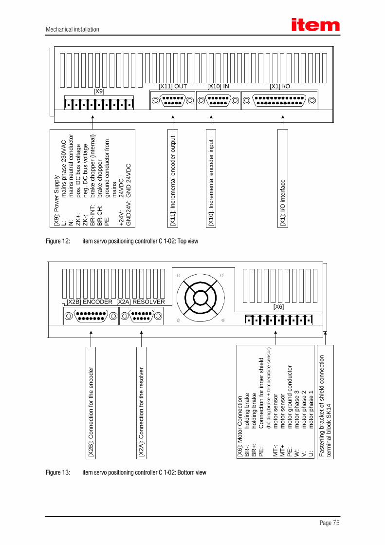
Mechanical installation
Page 75
[X1] I/O[X10] IN[X11] OUT[X9]
[X9]
: Pow
er S
uppl
yL:
mai
ns p
hase
230
VAC
N:
mai
ns n
eutra
l con
duct
orZK
+:po
s. D
C b
us v
olta
geZK
-:ne
g. D
C b
us v
olta
geBR
-INT:
brak
e ch
oppe
r (in
tern
al)
BR-C
H:
brak
e ch
oppe
rPE
:gr
ound
con
duct
or fr
om
mai
ns+2
4V:
24VD
CG
ND
24V:
GN
D 2
4VD
C
[X11
]: In
crem
enta
l enc
oder
out
put
[X10
]: In
crem
enta
l enc
oder
inpu
t
[X1]
: I/O
inte
rface
Figure 12: item servo positioning controller C 1-02: Top view
[X2A] RESOLVER[X6]
[X2B] ENCODER
[X6]
: Mot
or C
onne
ctio
nBR
-:ho
ldin
g br
ake
BR+:
hold
ing
brak
ePE
:C
onne
ctio
n fo
r inn
er s
hiel
d(h
oldi
ng b
rake
+ te
mpe
ratu
re s
enso
r)M
T-:
mot
or s
enso
rM
T+m
otor
sen
sor
PE:
mot
or g
roun
d co
nduc
tor
W:
mot
or p
hase
3V:
mot
or p
hase
2U
:m
otor
pha
se 1
[X2A
]: C
onne
ctio
n fo
r the
reso
lver
[X2B
]: C
onne
ctio
n fo
r the
enc
oder
Fast
enin
g br
acke
t of s
hiel
d co
nnec
tion
term
inal
blo
ck S
K14
Figure 13: item servo positioning controller C 1-02: Bottom view

Mechanical installation
Page 76
7.3 Mounting The item servo positioning controller C 1-Series has attachment lugs on the top and the bottom of the device. These lugs are used to mount the servo positioning controller vertically to a control cabinet plate. The lugs are part of the cooling body profile. This is why the best possible heat transfer to the control cabinet plate has to be ensured.
Recommended tightening torque for an M5 screw of property class 5.6: 2.8 Nm.
Please use M5 screws for the mounting of the item servo positioning controller C 1-02, C 1-05 und C 1-05.
R2,5
R5
261
mm
21 m
m
255,
5 m
m
28,8 mm
54,6 mm
4,5 mm
31,5
mm
247,
3 m
m
251
mm
R2,5 M4 flush head stud
Figure 14: item servo positioning controller C 1-Series: Mounting plate
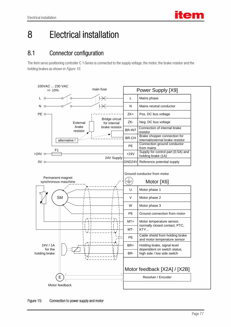
Electrical installation
Page 77
8 Electrical installation
8.1 Connector configuration The item servo positioning controller C 1-Series is connected to the supply voltage, the motor, the brake resistor and the holding brakes as shown in Figure 15.
Resolver / Encoder
SM
E
24V / 1Afor the
holding brake
Power Supply [X9]
Motor feedback [X2A] / [X2B]
24V Supply
Motor feedback
T
Permanent-magnetsynchronous maschine
Ground conductor from motor
100VAC ... 230 VAC+/- 10%
L
N
PE
+24V
0V
F1
Externalbrake
resistor
Bridge circuitfor internal
brake resistor
alternative !
L
Mains neutral conductor
ZK+ Pos. DC bus voltage
ZK- Neg. DC bus voltage
BR-INT Connection of internal brakeresistor
BR-CH Brake chopper connection forinternal/external brake resistor
PE Connection ground conductorfrom mains
+24V Supply for control part (0.5A) andholding brake (1A)
GND24V Reference potential supply
Mains phase
N
Motor [X6]U
Motor phase 2
W Motor phase 3
PE Ground connection from motor
MT+ Motor temperature sensor,normally closed contact, PTC,KTY...MT-
PE Cable shield from holding brakeand motor temperature sensor
BR+
BR-
Holding brake, signal leveldepentdent on switch status,high side / low side switch
Motor phase 1
V
main fuse
Figure 15: Connection to power supply and motor

Electrical installation
Page 78
The operation of the item servo positioning controller C 1-Series requires a 24V voltage supply source for the electronics supply, which is connected to the terminals +24V and GND24V.
The connection to the supply for the power output stage is either made to terminals L1 and N for AC supply or to ZK+ and ZK- for DC supply.
The motor is connected to terminals U, V and W. The motor temperature switch (analogue or digital) is connected to terminals MT+ and MT–, if it is lead into one cable together with the motor phases. If an analog temperature sensor is used in the motor (for example KTY81), the connection is realized via the encoder cable to [X2A] or [X2B].
The connection of the shaft encoder via the D-Sub connector to [X2A] / [X2B] is roughly shown in Figure 15.
The item servo positioning controller C 1-Series must be connected to ground with its PE connection.
The item C 1-Series must be completely wired first. Only then the operating voltages for the DC bus and the electronics may be switched on. In the case of inversed wiring of the operating voltage connections, excessive operating voltage or in the case of confusing the connections for operating voltage and motor the servo positioning controller will be damaged.
8.2 item C 1-Series complete system The complete item servo positioning controller C 1-Series system is shown in
Figure 16. The following components are required for using the servo positioning controller:
Main switch mains supply
Fault current protection switch (RCD), AC/DC sensitive 300mA (if this is required by an application)
Automatic circuit breaker
item servo positioning controller C 1-Series
Motor with motor cable
Mains cable
The parameterisation requires a PC with serial or USB connection.
A slow-blow (B16) single-phase automatic circuit breaker of 16 A has to be installed in the mains supply line.

Electrical installation
Page 79
Figure 16: Complete setup of the item C 1-Series with motor and PC

Electrical installation
Page 80
8.3 Connection: Power supply [X9] The item servo positioning controller C 1-Series receives its 24 VDC power supply for the control electronics via connector [X9].
The mains voltage supply is single-phase. As an alternative to AC feed or for the purpose of DC bus coupling a direct DC supply for the DC bus is possible.
8.3.1 Device side [X9]
C 1-02 and C 1-05 PHOENIX MINI-COMBICON MC1.5/9-G-5.08 BK
C 1-08 PHOENIX COMBICON MSTBA 2,5/9-G-5.08 BK
8.3.2 Counterplug [X9]
C 1-02 and C 1-05 PHOENIX MINI-COMBICON MC1.5/9-ST-5.08 BK
C 1-08 PHOENIX COMBICON MSTB 2,5/9-ST-5,08 BK
C 1-02 and C 1-05 PHOENIX MINI-COMBICON connector housing 12-pole, KGG-MC1,5/12 BK
C 1-08 PHOENIX COMBICON connector housing 12-pole, KGS-MSTB 2,5/9 BK
Coding to PIN 9 (GND24V)

Electrical installation
Page 81
8.3.3 Pin assignment [X9]
Table 33: Pin assignment: [X9]
Pin No. Denomination Values Specification
1 L 100 ... 230 VAC [± 10 %], 50 ... 60 Hz
Phase conductor
2 N Neutral conductor
3 ZK+ < 440 VDC Pos. DC bus voltage
4 ZK- GND_ZK Neg. DC bus voltage
5 BR-INT < 460 VDC Connection of internal brake resistor (bridge to BR-CH when using the internal resistor)
6 BR-CH < 460 VDC Brake chopper connection for internal brake resistor against BR-INT and external brake resistor against ZK+
7 PE PE Connection ground conductor from mains
8 +24V 24 VDC [± 20 %], 0,55 A *)
0,65 A *)
C 1-02
C 1-05 and C 1-08
Supply for control module
9 GND24V GND (0 VDC) Reference potential supply
*) Plus current consumption of a possibly connected holding brake and I/Os
8.3.4 Cable type and design [X9]
The mentioned cable denominations refer to cables by Lapp. They have proven effective and are successfully used in many applications. However, similar cables from other manufacturers, for example Lütze or Helukabel, may also be used.
For the 230 VAC supply:
LAPP KABEL ÖLFLEX-CLASSIC 110; 3 x 1.5 mm²

Electrical installation
Page 82
8.3.5 Connection notes [X9] PHOENIX
MINI-COMBICONat the X9
1
4
7
9
2
5
8
3
Power connector
6
PE
L
N
ZK+
GND24V
+24V
BR-INT
BR-CH
ZK-
PHOENIXCOMBICON
at the X9
externalbrake resistor
alternative !
Figure 17: Supply [X9]
C 1-02 and C 1-05: C 1-08:
PHOENIX MINI-COMBICON MC 1,5/ 9-ST-5,08 BK PHOENIX COMBICON MSTB 2,5/9-ST-5,08 BK
The item servo positioning controller C 1-Series has an internal brake chopper with brake resistor. For more brake power it is possible to connect an external brake resistor to the connector [X9].
If no external brake resistor is used, a bridge must be connected between PIN 5 and PIN 6 so that the DC bus precharge, when the mains power supply is “ON”, and the DC bus rapid discharge can function properly!

Electrical installation
Page 83
8.4 Connection: Motor [X6]
8.4.1 Device side [X6]
C 1-02 and C 1-05 PHOENIX MINI-COMBICON MC1.5/9-G-5.08 BK
C 1-08 PHOENIX COMBICON MSTBA 2,5/9-G-5.08 BK
8.4.2 Counterplug [X6]
C 1-02 and C 1-05 PHOENIX MINI-COMBICON MC1.5/9-ST-5.08 BK
C 1-08 PHOENIX COMBICON MSTB 2,5/9-ST-5,08 BK
C 1-02 and C 1-05 PHOENIX MINI-COMBICON connector housing 12-pole, KGG-MC1,5/12 BK
C 1-08 PHOENIX COMBICON connector housing 12-pole, KGS-MSTB 2,5/9 BK
Coding to PIN 1 (BR-)
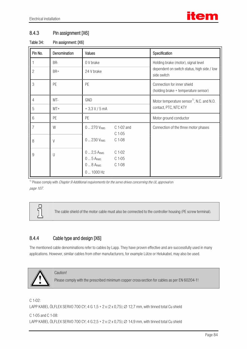
Electrical installation
Page 84
8.4.3 Pin assignment [X6]
Table 34: Pin assignment: [X6]
Pin No. Denomination Values Specification
1 BR- 0 V brake Holding brake (motor), signal level dependent on switch status, high side / low side switch
2 BR+ 24 V brake
3 PE PE Connection for inner shield (holding brake + temperature sensor)
4 MT- GND Motor temperature sensor1), N.C. and N.O. contact, PTC, NTC KTY 5 MT+ + 3,3 V / 5 mA
6 PE PE Motor ground conductor
7 W 0 ... 270 VRMS 0 ... 230 VRMS
0 ... 2,5 ARMS 0 ... 5 ARMS
0 ... 8 ARMS
0 ... 1000 Hz
C 1-02 and C 1-05 C 1-08 C 1-02 C 1-05 C 1-08
Connection of the three motor phases
8 V
9 U
1) Please comply with Chapter 9 Additional requirements for the servo drives concerning the UL approval on page 107.
The cable shield of the motor cable must also be connected to the controller housing (PE screw terminal).
8.4.4 Cable type and design [X6]
The mentioned cable denominations refer to cables by Lapp. They have proven effective and are successfully used in many applications. However, similar cables from other manufacturers, for example Lütze or Helukabel, may also be used.
Caution!
Please comply with the prescribed minimum copper cross-section for cables as per EN 60204-1!
C 1-02: LAPP KABEL ÖLFLEX SERVO 700 CY; 4 G 1,5 + 2 x (2 x 0,75); ∅ 12,7 mm, with tinned total Cu shield
C 1-05 and C 1-08: LAPP KABEL ÖLFLEX SERVO 700 CY; 4 G 2,5 + 2 x (2 x 0,75); ∅ 14,9 mm, with tinned total Cu shield

Electrical installation
Page 85
For highly flexible applications:
C 1-02: LAPP KABEL ÖLFLEX SERVO FD 755 P; 4 G 1,5 + 2 x (2 x 0,75) CP; ∅ 14,1 mm, with tinned total Cu shield for highly flexible use in drag chains
C 1-05 and C 1-08: LAPP KABEL ÖLFLEX SERVO FD 755 P; 4 G 2,5 + 2 x (2 x 0,75) CP; ∅ 15,1 mm, with tinned total Cu shield for highly flexible use in drag chains
8.4.5 Connection notes [X6]
PE (optional)
Motor Phase U resp. 1
Motor Phase V resp. 2
Motor Phase W resp. 3
BR-
BR+
MT+
MT-
Motor connector
PE (Motor)
Cable shield (optional)
1
4
7
9
2
5
8
3
6
Connector housing
Motor housing
PHOENIXMINI-COMBICON
at the X6
PHOENIXCOMBICON
at the X6
Figure 18: Motor connection [X6]
C 1-02 and C 1-05: C 1-08:
PHOENIX MINI-COMBICON MC 1,5/ 9-ST-5,08 BK PHOENIX COMBICON MSTB 2,5/9-ST-5,08 BK
Connect the inner shields to PIN 3; maximum length 40 mm.
Length of unshielded cores maximum 35 mm.
Connect total shield on controller side flat to PE terminal; maximum length 40 mm.
Connect total shield on motor side flat to connector or motor housing; maximum length 40 mm.
Via terminals ZK+ and ZK- the DC buses of several item servo positioning controller C 1-Series can be interconnected. The coupling of the DC bus is interesting for applications with high brake energies or if movements have to be carried out even in the case of power failure. For further information please refer to Application Note 67.
A holding brake can be connected to the terminals BR+ and BR- of the motor. The holding brake is fed by the servo positioning controller’s power supply. Note the maximum output current provided by the item servo positioning controller C 1-Series. A relay may have to be placed between the device and the holding brake as shown in Figure 19:

Electrical installation
Page 86
item C 1-Series
BR-
BR+
1
2+2
4 V
Pow
er su
pply
GND
Pow
er su
pply
Resistor and capacitor for spark extinguishing
Motor withholding brake
+24
VHo
ldin
g br
ake
GND
Hold
ing
brak
e
Free-wheeling diode
Figure 19: Connecting a holding brake with high current draw (> 1A) to the device
The switching of inductive direct current via relay produces strong currents and sparking. For interference suppression we recommend integrated RC suppressor elements, for example by Evox RIFA, denomination: PMR205AC6470M022 (RC element with 22 Ω in series with 0.47 µF).

Electrical installation
Page 87
8.5 Connection: I/O communication [X1] The following Figure 20 shows the principle function of the digital and analog inputs and outputs. The item servo positioning controller C 1-Series is shown on the right hand side, the control system connection on the left. The cable design is also visible.
The item servo positioning controller C 1-Series features two potential ranges:
Analog inputs and outputs:
All analog inputs and outputs refer to AGND. AGND is internally connected with GND, the reference potential for the control module with µC and AD converters in the controller. This potential range is galvanically separated from the 24 V range and from the DC bus.
24 V inputs and outputs:
These signals refer to the 24 V supply voltage of the item servo positioning controller C 1-Series which is fed via [X9], and separated from the reference potential of the control module by means of optocouplers.

Electrical installation
Page 88
24
11
19
6
18
14
1
5
14
17
4
163
152
13DOUT 3
DIN 9
DOUT 0
DIN 0
GND 24 V
+24 VDC
+VREF
AMON 0
AIN 1
AIN 0
Pin No.X1
AMON 1
AIN 2
#AIN 0
AGND
AGND
DOUT x
GND 24 V
+24 VDC
+24 VDC
GND
GND 24 V
PEPE
100 mAmax !
100 mAmax !
Connector housing
+VREF
AIN 0
#AIN 0
AGND
AIN 1 / AIN 2
AGND
+15 V
AGND
AGND
AMON x
AGND
GND AGND
DIN x
GND 24 VGND
Control system item C 1-Series
Figure 20: Basic circuit diagram connector [X1]
The item servo positioning controller C 1-Series comprises one differential (AIN 0) and two single-ended analog inputs, designed for input voltages within a range of ±10V. The inputs AIN 0 and #AIN 0 are lead to the control via twisted cables (twisted pair design).
If the control comprises single-ended outputs, the output is connected to AIN 0 and #AIN 0 is put on the reference potential of the control. If the control has differential outputs, they are to be connected 1:1 to the differential inputs of the item servo positioning controller C 1-Series.

Electrical installation
Page 89
The reference potential AGND is connected to the reference potential of the control. This is necessary in order to prevent the differential input of the item servo positioning controller C 1-Series from being overridden by high "common-mode interference".
There are two analog monitor outputs with output voltages in the range of ± 10 V and an output for a reference voltage of + 10 V. These outputs can be led to the superimposed control, the reference potential AGND must be carried along. If the control has differential inputs, the "+"-input of the control is connected to the output of the item servo positioning controller C 1-Series and "-"-input of the control with AGND.
8.5.1 Device side [X1]
D-SUB connector, 25-pole, female
8.5.2 Counterplug [X1]
D-SUB connector, 25-pole, male
Housing for 25-pole D-SUB connector with bolting screws 4/40 UNC

Electrical installation
Page 90
8.5.3 Pin assignment [X1]
Table 35: Pin assignment: I/O communication [X1]
Pin No. Denomination Values Specification
1 AGND 0 V Shield for analog signals, AGND
14 AGND 0 V Reference potential for analog signals
2 AIN 0 UIn = ± 10 V RI ≥ 30 kΩ
Setpoint input 0, differential, max. 30 V input voltage
15 #AIN 0
3 AIN 1 UIn = ± 10 V RI ≥ 30 kΩ
Setpoint inputs 1 and 2, single ended, max. 30 V input voltage 16 AIN 2
4 +VREF + 10 V Reference output for setpoint potentiometer
17 AMON 0 ± 10 V Analog monitor output 0
5 AMON 1 ± 10 V Analog monitor output 1
18 +24V 24 V / 100 mA Auxiliary voltage for IOs at X1
6 GND24 Reference GND Reference potential for digital I/Os
19 DIN 0 POS Bit 0 Target selection positioning Bit 0
7 DIN 1 POS Bit 1 Target selection positioning Bit 1
20 DIN 2 POS Bit 2 Target selection positioning Bit 2
8 DIN 3 POS Bit 3 Target selection positioning Bit3
21 DIN 4 FG_E Power stage enable
9 DIN 5 FG_R Input controller enable
22 DIN 6 END 0 Input end switch 0 (locks n < 0)
10 DIN 7 END 1 Input end switch 1 (locks n > 0)
23 DIN 8 START Input for positioning start
11 DIN 9 SAMP High-speed input
24 DOUT 0 / READY 24 V / 100 mA Output operational
12 DOUT 1 24 V / 100 mA Output freely programmable
25 DOUT 2 24 V / 100 mA Output freely programmable
13 DOUT 3 24 V / 100 mA Output freely programmable

Electrical installation
Page 91
8.5.4 Cable type and design [X1]
The mentioned cable denominations refer to cables by Lapp. They have proven effective and are successfully used in many applications. However, similar cables from other manufacturers, for example Lütze or Helukabel, may also be used.
LAPP KABEL UNITRONIC LiYCY (TP); 25 x 0,25mm²; ∅ 10,7 mm
Figure 20 shows the cable between the item servo positioning controller C 1-Series and the control. The cable shown has two cable shields.
The outer cable shield is connected on both sides to PE. Inside the servo positioning controller the connector housing of the D-Sub connector is connected to PE. When using metal D-Sub connector housings the cable shield is simply squeezed underneath the strain relief clamp.
Often, an unshielded cable is sufficient for the 24 V signals. In heavily disturbed surroundings or in the case of long cables (l > 2 m) between the control and the item servo positioning controller C 1-Series item recommends the use of shielded cables.
In spite of the differential design of the analog inputs of the item C 1-Series the cables should not be unshielded, since interferences, for example due to switching contactors or power stage interferences of the converters can reach high amplitudes. They couple into the analog signals and cause common-mode interference, which may lead to deviation of the analog measured values.
In the case of limited cable lengths (l < 2 m, wiring inside control cabinet) the outer dual-sided PE shield is enough to guarantee undisturbed operation.
For optimal interference suppression on the analog signals the cores for the analog signals are to be shielded together and separate from others. This internal cable shield is connected to AGND (Pin 1 or 14) on one side of the item C 1-Series. It can be connected on both sides in order to establish a connection between the reference potentials of the control and the item servo positioning controller C 1-Series. Pins 1 and 14 are directly connected to each other inside the controller.
8.5.5 Connection notes [X1]
The digital inputs are designed for control voltages of 24 V. Due to the high signal level a higher interference immunity of these inputs is already guaranteed. The item servo positioning controller C 1-Series provides a 24 V auxiliary voltage, which may be loaded with a maximum of 100 mA. This way the inputs can be activated directly via switches. Activation via the 24 V outputs of a PLC is, of course, also possible.
The digital outputs are designed as so-called "high-side switches ". That means that the 24 V of the item servo positioning controller C 1-Series are actively switched through to the output. Loads such as lamps, relays, and so on are thus switched from the output to GND24. The four outputs DOUT 0 to DOUT 3 can be loaded with a maximum of 100mA each. The outputs can also be lead directly to 24 V inputs of a PLC.

Electrical installation
Page 92
8.6 Connection: Resolver [X2A]
8.6.1 Device side [X2A]
1 D-SUB connector, 9-pole, female
8.6.2 Counterplug [X2A]
D-SUB connector, 9-pole, male
Housing for 9-pole D-SUB connector with bolting screws 4/40 UNC
8.6.3 Pin assignment [X2A]
Table 36: Pin assignment: [X2A]
Pin No. Denomination Values Specification
1 S2 3,5 Veff / 5-10 kHz
Ri > 5 kΩ
SINE trace signal, differential
6 S4
2 S1 3,5 Veff / 5-10 kHz
Ri > 5 kΩ
COSINE trace signal, differential
7 S3
3 AGND 0 V Shield for signal pairs (inner shield)
8 MT- GND (0 V) Reference potential temperature sensor
4 R1 7 Veff / 5-10 kHz IA ≤ 150 mAeff
Carrier signal for resolver
9 R2 GND (0 V)
5 MT+ +3,3 V / Ri = 2 kΩ Motor temperature sensor, normally closed contact, PTC, KTY
The outer cable shield of the angle encoder cable must additionally be applied to the mounting plate of the controller housing over a large contact area with the aid of the shield connection clamp SK14.
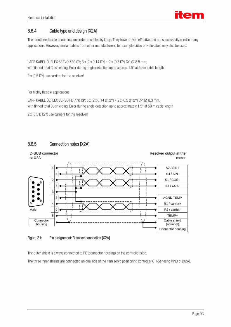
Electrical installation
Page 93
8.6.4 Cable type and design [X2A]
The mentioned cable denominations refer to cables by Lapp. They have proven effective and are successfully used in many applications. However, similar cables from other manufacturers, for example Lütze or Helukabel, may also be used.
LAPP KABEL ÖLFLEX SERVO 720 CY; 3 x (2 x 0,14 DY) + 2 x (0,5 DY) CY; ∅ 8.5 mm, with tinned total Cu shielding, Error during angle detection up to approx. 1.5° at 50 m cable length
2 x (0,5 DY) use carriers for the resolver!
For highly flexible applications:
LAPP KABEL ÖLFLEX SERVO FD 770 CP; 3 x (2 x 0,14 D12Y) + 2 x (0,5 D12Y) CP; ∅ 8.3 mm, with tinned total Cu shielding, Error during angle detection up to approximately 1.5° at 50 m cable length
2 x (0.5 D12Y) use carriers for the resolver!
8.6.5 Connection notes [X2A]
2
3
4
5
6
7
8
1
9
Connectorhousing
1
59
6
Cable shield(optional)
S3 / COS-
S1 / COS+
S2 / SIN+
AGND TEMP
R1 / carrier+
R2 / carrier-
TEMP+
S4 / SIN-
Resolver output at themotor
D-SUB connectorat X2A
Male
Connector housing Figure 21: Pin assignment: Resolver connection [X2A]
The outer shield is always connected to PE (connector housing) on the controller side.
The three inner shields are connected on one side of the item servo positioning controller C 1-Series to PIN3 of [X2A].

Electrical installation
Page 94
8.7 Connection: CAN-Bus [X4]
8.7.1 Device side [X4]
D-SUB connector, 9-pole, female
8.7.2 Counterplug [X4]
D-SUB connector, 9-pole, male
Housing for 9-pole D-SUB connector with bolting screws 4/40 UNC
8.7.3 Pin assignment [X4]
Table 37: Pin assignment: CAN-Bus [X4]
Pin No. Denomination Values Specification
1 Not occupied
6 GND 0 V CAN-GND, galvanically connected to GND in controller
2 CANL *) CAN-Low signal line
7 CANH *) CAN-High signal line
3 GND 0 V See Pin no. 6
8 Not occupied
4 Not occupied
9 Not occupied
5 Shield PE Connection for cable shield
*) External terminating resistor 120 Ω required on both ends of the bus. If the bus ends are not formed by item C 1-Series servo positioning controllers with integrated terminating resistors, we recommend using metal film resistors with a 1 % tolerance of type 0207, for example made by BCC, order no.: 232215621201.
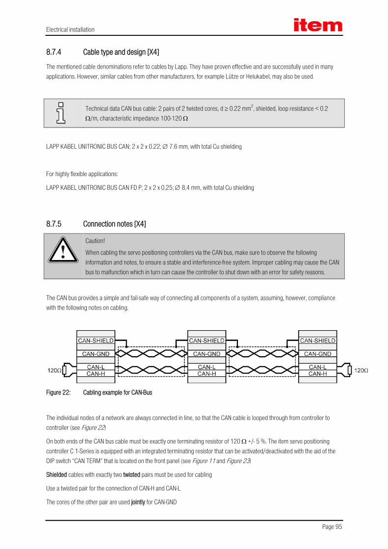
Electrical installation
Page 95
8.7.4 Cable type and design [X4]
The mentioned cable denominations refer to cables by Lapp. They have proven effective and are successfully used in many applications. However, similar cables from other manufacturers, for example Lütze or Helukabel, may also be used.
Technical data CAN bus cable: 2 pairs of 2 twisted cores, d ≥ 0.22 mm2, shielded, loop resistance < 0.2 Ω/m, characteristic impedance 100-120 Ω
LAPP KABEL UNITRONIC BUS CAN; 2 x 2 x 0.22; ∅ 7.6 mm, with total Cu shielding
For highly flexible applications:
LAPP KABEL UNITRONIC BUS CAN FD P; 2 x 2 x 0,25; ∅ 8,4 mm, with total Cu shielding
8.7.5 Connection notes [X4]
Caution!
When cabling the servo positioning controllers via the CAN bus, make sure to observe the following information and notes, to ensure a stable and interference-free system. Improper cabling may cause the CAN bus to malfunction which in turn can cause the controller to shut down with an error for safety reasons.
The CAN bus provides a simple and fail-safe way of connecting all components of a system, assuming, however, compliance with the following notes on cabling.
Figure 22: Cabling example for CAN-Bus
The individual nodes of a network are always connected in line, so that the CAN cable is looped through from controller to controller (see Figure 22)
On both ends of the CAN bus cable must be exactly one terminating resistor of 120 Ω +/- 5 %. The item servo positioning controller C 1-Series is equipped with an integrated terminating resistor that can be activated/deactivated with the aid of the DIP switch “CAN TERM” that is located on the front panel (see Figure 11 and Figure 23)
Shielded cables with exactly two twisted pairs must be used for cabling
Use a twisted pair for the connection of CAN-H and CAN-L
The cores of the other pair are used jointly for CAN-GND

Electrical installation
Page 96
The shield of the cable is led to the CAN shield connections for all nodes
For suitable and item-recommended cables please refer to chapter 8.7.4 Cable type and design [X4]
We advise against the use of plug adaptors for CAN bus cabling. Should this be necessary nonetheless, make sure to use metal connector housings to connect the cable shield
In order to keep interferences as low as possible make sure that
Motor cables are not installed parallel to signal lines
Motor cables comply with item specifications
Motor cables are properly shielded and grounded
For further information on interference-free CAN bus cabling, please refer to the Controller Area Network protocol specification, Version 2.0 by Robert Bosch GmbH, 1991
integratedterminating resistor
120 Ω
X4, Pin 7(CAN-H)
X4, Pin 2(CAN-L)
DIP switchCAN TERM
Figure 23: Integrated CAN terminating resistor

Electrical installation
Page 97
8.8 Connection: RS232/COM [X5]
8.8.1 Device side [X5]
D-SUB connector, 9-pole, male
8.8.2 Counterplug [X5]
D-SUB connector, 9-pole, female
Housing for 9-pole D-SUB connector with bolting screws 4/40 UNC
8.8.3 Pin assignment [X5]
Table 38: Pin assignment: RS232 interface [X5]
Pin No. Denomination Values Specification
1 Not occupied
6 Not occupied
2 RxD 10 V / RI > 2 kΩ Receive line, RS232 specification
7 - - Not occupied
3 TxD 10 V / RA < 2 kΩ Transmitting line, RS232 specification
8 Not occupied
4 +RS485 reserved for optional RS485 use
9 -RS485 reserved for optional RS485 use
5 GND 0 V Interfaces GND, galvanically connected to GND DGND

Electrical installation
Page 98
8.8.4 Cable type and design [X5]
Interface cable for serial interface (null modem), 3-core.
8.8.5 Connection notes [X5]
D-SUB connectorat X5
PC
2
3
4
5
6
7
8
1
9
Connector housing
1
59
6
Connector housing
2
3
4
5
6
7
8
1
9
1
59
6
Female Female
Figure 24: Pin assignment: RS232 null modem cable [X5]

Electrical installation
Page 99
8.9 Connection: USB [X19]
8.9.1 Device side [X19]
USB female, type B
8.9.2 Counterplug [X19]
USB male, type B
8.9.3 Pin assignment [X19]
Table 39: Pin assignment: USB interface [X19]
Pin No. Denomination Values Specification
1 VCC + 5 VDC
2 D- Data -
3 D+ Data +
4 GND GND
Figure 25: Pin assignment: USB interface [X19], front view
8.9.4 Cable type and design [X19]
Interface cable for the USB interface, 4 cores, shielded and twisted.
In order to set up a USB connection, it is mandatory to use a twisted and shielded (4-core) cable since, otherwise, the transmission may be subject to interferences. In addition, it must be ensured that the cable has a wave impedance of 90 Ω.
Electrical installation
Page 100
8.10 SD/MMC card
8.10.1 Supported card types
SD
SDHC
MMC
8.10.2 Supported functions
Load a parameter set (DCO file)
Save the current parameter set (DCO file)
Load a firmware file
8.10.3 Supported file systems
FAT12
FAT16
FAT32
8.10.4 File names
Only file and directory names according to the 8.3 standard are supported.
8.3 file and directory names have at most eight characters (letters or numbers) followed by a period “.” and a filename extension of at most three characters. File and directory names may only consist of upper-case characters and numbers.

Electrical installation
Page 101
8.10.5 Pin assignment SD/MMC card
Table 40: Pin assignment: SD card
Pin No Denomination SD Mode SPI Mode
1 DATA3/CS Data Line 3 (Bit 3) Chip Select
2 CMD/DI Command/Response Host to Card Commands and Data
3 Vss1 Supply Voltage Ground Supply Voltage Ground
4 Vcc Supply Voltage Supply Voltage
5 CLK Clock Clock
6 Vss2 Supply Voltage Ground Supply Voltage Ground
7 DAT0/DO Data Line 0 (Bit 0) Card to Host Data and Status
8 DAT1 Data Line 1 (Bit 1) reserved
9 DAT2 Data Line 2 (Bit 2) reserved
Table 41: Pin assignment: MMC card
Pin No Denomination SD Mode SPI Mode
1 RES/CS Not connected or Always „1“ Chip Select
2 CMD/DI Command/Response Host to Card Commands and Data
3 Vss1 Supply Voltage Ground Supply Voltage Ground
4 Vcc Supply Voltage Supply Voltage
5 CLK Clock Clock
6 Vss2 Supply Voltage Ground Supply Voltage Ground
7 DAT/DO Data 0 Card to Host Data and Status
Electrical installation
Page 102
Figure 26: Pin assignment: SC/MMC card
8.10.6 BOOT-DIP-Switch
During a restart/reset, the BOOT-DIP-Switch is used to determine whether to perform a firmware download from the SD/MMC card or not.
BOOT-DIP-Switch in position “ON” firmware download requested
BOOT-DIP-Switch in position “OFF” firmware download not requested
When there is no SD/MMC card in the card slot of the servo positioning controller and the BOOT-DIP-Switch is in the position “ON” (firmware download requested), the error 29-0 is triggered after a restart/reset. This error stops all further performances. This means that there is no communication possible via the serial interface (RS232) or USB.

Electrical installation
Page 103
8.11 Notes on safe and EMC-compliant installation
8.11.1 Definitions and terms
Electromagnetic compatibility (EMC) or electromagnetic interference (EMI) includes the following requirements:
Sufficient immunity of an electrical installation or an electrical device against outside electrical, magnetic or electromagnetic interferences via cables or the ambient
Sufficiently small unwanted emission of electrical, magnetic or electromagnetic interference from an electrical installation or an electrical device to other devices in the vicinity via cables or the ambient
8.11.2 General information on EMC
The interference emission and interference immunity of a device always depend on the entire drive concept consisting of the following components:
Voltage supply
Servo positioning controller
Motor
Electro mechanics
Execution and type of wiring
Superimposed control
In order to increase interference immunity and to decrease interference emissions the item servo positioning controller C 1-Series already comprises output chokes and mains filters, so that it can be operated without additional shielding and filtering devices in most applications.
The item servo positioning controller C 1-Series are certified as per the product standard EN 61800-3 for electrical drive systems.
In most cases no external filtering is required (see below).
The conformity certificate for EMC directive 2004/108/EC is available from the manufacturer.
Caution!
This product can cause high-frequency interference in residential areas, which could require measures for radio interference suppression.
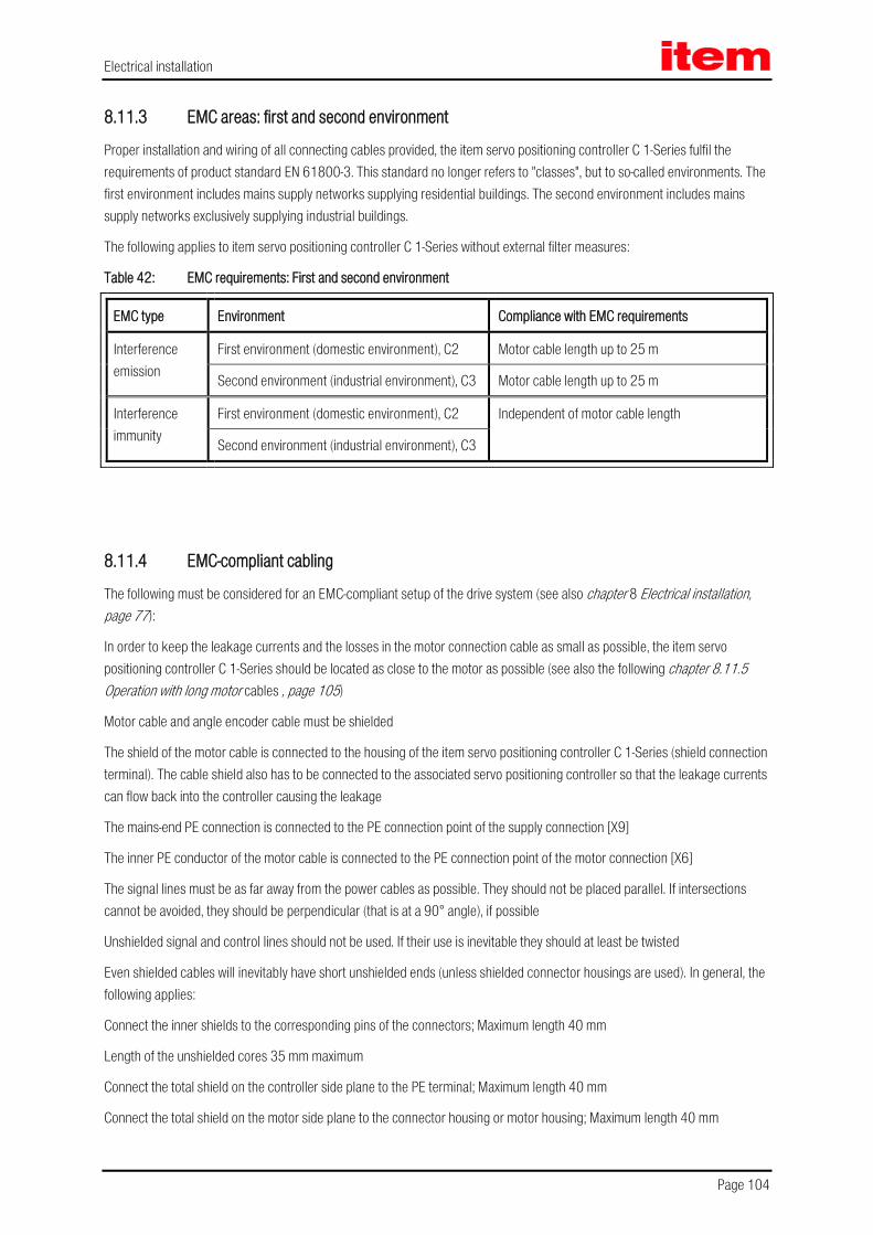
Electrical installation
Page 104
8.11.3 EMC areas: first and second environment
Proper installation and wiring of all connecting cables provided, the item servo positioning controller C 1-Series fulfil the requirements of product standard EN 61800-3. This standard no longer refers to "classes", but to so-called environments. The first environment includes mains supply networks supplying residential buildings. The second environment includes mains supply networks exclusively supplying industrial buildings.
The following applies to item servo positioning controller C 1-Series without external filter measures:
Table 42: EMC requirements: First and second environment
EMC type Environment Compliance with EMC requirements
Interference emission
First environment (domestic environment), C2 Motor cable length up to 25 m
Second environment (industrial environment), C3 Motor cable length up to 25 m
Interference immunity
First environment (domestic environment), C2 Independent of motor cable length
Second environment (industrial environment), C3
8.11.4 EMC-compliant cabling
The following must be considered for an EMC-compliant setup of the drive system (see also chapter 8 Electrical installation, page 77):
In order to keep the leakage currents and the losses in the motor connection cable as small as possible, the item servo positioning controller C 1-Series should be located as close to the motor as possible (see also the following chapter 8.11.5 Operation with long motor cables , page 105)
Motor cable and angle encoder cable must be shielded
The shield of the motor cable is connected to the housing of the item servo positioning controller C 1-Series (shield connection terminal). The cable shield also has to be connected to the associated servo positioning controller so that the leakage currents can flow back into the controller causing the leakage
The mains-end PE connection is connected to the PE connection point of the supply connection [X9]
The inner PE conductor of the motor cable is connected to the PE connection point of the motor connection [X6]
The signal lines must be as far away from the power cables as possible. They should not be placed parallel. If intersections cannot be avoided, they should be perpendicular (that is at a 90° angle), if possible
Unshielded signal and control lines should not be used. If their use is inevitable they should at least be twisted
Even shielded cables will inevitably have short unshielded ends (unless shielded connector housings are used). In general, the following applies:
Connect the inner shields to the corresponding pins of the connectors; Maximum length 40 mm
Length of the unshielded cores 35 mm maximum
Connect the total shield on the controller side plane to the PE terminal; Maximum length 40 mm
Connect the total shield on the motor side plane to the connector housing or motor housing; Maximum length 40 mm

Electrical installation
Page 105
DANGER!
For safety reasons, all PE ground conductors must be connected prior to initial operation.
The EN 61800-5-1 regulations for protective earthing must be complied with during installation!
8.11.5 Operation with long motor cables
Compliance with the EMC standard EN 61800-3 is only guaranteed for motor cable lengths of up to 25 m. For cable lengths beyond this a new measurement of the interference emission may possibly be required.
In applications involving long motor cables and/or unsuitable motor cables with an inadvertently high cable capacity, the filters may be thermally overloaded. To avoid such problems we highly recommend the following procedure for applications that require long motor cables:
With cable lengths of more than 25 m use only cables with a capacitance per unit length between the motor phase and the shield of less than 150 pF/m! (Please contact the motor cable supplier, if necessary)
For motor cable lengths of more than 25 m and up to 50 m the following derating applies regardless of the EMC qualification (see also Table 7, Technical data: Cable specifications):
PWM frequency up to 5 kHz 5,5 kHz 6 kHz 7 kHz 8 kHz
Max. motor cable length 50 m 45 m 40 m 35 m 30 m
Electrical installation
Page 106
8.11.6 ESD protection
Caution!
Unassigned D-Sub connectors may cause damage to the device or other parts of the system due to ESD (electrostatic discharge).
To prevent such discharge, protective caps are available (for example Spoerle).
The item servo positioning controller C 1-Series has been designed to provide high interference immunity. For that reason, some individual functional blocks are electrically isolated. Inside the device the signals are transmitted via optocouplers.
The following isolated areas are distinguished:
Power module with DC bus and mains input
Control electronics with processing of analog signals
24 V supply and digital inputs and outputs

Additional requirements for the servo drives concerning the UL approval
Page 107
9 Additional requirements for the servo drives concerning the UL approval
This chapter gives further information concerning the UL approval of the C 1-02, C 1-05 and C 1-08.
9.1 Circuit protection
In case of a required UL-certification the following data for the main fuse are to be considered:
Listed Circuit Breaker according to UL 489, rated 277 Vac, 16 A, SCR 10 kA
9.2 Wiring and environment regards Use 60/75 or 75°C copper (CU) wire only.
The terminal tightening torque is 0.22...0.25 Nm.
To be used in a Pollution Degree 2 environment only.
9.3 Motor temperature sensor
Motor overtemperature sensing is not provided by the drive according to UL.
When a UL-certification is required, then in order to prevent motor overtemperatures the servo drives may only be operated in connection with motors that are provided with an integrated motor temperature sensor. The sensor has to be connected to the servo drive and the temperature monitoring has to be activated accordingly on the software side.

Initial operation
Page 108
10 Initial operation
10.1 General notes on connection
Since the laying of the connection cables is very important in terms of EMC, make sure to comply with the previous chapter 8.11.4 EMC-compliant cabling (page 104)!
DANGER!
Noncompliance with chapter 2 Safety notes for electrical drives and controllers (page 16) may result in property damage, person injury, electric shock or in extreme cases in death.
10.2 Tools / material Screwdriver for slotted head screws size 1
Serial interface cable
Angle encoder cable
Motor cable
Power supply cable
Controller enabling cable
10.3 Connecting the motor Plug the connector of the motor cable into the corresponding socket of the motor and screw tight
Plug PHOENIX connector into socket [X6] of the servo positioning controller
Connect the PE line of the motor to the PE socket
Plug the connector of the encoder cable into the encoder output socket of the motor and screw tight
Plug the D-Sub connector into the socket [X2A] Resolver or [X2B] Encoder of the servo positioning controller and fasten the bolting screws
Apply the shield of the motor or angle encoder cable over a large contact area with the aid of the shield connection clamp SK14
Check all connections again

Initial operation
Page 109
10.4 Connecting the item servo positioning controller C 1-Series to the power supply
Make sure that the power supply has been switched off
Plug the PHOENIX connector into socket [X9] of the servo positioning controller
Connect the PE line of the mains to the PE socket
Connect the 24 V connections to a suitable power supply unit
Make mains supply connections
Check all connections again
10.5 Connecting the PC (serial interface) Plug the D-Sub connector of the serial interface cable into the socket for the serial interface of the PC and fasten the bolting screws
Plug the D-Sub connector of the serial interface cable into the socket [X5] RS232/COM of the item servo positioning controller C 1-Series and fasten the bolting screws
Check all connections again
10.6 Connecting the PC (USB interface, alternative) Plug the plug A of the USB interface cable into the socket for the USB interface of the PC
Plug the plug A of the USB interface cable into the socket [X19] USB of the item servo positioning controller C 1-Series
Check all of the plug-and-socket connections once more
10.7 Checking operability Make sure the controller enabling switch is turned off
Switch on the power supply of all devices. The READY / ERROR LED on the front of the servo positioning controller should now be active green
If the READY LED does not light green but red, there is a malfunction. If the seven-segment display indicates a number sequence, it is displaying an error message. You have to take care of the corresponding problem. In this case please continue with chapter 11.2.2 Error messages (page 114). If the device displays nothing, follow these steps:
Switch off the power supply
Wait 5 minutes, so the DC bus can discharge
Check all connection cables
Check the functionality of the 24 V power supply
Switch the power supply back on

Service functions and error messages
Page 110
11 Service functions and error messages
11.1 Protection and service functions
11.1.1 Overview
The item servo positioning controller C 1-Series has a powerful sensor analysis, which monitors the proper functioning of the controller, power output stage, motor and communication with the outside world. All occurring errors are stored in an internal error memory. Most errors will cause the controller unit to shut down the servo positioning controller and the power output stage. They can only be switched on again after the error memory has been deleted by acknowledging the error and after the error has been eliminated or no longer exists.
A powerful sensor analysis and monitoring function provides operational safety:
Measuring of motor temperature
Measuring of power module temperature
Detection of ground faults (PE)
Detection of connections between two motor phases
Detection of overvoltage in the DC bus
Detection of errors with the internal voltage supply
Failure of the supply voltage.
If the 24 V DC supply voltage fails, approx. 20 ms remain to save parameters and shut down the controller properly for example.
11.1.2 Overcurrent and short-circuit monitoring
The overcurrent and short-circuit monitoring detects short-circuits between two motor phases as well as short-circuits at the motor output terminals against the positive and negative reference potential of the DC bus and against PE. If the error monitoring detects an overcurrent, the power output stage will be shut down immediately to guarantee the ability to withstand short-circuits.

Service functions and error messages
Page 111
11.1.3 Overvoltage monitoring for the DC bus
This monitor responds, if the DC bus voltage exceeds the operating voltage range. The power output stage will be shut down.
11.1.4 Temperature monitoring of the heat sink
The heat sink temperature of the power output stage is measured with a linear temperature sensor. The temperature limit varies from device to device.
11.1.5 Monitoring of the motor
The item servo positioning controller C 1-Series has the following protective functions to monitor the motor and the connected encoder:
Monitoring of the encoder: An error of the shaft encoder leads to the shut-down of the power output stage. In the case of resolvers, for example the encoder signal is monitored. In the case of incremental encoders the commutation signals are checked. Other “intelligent” encoders provide further means of error detection.
Measurement and monitoring of the motor temperature: The item servo positioning controller C 1-Series has a digital and analogue input for measuring and monitoring the motor temperature. The analog signal detection also supports non-linear sensors. The following temperature sensors can be selected:
At [X2A], [X2B] and [X6]: Input for PTCs, NTCs, normally closed contacts, normally open contacts and analog sensors, type KTY.
11.1.6 I²t monitoring
The item servo positioning controller C 1-Series comprises an I²t monitoring to limit the average power loss in the power output stage and in the motor. Since the occurring power loss in the power electronics and in the motor in the worst case increases square with the current, the squared current value is assumed as the measure for the power loss.

Service functions and error messages
Page 112
11.1.7 Power monitoring for the brake chopper
Power monitoring for the internal brake resistor is implemented in the operating software.
When the power monitoring “I²t brake chopper” reaches 100% the power of the internal brake resistor is switched back to the rated output power.
11.1.8 I²t monitoring for the PFC stage
I²t monitoring for the PFC is implemented in the operating software (except the C 1-08).
11.1.9 Initial operation status
Servo positioning controllers, which are sent to item for service, will be equipped with a different firmware and other parameters for testing purposes.
Before the next initial operation at the customer the item servo positioning controller C 1-Series must be parameterized again. The parameterisation software item Motion Soft® queries the initial operation status and asks the user to parameterize the servo positioning controller. At the same time the device shows an “A” on the seven-segment display to indicate that it is ready but not yet parameterized.
11.1.10 Rapid discharge of the DC bus
If the system detects a failure of the mains supply, the DC bus is rapidly discharged within the safety period in accordance with EN 60204-1.
Delayed activation of the brake chopper according to power classes in the case of parallel operation and mains supply failure ensures that the main energy during rapid discharge of the DC bus is taken over through the braking resistors of the higher power classes.
11.1.11 Operating hours counter
An operating hours counter is implemented, which has been designed for at least 200 000 operating hours. The operating hours counter is displayed in the parameterisation software item Motion Soft®.
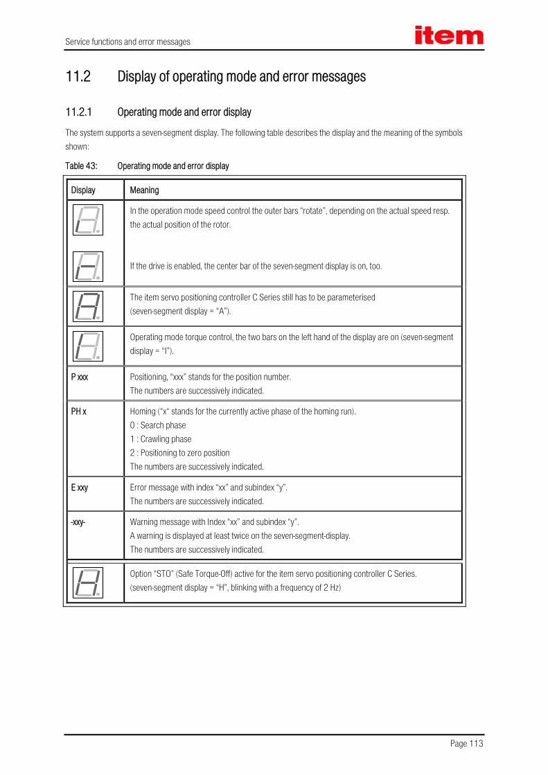
Service functions and error messages
Page 113
11.2 Display of operating mode and error messages
11.2.1 Operating mode and error display
The system supports a seven-segment display. The following table describes the display and the meaning of the symbols shown:
Table 43: Operating mode and error display
Display Meaning
In the operation mode speed control the outer bars “rotate”, depending on the actual speed resp. the actual position of the rotor. If the drive is enabled, the center bar of the seven-segment display is on, too.
The item servo positioning controller C Series still has to be parameterised (seven-segment display = “A”).
Operating mode torque control, the two bars on the left hand of the display are on (seven-segment display = “I”).
P xxx Positioning, “xxx” stands for the position number. The numbers are successively indicated.
PH x Homing (“x“ stands for the currently active phase of the homing run). 0 : Search phase 1 : Crawling phase 2 : Positioning to zero position The numbers are successively indicated.
E xxy Error message with index “xx” and subindex “y”. The numbers are successively indicated.
-xxy- Warning message with Index “xx” and subindex “y”. A warning is displayed at least twice on the seven-segment-display. The numbers are successively indicated.
Option “STO” (Safe Torque-Off) active for the item servo positioning controller C Series. (seven-segment display = “H”, blinking with a frequency of 2 Hz)

Service functions and error messages
Page 114
11.2.2 Error messages
If an error occurs, the item servo positioning controller C Series will cyclically show an error message in its seven-segment display. The error message is comprised of an E (for Error), a main index (xx) and a sub index (y), for example: E 0 1 0.
Warnings have the same code numbers as error messages. As a distinguishing feature, warnings have a centre bar before and after the number, for example - 1 7 0 -.
The following Table 44 Error messages summarizes the meaning of the messages and the corresponding measures.
The error messages with the main index 00 do not reflect run time errors. They contain information and in general there are no measures required by the user. They appear only in the error buffer and are not displayed on the seven-segment display.

Service functions and error messages
Page 115
Table 44: Error messages
Error message Meaning of the error message Measures
Main index
Sub index
00 0 Invalid error Information: Only for connected service module. An invalid (corrupted) entry in the error buffer has been marked by this error number.
The system time entry is set to 0.
No measures required.
1 Invalid error detected and corrected Information: Only for connected service module. An invalid (corrupted) error entry has been detected in the permanent event memory and corrected.
2 Error cleared Information: The active errors have been acknowledged.
No measures required.
4 Serial number/device type changed (module change)
Information: Only for connected service module. An exchangeable error buffer has been plugged into another device.
No measures required.
7 Log add-on: Permanent event memory and FSM module
Information: Entry in permanent event memory. “An additional record was found.”
No measures required.
8 Servo drive switched on Information: Entry in permanent event memory.
No measures required.
9 Servo drive safety parameters revised Information: Entry in permanent event memory.
No measures required.
11 FSM: Module change (previous type): Permanent event memory and FSM module
Information: Entry in permanent event memory.
No measures required.
12 FSM: Module change (current type): Permanent event memory and FSM module
Information: Entry in permanent event memory.
No measures required.
01 0 Stack overflow Incorrect firmware?
If necessary, reload the standard firmware.
Contact the Technical Support.

Service functions and error messages
Page 116
Error message Meaning of the error message Measures
Main index
Sub index
02 0 Undervoltage of the DC bus circuit Error priority set too high?
Check the power supply.
Check (measure) the DC bus circuit voltage.
Check the response threshold of the DC bus circuit monitoring system.
03 0 Motor overtemperature (analogue)
Motor too hot? Check the parameterization (current controller, current limits).
Suitable sensor?
Sensor defective?
Check the parameterization of the sensor or the characteristic curve of the sensor.
If the error occurs also when the sensor is bypassed, return the device to our sales partner.
1 Motor overtemperature (digital)
2 Motor Overtemperature (analogue): wire break
Check the connecting cables of the temperature sensor (broken wire).
Check the parameterisation of wire break detection system (threshold value).
3 Motor overtemperature (analogue): short circuit
Check the connecting cables of the temperature sensor (short circuit).
Check the parameterisation of the short-circuit monitoring system (threshold value).
04 0 Power module overtemperature Plausible temperature indication?
Check the installation conditions. Fan filter mats dirty?
Device fan defective? 1 DC bus circuit overtemperature
05 0 Failure of internal voltage 1 Disconnect the device from the entire periphery and check whether the error is still present after a reset.
If the error is still present, return the device to your sales partner.
1 Failure of internal voltage 2
2 Driver supply failure
3 Undervoltage of the digital I/Os Check the outputs for short circuits or specific load.
If necessary, contact the Technical Support. 4 Overcurrent of the digital I/Os
5 Technology module supply voltage failure
Technology module defective?
Replace the technology module.
If necessary, contact the Technical Support.

Service functions and error messages
Page 117
Error message Meaning of the error message Measures
Main index
Sub index
6 X10, X11 and RS232 supply voltage failure
Check the pin assignment of the connected peripheral equipment.
Check the connected peripheral equipment for short-circuits.
7 Safety module internal voltage failure Safety module defective?
Replace the safety module.
If the error persists, please send the servo positioning controller to our sales partner.
8 Failure of internal voltage 15 V Please return the device to our sales partner.
9 Faulty encoder supply
06 0 Short circuit in the power output stage Motor defective?
Short circuit in the cable?
Power output stage defective?
1 Brake chopper overcurrent Check the external braking resistor for short circuits. Check whether the resistance value is too small.
Check the brake chopper output of the device.
07 0 Overvoltage in the DC bus circuit Check the connection to the braking resistor (internal/external).
External braking resistor overloaded?
Check the rating.
08 0 Resolver angle encoder error See items 08-2 .. 08-8.
1 Sense of rotation of the serial and incremental position evaluation systems not identical
A and B track mixed up?
Check / correct the connection of the tracks.
2 Incremental encoder Z0 track signals error
Angle encoder connected?
Angle encoder cable defective?
Angle encoder defective?
Check the configuration of the angle encoder interface.
The encoder signals are disturbed: Check the installation for compliance with EMC recommendations.
3 Incremental encoder Z1 track signals error
4 Digital incremental encoder track signals error
5 Incremental encoder Hall generator signals error
6 Angle encoder communication error
7 Incorrect signal amplitude of the incremental track

Service functions and error messages
Page 118
Error message Meaning of the error message Measures
Main index
Sub index
8 Internal angle encoder error The internal monitoring system of the angle encoder at [X2B] has detected an error.
Communication error?
If necessary, contact the Technical Support.
9 Encoder at [X2B] not supported Please contact the Technical Support.
09 0 Old encoder parameter set (type ARS)
Save the data in the encoder EEPROM (reformatting).
1 Encoder parameter set cannot be decoded
Angle encoder defective?
Check the configuration of the angle encoder interface.
The encoder signals are disturbed.
Check the installation for compliance with the EMC recommendations.
2 Unknown encoder parameter set version
Save the data into the encoder again.
3 Corrupted data structure in encoder parameter set
If necessary, re-determine the data and save it in the encoder again.
4 EEPROM data: faulty customer-specific configuration
Motor repaired: Perform a homing run and save the data in the angle encoder. Then, save to the basic device.
Motor replaced: Parameterise the basic device, perform a homing run, save the data in the angle encoder, and then save to the basic device.
5 Read/Write Error EEPROM parameter set
Please contact the Technical Support.
7 Write protected EEPROM of the angle encoder
Please contact the Technical Support.
9 Insufficient capacity of the angle encoder EEPROM
10 0 Overspeed (motor overspeed protection)
Check the offset angle.
Check the parameterisation of the limit value.
11 0 Homing: error during the start Controller not enabled.
1 Error during a homing run The homing run has been interrupted, for example because the controller enabling has been cancelled.
2 Homing: no valid index pulse The required index pulse is not provided.
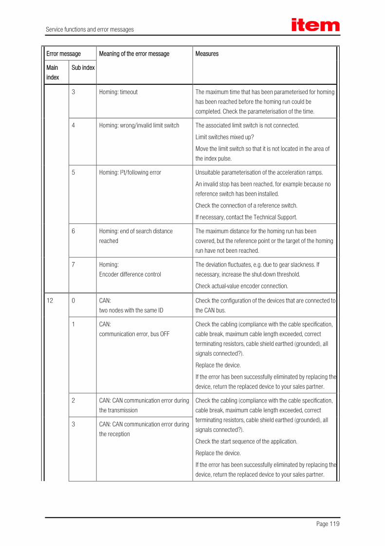
Service functions and error messages
Page 119
Error message Meaning of the error message Measures
Main index
Sub index
3 Homing: timeout The maximum time that has been parameterised for homing has been reached before the homing run could be completed. Check the parameterisation of the time.
4 Homing: wrong/invalid limit switch The associated limit switch is not connected.
Limit switches mixed up?
Move the limit switch so that it is not located in the area of the index pulse.
5 Homing: I²t/following error Unsuitable parameterisation of the acceleration ramps.
An invalid stop has been reached, for example because no reference switch has been installed.
Check the connection of a reference switch.
If necessary, contact the Technical Support.
6 Homing: end of search distance reached
The maximum distance for the homing run has been covered, but the reference point or the target of the homing run have not been reached.
7 Homing: Encoder difference control
The deviation fluctuates, e.g. due to gear slackness. If necessary, increase the shut-down threshold.
Check actual-value encoder connection.
12 0 CAN: two nodes with the same ID
Check the configuration of the devices that are connected to the CAN bus.
1 CAN: communication error, bus OFF
Check the cabling (compliance with the cable specification, cable break, maximum cable length exceeded, correct terminating resistors, cable shield earthed (grounded), all signals connected?).
Replace the device.
If the error has been successfully eliminated by replacing the device, return the replaced device to your sales partner.
2 CAN: CAN communication error during the transmission
Check the cabling (compliance with the cable specification, cable break, maximum cable length exceeded, correct terminating resistors, cable shield earthed (grounded), all signals connected?).
Check the start sequence of the application.
Replace the device.
If the error has been successfully eliminated by replacing the device, return the replaced device to your sales partner.
3 CAN: CAN communication error during the reception

Service functions and error messages
Page 120
Error message Meaning of the error message Measures
Main index
Sub index
4 CAN: node Guarding
Align the cycle time of the remote frames with the PLC or failure of the PLC.
Signals disturbed?
5 CAN: RPDO too short
Check the configuration.
9 CAN: protocol error
Check the command syntax of the control (record the data traffic).
Please contact the Technical Support.
13 0 CAN bus timeout Check the CAN parameterisation.
14 0 Insufficient power supply for the identification
Check the power supply.
Check the motor resistor.
1 Current controller identification: insufficient measurement cycle
The automatic parameter identification process delivers a time constant beyond the value range that can be parameterised. The parameters must be optimised manually.
2 Power output stage could not be enabled
The power output stage has not been enabled. Check the connection of DIN 4.
3 Power output stage prematurely disabled
The power output stage has been disabled during a running identification process (e.g. via DIN 4).
4 Selected resolver type not supported by the identification system
The identification cannot be performed with the present angle encoder settings.
Check the configuration of the angle encoder. If necessary, contact the Technical Support.
5 Index pulse not found The index pulse could not be found after the maximum permissible number of electrical rotations.
Check the index pulse signal.
Check the angle encoder settings.
6 Invalid Hall signals Check the connection.
Check the data sheet as to whether the encoder provides 3 Hall signals with 120° or 60° segments.
If necessary, contact the Technical Support.
7 Identification not possible Check the DC bus circuit voltage.
Check the wiring of the motor/encoder system.
Motor blocked (holding brake not released)?

Service functions and error messages
Page 121
Error message Meaning of the error message Measures
Main index
Sub index
8 Invalid number of pole pairs The calculated number of pole pairs is beyond the parameterisation range. Check the data sheet of the motor.
If necessary, contact the Technical Support.
15 0 Division by 0 Please contact the Technical Support.
1 Out of range error
2 Mathematical underflow
16 0 Incorrect program execution Please contact the Technical Support.
1 Illegal interrupt
2 Initialization error
3 Unexpected state
17 0 Max. following error exceeded Increase the error window.
The parameterisation of the acceleration is too high.
1 Encoder difference monitoring External angle encoder not connected or defective?
The deviation fluctuates, e.g. due to gear slackness. If necessary, increase the shut-down threshold.
2 Current jerk control Please contact the Technical Support.
18 0 Analogue motor temperature warning threshold
Motor too hot? Check the parameterisation (current controller, current limits).
Suitable sensor?
Sensor defective?
Check the parameterisation of the sensor or the characteristic curve of the sensor.
If the error occurs also when the sensor is bypassed, return the device to our sales partner.
21 0 Error 1 current measurement U Please contact the Technical Support.
1 Error 2 current measurement V
2 Error 2 current measurement U
3 Error 1 current measurement V
22 0 PROFIBUS: incorrect initialization
Technology module defective?
Replace the technology module.
If necessary, contact the Technical Support.
1 PROFIBUS: reserved Please contact the Technical Support.

Service functions and error messages
Page 122
Error message Meaning of the error message Measures
Main index
Sub index
2 PROFIBUS: communication error
Check the slave address.
Check the bus terminators.
Check the cabling.
3 PROFIBUS: invalid slave address
Incorrect slave address. Please select another slave address.
4 PROFIBUS: error in value range Mathematical error during the conversion of physical units. The value range of the data and of the physical units do not match (fieldbus display units).
If necessary, contact the Technical Support.
23 0 No consumable record Position save and restore failed, homing required.
1 Record with invalid checksum
2 Flash content inconsistent
25 0 Invalid device type Please return the device to our sales partner.
1 Device type not supported
2 HW revision not supported Check the firmware version.
If necessary, request an update from the Technical Support.
3 Device functionality restricted! Please return the device to our sales partner.
4 Invalid power module type Check the firmware version.
If necessary, request an update from the Technical Support.
5 Incompatibility firmware / hardware. The firmware is not suitable for the device.
Check the firmware version.
If necessary, request an update from the Technical Support.
26 0 No user parameter set Load the default parameter set.
1 Checksum error If the error is still present, return the device to our sales partner.
2 Flash: write error Please return the device to our sales partner.
3 Flash: delete error
4 Flash: error in the internal flash Reload the firmware.
If necessary, contact the Technical Support. 5 No calibration data
6 No user position data set Save and reset.
Load the default parameter set.
If the error occurs again, contact the Technical Support.

Service functions and error messages
Page 123
Error message Meaning of the error message Measures
Main index
Sub index
7 Error in data tables (CAM) Load the default parameter set and perform a start-up procedure.
If necessary, reload the parameter set.
If necessary, contact the Technical Support.
27 0 Following error warning threshold Check the parameterisation of the following error.
Motor blocked?
28 0 No operating hours counter Acknowledge the error.
If the error occurs again, contact the Technical Support. 1 Operating hours counter: write error
2 Operating hours counter corrected
3 Operating hours counter converted
29 0 No SD card Please contact the Technical Support
1 SD card: initialisation error
2 SD card: data error
3 SD card: write error
4 SD card: firmware download error
30 0 Internal conversion error Please contact the Technical Support.
31 0 Motor I²t Motor blocked?
Check the power rating of the drive.
1 Servo positioning controller I²t Check the power rating of the drive package.
2 PFC I²t Check the power rating of the drive.
Select operation without PFC?
3 Braking resistor I²t Braking resistor overloaded.
Use external braking resistor?
4 I²t active power overload Reduce the active power of the drive.
32 0 DC bus circuit charging time exceeded Bridge for the internal brake resistor installed?
Check the connection of the external braking resistor.
If necessary, contact the Technical Support.
1 Undervoltage for active PFC Check whether the power supply complies with the nominal data.
5 Brake chopper overload The DC bus circuit could not be discharged.
Check the ON/OFF cycles.

Service functions and error messages
Page 124
Error message Meaning of the error message Measures
Main index
Sub index
6 DC bus circuit discharge time exceeded Bridge for the internal brake resistor installed?
Check the connection of the external braking resistor.
If necessary, contact the Technical Support.
7 No power supply for the controller enable signal
No DC bus circuit voltage?
Check the power supply.
If necessary, contact the Technical Support.
8 Power supply failure during the controller enabling process
Check the power supply.
9 Phase failure
33 0 Following error, encoder emulation Check the settings of the incremental encoder emulation (number of lines).
If necessary, contact the Technical Support.
34 0 No synchronisation via the field bus Failure of synchronization messages from master?
1 Field bus synchronisation error Failure of synchronization messages from master?
Insufficient synchronisation interval?
35 0 Overspeed protection of the linear motor
The encoder signals are disturbed. Check the installation for compliance with EMC recommendations.
5 Error during the determination of the commutation position
The selected method is not suitable for the motor. Please contact the Technical Support.
36 0 Parameter limited Check the user parameter set.
1 Parameter not accepted
40 0 Negative SW limit switch reached Check the negative range limit.
1 Positive SW limit switch reached Check the positive range limit.
2 Target position beyond the negative SW limit switch
The start of a positioning run has been suppressed, since the target is located beyond the respective software limit switch.
Check the target data.
Check the positioning range. 3 Target position beyond the positive SW
limit switch
41 0 Path program: synchronisation error Check the parameterization.
If necessary, contact the Technical Support.

Service functions and error messages
Page 125
Error message Meaning of the error message Measures
Main index
Sub index
42 0 Positioning: no follow-up position: stop The positioning target cannot be reached with the current positioning options or boundary conditions.
1 Positioning: reversal of rotation not permissible: stop
Check the positioning parameters.
2 Positioning: reversal of rotation not permissible after a stop
3 Positioning start rejected: incorrect operating mode
The change of the mode of operation could not be performed by the position set.
4 Positioning start rejected: homing required
Reset the optional parameterisation “homing required”.
Perform a new homing run.
5 Rotary axis: direction of rotation not permissible
In accordance with the selected mode, the calculated direction of rotation of the rotary axis is not permissible.
Check the selected mode.
9 Error during the start of the positioning run
Check the speed and acceleration parameters.
43 0 Limit switches: negative setpoint blocked
The drive has left the intended motion range.
Technical defect in the system?
Check the limit switches. 1 Limit switches: positive setpoint blocked
2 Limit switches: positioning suppressed
44 0 Error in the cam disc tables Check whether the index has been assigned correctly.
Check whether there are cam discs present in the device.
1 Cam disc: general homing error Ensure that the drive has been homed prior to the activation of the cam disc.
Delete the “homing required” option.
Ensure that a cam disc cannot be started during a homing run.
47 0 Timeout (set-up mode) Check the processing of the request by the PLC.
Speed threshold too low or timeout too small?
48 0 Drive not referenced Switch to positioning and perform a homing run.
50 0 CAN: too many synchronous PDOs
Deactivate the PDOs or increase the SYNC interval. The maximum number of PDOs must not be greater than the factor tp between the position controller and IPO (menu: Parameters/Controller parameters/Cycle times).

Service functions and error messages
Page 126
Error message Meaning of the error message Measures
Main index
Sub index
1 SDO error occurred Please contact the Technical Support.
51 0 No or unknown FSM module or faulty driver supply
Cause: Internal voltage error of the safety module or of the fieldbus activation module.
Action: Module presumably defective. If possible, replace with another module.
Cause: No safety module detected or unknown module type.
Action: Install safety or fieldbus activation module appropriate for the firmware and hardware.
Load firmware appropriate for the safety or fieldbus activation module, see type designation on the module.
2 FSM: different module type Cause: Type or revision of the module does not fit the project planning.
Action: Check whether correct module type and correct version are being used.
With module replacement: Module type not yet configured. Accept currently integrated safety or fieldbus activation module.
3 FSM: different module version Cause: Type or revision of the module is not supported.
Action: Install safety or fieldbus activation module appropriate for the firmware and hardware.
If only a module with a more recent version is available: Load firmware that is appropriate for the module, see type designation on the module.
Cause: The module type is correct but the module version is not supported by the basic device.
Action: Check module version; if possible use module of same version after replacement. Install suitable safety or fieldbus activation module for the firmware and hardware.
If only a module with a more recent version is available: Load firmware that is appropriate for the module, see type designation on the module.
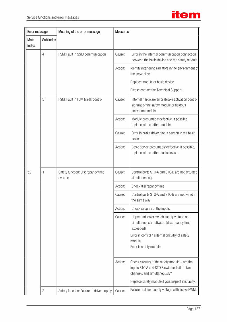
Service functions and error messages
Page 127
Error message Meaning of the error message Measures
Main index
Sub index
4 FSM: Fault in SSIO communication Cause: Error in the internal communication connection between the basic device and the safety module.
Action: Identify interfering radiators in the environment of the servo drive.
Replace module or basic device.
Please contact the Technical Support.
5 FSM: Fault in FSM break control Cause: Internal hardware error (brake activation control signals) of the safety module or fieldbus activation module.
Action: Module presumably defective. If possible, replace with another module.
Cause: Error in brake driver circuit section in the basic device.
Action: Basic device presumably defective. If possible, replace with another basic device.
52 1 Safety function: Discrepancy time overrun
Cause: Control ports STO-A and STO-B are not actuated simultaneously.
Action: Check discrepancy time.
Cause: Control ports STO-A and STO-B are not wired in the same way.
Action: Check circuitry of the inputs.
Cause: Upper and lower switch supply voltage not simultaneously activated (discrepancy time exceeded)
Error in control / external circuitry of safety module. Error in safety module.
Action: Check circuitry of the safety module – are the inputs STO-A and STO-B switched off on two channels and simultaneously?
Replace safety module if you suspect it is faulty.
2 Safety function: Failure of driver supply Cause: Failure of driver supply voltage with active PWM.

Service functions and error messages
Page 128
Error message Meaning of the error message Measures
Main index
Sub index
with active PWM activation Action: The safe status was requested with power output stage enabled. Check integration into the safety-orientated interface.
3 FSM: Rotational speed limits in basic device overlap
Cause: Basic device reports error if the currently requested direction of movement is not possible because the safety module has blocked the setpoint value in this direction.
Error may occur in connection with the SSFx safe speed functions if an asymmetrical speed window is used where one limit is set to zero. In this case, the error occurs when the basic device moves in the blocked direction in the Positioning mode.
Action: Check application and change if necessary.
53 0 USF0: Safety condition violated Cause: Violation of monitored speed limits of the SSF0 in operation / when USF0 / SSF0 requested.
Action: Check when the violation of the safety condition occurs:
a) During dynamic braking to safe rotational speed.
b) After the drive has reached the safe speed.
With a) Check of braking ramp – record measuring data - can the drive follow the ramp?
Change parameters for the slowdown ramp or start time / delay times for monitoring.
With b) Check how far the current speed is from the monitored limit speed; increase distance if necessary (parameter in safety module) or correct speed specified by controller.
1 USF1: Safety condition violated Cause: Violation of monitored speed limits of the SSF1 in operation / when USF1 / SSF1 requested.

Service functions and error messages
Page 129
Error message Meaning of the error message Measures
Main index
Sub index
Action: See USF0, error 53-0.
2 USF2: Safety condition violated Cause: Violation of monitored speed limits of the SSF2 in operation / when USF2 / SSF2 requested.
Action: See USF0, error 53-0.
3 USF3: Safety condition violated Cause: Violation of monitored speed limits of the SSF3 in operation / when USF3 / SSF3 requested.
Action: See USF0, error 53-0.
54 0 SBC: Safety Condition Violated Cause: Brake should engage; no feedback received within the expected time.
Action: Check how the feedback signal is configured – was the correct input selected for the feedback signal?
Does the feedback signal have the correct polarity?
Check whether the feedback signal is actually switching.
Is the parameterised time delay for the analysis of the feedback signal appropriate to the brake used (measure switching time if necessary)?
2 SS2: Safety Condition Violated Cause: Actual speed outside permitted limits for too long.

Service functions and error messages
Page 130
Error message Meaning of the error message Measures
Main index
Sub index
Action: Check when the violation of the safety condition occurs:
c) During dynamic braking to zero. d) After the drive has reached zero speed.
With a) Check of braking ramp – record measuring data - can the drive follow the ramp? Change parameters for the slowdown ramp or start time / delay times for monitoring.
With a) If the option “Trigger basic device quick stop” is activated: Check of the basic device’s quick stop ramp.
With b) Check whether the drive continues to oscillate after reaching the zero speed or remains at idle and stable – increase monitoring tolerance time if necessary.
With b) If the actual speed value is very noisy at rest. Check and if necessary adjust expert parameters for speed recording and detection of idling
3 SOS: Safety Condition Violated Cause: Angle encoder analysis reports “Motor running” (actual speed exceeds limit). Drive has rotated out of its position since reaching the safe state.
Action: Check the position tolerance for the SOS monitoring and increase if necessary, if this is permissible.
If the actual speed value is very noisy when at rest: Check and if necessary adjust expert parameters for speed recording and detection of idling.
4 SS1: Safety Condition Violated Cause: Actual speed is outside of permitted limits for too long.

Service functions and error messages
Page 131
Error message Meaning of the error message Measures
Main index
Sub index
Action: Check when the violation of the safety condition occurs:
e) During dynamic braking to zero. f) After the drive has reached zero speed.
With a) Check of braking ramp – record measuring data - can the drive follow the ramp? Change parameters for the slowdown ramp or start time / delay times for monitoring.
With a) If the option “Trigger basic device quick stop” is activated: Check of the basic device’s quick stop ramp.
With b) Check whether the drive continues to oscillate after reaching the zero speed or remains at idle and stable – increase monitoring tolerance time if necessary.
With b) If the actual speed value is very noisy when at rest: Check and if necessary adjust expert parameters for speed recording and detection of standstill.
5 STO: Safety Condition Violated Cause: Internal hardware error (voltage error) of the safety module.
Action: Module presumably defective. If possible, replace with another module.
Cause: Error in driver circuit section in the basic device.
Action: Basic device presumably defective. If possible, replace with another basic device.
Cause: No feedback received from basic device to indicate that output stage was switched off.

Service functions and error messages
Page 132
Error message Meaning of the error message Measures
Main index
Sub index
Action: Check whether the error can be acknowledged and whether it occurs again upon a new STO request – if yes: Basic device is presumably faulty. If possible, replace with another basic device.
6 SBC: Brake not vented for > 24 hrs Cause: Error occurs when SBC is requested and the brake has not been opened by the basic device in the last 24 hours.
Action: If the brake is actuated via the brake driver in the basic device [X6]: The brake must be energised at least once within 24 hours before the SBC request because the circuit breaker check can only be performed when the brake is switched on (energised).
Only if brake control takes place via DOUT4x and an external brake controller: Deactivate 24 hr monitoring in the SBC parameters if the external brake controller allows this.
7 SOS: SOS requested > 24 hrs Cause: If SOS is requested for more than 24 hours, the error is triggered.
Action: Terminate SOS and move axle at least once during this time.
55 0 No actual rotational speed / position value available or idle > 24 hrs
Cause: Subsequent error when a position encoder fails. Safety function SSF, SS1, SS2 or SOS requested and actual rotational speed value is not valid.
Action: Check the function of the position encoder(s) (see following error).
1 SINCOS encoder [X2B] - Tracking signal error
Cause: Vector length sin²+cos² is outside the permissible range. The amplitude of one of the two signals is outside the permissible range. Offset between analogue and digital signal is greater than 1 quadrant.

Service functions and error messages
Page 133
Error message Meaning of the error message Measures
Main index
Sub index
Action: Error may occur with SIN/COS and Hiperface encoders.
Check the position encoder.
Check the connection wiring (broken wire, short between two signals or signal / screening).
Check the supply voltage for the position encoder.
Check the motor cable / screening on motor and drive side – EMC malfunctions may trigger the error.
2 SINCOS encoder [X2B] - Standstill > 24 hrs
Cause: Input signals of the SinCos encoder have not changed by a minimum amount for 24 hours (when safety function is requested).
Action: Terminate SS2 or SOS and move axle at least once during this time.
3 Resolver [X2A] - Signal error Cause: Vector length sin²+cos² is outside the permissible range. The amplitude of one of the two signals is outside the permissible range. Input signal is static (same values to right and left of maximum).
Action: Check the resolver.
Check the connection wiring (broken wire, short between two signals or signal / screening).
Check for a failure of the primary radiator signal
Check the motor and encoder cable / screening on motor and drive side. EMC malfunctions can trigger the error.
7 Other encoder [X2B] - Faulty angle information
Cause: “Angle faulty” message is sent from basic device when status lasts for longer than the allowed time. Encoder at X2B is analysed by the basic device. Encoder is faulty.
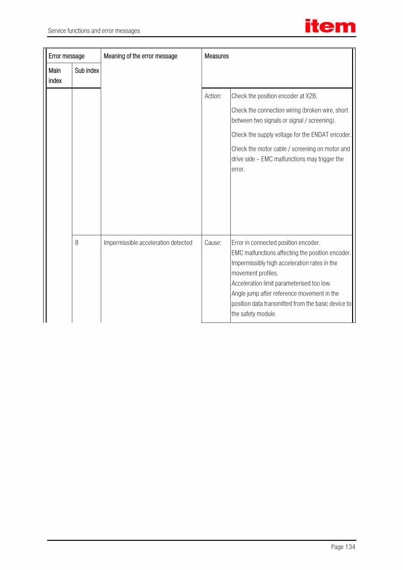
Service functions and error messages
Page 134
Error message Meaning of the error message Measures
Main index
Sub index
Action: Check the position encoder at X2B.
Check the connection wiring (broken wire, short between two signals or signal / screening).
Check the supply voltage for the ENDAT encoder.
Check the motor cable / screening on motor and drive side – EMC malfunctions may trigger the error.
8 Impermissible acceleration detected Cause: Error in connected position encoder. EMC malfunctions affecting the position encoder. Impermissibly high acceleration rates in the movement profiles. Acceleration limit parameterised too low. Angle jump after reference movement in the position data transmitted from the basic device to the safety module.

Service functions and error messages
Page 135
Error message Meaning of the error message Measures
Main index
Sub index
Action: Check the connected position encoder: If further error messages occur in conjunction with the encoders, then eliminate their cause first.
Check the motor and encoder cable / screening on motor and drive side. EMC malfunctions can trigger the error.
Check the setpoint specifications / Movement profiles of the controller: Do they contain impermissibly high temperatures above the limit value for acceleration monitoring (P06.07)?
Check whether the limit value for acceleration monitoring was parameterised correctly - the limit value (P06.07) should be at least 30% ... 50% above the maximum acceleration actually occurring.
In case of an angle jump in the position data transmitted from the basic device - Acknowledge error once.
56 8 Rotational speed / angle difference, encoder 1 - 2
Cause: Rotational speed difference between encoder 1 and 2 of one µC outside the permissible range for longer than the allowed time. Angle difference between encoder 1 and 2 of one µC outside the permissible range for longer than the allowed time.
Action: Problem may occur if two position encoders are used in the system and they are not “rigidly coupled”.
Check for elasticity or looseness, improve mechanical system.
Adjust the expert parameters for the position comparison if this is acceptable from an application point of view.

Service functions and error messages
Page 136
Error message Meaning of the error message Measures
Main index
Sub index
9 Error, cross-comparison of encoder analysis
Cause: Cross-comparison between µC1 and µC2 has detected an angle difference or rotational speed difference or difference in capture times for the position encoders.
Action: Timing disrupted. If the error occurs again after a reset, the safety module is presumably faulty.
57 0 Error, I/O self test (internal/external) Cause: Internal error of digital inputs DIN40 ... DIN43 (detected via internal test signals). Error at brake output at X6 (signalling, detected by test pulses). Internal error of brake output (detected via internal test signals). Internal error of digital outputs DOUT40 – DOUT42 (detected via internal test signals).

Service functions and error messages
Page 137
Error message Meaning of the error message Measures
Main index
Sub index
Action: Check the connection wiring for the digital outputs DOUT40 ... DOUT42 (short circuit, cross circuit, etc.).
Check the connection wiring for the brake (short circuit, cross circuit, etc.).
Brake connection: The error may occur with long motor cables if:
1. The brake output X6 was configured for the brake (this is the case with factory settings!) and
2. A motor without a holding brake is used and the brake connection lines in the motor cable are terminated at X6. In this case: Disconnect the brake connection lines at X6.
If there is no error in the connection wiring, there may be an internal error in the module (check by swapping the module).
1 Digital inputs - Signal level error Cause: Exceeding / violation of discrepancy time with multi-channel inputs (DIN40 ... DIN43, two-handed control device, mode selector switch).

Service functions and error messages
Page 138
Error message Meaning of the error message Measures
Main index
Sub index
Action: Check the external active and passive sensors – do they switch on two channels and simultaneously (within the parameterised discrepancy time).
Two-handed control device: Check how the device is operated by the user – are both pushbuttons pressed within the discrepancy time? Give training if necessary.
Check the set discrepancy times – are they sufficient?
2 Digital inputs - Test pulse error Cause: One or more inputs (DIN40 ... DIN49) were configured for the analysis of the test pulses of the outputs (DOUT40 ... DOUT42). The test pulses from DOUTx do not arrive at DIN4x.
Action: Check the wiring (shorts after 0 V, 24 V, cross circuits).
Check the assignment – correct output selected / configured for test pulse?
6 Electronics temperature too high Cause: The safety module's temperature monitor has been triggered; the temperature of µC1 or µC2 was below -20° or above +75°C.
Action: Check the operating conditions (ambient temperature, control cabinet temperature, installation situation in the control cabinet).
If the servo drive is experiencing high thermal load (high control cabinet temperature, high power consumption / output to motor, large number of occupied slots), a servo drive of the next higher output level should be used.
58 0 FSM: Plausibility check of parameters Cause: The plausibility check in the safety module produced errors, e.g. an invalid angle encoder configuration; the error is triggered when a validation code is requested by the SafetyTool and when parameters are backed up in the safety module.
Action: Note instructions for SafetyTool for complete validation; check parameterisation.
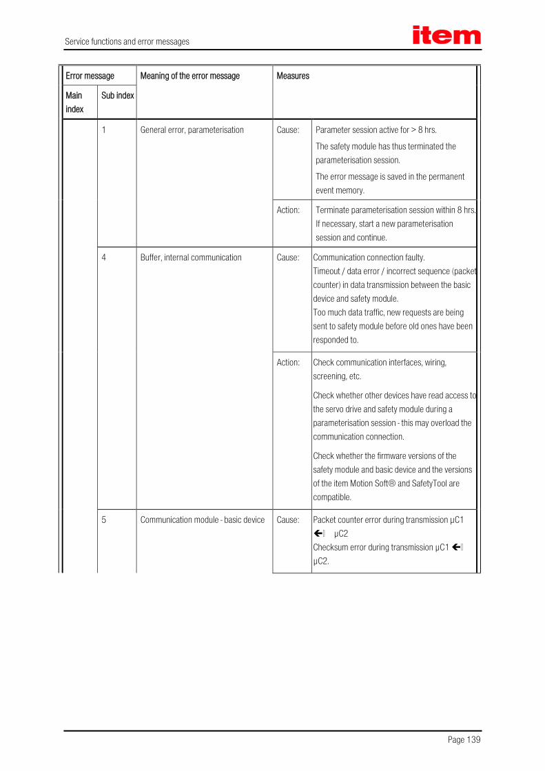
Service functions and error messages
Page 139
Error message Meaning of the error message Measures
Main index
Sub index
1 General error, parameterisation Cause: Parameter session active for > 8 hrs.
The safety module has thus terminated the parameterisation session.
The error message is saved in the permanent event memory.
Action: Terminate parameterisation session within 8 hrs. If necessary, start a new parameterisation session and continue.
4 Buffer, internal communication Cause: Communication connection faulty. Timeout / data error / incorrect sequence (packet counter) in data transmission between the basic device and safety module. Too much data traffic, new requests are being sent to safety module before old ones have been responded to.
Action: Check communication interfaces, wiring, screening, etc.
Check whether other devices have read access to the servo drive and safety module during a parameterisation session - this may overload the communication connection.
Check whether the firmware versions of the safety module and basic device and the versions of the item Motion Soft® and SafetyTool are compatible.
5 Communication module - basic device Cause: Packet counter error during transmission µC1 µC2 Checksum error during transmission µC1 µC2.

Service functions and error messages
Page 140
Error message Meaning of the error message Measures
Main index
Sub index
Action: Internal malfunction in the servo drive.
Check whether the firmware versions of the safety module and basic device and the versions of the item Motion Soft® and SafetyTool are compatible.
6 Error in cross-comparison for processors 1 - 2
Cause: Timeout during cross-comparison (no data) or cross-comparison faulty (data for µC1 and µC2 are different).
Error in cross-comparison for digital I/O. Error in cross-comparison for analogue input. Error in cross-comparison for internal operating voltage measurement (5 V, 3.3 V, 24 V) and reference voltage (2.5 V). Error in cross-comparison for SIN/COS angle encoder analogue values. Error in cross-comparison for programme sequence monitoring. Error in cross-comparison for interrupt counter. Error in cross-comparison for input map. Error in cross-comparison for violation of safety conditions. Error in cross-comparison for temperature measurement.
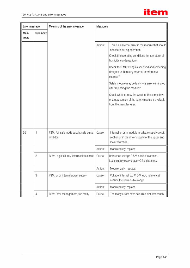
Service functions and error messages
Page 141
Error message Meaning of the error message Measures
Main index
Sub index
Action: This is an internal error in the module that should not occur during operation.
Check the operating conditions (temperature, air humidity, condensation).
Check the EMC wiring as specified and screening design; are there any external interference sources?
Safety module may be faulty – is error eliminated after replacing the module?
Check whether new firmware for the servo drive or a new version of the safety module is available from the manufacturer.
59 1 FSM: Fail-safe mode supply/safe pulse inhibitor
Cause: Internal error in module in failsafe supply circuit section or in the driver supply for the upper and lower switches.
Action: Module faulty, replace.
2 FSM: Logic failure / intermediate circuit Cause: Reference voltage 2.5 V outside tolerance. Logic supply overvoltage +24 V detected.
Action: Module faulty, replace.
3 FSM: Error internal power supply Cause: Voltage (internal 3.3 V, 5 V, ADU reference) outside the permissible range.
Action: Module faulty, replace.
4 FSM: Error management, too many Cause: Too many errors have occurred simultaneously.

Service functions and error messages
Page 142
Error message Meaning of the error message Measures
Main index
Sub index
errors Action: Clarify: What is the status of the installed safety module - does it contain a valid parameter set?
Read out and analyse the permanent event memory of the basic device via item Motion Soft®
Eliminate error causes step by step.
Install safety module with “delivery status” and perform commissioning of basic device.
If this is not available: Set factory settings in the safety module, then copy data from the basic device and perform complete validation. Check whether the error occurs again.
5 FSM: Log file - write error Please contact the Technical Support.
6 FSM: Parameter set - save error
Please contact the Technical Support.
7 FSM: Flash checksum error Cause: Voltage interruption / power off while parameters were being saved. Flash memory in safety module corrupted (e.g. by extreme malfunctions).
Action: Check whether the error recurs after a reset. If it does:
Parameterise the module again and validate the parameter set again. If error persists:
Module faulty, replace.
8 FSM: Internal monitoring, processor 1 - 2
Cause: Serious internal error in the safety module: Error detected while dynamising internal signals. Disrupted programme sequence, stack error or OP code test failed, processor exception / interrupt.
Action: Check whether the error recurs after a reset. If it does:
Module faulty, replace.
9 FSM: Structure error, invalid software state
Cause: Triggering of internal programme sequence monitoring.
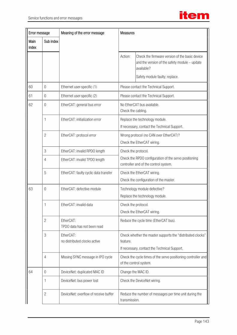
Service functions and error messages
Page 143
Error message Meaning of the error message Measures
Main index
Sub index
Action: Check the firmware version of the basic device and the version of the safety module – update available?
Safety module faulty; replace.
60 0 Ethernet user-specific (1) Please contact the Technical Support.
61 0 Ethernet user-specific (2) Please contact the Technical Support.
62 0 EtherCAT: general bus error No EtherCAT bus available. Check the cabling.
1 EtherCAT: initialization error Replace the technology module.
If necessary, contact the Technical Support.
2 EtherCAT: protocol error Wrong protocol (no CAN over EtherCAT)?
Check the EtherCAT wiring.
3 EtherCAT: invalid RPDO length Check the protocol.
Check the RPDO configuration of the servo positioning controller and of the control system.
4 EtherCAT: invalid TPDO length
5 EtherCAT: faulty cyclic data transfer Check the EtherCAT wiring.
Check the configuration of the master.
63 0 EtherCAT: defective module Technology module defective?
Replace the technology module.
1 EtherCAT: invalid data Check the protocol.
Check the EtherCAT wiring.
2 EtherCAT: TPDO data has not been read
Reduce the cycle time (EtherCAT bus).
3 EtherCAT: no distributed clocks active
Check whether the master supports the “distributed clocks” feature.
If necessary, contact the Technical Support.
4 Missing SYNC message in IPO cycle Check the cycle times of the servo positioning controller and of the control system.
64 0 DeviceNet: duplicated MAC ID Change the MAC ID.
1 DeviceNet: bus power lost Check the DeviceNet wiring.
2 DeviceNet: overflow of receive buffer Reduce the number of messages per time unit during the transmission.

Service functions and error messages
Page 144
Error message Meaning of the error message Measures
Main index
Sub index
3 DeviceNet: overflow of transmit buffer Reduce the number of message per time unit that are to be transmitted.
4 DeviceNet: IO send error Please contact the Technical Support.
5 DeviceNet: bus Off Check the DeviceNet wiring.
6 DeviceNet: CAN controller overflow
Please contact the Technical Support.
65 0 DeviceNet: no module Technology module defective?
Replace the technology module.
1 DeviceNet: I/O connection timeout Please contact the Technical Support.
72 0 Profinet: Initialization error Replace the Profinet module.
1 Profinet: Bus error No communication possible, e.g. because the
bus cable is disconnected. Check the cabling and restart the Profinet communication.
3 Profinet: Invalid IP configuration IP address, subnet mask or gateway address are not valid or not permissible.
Change IP configuration.
4 Profinet: Invalid device name According to the Profinet standard, the Profinet device name is not permissible.
Change device name.
5 Profinet: Technology module defect Replace the Profinet module.
6 Profinet: Invalid / not supported indication
A Profinet feature has been used that is not supported by the module.
If necessary, contact the Technical Support.
78 0 NRT frame send error Reduce bus traffic, for example by using less devices in a line.
80 0 IRQ: current controller overflow
Please contact the Technical Support.

Service functions and error messages
Page 145
Error message Meaning of the error message Measures
Main index
Sub index
1 IRQ: speed controller overflow
2 IRQ: position controller overflow
3 IRQ: interpolator overflow
81 4 IRQ: low-level overflow
Please contact the Technical Support.
5 IRQ: MDC overflow
82 0 Sequence control: general For information only, no measures required.
1 CO write access started multiple times Please contact the Technical Support.
83 0 Invalid technology module or Technology module: (slot/combination)
Load the correct firmware. Check the slot.
If necessary, contact the Technical Support.
1 Technology module not supported Load the correct firmware.
If necessary, contact the Technical Support. 2 Technology module: HW revision not supported
3 Service memory module: write error Please contact the Technical Support.
84 0 State change of the sequence control Detailed information concerning internal processes.
No measures required. If necessary, select the option “Entry into buffer” in the error management.
90 0 Missing hardware component (SRAM) Please contact the Technical Support.
1 Missing hardware component (FLASH)
2 Error during booting of FPGA
3 Error during start of SD-ADUs
4 SD-ADU synchronisation error after start
5 SD-ADU not synchronous

Service functions and error messages
Page 146
Error message Meaning of the error message Measures
Main index
Sub index
6 IRQ 0 (current controller): trigger error
7 CAN controller not available
8 Device parameters checksum error
9 DEBUG-Firmware loaded
91 0 Internal initialisation error Please contact the Technical Support.
1 Memory error
2 Controller/power stage code read error
3 Internal software initialization error
92 0 Error during firmware download Incorrect firmware? Load the correct firmware.
If necessary, contact the Technical Support.
1 Error during Bootloader Update Please contact the Technical Support.

Technology modules
Page 147
12 Technology modules
12.1 PROFIBUS-DP interface
12.1.1 Product description
The PROFIBUS-DP interface provides an additional field bus connection. All functions and parameters can be addressed directly, for example from a Simatic S7 control system. The interface is plugged into the technology slot TECH 2 of the item servo positioning controller C Series.
The PROFIBUS-DP interface is supported solely in the TECH 2 technology slot.
Additional technology modules will not be supported if the PROFIBUS-DP interface is used.
If your specific requirements are more complex, please contact your sales partner in order to find a solution for your particular application.
As a special feature, S7 function blocks have been developed for the servo positioning controllers. Using these function blocks, the servo positioning controllers can be controlled directly by the PLC program and the users can integrate their systems easily and clearly into the Simatic S7 environment.
12.1.2 Technical data
Table 45: Technical data: PROFIBUS-DP interface: Ambient conditions, dimensions and weight
Range Values
Storage temperature range -25 °C to +75°C
Operating temperature range / deratings 0°C to 50°C
Atmospheric humidity 0..90%, non-condensing
Altitude Up to 2000 m above msl
External dimensions (LxWxH): approx. 92 x 65 x 19mm suitable for the technology slot TECH 2
Weight: approx. 50g
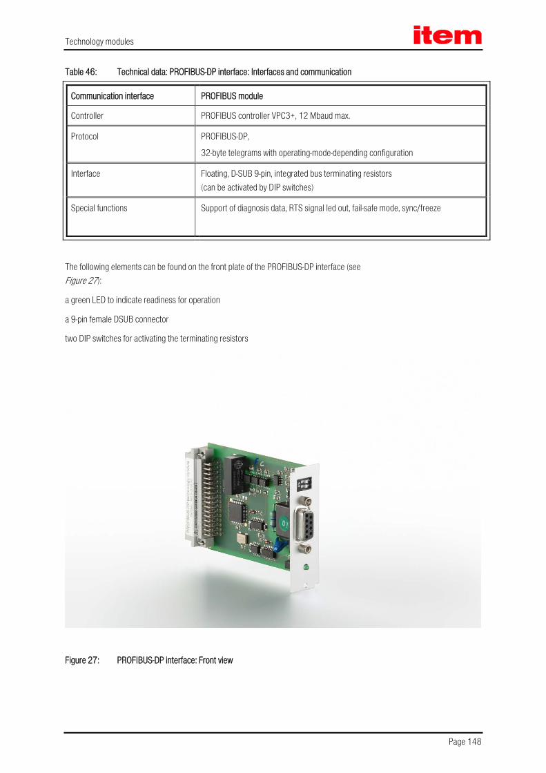
Technology modules
Page 148
Table 46: Technical data: PROFIBUS-DP interface: Interfaces and communication
Communication interface PROFIBUS module
Controller PROFIBUS controller VPC3+, 12 Mbaud max.
Protocol PROFIBUS-DP,
32-byte telegrams with operating-mode-depending configuration
Interface Floating, D-SUB 9-pin, integrated bus terminating resistors (can be activated by DIP switches)
Special functions Support of diagnosis data, RTS signal led out, fail-safe mode, sync/freeze
The following elements can be found on the front plate of the PROFIBUS-DP interface (see Figure 27):
a green LED to indicate readiness for operation
a 9-pin female DSUB connector
two DIP switches for activating the terminating resistors
Figure 27: PROFIBUS-DP interface: Front view
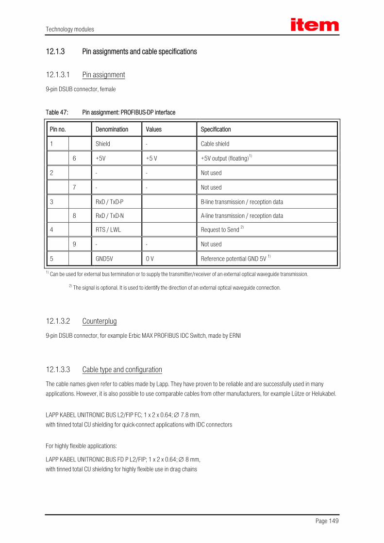
Technology modules
Page 149
12.1.3 Pin assignments and cable specifications
12.1.3.1 Pin assignment
9-pin DSUB connector, female
Table 47: Pin assignment: PROFIBUS-DP interface
Pin no. Denomination Values Specification
1 Shield - Cable shield
6 +5V +5 V +5V output (floating)1)
2 - - Not used
7 - - Not used
3 RxD / TxD-P B-line transmission / reception data
8 RxD / TxD-N A-line transmission / reception data
4 RTS / LWL Request to Send 2)
9 - - Not used
5 GND5V 0 V Reference potential GND 5V 1)
1) Can be used for external bus termination or to supply the transmitter/receiver of an external optical waveguide transmission.
2) The signal is optional. It is used to identify the direction of an external optical waveguide connection.
12.1.3.2 Counterplug
9-pin DSUB connector, for example Erbic MAX PROFIBUS IDC Switch, made by ERNI
12.1.3.3 Cable type and configuration
The cable names given refer to cables made by Lapp. They have proven to be reliable and are successfully used in many applications. However, it is also possible to use comparable cables from other manufacturers, for example Lütze or Helukabel.
LAPP KABEL UNITRONIC BUS L2/FIP FC; 1 x 2 x 0.64; ∅ 7.8 mm, with tinned total CU shielding for quick-connect applications with IDC connectors
For highly flexible applications:
LAPP KABEL UNITRONIC BUS FD P L2/FIP; 1 x 2 x 0.64; ∅ 8 mm, with tinned total CU shielding for highly flexible use in drag chains

Technology modules
Page 150
12.1.4 Termination and bus terminating resistors
Every bus segment of a PROFIBUS network has to be equipped with bus terminating resistors to minimise line reflections and to adjust a defined rest potential on the line. The bus termination has to be provided at the beginning and at the end of every bus segment.
Most PROFIBUS connectors come supplied with integrated terminating resistors. For bus connections with connectors without integrated terminating resistors, the PROFIBUS-DP interface has its own terminating resistors. They can be activated with the help of the two DIP switches on the module (switch set to ON).
To ensure safe operation of the network, only one bus termination may be used at a time.
The external connection can also be set up discretely (see Figure 28). The power supply of 5 V required for the externally connected terminating resistors is supplied at the PROFIBUS connector of the PROFIBUS-DP interface (see pin assignment in Table 47).
GND 5 V
+5 V
A-LineB-Line
390 Ohm
220 Ohm
390 Ohm
Figure 28: PROFIBUS-DP interface: Connection with external terminating resistors

Technology modules
Page 151
12.2 EtherCAT
12.2.1 Product description
The EtherCAT technology module enables the connection of the item servo positioning controller C Series to the EtherCAT fieldbus system. The communication via the EtherCAT interface (IEEE-802.3u) is realised with the aid of standard EtherCAT cabling.
In the case of the item servo positioning controller C Series supports the CoE protocol (CANopen over EtherCAT) with the FPGA ESC20 made by Beckhoff.
The EtherCAT technology module is supported solely in the TECH 2 technology slot.
Additional technology modules will not be supported if the EtherCAT technology module is used.
If your specific requirements are more complex, please contact your sales partner in order to find a solution for your particular application.
12.2.2 Characteristics of the EtherCAT technology module
The EtherCAT technology module has the following characteristics:
It can be fully mechanically integrated in the item servo positioning controller C Series
EtherCAT corresponding to IEEE-802.3u (100Base-TX) with 100 Mbps (full duplex)
Star and line topology
Connector: RJ45
Electrically isolated EtherCAT interface
Communication cycle: 1ms
127 slaves max.
EtherCAT slave implementation based on FPGA ESC20 by Beckhoff
Support of the “Distributed Clocks” feature for synchronised set value transfer
LED display for indicating readiness and link-detect

Technology modules
Page 152
Figure 29: EtherCAT module: Front view
12.2.3 Technical data
Table 48: Technical data: EhterCAT module: Ambient conditions, dimensions and weight
Range Values
Storage temperature range -25°C to +75°C
Operating temperature range 0°C to 50°C
Atmospheric humidity 0..90%, non-condensing
Altitude up to 2000 m above msl
External dimensions (LxWxH): approx. 92 x 65 x 19 mm
Weight: approx. 55 g
Slot Technology slot TECH 2
12.2.4 Display elements
The front panel of the EtheCAT technology module is equipped with two LEDs for indicating the operating states.
Table 49: Display elements

Technology modules
Page 153
Element Function
LED 1
Two-colour-LED (green/red)
Run (green), link/activity EtherCAT port 1 (red),
EtherCAT active (yellow)
LED 2 (red) Link/activity EtherCAT port 2
12.2.5 EtherCAT interface
Table 50: Signal level and differential voltage
Signal level 0 ... 2.5 VDC
Differential voltage 1.9 ... 2.1 VDC

Technology modules
Page 154
12.3 General installation notes for technology modules
DANGER!
Non-observance of the instructions that are stated in chapter 2 Safety notes for electrical drives and controllers (page 16) may lead to property damage, injuries, electric shock, or – in extreme cases – even death.
DANGER!
Prior to installing technology modules, the servo positioning controller has to be disconnected from any current-carrying conductors. After the operating voltage has been disconnected, wait for 5 minutes so that the capacities in the servo positioning controller can be completely discharged.
Caution!
Make sure that ESD protection measures are taken when handling technology modules.
To insert a technology module into the item servo positioning controller C 1-Series, please proceed as follows:
Remove the front plate of the technology slot (TECH 1 or TECH 2) of the servo positioning controller with a suitable Phillips screwdriver.
Push the technology module into the open technology slot so that the lateral guides hold the board.
Push the technology module into the slot until it reaches the stop.
Screw the technology module onto the front side of the housing of the servo positioning controller with the Phillips screw.
Ensure that the front plate of the technology module has conducting contact with the housing of the servo positioning controller (PE).
Figure 30: Servo positioning controller with integrated technology module


![MDR0998Rp0012 S A02 171114 F01 Environmental R… · [SouthernRegion] [MDR0998Rp0012_F01] 78 5.2.7 CulturalHeritage The main issue for archaeological, architectural and cultural heritage](https://static.fdocuments.net/doc/165x107/5fc9d7360487c725ec11fb8a/mdr0998rp0012-s-a02-171114-environmental-r-southernregion-mdr0998rp0012f01.jpg)


