DESIGN VERIFICATION ON BORED PILE WITHIN KENNY HILL ...
21
DESIGN VERIFICATION ON BORED PILE WITHIN KENNY HILL FORMATION VIA STATIC LOAD TEST ZALINA BINTI MOHAMED A thesis submitted in partial fulfilment of the requirements for the award of the degree of Master of Engineering (Civil-Geotechnics) Faculty of Civil Engineering Universiti Teknologi Malaysia JUNE 2010
Transcript of DESIGN VERIFICATION ON BORED PILE WITHIN KENNY HILL ...

DESIGN VERIFICATION ON BORED PILE WITHIN KENNY HILL FORMATION
VIA STATIC LOAD TEST
ZALINA BINTI MOHAMED
A thesis submitted in partial fulfilment of the
requirements for the award of the degree of
Master of Engineering (Civil-Geotechnics)
Faculty of Civil Engineering
Universiti Teknologi Malaysia
JUNE 2010

iii
For my beloved family members
And all my friends
You’re my everything for me

iv
AKNOWLEDGEMENT
I would like to phrase my heartfelt to my project supervisor, Prof. Dr. Khairul
Anuar Kassim for guidance and supports that had been given throughout of the
duration of this project.
Besides, I wish to express my sincere appreciation to all MegaConsult Sdn.
Bhd staffs especially Ir. Mohd Taha Abd. Wahab, Ir. Razali Ahmad, Ir. Farhan and
Nurulhusna Mohd Hussin for encouragement guidance, critics during preparing this
thesis.
Last but not least, I would like to thanks to my beloved parents, brother and
sisters, friends especially Dzul Azmi Abu Samah, Norshida Mhd. Ali Osman, Siti
Norazela Hassan and Azhani Zukri for their support throughout my studies.

v
ABSTRACT
Due to variation in soil layers, it is not easy for engineer to be assured that
theoretical design of piles comply with the actual site condition. Thus, every design
of piled foundations carries its own uncertainty and risk. This study evaluates the
applicability of six methods to predict the ultimate bearing capacity of bored pile by
static load test at site. Analyses and evaluation were conducted on six bored piles of
different sizes and length. The methods are Chin-Kondner’s Method, Brinch
Hansen’s Method, DeBeer’s Method, Butler & Hoy’s Method, Fuller & Hoy’s and
Decourt’s Method. The pile capacities determined using the different methods were
compared with the theoretical method such as semi-empirical method and simplified
soil mechanic method within Kenny Hill formation. Results of the analyses show that
the best performing method is DeBeer’s Method. Fuller & Hoys’s and Butler &
Hoy’s methods is the recommended method for bored pile design practice as it is
consistent in predicting the bored pile capability. Chin-Kondner’s method is the over
predicted most than the others interpretation methods.

vi
ABSTRAK
Berikutan terdapat perbezaan lapisan tanah, adalah rumit bagi seseorang
jurutera untuk memastikan rekaan cerucuk secara teorinya adalah sama dengan
keadaan di tapak. Oleh itu, setiap rekaan asas cerucuk mempunyai ketidakpastian dan
risiko yang tersendiri. Kajian ini dijalankan bagi menilai kesesuaian enam jenis
kaedah untuk menentukan keupayaan muktamad cerucuk gerek melalui ujian beban
static di tapak. Analisis dan penilaian telah dijalankan ke atas enam cerucuk gerek
yang berlainan saiz dan panjang. Kaedah-kaedah yang digunakan adalah Chin-
Kondner’s Method, Brinch Hansen’s Method, DeBeer’s Method, Butler & Hoy’s
Method, Fuller & Hoy’s and Decourt’s Method. Nilai yang telah ditentukan oleh
kaedah-kaedah yang dinyatakan telah dibuat perbandingan dengan beban maksimum
yang telah diukur oleh kaedah teori seperti kaedah separa empirical dan juga
mekanik tanah terubahsuai di dalam formasi Kenny Hill. Keputusan daripada analisis
menunjukkan kaedah DeBeer’s merupakan kaedah terbaik berbanding dengan
kaedah yang lain. Kaedah Fuller & Hoy’s dan kaedah Butler & Hoy merupakan
kaedah yang dicadangkan bagi rekabentuk cerucuk gerek ia agak kerana konsistan di
dalam meramalkan keupayaan cerucuk gerek. Kaedah Chin-Kondner pula
merupakan kaedah yang member nilai tertinggi berbanding kaedah-kaedah yang lain.

vii
TABLE OF CONTENTS
CHAPTER TITLE
PAGE
TITLE PAGE
DECLARATION
DEDICATION
ACKNOWLEDGEMENTS
ABSTRACT
ABSTRAK
TABLE OF CONTENTS
LIST OF TABLES
LIST OF FIGURES
LIST OF SYMBOLS
LIST OF APENDICES
i
ii
iii
iv
v
vi
vii
xi
xii
xiii
xv
1 INTRODUCTION
1.1 Background
1.2 Important of Study
1.3 Objectives of the Study
1.4 Scope and Limitation of the Study
1
3
3
4

viii
2 LITERATURE REVIEW
PAGE
2.1
Bored Pile
2.1.1 Types of Bored Piles
2.1.2 Construction Procedures
2.1.2.1 Dry Method
2.1.2.2 Casing Method
2.1.2.3 Wet Method
2.1.3 Techniques and Equipment
2.1.3.1 Power Augers
2.1.3.2 Boring with Casing Oscillators
2.1.3.3 Continuous Flight Auger Drilling Rigs
2.1.3.4 Drilling with Kelly
2.1.3.5 Reverse-Circulation Drilling Rigs
2.1.3.6 Tripod Rigs
5
6
6
6
7
7
8
8
8
9
9
9
10
11
11
12
12
14
17
23
23
24
24
25
26
26
27
28
29
29
30
2.2 Geotechnical Capacity of Bored Pile
2.2.1 Factor of Safety
2.2.2 Design of Geotechnical Capacity in Soil
2.2.2.1 Semi-empirical Method
2.2.2.2 Simplified Soil Mechanics Method
2.2.3 Design of Geotechnical Capacity in Rock
2.2.4 Advantage of Bored Test
2.2.5 Disadvantage of Bored Test
2.3
2.4
Pile Load Testing
2.3.1 Static Pile Load Test
2.3.1.1 Test Procedures
Interpretation of the Results from Static Load Test
2.4.1 Chin-Kondner’s Method
2.4.2 Brinch Hansen’s Method
2.4.3 DeBeer’s Method
2.4.4 Butler & Hoy’s Method
2.4.5 Fuller & Hoy’s Method
2.4.6 Decourt’s Exploration Method

ix
2.5
Kenny Hill Formation
PAGE
31
3
METHODOLOGY
3.1 Introduction
3.2 Data Collection
3.3 Complication of Data
3.3.1 Soil Data
3.3.2 Standard Penetration Test (SPT)
3.3.3 Pile Load Test Report
3.4 Data Analysis
3.5 Comparison of the Results
3.6 Conclusion and Recommendation
32
32
33
34
34
34
35
35
36
4 CASE STUDY
4.1 Location of Study
4.2 Analysis of Field Data
4.3 Static Pile Load Test
4.3.1 Method of Loading
37
39
41
41
5 ANALISYS AND RESULTS
5.1 Introduction
5.2 Result from Theoretical Method
5.3 Analysis of Static Load Test
5.4 Theoretical Method versus Interpretation Method
42
42
44
45
6
CONCLUSIONS AND RECOMMENDATIONS
6.1 Conclusions
6.2 Recommendations
49
50

x
REFERENCES
PAGE
51
APPENDIX 53

xi
LIST OF TABLES
TABLE NO. TITLE PAGE
Table 4.1 Relationship between SPT, N Value and Weathering
Grade
39
Table 4.2
Table 4.3
Subsoil Classification (Kamoo and Morgana, 1988)
Pile Details
40
41
Table 5.1
Table 5.2
Pile Capacities from Semi-empirical Method
Pile Capacities from Simplified Soil Mechanic
Method
43
43
Table 5.3
Table 5.4
Pile Capacity for Static Load Test using Various
Method
Summary of Bored Pile Investigated
44
48
xii
LIST OF FIGURES
FIGURE NO. TITLE PAGE
Figure 2.1 Rock Socket reduction Factor, 19
Figure 2.2 Rock Socket reduction Factor, 20
Figure 2.3 Modulus ratio Ranges 21
Figure 2.4 Relation between Socket Roughness, Socket
Reduction Factor Normalized Rock Strength
22
Figure 2.5 Chin-Kondner Method
26
Figure 2.6 Brinch Hansen Method 27
Figure 2.7 DeBeer Method 28
Figure 2.8 Fuller & Hoy and Butler & Hoy Method
29
Figure 2.9
Figure 3.1
Figure 4.1
Figure 5.1
Figure 5.2
Figure 5.3
Figure 5.4
Figure 5.5
Decourt Method
Flow Chart of the Study
Location Plan of Site 1 at Jalan Duta
Results for Pile KDN 7/I
Results for Pile KDN 4C/1
Results for Pile KDN 14/G
Results for Pile UM G/6
Results for Pile UM B/5
30
33
38
45
46
46
47
47
xiii
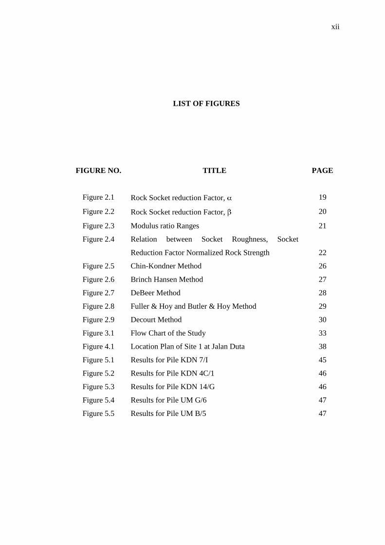
LIST OF SYMBOLS
- Geotechnical capacity (have not included down-drag force, if any)
- Ultimate shaft capacity
i - Number of soil layers
- Ultimate base capacity
- Unit shaft resistance for each layer of embedded soil
- Unit base resistance for the bearing layer of soil
- Pile shaft area
- Pile base area
- Global Factor of Safety for Total Resistance
- Ultimate shaft resistance factor
- Ultimate base resistance factor
SPT’N - Standard Penetration Tests blow counts (blows/300mm)
- Adhesion factor
- Undrained shear strength (kPa)
- Effective Stress Shaft Resistance Factor
- Vertical Effective Stress (kPa)
- Effective Angle of Friction (degree) of fined grained soils
- Bearing capacity factor
- Shaft resistance factor for coarse grained soils
- Unconfined compressive strength of intact rock
- Indicator of rocket roughness
- Atmospheric pressure for normalization

xiv
-
-
-
xv
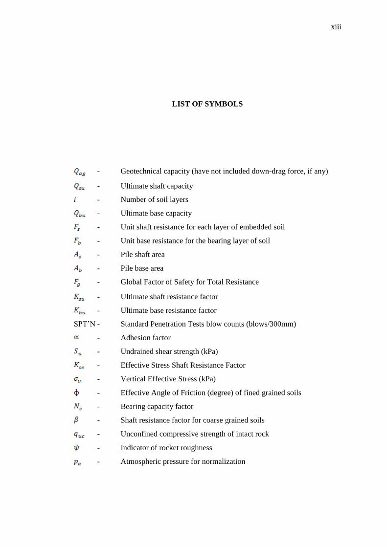
LIST OF APPENDICES
APPENDIX NO. TITLE PAGE
Appendix A1 Bearing Capacity of Pile KDN 7/1 from Semi-
Empirical Method
53
Appendix A2 Bearing Capacity of Pile KDN 7/1 from Simplified
Soil Mechanic
54
Appendix A3 Bearing Capacity of Pile KDN 7/1 from Load test
Interpretation Method
55
Appendix B1 Bearing Capacity of Pile KDN 4/C1 from Semi-
Empirical Method
58
Appendix B2 Bearing Capacity of Pile KDN 4/C1 from Soil
Simplified Method
59
Appendix B3 Bearing Capacity of Pile KDN 4/C1 from Load test
Interpretation Method
60
Appendix C1 Bearing Capacity of Pile KDN 14/G from Semi-
Empirical Method
63
Appendix C2 Bearing Capacity of Pile KDN 14/G from Soil
Simplified Method
64
Appendix C3 Bearing Capacity of Pile KDN 14/G from Load test
Interpretation Method
65
Appendix D1 Bearing Capacity of Pile UM G6 from Semi-Empirical
Method
68

xvi
Appendix D2 Bearing Capacity of Pile UM G6 from Soil Simplified
Method
69
Appendix D3 Bearing Capacity of Pile UM G6 from Load Test
Interpretation Method
70
Appendix E1 Bearing Capacity of Pile UM B5 from Semi-Empirical
Method
73
Appendix E2 Bearing Capacity of Pile UM B5 from Soil Simplified
Method
74
Appendix E3 Bearing Capacity of Pile UM B5 from Load Test
Interpretation Method
75

1
CHAPTER 1
INRODUCTION
1.1 Background
Pile foundations are the part of a heavy structure used to carry and transfer its
load to the bearing ground located at some depth below ground surface. Depending
upon various factors like nature of substrata, depth of ground water table, depth of
stronger stratum, type and quantum of load to be supported etc., piles are designed.
Pile testing is considered a fundamental part of pile foundation design. It is one of
the most effective means of dealing with uncertainties that inevitably arise during the
design and construction of piles.
There is much different type of pile in use today, such as timber piles,
concrete piles, steel piles, composite piles and others. The choice of pile type for a
particular job depends upon the combination of all various soil conditions and the
magnitude of the applied load; for example precast concrete piles (spun pile) are
usually used in water structure such as jetty and breakwater.

2
Current practice of pile design is based on the static analysis for example
Mayerholf Method, Vesic Method and Coyle & Castello methods. Due to the
uncertainties associated the pile design, field tests (pile load test) are usually
conducted to verify the designs load and to evaluate the actual response of the pile
under loading. Static pile load test are verification tool for pile design and they
cannot be a substitute for the engineering analysis of the pile behaviours.
Results of these pile load tests have been compared with the load carrying
capacity of the pile computed by empirical relations proposed by different
researchers. In addition six (6) different methods to interpret ultimate load from load
/ settlement relationship have been used with the purpose to select the method most
suitable for existing conditions.
Pile foundations are part of a heavy structure used to carry and transfer load
to the bearing ground located at some depth below ground surface. Pile are design
depending upon various factors like nature of substrata, depth of ground water table,
depth of stronger stratum, type and quantum of load to be supported etc. Pile testing
is considered a fundamental part of pile foundation design. It is one of the most
effective means of dealing with uncertainties that inevitably arise during the design
and construction of piles.
Due to the uncertainties associated with pile design, field tests (pile load test)
are usually conducted to verify the designs load and to evaluate the actual response
of the pile under loading. Static pile load test are verification tool for pile design and
they cannot be a substitute for the engineering analysis of the pile behaviours.

3
1.2 Importance of Study
The precise prediction of maximum load carrying capacity of bored piles is a
complex problem because it is function of a number of factors. These factors include
method of boring, method of concreting, quality of concrete, expertise of the
construction staff, the ground conditions etc. beside the pile geometry. The
performance of pile load tests is, therefore, of paramount importance to establish the
most economical design of piles especially where bored cast-in-situ piles are to be
provided to support a structure.
1.3 Objectives of the study
The aim of this study is to identify the most appropriate interpretation
methods to estimate the ultimate axial bearing capacity of bored pile. The objectives
of the study are:
i. To determine the ultimate bearing capacity of bored piles from Soil
Investigation test data result used semi-empirical method and simplified soil
mechanics method.
ii. To predict the bearing capacity of bored pile by interpretation methods from
actual result from pile load tests;
iii. To compare the result from semi-empirical method and simplified soil
mechanics method with interpretation methods from the actual result of test pile

4
1.4 Scope and limitation of the study
This study is only considering the carrying capacity of bored pile of different
size and length. Other pile types such as spun pile and steel pipe were not covered in
the analysis. Two (2) sets of data were acquired from MegaConsult Sdn. Bhd. Their
testing was conducted in Kuala Lumpur area within Kenny Hill Formation.Data
acquired includes soil investigation reports and pile load tests reports.
This study focused on the applicability of proposed methods to predict the
ultimate axial compression load carrying capacity of bored pile. Data from soil
investigation was used in static analysis while pile load tests data is essential in
interpretation method. All of methods are described in detail in the literature review
section of this report. The predicted capacity was compared with the actual carrying
capacity of piles from pile tests on mentioned criteria. The method which ranked
number according to mentioned criteria is considered as the most accurate method
and is recommended for pile design practice.

51
REFERENCES
1 Geotechnical Engineering Office (1996). Pile Design and Construction..
Hong kong Publication Centre
2 Michael Tomlinson & John Woodward (2008). Pile Design and Construction
Practice. Taylor & Francis
3 Tan et. al (1998). Load Transfer Behaviour of Cast-in-place Bore Piles in Tropical
Residual Soil..Proceedings of the 13th
Southest Asean Geotechnical
Conference, Taipei
4 Toh et al (1989). Design Parameters for Bored Pile in a Weathered Sedimentary
Formation. Proceeding of 12th
International Conference on Soil Mechanics
and Foundation Engineering, Rio De Jeneir
5 Chang & Brooms(1991). Design of Bore Pile in Residual Soil Based on Field
Performance Data. Canadian Geotechnical Journal, Vol 28
6 Nurly Gofar. (2008). MAB 7013 Advanced Soil Mechanics Lecture Note. UTM.

52
7 Whitaker, T & Cooke, R.W. (1966).An Investigation of the Shaft and Base
Resistance of large Bored Piles on London Clay.Proceedings of the
Symposium on Large Bored Pile, London
8 Reese, LC. & O’Neill, M.W. (1988).Drilled Shaft : Construction Procedures and
Design Methods, US Department of Transportation-Federal Highway
Administration (Office of Implementation, Washington)
9 Rosenberg, P.& Journeaux, NL (1976). Friction and End Bearing tests on
Bedrockfor High Capacity Socket Design, Canadian Geotechnical Journal,
13.
10 Horvath, N.B (1978). Field Load Test Data on Concrete to Rock Bond Strength
University of Toronto, Publication No. 78-07
11 William, A.F & Pells, P.J.N (1981).Side Resistance Roock Socket in Sandstone,
Mudstone and Shale. Canadian Geotechnical Journal, 18
12 Nurly Gofar, Khairul Anuar Kassim (2007). Introduction to Geotechnical
Engineering. Revised Edition Part 1, Prentice Hall.
13 Braja M. D. (2004). Fundamentals of Geotechnical Enginering. 5th
Edition,
brook/Cole-Thomson.
14 Whitlow R. (2001), Basic Soil Mechanics. Fourth Edition, Prentice Hall.