
Michael Bernstein Principal Software Design Engineer Microsoft Corporation.
TN 035: 2014
Page 1 of 1
For queries regarding this document [email protected]
www.asa.transport.nsw.gov.au
Technical Note TN 035: 2014
Issued date 01 May 2014 Effective date 01 May 2014
Subject: Withdrawal of EP 11 00 00 07 SP Design Technical Reviews for Electrical SCADA Equipment
This technical note is issued by the Asset Standards Authority as a notification to remove from
use RailCorp document EP 11 00 00 07 SP Design Technical Reviews for Electrical SCADA
Equipment, Version 1.1 and its associated form EP 11 00 00 07 SP FM 01.
EP 11 00 00 07 SP and EP 11 00 00 07 SP FM 01 are legacy documents and should be used
for reference purposes only. ASA procedure T HR EL 11001 PR Design Technical Reviews for
Electrical SCADA Equipment, Version 1.0 and its associated form T HR EL 11001 PR F1
replace these documents.
Authorisation
Technical content prepared by
Checked and approved by
Interdisciplinary coordination checked by
Authorised for release
Signature
Name Matthew Percival Neal Hook David Spiteri Graham Bradshaw
Position Principal Engineer SCADA
Lead Electrical Engineer
Chief Engineer Rail Principal Manager Network Standards & Services
Asset Standards Authority 2014 Technical Note - EP 11 00 00 07 SP Design Technical Review for Elec. SCADA Equip © State of NSW through Transport for NSW

Sup
erse
ded
by T
HR
EL
1100
1 P
R
DESIGN TECHNICAL REVIEWS FOELECTRICAL SCADA EQUIPMENT
EP 11 00 00 07 SP
Engi
neer
ing
Proc
edur
e
Engineering Procedure Electrical
R
Version 1.1
Issued October 2012
Owner: Chief Engineer Electrical
Approved by:
Neal Hook Chief Engineering Electrical
Authorised by:
Neal Hook Chief Engineering Electrical
Disclaimer This document was prepared for use on the RailCorp Network only. RailCorp makes no warranties, express or implied, that compliance with the contents of this document shall be sufficient to ensure safe systems or work or operation. It is the document user’s sole responsibility to ensure that thecopy of the document it is viewing is the current version of the document as in use by RailCorp. RailCorp accepts no liability whatsoever in relation to the use of this document by any party, and RailCorp excludes any liability which arises in any manner by the use of this document. Copyright The information in this document is protected by Copyright and no part of this document may be reproduced, altered,stored or transmitted by any person without the prior consent of RailCorp.
UNCONTROLLED WHEN PRINTED Page 1 of 26
Sup
erse
ded
by T
HR
EL
1100
1 P
RRailCorp Engineering Procedure — Electrical Design Technical Reviews for Electrical SCADA Equipment EP 11 00 00 07 SP
Document control
Version Date Summary of change 1.0 March 2012 First Issue 1.1 October 2012 Modified Section 4.7.8 to correct drawing names and
section 4.5.2 for excel version of IO schedule.
© RailCorp Page 2 of 26 Issued October 2012 UNCONTROLLED WHEN PRINTED Version 1.1
Sup
erse
ded
by T
HR
EL
1100
1 P
R
© RailCorp PagIssued October 2012 UNCONTROLLED WHEN PRINTED Ve
e 3 of 26 rsion 1.1
RailCorp Engineering Procedure — Electrical Design Technical Reviews for Electrical SCADA Equipment EP 11 00 00 07 SP
Contents
1 Introduction .............................................................................................................................4
1.1 Purpose.....................................................................................................................................4
1.2 Application.................................................................................................................................4
2 References...............................................................................................................................4
2.1 Australian and International Standards.....................................................................................4
2.2 RailCorp Documents .................................................................................................................4
3 Definitions and Abbreviations ...............................................................................................5
4 Electrical SCADA Remote Terminal Unit Design Procedure..............................................5
4.1 Concept Design.........................................................................................................................5
4.1.1 Cabinet Sizing and Placement ..................................................................................5
4.1.2 SCADA Communication Design ................................................................................5
4.2 Reference Design .....................................................................................................................5
4.3 System Definition Review (SDR) ..............................................................................................5
4.4 Preliminary Design Review (PDR) ............................................................................................5
4.4.1 Cable Schedule .........................................................................................................6
4.4.2 SCADA Communication Design ................................................................................6
4.5 Critical Design Review (CDR)...................................................................................................6
4.5.1 Confirm Cable Schedule is “For Construction”..........................................................6
4.5.2 I/O Schedule ..............................................................................................................6
4.5.3 Confirm RTU Supplier................................................................................................7
4.5.4 RTU Size ...................................................................................................................7
4.5.5 RTU and Marshalling Cabinet Layout........................................................................7
4.5.6 Marshalling Cabinet Cross Wiring .............................................................................8
4.6 Approved for Construction ........................................................................................................8
4.7 Construction ..............................................................................................................................8
4.7.1 Order RTU .................................................................................................................8
4.7.2 Prepare Master Station..............................................................................................9
4.7.3 RTU Installed .............................................................................................................9
4.7.4 Communications Installed..........................................................................................9
4.7.5 Configure RTU...........................................................................................................9
4.7.6 Pre-commissioning ....................................................................................................9
4.7.7 Commissioning ........................................................................................................10
4.7.8 ‘As Built’ Drawings ...................................................................................................10
Appendix A RTU Layout.............................................................................................................11
I/O Arrangement at Dual Battery Substations.........................................................................11
RTU and Marshalling Cabinet Layout .....................................................................................11
Appendix B Invensys RTUs .......................................................................................................12
Appendix C General and Sample Drawings.............................................................................13
Appendix D Procurement of RTU/Marshalling Cubicles using Ariba....................................14
Appendix E Sample Commissioning Checklist.......................................................................17
Appendix F Sample I/O Schedule .............................................................................................18

Sup
erse
ded
by T
HR
EL
1100
1 P
RRailCorp Engineering Procedure — Electrical Design Technical Reviews for Electrical SCADA Equipment EP 11 00 00 07 SP
1 Introduction Technical reviews are essential to provide assurance that equipment being developed will meet specified requirements and that the requirements and design intent of the customer are understood by the development team. These reviews provide a major input to the verification and validation processes for projects.
The process for technical reviews is detailed in Engineering Procedure EPD 0013 Technical Reviews.
1.1 Purpose The purpose of this procedure is to detail deliverable requirements for each stage of the design associated with the electrical SCADA system. It includes sub-components of wider scope design items where such sub-components are required as part of the SCADA design, but where the overall design item falls under a different responsibility (e.g. cable schedule).
1.2 Application This document is initially only applicable to Electrical SCADA system Remote Terminal Units (RTUs) but will include additional SCADA equipment in subsequent updates. It applies to the design of new RailCorp Electrical SCADA System RTUs including those that are replacing existing RTUs due to plant expansion.
It is not applicable to RTU replacements completed as part of the RTU Replacement Project or replacements completed internally for maintenance reasons by the RailCorp SCADA section.
2 References
2.1 Australian and International Standards AS/NZS 3000: 2007 Electrical Installations (The Australian/New Zealand
Wiring Rules)
2.2 RailCorp Documents EP 00 00 00 01 T1: Sep 2010 RailCorp Electrical System General Description EP 11 03 00 02 SP: Jul 2011 Electrical SCADA System Remote Terminal Unit
Specification EP 11 00 00 07 SP FM 01 I/O Schedule
PR PSA EP 002: Jan 2011 Design Submissions EPD 0001: May 2009 Design Management Process EPD 0006: Feb 2010 Design Standards EPD 0010: May 2009 Design Approval and Acceptance EPD 0013: Jul 2009 Technical Reviews
© RailCorp Page 4 of 26 Issued October 2012 UNCONTROLLED WHEN PRINTED Version 1.1

Sup
erse
ded
by T
HR
EL
1100
1 P
RRailCorp Engineering Procedure — Electrical Design Technical Reviews for Electrical SCADA Equipment EP 11 00 00 07 SP
3 Definitions and Abbreviations ADI Analogue and Digital Input
AI Analogue Input
DI Digital Input
DO Digital Output
I/O Input/ Output
4 Electrical SCADA Remote Terminal Unit Design Procedure
4.1 Concept Design The Concept Design requires a SCADA design and site plan consisting of the following items.
4.1.1 Cabinet Sizing and Placement Calculate the size of the RTU and then determine the size of the RTU cabinet and marshalling cabinet. This requires the operating diagram and a list of the equipment to be monitored and/or controlled, including hardwired and serially connected I/O. A suitable location for the RTU cabinet, marshalling cabinet and communication cabinet on the site plan can then be confirmed. The RTU and marshalling cabinets are joined to form one unit and the communications cabinet should be located nearby for ease of wiring. The sizing will also provide the RTU power requirements.
For larger substations, multiple marshalling panels may be required. Additional marshalling panels can be accommodated on the reverse side of cabinets as well as the front, but only where front and rear door access is possible. This is dependent on the panel’s proposed location in the substation. However, the preference is for front and back access to the cabinet as this means the cabinets can be smaller and less congested.
4.1.2 SCADA Communication Design Produce the communications design including schematics showing route diversity for the communication channel media and the arrangement of communications equipment including network switches. The design shall meet SCADA communications requirements. This is applicable to communications services providing access to the RTU, VoIP phones, corporate WAN and any future communication requirements.
4.2 Reference Design The previous design submission should be adjusted if necessary.
4.3 System Definition Review (SDR) The previous design submission should be adjusted if necessary.
4.4 Preliminary Design Review (PDR) The Preliminary Design Review requires a SCADA design and implementation consisting of the following items.
© RailCorp Page 5 of 26 Issued October 2012 UNCONTROLLED WHEN PRINTED Version 1.1
Sup
erse
ded
by T
HR
EL
1100
1 P
RRailCorp Engineering Procedure — Electrical Design Technical Reviews for Electrical SCADA Equipment EP 11 00 00 07 SP
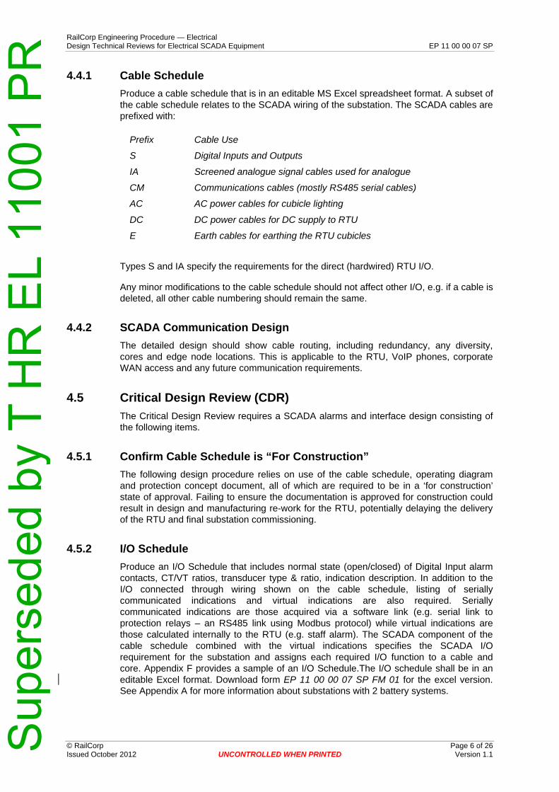
4.4.1 Cable Schedule Produce a cable schedule that is in an editable MS Excel spreadsheet format. A subset of the cable schedule relates to the SCADA wiring of the substation. The SCADA cables are prefixed with:
Prefix Cable Use
S Digital Inputs and Outputs
IA Screened analogue signal cables used for analogue
CM Communications cables (mostly RS485 serial cables)
AC AC power cables for cubicle lighting
DC DC power cables for DC supply to RTU
E Earth cables for earthing the RTU cubicles
Types S and IA specify the requirements for the direct (hardwired) RTU I/O.
Any minor modifications to the cable schedule should not affect other I/O, e.g. if a cable is deleted, all other cable numbering should remain the same.
4.4.2 SCADA Communication Design The detailed design should show cable routing, including redundancy, any diversity, cores and edge node locations. This is applicable to the RTU, VoIP phones, corporate WAN access and any future communication requirements.
4.5 Critical Design Review (CDR) The Critical Design Review requires a SCADA alarms and interface design consisting of the following items.
4.5.1 Confirm Cable Schedule is “For Construction” The following design procedure relies on use of the cable schedule, operating diagram and protection concept document, all of which are required to be in a ‘for construction’ state of approval. Failing to ensure the documentation is approved for construction could result in design and manufacturing re-work for the RTU, potentially delaying the delivery of the RTU and final substation commissioning.
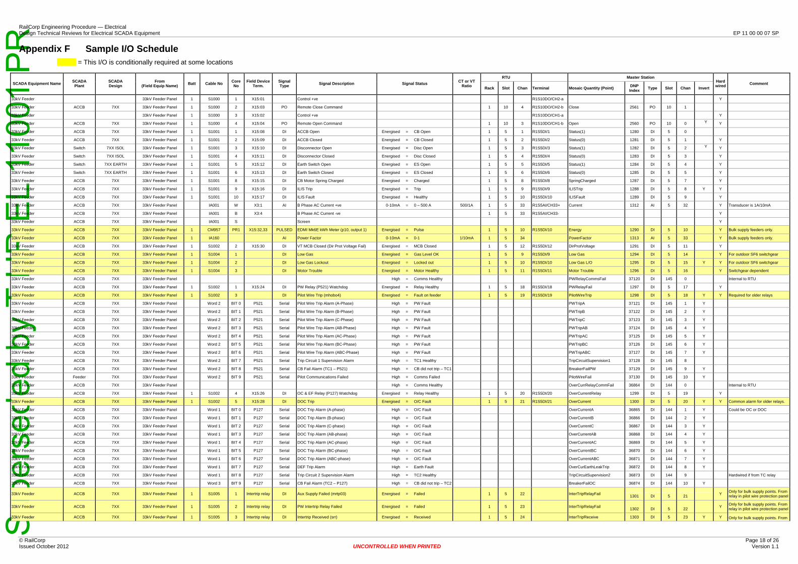
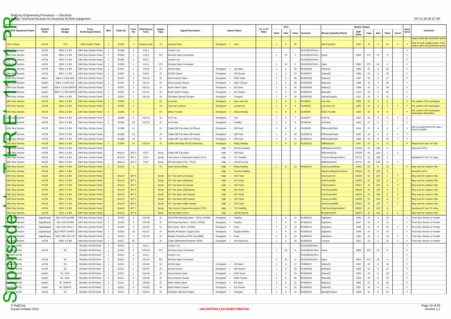
4.5.2 I/O Schedule Produce an I/O Schedule that includes normal state (open/closed) of Digital Input alarm contacts, CT/VT ratios, transducer type & ratio, indication description. In addition to the I/O connected through wiring shown on the cable schedule, listing of serially communicated indications and virtual indications are also required. Serially communicated indications are those acquired via a software link (e.g. serial link to protection relays – an RS485 link using Modbus protocol) while virtual indications are those calculated internally to the RTU (e.g. staff alarm). The SCADA component of the cable schedule combined with the virtual indications specifies the SCADA I/O requirement for the substation and assigns each required I/O function to a cable and core. Appendix F provides a sample of an I/O Schedule.The I/O schedule shall be in an editable Excel format. Download form EP 11 00 00 07 SP FM 01 for the excel version. See Appendix A for more information about substations with 2 battery systems.
© RailCorp Page 6 of 26 Issued October 2012 UNCONTROLLED WHEN PRINTED Version 1.1
Sup
erse
ded
by T
HR
EL
1100
1 P
RRailCorp Engineering Procedure — Electrical Design Technical Reviews for Electrical SCADA Equipment EP 11 00 00 07 SP
The SCADA alarms and controls to be provided for a location will largely conform to the standard I/O complement that has been provided at locations already in service in the RailCorp network. However, where a SCADA point is required for a new type of equipment or to alarm a condition not previously alarmed in the system, instructions detailing the meaning and use of the point will need to be provided to EOC. This document will give a description of the indication and instructions of required actions by the Electrical System Operators when the alarm occurs in service.
4.5.3 Confirm RTU Supplier RailCorp has determined a number of RTUs from different suppliers that have been proven to work satisfactorily with the Master Station. The suppliers are Invensys, Logica and Kingfisher. As at October 2011 Railcorp has a supply agreement with Invensys for the supply of complete RTU assemblies (RTU, ancillary equipment, cabinets and cable marshalling area). The supply agreement is current to 12 June 2012, and thereafter, for an additional year if required. This supply agreement is entered in RailCorp’s procurement system, Ariba, as a set of “Catalogue Items”. See Appendix D for more information about procuring RTUs using Ariba. RailCorp will procure the RTU.
4.5.4 RTU Size The RailCorp SCADA section will determine the number of racks, I/O cards and marshalling terminals from the I/O Schedule and Cable Schedule. Once the quantity and type of each module required has been determined, the number of racks required can be determined. Multiple racks are interconnected using optical links (‘optonets’) to form a single logical RTU. Physical I/O points in the RTU are then identified by specifying Rack, Slot and Channel numbers. See Appendix A for more information.
4.5.5 RTU and Marshalling Cabinet Layout The RailCorp SCADA section will arrange the cabinet layout.
RTUs are assembled as RTU/marshalling panel assemblies with the marshalling cabinet housing terminations for the field cables. A dedicated terminal strip is provided for the termination of each field cable with a terminal provided and numbered in sequence for each core of the cable. The strip is labelled according to the cable number and its function. The terminals in these strips are ‘disconnect’ links, enabling complete isolation of the plant from the RTU.
Additionally, the marshalling cabinet houses another set of terminal strips, which relates to each I/O module in the RTU assembly and is in sequence e.g. R1S3DI1 down to R1S3DI32 for an Invensys DI module with 32 inputs. The terminals in these strips are through (not disconnect) links.
Physical assignment of an I/O field function to a particular I/O point in the RTU is completed by installing wiring (Cross Wiring) between the field wiring terminal strips and the RTU-centric terminal strips. From the cable schedule, the quantity and size of the field wiring terminal strips required is known and from the I/O specification of the RTU determined earlier, the number and quantity of RTU terminals is known. Using this information, the marshalling panel terminal layout can be performed. This arrangement of terminals facilitates changes if required on site, where cross wiring can be altered without changing either RTU or field cabling.
The marshalling panel is laid out with field cabling passing up large slotted cable ducts in the centre of the cabinet and terminated onto the field terminals laid out on either side of the ducts. The RTU module terminals are arranged outside the field terminals. See Appendix A for more information.
© RailCorp Page 7 of 26 Issued October 2012 UNCONTROLLED WHEN PRINTED Version 1.1

Sup
erse
ded
by T
HR
EL
1100
1 P
RRailCorp Engineering Procedure — Electrical Design Technical Reviews for Electrical SCADA Equipment EP 11 00 00 07 SP
4.5.6 Marshalling Cabinet Cross Wiring The RailCorp SCADA section will produce the cross wiring schedule.
Cross wiring needs to be installed in the RTU between each non-spare field cable core on the field terminal strip and the assigned I/O channel on the RTU terminal strip for that I/O function to complete the factory built RTU to match the master station configuration. This cross wiring can be done so that consecutive field cable cores are where possible wired to consecutive RTU module channels minimising the length and complexity of wiring within the marshalling panel.
Each specified I/O is assigned to a particular RTU channel using the I/O Schedule. This is done using a dedicated master station configuration tool, the output of which is downloaded into the master station to modify the master station configuration to include the requirements for the new substation. This tool can also output an Excel report, which is used to specify the required cross wiring to the manufacturer. This is done using a previously completed substation as a template, which helps identify omitted or unnecessary I/O functions. Note that this assignment of I/O functions to channels is arbitrary although some consideration is given to different substation batteries and separating redundant feeder I/O onto different modules and/or racks to allow limited operation of the substation SCADA system in the case of individual, single module and/or rack failure. Where possible RTU channels should be allocated to functions in the same order as the functions appear in the cable schedule. This minimises wiring length, the possibility of wiring errors and the complexity of the documentation provided to the RTU manufacturer.
4.6 Approved for Construction There should be only minor changes to the I/O Schedule and RTU design at this stage.
4.7 Construction
4.7.1 Order RTU The order is placed with the RTU supplier by RailCorp. This includes cabinets, communications power supplies and all ancillary equipment. The RTU must be ordered 16 weeks before it is required to be installed. This provides 8 weeks for the order and fit out of the RTU and a further 8 weeks for cabinet fit out and wiring. The manufacturer is provided with the required RTU layout, the marshalling cabinet layout and the cross wiring schedule. RTU manufacture can commence with this information along with specification of some standard provisions such as communications power supplies, dummy circuit breaker and supply bus arrangements. See Appendix D for more information about procuring an RTU using Ariba.
The RTU will undergo Factory Acceptance Testing, which may be witnessed by RailCorp, at the manufacturer’s premises before delivery to site. Under the supply agreement with RailCorp, a standard “Inspection and Test Plan” documents these procedures and an “RTU Release Certificate” is signed, permitting delivery to site.
© RailCorp Page 8 of 26 Issued October 2012 UNCONTROLLED WHEN PRINTED Version 1.1

Sup
erse
ded
by T
HR
EL
1100
1 P
RRailCorp Engineering Procedure — Electrical Design Technical Reviews for Electrical SCADA Equipment EP 11 00 00 07 SP
4.7.2 Prepare Master Station RailCorp’s SCADA section will modify the Master Station’s configuration database for the new RTU.
The configuration produced by the Master Station SCADA Configuration Tool is used to add all the I/O for the new RTU into the Master Station’s database. After this is done, SCADA operator screen layouts (schematics) can be completed ready for pre-commissioning.
4.7.3 RTU Installed The RTU and marshalling cabinets will be delivered to site and installed (field wiring will be connected to the field terminals in the marshalling cabinet). Field cable terminations located within an RTU marshalling cubicle shall define the point of separation between the Electrical SCADA RTU and the substation electrical system.
4.7.4 Communications Installed RailCorp’s Communications and Control Section (C&CS) will arrange the installation of communications for the SCADA system. C&CS will then test and verify the links.
4.7.5 Configure RTU RailCorp’s SCADA Technicians will prepare the configuration required for the RTU from the detail provided to the manufacturer and the Master Station SCADA Configuration Tool. This is then loaded into a test RTU facility and checked against the master station configuration to ensure the master station can satisfactorily scan the test RTU.
The configuration of the test RTU is then transferred to the target RTU on site. The RTU can then be scanned by the Master Station to confirm the communication configuration is correct.
4.7.6 Pre-commissioning Pre-commissioning is done to confirm the SCADA RTU is configured correctly by testing between the RTU and the Master Station. This is done in coordination with the SCADA section at EOC and verifies connection from field terminals to the master station. During this test, the disconnect links in the RTU remain open.
The SCADA RTU needs to be in service before any field testing is done. This prevents field equipment being checked twice.
© RailCorp Page 9 of 26 Issued October 2012 UNCONTROLLED WHEN PRINTED Version 1.1
Sup
erse
ded
by T
HR
EL
1100
1 P
RRailCorp Engineering Procedure — Electrical Design Technical Reviews for Electrical SCADA Equipment EP 11 00 00 07 SP
4.7.7 Commissioning Commissioning is an end to end check, from field equipment to the Master Station. This confirms field equipment, field wiring and cross wiring are all correct. This is done by project staff in coordination with the SCADA section at EOC. Once the indication is operational the disconnect links are left closed.
Records need to be kept both in the field and at EOC of the progress of commissioning. A summary report should be completed after commissioning that lists all the indications that have not been tested or are faulty and give comments including expected date of completion and person responsible for rectification. See Appendix E for a sample commissioning sheet.
For a substation to be commissioned all high priority indications (circuit breaker status and control and protection monitoring alarms) must be in service.
4.7.8 ‘As Built’ Drawings After commissioning the ‘as built’ drawings should be supplied. These include cable schedule, I/O schedule and RTU drawings. The RTU drawings shall be corrected to “as built” status and include the following for each site:
• RTU & Marshalling Cabinet General Arrangement • RTU & Marshalling Cabinet Details of Materials • RTU & Marshalling Cabinet Diagram of Connections • RTU & Marshalling Cabinet Terminal Arrangement
© RailCorp Page 10 of 26 Issued October 2012 UNCONTROLLED WHEN PRINTED Version 1.1

Sup
erse
ded
by T
HR
EL
1100
1 P
RRailCorp Engineering Procedure — Electrical Design Technical Reviews for Electrical SCADA Equipment EP 11 00 00 07 SP
Appendix A RTU Layout
I/O Arrangement at Dual Battery Substations At bulk supply points and major substations there are two independent, isolated battery systems. At these locations the RTU will be supplied from Battery No.1. However, the indications may be supplied from either battery system. It is imperative that these two systems are not connected through the RTU
Battery No.1 will be the supply for most indications. The exception to this is for DCCBs, which will normally be split so that half are supplied from Battery No.1 and half are supplied from Battery No.2.
The marshalling terminals shall be arranged so there is clear definition between indications from Battery No.1 and those from Battery No.2, so as to avoid inadvertent cross connection in the field.
RTU and Marshalling Cabinet Layout To summarise the terminal and wiring arrangement:
Terminals on the RTU terminal strip are arranged to suit the RTU hardware modules. The digital inputs on Invensys RTUs are arranged on modules with 32 DI channels. Therefore the terminals on the RTU terminal strips which relate to the digital inputs on the ADI module in slot 4 in the example have 32 terminals numbered sequentially with each terminal number corresponding to the RTU module input number. Two additional terminals are provided for 125V negative connection from the RTU module.
Terminals on the field terminal strip are arranged in blocks to suit the field cables. For each field cable block, a terminal is provided for each core of the cable, so for the example cable S005, which is a 16 core cable with earth, 17 terminals are provided, numbered in sequence 1 to 16 with each (numbered) core of the cable connected to the correspondingly numbered terminal of the block and earth connection.
© RailCorp Page 11 of 26 Issued October 2012 UNCONTROLLED WHEN PRINTED Version 1.1

Sup
erse
ded
by T
HR
EL
1100
1 P
RRailCorp Engineering Procedure — Electrical Design Technical Reviews for Electrical SCADA Equipment EP 11 00 00 07 SP
Appendix B Invensys RTUs The supply agreement current at October 2011 for RTUs provides for the following modules:
• ADI modules: These provide 32 digital inputs and 4 analogue inputs on the module.
• DO modules: These provide 8 digital outputs (4 trip/close pairs) on the module. • AI module: These provide 20 analogue inputs on the module. However they are
normally not required, as the ADI cards provide digital and analogue inputs in the typically used ratio.
• Serial Input module: This provides 4 isolated channels of RS485 inputs, and 4 non-isolated channels.
• Multi I/O modules: These provide mixtures of AIs, DIs, and DOs.
The Invensys RTUs comprise of racks of 12 slots (although 1 and 5 slot racks are also available), 10 of which are available for I/O modules because slots 1 and 2 are reserved for power supply and CPU respectively.
© RailCorp Page 12 of 26 Issued October 2012 UNCONTROLLED WHEN PRINTED Version 1.1

Sup
erse
ded
by T
HR
EL
1100
1 P
RRailCorp Engineering Procedure — Electrical Design Technical Reviews for Electrical SCADA Equipment EP 11 00 00 07 SP
Appendix C General and Sample Drawings There are a number of drawings that relate to the installation of RTUs in substations. Some of these are general drawings applicable to all locations and others are sample arrangements.
Drawing No. Title Description
EL0204559 General - Substations Staff Access, Emergency Lighting, A/C & HWU Control Schematic
Staff switch, door reeds, control wiring
EL0435527 Toongabbie SS Electrical Communication Cabling Block Diagram
Communications cabling with C&CS fibre for protection pilots
EL0476114 Art Gallery SS Electrical Communication Cabling Block Diagram
Communications cabling using feeder fibre for protection pilots
EL0360897 Waverton SS Electrical Communication Cabling Block Diagram
Communications cabling using copper for protection pilots
EL0493835 Ashfield SS RTU and Marshalling cabinet General Arrangement
RTU General arrangement (single cubicle, front and rear access, terminals on back of RTU)
EL0015242 Strathfield SS RTU and Marshalling cabinet General Arrangement
RTU General arrangement (triple cubicle, front access only, terminals on back of RTU, RTU on swing frame)
EL0493837 EL0493838
Ashfield SS RTU & Marshalling Cabinet Detail of Materials
Bill of Materials
(Two Sheets)
EL0493839 EL0493840 EL0493841
Ashfield SS RTU & Marshalling Cabinet Diagram of Connections (Three sheets)
Typical connection diagram (Power supply, Dummy Circuit Breaker)
EL0493836 Ashfield SS RTU & Marshalling Cabinet Terminal Arrangement
Terminal arrangement
© RailCorp Page 13 of 26 Issued October 2012 UNCONTROLLED WHEN PRINTED Version 1.1

Sup
erse
ded
by T
HR
EL
1100
1 P
RRailCorp Engineering Procedure — Electrical Design Technical Reviews for Electrical SCADA Equipment EP 11 00 00 07 SP
Appendix D Procurement of RTU/Marshalling Cubicles using Ariba
The supply agreement with Invensys is entered in RailCorp’s procurement system, Ariba, as a set of “Catalogue Items”. It can be accessed by locating the supplier “Invensys Process Systems.” There are 81 items available to specify an RTU/marshalling cubicle combination.
The prices in the Supply Agreement are for complete RTU assemblies including the following:
• RTU compatible with RailCorp’s master station, capable of being scanned using either DNP (on fibre) or pilot wire.
• Cubicles – standard size 1800mmW x 600mmD x 2100mmH front and back access, bottom entry, or 2400mmW x 500mmD x 2100mmH, front access only, bottom entry, or wall mount for smaller locations.
• Marshalling terminals using disconnect links where specified • All power supplies, including 48V supplies for communications purposes • Dummy circuit breaker • Blanking panels to cover empty card slots to ensure EMC compliance • AC connection for lights and GPO inside cubicles • Provision of sequential termination of individual RTU and field cable cores. • Testing at the nominated supply voltage • Delivery to a nominated RailCorp location • Supply of documentation and manuals for operation and maintenance of the
equipment
Pricing is given for RTUs with several different I/O complements. Price modifiers are given to increment or decrement the I/O to suit the location. Noting that an ADI card (analogue digital card) has 32 digital inputs and 4 analogue inputs, a DO card contains 8 digital outputs with clean contacts for each output, a serial card is equipped with 4 x RS485 isolated channels, and there are 10 x I/O cards per file, the RTUs priced are:
• Item1.13/B2.2.1 – 6 x ADI, 3 x DO, 1 serial - 1 x card files • Item 1.1/B2.2.1 – 8 x ADI, 4 x DO, 1 serial – 2 x card files • Item 1.11/B2.2.1 – 10 ADI, 5 x DO, 1 serial – 2 x card files • Item 1.8/B2.2.1 – 2 x ADI, 1 x DO – 1 x card files • Item 1.14/B2.2.1 – 2 x ADI, 2 x DO – 1 x card files.
Thus the first item is equipped with 6 x 32 or 192 digital inputs, 24 analogue inputs, 24 control outputs, and 4 isolated serial RS485 ports. The most commonly used increments and decrements priced are:
• Item 2.1/B2.2.2 – Adds 1 x ADI card plus cabling and terminals • Item 2.2/B2.2.2 – Subtracts 1 x ADI card plus cabling and terminals • Item 2.5/B2.2.2 - Adds 1 x DO card plus cabling and terminals • Item 2.6/B2.2.2 – Subtracts 1 x DO card plus cabling and terminals • Item 2.7/B2.2.2 – Adds 1 serial card plus cabling and terminals • Item 2.8/B2.2.2 – Subtracts 1 x serial card plus cabling and terminals • Item 2.17/B2.2.2 – Adds 1 x 10 I/O slot chassis plus CPU and power supply cards • Item 2.18/B2.2.2 – Subtracts 1 x 10 I/O slot chassis plus CPU and power. • Item 2.23/B2.2.2 – Converts 1 x ADI card to a universal ADI card (new type)
Individual items are also priced as spare parts, which are delivered as separate items. They are numbered Item 5.1/B2.2.5 through to Item 5.20/B2.2.5, and are described in ARIBA.
© RailCorp Page 14 of 26 Issued October 2012 UNCONTROLLED WHEN PRINTED Version 1.1

Sup
erse
ded
by T
HR
EL
1100
1 P
RRailCorp Engineering Procedure — Electrical Design Technical Reviews for Electrical SCADA Equipment EP 11 00 00 07 SP
(The ARIBA price lists also include items mounted on an aluminium “gear plates”. These are RTU subassemblies made to replace an existing RTU leaving the cubicle intact, and are not applicable to new locations. These were included to facilitate the RTU upgrade program. Items range from item 3.1/B2.2.3 to item 3.30/B2.2.3 and item 4.1/B2.2.4 to item 4.14/B2.2.4. These items do not include cubicles, GPOs & lighting, and have different methods for inclusion of marshalling terminals)
Pricing in this Supply Agreement is subject to escalation in accordance with agreed indices.
• Pricing listed in ARIBA was applicable from 12 June 2009 to 11 June 2010. • Pricing from 12 June 2010 to 11 June 2011 has escalation of 1.18% applied • Pricing from 12 June 2011 to 11 June 2012 has escalation of 3.43% applied • Pricing from 12 June 2012 to 11 June 2013 is yet to be advised.
When the subtotal of the order is determined, a new item is selected - Miscellaneous parts & services (set to $1.00) and an escalation quantity is entered to determine the current price.
Example A:
A new RTU requires 212 digital inputs, 33 analogue inputs, 35 digital outputs and 3 serial channels. The cubicle is a standard suite with back and front access, bottom entry. Power supply is a single 125VDC. Delivery is required on site by 1 September 2011. Spares are to be provided at 20%. The timing requires an order by 1 May 2011
No. of digital input points is (212+20%)/32 or 9.9375 cards – select 10 ADI cards. 10 x ADI cards provide 40 analogue inputs, which is adequate to handle 33 plus 7 spares. No. of digital output points is (35+20%) +2 for dummy CB, which is 44/8 which is 5.5 cards - select 6 cards. 1 x serial card is adequate. At 10 I/O cards per file, this will require 2 I/O files. Item 1.11 in list above contains 10 x ADI, 5 x DO and 1 x Serial. Therefore we need to add 1 x DO card to this RTU – select item 3 in the list of RTUs and 1 off item 3 in the list of increments and decrements. This gives:
Item1: Base RTU with 10 x ADI, 5 x DO and 1 serial card Item2: Add 1 x DO card Item 3: add 1 year escalation at 1.18%
Note: The RTU and field terminals need analysis to ensure that the layout fits adequately into the cubicle space. This will be done by the manufacturer in a set of drawings done to be “approved for manufacture” status, including GA, BOM and terminal layout.
© RailCorp Page 15 of 26 Issued October 2012 UNCONTROLLED WHEN PRINTED Version 1.1
Sup
erse
ded
by T
HR
EL
1100
1 P
RRailCorp Engineering Procedure — Electrical Design Technical Reviews for Electrical SCADA Equipment EP 11 00 00 07 SP
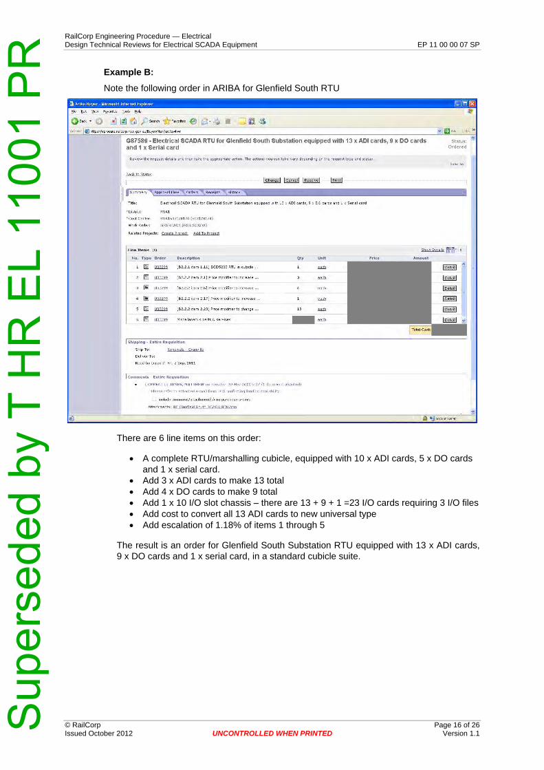
Example B:
Note the following order in ARIBA for Glenfield South RTU
There are 6 line items on this order:
• A complete RTU/marshalling cubicle, equipped with 10 x ADI cards, 5 x DO cards and 1 x serial card.
• Add 3 x ADI cards to make 13 total • Add 4 x DO cards to make 9 total • Add 1 x 10 I/O slot chassis – there are 13 + 9 + 1 =23 I/O cards requiring 3 I/O files • Add cost to convert all 13 ADI cards to new universal type • Add escalation of 1.18% of items 1 through 5
The result is an order for Glenfield South Substation RTU equipped with 13 x ADI cards, 9 x DO cards and 1 x serial card, in a standard cubicle suite.
© RailCorp Page 16 of 26 Issued October 2012 UNCONTROLLED WHEN PRINTED Version 1.1
Sup
erse
ded
by T
HR
EL
1100
1 P
R
© RailCorp Page 17 of 26 Issued October 2012 UNCONTROLLED WHEN PRINTED Version 1.1
RailCorp Engineering Procedure — Electrical Design Technical Reviews for Electrical SCADA Equipment EP 11 00 00 07 SP
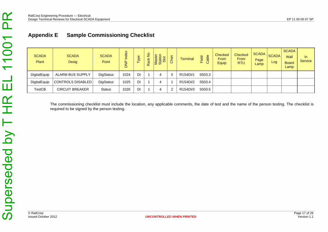
Appendix E Sample Commissioning Checklist
SCADA
Plant
SCADA
Desig
SCADA
Point
DN
P In
dex
Type
Rac
k N
o
Mas
ter
Sta
tion
Slo
t
Cha
n
Terminal
Fiel
d
Cab
le Checked
From Equip
Checked From RTU
SCADA
Page Lamp
SCADA
Log
SCADA
Wall
Board Lamp
In Service
DigitalEquip ALARM BUS SUPPLY DigStatus 1024 DI 1 4 0 R1S4DI/1 S503.3
DigitalEquip CONTROLS DISABLED DigStatus 1025 DI 1 4 1 R1S4DI/2 S503.4
TestCB CIRCUIT BREAKER Status 1026 DI 1 4 2 R1S4DI/3 S503.5
The commissioning checklist must include the location, any applicable comments, the date of test and the name of the person testing. The checklist is required to be signed by the person testing.
Sup
erse
ded
by T
HR
EL
1100
1 P
R
© RailCorp Page 18 of 26 Issued October 2012 UNCONTROLLED WHEN PRINTED Version 1.1
RailCorp Engineering Procedure — Electrical Design Technical Reviews for Electrical SCADA Equipment EP 11 00 00 07 SP
Appendix F Sample I/O Schedule = This I/O is conditionally required at some locations
SCADA Equipment Name SCADA Plant
SCADA Design
From (Field Equip Name) Batt Cable No Core
No Field Device
Term. Signal Type Signal Description Signal Status CT or VT
Ratio
RTU Master Station Hard wired Comment
Rack Slot Chan Terminal Mosaic Quantity (Point) DNP Index Type Slot Chan Invert
33kV Feeder 33kV Feeder Panel 1 S1000 1 X15:01 Control +ve R1S10DO/CH2-a Y
33kV Feeder ACCB 7XX 33kV Feeder Panel 1 S1000 2 X15:03 PO Remote Close Command 1 10 4 R1S10DO/CH2-b Close 2561 PO 10 1
Y 33kV Feeder 33kV Feeder Panel 1 S1000 3 X15:02 Control +ve R1S10DO/CH1-a Y
33kV Feeder ACCB 7XX 33kV Feeder Panel 1 S1000 4 X15:04 PO Remote Open Command 1 10 3 R1S10DO/CH1-b Open 2560 PO 10 0 Y
33kV Feeder ACCB 7XX 33kV Feeder Panel 1 S1001 1 X15:08 DI ACCB Open Energised = CB Open 1 5 1 R1S5DI/1 Status(1) 1280 DI 5 0
Y 33kV Feeder ACCB 7XX 33kV Feeder Panel 1 S1001 2 X15:09 DI ACCB Closed Energised = CB Closed 1 5 2 R1S5DI/2 Status(0) 1281 DI 5 1 Y
33kV Feeder Switch 7XX ISOL 33kV Feeder Panel 1 S1001 3 X15:10 DI Disconnector Open Energised = Disc Open 1 5 3 R1S5DI/3 Status(1) 1282 DI 5 2 Y
33kV Feeder Switch 7XX ISOL 33kV Feeder Panel 1 S1001 4 X15:11 DI Disconnector Closed Energised = Disc Closed 1 5 4 R1S5DI/4 Status(0) 1283 DI 5 3 Y
33kV Feeder Switch 7XX EARTH 33kV Feeder Panel 1 S1001 5 X15:12 DI Earth Switch Open Energised = ES Open 1 5 5 R1S5DI/5 Status(1) 1284 DI 5 4 Y
33kV Feeder Switch 7XX EARTH 33kV Feeder Panel 1 S1001 6 X15:13 DI Earth Switch Closed Energised = ES Closed 1 5 6 R1S5DI/6 Status(0) 1285 DI 5 5 Y
33kV Feeder ACCB 7XX 33kV Feeder Panel 1 S1001 8 X15:15 DI CB Motor Spring Charged Energised = Charged 1 5 8 R1S5DI/8 SpringCharged 1287 DI 5 7 Y
33kV Feeder ACCB 7XX 33kV Feeder Panel 1 S1001 9 X15:16 DI ILIS Trip Energised = Trip 1 5 9 R1S5DI/9 ILISTrip 1288 DI 5 8 Y Y
33kV Feeder ACCB 7XX 33kV Feeder Panel 1 S1001 10 X15:17 DI ILIS Fault Energised = Healthy 1 5 10 R1S5DI/10 ILISFault 1289 DI 5 9 Y
33kV Feeder ACCB 7XX 33kV Feeder Panel IA001 W X3:1 AI B Phase AC Current +ve 0-10mA = 0 – 500 A 500/1A 1 5 33 R1S5AI/CH33+ Current 1312 AI 5 32 Y Transducer is 1A/10mA
33kV Feeder ACCB 7XX 33kV Feeder Panel IA001 B X3:4 B Phase AC Current -ve 1 5 33 R1S5AI/CH33 Y
33kV Feeder ACCB 7XX 33kV Feeder Panel IA001 S Screen Y
33kV Feeder ACCB 7XX 33kV Feeder Panel 1 CM957 PR1 X15:32,33 PULSED EDMI Mk6E kWh Meter (p10, output 1) Energised = Pulse 1 5 10 R1S5DI/10 Energy 1290 DI 5 10 Y Bulk supply feeders only.
33kV Feeder ACCB 7XX 33kV Feeder Panel 1 IA160 AI Power Factor 0-10mA = 0-1 1/10mA 1 5 34 PowerFactor 1313 AI 5 33 Y Bulk supply feeders only.
33kV Feeder ACCB 7XX 33kV Feeder Panel 1 S1002 2 X15:30 DI VT MCB Closed (Dir Prot Voltage Fail) Energised = MCB Closed 1 5 12 R1S5DI/12 DirProtVoltage 1291 DI 5 11 Y
33kV Feeder ACCB 7XX 33kV Feeder Panel 1 S1004 1 DI Low Gas Energised = Gas Level OK 1 5 9 R1S5DI/9 Low Gas 1294 DI 5 14 Y For outdoor SF6 switchgear
33kV Feeder ACCB 7XX 33kV Feeder Panel 1 S1004 2 DI Low Gas Lockout Energised = Locked out 1 5 10 R1S5DI/10 Low Gas L/O 1295 DI 5 15 Y Y For outdoor SF6 switchgear
33kV Feeder ACCB 7XX 33kV Feeder Panel 1 S1004 3 DI Motor Trouble Energised = Motor Healthy 1 5 11 R1S5DI/11 Motor Trouble 1296 DI 5 16 Y Switchgear dependent
33kV Feeder ACCB 7XX 33kV Feeder Panel High = Comms Healthy PWRelayCommsFail 37120 DI 145 0 Internal to RTU
33kV Feeder ACCB 7XX 33kV Feeder Panel 1 S1002 1 X15:24 DI PW Relay (P521) Watchdog Energised = Relay Healthy 1 5 18 R1S5DI/18 PWRelayFail 1297 DI 5 17 Y
33kV Feeder ACCB 7XX 33kV Feeder Panel 1 S1002 3 DI Pilot Wire Trip (mhobo4) Energised = Fault on feeder 1 5 19 R1S5DI/19 PilotWireTrip 1298 DI 5 18 Y Y Required for older relays
33kV Feeder ACCB 7XX 33kV Feeder Panel Word 2 BIT 0 P521 Serial Pilot Wire Trip Alarm (A-Phase) High = PW Fault PWTripA 37121 DI 145 1 Y
33kV Feeder ACCB 7XX 33kV Feeder Panel Word 2 BIT 1 P521 Serial Pilot Wire Trip Alarm (B-Phase) High = PW Fault PWTripB 37122 DI 145 2 Y
33kV Feeder ACCB 7XX 33kV Feeder Panel Word 2 BIT 2 P521 Serial Pilot Wire Trip Alarm (C-Phase) High = PW Fault PWTripC 37123 DI 145 3 Y
33kV Feeder ACCB 7XX 33kV Feeder Panel Word 2 BIT 3 P521 Serial Pilot Wire Trip Alarm (AB-Phase) High = PW Fault PWTripAB 37124 DI 145 4 Y
33kV Feeder ACCB 7XX 33kV Feeder Panel Word 2 BIT 4 P521 Serial Pilot Wire Trip Alarm (AC-Phase) High = PW Fault PWTripAC 37125 DI 145 5 Y
33kV Feeder ACCB 7XX 33kV Feeder Panel Word 2 BIT 5 P521 Serial Pilot Wire Trip Alarm (BC-Phase) High = PW Fault PWTripBC 37126 DI 145 6 Y
33kV Feeder ACCB 7XX 33kV Feeder Panel Word 2 BIT 6 P521 Serial Pilot Wire Trip Alarm (ABC-Phase) High = PW Fault PWTripABC 37127 DI 145 7 Y
33kV Feeder ACCB 7XX 33kV Feeder Panel Word 2 BIT 7 P521 Serial Trip Circuit 1 Supervision Alarm High = TC1 Healthy TripCircuitSupervision1 37128 DI 145 8
33kV Feeder ACCB 7XX 33kV Feeder Panel Word 2 BIT 8 P521 Serial CB Fail Alarm (TC1 – P521) High = CB did not trip – TC1 BreakerFailPW 37129 DI 145 9 Y
33kV Feeder Feeder 7XX 33kV Feeder Panel Word 2 BIT 9 P521 Serial Pilot Communications Failed High = Comms Failed PilotWireFail 37130 DI 145 10 Y
33kV Feeder ACCB 7XX 33kV Feeder Panel High = Comms Healthy OverCurrRelayCommFail 36864 DI 144 0 Internal to RTU
33kV Feeder ACCB 7XX 33kV Feeder Panel 1 S1002 4 X15:26 DI OC & EF Relay (P127) Watchdog Energised = Relay Healthy 1 5 20 R1S5DI/20 OverCurrentRelay 1299 DI 5 19 Y
33kV Feeder ACCB 7XX 33kV Feeder Panel 1 S1002 5 X15:28 DI DOC Trip Energised = O/C Fault 1 5 21 R1S5DI/21 OverCurrent 1300 DI 5 20 Y Y Common alarm for older relays.
33kV Feeder ACCB 7XX 33kV Feeder Panel Word 1 BIT 0 P127 Serial DOC Trip Alarm (A-phase) High = O/C Fault OverCurrentA 36865 DI 144 1 Y Could be OC or DOC
33kV Feeder ACCB 7XX 33kV Feeder Panel Word 1 BIT 1 P127 Serial DOC Trip Alarm (B-phase) High = O/C Fault OverCurrentB 36866 DI 144 2 Y
33kV Feeder ACCB 7XX 33kV Feeder Panel Word 1 BIT 2 P127 Serial DOC Trip Alarm (C-phase) High = O/C Fault OverCurrentC 36867 DI 144 3 Y
33kV Feeder ACCB 7XX 33kV Feeder Panel Word 1 BIT 3 P127 Serial DOC Trip Alarm (AB-phase) High = O/C Fault OverCurrentAB 36868 DI 144 4 Y
33kV Feeder ACCB 7XX 33kV Feeder Panel Word 1 BIT 4 P127 Serial DOC Trip Alarm (AC-phase) High = O/C Fault OverCurrentAC 36869 DI 144 5 Y
33kV Feeder ACCB 7XX 33kV Feeder Panel Word 1 BIT 5 P127 Serial DOC Trip Alarm (BC-phase) High = O/C Fault OverCurrentBC 36870 DI 144 6 Y
33kV Feeder ACCB 7XX 33kV Feeder Panel Word 1 BIT 6 P127 Serial DOC Trip Alarm (ABC-phase) High = O/C Fault OverCurrentABC 36871 DI 144 7 Y
33kV Feeder ACCB 7XX 33kV Feeder Panel Word 1 BIT 7 P127 Serial DEF Trip Alarm High = Earth Fault OverCurEarthLeakTrip 36872 DI 144 8 Y
33kV Feeder ACCB 7XX 33kV Feeder Panel Word 1 BIT 8 P127 Serial Trip Circuit 2 Supervision Alarm High = TC2 Healthy TripCircuitSupervision2 36873 DI 144 9 Hardwired if from TC relay
33kV Feeder ACCB 7XX 33kV Feeder Panel Word 3 BIT 9 P127 Serial CB Fail Alarm (TC2 – P127) High = CB did not trip – TC2 BreakerFailOC 36874 DI 144 10 Y
33kV Feeder ACCB 7XX 33kV Feeder Panel 1 S1005 1 Intertrip relay DI Aux Supply Failed (mrtp03) Energised = Failed 1 5 22 InterTripRelayFail 1301 DI 5 21 Y Only for bulk supply points. From relay in pilot wire protection panel
33kV Feeder ACCB 7XX 33kV Feeder Panel 1 S1005 2 Intertrip relay DI PW Intertrip Relay Failed Energised = Failed 1 5 23 InterTripRelayFail 1302 DI 5 22 Y Only for bulk supply points. From relay in pilot wire protection panel
33kV Feeder ACCB 7XX 33kV Feeder Panel 1 S1005 3 Intertrip relay DI Intertrip Received (srr) Energised = Received 1 5 24 InterTripReceive 1303 DI 5 23 Y Y Only for bulk supply points. From
Sup
erse
ded
by T
HR
EL
1100
1 P
R RTU Mast Stater ion
SCADA SCADA From Core Field Device Signal CT or VT Hard SCADA Equipment Name Batt Cable No Signal Description Signal Status Comment Plant Design (Field Equip Name) No Term. Type Ratio DNP wired Rack Slot Chan Terminal Mo Qusaic antity (P oint) Type Slot Chan Invert Index relay in pilot wire protection panel
Only for bulk supply points. From 33kV Feeder ACCB 7XX 33kV Feeder Panel 1 S1005 4 Intertrip relay DI Intertrip Send Energised = Sent 1 5 25 InterTripSend 1304 DI 5 24 Y Y relay in pilot wire protection panel
33kV Bus Section ACCB 33KV 1-2 BS 33kV Bus Section Panel 1 S1006 1 X15:1 Control +ve R1S10DO/CH4-a Y
33kV Bus Section ACCB 33KV 1-2 BS 33kV Bus Section Panel 1 S1006 2 X15:3 PO Remote Close Command 1 10 4 R1S10DO/CH4-b Close 2563 PO Y10 3
33kV Bus Section ACCB 33KV 1-2 BS 33kV Bus Section Panel 1 S1006 3 X15:2 Control +ve R1S10DO/CH3-a Y
33kV Bus Section ACCB 33KV 1-2 BS 33kV Bus Section Panel 1 S1006 4 X15:4 PO Remote Open Command 1 10 3 R1S10DO/CH3-b Open 2562 PO 10 2 Y
33kV Bus Section ACCB 33KV 1-2 BS 33kV Bus Section Panel 1 S1007 1 X15:8 DI ACCB Open Energised = CB Open 1 5 26 R1S5DI/26 Status(1) 130 DI5 5 Y25
33kV Bus Section ACCB 33KV 1-2 BS 33kV Bus Section Panel 1 S1007 2 X15:9 DI ACCB Closed Energised = CB Closed 1 5 27 R1S5DI/27 Status(0) 130 DI6 5 Y26
33kV Bus Section Switch 33KV 1-2 BS ISOL 33kV Bus Section Panel 1 S1007 3 X15:10 DI Disconnector Open Energised = DISC Open 1 5 R 28 1S5DI/28 Status(1) 1307 DI 5 27 Y
33kV Bus Section Switch 33KV 1-2 BS ISOL 33kV Bus Section Panel 1 S1007 4 X15:11 DI Disconnector Closed Energised = DISC Closed 1 R5 29 1S5DI/29 Status(0) 1308 DI 5 28 Y
33kV Bus Section Switch 33KV 1-2 BS EARTH 33kV Bus Section Panel 1 S1007 5 X15:12 DI Earth Switch Open Energised = ES Open 1 5 30 R1S5DI/30 Status(1) 1309 DI 5 29 Y
33kV Bus Section Switch 33KV 1-2 BS EARTH 33kV Bus Section Panel 1 S1007 6 X15:14 DI Earth Switch Closed Energised = ES Closed 1 R5 31 1S5DI/31 Status(0) 1310 DI 5 30 Y
33kV Bus Section ACCB 33KV 1-2 BS 33kV Bus Section Panel 1 S1007 7 X15:16 DI CB Motor Spring Charged Energised = Charged 1 5 32 R1S5DI/32 SpringCharged 1311 DI 5 31 Y
33kV Bus Section ACCB 33KV 1-2 BS 33kV Bus Section Panel 1 S1020 1 DI Low Gas Energised = Gas Level OK 1 6 3 R1S6DI/3 Low Gas 1538 DI 6 2 Y For outdoor SF6 switchgear
33kV Bus Section ACCB 33KV 1-2 BS 33kV Bus Section Panel 1 S1020 2 DI Low Gas Lockout Energised = Locked out 1 6 4 R1S6DI/4 Low Gas L/O 1539 DI 6 3 Y Y For outdoor SF6 switchgear
For outdoor SF6 switchgear. 33kV Bus Section ACCB 33KV 1-2 BS 33kV Bus Section Panel 1 S1020 3 DI Motor Trouble Energised = Motor Healthy 1 6 5 R1S6DI/5 Motor Trouble 1540 DI 6 4 Y Switchgear dependent
33kV Bus Section ACCB 33KV 1-2 BS 33kV Bus Section Panel 1 S1008 9 X15:19 DI ILIS Trip Energised = Trip 1 6 7 R1S6DI/7 ILISTrip 154 DI2 Y6 Y6
33kV Bus Section ACCB 33KV 1-2 BS 33kV Bus Section Panel 1 S1008 10 X15:20 DI ILIS Fault Energised = Healthy 1 6 8 R1S6DI/8 ILISFault 154 DI3 6 Y7
Diff is usually MCAG34 relay + 33kV Bus Section ACCB 33KV 1-2 BS 33kV Bus Section Panel S1008 11 DI Cable Diff Trip Alarm (A-Phase) Energised = Diff Fault 1 R6 9 1S6DI/9 DifferentialTripA 1544 DI 6 8 Y Y P127 for BSPs
33kV Bus Section ACCB 33KV 1-2 BS 33kV Bus Section Panel S1008 12 DI Cable Diff Trip Alarm (B-Phase) Energised = Diff Fault 1 6 R10 1S6DI/10 DifferentialTripB 1545 DI 6 9 Y Y
33kV Bus Section ACCB 33KV 1-2 BS 33kV Bus Section Panel S1008 13 DI Cable Diff Trip Alarm (C-Phase) Energised = Diff Fault 1 R6 11 1S6DI/11 DifferentialTripC 1546 DI 6 10 Y Y
33kV Bus Section ACCB 33KV 1-2 BS 33kV Bus Section Panel 1 S1008 14 X15:24 DI Cable Diff Relay (P127) Watchdog Energised = Relay Healthy 1 6 12 R1S6DI/12 DiffRelayFail 1547 DI 6 11 Y Required for Bus Tie CBs
33kV Bus Section ACCB 33KV 1-2 BS 33kV Bus Section Panel High = Comms Healthy DiffRelayCommFail 32768 DI 128 0 Internal to RTU
33kV Bus Section ACCB 33KV 1-2 BS 33kV Bus Section Panel Word 4 BIT 0 P127 Serial Cable Diff Trip Alarm High = Diff Fault DifferentialTrip 327 DI69 Y128 1
33kV Bus Section ACCB 33KV 1-2 BS 33kV Bus Section Panel Word 4 BIT 1 P127 Serial Trip Circuit 1 Supervision Alarm (TC1) High = TC1 Healthy TripCircuitSupervision1 32770 DI 128 2 Hardwired if from TC relay
33kV Bus Section ACCB 33KV 1-2 BS 33kV Bus Section Panel Word 4 BIT 2 P127 Serial CB Fail Alarm (TC1 - P127) High = CB did not trip DiffBreakerFail 32771 DI 128 3 Y
33kV Bus Section ACCB 33KV 1-2 BS 33kV Bus Section Panel 1 S1020 1 DI Over Current Relay High = Relay Healthy 1 6 13 R1S6DI/13 OverCurrentRelay 1548 DI 6 12 Y May exist for outdoor CBs
33kV Bus Section ACCB 33KV 1-2 BS 33kV Bus Section Panel High = Comms Healthy OverCurrRelayCommFail 33024 DI 129 0 Internal to RTU
33kV Bus Section ACCB 33KV 1-2 BS 33kV Bus Section Panel Word 5 BIT 0 Serial OC Trip Alarm (A-phase) High = O/C Fault OverCurrentA 33025 DI 129 1 Y May exist for outdoor CBs
33kV Bus Section ACCB 33KV 1-2 BS 33kV Bus Section Panel Word 5 BIT 1 Serial OC Trip Alarm (B-phase) High = O/C Fault OverCurrentB 33026 DI 129 2 Y May exist for outdoor CBs
33kV Bus Section ACCB 33KV 1-2 BS 33kV Bus Section Panel Word 5 BIT 2 Serial OC Trip Alarm (C-phase) High = O/C Fault OverCurrentC 33027 DI 129 3 Y May exist for outdoor CBs
33kV Bus Section ACCB 33KV 1-2 BS 33kV Bus Section Panel Word 5 BIT 3 Serial OC Trip Alarm (AB-phase) High = O/C Fault OverCurrentAB 33028 DI 129 4 Y May exist for outdoor CBs
33kV Bus Section ACCB 33KV 1-2 BS 33kV Bus Section Panel Word 5 BIT 4 Serial OC Trip Alarm (AC-phase) High = O/C Fault OverCurrentAC 33029 DI 129 5 Y May exist for outdoor CBs
33kV Bus Section ACCB 33KV 1-2 BS 33kV Bus Section Panel Word 5 BIT 5 Serial OC Trip Alarm (BC-phase) High = O/C Fault OverCurrentBC 33030 DI 129 6 Y May exist for outdoor CBs
33kV Bus Section ACCB 33KV 1-2 BS 33kV Bus Section Panel Word 5 BIT 6 Serial OC Trip Alarm (ABC-phase) High = O/C Fault OverCurrentABC 33031 DI 129 7 Y May exist for outdoor CBs
33kV Bus Section ACCB 33KV 1-2 BS 33kV Bus Section Panel Word 5 BIT 7 Serial Trip Circuit 2 Supervision Alarm (TC2) High = TC2 Healthy TripCircuitSupervision2 33032 DI 129 8 Hardwired if from TC relay
33kV Bus Section ACCB 33KV 1-2 BS 33kV Bus Section Panel Word 5 BIT 8 Serial CB Fail Alarm (TC2) High = CB did not trip BreakerFailOC 33033 DI 129 9 Y May exist for outdoor CBs
Bus Zone/Section DigitalEquip BS1 IGIS ALARM 33kV Bus Section Panel 1 S1019 3 X15:28 DI IGIS PRE-Warning Alarm – BUS 1 (P200) Energised = Healthy 1 6 11 R1S6DI/11 DigStatus 1546 DI 6 10 Y From Bus Section or Feeder
Bus Zone/Section DigitalEquip BS1 IGIS WARN 33kV Bus Section Panel 1 S1019 4 X15:30 DI IGIS Warning Alarm – BUS 1 (P200) Energised = Healthy 1 6 12 R1S6DI/12 DigStatus 1547 DI 6 11 Y From Bus Section or Feeder
Bus Zone/Section DigitalEquip BS1 IGIS FAULT 33kV Bus Section Panel 1 S1019 5 X15:33 DI IGIS Fault – BUS 1 (P200) Energised = Fault 1 6 13 R1S6DI/13 DigStatus 1548 DI 6 12 Y Y From Bus Section or Feeder
Bus Zone/Section DigitalEquip BZ1 PROT SUPPLY 33kV Bus Section Panel 1 S1019 10 X15:27 DI Busbar Protection Supply (k10) Energised = Supply Healthy 1 6 14 R1S6DI/14 DigStatus 1549 DI 6 13 Y From Bus Section or Feeder
Bus Zone/Section DigitalEquip NO1 33KV BS L/O 33kV Bus Section Panel 1 S1019 1 X15:26 DI Busbar Protection MTM Trip (k86b) Energised = Fault 1 6 15 R1S6DI/15 DigStatus 1550 DI 6 14 Y Y From Bus Section or Feeder
Bus Zone/Section ACCB 33KV 1-2 BS 33kV Bus Section Panel 1 S4017 20 DI Cable Differential Protection MTM Energised = CB locked out 1 6 16 R1S6DI/16 Lockout 1551 DI 6 15 Y Y From Bus Section or Feeder
Rectifier ACCB Rectifier ACCB Panel 1 S1010 1 X15:1 Control +ve R1S10DO/CH6-a Y
Rectifier ACCB ACCB R1 Rectifier ACCB Panel 1 S1010 2 X15:23 PO Remote Close Command 1 10 6 R1S10DO/CH6-b Close 2565 PO 10 5 Y
Rectifier ACCB Rectifier ACCB Panel 1 S1010 3 X15:2 Control +ve R1S10DO/CH5-a Y
Rectifier ACCB ACCB R1 Rectifier ACCB Panel 1 S1010 4 X15:24 PO Remote Open Command 1 10 5 R1S10DO/CH5-b Open 2564 PO 10 4 Y
Rectifier ACCB ACCB R1 Rectifier ACCB Panel 1 S1011 1 X15:56 DI ACCB Open Energised = CB Open 1 6 17 R1S6DI/17 Status(1) 1552 DI 6 16 Y
Rectifier ACCB ACCB R1 Rectifier ACCB Panel 1 S1011 2 X15:57 DI ACCB Closed Energised = CB Closed 1 6 18 R1S6DI/18 Status(0) 1553 DI 6 17 Y
Rectifier ACCB Switch R1 ISOL Rectifier ACCB Panel 1 S1011 3 X15:58 DI Disconnector Open Energised = DISC Open 1 6 19 R1S6DI/19 Status(1) 155 DI4 6 18 Y
Rectifier ACCB Switch R1 ISOL Rectifier ACCB Panel 1 S1011 4 X15:59 DI Disconnector Closed Energised = DISC Closed 1 6 20 R1S6DI/20 Status(0) 155 DI5 6 19 Y
Rectifier ACCB Switch R1 EARTH Rectifier ACCB Panel 1 S1011 5 X15:60 DI Earth Switch Open Energised = ES Open 1 6 21 R1S6DI/21 Status(1) 155 DI6 6 20 Y
Rectifier ACCB Switch R1 EARTH Rectifier ACCB Panel 1 S1011 6 X15:62 DI Earth Switch Closed Energised = ES Closed 1 6 22 R1S6DI/22 Status(0) 155 DI7 6 21 Y
Rectifier ACCB ACCB R1 Rectifier ACCB Panel 1 S1011 7 X15:64 DI CB Motor Spring Charged Energised = Charged 1 6 24 R1S6DI/24 SpringCharged 155 DI9 6 23 Y
© RailCorp Page 19 of 26 Issued October 2012 UNCONTROLLED WHEN PRINTED Version 1.1
RailCorp Engineering Procedure — Electrical Design Technical Reviews for Electrical SCADA Equipment EP 11 00 00 07 SP

Sup
erse
ded
by T
HR
EL
1100
1 P
R
© RailCorp Page 20 of 26 Issued October 2012 UNCONTROLLED WHEN PRINTED Version 1.1
RailCorp Engineering Procedure — Electrical Design Technical Reviews for Electrical SCADA Equipment EP 11 00 00 07 SP
SCADA Equipment Name SCADA Plant
SCADA Design
From (Field Equip Name) Batt Cable No Core
No Field Device
Term. Signal Type Signal Description Signal Status CT or VT
Ratio
RTU Master Station Hard wired Comment
Rack Slot Chan Terminal Mosaic Quantity (Point) DNP Index Type Slot Chan Invert
Rectifier ACCB ACCB R1 Rectifier ACCB Panel 1 S1011 8 X15:66 DI ILIS Trip Energised = Trip 1 6 27 R1S6DI/27 ILISTrip 1562 DI 6 26 Y Y
Rectifier ACCB ACCB R1 Rectifier ACCB Panel 1 S1011 9 X15:67 DI ILIS Fault Energised = Healthy 1 6 28 R1S6DI/28 ILISFault 1563 DI 6 27 Y
Rectifier ACCB ACCB R1 Rectifier ACCB Panel 1 IA030 W X3:1 AI B Phase AC Current +ve 0-10 mA = 0 – 300A 300/1A 1 5 35 R1S5AI/CH35 + Current 1314 AI 5 34 Y Transducer is 1A/10mA
Rectifier ACCB ACCB R1 Rectifier ACCB Panel 1 IA030 B X3:4 B Phase AC Current -ve 1 5 35 R1S5AI/CH35 - Y
Rectifier ACCB ACCB R1 Rectifier ACCB Panel 1 IA030 S Screen Y
Rectifier ACCB ACCB R1 Sum of all Rectifier currents 0 - 300A ACCurrentSum 34048 AI 133 0 Internal RTU calculation
Rectifier ACCB ACCB R1 Rectifier ACCB Panel 1 S1020 1 DI Low Gas Energised = Gas Level OK 1 6 29 R1S6DI/29 Low Gas 1564 DI 6 28 Y For outdoor SF6 switchgear
Rectifier ACCB ACCB R1 Rectifier ACCB Panel 1 S1020 2 DI Low Gas Lockout Energised = Locked out 1 6 30 R1S6DI/30 Low Gas L/O 1565 DI 6 29 Y Y For outdoor SF6 switchgear
Rectifier ACCB ACCB R1 Rectifier ACCB Panel 1 S1020 3 DI Motor Trouble Energised = Motor Healthy 1 6 31 R1S6DI/31 Motor Trouble 1566 DI 6 30 Y For outdoor SF6 switchgear. Switchgear dependent
Rectifier ACCB DigitalEquip R1 PROT AUX SUPPLY 1 S1015 6 X15:78 DI Primary Protection (P124) Aux Supply
Failed Energised = MCB Closed 1 6 32 R1S6DI/32 DigStatus 1567 DI 6 31 Y Required if supplied from AC Aux not if self powered
Rectifier ACCB ACCB R1 Rectifier ACCB Panel 1 S1012 1 X15:26 DI OC & EF Relay (P124) Watchdog (Primary) Energised = Relay Healthy 1 7 1 R1S7DI/1 OverCurrentRelay 1792 DI 7 0 Y
Rectifier ACCB ACCB R1 Rectifier ACCB Panel High = Comms Healthy OverCurrRelayCommFail 34304 DI 134 0 Internal to RTU
Rectifier ACCB ACCB R1 Rectifier ACCB Panel WORD-5 BIT 0 P124 Serial Primary Prot Trip Alarm (A-Phase) High = Fault InstOverCurrentA 34305 DI 134 1 Y
Rectifier ACCB ACCB R1 Rectifier ACCB Panel WORD-5 BIT 1 P124 Serial Primary Prot Trip Alarm (B-Phase) High = Fault InstOverCurrentB 34306 DI 134 2 Y
Rectifier ACCB ACCB R1 Rectifier ACCB Panel WORD-5 BIT 2 P124 Serial Primary Prot Trip Alarm (C-Phase) High = Fault InstOverCurrentC 34307 DI 134 3 Y
Rectifier ACCB ACCB R1 Rectifier ACCB Panel WORD-5 BIT 3 P124 Serial Primary Prot Trip Alarm (AB-Phase) High = Fault InstOverCurrentAB 34308 DI 134 4 Y
Rectifier ACCB ACCB R1 Rectifier ACCB Panel WORD-5 BIT 4 P124 Serial Primary Prot Trip Alarm (AC-Phase) High = Fault InstOverCurrentAC 34309 DI 134 5 Y
Rectifier ACCB ACCB R1 Rectifier ACCB Panel WORD-5 BIT 5 P124 Serial Primary Prot Trip Alarm (BC-Phase) High = Fault InstOverCurrentBC 34310 DI 134 6 Y
Rectifier ACCB ACCB R1 Rectifier ACCB Panel WORD-5 BIT 6 P124 Serial Primary Prot Trip Alarm (ABC-Phase) High = Fault InstOverCurrentABC 34311 DI 134 7 Y
Rectifier ACCB ACCB R1 Rectifier ACCB Panel WORD-5 BIT 7 P124 Serial Primary Prot Trip Alarm (Earth fault) High = Fault InstEarthLeakage 34312 DI 134 8 Y
Rectifier ACCB ACCB R1 Rectifier ACCB Panel WORD-5 BIT 8 P124 Serial Trip Circuit 1 Supervision Alarm High = TC1 Healthy TripCircuitSupervision1 34313 DI 134 9 Hardwired if from TC relay
Rectifier ACCB ACCB R1 Rectifier ACCB Panel WORD-5 BIT 9 P124 Serial CB Fail Alarm (TC1 – P124) High = CB did not trip – TC1 BreakerFailOC 34314 DI 134 10 Y
Rectifier ACCB ACCB R1 Rectifier ACCB Panel 1 S1005 2 X15:26 DI Protection Relay (P127) Watchdog (Backup) Energised = Relay Healthy 1 7 2 R1S7DI/2 InstOverCurrentRelay 1793 DI 7 1 Y
Rectifier ACCB ACCB R1 Rectifier ACCB Panel High = Comms Healthy OverCurrRelayCommFail 33280 DI 130 0 Internal to RTU
Rectifier ACCB ACCB R1 Rectifier ACCB Panel WORD-6 BIT 0 P127 Serial Backup Prot Trip Alarm (A-phase) High = Fault OverCurrentA 33281 DI 130 1 Y
Rectifier ACCB ACCB R1 Rectifier ACCB Panel WORD-6 BIT 1 P127 Serial Backup Prot Trip Alarm (B-phase) High = Fault OverCurrentB 33282 DI 130 2 Y
Rectifier ACCB ACCB R1 Rectifier ACCB Panel WORD-6 BIT 2 P127 Serial Backup Prot Trip Alarm (C-phase) High = Fault OverCurrentC 33283 DI 130 3 Y
Rectifier ACCB ACCB R1 Rectifier ACCB Panel WORD-6 BIT 3 P127 Serial Backup Prot Trip Alarm (AB-phase) High = Fault OverCurrentAB 33284 DI 130 4 Y
Rectifier ACCB ACCB R1 Rectifier ACCB Panel WORD-6 BIT 4 P127 Serial Backup Prot Trip Alarm (AC-phase) High = Fault OverCurrentAC 33285 DI 130 5 Y
Rectifier ACCB ACCB R1 Rectifier ACCB Panel WORD-6 BIT 5 P127 Serial Backup Prot Trip Alarm (BC-phase) High = Fault OverCurrentBC 33286 DI 130 6 Y
Rectifier ACCB ACCB R1 Rectifier ACCB Panel WORD-6 BIT 6 P127 Serial Backup Prot Trip Alarm (ABC-phase) High = Fault OverCurrentABC 33287 DI 130 7 Y
Rectifier ACCB ACCB R1 Rectifier ACCB Panel WORD-6 BIT 7 P127 Serial Backup Prot Trip Alarm (Earth fault) High = Fault EarthFault 33288 DI 130 8 Y
Rectifier ACCB ACCB R1 Rectifier ACCB Panel WORD-6 BIT 8 P127 Serial Trip Circuit 2 Supervision Alarm High = TC2 Healthy TripCircuitSupervision2 33289 DI 130 9 Hardwired if from TC relay
Rectifier ACCB ACCB R1 Rectifier ACCB Panel WORD-6 BIT 8 P127 Serial CB FAIL Alarm (TC2 – P127) High = CB did not trip – TC2 BreakerFail 33290 DI 130 10 Y
Rectifier Rectifier R1 Rectifier No. 1 1 IA093 W AI Rectifier No.1 Top (Exit) Air Temp +ve 0-20 mA = 0 – 80oc 1 6 33 R1S6AI/CH33 + RectTopTemp 1568 AI 6 32 Y
Rectifier Rectifier R1 Rectifier No. 1 1 IA093 B Rectifier No.1 Top (Exit) Air Temp -ve R1S6AI/CH33 - Y
Rectifier Rectifier R1 Rectifier No. 1 1 IA093 S Screen Y
Rectifier Rectifier R1 Rectifier No. 1 1 IA092 W AI Rectifier No.1 Bottom (Entry) Air Temp +ve 0-20 mA = 0 – 80oc 1 6 34 R1S6AI/CH34 + RectBottomTemp 1569 AI 6 33 Y
Rectifier Rectifier R1 Rectifier No. 1 1 IA092 B Rectifier No.1 Bottom (Entry) Air Temp -ve R1S6AI/CH34 - Y
Rectifier Rectifier R1 Rectifier No. 1 1 IA092 S Screen Y
Rectifier Rectifier R1 Rectifier No. 1 1 IA091 W AI Transformer Winding Temp +ve 0-20 mA = 0 - 150°C 1 6 35 R1S6AI/CH35 + TXHotSpotTemp 1570 AI 6 34 Y
Rectifier Rectifier R1 Rectifier No. 1 1 IA091 B Transformer Winding Temp -ve R1S6AI/CH35 - Y
Rectifier Rectifier R1 Rectifier No. 1 1 IA091 S Screen Y
Rectifier Rectifier R1 Rectifier No. 1 1 IA090 W AI Transformer Oil Temp +ve 0-20 mA = 0 - 150°C 1 6 36 R1S6AI/CH36 + TXTopOilTemp 1571 AI 6 35 Y
Rectifier Rectifier R1 Rectifier No. 1 1 IA090 B Transformer Oil Temp -ve R1S6AI/CH36 - Y
Rectifier Rectifier R1 Rectifier No. 1 1 IA090 S Screen Y
Rectifier Rectifier R1 Rectifier No. 1 1 S1015 10 DI Rectifier Tx Frame Leakage (k64fl) Energised = Fault 1 7 3 R1S7DI/3 1794 DI 7 2 Y Y Only for Rect Tx with a roof
Rectifier Rectifier R1 Rectifier No. 1 1 S1034 9 DI Winding Temp Critical Alarm Energised = Passed Critical Temp 1 7 4 R1S7DI/4 TXWdgTempCritical 1795 DI 7 3 Y Y
Rectifier Rectifier R1 Rectifier No. 1 1 S1034 10 DI Oil Temp Critical Alarm Energised = Passed Critical Temp 1 7 5 R1S7DI/5 TXOilTempCritical 1796 DI 7 4 Y Y
Rectifier Rectifier R1 Rectifier No. 1 1 S1034 12 DI Winding Temp Alarm Energised = Passed Lower Temp 1 7 7 R1S7DI/7 TXWdgTempAlarm 1798 DI 7 6 Y Y
Rectifier Rectifier R1 Rectifier No. 1 1 S1034 13 DI Oil Temp Alarm Energised = Passed Lower Temp 1 7 8 R1S7DI/8 TXOilTempAlarm 1799 DI 7 7 Y Y
Rectifier Rectifier R1 Rectifier No. 1 1 S1034 14 DI Main Tank High Oil Energised = Oil Not High Level 1 7 9 R1S7DI/9 TXMainOilHigh 1800 DI 7 8 Y

Sup
erse
ded
by T
HR
EL
1100
1 P
R
© RailCorp Page 21 of 26 Issued October 2012 UNCONTROLLED WHEN PRINTED Version 1.1
RailCorp Engineering Procedure — Electrical Design Technical Reviews for Electrical SCADA Equipment EP 11 00 00 07 SP
SCADA Equipment Name SCADA Plant
SCADA Design
From (Field Equip Name) Batt Cable No Core
No Field Device
Term. Signal Type Signal Description Signal Status CT or VT
Ratio
RTU Master Station Hard wired Comment
Rack Slot Chan Terminal Mosaic Quantity (Point) DNP Index Type Slot Chan Invert
Rectifier Rectifier R1 Rectifier No. 1 1 S1034 15 DI Main Tank Low Oil Energised = Oil Not Low Level 1 7 10 R1S7DI/10 TXMainOilLow 1801 DI 7 9 Y
Rectifier Rectifier R1 Rectifier No. 1 High = Comms Healthy PLCCommsFail 38144 DI 149 0 Internal to RTU
Rectifier Rectifier R1 Rectifier No. 1 1 S1015 7 X15:73 DI PLC Fault (K97) Energised = Fault 1 7 11 R1S7DI/11 PLCFault 1802 DI 7 10 Y
Rectifier Rectifier R1 Rectifier No. 1 Modbus 10 BIT 0 PLC Serial Buchholz Oil Trip High = Buchholz Oil Fault BuchholzOil 38145 DI 149 1 Y For oil filled transformers
Rectifier Rectifier R1 Rectifier No. 2 Word 7 BIT 1 PLC Serial Buchholz Gas Trip High = Buchhoz Gas Fault BuchholzGas 38146 DI 149 2 Y For oil filled transformers
Rectifier Rectifier R1 Rectifier No. 1 Word 7 BIT 2 PLC Serial Rectifier Tx Over Pressure High = Over Pressure Fault Pressure 38147 DI 149 3 Y
Rectifier Rectifier R1 Rectifier No. 1 Word 7 BIT 3 PLC Serial DC Reverse Current High = Rev Curr Fault ReverseCurrent 38148 DI 149 4 Y
Rectifier Rectifier R1 Rectifier No. 1 Word 7 BIT 4 PLC Serial Rectifier frame leakage High = Frame Leak Fault FrameLeakage 38149 DI 149 5 Y
Rectifier Rectifier R1 Rectifier No. 1 Word 7 BIT 5 PLC Serial Rectifier MTM Lockout (k86r) High = CB locked out Lockout 38150 DI 149 6
Rectifier Switch R1 NEG ISOL Rectifier No. 1 Word 7 BIT 6 PLC Serial Negative Isolator Closed High = Neg Isol Closed Status(0) 38151 DI 149 7
Rectifier Rectifier R1 Rectifier No. 1 IA040 1W X3:7 AI DC Circuit Current +ve 0-20 mA = 0 – 13000A 1 7 33 R1S7AI/CH33 + DCCurrent 1824 AI 7 32 Y
Rectifier Rectifier R1 Rectifier No. 1 IA040 1B X3:8 DC Circuit Current -ve 1 7 33 R1S7AI/CH33 - Y
Rectifier Rectifier R1 Rectifier No. 1 IA040 S Screen Y
Rectifier Rectifier R1 Rectifier No. 1 IA050 1W X3:11 AI DC Voltage +ve 0-20 mA = 0 – 2200v 1 7 34 R1S7AI/CH34 + DCVoltage 1825 AI 7 33 Y
Rectifier Rectifier R1 Rectifier No. 1 IA050 1B X3:12 DC Voltage -ve 1 7 34 R1S7AI/CH34 - Y
Rectifier Rectifier R1 Rectifier No. 1 IA050 S Screen Y
Rect Tx Tap Chngr AnalogEquip R1 TC POSITION AnaStatus 16896 AI 66 0 Internal to RTU. Analogue representing Tap position
Rect Tx Tap Chngr 1 S1008 1 Control +ve R1S10DO/CH7-a Y
Rect Tx Tap Chngr Switch R1 1 S1008 2 PO Remote Raise Command 1 10 7 R1S10DO/CH7-b Raise 2566 PO 10 6 Y
Rect Tx Tap Chngr Switch R1 1 S1008 3 PO Remote Lower Command 1 10 8 R1S10DO/CH7-b Lower 2567 PO 10 7 Y
Rect Tx Tap Chngr Rectifier R1 1 S1034 16 DI MCB Tripped Alarm (Circuit Fail) Energised = MCB Closed 1 7 12 R1S7DI/12 TapChangerSupply 1803 DI 7 11 Y
Rect Tx Tap Chngr Rectifier R1 1 S1034 1 DI Tap Changer No.1 Motor O/L Trip Energised = Tripped 1 7 13 R1S7DI/13 TapChangerOverload 1804 DI 7 12 Y Y
Rect Tx Tap Chngr DigitalEquip R1 TC POS1 1 S1034 2 DI Tap Changer No.1 Tap 1 Energised = On Tap 1 1 7 14 R1S7DI/14 DigStatus 1805 DI 7 13 Y
Rect Tx Tap Chngr DigitalEquip R1 TC POS2 1 S1034 3 DI Tap Changer No.1 Tap 2 Energised = On Tap 2 1 7 15 R1S7DI/15 DigStatus 1806 DI 7 14 Y
Rect Tx Tap Chngr DigitalEquip R1 TC POS3 1 S1034 4 DI Tap Changer No.1 Tap 3 Energised = On Tap 3 1 7 16 R1S7DI/16 DigStatus 1807 DI 7 15 Y
Rect Tx Tap Chngr DigitalEquip R1 TC POS4 1 S1034 5 DI Tap Changer No.1 Tap 4 Energised = On Tap 4 1 7 17 R1S7DI/17 DigStatus 1808 DI 7 16 Y
Rect Tx Tap Chngr DigitalEquip R1 TC POS5 1 S1034 6 DI Tap Changer No.1 Tap 5 Energised = On Tap 5 1 7 18 R1S7DI/18 DigStatus 1809 DI 7 17 Y
Rect Tx Tap Chngr DigitalEquip R1 TC POS6 1 S1034 7 DI Tap Changer No.1 Tap 6 Energised = On Tap 6 1 7 19 R1S7DI/19 DigStatus 1810 DI 7 18 Y
Rect Tx Tap Chngr DigitalEquip R1 TC POS7 1 S1034 8 DI Tap Changer No.1 Tap 7 Energised = On Tap 7 1 7 20 R1S7DI/20 DigStatus 1811 DI 7 19 Y
Rectifier DCCB RDCCB R1 Rectifier 1 S1015 8 x15:76 DI DCCB Open Energised = CB Open 1 7 21 R1S7DI/21 Status(1) 1812 DI 7 20 Y
Rectifier DCCB RDCCB R1 Rectifier 1 S1015 9 x15:75 DI DCCB Closed Energised = CB Closed 1 7 22 R1S7DI/22 Status(0) 1813 DI 7 21 Y
DC General Common Equip Panel 2 S1108 1 +ve 125V dc common
DC General DigitalEquip DC FRAME LEAKAGE Common Equip Panel 2 S1108 2 DI 1500V DC Switchboard Frame Leakage
Trip Energised = F/L occurred 2 3 1 R2S3DI/1 DigStatus 3840 DI 15 0 Y Y
DC General DigitalEquip FRAME LEAKAGE FAULT Common Equip Panel 2 S1108 3 DI Frame Leakage Relay Failed Energised = Healthy 2 3 2 R2S3DI/2 DigStatus 3841 DI 15 1 Y
DC General DigitalEquip FRAME LEAKAGE SUPPLY Common Equip Panel 2 S1108 4 DI Frame Leakage Protection Supply Healthy Energised = Volts Present 2 3 3 R2S3DI/3 DigStatus 3842 DI 15 2 Y
DC General Common Equip Panel Frame Leakage Bypass Y
33/11 33kV ACCB 33kV Panel 3 33/11 Tx 1 S1005 1 X15:01 Control +ve R1S11DO/CH2-a Y
33/11 33kV ACCB ACCB NO1 33/11 33KV 33kV Panel 3 33/11 Tx 1 S1005 2 X15:03 PO Remote Close Command 1 11 2 R1S11DO/CH2-b Close 2817 PO 11 1 Y
33/11 33kV ACCB 33kV Panel 3 33/11 Tx 1 S1005 3 X15:02 Control +ve R1S11DO/CH2-a Y
33/11 33kV ACCB ACCB NO1 33/11 33KV 33kV Panel 3 33/11 Tx 1 S1005 4 X15:04 PO Remote Open Command 1 11 1 R1S11DO/CH2-b Open 2816 PO 11 0 Y
33/11 33kV ACCB ACCB NO1 33/11 33KV 33kV Panel 3 33/11 Tx 1 S1040 1 X15:8 DI ACCB Open Energised = CB Open 1 7 23 R1S7DI/23 Status(1) 1814 DI 7 22 Y
33/11 33kV ACCB ACCB NO1 33/11 33KV 33kV Panel 3 33/11 Tx 1 S1040 2 X15:9 DI ACCB Closed Energised = CB Closed 1 7 24 R1S7DI/24 Status(0) 1815 DI 7 23 Y
33/11 33kV ACCB Switch 33/11 33KV ISOL 33kV Panel 3 33/11 Tx 1 S1040 3 X15:10 DI Disconnector Open Energised = DISC Open 1 7 25 R1S7DI/25 Status(1) 1816 DI 7 24 Y
33/11 33kV ACCB Switch 33/11 33KV ISOL 33kV Panel 3 33/11 Tx 1 S1040 4 X15:11 DI Disconnector Closed Energised = DISC Closed 1 7 26 R1S7DI/26 Status(0) 1817 DI 7 25 Y
33/11 33kV ACCB Switch 33/11 33KV EARTH 33kV Panel 3 33/11 Tx 1 S1040 5 X15:12 DI Earth Switch Open Energised = ES Open 1 7 27 R1S7DI/27 Status(1) 1818 DI 7 26 Y
33/11 33kV ACCB Switch 33/11 33KV EARTH 33kV Panel 3 33/11 Tx 1 S1040 6 X15:14 DI Earth Switch Closed Energised = ES Closed 1 7 28 R1S7DI/28 Status(0) 1819 DI 7 27 Y
33/11 33kV ACCB ACCB NO1 33/11 33KV 33kV Panel 3 33/11 Tx 1 S1040 7 X15:16 DI CB Motor Spring Charged Energised = Charged 1 7 29 R1S7DI/29 SpringCharged 1820 DI 7 28 Y
33/11 33kV ACCB ACCB NO1 33/11 33KV 33kV Panel 3 33/11 Tx 1 S1040 9 X15:19 DI ILIS Trip Energised = Trip 1 7 30 R1S7DI/30 ILISTrip 1821 DI 7 29 Y Y
33/11 33kV ACCB ACCB NO1 33/11 33KV 33kV Panel 3 33/11 Tx 1 S1040 8 X15:20 DI ILIS Fault Energised = Healthy 1 7 31 R1S7DI/31 ILISFault 1822 DI 7 30 Y
33/11 33kV ACCB ACCB NO1 33/11 33KV 33kV Panel 3 33/11 Tx IA020 W X3:1 AI B Phase AC Current +ve 0-10 mA = 0 – 200 A 200/1A 1 7 35 R1S7AI/CH35+ Current 1826 AI 7 34 Y Transducer is 1A/10mA
33/11 33kV ACCB ACCB NO1 33/11 33KV 33kV Panel 3 33/11 Tx IA020 B X3:4 B Phase AC Current -ve 1 7 35 R1S7AI/CH35
Y
33/11 33kV ACCB ACCB NO1 33/11 33KV 33kV Panel 3 33/11 Tx IA020 S Screen Y
33/11 33kV ACCB ACCB NO1 33/11 33KV 33kV Panel 3 33/11 Tx High = Comms Healthy DiffRelayCommsFail 37632 DI 147 0 Internal to RTU

Sup
erse
ded
by T
HR
EL
1100
1 P
R
© RailCorp Page 22 of 26 Issued October 2012 UNCONTROLLED WHEN PRINTED Version 1.1
RailCorp Engineering Procedure — Electrical Design Technical Reviews for Electrical SCADA Equipment EP 11 00 00 07 SP
SCADA Equipment Name SCADA Plant
SCADA Design
From (Field Equip Name) Batt Cable No Core
No Field Device
Term. Signal Type Signal Description Signal Status CT or VT
Ratio
RTU Master Station Hard wired Comment
Rack Slot Chan Terminal Mosaic Quantity (Point) DNP Index Type Slot Chan Invert
33/11 33kV ACCB ACCB NO1 33/11 33KV 33kV Panel 3 33/11 Tx 1 S1041 1 X15:25 DI Diff Relay (P632) Watchdog Energised = Relay Healthy 1 8 1 R1S8DI/1 DiffRelayFail 2048 DI 8 0
33/11 33kV ACCB ACCB NO1 33/11 33KV 33kV Panel 3 33/11 Tx WORD-14 BIT 0 P632 Serial Tx Diff Trip Alarm High = Fault DifferentialProtection 37633 DI 147 1 Y
33/11 33kV ACCB ACCB NO1 33/11 33KV 33kV Panel 3 33/11 Tx WORD-14 BIT 1 P632 Serial Trip Circuit 1 Supervision Alarm High = TC1 Healthy TripCircuitSupervision1 37634 DI 147 2 Hardwired if from TC relay.
33/11 33kV ACCB ACCB NO1 33/11 33KV 33kV Panel 3 33/11 Tx WORD-14 BIT 2 P632 Serial CB FAIL Alarm (TC1 – P632) High = CB did not trip – TC1 DiffBreakerFail 37635 DI 147 3 Y
33/11 33kV ACCB ACCB NO1 33/11 33KV 33kV Panel 3 33/11 Tx WORD-14 BIT 3 P632 Serial Tap Changer Oil Pressure Switch High = Pressure Activated TCPressure 37639 DI 147 7 Y
33/11 33kV ACCB ACCB NO1 33/11 33KV 33kV Panel 3 33/11 Tx WORD-14 BIT 4 P632 Serial Tap Changer Alarm High = TC Fault TCFail 37640 DI 147 8
33/11 33kV ACCB ACCB NO1 33/11 33KV 33kV Panel 3 33/11 Tx High = Comms Healthy OverCurrRelayCommFail 37376 DI 146 0 Internal to RTU
33/11 33kV ACCB ACCB NO1 33/11 33KV 33kV Panel 3 33/11 Tx 1 S1024 1 X15:32 DI OC Relay (P127) Watchdog Energised = Relay Healthy 1 8 2 R1S8DI/2 OverCurrentRelay 2049 DI 8 1 Y
33/11 33kV ACCB ACCB NO1 33/11 33KV 33kV Panel 3 33/11 Tx Word 8 BIT 0 P127 Serial OC Trip Alarm (A-phase) High = O/C Fault OverCurrentA 37377 DI 146 1 Y
33/11 33kV ACCB ACCB NO1 33/11 33KV 33kV Panel 3 33/11 Tx Word 8 BIT 1 P127 Serial OC Trip Alarm (B-phase) High = O/C Fault OverCurrentB 37378 DI 146 2 Y
33/11 33kV ACCB ACCB NO1 33/11 33KV 33kV Panel 3 33/11 Tx Word 8 BIT 2 P127 Serial OC Trip Alarm (C-phase) High = O/C Fault OverCurrentC 37379 DI 146 3 Y
33/11 33kV ACCB ACCB NO1 33/11 33KV 33kV Panel 3 33/11 Tx Word 8 BIT 3 P127 Serial OC Trip Alarm (AB-phase) High = O/C Fault OverCurrentAB 37380 DI 146 4 Y
33/11 33kV ACCB ACCB NO1 33/11 33KV 33kV Panel 3 33/11 Tx Word 8 BIT 4 P127 Serial OC Trip Alarm (AC-phase) High = O/C Fault OverCurrentAC 37381 DI 146 5 Y
33/11 33kV ACCB ACCB NO1 33/11 33KV 33kV Panel 3 33/11 Tx Word 8 BIT 5 P127 Serial OC Trip Alarm (BC-phase) High = O/C Fault OverCurrentBC 37382 DI 146 6 Y
33/11 33kV ACCB ACCB NO1 33/11 33KV 33kV Panel 3 33/11 Tx Word 8 BIT 6 P127 Serial OC Trip Alarm (ABC-phase) High = O/C Fault OverCurrentABC 37383 DI 146 7 Y
33/11 33kV ACCB ACCB NO1 33/11 33KV 33kV Panel 3 33/11 Tx Word 8 BIT 7 P127 Serial Earth Fault Trip Alarm High = Earth Fault EarthFault 37384 DI 146 8 Y
33/11 33kV ACCB ACCB NO1 33/11 33KV 33kV Panel 3 33/11 Tx Word 8 BIT 8 P127 Serial Trip Circuit 2 Supervision Alarm High = TC2 Healthy TripCircuitSupervision2 37385 DI 146 9 Hardwired if from TC relay.
33/11 33kV ACCB ACCB NO1 33/11 33KV 33kV Panel 3 33/11 Tx Word 8 BIT 9 P127 Serial CB Fail Alarm (TC2 – P127) High = CB did not trip – TC2 BreakerFailOC 37386 DI 146 10 Y
33 or 66/11 Tx Transformer NO1 33/11KV TX 33/11kV Tx 1 IA110 W AI Transformer Winding Temp +ve 0-20 mA = 0 - 150°C 1 8 33 R1S8AI/CH33 + TXHotSpotTemp 2080 AI 8 32 Y
33 or 66/11 Tx Transformer NO1 33/11KV TX 33/11kV Tx 1 IA110 B Transformer Winding Temp -ve R1S8AI/CH33 Y
33 or 66/11 Tx Transformer NO1 33/11KV TX 33/11kV Tx 1 IA110 S Screen Y
33 or 66/11 Tx Transformer NO1 33/11KV TX 33/11kV Tx 1 IA111 W AI Transformer Oil Temp +ve 0-20 mA = 0 - 150°C 1 8 34 R1S8AI/CH34 + TXTopOilTemp 2081 AI 8 33 Y
33 or 66/11 Tx Transformer NO1 33/11KV TX 33/11kV Tx 1 IA111 B Transformer Oil Temp -ve R1S8AI/CH34 Y
33 or 66/11 Tx Transformer NO1 33/11KV TX 33/11kV Tx 1 IA111 S Screen Y
33 or 66/11 Tx Tranformer NO1 33/11kV 11kV 33/11kV Tx IA012 W X3:6 AI 11kV Voltage (A-C Phase) +ve 0-20 mA = 0 – 12.5 kV 11kV/110V 1 8 35 R1S8AI/CH35 + Voltage 2082 AI 8 34 Y Transducer is 125V/20mA
33 or 66/11 Tx 33/11kV Tx IA012 B X3:7 11kV Voltage (A-C Phase) -ve 1 8 35 R1S8AI/CH35 Y
33 or 66/11 Tx 33/11kV Tx IA012 S X3:8 Screen Y
33 or 66/11 Tx Transformer NO1 33/11KV TX 33/11kV Tx 1 S1035 1 DI Winding Temp Critical Alarm Energised = Passed Critical Temp 1 8 3 R1S8DI/3 TXWdgTempCritical 2050 DI 8 2 Y Y
33 or 66/11 Tx Transformer NO1 33/11KV TX 33/11kV Tx 1 S1035 2 DI Oil Temp Critical Alarm Energised = Passed Critical Temp 1 8 4 R1S8DI/4 TXOilTempCritical 2051 DI 8 3 Y Y
33 or 66/11 Tx Transformer NO1 33/11KV TX 33/11kV Tx 1 S1035 3 DI Pressure Energised = Over Pressure Fault 1 8 5 R1S8DI/5 Pressure 2052 DI 8 4 Y Y
33 or 66/11 Tx Transformer NO1 33/11KV TX 33/11kV Tx 1 S1035 4 DI Winding Temp Alarm Energised = Passed Lower Temp 1 8 6 R1S8DI/6 TXWdgTempAlarm 2053 DI 8 5 Y Y
33 or 66/11 Tx Transformer NO1 33/11KV TX 33/11kV Tx 1 S1035 5 DI Oil Temp Alarm Energised = Passed Lower Temp 1 8 7 R1S8DI/7 TXOilTempAlarm 2054 DI 8 6 Y Y
33 or 66/11 Tx Transformer NO1 33/11KV TX 33/11kV Tx 1 S1035 6 DI Main Tank High Oil Energised = Oil Not High Level 1 8 8 R1S8DI/8 TXMainOilHigh 2055 DI 8 7 Y
33 or 66/11 Tx Transformer NO1 33/11KV TX 33/11kV Tx 1 S1035 7 DI Main Tank Low Oil Energised = Oil Not Low Level 1 8 9 R1S8DI/9 TXMainOilLow 2056 DI 8 8 Y
33 or 66/11 Tx Transformer NO1 33/11KV TX 33/11kV Tx S1035 8 DI Buchholz Oil Trip Energised = Buchholz Oil Fault 1 8 10 R1S8DI/10 BuchholzOil 2057 DI 8 9 Y Y For oil filled transformers
33 or 66/11 Tx Transformer NO1 33/11KV TX 33/11kV Tx S1035 9 DI Buchholz Gas Trip Energised = Buchholz Gas Fault 1 8 11 R1S8DI/11 BuchholzGas 2058 DI 8 10 Y Y For oil filled transformers
33 or 66/11 Tx Transformer NO1 33/11KV TX 33/11kV Tx 1 S1035 10 X15:34 DI MTM Relay Lockout (k86t) Energised = Locked out 1 8 12 R1S8DI/12 Lockout 2059 DI 8 11 Y Y
33 or 66/11 Tx Transformer NO1 33/11KV TX 33/11kV Tx 1 S1035 11 DI Fan Motor Running Energised = Fan Running 1 8 13 R1S8DI/13 FanRunning 2060 DI 8 12 Y Required for Tx's with fans
33 or 66/11 Tx Transformer NO1 33/11KV TX 33/11kV Tx 1 S1035 12 DI Fan Motor Fault Energised = Fan Fault 1 8 14 R1S8DI/14 FanFail 2061 DI 8 13 Y Required for Tx's with fans
33 or 66/11 Tx Tap changer Transformer NO1 33/11KV TX Onload Tap Changer 1 S1030 1 DI Tap Changer Faulty Energised = Fault 1 8 15 R1S8DI/15 TCFail 6926 DI 8 14 Y Y
33 or 66/11 Tx Tap changer Transformer NO1 33/11KV TX Onload Tap Changer 1 S1030 2 DI Tap Changer Limit Energised = Within Limits 1 8 16 R1S8DI/16 TCLimit 6927 DI 8 15 Y
33 or 66/11 Tx Tap changer Transformer NO1 33/11KV TX Onload Tap Changer 1 S1030 3 DI Tap Changer Winding Temp Alarm Energised = Passed alarm temp 1 8 17 R1S8DI/17 TCWdgTemp 6928 DI 8 16 Y Y Trip Temp Exceeded - Via ACCB
33 or 66/11 Tx Tap changer Transformer NO1 33/11KV TX Onload Tap Changer 1 S1030 4 DI Tap Changer Oil Temp Alarm Energised = Passed alarm temp 1 8 18 R1S8DI/18 TCOilTemp 6929 DI 8 17 Y Y Trip Temp Exceeded - Via ACCB
33 or 66/11 Tx Tap changer Transformer NO1 33/11KV TX Onload Tap Changer 1 S1030 5 DI Motor Protection CB Trip Alarm Energised = Closed (No Fault) 1 8 19 R1S8DI/19 TCMotorCB 6930 DI 8 18 Y
33 or 66/11 Tx Tap changer Transformer NO1 33/11KV TX Onload Tap Changer 1 S1030 6 DI Buchholz Oil Trip Energised = Buchholz Oil Fault 1 8 20 R1S8DI/20 TCBuchholzOil 37639 DI 8 19 Y Y
33 or 66/11 Tx Tap changer DigitalEquip NO1 33/11 Tx TC Pos1 Onload Tap Changer 1 S1031 1 DI Tap Changer Position Tap 1 Energised = On Tap 1 2 4 1 R2S4DI/1 DigStatus 4096 DI 16 0 Y
33 or 66/11 Tx Tap changer DigitalEquip NO1 33/11 Tx TC Pos2 Onload Tap Changer 1 S1031 2 DI Tap Changer Position Tap 2 Energised = On Tap 2 2 4 2 R2S4DI/2 DigStatus 4097 DI 16 1 Y
33 or 66/11 Tx Tap changer DigitalEquip NO1 33/11 Tx TC Pos3 Onload Tap Changer 1 S1031 3 DI Tap Changer Position Tap 3 Energised = On Tap 3 2 4 3 R2S4DI/3 DigStatus 4098 DI 16 2 Y
33 or 66/11 Tx Tap changer DigitalEquip NO1 33/11 Tx TC Pos4 Onload Tap Changer 1 S1031 4 DI Tap Changer Position Tap 4 Energised = On Tap 4 2 4 4 R2S4DI/4 DigStatus 4099 DI 16 3 Y
33 or 66/11 Tx Tap changer DigitalEquip NO1 33/11 Tx TC Pos5 Onload Tap Changer 1 S1031 5 DI Tap Changer Position Tap 5 Energised = On Tap 5 2 4 5 R2S4DI/5 DigStatus 4100 DI 16 4 Y
33 or 66/11 Tx Tap changer DigitalEquip NO1 33/11 Tx TC Pos6 Onload Tap Changer 1 S1031 6 DI Tap Changer Position Tap 6 Energised = On Tap 6 2 4 6 R2S4DI/6 DigStatus 4101 DI 16 5 Y

Sup
erse
ded
by T
HR
EL
1100
1 P
R
© RailCorp Page 23 of 26 Issued October 2012 UNCONTROLLED WHEN PRINTED Version 1.1
RailCorp Engineering Procedure — Electrical Design Technical Reviews for Electrical SCADA Equipment EP 11 00 00 07 SP
SCADA Equipment Name SCADA Plant
SCADA Design
From (Field Equip Name) Batt Cable No Core
No Field Device
Term. Signal Type Signal Description Signal Status CT or VT
Ratio
RTU Master Station Hard wired Comment
Rack Slot Chan Terminal Mosaic Quantity (Point) DNP Index Type Slot Chan Invert
33 or 66/11 Tx Tap changer DigitalEquip NO1 33/11 Tx TC Pos7 Onload Tap Changer 1 S1031 7 DI Tap Changer Position Tap 7 Energised = On Tap 7 2 4 7 R2S4DI/7 DigStatus 4102 DI 16 6 Y
33 or 66/11 Tx Tap changer DigitalEquip NO1 33/11 Tx TC Pos8 Onload Tap Changer 1 S1031 8 DI Tap Changer Position Tap 8 Energised = On Tap 8 2 4 8 R2S4DI/8 DigStatus 4103 DI 16 7 Y
33 or 66/11 Tx Tap changer DigitalEquip NO1 33/11 Tx TC Pos9 Onload Tap Changer 1 S1031 9 DI Tap Changer Position Tap 9 Energised = On Tap 9 2 4 9 R2S4DI/9 DigStatus 4104 DI 16 8 Y
33 or 66/11 Tx Tap changer DigitalEquip NO1 33/11 Tx TC Pos10 Onload Tap Changer 1 S1031 10 DI Tap Changer Position Tap 10 Energised = On Tap 10 2 4 10 R2S4DI/10 DigStatus 4105 DI 16 9 Y
33 or 66/11 Tx Tap changer DigitalEquip NO1 33/11 Tx TC Pos11 Onload Tap Changer 1 S1032 1 DI Tap Changer Position Tap 11 Energised = On Tap 11 2 4 11 R2S4DI/11 DigStatus 4106 DI 16 10 Y
33 or 66/11 Tx Tap changer DigitalEquip NO1 33/11 Tx TC Pos12 Onload Tap Changer 1 S1032 2 DI Tap Changer Position Tap 12 Energised = On Tap 12 2 4 12 R2S4DI/12 DigStatus 4107 DI 16 11 Y
33 or 66/11 Tx Tap changer DigitalEquip NO1 33/11 Tx TC Pos13 Onload Tap Changer 1 S1032 3 DI Tap Changer Position Tap 13 Energised = On Tap 13 2 4 13 R2S4DI/13 DigStatus 4108 DI 16 12 Y
33 or 66/11 Tx Tap changer DigitalEquip NO1 33/11 Tx TC Pos14 Onload Tap Changer 1 S1032 4 DI Tap Changer Position Tap 14 Energised = On Tap 14 2 4 14 R2S4DI/14 DigStatus 4109 DI 16 13 Y
33 or 66/11 Tx Tap changer DigitalEquip NO1 33/11 Tx TC Pos15 Onload Tap Changer 1 S1032 5 DI Tap Changer Position Tap 15 Energised = On Tap 15 2 4 15 R2S4DI/15 DigStatus 4110 DI 16 14 Y
33 or 66/11 Tx Tap changer DigitalEquip NO1 33/11 Tx TC Pos16 Onload Tap Changer 1 S1032 6 DI Tap Changer Position Tap 16 Energised = On Tap 16 2 4 16 R2S4DI/16 DigStatus 4111 DI 16 15 Y
33 or 66/11 Tx Tap changer DigitalEquip NO1 33/11 Tx TC Pos17 Onload Tap Changer 1 S1032 7 DI Tap Changer Position Tap 17 Energised = On Tap 17 2 4 17 R2S4DI/17 DigStatus 4112 DI 16 16 Y
33 or 66/11 Tx Tap changer DigitalEquip NO1 33/11 Tx TC Pos18 Onload Tap Changer 1 S1032 8 DI Tap Changer Position Tap 18 Energised = On Tap 18 2 4 18 R2S4DI/18 DigStatus 4113 DI 16 17 Y
33 or 66/11 Tx Tap changer DigitalEquip NO1 33/11 Tx TC Pos19 Onload Tap Changer 1 S1032 9 DI Tap Changer Position Tap 19 Energised = On Tap 19 2 4 19 R2S4DI/19 DigStatus 4114 DI 16 18 Y
VT (110V) 33kV Feeder Panel 1 S1063 1 +VE 125V dc common Y The VT may be in the feeder panel, but the master station associates it with the bus section.
VT (110V) VT NO1 33KV 33kV Feeder Panel 1 S1063 3 X15:29 DI Phase Failure (K47) Energised = Healthy 1 8 17 R1S8DI/17 PhaseFailure 2064 DI 8 16 Y VT may be in feeder panel, but the master station associates it with the bus section.
VT (110V) VT NO1 33KV 33kV Feeder Panel IA010 W X3:6 AI Busbar Voltage (A-C Phase) +ve 0-20 mA = 0 – 37.5 kV 33kV/110V 1 8 35 R1S8AI/CH35 + Voltage 2082 AI 8 34 Y Transducer is 125V/20mA
VT (110V) 33kV Feeder Panel IA010 B X3:7 Busbar Voltage (A-C Phase) -ve 1 8 35 R1S8AI/CH35 Y
VT (110V) 33kV Feeder Panel IA010 S X3:8 Screen Y
11kV Feeder 11kV Feeder Panel 1 S1050 1 X15:01 Control +ve R1S11DO/CH6-a Y
11kV Feeder ACCB 6XX 11kV Feeder Panel 1 S1050 2 X15:03 PO Remote Close Command 1 11 6 R1S11DO/CH6-b Close 2821 PO 11 5 Y
11kV Feeder 11kV Feeder Panel 1 S1050 3 X15:02 Control +ve R1S11DO/CH5-a Y
11kV Feeder ACCB 6XX 11kV Feeder Panel 1 S1050 4 X15:04 PO Remote Open Command 1 11 5 R1S11DO/CH5-b Open 2820 PO 11 4 Y
11kV Feeder ACCB 6XX 11kV Feeder Panel 1 S1061 1 X15:08 DI ACCB Open Energised = CB Open 1 8 18 R1S8DI/18 Status(1) 2065 DI 8 17 Y
11kV Feeder ACCB 6XX 11kV Feeder Panel 1 S1061 2 X15:09 DI ACCB Closed Energised = CB Closed 1 8 19 R1S8DI/19 Status(0) 2066 DI 8 18 Y
11kV Feeder Switch 6XX ISOL 11kV Feeder Panel 1 S1061 3 X15:10 DI Disconnector Open Energised = DISC Open 1 8 20 R1S8DI/20 Status(1) 2067 DI 8 19 Y
11kV Feeder Switch 6XX ISOL 11kV Feeder Panel 1 S1061 4 X15:11 DI Disconnector Closed Energised = DISC Closed 1 8 21 R1S8DI/21 Status(0) 2068 DI 8 20 Y
11kV Feeder Switch 6XX EARTH 11kV Feeder Panel 1 S1061 5 X15:12 DI Earth Switch Open Energised = ES Open 1 8 22 R1S8DI/22 Status(1) 2069 DI 8 21 Y
11kV Feeder Switch 6XX EARTH 11kV Feeder Panel 1 S1061 6 X15:13 DI Earth Switch Closed Energised = ES Closed 1 8 23 R1S8DI/23 Status(0) 2070 DI 8 22 Y
11kV Feeder ACCB 6XX 11kV Feeder Panel 1 S1061 7 X15:14 DI CB Motor Spring Charged Energised = Charged 1 8 24 R1S8DI/24 SpringCharged 2071 DI 8 23 Y
11kV Feeder ACCB 6XX 11kV Feeder Panel IA070 W X3:1 AI B Phase AC Current +ve 0-10 mA = 0 - 300 A 300/1A 1 8 36 R1S8AI/CH36+ Current 2083 AI 8 35 Y Transducer is 1A/10mA
11kV Feeder ACCB 6XX 11kV Feeder Panel IA070 B X3:4 B Phase AC Current -ve 1 8 36 R1S8AI/CH36 Y
11kV Feeder ACCB 6XX 11kV Feeder Panel IA070 S Screen Y
11kV Feeder ACCB 6XX 11kV Feeder Panel 1 S1070 1 DI Low Gas Alarm Energised = 1 8 25 R1S8DI/25 LowGas 2072 DI 8 24 Y Required for gas CBs
11kV Feeder ACCB 6XX 11kV Feeder Panel 1 S1070 2 DI Low Gas Lockout Energised = 1 8 26 R1S8DI/26 LowGasLockout 2073 DI 8 25 Y Y Required for gas CBs
11kV Feeder ACCB 6XX 11kV Feeder Panel 1 S1070 3 DI Motor Fault Energised = Motor Healthy 1 8 27 R1S8DI/27 MotorTrouble 2074 DI 8 26 Y Required for gas CBs
11kV Feeder ACCB 6XX 11kV Feeder Panel 1 S1070 4 DI Motor Protection CB Trip Alarm Energised = 1 8 28 R1S8DI/28 MotorSupply 2075 DI 8 27 Y Required for gas CBs
11kV Feeder Switch 6XX EARTH 11kV Feeder Panel 1 S1061 11 X15:18 DI Disconnector Earthed Energised = Disc Earthed 1 8 29 R1S8DI/29 Status (2) 2076 DI 8 28 Y Only for 3 position switches
11kV Feeder ACCB 6XX 11kV Feeder Panel 1 S1061 8 X15:15 DI PW Relay (P521) Watchdog Energised = Relay Healthy 1 8 30 R1S8DI/30 2077 DI 8 29 Y Protection scheme may prescribe this
11kV Feeder ACCB 6XX 11kV Feeder Panel 1 S1061 9 X15:16 DI OC & EF Relay (P127) Watchdog Energised = Relay Healthy 1 8 31 R1S8DI/31 2078 DI 8 30 Y Protection scheme may prescribe this
11kV Feeder ACCB 6XX 11kV Feeder Panel 1 S1061 10 X15:17 DI DOC & DEF Voltage Healthy (CB Q2x closed) Energised = Volts Present 1 8 32 R1S8DI/32 DirProtVolts 2079 DI 8 31 Y
11kV Feeder ACCB 6XX 11kV Feeder Panel 1 S1065 1 X15:19 DI Pilot Wire Trip Energised = Fault on feeder 1 4 20 R1S4DI/20 PilotWireTrip 4115 DI 16 19 Y Y For 11kV hardwired summary alarms are normally required
11kV Feeder ACCB 6XX 11kV Feeder Panel 1 S1065 2 X15:20 DI DOC Trip Energised = O/C Fault 1 4 21 R1S4DI/21 OverCurrent 4116 DI 16 20 Y Y
11kV Feeder ACCB 6XX 11kV Feeder Panel 1 S1065 3 X15:21 DI Trip Circuit 1 Supervision Alarm Energised = TC 1 Healthy 1 4 22 R1S4DI/22 TripCircuitSupervision1 4117 DI 16 21 Y From TC relay
11kV Feeder ACCB 6XX 11kV Feeder Panel 1 S1065 4 X15:22 DI Trip Circuit 2 Supervision Alarm Energised = TC 2 Healthy 1 4 23 R1S4DI/23 TripCircuitSupervision2 4118 DI 16 22 Y From TC relay
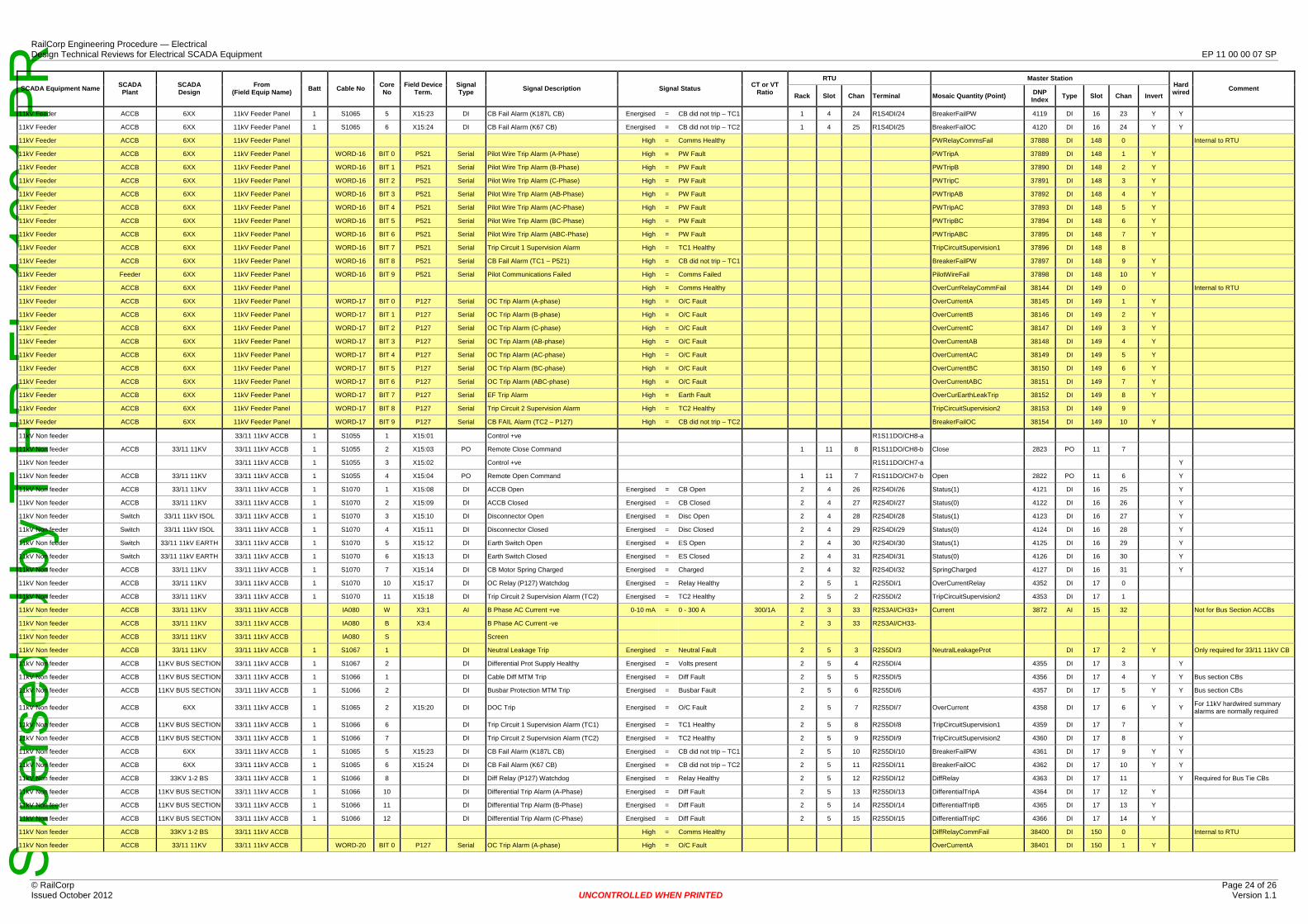
Sup
erse
ded
by T
HR
EL
1100
1 P
R
RTU Mast Stater ion SCADA SCADA From Core Field Device Signal CT or VT Hard SCADA Equipment Name Batt Cable No Signal Description Signal Status Comment Plant Design (Field Equip Name) No Term. Type Ratio DNP wired Rack Slot Chan Terminal Mo Qusaic antity (P oint) Type Slot Chan Invert Index
11kV Feeder ACCB 6XX 11kV Feeder Panel 1 S1065 5 X15:23 DI CB Fail Alarm (K187L CB) Energised = CB did not trip – TC1 1 4 24 R1S4DI/24 BreakerFailPW 411 DI9 16 23 Y Y
11kV Feeder ACCB 6XX 11kV Feeder Panel 1 S1065 6 X15:24 DI CB Fail Alarm (K67 CB) Energised = CB did not trip – TC2 1 4 25 R1S4DI/25 BreakerFailOC 412 DI0 16 24 Y Y
11kV Feeder ACCB 6XX 11kV Feeder Panel High = Comms Healthy PWRelayCommsFail 37888 DI 148 0 Internal to RTU
11kV Feeder ACCB 6XX 11kV Feeder Panel WORD-16 BIT 0 P521 Serial Pilot Wire Trip Alarm (A-Phase) High = PW Fault PWTripA 37889 DI 148 1 Y
11kV Feeder ACCB 6XX 11kV Feeder Panel WORD-16 BIT 1 P521 Serial Pilot Wire Trip Alarm (B-Phase) High = PW Fault PWTripB 37890 DI 148 2 Y
11kV Feeder ACCB 6XX 11kV Feeder Panel WORD-16 BIT 2 P521 Serial Pilot Wire Trip Alarm (C-Phase) High = PW Fault PWTripC 37891 DI 148 3 Y
11kV Feeder ACCB 6XX 11kV Feeder Panel WORD-16 BIT 3 P521 Serial Pilot Wire Trip Alarm (AB-Phase) High = PW Fault PWTripAB 37892 DI 148 4 Y
11kV Feeder ACCB 6XX 11kV Feeder Panel WORD-16 BIT 4 P521 Serial Pilot Wire Trip Alarm (AC-Phase) High = PW Fault PWTripAC 37893 DI 148 5 Y
11kV Feeder ACCB 6XX 11kV Feeder Panel WORD-16 BIT 5 P521 Serial Pilot Wire Trip Alarm (BC-Phase) High = PW Fault PWTripBC 37894 DI 148 6 Y
11kV Feeder ACCB 6XX 11kV Feeder Panel WORD-16 BIT 6 P521 Serial Pilot Wire Trip Alarm (ABC-Phase) High = PW Fault PWTripABC 37895 DI 148 7 Y
11kV Feeder ACCB 6XX 11kV Feeder Panel WORD-16 BIT 7 P521 Serial Trip Circuit 1 Supervision Alarm High = TC1 Healthy TripCircuitSupervision1 37896 DI 148 8
11kV Feeder ACCB 6XX 11kV Feeder Panel WORD-16 BIT 8 P521 Serial CB Fail Alarm (TC1 – P521) High = CB did not trip – TC1 BreakerFailPW 37897 DI 148 9 Y
11kV Feeder Feeder 6XX 11kV Feeder Panel WORD-16 BIT 9 P521 Serial Pilot Communications Failed High = Comms Failed PilotWireFail 37898 DI 148 10 Y
11kV Feeder ACCB 6XX 11kV Feeder Panel High = Comms Healthy OverCurrRelayCommFail 38144 DI 149 0 Internal to RTU
11kV Feeder ACCB 6XX 11kV Feeder Panel WORD-17 BIT 0 P127 Serial OC Trip Alarm (A-phase) High = O/C Fault OverCurrentA 38145 DI 149 1 Y
11kV Feeder ACCB 6XX 11kV Feeder Panel WORD-17 BIT 1 P127 Serial OC Trip Alarm (B-phase) High = O/C Fault OverCurrentB 38146 DI 149 2 Y
11kV Feeder ACCB 6XX 11kV Feeder Panel WORD-17 BIT 2 P127 Serial OC Trip Alarm (C-phase) High = O/C Fault OverCurrentC 38147 DI 149 3 Y
11kV Feeder ACCB 6XX 11kV Feeder Panel WORD-17 BIT 3 P127 Serial OC Trip Alarm (AB-phase) High = O/C Fault OverCurrentAB 38148 DI 149 4 Y
11kV Feeder ACCB 6XX 11kV Feeder Panel WORD-17 BIT 4 P127 Serial OC Trip Alarm (AC-phase) High = O/C Fault OverCurrentAC 38149 DI 149 5 Y
11kV Feeder ACCB 6XX 11kV Feeder Panel WORD-17 BIT 5 P127 Serial OC Trip Alarm (BC-phase) High = O/C Fault OverCurrentBC 38150 DI 149 6 Y
11kV Feeder ACCB 6XX 11kV Feeder Panel WORD-17 BIT 6 P127 Serial OC Trip Alarm (ABC-phase) High = O/C Fault OverCurrentABC 38151 DI 149 7 Y
11kV Feeder ACCB 6XX 11kV Feeder Panel WORD-17 BIT 7 P127 Serial EF Trip Alarm High = Earth Fault OverCurEarthLeakTrip 38152 DI 149 8 Y
11kV Feeder ACCB 6XX 11kV Feeder Panel WORD-17 BIT 8 P127 Serial Trip Circuit 2 Supervision Alarm High = TC2 Healthy TripCircuitSupervision2 38153 DI 149 9
11kV Feeder ACCB 6XX 11kV Feeder Panel WORD-17 BIT 9 P127 Serial CB FAIL Alarm (TC2 – P127) High = CB did not trip – TC2 BreakerFailOC 38154 DI 149 10 Y
11kV Non feeder 33/11 11kV ACCB 1 S1055 1 X15:01 Control +ve R1S11DO/CH8-a
11kV Non feeder ACCB 33/11 11KV 33/11 11kV ACCB 1 S1055 2 X15:03 PO Remote Close Command 1 11 8 R1S11DO/CH8-b Close 2823 PO 11 7
11kV Non feeder 33/11 11kV ACCB 1 S1055 3 X15:02 Control +ve R1S11DO/CH7-a Y
11kV Non feeder ACCB 33/11 11KV 33/11 11kV ACCB 1 S1055 4 X15:04 PO Remote Open Command 1 11 7 R1S11DO/CH7-b Open 2822 PO 11 6 Y
11kV Non feeder ACCB 33/11 11KV 33/11 11kV ACCB 1 S1070 1 X15:08 DI ACCB Open Energised = CB Open 2 4 26 R2S4DI/26 Status(1) 4121 DI 16 25 Y
11kV Non feeder ACCB 33/11 11KV 33/11 11kV ACCB 1 S1070 2 X15:09 DI ACCB Closed Energised = CB Closed 2 4 27 R2S4DI/27 Status(0) 412 DI2 16 Y26
11kV Non feeder Switch 33/11 11kV ISOL 33/11 11kV ACCB 1 S1070 3 X15:10 DI Disconnector Open Energised = Disc Open 2 4 28 R2S4DI/28 Status(1) 412 DI3 16 27 Y
11kV Non feeder Switch 33/11 11kV ISOL 33/11 11kV ACCB 1 S1070 4 X15:11 DI Disconnector Closed Energised = Disc Closed 2 4 29 R2S4DI/29 Status(0) 412 DI4 16 28 Y
11kV Non feeder Switch 33/11 11kV EARTH 33/11 11kV ACCB 1 S1070 5 X15:12 DI Earth Switch Open Energised = ES Open 2 4 30 R2S4DI/30 Status(1) 412 DI5 16 29 Y
11kV Non feeder Switch 33/11 11kV EARTH 33/11 11kV ACCB 1 S1070 6 X15:13 DI Earth Switch Closed Energised = ES Closed 2 4 31 R2S4DI/31 Status(0) 412 DI6 16 30 Y
11kV Non feeder ACCB 33/11 11KV 33/11 11kV ACCB 1 S1070 7 X15:14 DI CB Motor Spring Charged Energised = Charged 2 4 32 R2S4DI/32 SpringCharged 412 DI7 16 31 Y
11kV Non feeder ACCB 33/11 11KV 33/11 11kV ACCB 1 S1070 10 X15:17 DI OC Relay (P127) Watchdog Energised = Relay Healthy 2 5 1 R2S5DI/1 OverCurrentRelay 435 DI2 17 0
11kV Non feeder ACCB 33/11 11KV 33/11 11kV ACCB 1 S1070 11 X15:18 DI Trip Circuit 2 Supervision Alarm (TC2) Energised = TC2 Healthy 2 R5 2S5D2 TripCiI/2 rcuitSupervisi 435on2 DI3 17 1
11kV Non feeder ACCB 33/11 11KV 33/11 11kV ACCB IA080 W X3:1 AI B Phase AC Current +ve 0-10 mA = 0 - 300 A 300/1A 2 3 33 R2S3AI/CH33+ Current 3872 AI 15 32 Not for Bus Section ACCBs
11kV Non feeder ACCB 33/11 11KV 33/11 11kV ACCB IA080 B X3:4 B Phase AC Current -ve 2 3 33 R2S3AI/CH33-
11kV Non feeder ACCB 33/11 11KV 33/11 11kV ACCB IA080 S Screen
11kV Non feeder ACCB 33/11 11KV 33/11 11kV ACCB 1 S1067 1 DI Neutral Leakage Trip Energised = Neutral Fault 2 5 3 R2S5DI/3 NeutralLeakageProt DI 17 2 Y Only required for 33/11 11kV CB
11kV Non feeder ACCB 11KV BUS SECTION 33/11 11kV ACCB 1 S1067 2 DI Differential Prot Supply Healthy Energised = Volts present 2 5 4 R2S5DI/4 4355 DI 17 3 Y
11kV Non feeder ACCB 11KV BUS SECTION 33/11 11kV ACCB 1 S1066 1 DI Cable Diff MTM Trip Energised = Diff Fault 2 5 5 R2S5DI/5 4356 DI 17 4 Y Y Bus section CBs
11kV Non feeder ACCB 11KV BUS SECTION 33/11 11kV ACCB 1 S1066 2 DI Busbar Protection MTM Trip Energised = Busbar Fault 2 5 6 R2S5DI/6 4357 DI 17 5 Y Y Bus section CBs
For 11kV hardwired summary 11kV Non feeder ACCB 6XX 33/11 11kV ACCB 1 S1065 2 X15:20 DI DOC Trip Energised = O/C Fault 2 5 7 R2S5DI/7 OverCurrent 4358 DI 17 6 Y Y alarms are normally required
11kV Non feeder ACCB 11KV BUS SECTION 33/11 11kV ACCB 1 S1066 6 DI Trip Circuit 1 Supervision Alarm (TC1) Energised = TC1 Healthy 2 R5 2S5D8 TripCiI/8 rcuitSupervisi 435on1 DI9 17 7 Y
11kV Non feeder ACCB 11KV BUS SECTION 33/11 11kV ACCB 1 S1066 7 DI Trip Circuit 2 Supervision Alarm (TC2) Energised = TC2 Healthy 2 R5 2S5D9 TripCiI/9 rcuitSupervisi 436on2 DI0 17 8 Y
11kV Non feeder ACCB 6XX 33/11 11kV ACCB 1 S1065 5 X15:23 DI CB Fail Alarm (K187L CB) Energised = CB did not trip – TC1 2 5 10 R2S5DI/10 BreakerFailPW 436 DI1 17 9 Y Y
11kV Non feeder ACCB 6XX 33/11 11kV ACCB 1 S1065 6 X15:24 DI CB Fail Alarm (K67 CB) Energised = CB did not trip – TC2 2 5 11 R2S5DI/11 BreakerFailOC 436 DI2 17 10 Y Y
11kV Non feeder ACCB 33KV 1-2 BS 33/11 11kV ACCB 1 S1066 8 DI Diff Relay (P127) Watchdog Energised = Relay Healthy 2 5 12 R2S5DI/12 DiffRelay 4363 DI 17 11 Y Required for Bus Tie CBs
11kV Non feeder ACCB 11KV BUS SECTION 33/11 11kV ACCB 1 S1066 10 DI Differential Trip Alarm (A-Phase) Energised = Diff Fault 2 5 R13 2S5DI/13 DifferentialTripA 4364 DI 17 12 Y
11kV Non feeder ACCB 11KV BUS SECTION 33/11 11kV ACCB 1 S1066 11 DI Differential Trip Alarm (B-Phase) Energised = Diff Fault 2 5 R14 2S5DI/14 DifferentialTripB 4365 DI 17 13 Y
11kV Non feeder ACCB 11KV BUS SECTION 33/11 11kV ACCB 1 S1066 12 DI Differential Trip Alarm (C-Phase) Energised = Diff Fault 2 5 R15 2S5DI/15 DifferentialTripC 4366 DI 17 14 Y
11kV Non feeder ACCB 33KV 1-2 BS 33/11 11kV ACCB High = Comms Healthy DiffRelayCommFail 38400 DI 150 0 Internal to RTU
11kV Non feeder ACCB 33/11 11KV 33/11 11kV ACCB WORD-20 BIT 0 P127 Serial OC Trip Alarm (A-phase) High = O/C Fault OverCurrentA 38401 DI 150 1 Y
© RailCorp Page 24 of 26 Issued October 2012 UNCONTROLLED WHEN PRINTED Version 1.1
RailCorp Engineering Procedure — Electrical Design Technical Reviews for Electrical SCADA Equipment EP 11 00 00 07 SP
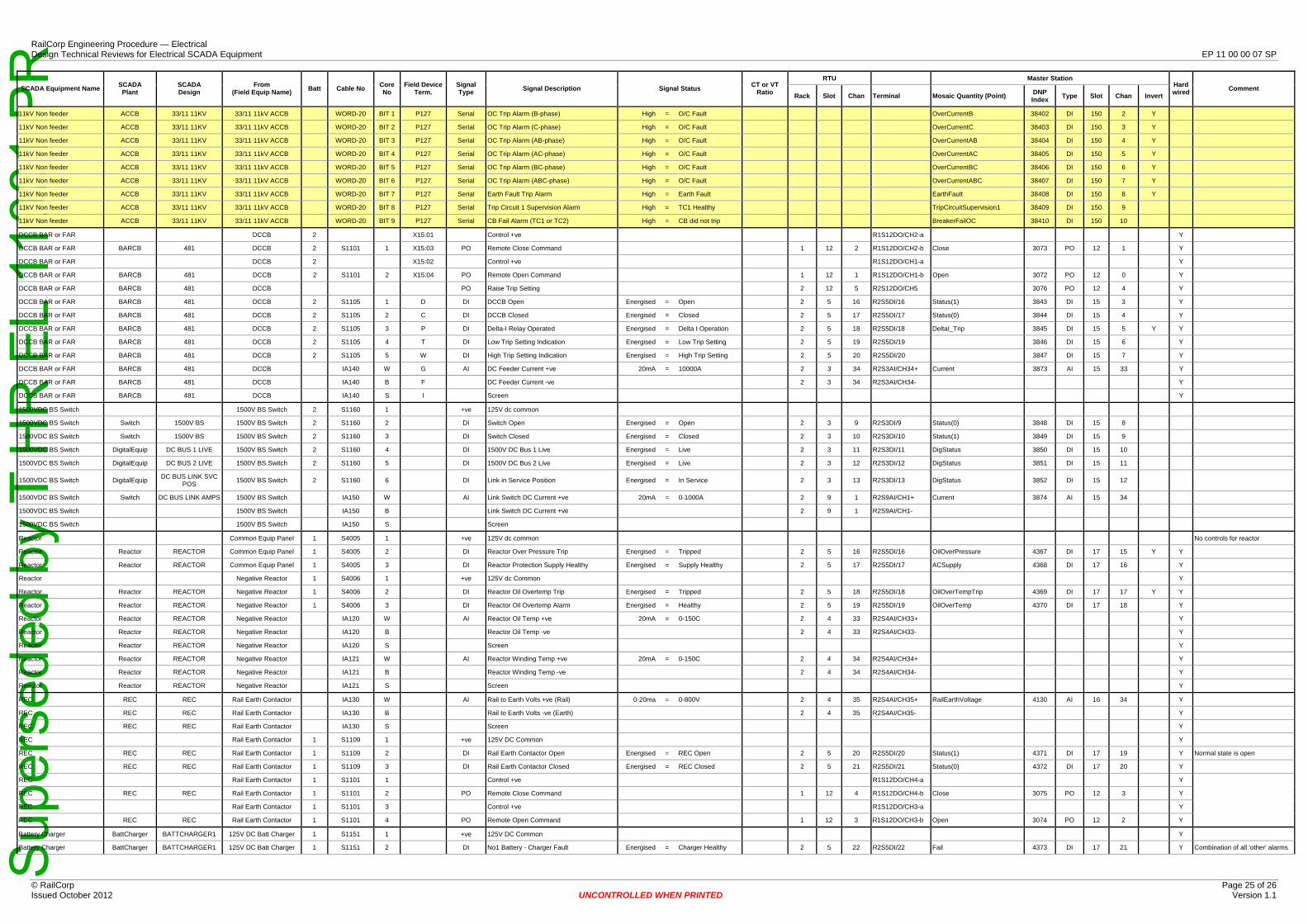
Sup
erse
ded
by T
HR
EL
1100
1 P
R
© RailCorp Page 25 of 26 Issued October 2012 UNCONTROLLED WHEN PRINTED Version 1.1
RailCorp Engineering Procedure — Electrical Design Technical Reviews for Electrical SCADA Equipment EP 11 00 00 07 SP
SCADA Equipment Name SCADA Plant
SCADA Design
From (Field Equip Name) Batt Cable No Core
No Field Device
Term. Signal Type Signal Description Signal Status CT or VT
Ratio
RTU Master Station Hard wired Comment
Rack Slot Chan Terminal Mosaic Quantity (Point) DNP Index Type Slot Chan Invert
11kV Non feeder ACCB 33/11 11KV 33/11 11kV ACCB WORD-20 BIT 1 P127 Serial OC Trip Alarm (B-phase) High = O/C Fault OverCurrentB 38402 DI 150 2 Y
11kV Non feeder ACCB 33/11 11KV 33/11 11kV ACCB WORD-20 BIT 2 P127 Serial OC Trip Alarm (C-phase) High = O/C Fault OverCurrentC 38403 DI 150 3 Y
11kV Non feeder ACCB 33/11 11KV 33/11 11kV ACCB WORD-20 BIT 3 P127 Serial OC Trip Alarm (AB-phase) High = O/C Fault OverCurrentAB 38404 DI 150 4 Y
11kV Non feeder ACCB 33/11 11KV 33/11 11kV ACCB WORD-20 BIT 4 P127 Serial OC Trip Alarm (AC-phase) High = O/C Fault OverCurrentAC 38405 DI 150 5 Y
11kV Non feeder ACCB 33/11 11KV 33/11 11kV ACCB WORD-20 BIT 5 P127 Serial OC Trip Alarm (BC-phase) High = O/C Fault OverCurrentBC 38406 DI 150 6 Y
11kV Non feeder ACCB 33/11 11KV 33/11 11kV ACCB WORD-20 BIT 6 P127 Serial OC Trip Alarm (ABC-phase) High = O/C Fault OverCurrentABC 38407 DI 150 7 Y
11kV Non feeder ACCB 33/11 11KV 33/11 11kV ACCB WORD-20 BIT 7 P127 Serial Earth Fault Trip Alarm High = Earth Fault EarthFault 38408 DI 150 8 Y
11kV Non feeder ACCB 33/11 11KV 33/11 11kV ACCB WORD-20 BIT 8 P127 Serial Trip Circuit 1 Supervision Alarm High = TC1 Healthy TripCircuitSupervision1 38409 DI 150 9
11kV Non feeder ACCB 33/11 11KV 33/11 11kV ACCB WORD-20 BIT 9 P127 Serial CB Fail Alarm (TC1 or TC2) High = CB did not trip BreakerFailOC 38410 DI 150 10
DCCB BAR or FAR DCCB 2 X15:01 Control +ve R1S12DO/CH2-a Y
DCCB BAR or FAR BARCB 481 DCCB 2 S1101 1 X15:03 PO Remote Close Command 1 12 2 R1S12DO/CH2-b Close 3073 PO 12 1 Y
DCCB BAR or FAR DCCB 2 X15:02 Control +ve R1S12DO/CH1-a Y
DCCB BAR or FAR BARCB 481 DCCB 2 S1101 2 X15:04 PO Remote Open Command 1 12 1 R1S12DO/CH1-b Open 3072 PO 12 0 Y
DCCB BAR or FAR BARCB 481 DCCB PO Raise Trip Setting 2 12 5 R2S12DO/CH5 3076 PO 12 4 Y
DCCB BAR or FAR BARCB 481 DCCB 2 S1105 1 D DI DCCB Open Energised = Open 2 5 16 R2S5DI/16 Status(1) 3843 DI 15 3 Y
DCCB BAR or FAR BARCB 481 DCCB 2 S1105 2 C DI DCCB Closed Energised = Closed 2 5 17 R2S5DI/17 Status(0) 3844 DI 15 4 Y
DCCB BAR or FAR BARCB 481 DCCB 2 S1105 3 P DI Delta-I Relay Operated Energised = Delta I Operation 2 5 18 R2S5DI/18 DeltaI_Trip 3845 DI 15 5 Y Y
DCCB BAR or FAR BARCB 481 DCCB 2 S1105 4 T DI Low Trip Setting Indication Energised = Low Trip Setting 2 5 19 R2S5DI/19 3846 DI 15 6 Y
DCCB BAR or FAR BARCB 481 DCCB 2 S1105 5 W DI High Trip Setting Indication Energised = High Trip Setting 2 5 20 R2S5DI/20 3847 DI 15 7 Y
DCCB BAR or FAR BARCB 481 DCCB IA140 W G AI DC Feeder Current +ve 20mA = 10000A 2 3 34 R2S3AI/CH34+ Current 3873 AI 15 33 Y
DCCB BAR or FAR BARCB 481 DCCB IA140 B F DC Feeder Current -ve 2 3 34 R2S3AI/CH34 Y
DCCB BAR or FAR BARCB 481 DCCB IA140 S I Screen Y
1500VDC BS Switch 1500V BS Switch 2 S1160 1 +ve 125V dc common
1500VDC BS Switch Switch 1500V BS 1500V BS Switch 2 S1160 2 DI Switch Open Energised = Open 2 3 9 R2S3DI/9 Status(0) 3848 DI 15 8
1500VDC BS Switch Switch 1500V BS 1500V BS Switch 2 S1160 3 DI Switch Closed Energised = Closed 2 3 10 R2S3DI/10 Status(1) 3849 DI 15 9
1500VDC BS Switch DigitalEquip DC BUS 1 LIVE 1500V BS Switch 2 S1160 4 DI 1500V DC Bus 1 Live Energised = Live 2 3 11 R2S3DI/11 DigStatus 3850 DI 15 10
1500VDC BS Switch DigitalEquip DC BUS 2 LIVE 1500V BS Switch 2 S1160 5 DI 1500V DC Bus 2 Live Energised = Live 2 3 12 R2S3DI/12 DigStatus 3851 DI 15 11
1500VDC BS Switch DigitalEquip DC BUS LINK SVC POS 1500V BS Switch 2 S1160 6 DI Link in Service Position Energised = In Service 2 3 13 R2S3DI/13 DigStatus 3852 DI 15 12
1500VDC BS Switch Switch DC BUS LINK AMPS 1500V BS Switch IA150 W AI Link Switch DC Current +ve 20mA = 0-1000A 2 9 1 R2S9AI/CH1+ Current 3874 AI 15 34
1500VDC BS Switch 1500V BS Switch IA150 B Link Switch DC Current +ve 2 9 1 R2S9AI/CH1
1500VDC BS Switch 1500V BS Switch IA150 S Screen
Reactor Common Equip Panel 1 S4005 1 +ve 125V dc common No controls for reactor
Reactor Reactor REACTOR Common Equip Panel 1 S4005 2 DI Reactor Over Pressure Trip Energised = Tripped 2 5 16 R2S5DI/16 OilOverPressure 4367 DI 17 15 Y Y
Reactor Reactor REACTOR Common Equip Panel 1 S4005 3 DI Reactor Protection Supply Healthy Energised = Supply Healthy 2 5 17 R2S5DI/17 ACSupply 4368 DI 17 16 Y
Reactor Negative Reactor 1 S4006 1 +ve 125V dc Common Y
Reactor Reactor REACTOR Negative Reactor 1 S4006 2 DI Reactor Oil Overtemp Trip Energised = Tripped 2 5 18 R2S5DI/18 OilOverTempTrip 4369 DI 17 17 Y Y
Reactor Reactor REACTOR Negative Reactor 1 S4006 3 DI Reactor Oil Overtemp Alarm Energised = Healthy 2 5 19 R2S5DI/19 OilOverTemp 4370 DI 17 18 Y
Reactor Reactor REACTOR Negative Reactor IA120 W AI Reactor Oil Temp +ve 20mA = 0-150C 2 4 33 R2S4AI/CH33+ Y
Reactor Reactor REACTOR Negative Reactor IA120 B Reactor Oil Temp -ve 2 4 33 R2S4AI/CH33 Y
Reactor Reactor REACTOR Negative Reactor IA120 S Screen Y
Reactor Reactor REACTOR Negative Reactor IA121 W AI Reactor Winding Temp +ve 20mA = 0-150C 2 4 34 R2S4AI/CH34+ Y
Reactor Reactor REACTOR Negative Reactor IA121 B Reactor Winding Temp -ve 2 4 34 R2S4AI/CH34 Y
Reactor Reactor REACTOR Negative Reactor IA121 S Screen Y
REC REC REC Rail Earth Contactor IA130 W AI Rail to Earth Volts +ve (Rail) 0-20ma = 0-800V 2 4 35 R2S4AI/CH35+ RailEarthVoltage 4130 AI 16 34 Y
REC REC REC Rail Earth Contactor IA130 B Rail to Earth Volts -ve (Earth) 2 4 35 R2S4AI/CH35 Y
REC REC REC Rail Earth Contactor IA130 S Screen Y
REC Rail Earth Contactor 1 S1109 1 +ve 125V DC Common Y
REC REC REC Rail Earth Contactor 1 S1109 2 DI Rail Earth Contactor Open Energised = REC Open 2 5 20 R2S5DI/20 Status(1) 4371 DI 17 19 Y Normal state is open
REC REC REC Rail Earth Contactor 1 S1109 3 DI Rail Earth Contactor Closed Energised = REC Closed 2 5 21 R2S5DI/21 Status(0) 4372 DI 17 20 Y
REC Rail Earth Contactor 1 S1101 1 Control +ve R1S12DO/CH4-a Y
REC REC REC Rail Earth Contactor 1 S1101 2 PO Remote Close Command 1 12 4 R1S12DO/CH4-b Close 3075 PO 12 3 Y
REC Rail Earth Contactor 1 S1101 3 Control +ve R1S12DO/CH3-a Y
REC REC REC Rail Earth Contactor 1 S1101 4 PO Remote Open Command 1 12 3 R1S12DO/CH3-b Open 3074 PO 12 2 Y
Battery Charger BattCharger BATTCHARGER1 125V DC Batt Charger 1 S1151 1 +ve 125V DC Common Y
Battery Charger BattCharger BATTCHARGER1 125V DC Batt Charger 1 S1151 2 DI No1 Battery - Charger Fault Energised = Charger Healthy 2 5 22 R2S5DI/22 Fail 4373 DI 17 21 Y Combination of all 'other' alarms
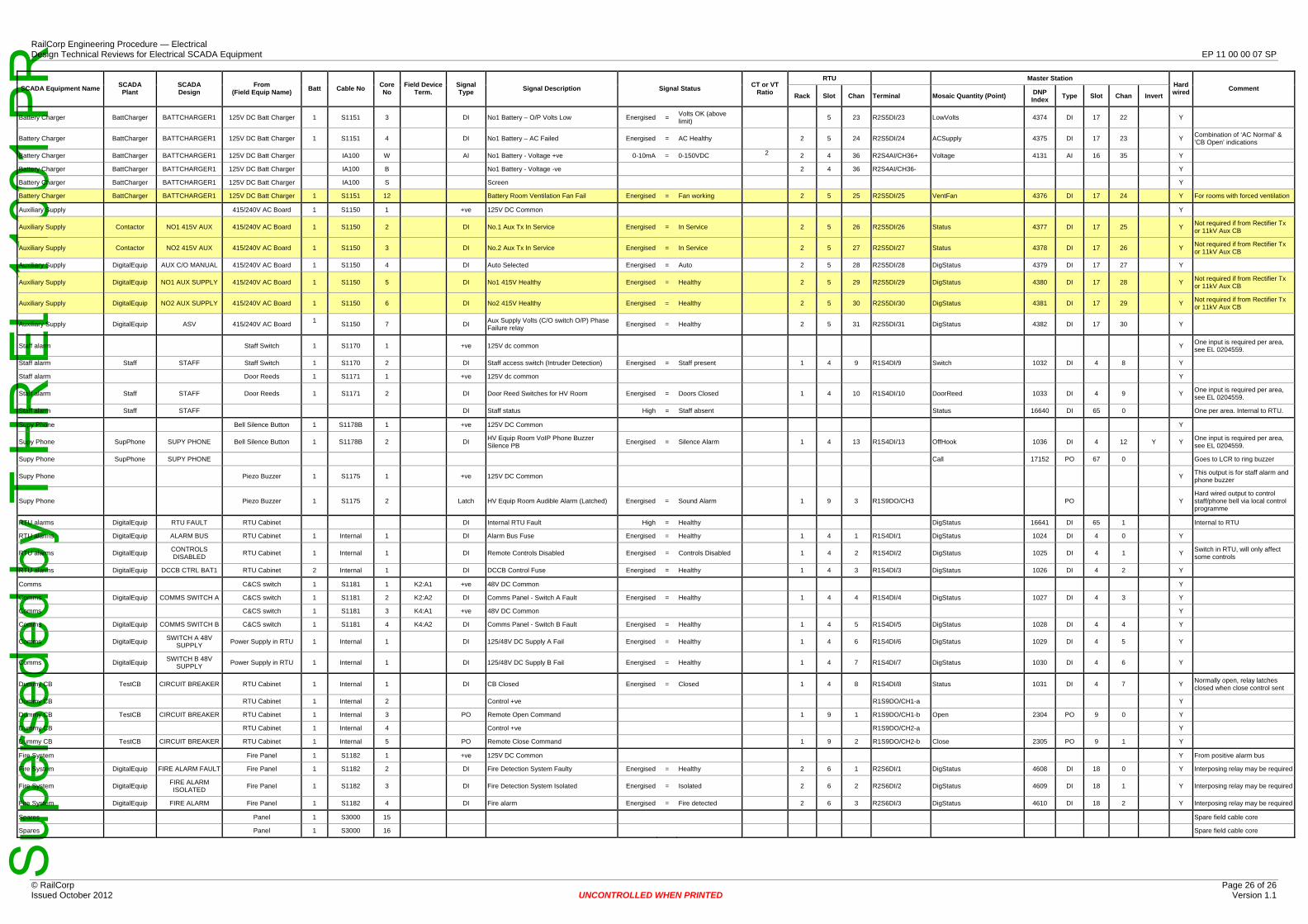
Sup
erse
ded
by T
HR
EL
1100
1 P
R
© RailCorp Page 26 of 26 Issued October 2012 UNCONTROLLED WHEN PRINTED Version 1.1
RailCorp Engineering Procedure — Electrical Design Technical Reviews for Electrical SCADA Equipment EP 11 00 00 07 SP
SCADA Equipment Name SCADA Plant
SCADA Design
From (Field Equip Name) Batt Cable No Core
No Field Device
Term. Signal Type Signal Description Signal Status CT or VT
Ratio
RTU Master Station Hard wired Comment
Rack Slot Chan Terminal Mosaic Quantity (Point) DNP Index Type Slot Chan Invert
Battery Charger BattCharger BATTCHARGER1 125V DC Batt Charger 1 S1151 3 DI No1 Battery – O/P Volts Low Energised = Volts OK (above limit)
2
5 23 R2S5DI/23 LowVolts 4374 DI 17 22 Y
Battery Charger BattCharger BATTCHARGER1 125V DC Batt Charger 1 S1151 4 DI No1 Battery – AC Failed Energised = AC Healthy 2 5 24 R2S5DI/24 ACSupply 4375 DI 17 23 Y Combination of ‘AC Normal’ & ’CB Open’ indications
Battery Charger BattCharger BATTCHARGER1 125V DC Batt Charger IA100 W AI No1 Battery - Voltage +ve 0-10mA = 0-150VDC 2 4 36 R2S4AI/CH36+ Voltage 4131 AI 16 35 Y
Battery Charger BattCharger BATTCHARGER1 125V DC Batt Charger IA100 B No1 Battery - Voltage -ve 2 4 36 R2S4AI/CH36 Y
Battery Charger BattCharger BATTCHARGER1 125V DC Batt Charger IA100 S Screen Y
Battery Charger BattCharger BATTCHARGER1 125V DC Batt Charger 1 S1151 12 Battery Room Ventilation Fan Fail Energised = Fan working 2 5 25 R2S5DI/25 VentFan 4376 DI 17 24 Y For rooms with forced ventilation
Auxiliary Supply 415/240V AC Board 1 S1150 1 +ve 125V DC Common Y
Auxiliary Supply Contactor NO1 415V AUX 415/240V AC Board 1 S1150 2 DI No.1 Aux Tx In Service Energised = In Service 2 5 26 R2S5DI/26 Status 4377 DI 17 25 Y Not required if from Rectifier Tx or 11kV Aux CB
Auxiliary Supply Contactor NO2 415V AUX 415/240V AC Board 1 S1150 3 DI No.2 Aux Tx In Service Energised = In Service 2 5 27 R2S5DI/27 Status 4378 DI 17 26 Y Not required if from Rectifier Tx or 11kV Aux CB
Auxiliary Supply DigitalEquip AUX C/O MANUAL 415/240V AC Board 1 S1150 4 DI Auto Selected Energised = Auto 2 5 28 R2S5DI/28 DigStatus 4379 DI 17 27 Y
Auxiliary Supply DigitalEquip NO1 AUX SUPPLY 415/240V AC Board 1 S1150 5 DI No1 415V Healthy Energised = Healthy 2 5 29 R2S5DI/29 DigStatus 4380 DI 17 28 Y Not required if from Rectifier Tx or 11kV Aux CB
Auxiliary Supply DigitalEquip NO2 AUX SUPPLY 415/240V AC Board 1 S1150 6 DI No2 415V Healthy Energised = Healthy 2 5 30 R2S5DI/30 DigStatus 4381 DI 17 29 Y Not required if from Rectifier Tx or 11kV Aux CB
Auxiliary Supply DigitalEquip ASV 415/240V AC Board 1 S1150 7 DI Aux Supply Volts (C/O switch O/P) Phase Failure relay Energised = Healthy 2 5 31 R2S5DI/31 DigStatus 4382 DI 17 30 Y
Staff alarm Staff Switch 1 S1170 1 +ve 125V dc common Y One input is required per area, see EL 0204559.
Staff alarm Staff STAFF Staff Switch 1 S1170 2 DI Staff access switch (Intruder Detection) Energised = Staff present 1 4 9 R1S4DI/9 Switch 1032 DI 4 8 Y
Staff alarm Door Reeds 1 S1171 1 +ve 125V dc common Y
Staff alarm Staff STAFF Door Reeds 1 S1171 2 DI Door Reed Switches for HV Room Energised = Doors Closed 1 4 10 R1S4DI/10 DoorReed 1033 DI 4 9 Y One input is required per area, see EL 0204559.
Staff alarm Staff STAFF DI Staff status High = Staff absent Status 16640 DI 65 0 One per area. Internal to RTU.
Supy Phone Bell Silence Button 1 S1178B 1 +ve 125V DC Common Y
Supy Phone SupPhone SUPY PHONE Bell Silence Button 1 S1178B 2 DI HV Equip Room VoIP Phone Buzzer Silence PB Energised = Silence Alarm 1 4 13 R1S4DI/13 OffHook 1036 DI 4 12 Y Y One input is required per area,
see EL 0204559.
Supy Phone SupPhone SUPY PHONE Call 17152 PO 67 0 Goes to LCR to ring buzzer
Supy Phone Piezo Buzzer 1 S1175 1 +ve 125V DC Common Y This output is for staff alarm and phone buzzer
Supy Phone Piezo Buzzer 1 S1175 2 Latch HV Equip Room Audible Alarm (Latched) Energised = Sound Alarm 1 9 3 R1S9DO/CH3 PO Y Hard wired output to control staff/phone bell via local control programme
RTU alarms DigitalEquip RTU FAULT RTU Cabinet DI Internal RTU Fault High = Healthy DigStatus 16641 DI 65 1 Internal to RTU
RTU alarms DigitalEquip ALARM BUS RTU Cabinet 1 Internal 1 DI Alarm Bus Fuse Energised = Healthy 1 4 1 R1S4DI/1 DigStatus 1024 DI 4 0 Y
RTU alarms DigitalEquip CONTROLS DISABLED RTU Cabinet 1 Internal 1 DI Remote Controls Disabled Energised = Controls Disabled 1 4 2 R1S4DI/2 DigStatus 1025 DI 4 1 Y Switch in RTU, will only affect
some controls
RTU alarms DigitalEquip DCCB CTRL BAT1 RTU Cabinet 2 Internal 1 DI DCCB Control Fuse Energised = Healthy 1 4 3 R1S4DI/3 DigStatus 1026 DI 4 2 Y
Comms C&CS switch 1 S1181 1 K2:A1 +ve 48V DC Common Y
Comms DigitalEquip COMMS SWITCH A C&CS switch 1 S1181 2 K2:A2 DI Comms Panel - Switch A Fault Energised = Healthy 1 4 4 R1S4DI/4 DigStatus 1027 DI 4 3 Y
Comms C&CS switch 1 S1181 3 K4:A1 +ve 48V DC Common Y
Comms DigitalEquip COMMS SWITCH B C&CS switch 1 S1181 4 K4:A2 DI Comms Panel - Switch B Fault Energised = Healthy 1 4 5 R1S4DI/5 DigStatus 1028 DI 4 4 Y
Comms DigitalEquip SWITCH A 48V SUPPLY Power Supply in RTU 1 Internal 1 DI 125/48V DC Supply A Fail Energised = Healthy 1 4 6 R1S4DI/6 DigStatus 1029 DI 4 5 Y
Comms DigitalEquip SWITCH B 48V SUPPLY Power Supply in RTU 1 Internal 1 DI 125/48V DC Supply B Fail Energised = Healthy 1 4 7 R1S4DI/7 DigStatus 1030 DI 4 6 Y
Dummy CB TestCB CIRCUIT BREAKER RTU Cabinet 1 Internal 1 DI CB Closed Energised = Closed 1 4 8 R1S4DI/8 Status 1031 DI 4 7 Y Normally open, relay latches closed when close control sent
Dummy CB RTU Cabinet 1 Internal 2 Control +ve R1S9DO/CH1-a Y
Dummy CB TestCB CIRCUIT BREAKER RTU Cabinet 1 Internal 3 PO Remote Open Command 1 9 1 R1S9DO/CH1-b Open 2304 PO 9 0 Y
Dummy CB RTU Cabinet 1 Internal 4 Control +ve R1S9DO/CH2-a Y
Dummy CB TestCB CIRCUIT BREAKER RTU Cabinet 1 Internal 5 PO Remote Close Command 1 9 2 R1S9DO/CH2-b Close 2305 PO 9 1 Y
Fire System Fire Panel 1 S1182 1 +ve 125V DC Common Y From positive alarm bus
Fire System DigitalEquip FIRE ALARM FAULT Fire Panel 1 S1182 2 DI Fire Detection System Faulty Energised = Healthy 2 6 1 R2S6DI/1 DigStatus 4608 DI 18 0 Y Interposing relay may be required
Fire System DigitalEquip FIRE ALARM ISOLATED Fire Panel 1 S1182 3 DI Fire Detection System Isolated Energised = Isolated 2 6 2 R2S6DI/2 DigStatus 4609 DI 18 1 Y Interposing relay may be required
Fire System DigitalEquip FIRE ALARM Fire Panel 1 S1182 4 DI Fire alarm Energised = Fire detected 2 6 3 R2S6DI/3 DigStatus 4610 DI 18 2 Y Interposing relay may be required
Spares Panel 1 S3000 15 Spare field cable core
Spares Panel 1 S3000 16 Spare field cable core


