URBAN ROAD DESIGN Chapter 2- Urban Road Network Planning School of Civil Engineering 4 March 2013.
Upload
vuonghuongCategory
view
228download
5
DESIGN STANDARDS
for URBAN INFRASTRUCTURE
3 ROAD DESIGN

Design Standards for Urban Infrastructure
3 ROAD DESIGN 3 ROAD DESIGN 1
3.1 General 3-1
3.2 Related codes of practice and guidelines 3-1 3.2.1 Legislation 3-1 3.2.2 Industry standards 3-1 3.2.3 Policy and guidelines 3-1
3.3 Road design 3-2 3.3.1 General design principles 3-2 3.3.2 Traffic speed 3-3 3.3.3 Sight distance 3-3 3.3.4 Elements of horizontal geometry 3-4 3.3.5 Elements of vertical geometry 3-7 3.3.6 Design form 3-9 3.3.7 Typical cross section 3-9 3.3.8 Auxiliary lanes 3-10 3.3.9 Intersections 3-10 3.3.10 Road safety 3-13
3.4 Glossary 3-13
3.5 Standard Drawings 3-18
Chapter 3 Road Design Edition 1 Issue 0

Design Standards for Urban Infrastructure
3.1 General This Chapter sets out the requirements for the design of subdivision roads, arterial roads and rural roads in the ACT.
Unless otherwise specifically stated:
• term road is used as a generic term and includes subdivision roads, arterial roads and rural roads;
• terms road and street have the same meaning and are interchangeable for the purposes of engineering design;
• term intersection refers to intersection at grade.
Issues covered in this Chapter:
• traffic speed;
• sight distance;
• horizontal alignment;
• vertical alignment;
• design form;
• typical cross section;
• auxiliary lanes;
• intersections at grade; and
• road safety audits.
3.2 Related codes of practice and guidelines 3.2.1 Legislation Australian Road Rules
3.2.2 Industry standards AS 1348:1 Road and Traffic Engineering - Glossary of Terms, Road Design and
Construction, Standards Australia.
3.2.3 Policy and guidelines Guide to Geometric Design of Rural Roads, AUSTROADS
Guide to Geometric Design of Major Urban Roads, AUSTROADS
Guide to Traffic Engineering Practice, Part 1: Traffic Flow, AUSTROADS
Guide to Traffic Engineering Practice, Part 2: Roadway Capacity, AUSTROADS
Guide to Traffic Engineering Practice, Part 5: Intersections at Grade, AUSTROADS
Guide to Traffic Engineering Practice, Part 6: Roundabouts, AUSTROADS
Guide to Traffic Engineering Practice, Part 7: Traffic Signals, AUSTROADS
Guide to Traffic Engineering Practice, Part 8: Traffic Control Devices, AUSTROADS
Chapter 3 Road Design 3-1 Edition 1 Issue 0

Design Standards for Urban Infrastructure
Guide to Traffic Engineering Practice, Part 9: Arterial Road Traffic Management, AUSTROADS
Guide to Traffic Engineering Practice, Part 10: Local Area Traffic Management, AUSTROADS
Proposed Policies for Residential Development in the ACT incorporating ACTCode, ACT Department of Urban Services, Planning and Land Management (PALM)
Road Safety Audit, AUSTROADS
3.3 Road design 3.3.1 General design principles Roads should be designed to:
• provide safe, short and fast thoroughfare and access to all road users, being motor vehicles, cyclists and pedestrians;
• clearly convey the primary function to road users and encourage appropriate driver behaviour;
• deliver traffic volumes at speeds compatible with function;
• provide convenient location for services;
• provide an opportunity for landscaping;
• allow for parking, where appropriate;
• have due regard to topography, geology, climate, environment and heritage of the site;
• provide low cost of ownership;
• comply with these Standards and relevant AUSTROADS, ACTCode and other State Road Authorities’ Guidelines and/or Standards;
The appropriate design criteria for a specific road largely depend on a set of economic indicators, namely costs of construction and operation on one side, and the financial benefits to the community on another. These are strategic parameters that influence a decision to build a road. Economic analysis, in conjunction with the traffic analysis, determine the functional class of the road and the design speed.
Guide to the Geometric Design of Major Urban Roads and Guide to the Geometric Design of Rural Roads define road classification. This classification is further refined in the ACT as follows:
• parkways (i.e. urban motorways);
• arterial roads;
• sub-arterial roads;
• collector roads; and
• access streets.
Refer to Chapter 2 Road Planning for further details.
Chapter 3 Road Design 3-2 Edition 1 Issue 0
Design Standards for Urban Infrastructure
3.3.2 Traffic speed Traditionally, design speed has been a basic parameter in determining road standards and is a function of the road classification. However, Guide to the Geometric Design of Major Urban Roads and Guide to the Geometric Design of Rural Roads have introduced an operating speed concept. Operating speed in these guidelines is defined as 85th percentile speed of cars when traffic volumes are low.
For rural roads, the methodology for the geometric design has moved to the use of “Section Operating Speed” (see Guide to the Geometric Design of Rural Roads). For major urban roads, geometric design for cars is based on the operating speed that is 10km/h higher than the legal speed limit (see Guide to the Geometric Design of Major Urban Roads). For local roads, since low standard and low design speed roads tend to return operating speeds higher than the arbitratory speed limits, operating speed is used to assess the need for traffic calming measures in suburban areas in accordance with Guide to Traffic Engineering Practice, Part 10: Local Area Traffic Management and ACTCode. See Chapter 2 Road Planning for the traffic calming measures and speed control in suburban areas.
Unless otherwise sign posted, the following general legal speed limits are in force in the ACT:
• 100km/h on parkways and rural roads;
• 80km/h on all arterial roads and some sub-arterial roads;
• 60km/h on some sub-arterial roads and major collector roads;
• 50km/h on minor collector roads and access streets.
Traditionally, access streets are designed for 40km/h (horizontal alignment) and 60km/h (vertical alignment) design speed.
Refer to Chapter 2 Road Planning for further information on the road hierarchy, traffic modelling and vehicular speed.
For the purpose of cross referencing with documents that are still based on design speed, operating speed that is determined in accordance with Guide to the Geometric Design of Major Urban Roads, Guide to the Geometric Design of Rural Roads and/or ACTcode, and design speed shall be considered to be the same.
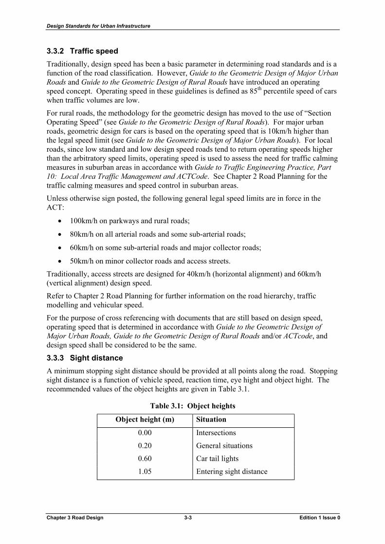
3.3.3 Sight distance A minimum stopping sight distance should be provided at all points along the road. Stopping sight distance is a function of vehicle speed, reaction time, eye hight and object hight. The recommended values of the object heights are given in Table 3.1.
Table 3.1: Object heights
Object height (m) Situation
0.00 Intersections
0.20 General situations
0.60 Car tail lights
1.05 Entering sight distance
Chapter 3 Road Design 3-3 Edition 1 Issue 0

Design Standards for Urban Infrastructure
A car driver eye height of 1.05m is used for the geometric design of both urban and rural roads.
For commercial vehicles, a driver eye height of 1.8m is used for general geometric design. A driver eye height of 2.5m is used for checking sight distances on sag curves.
For the geometric design of major urban roads, a reaction time of 2.0 seconds is to be used. For the geometric design of rural roads, a reaction time of 2.5 seconds is to be used. In situations where the adoption of a reaction time of 2.5 seconds would result in impractical solutions, a reaction time of 2.0 seconds may be considered.
Minimum values for stopping sight distance for cars and trucks are given in Guide to the Geometric Design of Major Urban Roads and Guide to the Geometric Design of Rural Roads
Overtaking sight distance (OSD), intermediate sight distance (ISD), manoeuvre sight distance (MSD), approach intersection sight distance (ASD), intersection entering sight distance (ESD) and safe intersection sight distance (SISD) are defined and discussed in detail in both Guide to the Geometric Design of Major Urban Roads and Guide to the Geometric Design of Rural Roads.
In situations where opportunities for the provision of safe sight distance might be limited, it is a good practice to show sight lines on drawings.
3.3.4 Elements of horizontal geometry 3.3.4.1 General
Horizontal alignment of a road is a basis for definition of strings of characteristic points determined from typical cross section (centreline line, edges of carriageway, edges of road formation, longitudinal drains etc) in a horizontal X-Y plane. The geometry of the road strings is made up of a series of connected curves, straights and spirals.
Physics of vehicular movement and the vehicle speed dictate selection of appropriate elements of horizontal alignment. These elements should also be aesthetically pleasing and result in cost effective solutions. Refer to Guide to the Geometric Design of Major Urban Roads and Guide to the Geometric Design of Rural Roads for further discussion on the movement on a circular path. 3.3.4.2 Horizontal alignment
Traditionally, the horizontal alignment of a road normally comprises of a series of straights and circular arcs, which may be connected by transition (spiral) curves. Recently, curvilinear horizontal alignment is frequently used in flat terrain in lieu of long straights, especially in the design of major dual carriageway roads. Curvilinear alignments are more aesthetically pleasing and blend better with environment, resulting in less ecological impact and lower construction cost. Principles for the design of a curvilinear alignment are discussed in Guide to the Geometric Design of Rural Roads.
Guide to the Geometric Design of Major Urban Roads and Guide to the Geometric Design of Rural Roads give guidelines for the length of straight as a function of speed.
Straights longer than 20Vd expressed as metres should be avoided.
Chapter 3 Road Design 3-4 Edition 1 Issue 0

Design Standards for Urban Infrastructure
The following are common types of complex horizontal curves:
• Compound curves. Compound curves comprise of two or more adjoining curves of different radii in the same direction.
• Broken back curves. Broken back curves are horizontal curves in the same direction joined by a straight.
• Reverse curves. Reverse curves are adjoining horizontal curves in opposite direction, either back-to-back or connected by a straight or spiral.
• Transition curves. Transition curves are normally used to join straights and circular curves. They provide for a comfortable transition between two elements with a different curvature and provide room for transition of crossfall to the full superelevation. The most frequently used form of transition curves is clothoid or Euler spiral. Transition curves should be omitted for sections of roads with operating speed not exceeding 60km/h.
Guidelines for use of the above complex horizontal curves in the horizontal alignment design are discussed in Guide to the Geometric Design of Major Urban Roads and Guide to the Geometric Design of Rural Roads in more detail.
Formula for calculation of the radius of horizontal curve is given in both Guide to the Geometric Design of Major Urban Roads and Guide to the Geometric Design of Rural Roads.
Minimum radii of horizontal curves, maximum superelevation and maximum friction demand for a range of operating speeds are tabulated in Guide to the Geometric Design of Major Urban Roads and Guide to the Geometric Design of Rural Roads.
The minimum curve length is required to provide satisfactory appearance and avoid kinks in the horizontal alignment.
On curves with radii less than 200m, lane widening is required in order to accommodate standard design vehicle (ie 19m long semi trailer). Where the required lane widening on a curve is greater than 4.6m, cars have a tendency to travel two abreast. Thus, the full pavement should be constructed across the 4.6m width, with the constant line width (normally 3.5m) line-marked around the curve.
Small radius curves shall be checked against the sight distance requirements, since the sight distance may be limited by close proximity of lateral obstructions such as cut batters, vegetation, bridge piers and signs. If required, benching shall be provided on the inside of the curve in accordance with Guide to the Geometric Design of Rural Roads. For clearances to roadside objects refer to Chapter 11 Guardrails, Fences and Barriers. 3.3.4.3 Superelevation
Superelevation is introduced to help vehicles to negotiate circular path by reducing friction demand. Superelevation also provides driver guidance into the curve. In general:
• urban roads with design speeds of up to and including 60km/h shall not be superelevated;
• urban roads with design speeds between 60km/h and 80km/h and rural roads with design speeds up to 60km/h should be superelevated, if superelevation does not encourage speeding;
Chapter 3 Road Design 3-5 Edition 1 Issue 0

Design Standards for Urban Infrastructure
• urban roads with design speeds in excess of 80km/h and rural roads with design speed in excess of 60km/h shall be superelevated.
Maximum values of superelevation shall be in accordance with Table 3.2.
Table 3.2 Maximum values of superelevation as a function of operating speed
Road type Operating speed
(km/h)
Maximum recommended superelevation
(%)
Absolute maximum superelevation
(%)
Urban = 60km/h No superelevation No superelevation
= 60km/h
= 80km/h
4% 6%
> 80km/h 5% 7%
Rural = 60km/h 5% 7%
> 60km/h 7% 10%
Generally:
• The minimum radii of horizontal curves and the absolute maximum values of superelevation should be avoided, especially on urban roads.
• The designer should note that the minimum radius of horizontal curve corresponds with the maximum superelevation adopted for the operating speed. By selecting different values for the superelevation and/or operating speed, the designer has an opportunity to provide driving comfort commensurate with the intended road function.
• All rural roads, regardless of the operating (design) speed should be superelevated.
• Adverse crossfall on urban roads with operating speed above 60km/h are acceptable provided that the requirements of the Guide to the Geometric Design of Major Urban Roads are met.
• Change of superelevation on bridges should be avoided.
Guide to the Geometric Design of Major Urban Roads and Guide to the Geometric Design of Rural Roads provide further considerations regarding the application of superelevation.
Ideally, a person driving at operating speed should experience the same centripetal acceleration in every curve, including the minimum radius curve. Therefore, every curve on a given section of the road with a constant operating speed should be superelevated so that proportions of centripetal force due to superelevation and side friction are the same as for the minimum radius curve. This indicates that the required superelevation in a particular curve is proportional to maximum superelevation, maximum side friction factor and minimum radius of horizontal curve adopted for the operating speed of the road section.
Guide to the Geometric Design of Major Urban Roads and Guide to the Geometric Design of Rural Roads discuss this concept in detail.
Chapter 3 Road Design 3-6 Edition 1 Issue 0

Design Standards for Urban Infrastructure
3.3.4.4 Superelevation development and length of transition
Superelevation development is the pavement rotation from normal crossfall to the full superelevation required for the particular curve. Full superelevation should be developed at both ends of the circular arc. The adopted position of the axis of the pavement rotation depends on the type of road, typical cross section, terrain, location of the road and surface drainage requirements. Normally:
• On a two lane two way road the axis of rotation is centreline of the road and both halves of the cross section (including shoulders) are rotated independently.
• On a two lane dual carriageway road the axis of rotation is the median edge of the pavement.
• On three lane dual carriageway road the axis of rotation is between the centre lane and the median lane.
• On interchange ramps the axis of rotation is the pavement edge.
The length of superelevation development is the distance required for the pavement to change its crossfall from normal to superelevated, at the same time providing riding comfort and satisfactory appearance. Thus, two criteria are used to determine this length:
• Rate of rotation; and
• Relative grade, ie the difference between the longitudinal grade of the edge of the carriageway and the longitudinal grade of the axis of rotation.
For circular arcs with transition (spiral) curves, it is a common practice to adopt the length of the superelevation development equal to the length of the transition curve.
At reverse curves with common tangent points, zero pavement crossfall is unavoidable at the common point. This should not be coincidental with zero longitudinal grade.
Extreme care shall be taken in the vicinity of zero crossfall. The designer is to check drainage and provide adequate longitudinal grade to ensure that water is not ponding on the pavement. The subgrade superelevation shall be treated as shown in the Standard Drawing. Refer to Chapter 1 Stormwater for drainage details.
Refer to Guide to the Geometric Design of Major Urban Roads and Guide to the Geometric Design of Rural Roads for detail requirements. Refer to ACTCode for the requirements for the design of residential roads.
3.3.5 Elements of vertical geometry 3.3.5.1 General principles
Vertical alignments are designed with respect to sight distances, which in turn are a function of speed.
As an absolute minimum, a safe stopping sight distance must be provided at every point on the vertical alignment.
Chapter 3 Road Design 3-7 Edition 1 Issue 0

Design Standards for Urban Infrastructure
Typical controls for the vertical geometry, in no specific order, are:
• topology;
• geology;
• existing intersections;
• property accesses and driveways;
• required clearances for structures;
• required clearances for services; and
• pedestrian and cycling requirements.
In addition to checking for the required minimum lateral clearance, overpasses and large trees should be checked for truck sight stopping distance. For this purpose, driver eye height shall be set to 2.5m and the target height to 0.6m (tail lights of the vehicle in front). 3.3.5.2 Grades
The minimum grade is a function of road drainage. On rural roads, in cuttings and at the superelevation transitions, grades should be adequate for at least table drains or gutters, ie minimum 0.5% to 1.0%. In fill and outside the superelevation transitions, unkerbed roads could have 0% grade providing that table drains have positive gradient.
On all kerbed roads in the ACT, the desirable minimum grade shall be 1.0%. Flatter grades (between 0.5% and 1.0%) may be permitted subject to the designer providing satisfactory evidence that drainage provision and the proposed construction practices are such that no ponding shall occur. Grades flatter that 0.5% may be permitted only in exceptional circumstances (ie widening of existing pavement). The designer shall outline procedures that will ensure that the finished gutter profile and pavement surface are free draining and that the width of flow is within the requirements.
Unkerbed roads may be provided as the first stage of kerbed roads. To minimise abortive work and maximise utilisation of the most expensive single road component (the pavement), it is a good practice to adopt grades as required for the kerbed roads.
The maximum grade is a function of site conditions, vehicle dynamics, road construction cost and maintenance cost. Depending on the design speed and terrain, maximum grades vary from 3% to 10% and more.
The minimum length of grade is governed by appearance. The maximum length of grade, especially steep grade, is governed by the operating speed of a typical loaded truck (uphill) and the risk of brake failure (downhill).
Guide to the Geometric Design of Major Urban Roads, Guide to the Geometric Design of Rural Roads and ACTCode provide adequate information to adopt the correct maximum grade and the length of grade for the operating conditions of the road. 3.3.5.3 Vertical curves
Vertical curves are used to provide transition between different grades and increase sight distance across the two grades.
The most common form of the vertical curve is a parabola, which is an approximation of a circular curve (see Guide to the Geometric Design of Rural Roads).
Chapter 3 Road Design 3-8 Edition 1 Issue 0

Design Standards for Urban Infrastructure
Convex vertical curves are referred to as crest or summit curves. Concave vertical curves are commonly known as sag curves.
Three criteria are used to determine the length of a vertical curve:
• sight distance, usually sight stopping distance;
• appearance; and
• comfort, ie vertical acceleration.
In case of crest curves, the third (comfort) criterion is met if the sight distance and appearance criteria are met. However, on low speed suburban roads, meeting the appearance criterion may not be possible. In such cases, the length of the vertical curve adopted from the sight distance criterion should be also checked for comfort.
In case of sag curves, appearance and comfort are normally the governing criteria. Sight distance is checked for overhead obstructions (if present) and/or for headlight sight distance (for operating speeds above 80km/h).
Contrary to the horizontal curves, reverse vertical curves with common tangent points are acceptable.
The designer should check the resulting grade from superimposing superelevation and longitudinal grade for drainage considerations. Some combination of long transitions and steep grades result in sheet flows along the road and slow evacuation of the surface water across the road. Refer to Chapter 1 Stormwater for detail requirements.
3.3.6 Design form Horizontal and vertical alignments should be in tune with each other. Good three dimensional co-ordination of the horizontal and vertical alignment of a road improves traffic safety and aesthetics.
Careful consideration is needed when deciding on the initial position of the alignment. Incorrect selection of the alignment results in high cost of the road.
The operating speed in both horizontal and vertical projections should be the same or, as a minimum, of the same order. However, the combination of minimum elements of plan and profile should be avoided, as it is likely to produce an unsatisfactory solution.
Where adopted, minimum sight distances shall be checked three dimensionally.
The designer should remember that the combined road alignment must be safe for all users in all conditions.
Refer to Guide to the Geometric Design of Major Urban Roads and Guide to the Geometric Design of Rural Roads for further discussion.
3.3.7 Typical cross section The typical cross section defines the relationships between functional elements of the road. It defines origin points of lines (strings) that will be created in the other two projections (plan and profile).
Selection of elements of a cross section is an iterative process based on road function, safety environmental constraints, aesthetics and available funding. All design elements of the cross section must have proper crossfall to efficiently evacuate surface water away from the road formation. Subsoil (pavement) drainage is discussed in Chapter 6 Road Pavements.
Chapter 3 Road Design 3-9 Edition 1 Issue 0

Design Standards for Urban Infrastructure
The width of a kerbed road is measured from the face of the kerb. Normal lane width is 3.5m. Typical widths and normal crossfall of cross sections of urban roads above and including internal roads are given in Guide to the Geometric Design of Major Urban Roads. Typical widths and normal crossfall of cross section of urban road up to and including collector roads are given in ACTCode. See Chapter 13 Pedestrian and Cycling Facilities for the provision for on road cycling.
The designer should note that there are some benefits, particularly in narrow access streets, in using one way crossfalls. Overland drainage flows should be checked in roads with one way crossfalls as the overall capacity of the road to transfer flows is significantly reduced over the two way crossfall configuration. Refer to Chapter 1 Stormwater for requirements.
Kerbs are normally provided on urban roads with speed limits up to and including 80km/h. Details of the kerbs normally used in the ACT are given in the Standard Drawings.
In the areas adjacent to open space where parking is to be discouraged, kerb only or kerb and gutter should be used. Refer to Standard Drawings for typical use of specific kerb types.
Even on unkerbed urban roads, intersections should be kerbed in order to:
• better channel the traffic;
• provide protection for pedestrians and off road cyclists crossing the road; and
• allow protection for the traffic signals and signs.
Careful treatment of on road cycling provisions is required at all intersections, especially in cases when mid block unkerbed roads with on shoulder cycling are approaching kerbed intersections. Refer to Chapter 13 Pedestrian and Cycling Facilities.
If construction of a dual carriageway road (usually a 80km/h+ arterial road) is staged, the width of the first stage carriageway shall be 9.0m. During the first stage of operation, a 4.5m wide shared lane shall be provided in each direction. When the road is duplicated, the existing carriageway shall be line-marked with two 3.5m wide traffic lanes and 2.0m wide cycle lane. The minimum width of the second carriageway shall be 9.0m to allow for the same lane configuration.
The first stage carriageway should have mountable kerbs on both sides to allow for broken down vehicles to be pushed on the verge. The second carriageway should typically have barrier kerb on the verge side and mountable kerb on the median side.
For the widths of median , refer to Guide to the Geometric Design of Major Urban Roads.
For landscaping in verges see Chapter 22 Soft Landscaping Design.
For the lighting design requirements and lateral position of light poles refer to Chapter 12 Public Lighting.
3.3.8 Auxiliary lanes Refer to and Guide to the Geometric Design of Rural Roads for further discussion.
3.3.9 Intersections 3.3.9.1 Types and control
Two major intersection types are grade separated intersections (interchanges) and intersections at grade. Interchanges are not covered specifically in these Standards since they are rare in the ACT.
Chapter 3 Road Design 3-10 Edition 1 Issue 0

Design Standards for Urban Infrastructure
The fundamental design considerations related to intersections at grade are summarised in this section. Detailed information is provided in Guide to Traffic Engineering Practice – Part 5 – Intersections at Grade, Guide to Traffic Engineering Practice – Part 6 – Roundabouts, Guide to the Geometric Design of Major Urban Roads and Guide to the Geometric Design of Rural Roads. Refer also to Chapter 2 Road Planning and to Chapter 13 Pedestrian and Cycling Facilities.
Basic geometric intersection forms are:
• three leg intersection (‘T’ intersection);
• four way intersection (cross intersection); and
• multi leg intersection.
Multi leg intersections should be avoided.
Intersection treatments may be:
• plain;
• flared; and
• channelled, including roundabouts.
Plain intersections are the most common type where continuation of the linemarking provides traffic channelling. The designer shall design the left turn to satisfy turning requirements for an adopted design vehicle.
Flared intersections have one or more approaches which are widened to accommodate additional turning lanes. Traffic channelling is provided by linemarking.
Channelled intersections have physical traffic islands which are used to direct traffic into clearly defined paths, thus minimising undesirable and dangerous movements, and increasing safety and capacity. A roundabout is considered to be a special form of a channelled intersection.
Intersection control may be:
• priority control (“Give way” or “Stop”); and
• signalised.
Refer to Chapter 9 Traffic Control Drawings for details regarding signage, linemarking and traffic signals.
Geometric type, treatment and intersection control on major roads should be modelled using SIDRA. SIDRA modelling is usually not required in suburban design. 3.3.9.2 Traffic manoeuvres at intersections
Basic types of manoeuvres at intersections are:
• crossing;
• diverging;
• merging; and
• weaving.
Multiple manoeuvres should be avoided as they are confusing and usually lead to capacity and safety problems.
Chapter 3 Road Design 3-11 Edition 1 Issue 0

Design Standards for Urban Infrastructure
Assuming that all legitimate traffic movements are possible at the intersection, the number of conflict points is calculated as
!n
where
n number of incoming legs.
Thus, for a three leg intersection, the number of conflict points is:
6321!3 =××= .
For a four leg intersection, the number of conflict points is:
244321!4 =×××= ,
and for a five leg intersection:
12054321!5 =××××= .
This clearly indicates why priority controlled ‘T’ intersections are preferred. 3.3.9.3 Intersection positioning and spacing
Intersection positioning and spacing is usually governed by road planning and urban planning. Refer to Chapter 2 Road Planning.
Generally, intersections in major roads should be positioned:
• in or near horizontal curves of large radii;
• on the outside of horizontal curves;
• close to the middle of tangent straights;
• in sags;
• away from objects like bridges and underpasses; and
• away from any constraints that might impact on a future capacity upgrade.
Intersections should not be positioned:
• in or near horizontal curves of small radii;
• on the inside of horizontal curves;
• in curves with superelevation greater than 3%;
• within the area of superelevation development; and
• on or close to sharp crests.
Similar guidelines should be followed in the design of subdivision intersections. 3.3.9.4 Intersection layout
Once the geometric intersection form, treatment and type of control have been adopted in accordance with Chapter 2 Road Planning, detail intersection layout shall be designed in accordance with Guide to Traffic Engineering Practice – Part 5 – Intersections at Grade and Guide to Traffic Engineering Practice – Part 6 – Roundabouts as appropriate. The designers are reminded that the sight distances given in these Guides are calculated for 1.15m eye height and should be recalculated for the 1.05m eye height as per these standards.
Chapter 3 Road Design 3-12 Edition 1 Issue 0

Design Standards for Urban Infrastructure
All turning manoeuvres should be checked for compliances with the swept path of the design vehicle either using standard templates or, preferably, using computer software such as AutoTURN. 3.3.9.5 Alignments of the incoming legs
Guide to Traffic Engineering Practice – Part 5 – Intersections at Grade, Guide to Traffic Engineering Practice – Part 6 – Roundabouts, Guide to the Geometric Design of Major Urban Roads and Guide to the Geometric Design of Rural Roads provide information about acceptable treatments of the alignments of the incoming legs.
The incoming alignments should be of the highest possible standard. Major movements should have operating speeds consistent with the adjoining mid block sections.
Normally, the grade of the major road should be carried through the intersection unmodified. The exception is an intersection located on a steep grade, where the steep grade needs to be flattened to minimise a risk of overturning of high vehicles when travelling on adverse cross fall. This is especially important at roundabouts.
It is a good practice to locate an intersection on a maximum 3% to 4% grade. If a roundabout is located on a grade steeper than 4%, the designer should demonstrate that the resulting crossfall of the circulating lanes of the roundabout provides sufficient stability for high vehicles.
3.3.10 Road safety Some official estimates indicate that around 30% of crashes relate to the roadside environment. This figure is probably underestimated since the roadside environment figures in many speed related crashes.)
Refer to Guide to the Geometric Design of Major Urban Roads and Guide to the Geometric Design of Rural Roads for detail discussion on the road safety principles and practice. Refer also to Chapter 9 Traffic Control Devices, Chapter 11 Guardrails, Fences and Barriers, Chapter 12 Public Lighting, Chapter 13 Pedestrian and Cycling Facilities and Chapter 22 Soft Landscape Design for further safety requirements.
Currently, there is no policy on road safety audits of new projects in the ACT. The Client should decide on a project to project basis if a formal road safety audit in accordance with Road Safety Audit is required, and appoint an independent auditor to conduct the audit.
3.4 Glossary Adverse Crossfall: A slope on a curved pavement which generates forces detracting from the
ability of a vehicle to maintain a circular path.
Alignment: The geometric form of the centreline (or other reference line) of a carriageway in both the horizontal and vertical directions.
Arterial Road: A road with a prime function to provide for major regional and inter-regional traffic movements.
Auxiliary Lane: A portion of the carriageway adjoining the through traffic lanes, used for purposes supplementary to the through traffic movement.
Barrier: An obstruction placed to prevent vehicle access to a particular area.
Barrier Kerb: A kerb with a profile and height sufficient to prevent or discourage vehicles moving off the carriageway.
Chapter 3 Road Design 3-13 Edition 1 Issue 0

Design Standards for Urban Infrastructure
Carriageway: That portion of a road or bridge devoted particularly to the use of vehicles, inclusive of the shoulders and auxiliary lanes.
Centreline: The basic line which defines the axis or alignment of the centre of a road or other works.
Clearance: The space between a moving and a stationary object.
Crossfall: The slope, measured at right angles to the alignment, of the surface any part of a carriageway.
Crown: The highest point on the cross section of a carriageway with two-way crossfall.
Cycle Lane: A paved area adjacent to and flush with the traffic lane pavement for the movement of cyclists.
Design Speed: A minimal speed fixed to determine the geometric features of a road.
Design Vehicle: A hypothetical road vehicle whose mass, dimensions and operating characteristics are used to determine geometric requirements.
Drainage: Natural or artificial means for the interception and removal of surface of subsurface water.
Footpath: A public way reserved for the movement of pedestrians and manually propelled vehicles.
Formation: The surface of the finished earthworks, excluding cut or fill batters.
Grade: A length of carriageway sloping longitudinally.
The rate of longitudinal rise (or fall) of a carriageway with respect to the horizontal, expressed as a percentage.
To design the longitudinal profile of a road.
To secure a predetermined level or inclination to a road or other surface.
To shape or smooth an earth, gravel, or other surface by means of a grader of similar implement.
To mix aggregates according to a particle size distribution.
Grade Separation: The separation of road, rail or other traffic so that crossing movements, which would otherwise conflict, are at different elevations.
Horizontal Curve: A curve in the plan or horizontal alignment of a carriageway.
Interchange: A grade separation of two or more roads with one or more interconnecting carriageways.
Intermediate Sight Distance: A distance, adopted for reasons of economy, which models an overtaking vehicle completing, or aborting, an overtaking manoeuvre before reaching an opposing vehicle.
Intersection: A place at which two or more roads at grade or with grade separation.
Intersection Angle: An angle between two successive straights on the centreline of a carriageway.
The angles between the centrelines of two intersecting carriageways.
Intersection (at-grade): An intersection where carriageways cross at a common level.
Chapter 3 Road Design 3-14 Edition 1 Issue 0

Design Standards for Urban Infrastructure
Intersection Leg: Any one of the carriageways radiating from and forming part of an intersection.
K Value: The constant rate of change of grade of a parabolic vertical curve expressed as a percentage.
Kerb: A raised border of rigid material formed at the edge of a carriageway.
Kerb Clearances: A distance by which the kerb should be set back in order to maintain the maximum capacity of the traffic lane.
Lane (Traffic): A portion of the paved carriageway marked out by kerbs, painted line or barriers, which carries a single line of vehicles in one constant direction.
Lane Separator: A separator provided between lanes carrying traffic in the same direction to discourage or prevent lane changing, or to separate a portion of a speed change lane from through lanes.
Lateral Friction: The force which, when generated between the tyre and the road surface assists a vehicle to maintain a circular path.
Level of Service (LOS): A qualitative measure describing operational conditions within a traffic stream and their perception by motorists and passengers.
Line of Sight: The direct line of uninterrupted view between a driver and an object specified height above the carriageway in the lane of travel.
Longitudinal Friction Factor: The friction between vehicle tyres and the road pavement measured in the longitudinal direction.
Longitudinal Section: A vertical section, usually with an exaggerated vertical scale, showing the existing and design levels along a road design line, or another specified line.
Median: A strip of road, not normally intended for use by traffic, which separates carriageways for traffic in opposite directions.
Median Island: A short length of median serving a localised purpose in an otherwise undivided road.
Median Opening: A gap in a median provided for crossing and turning traffic.
Normal Cross Section: The cross section of the carriageway where it is not affected by superelevation or widening.
One-way Road: A road or street on which all vehicular traffic travels in the same direction.
Overtaking: The manoeuvre I which a vehicle moves from a position behind to a position in front of another vehicle travelling in the same direction.
Overtaking Distance: The distance required for one vehicle to overtake another vehicle.
Pavement: That portion of a road designed for the support of, and to form the running surface for, vehicular traffic.
Property Line: The boundary between a road reserve and the adjacent land.
Rate of Rotation: The rate of rotation required to achieve a suitable distance to uniformly rotate the crossfall from normal to full superelevation. The usual value adopted is 0.025 rad/sec; 0.035 rad / sec is the maximum value.
Reaction Distance: The distance travelled during the reaction time.
Chapter 3 Road Design 3-15 Edition 1 Issue 0

Design Standards for Urban Infrastructure
Reaction Time: The time between the driver’s reception of stimulus and taking appropriate action.
Re-alignment: An alteration to the control line of a road which may affect only its vertical alignment but, more usually, alters its horizontal alignment.
Reverse Curve: A section of road alignment consisting of two arcs curing in opposite directions and having a common tangent point or being joined by short transition curve.
Road(way): A route trafficable by motor vehicles; in law, the public right-of-way between boundaries of adjoining property.
Roundabout: An intersection where all traffic travels in one direction around a central island.
Rural road: Normally a sealed unkerbed road with free draining pavement and table drains instead of gutters. In urban areas, rural type roads may be provided where there is no adjacent urban development. The term rural road does not imply “low standard” road or “short life” road. If such requirements exist, they are explicitly specified by the Client.
Sag Curve: A concave vertical curve in the longitudinal profile of a road.
Shoulder: The portion of formed carriageway that is adjacent to the traffic lane and flush with the surface of the pavement.
Sideways Friction Co-efficient: The ratio of the resistance to side ways motion of the tyre of a vehicle (on a specified pavement) and the normal force on that wheel due to the vehicle mass.
Sight Distance: Approach Sight Distance
The distance required for a driver to perceive marking or hazards on the road surface and to stop.
Car Stopping Distance
The distance required for a car driver to perceive an object on the road and to stop before striking it.
Entering Sight Distance (ESD)
The sight distance required for minor road drivers to enter a major road via a left or right turn, such that traffic on the road is unimpeded.
Manoeuvre Sight Distance
The distance required for an alert car driver to perceive an object on the road and to take evasive action.
Overtaking Sight Distance
The sight distance required for a driver to initiate and safely complete an overtaking manoeuvre.
Railway Crossing Sight Triangle
The clear area required for a truck driver to perceive a train approaching an uncontrolled railway crossing and to stop the truck.
Chapter 3 Road Design 3-16 Edition 1 Issue 0

Design Standards for Urban Infrastructure
Safe Intersection Sight Distance
The distance required for a driver in a major road to observe a vehicle entering from a side road, and to stop before colliding with it.
Sight Distance Through Underpass
The distance required for a truck driver to see beneath a bridge located across the main road, to perceive any hazard on the road ahead, and to stop.
Truck Stopping Sight Distance
The distance required for a truck driver to perceive an object on the road and to stop before striking it.
Skid Resistance: The frictional relationship between a pavement surface and vehicle tyres during braking or cornering manoeuvres. Normally measured of wet surfaces, it varies with the speed and the value of ‘slip’ adopted.
Slope: The inclination of a surface with respect to the horizontal, expressed as rise or fall in a certain longitudinal distance.
An inclined surface.
Speed: 85th Percentile
The speed at which 85 percent of car drivers will travel slower and 1 percent will travel faster.
Operating Speed of Trucks
The 85th percentile speed of trucks measured at a time when traffic volumes are low.
Section Operating Speed
The value at which vehicle speeds on a series of curves tend to stabilise, and is related to the range of radii on the curves.
Stopping Sight Distance: The sight distance required by an average driver, travelling at a give speed, to react and stop.
Sub-arterial Road: Road connecting arterial roads to areas of development, and carrying traffic directly from on part of a region to another.
Superelevation: A slope on a curved pavement selected so as to enhance forces assisting a vehicle to maintain a circular path.
Superelevation Development: The area in which the transverse slopes on a carriageway are gradually changed from normal crossfall to superelevation.
Table Drain: The side drain of a road adjacent to the shoulder, having its invert lower than the pavement base and being part of the formation.
Terrain: Topography of the land.
Traffic: A generic term covering all vehicles, people, and animals using a road.
Traffic Island: A defined area, usually at an intersection, from which vehicular traffic is excluded. It is used to control vehicular movements and as a pedestrian refuge.
Traffic Lane: A portion of the paved carriageway marked out by kerbs, painted line or barriers, which carries a single line of vehicles in one constant direction.
Chapter 3 Road Design 3-17 Edition 1 Issue 0

Design Standards for Urban Infrastructure
Traffic Sign: A sign to regulate traffic and warn or guide drivers.
Transition Curve: A curve of varying radius used to model the path of a vehicle as the driver moves the steering wheel from straight to a horizontal curve of constant radius.
Typical Cross Section: A cross section of a carriageway showing typical dimensional details, furniture locations and features of the pavement construction.
Verge: That portion of the formation not covered by the carriageway or footpath.
Vertical Alignment: The longitudinal profile along the centreline of a road.
Vertical Curve: A curve (generally parabolic) in the longitude profile of a carriageway to provide for a change of grade at a specified vertical acceleration.
3.5 Standard Drawings Title Drawing
Number Kerb and Gutter Standard Details Sheet 1 DS3-01
Kerb and Gutter Standard Details Sheet 2 DS3-02
Chapter 3 Road Design 3-18 Edition 1 Issue 0