Design Specifications for Product To Estimate … Research Note 88-112 Design Specifications for...
141
ARI Research Note 88-112 Design Specifications for Product To Estimate Manpower Requirements of System Designs !.) Eleanor Criswell, Rob Williford, and Mike Smith Science Applications International Corp. 0 for Contracting Officer's Representative Christine R. Hartel Manned Systems Group John F. Hayes, Chief Systems Research Laboratory Robin L. Keesee, Director September1988 DTIC S ELECTE - MAY 0 4 1989 D E United States Army Research Institute for the Behavioral and Social Sciences Approved fur public release; distribution unlimited
Transcript of Design Specifications for Product To Estimate … Research Note 88-112 Design Specifications for...
ARI Research Note 88-112
Design Specifications for ProductTo Estimate Manpower Requirements
of System Designs!.) Eleanor Criswell, Rob Williford, and Mike Smith
Science Applications International Corp.0
for
Contracting Officer's RepresentativeChristine R. Hartel
Manned Systems GroupJohn F. Hayes, Chief
Systems Research LaboratoryRobin L. Keesee, Director
September1988 DTICS ELECTE -
MAY 0 4 1989 DE
United States ArmyResearch Institute for the Behavioral and Social Sciences
Approved fur public release; distribution unlimited
U.S. ARMY RESEARCH INSTITUTEFOR THE BEHAVIORAL AND SOCIAL SCIENCES
A Field Operating Agency Under the Jurisdictionof the Deputy Chief of Staff for Personnel
EDGAR M. JOHNSON JON W. BLADESTechnical Director COL, IN
Commanding
Research accomplished under contractfor the Department of the Army
Applied Science Associates, Inc.
Technical review by
Jonathan KaplanJohn E. Stewart
NOTICES
DISTRIBUTION: This report has been cleared for release to the Defense Technical InformationCenter (DTIC) to comply with regulatory requirements. It has been given no primary distributionother than to DTIC and will be available only through DTIC or the National TechnicalInformation Service (NTIS).
FINAL DISPOSITION: This report may be destroyed when it is no longer needed. Please do notreturn it to the U.S. Army Research Institute for the Behavioral and Social Sciences.
NOTE: The views, opinions, and findings in this report are those of the author(s) and should notbe construed as an official Department of the Army position, policy, or decision, unless sodesignated by other authorized documents.

UNCLASSIFIED . -.SECURITY CLASSIFICATION OF THIS PAGE
SForm Approved
REPORT DOCUMENTATION PAGE oFSNo. 0-o018
la. REPORT SECURITY CLASSIFICATION lb. RESTRICTIVE MARKINGS
Unclassified2a. SECURITY CLASSIFICATION AUTHORITY 3 DISTRIBUTION/AVAILABILITY OF REPORT
. DO Approved for public release;2b. DECLASSIFICATION I DOWNGRADING SCHEDULE distribution is unlimited.
4. PERFORMING ORGANIZATION REPORT NUMBER(S) S. MONITORING ORGANIZATION REPORT NUMBER(S)ARI Research Note 88-112
6a. NAME OF PERFORMING ORGANIZATION 6b. OFFICE SYMBOL 7a. NAME OF MONITORING ORGANIZATION1 (If applicable) U.S. Army Institute forApplied Science Associates--" i Sthe Behavioral and Social Sciences
6c. ADDRESS (City, State, and ZIP Code) 7b. ADDRESS (City, State, and ZIP Code)P.O Box 1072 5001 Eisenhower AvenueButler, PA 16003 Alexandria, VA 22333-5600
Ba. NAME OF FUNDING/SPONSORING IBb. OFFICE SYMBOL 9. PROCUREMENT INSTRUMENT IDENTIFICATION NUMBERORGANIZATION (If applicable)
same as 7a. PERI-SZ MDA903-86-C-0414I| I
Sc. ADDRESS (City, State, and ZIP Code) 10. SOURCE OF FUNDING NUMBERS
PROGRAM PROJECT TASK WORK UNITsame as 7b. ELEMENT NO. NO. NO. (121 ACCESSION NO.
6.30.07 A792 1204 C211. TITLE (include Security Classification)
Design Specifications for Product to Estimate Manpower Requirements of System Designs12. PERSONALAUTHOR(S) Eleanor Criswell, Rob Williford, and Mike Smith
Science AP~lications Internati na Crporatinn]13a. TYPE OF REPORT 13b. TIME COVERED 14. DATE OF REPORT (YearMonhDy 15. PAGE COUNTFinal Report FROM 87/06 TO 88/01 1988, September 139
16. SUPPLEMENTARY NOTATION Christine R. Hartel, contracting officer's representativeScience Applications International Corporation subcontractor to Applied Science Associates
17. COSATI CODES 18. SUBJECT TERMS (Continue on reverse if necessary and identify by block number)FIELD GROUP SUB-GROUP "Interface Design Evaluation,
MANPRINT1Manpower, T,"--
ABSTRACT (Continue on reverse if necessary and identify by bloc number)"The U.S. Army Research Institute is developing a set of computerized aids for theevaluation of weapon system designs in terms of the manpower and personnel that theyrequire. This report is a detailed design specification for software that assists inestimating the number of operators and maintainers required for a given weapons systemsdesign to achieve that system's criterion performance. Specifications in the form of menumaps, data entry templates, a high level state transition diagram, leveled data flowdiagrams, a structure chart, entity relationship diagrams, and entity definitions areprovided for the user interface, software and data bases. Data base security and useracceptance are also discussed. The development of this design has not been funded, but thedesign specification may prove useful for other projects.
20. DISTRIBUTION/AVAILABILITY OF ABSTRACT 21. ABSTRACT SECURITY CLASSIFICATION
9UNCLASSrIED/UNLIMITED 0 SAME AS RPT. Q-DTC LSSRS Unclassified22a. NAME OF 1ESPONS'OtE INDIVIDUAL 22b TELEPHONE (Include Area Code) 22c. OFFICE SYMBOL
Jonathan Kaplan 202/274-8873 PERI-SMDD Form 1473, JUN 86 Previous editions are obsolete. SECURITY CLASSIFICATION OF THIS PAGE
UNCLASSIFIEDi
ACKNOWLEDGEMENTS
The authors gratefully acknowledge the contributions of three people.Steve Masterson worked on gathering the input data for the samples that willbe presented at the final briefing. Coressa Robinson completed sample runsof the network precedence algorithm to calculate operator manpower. BettyLandee-Thompson prepared the section on user acceptance of Product 5.
Accession For
NTIS GRA&IDTIC TABUnannounced 0fJustifloatio
ByDistribution/
Availability CodesVail. and/or
Dist Special

DESIGN SPECIFICATIONS FOR PRODUCT TO ESTIMATE MANPOWER REQUIREMENTS OFSYSTEM DESIGNS
CONTENTS
Page
INTRODUCTION ........ ............................. . ... 1
MANPRINT Methods Program Overview .... ................... I
The 6 MANPRINT Products ...... .. .................... 1The Three-Phase Development Effort ... ............... .... 1
The Product 5 Concept ......... ....................... 3
Ease of Use ...... ... .. .......................... 3Accuracy of Output ....... .. ....................... 3
Product 5 Phase 2 Design Considerations ......... ........... 5
Interface with Products 1 and 6 ....... ................ 5Specifications for all MANPRINT Products ..... ............ 7
Approach to Product 5 Detailed Design Specification .... ........ 8
Menu Map and Data Entry Templates ...... ............... 8State Transition Diagram ...... .. .................... 8Data Flow Diagrams ........ ....................... 10Structure Chart ........................................ 10Entity Relationship Diagrams and Data Dictionary .......... ... 10
Relationship of Software and Data Base Design ..... ........... 10
Software Design Feeds Data Base Design ............... .... 10Data Base Design Feeds Software Design ............... .... 11
HUMAN INTERFACE ANALYSIS/DESIGN ..... ................... ... 12
Menu Map and Screen States ..... .................... ... 12
Levels of Menu ....... ......................... ... 12Screen States/Data Entry Forms/Report Formats .. ......... ... 12
State Transition Diagrams ....... ..................... 59
v
CONTENTS (Continued)
Page
User Dialog. .. ... ..... ..... ...... ..... ... 59
Main Menu .. .................. ...... ......... 66Menu 1: Enter/Edit a System Description. .. ... ........ 66Menu 1.1.1: Enter/Edit Operator Manpower Calculation .. ...... 66Menu 1.1.2: Enter/Edit Maintainer Information .. .. ........ 67Menu 2: Generate Manpower Estimates .. .. ..... ........ 67Menu 3: Generate/Print Reports .. ... ...... ........ 67Menu 4: Training. .. ..... ..... ..... ....... 68Menu 5: Data Base Maintenance. .. ... ..... ..... ... 68
Help Function. .. ... ..... ..... ...... ........ 68
SOFTWARE ANALYSIS .. ... ..... ...... ..... ....... 69
Data Flow Diagrams. .. ..... ..... ...... ........ 69
Overview .. .. .... ..... ...... ..... ...... 69User Dialogue .. ... ..... ...... ..... ...... 69Derive Unique Jobs .. .. .... ...... ..... ...... 72Senerate/Print Reports. .. ... ..... ..... ....... 74
Structure Chart. .. ... ..... ..... ..... ....... 74Integration of R:BASE System V. .. ..... ..... ....... 78
Application Development .. ... ..... ...... ...... 78Operational Capabilities .. .. .... ...... ..... ... 79
Data Base Security. .. ..... ..... ..... ......... 80User Workareas .. ... ..... ...... ..... ....... 81
DATA BASE ANALYSIS/DESIGN. .. ..... ..... ..... ...... 82
Data Base Entity Relationship Diagrams. .. ..... ..... ... 82Entity Definitions: The Data Dictionary. .. ..... ........ 82
USER ACCEPTANCE PLAN FOR PRODUCT 5 .. .. .... ...... ...... 95
User Concerns. .. ... ..... ..... ...... ........ 95
Credibility .. ... ..... ...... ..... ....... 95Quality of Job Performance .. .. .... ...... ........ 96Expertise Levels.......... .... ..... ........ 96Views of Colleagues and*Supervisors. .. ..... ..... ... 97
vi
CONTENTS (Continued)
Page
User Concerns and Product 5 Acceptance .... .............. ... 97
First Look for and at Users ..... .................. ... 98Bring the User into the Design Process ............... .... 98Cost and Benefits of User Interest Groups ..... ........... 100
REFERENCES ....... .. .. .............................. 101
APPENDIX A. SUMMARY OF R:BASE INTERFACE ..... ............... A-i
B. FORMING JOBS FROM CATEGORY 1 (OPERATOR) TASKS .. ..... B-i
LIST OF TABLES
Table i. Product 5 Components and Analysis/Design Techniques . . .. 9
2. Product 5 Entity Definitions ...... ................ 90
LIST OF FIGURES
Figure 1. The 6 Decision Aids in the MANPRINT Methods Program . . 2
2. Product 5 Output Accuracy Relates to Input Data Quality 4
3. Product 5 Components and Process ..... ............ 6
4. Menu Map, Level 1 ..... .................... ... 13
5. Menu Map, Level 2 ..... .................... ... 14
6. Main Menu ....... ... ........................ 15
7. Option 1: Operator Input Data .... .. ............. 16
8. Option 1: Maintainer Input Data ..... ............ 28
9. Option 2: Generate Manpower Estimate .... .......... 34
10. Option 3: Generate/Print Reports ..... ............ 38
11. Option 4: Training ....... ................... 58
12. Option 5: Data Base Maintenance ..... ............ 60
vii

CONTENTS (Continued)
Page
Figure 13. Sample State Transition Diagram of User Interface .... 65
14. Level I Data Flow Diagram ...... ................ 70
15. Level 2 Data Flow Diagram for User Dialog .... ........ 71
16. Level 2 Data Flow Diagram for Derive Unique Jobs .... 73
17. Level 3 Data Flow Diagram for Assign Tasks to Jobs 75
18. Level 2 Data Flow Diagram for Generate Reports .. ..... 76
19. Structure Chart for Forming Unique Jobs ........... .... 77
20. Kaplan Crooks Taxonomy Conceptual View .... ........ 83
21. Kaplan Crooks Taxonomy - Implementation View ... ...... 84
22. Working/Derived Data - Conceptual View .... ......... 86
23. Working/Derived Data - Implementation View ........ ... 88
A-i. R:BASE Vertical Menu and R:BASE Horizontal Menu ....... A-2
A-2. Text, Fields, Regions, and Tier On a Form ... ........ A-4
A-3. The ENTER Option ..... .................... ... A-6
A-4. The EDIT Option ....... ..................... A-8
A-5. Function Keys Used in Form Processing ............ ... A-1O
B-I. Process for Converting Category 1 Task ClustersInto Jobs ...... ... ........................ B-2
B-2. Category I Tasks Arranged in a Precedence NetworkBased on Sequence and Time Requirements ............. B-4
B-3. Brooks Algorithm Applied to Allocation of Category 1Tasks to Multiple Jobs ....... ................. B-6
viii
DESIGN SPECIFICATIONS FOR PRODUCT TO ESTIMATE MANPOWER REQUIREMENTS OFSYSTEM DESIGNS
INTRODUCTION
MANPRINT Methods Program Overview
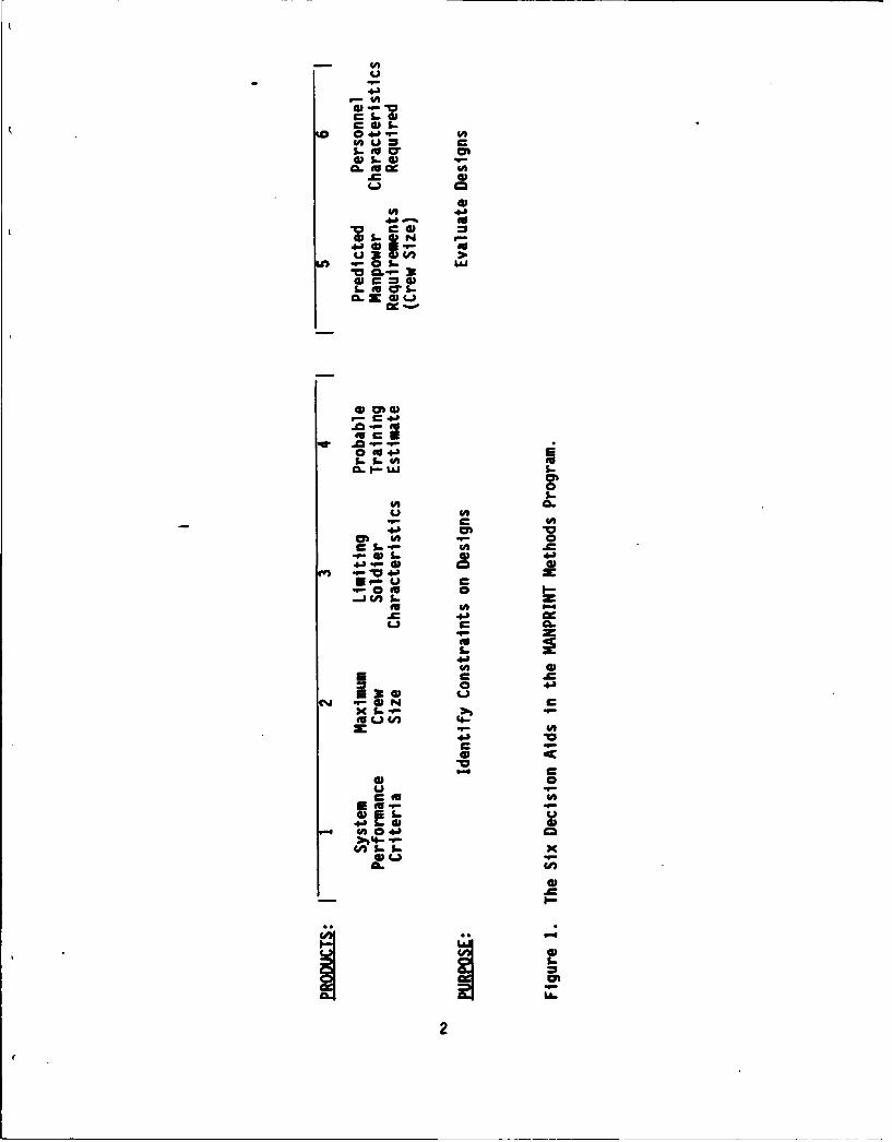
The 6 MANPRINT Products. The purpose of ARI's MANPRINT Methodsresearch program is to design and produce six automated MANPRINT decisionaids. Figure I illustrates the six decision aids.
Products 1 to 4 are concerned with the pre-design phase of systemdevelopment. These products are intended to influence system designs byidentifying constraints that will affect the new system's design. Product 1defines system requirements, including system performance criteria andreliability, availability, and maintainability requirements. Product 2estimates the maximum crew size that will be available to man the newsystem, Product 3 estimates the soldier characteristics of this crew, andProduct 4 focuses on likely available training for new system personnel.
Products 5 and 6 are to be used once the system design is available.These products are intended to evaluate system designs. Product 5 (thesubject of this paper) determines how many operators and maintainers will berequired to man the system. Product 6 will determine the characteristics ofthese operators and maintainers, and will identify any deficit betweenrequired and available personnel.
The logical relationship among the products is evident. Their useflows from aiding the design process to evaluating designs. Nevertheless,each product must be able to operate as independently as possible and beconvenient to use. These products will help the Army insure that itssoldiers will be able to operate and maintain system hardware and softwarein required numbers and at levels of performance that will ensure missionsuccess.
The Three-Phase Develooment Effort. This effort is being conducted inthree phases: concept development, detailed design specifications, andimplementation. (This document is the Phase 2 final report.) In responseto the request for proposals, many contractor teams developed approaches forall six products. Some teams were then selected to develop concepts forcertain products; three teams were selected for each product. Phase 1(October 1986 to June 1987) was concept development. Each team produced anarrative design document for evaluation.
The government then selected certain concepts to be further developedin Phase 2 (June 1987 to March 1988). One contractor team was selected forProducts 1, 2, and 4. Two teams were selected for Products 3 and 5. Allthree teams were selected for Product 6. The purpose of Phase 2 is toproduce a design specification document. (It is expected that down-selecting will occur at the end of Phase 2 for Products 3, 5, and 6). Given
1
u In
Lo r ImCL tI
.C a)
M c 0
M, 3
S- t S N
I-- EuaiS
CEC
0 '0t5-
.C-
CL' CL
Eu- C
04 0E F1 I-X Ln. % z
EuV U4mc 4.'
C aEu
0 .
I.-m4.'.
2

this document, a programmer could build the decision aid. Therefore, thePhase 2 document is unlike the usual Army Research Institute report; itcontains information geared toward computer programmers.
Phase 3 (April 1988 to September 1989) will be product development.Operational decision aids will be produced. In addition, steps will betaken during Phase 3 to ensure the acceptance of the product by Army users.(The acceptance plan for Product 5 is described in this report.)
The Product 5 Conceot
Product 5 is designed so that it will be accepted by Army users. Thisacceptance will depend on ease of use and accuracy of output. These twoaspects of the Product 5 concept are described below.
Ease of Use. The Product 5 interface emphasizes consistency and placesminimal memory demands on the user. Product 5 is menu driven; the menuformat is consistent. Submenu and data entry form layouts are alsoconsistent. In addition, Oroduct 5 will incorporate vocabulary common tothe other MANPRINT decision aids. Jargon will be avoided.
The Product 5 interface has been designed around a commercial off theshelf relational data base management package, R:BASE System V. Thispackage was selected by the contractor teams as the preferred data basemanagement package for the MANPRINT Methods decision aids. The interfaceand structure of Product 5 is compatiable with R:BASE System V.
Product 5 will place minimal memory demands on the user. The user willalways know where he is in the menu structure through use of a locationindicator on the screen. The extensive help facility will also lessenmemory demands. The help facility will provide a definition of all menuitems. The help facility will also provide a definition of each block on aform so that the user will know what type of entry is required. Suggestedsource documents advising the user where to find pertinent or better inputdata will be available through the help facility.
Product 5 makes the user's task easy by providing structured data entryforms and default values which need only to be modified. We plan toconstruct templates of performance objective conditions, functions, tasks,and times, for each system type. This will structure the useris task,provide the required information to the Product, and the user will only haveto modify the template as necessary. This templating avoids completely themyriad problems that would ensue if users were required to enter free textdata.
Accuracy of Output. Accuracy of output is affected by two factors:quality of input data and quality of the process by which the manpowerestimates are calculated.
Figure 2 presents the relation of input and output data quality. Inputdata quality improves over time as system designs become more refined.Users will be advised as to the level of confidence they can place in the
3

2 a
0 +J)
m
-)
C 0E1111 4.)
2 4c t
E Eu
Li4i41,
0.
0 t~0
< LL.
. 4.

accuracy of the output data, depending on the quality of their input data.Users will also be told which input data need improving.
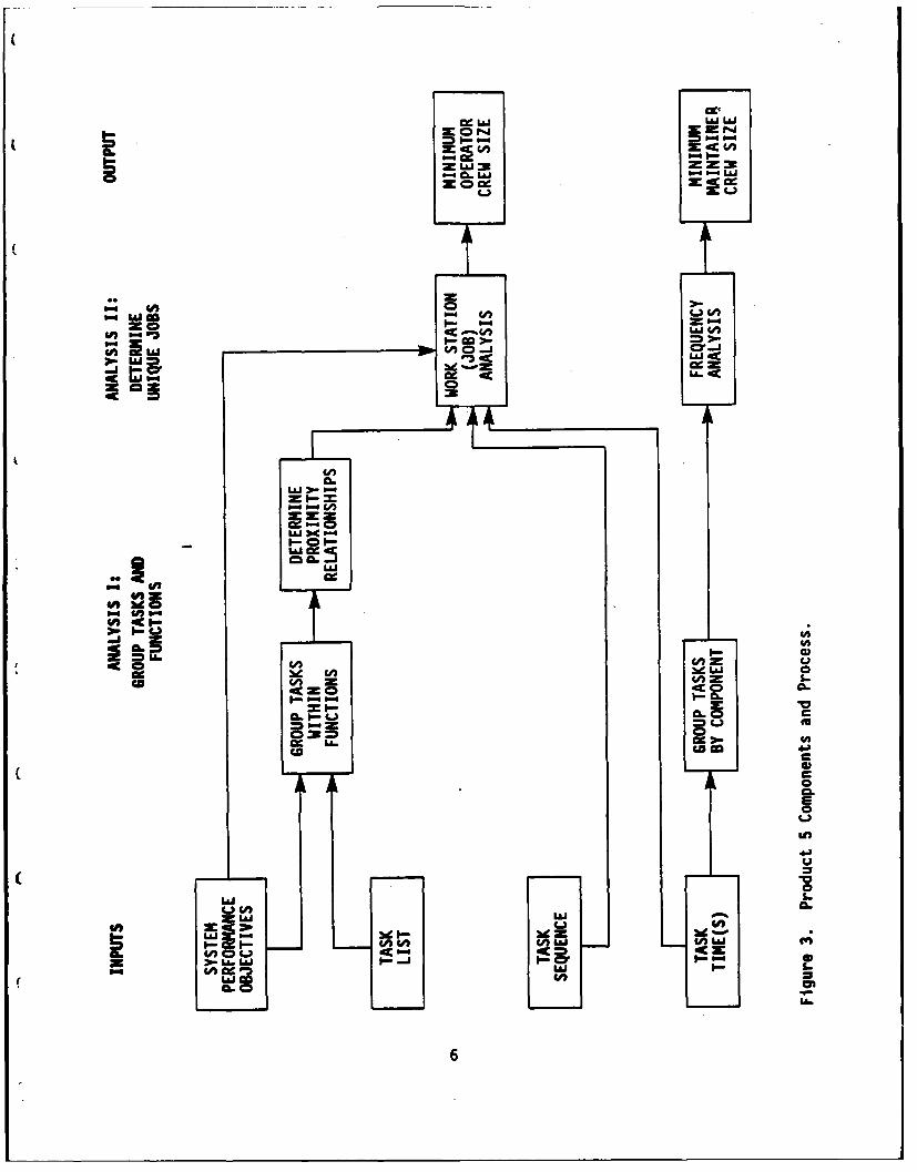
Figure 3 presents the process by which Product 5 will estimate manpowerrequirements. Operator and maintainer manpower estimates are madedifferently.
The operator crew size calculation is based on the assumption that ajob should be composed of tasks that are related to the same or similarfunctions, and that a person can only be one place at a time and can only doone thing at a time. Operator tasks are first grouped by function; a job isformed by using tasks within a function - this ensures that the job is builtfrom tasks that are related. Next, the proximity relationships betweenfunctions are determined. The idea is that if a job is formed using tasksfrom Function X, but there is still space left in the job for more tasks,those tasks will be drawn from the next closest function. This minimizesmovement for a soldier performing a job with tasks from more than onefunction. Product 5 assumes that a person can only be one place at a time,and that a job should contain tasks that are proximal. Next, unique jobsare formed using a standard network-precedence algorithm. This algorithmproduce$ unique jobs, their tasks and task times, as well as an assessmentof how well the job meets mission time criteria. If the design does notmeet mission criteria, the user can test alternate designs until one or moreis identified that appears feasible.
The maintainer crew size calculation is a straightforwardmultiplication of task times by yearly task frequencies divided by thenumber of work hours in a person year. The available data do not supportthe calculation of maintainer manpower using the network precedencealgorithm.
Product 5 Phase 2 Design Considerations
Interface with Products I and 6. Product 5 is designed to beindependent of the other MANPRINT products. This feature permits theProduct 5 user to generate an output without having to refer to otherproducts, which may or may not be located nearby. However, commonality invocabulary and an understanding of how the products fit together willimprove their functioning.
Product 1 generates system requirements. These requirements are statedin terms of mission, function, and task. The Kaplan and Crooks (1980)mission-function-task taxonomy was used as the basis for establishing asimilar taxonomy to be used by Product 1. This taxonomy was provided to theProduct 5 design team on August 3. The taxonomy is not ready for use, butan acceptable taxonomy will be developed during Phase 3. The use of sometaxonomy (whether it be Kaplan and Crooks or the Product 1 taxonomy) inProduct 5 Is described later.
Product 5 generates the number of operator and maintainer jobs requiredby a system design. It lists these jobs with their associated tasks, andthe criterion level at which the tasks must be performed.
5
czuj UJ LAJ
- % L&J P- P-4 LaJz 0
-)
=0A LAJ ccUcc
U)c I--
LLLi )oCP
(3 U) Z S.
wem
AL C
Nd w 0
Li CL.
ca co
L&J =A
z I L16P GDior1
U.
6
However, as mentioned above, the taxonomy to be used by the products isstill in development. Product 6 then describes the soldier characteristicsof these operators and maintainers. Product 6's analysis of Product 1requirements and Product 5 manpower requirements allows Product 6 to staterequired soldier characteristics.
It is hoped that automatic communication between Products 1, 5, and 6will save the time-consuming step of manually entering shared data. As afirst step in this direction, the products will share many records in therdata dictionary. Product I has provided its first-cut interfacespecification It is not compatible with R:BASE System V in its presentform, but it will be modified significantly early in the next phase so thatit can easily pass on data to the other decision aids using R:BASE.
Specifications for all MANPRINT Products. The contractor PrincipalInvestigators and our government manager, Dr. Kaplan of ARI, have agreed onhardware, software, and interface specifications for all the MANPRINTproducts. These are summarized below.
All products will run on an IBM AT type computer with hard disk with atleast 20 megabytes of storage. The products will be equipped with:enhanced graphics display, enhanced graphics board, 80286 processor,Bernoulli Box with two removable 20 megabyte disks, 80287 board forintensive floating point computations, 1200/2400 baud internal Hayes-compatible modem, 360 KB floppy drives, and dot matrix printer with 132characters per inch which can emulate IBM Graphics and Epson FX/LQ seriesprinters.
DOS 3.2 will be the operating system. Requirements for extended memorybeyond 640 KB up to four megabytes will be handled via the EMS standard.R:BASE System V will be the data base management package. Microsoft C willbe the programming language. Programs and data bases will be available onBernoulli disks.
Product operation will be simple and self-evident as possible. Theuser will not have to memorize command language. If hierarchically nestedmenus more than two levels deep are used, the user must know where in themenu structure he is; the menu locator must be common across all products(commonalities across products have not been agreed upon as of thiswriting). The present design for Product 5 calls for two levels of menu anda deeper level of template. If a complete product run takes more than threehours, the interface must be able to return the user to last point inprevious session, and inform the user which steps have been completed andwhich are remaining. Computer and psychology jargon should be avoided,unless the word is now in the common domain. Function key and color codesmust be standard across products (to be agreed upon later).
Housekeeping procedures (e.g., closing, saving, restoring) should becommon across products (to be agreed upon later). File names must bedisplayed so that users can select them. Select file procedures should becommon across products. Editing (entering, deleting, altering, moving, andcopying text) conventions should be common across products. These
7
conventions include keys for moving cursor, deleting, entering, and copying.These conventions should be simple and self-evident.
Users should be able to change the foreground and background colorsfrom light to dark. Each product must include an enhanced graphics driverand printer drivers that will operate IBM Graphics and Epson FX/LQ printers.
Training will be handled by a self-evident interface and/or built-inhelp facility; off-line training materials will be developed only if thetraining need can not be handled on-line. An on-line glossary will beprovided.
Approach to Product 5 Detailed Design Specification
The SAIC Product 5 team has conducted two important activities duringthis phase of design specification. These activities are analysis anddesign. The objective of analysis is to create a detailed specification ofsystem requirements, in other words to describe what Product 5 has toprovide. The object of design is to derive a solution to the problem, inother words to describe how Product 5 is to be implemented in order tosatisfy the requirements detailed during analysis.
The selection of techniques for analysis and design for implementationdepend upon the specific nature of the product. Traditional techniques areappropiiate for Product 5, which is an information-based application. Theformalization of the human interface, software, and data bases areconcurrent activities and serve to complement and feed one another. Theresultant specifications produced by these activities share information, butdepict it in different forms. Therefore, it is important that thespecifications be consistent with one another.
Consistent displays for analysis in this report have been developed forthe user interface, the software, and the data bases. The user interface isexpressed in menu map with data entry templates and a high level statetransition diagram. The software is expressed in leveled data flow diagramsand a structure chart (deMarco, 1978; Page-Jones, 1980). The data base isexpressed using entity relationship diagrams and entity definitions. Table1 presents the three Product 5 components (human interface, software, databases) and the techniques chosen to describe them, in both analysis anddesign. These displays are described below. The specifications for thedata base designs are directly implementable.
Menu Map and Data Entry Templates. The menu map presents thehierarchical menu structure. Two levels of menu are used, and a deeperlevel of data entry templates. The menu levels and data entry templateshave been developed in accordance with R:BASE System V and are presented inthis report.
State Transition Diagram. State transition diagrams are useful inmodeling user-product interactions. They show computer action (states),user action (operators) which enable states to change, and indicate temporal
8

Table 1. Product 5 Components and Analysis/Design Techniques.
TECHNIQUESProduct 5Components Analysis Deign
Human Interface Menu maps Report templatesData entry templatesHigh level state transition
diagram
Software Leveled data flow diagrams Structure chart
Data Bases Conceptual entity Implementation entityrelationship diagrams relationship diagrams
Conceptual entity definitions Implementation entity(data dictionary) definitions
9
sequence with arrows as in a flow chart. We developed a high level statetransition diagram for this document.
Data Flow Diagrams. Data flow diagrams are hierarchical graphicalexpressions of the exchange of information among logical data transformationobjects of Product 5. Data flow diagrams consist of three symbols:circles which represent processes, parallel lines which represent datastores, and vectors which represent data flow (in the manner of DeMarco,1978). Data flow diagrams are leveled. The highest level, Level 1,represents all of Product 5. The Level 2 and 3 diagrams expand on the mostimportant processes (circles) in the Level I and 2 diagrams, respectively.
Structure Chart. The structure chart depicts the data flows in Product5's primary algorithm. This is the network precedence algorithm used tocreate unique operator jobs.
Entity Relationship Diagrams and Data Dictionary. The entityrelationship diagram depicts system data entities and the relationshipsamong them. From this diagram, the entity definitions which depict entityattributes and their properties (e.g., type, precision) are developed.These are presented in tabular form in this report.
Relationship of Software and Data Base Design
The activities of software and data base analysis and design areconcurrent activities. These concurrent activities serve to complement oneanother, and as the specifications for the two activities share dataspecifications (for software data stores, for data base entities), thesespecifications provide a means by which their consistency may be checked.
Software Design Feeds Data Base Design. The ability of software designto feed data base design is best described by showing that the relationshipbetween (1) data flows and data stores of the data flow diagrams, (2) datastores and entity relationship models, and (3) data flows and entityrelationship models.
The relationship between data flows and stores in the data flow diagramis a natural one. Data stores represent a time repository of data thatprovide for the communication of data among processes. The conventions ofthe methodology constrain the data store to assume the name of respectiveincoming/outgoing data flows.
The relationship between data stores and the information represented inentity relationship models is less direct. Data stores may represent someparticular information about some data object entity, or they may representthe relationships between data object entities.
But data stores may also correspond to information that is not to bemaintained in the data bases (e.g., message queues). Deriving entity modelsfor the processes of the data flow diagram necessitates the need for amanual process during which the data stores that actually correspond toinformation to be maintained in the data base are identified. Further,
10
because data stores (individually) often represent only pieces ofinformation about some specific data object, and (together) often reflectredundant information, data stores must be logically combined to non-redundantly reflect that information to be maintained about a data object.
There is, then, a transitive relationship between data flows and entitymodels. The sum of the data flows acting upon the data stores logicallycombined to form data object entities depicts the required user/applicationprocess transactions against the data object. These data flows representtransactions that create, delete, or use instances of the respective dataobject (or some subset of it), or relationships between it and other dataobjects. It is important to logically group and document these transactionsaccording to data object and data object entity, because the globalconceptual and implementation schemas must be specifically designed tosupport these transactions.
Data Base Design Feeds Software Design. Just as the activities ofsoftware design function to provide input to the data base design effort, sodoes the data base design activity help to feed the software design effort.The major input from data base to software design is the detailing of thecomposition of data objects.
As the data flow diagram is detailed along successively lower levels,software designerslrequire more specific information about the detailedcomposition of data objects. In other words, at some time in the softwaredesign-effort, software designers will inevitably ask "Just what informationcomprises data object A?" For software designers, this information isnecessary to understand the processing required to manipulate the specificdata object in such a manner to support that functionality required bysoftware. Later in the design of software, data base design provides thedetails to perform data access functions and the interface with modulelogic.
11
ii
HUMAN INTERFACE ANALYSIS/DESIGN
Menu Map and Screen States
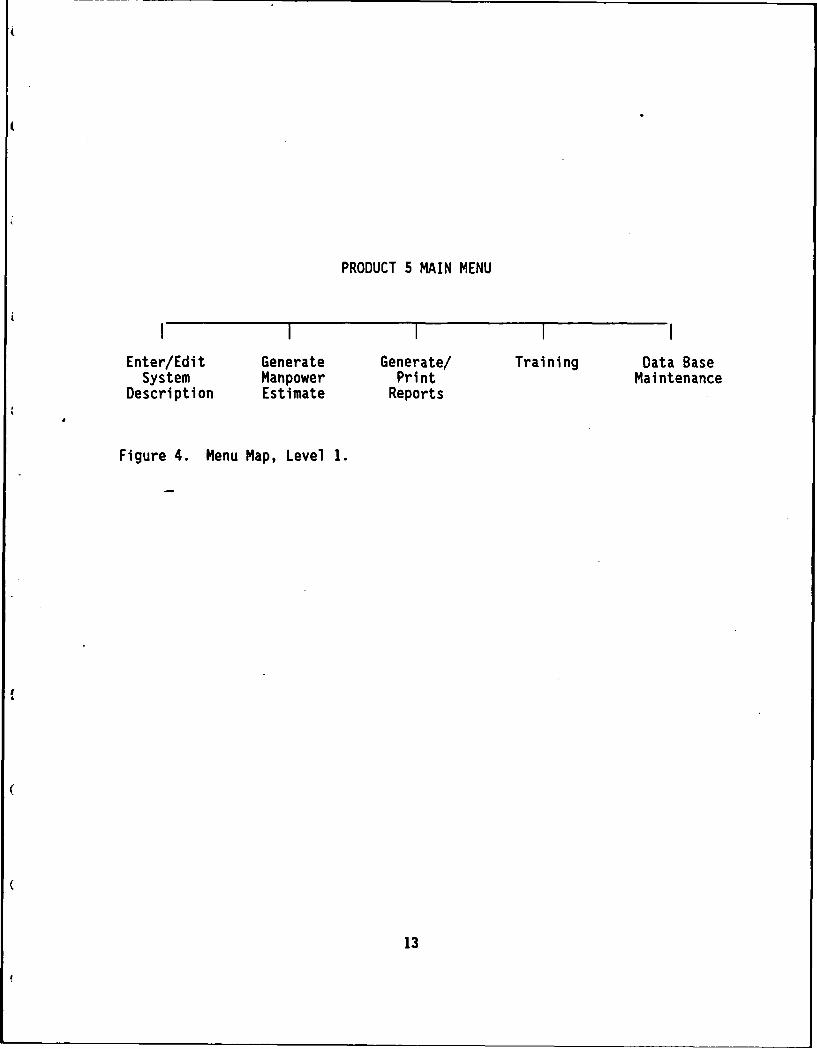
Levels of Menu. Product 5 uses a hierarchical menu structure. Figure4 presents the Level 1 menu map (main menu). Figure 5 presents the Level 2menu map.
Screen States/Data Entry Forms/Report Formats. Figures 6-12 presentthe data entry forms and screen states that correspond to each of the 5 MainMenu options used by Product 5. The screens meet R:BASE System Vspecifications. A summary of these specifications is presented in AppendixA, along with sample illustrations from the R:BASE System V manuals.Briefly, the screens support 1:1 and 1:Many relationships. The screens havetwo parts, the top part is the master (the 1 in the relationships), and thebottom part is the detail (the many in the relationships). The readershould note that the screens included in this report representstraightforward R:BASE designs. It is possible with R:BASE, however, toemploy other interfaces. These will be studied as necessary, during Phase3.
Figure 6 presents the main menu screen. Figures 7 and 8 corresponds toMain Menu 1: Enter/Edit System Description. Figures 7 and 8 present dataentry forms for operator and maintainer manpower calculations, respectively.
Figure 9 corresponds to Main Menu 2: Generate Manpower Estimates.Screen states are shown for generating operator and maintainer manpowerestimates.
Figure 10 corresponds to Main Menu 3: Generate/Print Reports. Reportsare first generated, then they may be saved to a file. Subsequently, thereport may be printed from the file and not generated again. A report isavailable for each data entry form and overall manpower estimate. There arealso convenience options to allow a user to request all forms available foroperators and maintainers for a given system.
Figure 11 presents the Training Menu which is Main Menu Option 4.Product 5 will include seven units of training, including four basic unitsand three advanced units. The lessons will be written during Phase 3, butwill follow the scheme described below.
For each unit, specific instructional objectives will be identified.The instructional strategy used in addressing these objectives assumes:students must have frequent practice in the objective under study; studentmastery progresses from knowledge about the concept, to a beginning-levelapplication, to advanced level application; student progress should bemeasured from before to after training; student progress should beacknowledged with a certificate. The following is the general progressionof each embedded training lesson.
1. Title screen
12
&
PRODUCT 5 MAIN MENU
I illI
Enter/Edit Generate Generate/ Training Data BaseSystem Manpower Print Maintenance
Description Estimate Reports
Figure 4. Menu Map, Level 1.
13

-C a
go - 4a
-. i a
:.sWO4.
La.
Cj2.06 C 6 1
x .- 80 C-4LC4Z~3
tit
54.6 a.
;~3 1-0uS *a4L
-40 .3
C a.
5-S 663-5 .
0 I- = a 1.
F 0 3c
00
-3-EQ. LILL. I0.-C1- 606 I&A ~ C4. 7
146

ANPRINT Manpower Estimation Aid Main Menu
(1) Enter/edit a system description(2) Generate a manpower estimate(3) Generate/print reports(4) Training(5) Database maintenance(6) Exit
Enter USER password: xxxxx
Type the number of your choice and press ENTER.Or use arrow keys, tab key or space bar to highlight number in the menu, andthen press ENTER.Press F1O for HELP.----------------------------------------------------------------------
Figure 6. Main Menu.
15

FbMENU 1 Form 1 Specify Source/Destination Data BaseEnter data base name: xxxxx
That data base does not exist. You will need to create one by modifying thedefault-system data base as necessary.
Specify read password: xxxxxSpecify write password: xxxxx
OR
The data base for your system exists.Date of last session with that data base was xxxxx.(ESC) Done (FX) Data base directory (F1O) Help (Shift F1O) More
Figure 7. Option 1: Operator Input Data.
16

[MENU I Form 2 Specify System Type and Taxonomy
Enter system type: xxxxx
Enter system name: xxxxx
(Only for new data bases) This decision aid is designed with a standardsystem-function-task taxonomy. We strongly advise you to use thetaxonomy, rather than delete the decision aid's taxonomy and type in yourown. (Of course, you may need to enter an occasional important functionor task name if you do not find it listed, or delete functions and tasksthat do not apply).
Do you wish to use the standard terms and taxonomy? xxxxx
(ESC) Return (FX) System type directory (FIO) Help
Figure 7 (Continued). Option 1: Operator Input Data.
17

Menu 1.1 Enter/Edit Operator or Maintainer Information
(1) Enter/edit operator information(2) Enter/edit maintainer information(3) Exit,
(FlO) Help
Figure 7 (Continued). Option 1: Operator Input Data.
18

t enu 1.1.1 Enter/Edit Operator Information
(1) Enter/edit operator performance conditions(2) Enter/edit operator functions, tasks, and times(3) Enter/edit operator task sequences(4) Enter/edit operator functions data(5) Exit
Enter user password: xxxxxEnter modify password: xxxxx
Maximum number of operators possible: xxxxx
(ESC) Done (F1O) Help
Figure 7 (Continued). Option 1: Operator Input Data.
19
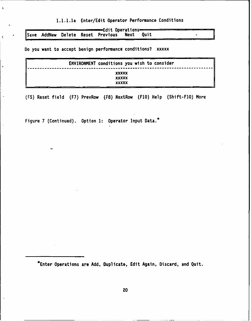
1.1.1.la Enter/Edit Operator Performance Conditions
Edit Operations
Ilsave AddNew Delete Reset Previous Next Quit
Do you want to accept benign performance conditions? xxxxx
ENVIRONMENT conditions you wish to consider-iii------------------------l------ml--------------l----i---------l----l----
xxxxxxxxxxxxxxx
(F5) Reset field (F7) PrevRow (F8) NextRow (F1O) Help (Shift-FlO) More
Figure 7 (Continued). Option 1: Operator Input Data. *
*Enter Operations are Add, Duplicate, Edit Again, Discard, and Quit.
20
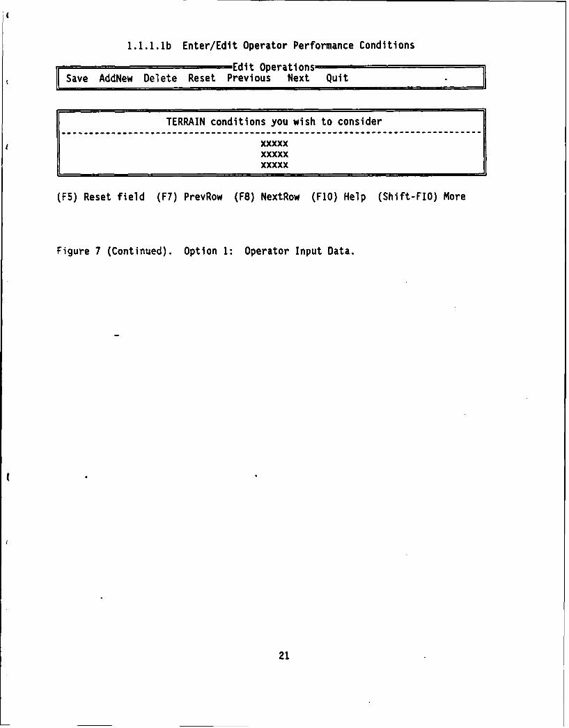
1.1.1.1b Enter/Edit Operator Performance Conditions
Save dEdit OperationsddNew Delete Reset Previous Next Quit
TERRAIN conditions you wish to consider
I xxxxxI xxxxx1. xxxxx
(F5) Reset field (F7) PrevRow (F8) NextRow (F1O) Help (Shift-FlO) More
Figure 7 (Continued). Option 1: Operator Input Data.
(
21
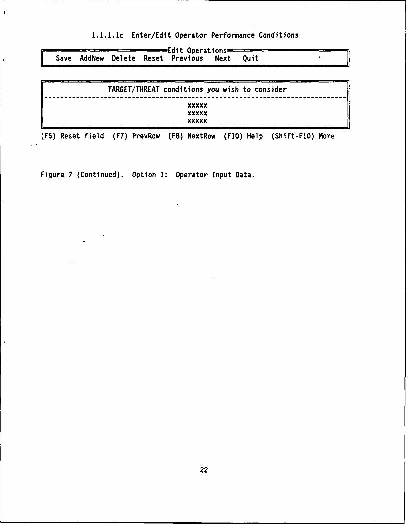
1.1.1.1c Enter/Edit Operator Performance Conditions
Edit OperationsSave AddNew Delete Reset Previous Next Quit
TARGET/THREAT conditions you wish to consider
xxxxxxxxxxxxxxx
(F5) Reset field (F7) PrevRow (F8) NextRow (F1O) Help (Shift-FlO) More
Figure 7 (Continued). Option 1: Operator Input Data.
22

1.1.1.1d Enter/Edit Operator Performance Conditions
Edit Operations
Save AddNew Delete Reset Previous Next Quit
FRIENDLY conditions you wish to consider------ l----ll---l-l-----llli----l---llli---lli----i----l-illil-----l-------l
xxxxxxxxxxxxxxx
(F5) Reset field (F7) PrevRow (F8) NextRow .(FIO) Help (Shift-FlO) More
Figure 7 (Continued). Option 1: Operator Input Data.
23

1.1.1.2 Enter/Edit Operator Functions, Tasks, and Times
SaeAd~w eet estEdit Operations iSave AddNew Delete Reset Previous Next Quit
Function: xxxxxFunction time requirement: xxxxx
Tasks Number of soldiers Task Time (Actual)required to do this task
----------i-----i------i------------i-i----i---i----i---ii-i-i---i----------
xxx xxxxx xxxxxxxxx xxxxx xxxxxxxxx xxxxx xxxxx
(F5) Reset field (F7) PrevRow (F8) NextRow (F1O) Help (Shift-FlO) More
Figure 7 (Continued). Option 1: Operator Input-Data.
24
XXXXXX XX
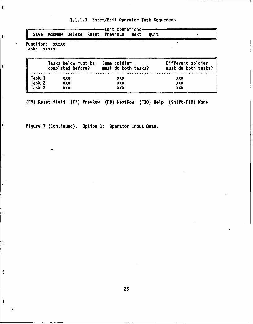
1.1.1.3 Enter/Edit Operator Task Sequences
Edit OperationsSave AddNew Delete Reset Previous Next Quit
Function: xxxxxTask: xxxxx
Tasks below must be Same soldier Different soldiercompleted before? must do both tasks? must do both tasks?
Task 1 xxx xxx xxxTask 2 xxx xxx xxxTask 3 xxx xxx xxx
(F5) Reset field (F7) PrevRow (F8) NextRow (FIO) Help (Shift-FlO) More
Figure 7 (Continued). Option 1: Operator Input Data.
25
(
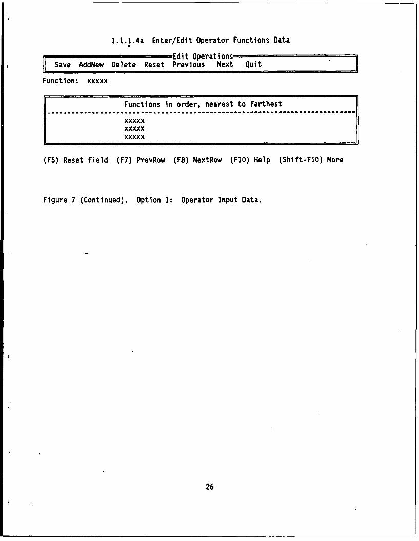
1.1.1.4a Enter/Edit Operator Functions Data
SaveAdd~w Deete esetEdit OperationsSav Ad~e Deet ReetPrevious Next Quit
Function: xxxxx
Functions in order, nearest to farthest
xxxxxF xxxxx11 xxxxx
F5) Reset field (F7) PrevRow (F8) NextRow (FIO) Help (Shift-FlO) More
Figure 7 (Continued). Option 1: Operator Input Data.
26
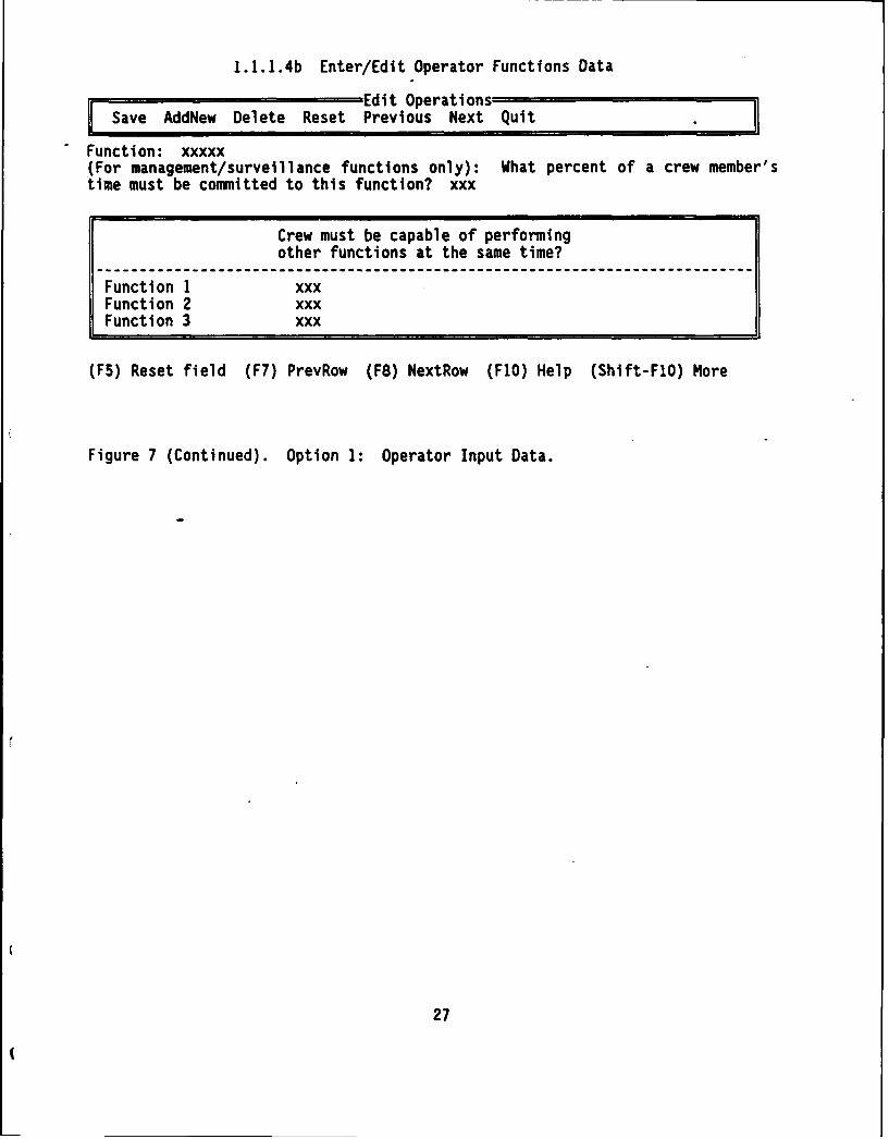
1.1.1.4b Enter/Edit Operator Functions Data
Save AdEdit OperationsSave AddNew Delete Reset Previous Next Quit
Function: xxxxx(For management/surveillance functions only): What percent of a crew member'stime must be committed to this function? xxx
Crew must be capable of performingother functions at the same time?
Function 1 xxxFunction 2 xxxFunction 3 xxx
(F5) Reset field (F7) PrevRow (F8) NextRow (F1O) Help (Shift-FlO) More
Figure 7 (Continued). Option 1: Operator Input Data.
27

IENU 1.1.2 Enter/Edit Maintainer Information
(1) Enter/edit maintenance criteria(2) Enter/edit maintainer subsystem/component data(3) Enter/edit maintainer component/task data(4) Exit
Enter user password: xxxxxEnter modify password: xxxxx
Enter maximum number of maintainers possible: xxxx
(ESC) Done (F1O) Help (Shift-FlO) More
Figure 8. Option 1: Maintainer Input Data.
28
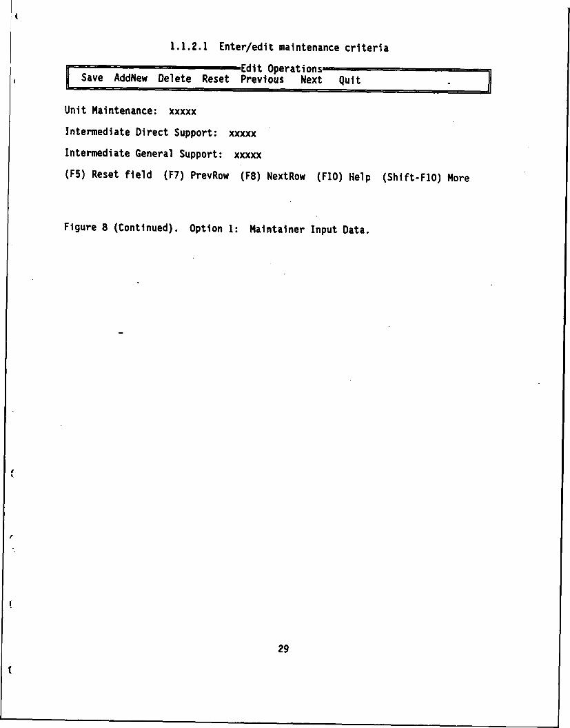
1.1.2.1 Enter/edit maintenance criteria
Se e DEdit OperationsSave AddNew Delete Reset Previous Next Quit
Unit Maintenance: xxxxx
Intermediate Direct Support: xxxxx
Intermediate General Support: xxxxx
(F5) Reset field (F7) PrevRow (F8) NextRow (F1O) Help (Shift-FlO) More
Figure 8 (Continued). Option 1: Maintainer Input Data.
29

1.1.2.2 Enter/Edit Maintainer Subsystem/Component Data
Sde D t e Edit OperationsSave AddNew Delete Reset Previous Next Quit
Subsystem: xxxxx
System components Quantity per application-llliliil-----i-il--ii-------------illi------iii------ii-ilil-lli----ill-----
xxxxx xxxxxxxxxx xxxxxxxxxx xxxxx
(F5) Reset field (F7) PrevRow (F8) NextRow (F1O) Help (Shift-FlO) More
Figure 8 (Continued). Option 1: Maintainer Input Data.
30
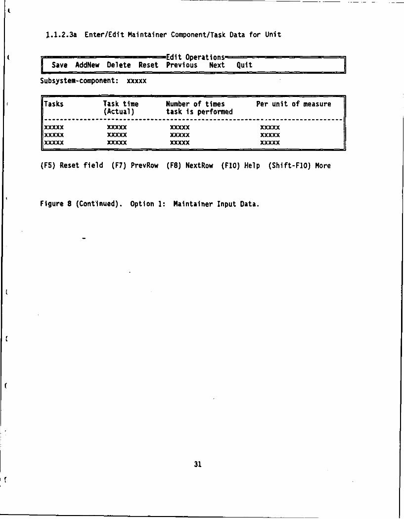
1.1.2.3a Enter/Edit Maintainer Component/Task Data for Unit
SaveAdd~w Deete eset Edit OperationsSaveAddew elee RsetPrevious Next Quit
Subsystem-component: xxxxx
Tasks Task time Number of times Per unit of measure(Actual) task is performed
xxxxx xxxxx xxxxx xxxxx---------------------------xxxxx xxxxx xxxxx xxxxxxxxxxxxx xxxxx xxxxx
(F5) Reset field (F7) PrevRow (F8) NextRow (FlO) Help (Shift-F1O) More
Figure 8 (Continued). Option 1: MaIntainer Input Data.
31

1.1.2.3b Enter/Edit Maintainer Component/Task Data for Direct Support
Save~~~~~ ;d~ Dlee Rst Edit Operations-=Sae Ad~e Dlet ReetPrevious Next Quit 7
Subsystem-component: xxxxx
Tasks Task time Number of times Per unit of measure(Actual) task is perfc-mied
----------------------------------------------------------------xxxxx xxxxx xxxxx xxxxxxxxxx xxxxx xxxxx xxxxxxxxxx xxxxx xxxxx xxxxx
(F5) Reset field (F7) PrevRow (F8) NextRow (F1O) Help (Shift-FlO) More
Figure 8 (Continued). Option 1: Nalntainer Input Data.
32

1.1.2.3c Enter/Edit Maintainer Component/Task Data for General Support
SaveAddew elee RsetEdit OperationsSave AddNew Delete Reset Previous Next Quit
Subsystem-component: xxxxx
Tasks Task time Number of times Per unit of measure(Actual) task is performed
xxxxx xxxxx xxxxx xxxxxxxxxx xxxxx xxxxx xxxxxxxxxx xxxxx xxxxx xxxxx
(F5) Reset field (F7) PrevRow (F8) NextRow (FlO) Help (Shift-FlO) More
Figure 8 (Continued). Option 1: Maintainer Input Data.
33
XXX XX XX XX

IENU 2 Generate a Manpower Estimate
(1) Generate operator manpower estimate(2) Generate maintainer manpower estimate(3) Generate operator and maintainer manpower estimates(4) Exit to Main Menu
(ENT) Select (F1O) Help
Figure g. Option 2: Generate Manpower Estimate.
34
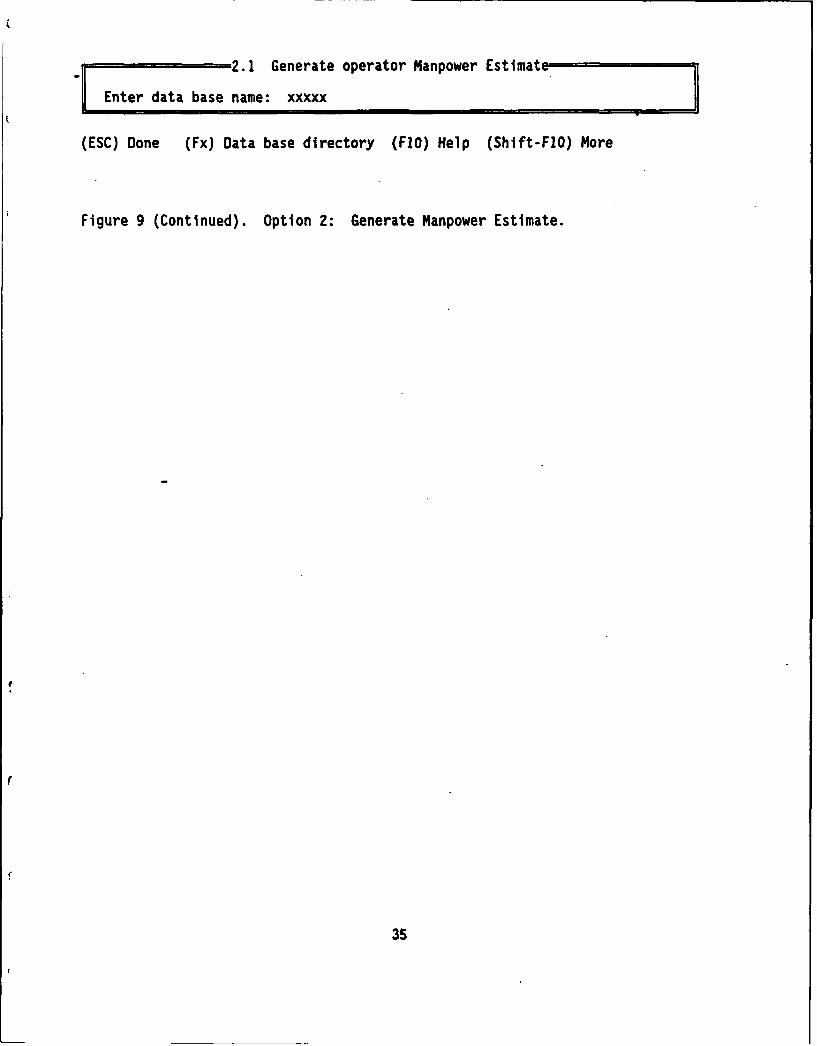
2.1 Generate operator Manpower Estimate.
FEnter data base name: xxxxx
(ESC) Done (Fx) Data base directory (FIO) Help (Shift-FIO) More
Figure 9 (Continued). Option 2: Generate Manpower Estimate.
35
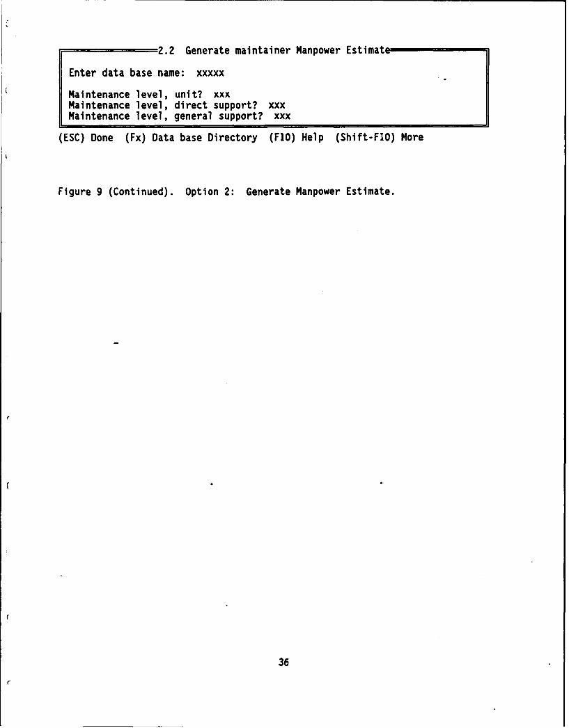
2.2 Generate maintainer Manpower Estimate
Enter data base name: xxxxx
Maintenance level, unit? xxxMaintenance level, direct support? xxxMaintenance level, general support? xxx
(ESC) Done (Fx) Data base Directory (FIO) Help (Shift-FlO) More
Figure 9 (Continued). Option 2: Generate Manpower Estimate.
36

2.3 Generate Operator and Maintainer Manpower Estimates
Enter data base name: xxxxx
All maintenance levels? xxxMaintenance level, unit? xxxMaintenance level, direct support? xxxMaintenance level, general support? xxx
(ESC) Done (Fx) Data base directory (FlO) Help (Shift-FlO) More
Figure 9 (Continued). Option 2: Generate Manpower Estimate.
37

MENU 3. Generate/Print Reports(1) Operator functions, tasks, and times(2) Operator task sequences
(3) Operator functions data(4) Operator Jobs and tasks(5) Print all operator reports
(6) Maintenance criteria(7) Maintainer subsystem/component data(8) Maintainer component/task data(9) Maintainer jobs and tasks(10) Print all maintainer reports
(11) Print an existing report file(12) Exit to Main Menu
User password: xxxxxRead password: xxxxx
(ENTER) Select (F1O) Help
Figure 10. Option 3: Generate/Print Reports.
( -
38
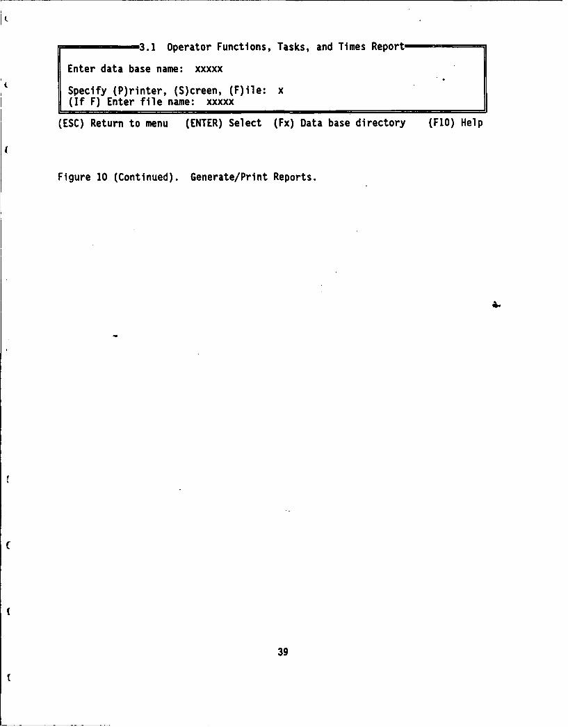
3.1 Operator Functions, Tasks, and Times Report
Enter data base name: xxxxx
Specify (P)rinter, (S)creen, (F)ile: x(If F) Enter file name: xxxxx
(ESC) Return to menu (ENTER) Select (Fx) Data base directory (F1O) Help
Figure 10 (Continued). Generate/Print Reports.
39
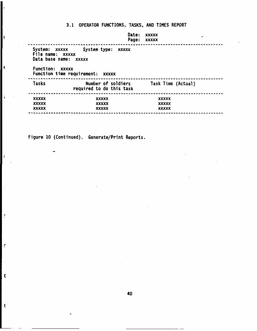
3.1 OPERATOR FUNCTIONS, TASKS, AND TIMES REPORT
Date: xxxxxPage: xxxxx
System: xxxxx System type: xxxxxFile name: xxxxxData base name: xxxxx
Function: xxxxxFunction time requirement: xxxxx
I--li-ll-----l-----------li--ii-------------------l------i--------l--l---lll--
Tasks Number of soldiers Task Time (Actual)required to do this task
xxxxx xxxxx xxxxxxxxxx xxxxx xxxxxxxxxx xxxxx xxxxx
Figure 10 (Continued). Generate/Print Reports.
40
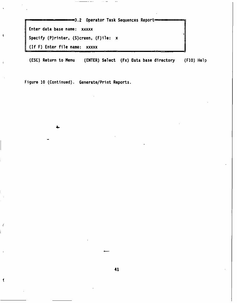
3.2 Operator Task Sequences Report
Enter-data base name: xxxxx
Specify (P)rinter, (S)creen, (F)lle: x
(If F) Enter file name: xxxxx
(ESC) Return to Menu (ENTER) Select (Fx) Data base directory (FIO) Help
Figure 10 (Continued). Generate/Print Reports.
44
41
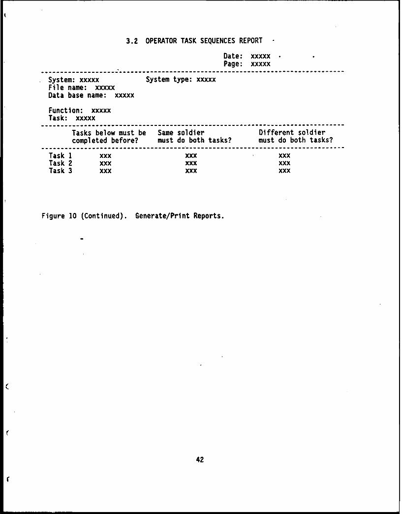
3.2 OPERATOR TASK SEQUENCES REPORT -
Date: xxxxxPage: xxxxx
-------------------------------------------------------------------------System: xxxxx System type: xxxxxFile name: xxxxxData base name: xxxxx
Function: xxxxxTask: xxxxx
Tasks below must be Same soldier Different soldiercompleted before? must do both tasks? must do both tasks?
Task 1 xxx xxx xxxTask 2 xxx xxx xxxTask 3 xxx xxx xxx
Figure 10 (Continued). Generate/Print Reports.
42
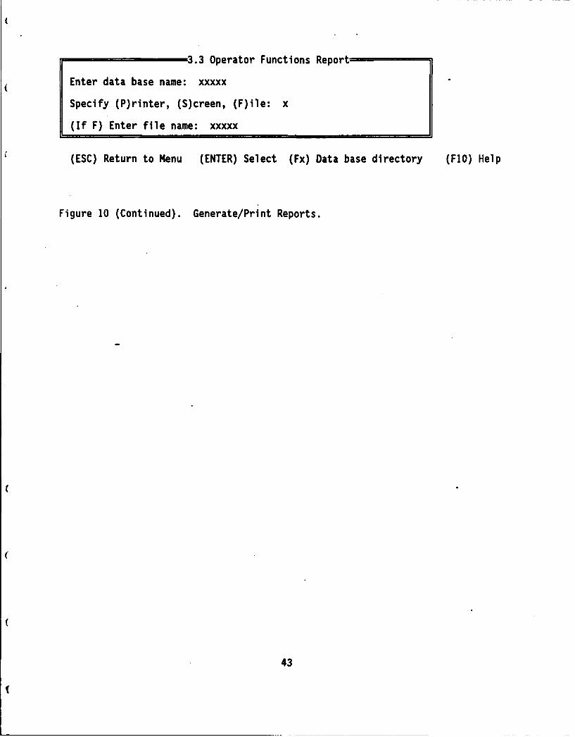
3.3 Operator Functions Report
Enter data base name: xxxxx
Specify (P)rinter, (S)creen, (F)ile: x
(If F) Enter file name: xxxxx
(ESC) Return to Menu (ENTER) Select (Fx) Data base directory (F1O) Help
Figure 10 (Continued). Generate/Print Reports.
43

3.3 OPERATOR FUNCTIONS REPORT
Date: xxxxxPage: xxxxx
System: xxxxx System type: xxxxxFile name: xxxxxData base name: xxxxx
Function: xxxxx
Functions in order, nearest to farthest
xxxxxxxxxxxxxxx
What percent of a crew member's time must be committedto this function? xxxxx
Crew must be capable of performingother functions at the same time?
-iiiiiii-------------------------------------------------------------------Function 1 xxxFunction 2 xxxFunction S xxx----------------------------------------------------------------------------
Figure 10 (Continued). Generate/Print Reports.
44
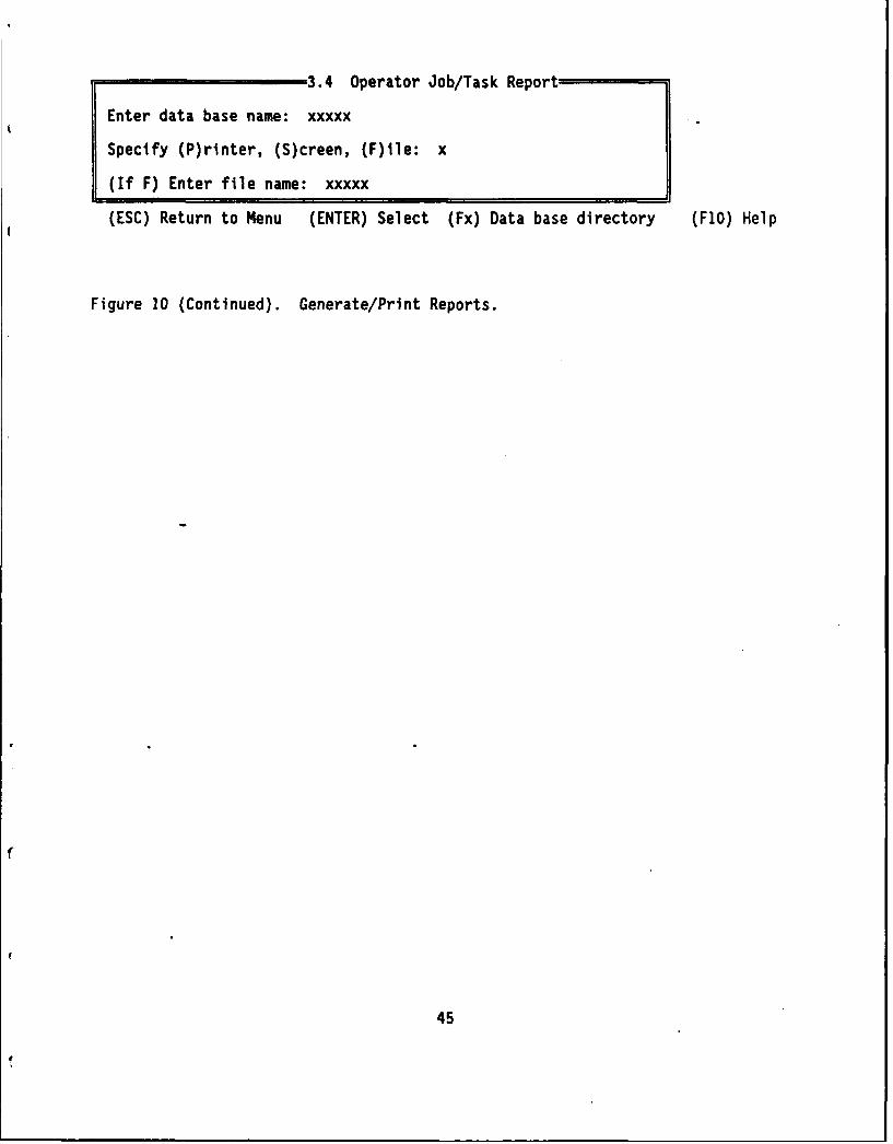
3.4 Operator Job/Task Report
Enter data base name: xxxxx
Specify (P)rinter, (S)creen, (F)ile: x
(If F) Enter file name: xxxxx
(ESC) Return to Menu (ENTER) Select (Fx) Data base directory (F1O) Help
Figure 10 (Continued). Generate/Print Reports.
45

3.4 OPERATOR JOB/TASK REPORT
Date: xxxxxPage: xxxxx
System: xxxxx System type: xxxxxFile name: xxxxxData base name: xxxxx
Environment: Terra-i: Target/Threat: Friendly:xxxxx xxxxx xxxxx xxxxxxxxxx xxxxx xxxxx xxxxx
Function: xxxxx Minimum number of Jobs estimated: xxxxxMaximum manpower constraint: xxxxxCriterion time to complete function: xxxxxActual time to complete function: xxxxx
Task Time Job xxxxxx Job xxxxx Job xxxxx Job xxxxxnnnnn xxxxx xxxxx xxxxx xxxxxnnnnn xxxxx xxxxx xxxxx xxxxxnnnnn xxxxx xxxxx xxxxx xxxxx
-----------------------------------------------------------------------System: Minimum number of jobs estimated: xxxxx
Maximum manpower constraint: xxxxxCriterion time to complete all functions: xxxxxActual time to complete all functions: xxxxxList of functions where criterion not met: xxxxxPercent default values used: xx
Task Time Job xxxxxx Job xxxxx Job xxxxx Job xxxxx--------------------------------------------------------------------nnnnn xxxxx xxxxx xxxxx xxxxxnnnnn xxxxx xxxxx xxxxx xxxxxnnnnn xxxxx xxxxx xxxxx xxxxx-----------------------------------------------------------------------
Figure 10 (Continued). Generate/Print Reports.
46
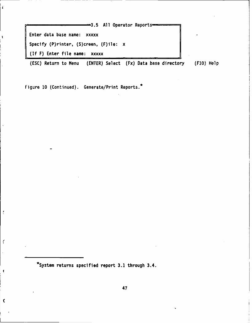
3.5 All Operator Reports
Enter data base name: xxxxx
Specify (P)rinter, (S)creen, (F)ile: x
(If F) Enter file name: xxxxx
(ESC) Return to Menu (ENTER) Select (Fx) Data base directory (F1O) Help
Figure 10 (Continued). Generate/Print Reports.*
*System returns specified report 3.1 through 3.4.
47
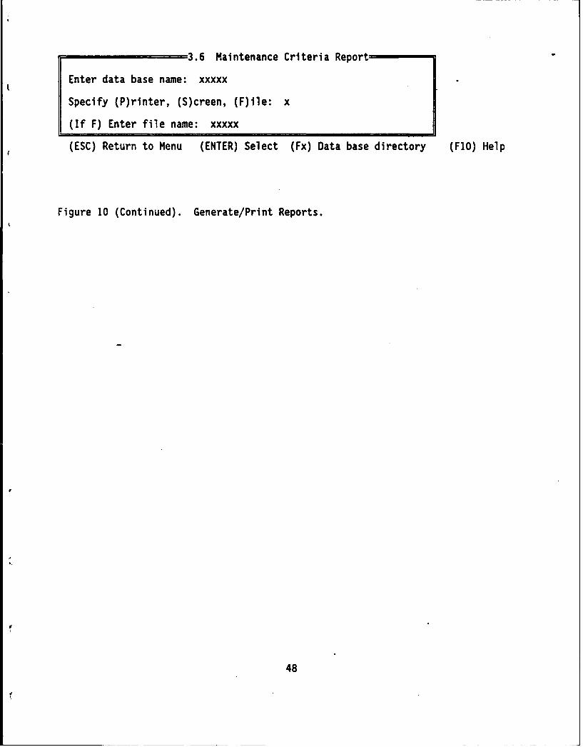
3.6 Maintenance Criteria Report
Enter data base name: xxxxx
Specify (P)rinter, (S)creen, (F)ile: x
(If F) Enter file name: xxxxx
(ESC) Return to Menu (ENTER) Select (Fx) Data base directory (FIO) Help
Figure 10 (Continued). Generate/Print Reports.
48

3.6 MAINTENANCE CRITERIA REPORT
Date: xxxxxPage: xxxxx
System: xxxxx System type: xxxxxFile name: xxxxxData base name: xxxxx
Unit: xxxxx
Direct support: xxxxx
General support: xxxxx
Figure 10 (Continued). Generate/Print Reports.
49

3.7 -Maintenance Subsystem/Component Report
Enter data base name: xxxxx
Specify (P)rinter, (S)creen, (F)ile: x
(If F) Enter file name: xxxxx
(ESC) Return to Menu (ENTER) Select (Fx) Data base directory (F1O) Help
Figure 10 (Continued). Generate/Print Reports.
50

3.7 MAINTENANCE SUBSYSTEM-COMPONENT REPORT
. Date: xxxxxPage: xxxxx
System: xxxxx System type: xxxxxFile name: xxxxxData base name: xxxxx
Subsystem: xxxxx
System components Ouantltv per application
xxxxx xxxxxxxxxx xxxxxxxxxx xxxxx
Figure 10 (Continued). Generate/Print Reports.
51
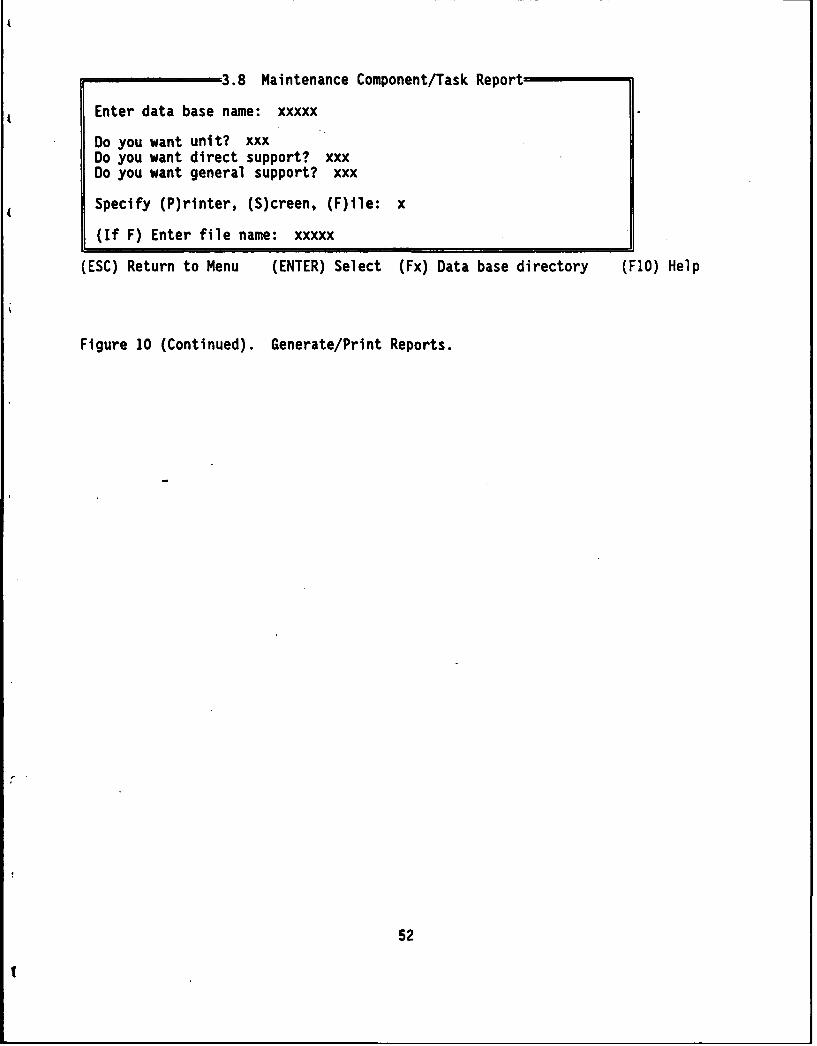
3.8 Maintenance Component/Task Report
Enter data base name: xxxxx
Do you want unit? xxxDo you want direct support? xxxDo you want general support? xxx
Specify (P)rinter, (S)creen, (F)ile: x
(If F) Enter file name: xxxxx
(ESC) Return to Menu (ENTER) Select (Fx) Data base directory (FIO) Help
Figure 10 (Continued). Generate/Print Reports.
52
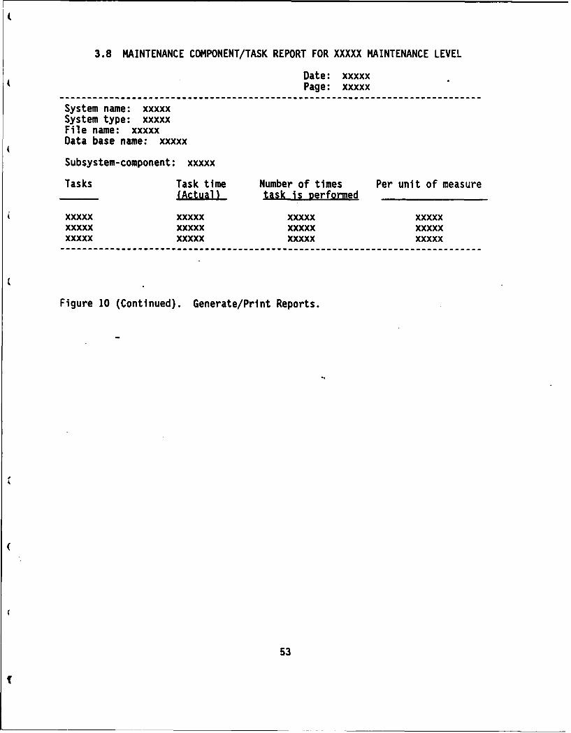
3.8 MAINTENANCE COMPONENT/TASK REPORT FOR XXXXX MAINTENANCE LEVEL
Date: xxxxxPage: xxxxx
System name: xxxxxSystem type: xxxxxFile name: xxxxxData base name: xxxxx
Subsystem-component: xxxxx
Tasks Task time Number of times Per unit of measure(Actual) task is performed
xxxxx xxxxx xxxxx xxxxxxxxxx xxxxx xxxxx xxxxxxxxxx xxxxx xxxxx xxxxx
Figure 10 (Continued). Generate/Print Reports.
53
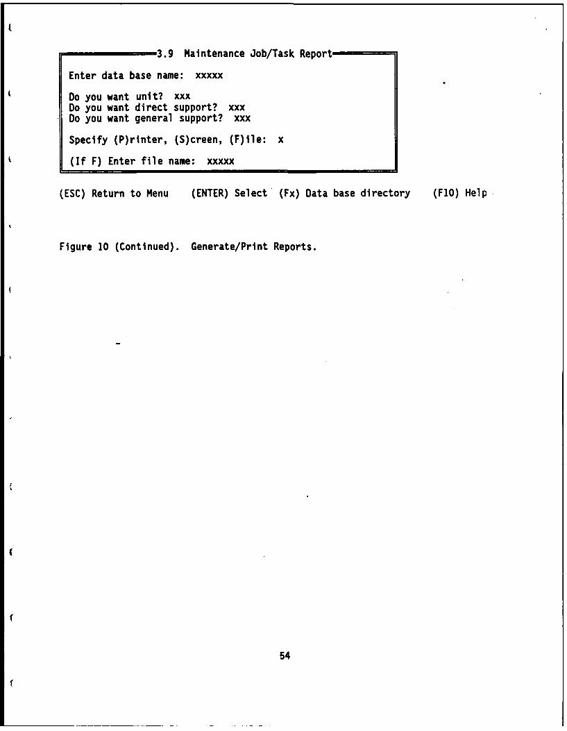
3.9 Maintenance Job/Task Report
Enter data base name: xxxxx
Do you want unit? xxxDo you want direct support? xxxDo you want general support? xxx
Specify (P)rinter, (S)creen, (F)ile: x
(If F) Enter file name: xxxxx
(ESC) Return to Menu (ENTER) Select (Fx) Data base directory (F1O) Help
Figure 10 (Continued). Generate/Print Reports.
54
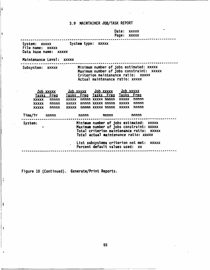
3.9 MAINTAINER JOB/TASK REPORTDate: xxxxxPage: xxxxx
i iili-------------------------------------------------------------------System: xxxxx System type: xxxxxFile name: xxxxxData base name: xxxxx
Maintenance Level: xxxxx------------------------------------------------------------------------Subsystem: xxxxx Minimum number of jobs estimated: xxxxx
Maximum number of jobs constraint: xxxxxCriterion maintenance ratio: xxxxxActual maintenance ratio: xxxxx
Job xxxxx Job xxxxx Job xxx ' Jb xxxxxTak ra Tasks Freo Tasks- Frea Tasks Fme
xxxxx nnnnn xxxxx nnnnn xxxxx nnnnn xxxxx nnnnnxxxxx nnnnn xxxxx nnnnn xxxxx nnnnn xxxxx nnnnnxxxxx nnnnn xxxxx nnnnn xxxxx nnnnn xxxxx nnnnn
Time/Yr nnnnn nnnnn nnnnn nnnnn
System: Minimum number of jobs estimated: xxxxxMaximum number of jobs constraint: xxxxxTotal criterion maintenance ratio: xxxxxTotal actual maintenance ratio: xxxxx
List subsystems criterion not met: xxxxxPercent default values used: xx
Figure 10 (Continued). Generate/Print Reports.
Ir
55

3.10 All Maintenance Reports
Enter data base name: xxxxx
Do you want unit? xxxDo you want direct support? xxxDo you want general support? xxx
Specify (P)rinter, (S)creen, (F)ile: x
(If F) Enter file name: xxxxx
(ESC) Return to Menu (ENTER) Select (Fx) Data base directory (FIO) Help
Figure 10 (Continued). Generate/Print Reports.*
*System returns specified report 3.6 to 3.9.
56
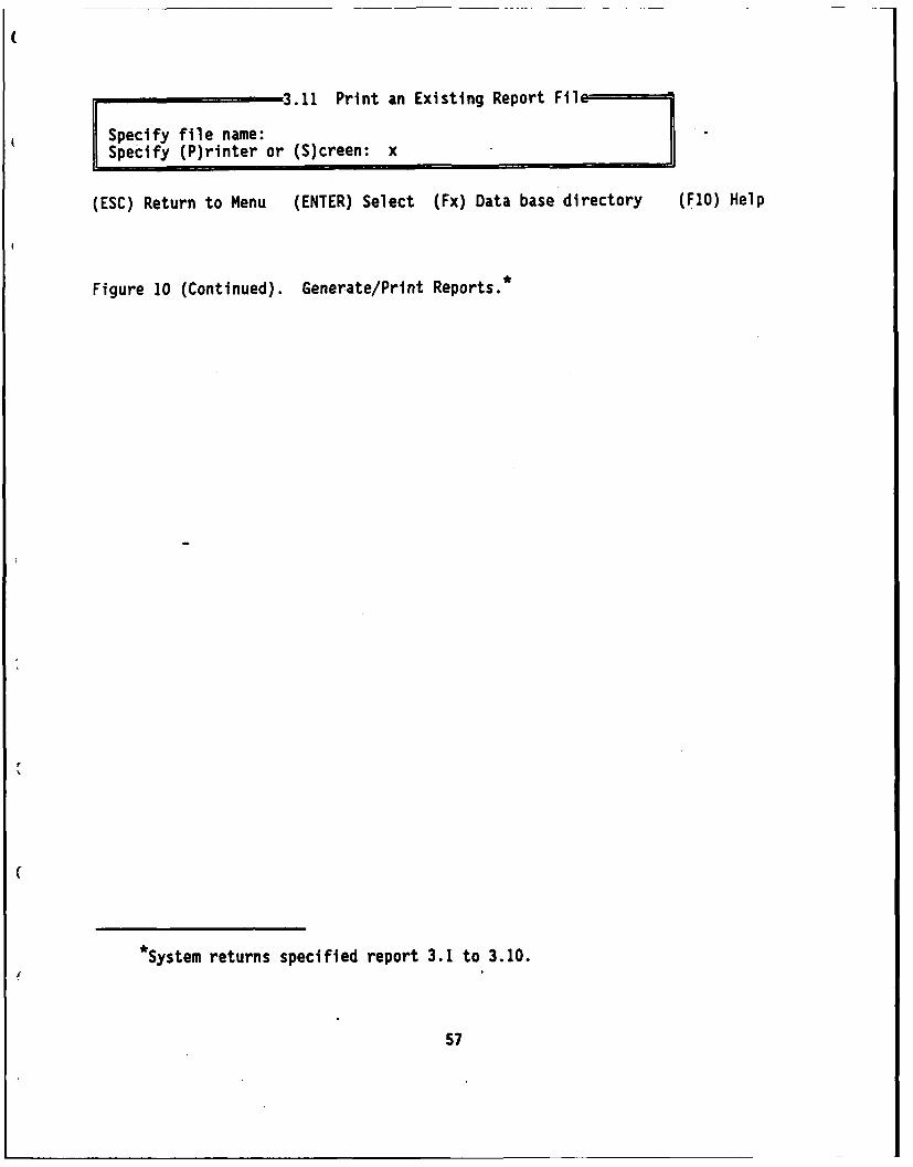
3.11 Print an Existing Report Filce=
Specify file name:Specify (P)rinter or (S)creen: x
(ESC) Return to Menu (ENTER) Select (Fx) Data base directory (FlO) Help
Figure 10 (Continued). Generate/Print Reports.*
System returns specified report 3.1 to 3.10.
57

MENU 4. Training
Select the lesson you want to use:
(1) How to use the on-line HELP!(2) Introduction to MANPRINT Manpower Estimation Aid, with sample(3) Input data requirements and practice(4) Understanding and interpreting manpower estimates(5) Advanced: How operator manpower estimates are generated(6) Advanced: How maintainer manpower estimates are generated(7) Advanced: How system design changes affect manpower(8) Exit to Main Menu
(ENT) Select (F1O) Help
Figure 11. Option 4: Training.
58
2. Statement of instructional objectives
3. Pretest (may be automatically scored or self-assessment type)
4. General sequence for each instructional objective:
a. Present concept
b. Require a student interaction
c. Automatic evaluation of student response; branch as required
d. Present concept/interaction/evaluation/branch sequence again asneeded
e. Require an acquisition-level application interaction, withevaluation and branching
f. Require a generalization-level application interaction, withevaluation and branching
5. After Step 4 has been accomplished for all instructionalobjectives, provide mixed (e.g., concept, acquisition application,generalization application) practice with feedback over all theobjectives. Three practice items are available for each objective.
- Evaluate and branch as required.
6. Unit posttest (automatically scored; includes two or three itemsper objective)
7. Print certificate of completion
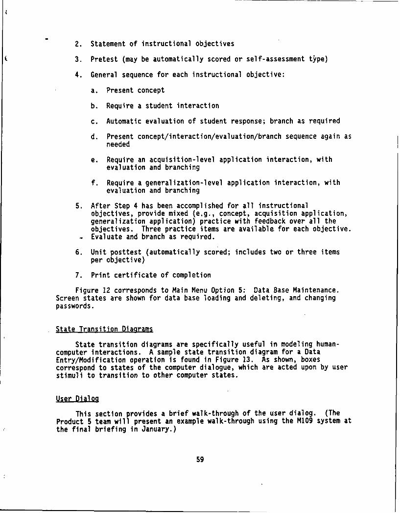
Figure 12 corresponds to Main Menu Option 5: Data Base Maintenance.Screen states are shown for data base loading and deleting, and changingpasswords.
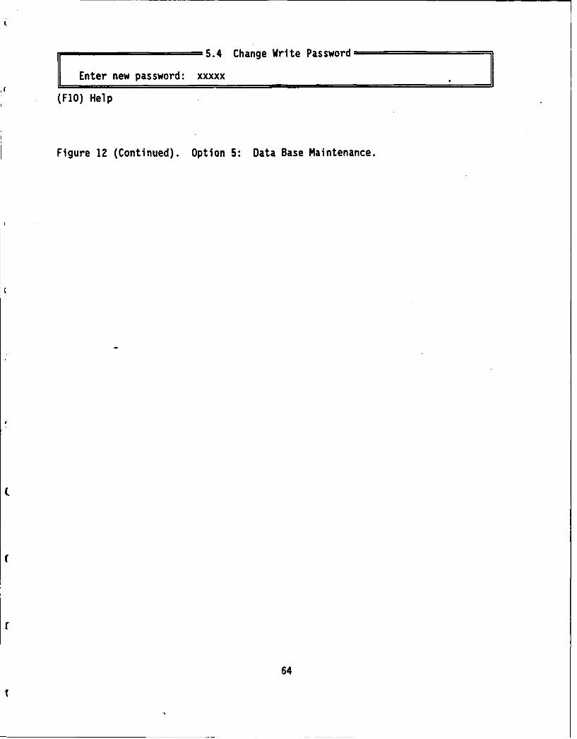
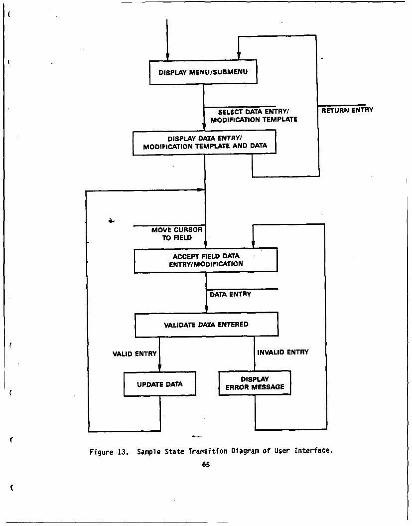
State Transition Diagrams
State transition diagrams are specifically useful in modeling human-computer interactions. A sample state transition diagram for a DataEntry/Modification operation is found in Figure 13. As shown, boxescorrespond to states of the computer dialogue, which are acted upon by userstimuli to transition to other computer states.
User Dialog
This section provides a brief walk-through of the user dialog. (TheProduct 5 team will present an example walk-through using the M109 system atthe final briefing in January.)
59

MENU 5. Data Base Maintenance
(1) Load new taxonomy(2) Delete data base(3) Change read password(4) Change write password(5) Exit to Main Menu
User password: xxxxx
(ENT) Select (Fx) Data base directory (Fl0) Help
Figure 12. Option 5: Data Base Maintenance.
60

5.1 Load New Taxonomy--=' 1
Specify directory location of files: xxxxx
(FlO) Help
Figure 12 (Continued). Option 5: Data Base Maintenance.
61

5.2 Delete Data Base I
Specify data base name: XXXXX
(FlO) Help
Figure 12 (Continued). Option 5: Data Base Maintenance.
62

5.3 Change Read Password
Enter new password: xxxxx
(F1O) Help
Figure 12 (Continued). Option 5: Data Base Maintenance.
63
5.4 Change Write Password
Enter new password: xxxxx
(FlO) Help
Figure 12 (Continued). Option 5: Data Base Maintenance.
64
DSPLY MENU/SUBMENU
SELECT DATA ENTRY/ RETURN ENTRY
MODIFICATION TEMPLATE
DISPLAY DATA ENTRY/MODIFICATION TEMPLATE AND DATA
(MO VE CURSOR'
TO FIELD
I ACCEPT FIELD DATA
ENTRY/MOOIFICATIONS
iDATA ENTRY
S VALIDATE DATA ENTERED
VALID ENTRY INVAUD ENTRY
UPDATE AT DISPLAERROR MESSAGE
Figure 13. Sample State Transition Diagram of User Interface.
65
Main Menu. Upon selecting options 1, 2, or 3 (see Figure 6), butbefore the requested submenu is displayed, the screen is cleared, and thefollowing prompt is given: "Enter User Password:" to which the usersupplies an R:BASE USER Password.
Menu 1: Enter/Edit a System Description (refer to Figure 7). Uponselecting this option, 2 forms are displayed in sequence, after which Menu1.1 is displayed. On Form 1, the user identifies the data base name. Ifdata base name exists, then intent to edit existing system description isrecognized, or else intent to enter a new system description is inferred.Forms are driven with R:BASE "EDIT" or "ENTER" accordingly.
On Form 2, the user identifies system type and name. The itemconcerning user acceptance of the standard taxonomy is displayed if "database name" for this USER password is not found, indicating the intent is toenter rather than edit.
Form 2 includes a function key (noted on the status line) associatedwith a query to display list of all system types. A user is not permittedto modify the system type of a system description data base which hasalready been populated based on the standard taxonomy.
Menu 1.1.1: Enter/Edit Operator Manpower Calculation (refer to Figure7). If user has accepted the standard taxonomy, then a copy of the portionof the taxonomy pertaining to the system type is made to "data base name"with OWNER password set to USER password. There is no problem if the userat a later time wishes to add maintainer information to operatorinformation, or vice versa.
If USER password does not equal OWNER password, after the user selectsan option from Menu 1.1.1 or Menu 1.1.2, but before the respective form isdisplayed, the user is prompted for a modify password. If the USER passworddoes not equal modify password, then a message is displayed and the usernever sees the requested form.
There are four data entry forms for operator manpower calculations:designating performance conditions; editing functions, tasks and times;determining task sequences; and, determining distance between functions.
Product 5 uses as a default benign performance conditions (Menu1.1.1.1). The user may accept these, or select conditions he or she wishesto consider. The four categories of performance conditions shown in thescreens come from the draft Product 1 conditions taxonomy. Product 5 willcategorize performace conditions and combinations into three categories:low, medium, and high. Low means that the environment is not severe andperformance times are shortest. Medium is a medium severe environment, andthere will be some degradation, i.e., increase in task time. High is asevere environment, and task times will be even longer. We will usedegradation factors developed from Siegel, Pfeiffer, Kopstein, Wilson, andOzkaptan (1979). In addition, we will degrade task times for tasks that aresusceptible to degradation, to be developed from Siegel et al. (1979).
66
Next the user enters/edits operator functions, tasks, and times (Menu1.1.1.2). One function is presented per screen. The function timerequirement comes either from Product I or a default. The tasks ih thefunction (from the taxonomy) are listed, and the user edits the number ofsoldiers required to perform the task (default is "1") and the task time(default is the time associated with the latest representative of the systemtype). (NOTE: During Phase 3, we plan to work very closely with theProduct 1 taxonomy revision effort. We would like to see the taxonomyinclude only one-person tasks, to the extent possible, and we would like toassure that the task list and sequence is acceptable to military experts.)
Next the user enters/edits operator task sequences (Menu 1.1.1.3). Onefunction and one task are presented per screen. For each task, the userspecifies which tasks MUST be completed before the target task can begin.The user must also specify if the same or different soldiers MUST performthis task as well as others. This information is important to the networkprecedence analysis. The default values will indicate that there are noconstraints on either job formation as a result of task precedences or thesame/different soldier question (e.g., no tasks MUST precede this one), andthus the algorithm is free to assign this task to whichever job it bestfits.
Next the user enters/edits operator functions data (Menu 1.1.1.4). Onefunction is presented per screen, and the user determines the physicalproximity of that function to other functions. The user also indicates if asoldier must be assigned for management/surveillance. The user alsoindicates if some functions MUST be performed simultaneously; this factoraffects the total operator manpower estimate, which is a result of combiningthe manpower estimates for each function. This question determines if thesystem manpower estimate is additive or can be done more economically.
Menu 1.1.2: Enter/Edit Maintainer Information (see Figure 8). Theuser first edits the maintenance criteria (e.g., maintenance ratios:maintenance manhours per system operating hour) for each maintenanceorganizational level. The defaults come from Product 1 if available, orcome from previous system requirements as determined by the Product 5 teamand provided in the default data base. Next, the user specifies thehardware design, by determining the system components by subsystem. Thedefaults come from a standard taxonomy (e.g., will be determined by theproduct teams during the next phase). Finally, the user determines thetasks, task times, and number of times the task is performed per unit time(e.g., per year). The default values for tasks and task times come fromMaintenance Allocation charts available in Technical Manuals onrepresentative systems. The number of times the task is performed per unittime comes from the Sample Data Collection (SDC) data base. This data basecovers approximately 80 systems.
Menu 2: Generate Manower Estimates (see Figure 9). The userindicates if he or she wants an operator, maintainer, or both manpowerestimate, and enters the date base name.
Menu 3: Generate/Print Reoorts (see Figure 10). The user is requiredto enter a password to gain access to this menu option. If the USER
67

password does not equal the OWNER password, he or she is asked for a READpassword. If the USER password does not equal the READ password, then amessage is displayed and the user does not gain access to the report. Ifthe user has access, he or she indicates the data base name is generating areport, and indicates a file name to print a previously generated report.
Menu 4: Training (see Figure 11). This item was described above. Auser does not require password access to this option.
Menu 5: Data Base Maintenance. This menu option is for the systemmanager. Option 5.1 is to load a new taxonomy into system tables. The userspecifies the directory location of the ciles. This action uses the R:BASEFilegateway utility. Action is not permitted if the USER password does notequal the OWNER password of the taxonomy. The owner of the taxonomy isassumed to be the system manager.
Option 5.2 is to delete a data base. The user specifies the data basename to be deleted. If the USER password does not equal the OWNER passwordof the specified data base name, then a message is displayed, and the database is not deleted.
Option 5.3 and 5.4 permitted an allowed user to change the READ andWRITE password.
Helo Function
The help function will have a minimum of three levels. Level 1 help isinvoked by a function key. This help produces a definition of a term orprocedure, with an example. Level 2 help refers to the filling in oftemplates. This level produces options to restart, cancel, backup, andchange data before entering. Level 3 help produces the on-line glossary.
68

SOFTWARE ANALYSIS
Data Flow Diagrams
As mentioned in the Introduction, data flow diagrams are hierarchicalgraphical expressions of the exchange of information among logical datatransformation objects of Product 5. (Sequence is not explicitly reflectedin a data flow diagram). The diagrams are made of three symbols: circleswhich represent processes, boxes which represent data stores, and arrowswhich show data flows. Three levels of data flow diagrams are used todescribe Product 5, with main process only decomposed to the third level.
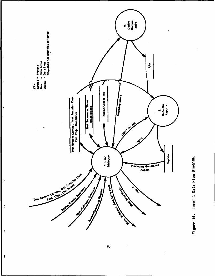
Overview. Figure 14 presents the Level 1 data flow diagram for ProductS. As shown, the three high level processes of Product 5 are User Dialogue,Derive Unique Jobs, and Generate Reports. Note that the process numberingscheme reflects the hierarchies of processes.
The single external sink and source is the user, not shown, butconceptually the farthest left element. Through User Dialog, Product 5collects data and forms three data stores. As shown, these stores are:Test system components/task function data/performance objectives/conditions;Task sequences/times/descriptions, and the Kaplan-Crooks (or whatevertaxonomy is used) taxonomy.
The Derive Unique Jobs process derives input from the Task sequences/times/description store. It provides output to the Jobs store. The processalso interacts directly with User Dialogue when detecting FeasibilityErrors, e.g., when the user enters constraints of time and distance whichaffect the construction of unique jobs.
The Generate Reports process accepts report requests from UserDialogue, extracts necessary information from various stores, generates therequested report, then either stores the report or returns it to the user(through User Dialogue) for review. Previously generated reports arereturned to User Dialogue directly without processing.
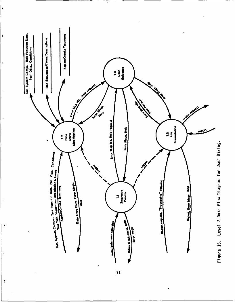
User Dialogue. All the functionality of User Dialogue is provided byR:BASE. Therefore all User Dialogue software will not be written fromscratch. Figure 15 presents the Level 2 data flow diagram for UserDialogue. The four processes involved in User Dialog are: SequenceControl, Data Entry/Modification, User Guidance, and InformationPresentation.
Sequence Control controls the sequencing of menus/submenus, ultimatelypassing control to Data Entry/Modification onto Information Presentation,depending upon the user's intention. It has direct interaction with UserGuidance for the display to users of help and errors related to menus andsubmenus.
The Data Entry/Modification process takes input from the user as shownand outputs to the three input data stores. It interacts directly with User
69
CL..
I
.5.
aa
0
CE
II'
w00 0
cU
;o..
700
gOR
000
'AU
r4 .00
cc-
00
(41
I-o
710
Guidance in the form of error messages and help requests related to dataentry or modification.
The Information Presentation process interacts with User Guidanceconcerning error and help messages. It also interacts with the user in thereport request sequence.
Derive Unique Jobs. Figure 16 presents the Level 2 data flow diagramfor Derive Unique Jobs. The processes involved are: Classify Tasks;Establish Precedence Relationships; Test Feasibility; and Assign Tasks toJobs.
Classify Tasks will group the tasks according to the way time is usedto specify required performance. Category 1 tasks are those operator taskswith performance objectives related to response time requirements (e.g.,time on target). Category 2 tasks are those maintenance tasks withperformance objectives related to maintaining a constant rate or frequencyof activity over some designated time period. Tasks with performanceobjectives related to maintaining constant activity over some designatedtime period (e.g., supervising monitoring, guarding) will be considered as"add-ons" to the operator or maintainer jobs most closely related. Thiscategorization is necessary because the way in which jobs are formed differsdepending on the type of performance objectives to be addressed.
Establish Precedence Relationships involves organizing and coding thetasks to reflect the sequence in which tasks must be completed in order toproperly achieve the performance objective. This relationship is necessaryfor Category 1 tasks only. This process will be accomplished by developinga precedence network that shows which tasks must be completed before a giventask can begin.
Test Feasibility determines the "critical path" through the network oftasks in order to determine whether or not the performance objective can beachieved given the task sequence and task times. If the critical path timeexceeds either the response time required (for operator tasks), the user isinformed that the performance objective can not be achieved and istransferred out of the job forming process so that either task times orsequence can be revised or the performance objective can be relaxed.
There are two types of tasks. Category 1 tasks are time-based,mission-oriented operator/field personnel tasks. These tasks must becompleted within a specified time. Category 2 tasks are output-based,maintainer tasks (e.g., inspect, remove) and can be aggregated intomaintenance ratios that are compared to the maintenance performance criteria(also in maintenance ratios). These tasks are performed continuously overtime and result in the production of some countable output (e.g., partsreplaced). A third task type, not covered in the current Product 1 taxonomybut nonetheless important are cognitive or monitoring tasks. These tasksare performed constantly, but do not result in measured output and includetasks such as surveillance, security, and supervision. These may beoperator or maintenance tasks.
72

z
UU
wz
w FA
0 0I -. a t
0
>. L.
Ia) 0
733
Job construction using Category 1 tasks will be accomplished usingBrook's algorithm. (A narrative description for this process excerpted fromthe concept paper for Phase 1 of this project as well as a listing ofFORTRAN code for the algorithm is presented in Appendix B. We will extractthose portions of this code that support Product 5, and translate them tothe "C" language of Product 5.) This process assumes 1) that tasks areordered according to the amount of time each controls in the precedencenetwork (i.e., the "critical path" time beginning with each activity), and2) that tasks are assigned to jobs such that the required response time orproduction rate is achieved.
Job construction using Category 2 tasks will be accomplished bymultiplying maintenance task times by their expected frequencies todetermine total time (over a specified time period) required for eachmaintenance task. Maintenance tasks at each maintenance level will besummed to determine total maintenance manpower requirements.
Tasks such as management/surveillance or other cognitive tasks areoverlayed on the jobs resulting from Category I and 2 tasks such that, tothe extent possible, they are combined with jobs that already exist.
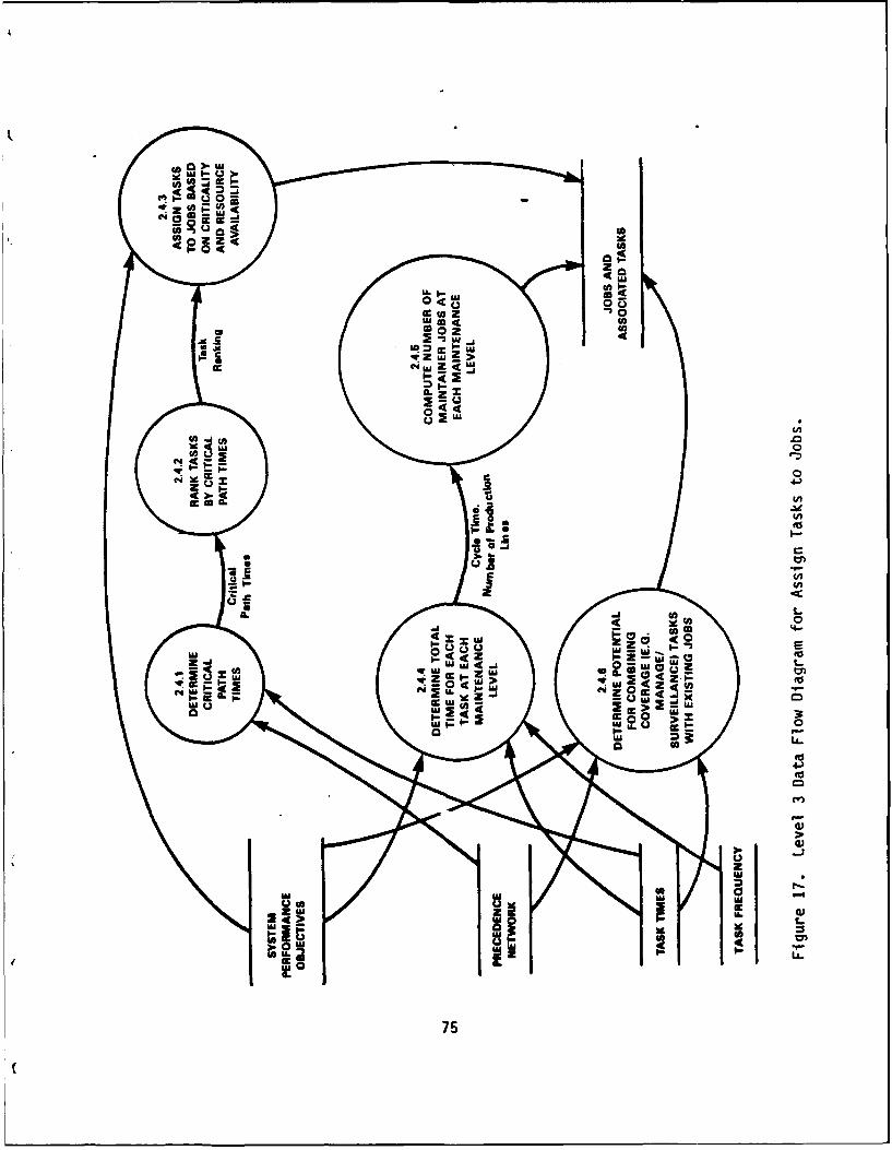
We felt that it was important to further define the "Assign Tasks toJobs" process in the Level 2 data flow diagram. Figure 17 presents theLevel 3 data flow diagram for this process. The Level 3 processes are:Determine Critical Path Times; Rank Tasks by Critical Path Times; AssignTasks to Jobs Based on Criticality and Resource Availability (Category 1jobs); Determine Total Time for Each Task at Each Maintenance Level, ComputeNumber of Maintainer Jobs at Each Level (Category 2); and DeterminePotential for Combining Coverage Tasks with Existing Jobs. The three datastores, System Performance Objectives, Precedence Network, and Task Times,all input to the formation of operator and maintainer jobs.
Generate/Print Reports. Much of the functionality of Generate Reportsis provided by R:BASE. Figure 18 presents the Level 2 data flow diagram forgenerate/print reports. The diagram includes one user-related process,select report type, and eight report-type processes. These report-typeprocesses are: operator functions, tasks, and times; operator tasksequences; operator functions data; operator jobs and tasks; maintenancecriteria; maintainer/subsystem/component data; maintainer component/taskdata, and maintainer jobs and tasks.
Structure Chart
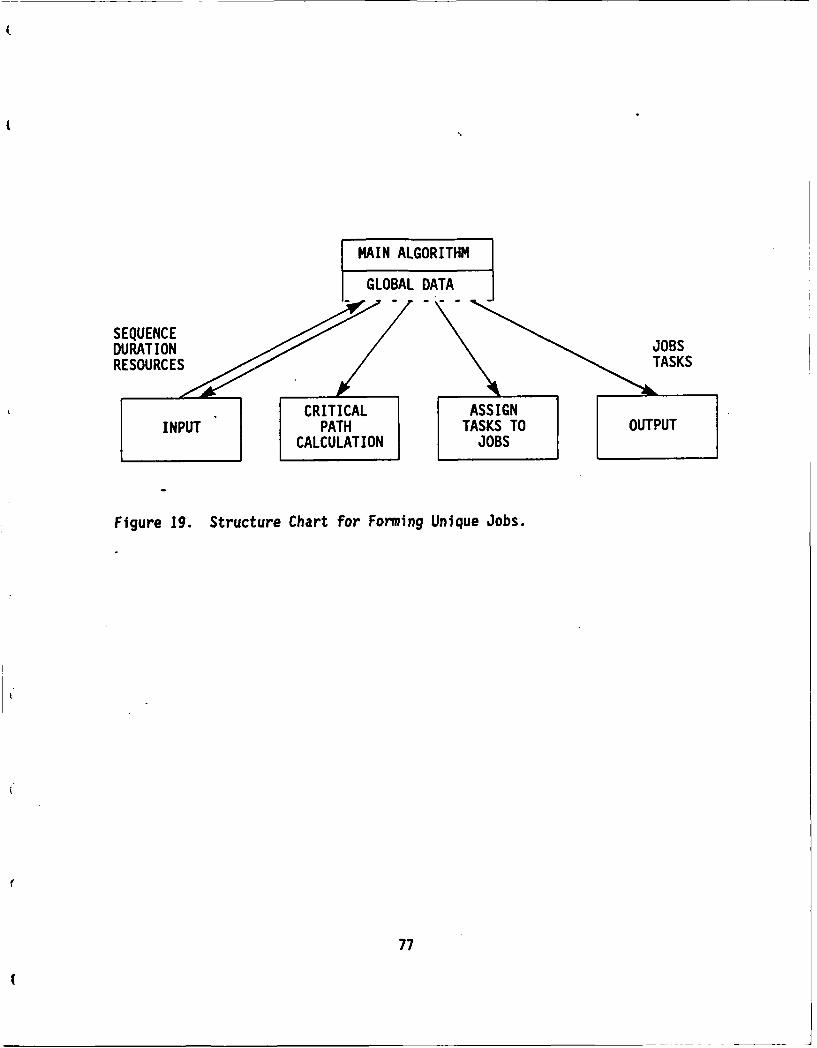
Figure 19 presents the structure chart for the algorithm used forforming unique jobs. The inputs to the algorithm are task sequence, tasktimes, and resource constraints. The algorithm calculates the criticalpath, that is, the path that traverses the network in the longest amount oftime. The path incorporates user-entered constraints about simultaneity andsingle/multiple operator requirements. Next the algorithm assigns tasks tojobs, using tasks within a function, then taking tasks from the next mostproximal function. The output is unique jobs and tasks with their times.
74
'A0
0 cc
-5 -
CAdzU
cLLL. go
to:) wI-- W
00uF-
cc-
9 0
C.) 0w 4c UAZ Z 2
w u - 0- Ux w"A, U
0l IL.-
UA Z 6 uj c z50 4

cU
'A 0
o C A
CC
r, 0 0
z a.0 cc
CCc
2.#.
C~ 06CL- a
o 'A
- C
CLc
C~cc
C 0
2~~ ON '
U00U
CL 0
LL.
'o dcC
762
MAIN ALGORITHM
GLOBAL DATA
SEQUENCE / "
DURATION ///\ JOBS
RESURES/ ,, .CRITICAL AS~SIG N AK
Figure 19. Structure Chart for Forming Unique Jobs.
77

We have considered two standard industrial engineering algorithms forthe operator manpower calculation for Product 5. They are the ResourceAllocation (RESALL) and Branch and Bound Assembly Line Balancing (BABALB)algorithms. We have decided to use the RESALL algorithm based on thefollowing.
The RESALL program in the "Balance" mode determines the minimum numberof jobs necessary to complete a category 1 (operator) function within agiven response time. RESALL in the "Allocate" mode determines the minimumamount of time in which a given number of resources (of various types - upto 20) can accomplish a function. In both cases, RESALL assigns specifictasks to resource units (jobs), but the model as currently constructed doesnot track the tasks assigned to each resource unit. The BABALB programdetermines the number of workstations necessary to accomplish a functiongiven a desired cycle time. However, this program assumes that cycles canoverlap such that each workstation may be working on a different cycle ofthe function. Consequently, the assignment of tasks to workstations givenby BABALB is appropriate for functions with "production" requirements (e.g.,maintenance tasks), but not those with "response time" requirements. Thetask assignments for response time (category 1, operator) tasks will have toaccomplished by modifying the RESALL program to compare the actual taskassignments to resource units. This approach will give a feasible solutionto the problem.
Integration of R:BASE System V
Product 5 is primarily an information-based application that requires arobust user-interface to ease use by analysts. As such, many of Product 5'srequirements can be achieved readily through the utilization of a commercialoff-the-shelf data base management system. Dr. Kaplan of ARI has encouragedthe contractor teams to use the same data base management system to promoteconsistent user interfaces among products. We have elected to use R:BASESystem V by Microrim, a data base management system chosen by othercontractor teams.
Many of the significant decisions regarding the approaches for developingProduct 5, as well as design implementation decisions for the operationalProduct 5, are directly related to the integration of R:BASE. A propersoftware solution for Product 5 (as well as other products) will integrateR:BASE application development and operational capabilities. The followingdiscussion overviews those capabilities of R:BASE which will be integratedinto the developmental and operational aspects of Product 5.
Application Development. R:BASE provides application development toolsto define menus/submenus, as well as forms for data base entry/modificationand report generation. These are implemented in separate programs thatinteractively guide the developer through definition dialogues, after whichR:BASE procedural language code may be generated. Subsequent modificationsto the generated code can be made either automatically (using theinteractive definition dialogue), or manually (to customize).
78
II
The application development tools of R:BASE will aid the development ofProduct 5 considerably. They will permit the rapid development of prototypeversions of Product 5 (with increasing functionality). This prototypingwill enable ARI to become more involved in Product 5 development byproviding recurrent feedback to developers as the implementation evolves.
Application Express is R:BASE's tool for creating menus, organizingthem into a tree of menus/submenus, and for associating actions (other thansubmenus) to menu options. These other actions include: entering,modifying, and displaying data using a form; printing a report; displaying ahelp screen; and invoking an R:BASE procedure or external language (e.g.,"C") program.
Menu options can be defined to be displayed both horizontally andvertically. Users make menu selections by moving the cursor direction keysor striking the number corresponding to the option (horizontal optionsonly), following by a carriage return.
Through Application Express, users also define data base records andtheir fields, as well as the types and precisions of fields.
Forms Express is R:BASE's tool for interactively defining forms usedfor data entry, deletion, or modification. Developers use a variety offunction keys that correspond to actions which enable forms to be "painted."
Permissible options (e.g., add, modify) are associated with the formduring form definition. The interactive dialogue prompts the developer tostipulate record attributes to be displayed, how they are to be sorted priorto being displayed, and conditions (attribute values) for selectingattribute values to be displayed. The conditions may be either hard-codedwith the form or user-specified (at run time).
R:BASE's tool through which developers interactively define reports isReports Express. As with the other application development tools,developers use a variety of function keys that correspond to actions whichenable (here) reports to be defined easily. R:BASE reports are comprisedof a number of reports sections (that are individually defined): the actualdata to be extracted from the data base; report/page/break headers; andreport/page/break footers. This variety of report sections enable complexand attractive reports to be interactively defined. Again, as with theother application development tools, the generated code can be manuallycustomized.
Operational Caoabilities. Through Forms Express, R:BASE provides avariety of mechanisms that will help to insure the integrity of dataprovided for entry/update to the underlying Product 5 data bases. Theseinclude testing 1) numeric data to be within a specified range, 2) characterdata to be of specified enumerated values, and 3) referential integrityagainst values in other tables. Other related R:BASE features will beused that define default values for fields and fields for which data
f must be filled, as well as double entry verification for data that areentered or modified. In addition, as data are displayed through a form,
79

users may move through instances of the single record type or extractionsfrom multiple records types (views) using function keys.
Forms are displayed with menu name at top, so that users maintain asense of "where they are." A status line is available at the bottom of aform screen for displaying messages relating to the success or failure ofuser-submitted operations.
R:BASE supports a rich set of 89 commands as part of its proceduralcommand language. Most significant of these is the variety of commands usedto navigate through and manipulate data in data bases. Further, R:BASEprovides a set of 70 math and string functions that are available in thecommand language. Errors resulting from command or function executions (onbehalf of users) can be trapped and acted upon (e.g., security violationslogged).
Data Base Security
For data base security, R:BASE supports the notion of a data base owner(i.e., superuser), with ability to assign read and modify passwords toindividual tables or views. Backup and load utilities are available forlogging data base files and reconsVtuting versions of the data bases.
In its newest release R:BASE provides a run-time, host languageinterface from the C programming language. This set of routines will beused in those portions of Product 5 that do not lend themselves to being.written in the R:base procedural command language. R:BASE also provides the"Filegateway" facility for importing/exporting data in a textualrepresentation to/from the underlying data bases.
The security mechanisms provided by R:BASE: USER PASSWORD, OWNERPASSWORD, READ PASSWORD, and MODIFY PASSWORD will be used to implementProduct 5 security. All users initiating use of Product 5 are prompted fora USER PASSWORD (see Figure 6), which makes that user known to R:BASE.System description data bases are created with OWNER PASSWORD equal to USERPASSWORD.
READ PASSWORD and MODIFY PASSWORD, rather, are explicitly establishedby system description data base definers (owners). These enable users toprotect their data bases (in their workareas) from unauthorized access byother users.
When a user specifies his or her intentions to use an existing database, a knowledge of whether he/she owns that data base is ascertained byR:BASE by comparing the USER PASSWORD to the OWNER PASSWORD of the targetdata base. Given the data base to be used is not owned by the user and theuser proceeds to attempt to read the data base, Product 5 will prompt forthe user to specify a READ PASSWORD to which the USER PASSWORD is thentemporarily assigned. R:BASE will then not not allow a user to readportions of the data base unless the USER PASSWORD is equal to the READPASSWORD established for the data base. The mechanism to protect otherusers from modifying a data base owned by a user is accomplished in a
80

analogous manner using the MODIFY PASSWORD. The utilization of READ/MODIFYenables owners to assign different READ/MODIFY PASSWORDs for each data base,as well the ability to modify existing READ/MODIFY PASSWORDs.
User Workareas
User workareas, run-time components of R:BASE System V, theKaplan/Crooks Taxonomy, and elements of the Product 5 application (e.g.,menus, forms) will be segregated to different directories in thehierarchical file system.
A "\users" directory will be established, beneath which a subdirectorywill be established for each user using his/her name (i.e., for user 1:"\users\'user I name'"; for user 2: "\users\'user 2 name'", etc.). Thisprovides a separate workarea for each user, beneath which furthersubdirectories are created to maintain data bases generated by separateProduct 5 "runs" for a specific user. These subdirectories are assigned thename of the data base prompted for by Product 5 when a new run is initiated.
C Within these subdirectories ("\users\'user name'\'data base name'\"),the actual R:BASE data base for a new run is maintained (1 System Type database), as well as all reports generated from that data base. By default,these reports are stored in file ames that identify the type of reportcontent (e.g., "oftt.rpt" corresponds to the "Operator Functions, Tasks, andTimes" report, although users may specify target files of their own choice.
R:BASE maintains information for a data base in three files: 1) the(actual) data base, 2) the data base structure, and 3) the indices. Onlythe actual data bases are maintained in separate user workareas. Filescontaining the data base structure and indices are shared by all users andmaintained in the directory containing elements of the Product 5application.
81
DATA BASE ANALYSIS/DESIGN
Data Base Entity Relationship Diagrams
Entity modeling (Teorey & Fry, 1982) has been used to formalize theanalysis of Product 5 data. This methodology employs entity relationshipdiagrams and entity definitions.
Entity relationship diagrams are used to graphically express therelationship between data objects. In these diagrams, data objects in thedata bases may take any of five relationships. These are one to one (1:1),one to many (1:M), many to one (M:1), many to many (M:M), or not related.Data objects not related are not connected with arrows. 1:1, 1:M, M:1, andM:M relationships are shown with arrows. A single arrowhead denotes the "1"side and a double arrowhead denotes the "M" side of relationships.
Product 5 data bases employ high-level entity relationship diagrams forthe Kaplan Crooks taxonomy (or whatever taxonomy is chosen) and Working/Derived Data. These two entity relationships, each one presented fromconceptual and implementation views, are presented in Figures 20-23,respectively.
Entity Definitions: The Data Dictionary
The.data dictionary is developed from the entity relationship diagrams,described above. The data dictionary is a listing in tabular form of allthe data elements in the data bases with a definition of the attributes andproperties (e.g., type, precision) of each.
Table 2 presents the data dictionary for Product 5. It contains fourcolumns: RECORD/Field Name; Type/Precision; Range; and, Unit of Measure.The RECORD/Field name is an abbreviated identification. The Product 5 database contains 32 records (names in all caps), each with associated fields ofthe records, 12 are associated with the taxonomy, the remainder withworking/derived data. The asterisk indicates a record type key (sometimescomposite keys), which uniquely identifies a record type instance. The"Type/Precision" indicates type I, F, or C, for integer, fixed, or characterstring. Precision of an integer indicates how many digits are required.Fixed are expressed as x:y, where x:y indicates digits to the right andleft, respectively. Precision of a character string indicates the number ofcharacters allowed. "Range" indicates allowed values. Product 5 "Units ofMeasure" are seconds, times per second, and percent.
82

TAX-CO FUNCIONTAS
1:M TAX-CONDITION-CAT 1:M
TAX-FUNCTION-TASK- TAX- EOUI PMENT-HI ERARCHYHIERARCHY-SEOUENCE
Figure 20. Kaplan-Crooks Taxonomy -Conceptual View.
83
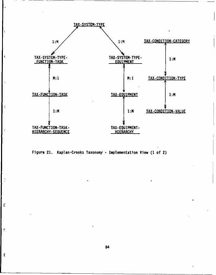
1M1:M TAX-CONDIT ON-CATEGORY
TAX-SYSTEM-TYPE- TAX-SYSTEM-TYPE- M
FUNCTI N-TASK_ OU1 4ENT
M: 1 M: 1 TAX-CONDITION-TYPE
TAX- FUNCTION-TASK TA-E UPMNT 1:M
1 :M 1:M TAX-CONDITION-VALUE
TAX-FUNCTION-TASK- TAX-EQUIP4ENT-HIERARCHY-SEQUENCE H..IERBARCHY......
Figure 21. Kaplan-Crooks Taxonomy -Implementation View (1 of 2)
84
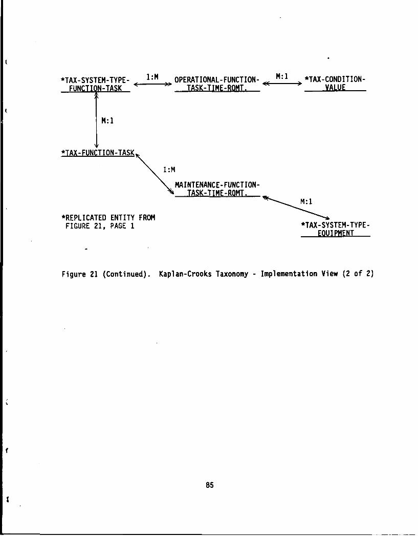
*TAX-.SYSTEM-.TYPE. 1:M OPERATIONAL-FUNCTION- -M:1 *TAX(.CONDITION.
FUNCTION-TASK TASK-TIME-ROMT. - VALUE
M: 1
*TAX.FUNCTION-TASK
1 :MMAINTENANCE- FUNCT ION-TASK-TIME-ROMT.
*REPLICATED ENTITY FROMM1
FIGURE 21, PAGE 1 *TAX-.SYSTEM.TYPE.EQUIPMENT
Figure 21 (Continued). Kaplan-Crooks Taxonomy -Implementation View (2 of 2)
85
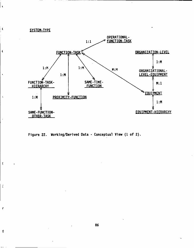
SYSTEM-TYPE
OPERAT IONAL -
1:1 FUNCTION-TASK
1:M 1:M1:M
ORGAN IZAT IONAL -1:i.LEY.LL-E)IPMENT
FUNCTION-TASK- SAME-TIME- N:1HIE BRCHY FUNCTION
U PM NT1:M PROXIMITY- FUNCTION
1:M
SAME-FUNCTION- EOUI PtENT-HI ERARCHYOTHER-TAK
Figure 22. Working/Derived Data -Conceptual View (1 of 2).
86
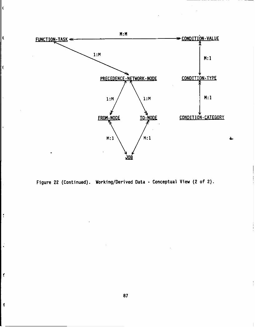
1M:M
MU:MO-TSK- -; COND)ITIO N-VALUE
MM:
PECONDITION-TYPE
M:
TO-NODE CONDITION-CATEGORY
m:I M:I 1
Figure 22 (Continued). Working/Derived Data - Conceptual View (2 of 2).
87

SYSTEM-TYPE
OPERATIONAL-
FUNCION-ASKORGANIZAI ION-LEVEL
1MMAINTENANCE- 1:M
FUNCTION-TASK--TAS
JiLBAMH !UIP-E MENT1-M IPMN
1:M PROXIMITY-FUNCTION
l:M
SAME- FUNCTION- EQUIPMENT-HI ERARCHYOTHER-TASK
Figure 23. Working/Derived Data -Implementation View (1 of 2).
88

MN: I
I N: 1
FROM-ODE T-NODECbiDITION-CATEGORY
Figure 23 (Continued). Working/Derived Data - Implementation View (2 of 2).
89

Table 2. Product 5 Entity Definitions.
RECORD/Field Name Type/Prec. R i U/M
TAX-SYSTEMTYPE* System type id 1/2 1-21 n/aSystem typename C/30 n/a n/a
TAX-SYSTEMTYPE-FUNCTIONTASK* System -type id 1/2 1-21 n/a* Func taskid 1/4 n/a
TAX-FUNCTION TASK* Func task id 1/4 n/a
Func-task-name C/30 n/a n/aFunc-task-type C/I OM n/a
TAX-FUNCTION TASK-HIERARCHY-SEQUENCE* Func task id 1/4 n/a* Child functask id 1/4 n/a
Task.sequence 1/2 n/a
TAX-SYSTEMTYPE-EQUIPMENT* System type id 1/2 1-21 n/a* Equipment_id 1/3 n/a
TAX-EQUIPMENT
* Equipment_id 1/3 n/a
Equipmentnm C/30 n/a n/aCriteria maint ratio F/3.2
TAX-EQUIPMENT-HIERARCHY* Equipment_id 1/3 n/a* Component_equipmentid 1/3 n/a
TAX-CONDITIONCATEGORY* Condition-category C/20 n/a n/a
TAX-CONDITION TYPE
* Condition type_id 1/3 n/a
Conditioncategory C/20 n/a n/aCondition type_name C/30 n/a n/a
90
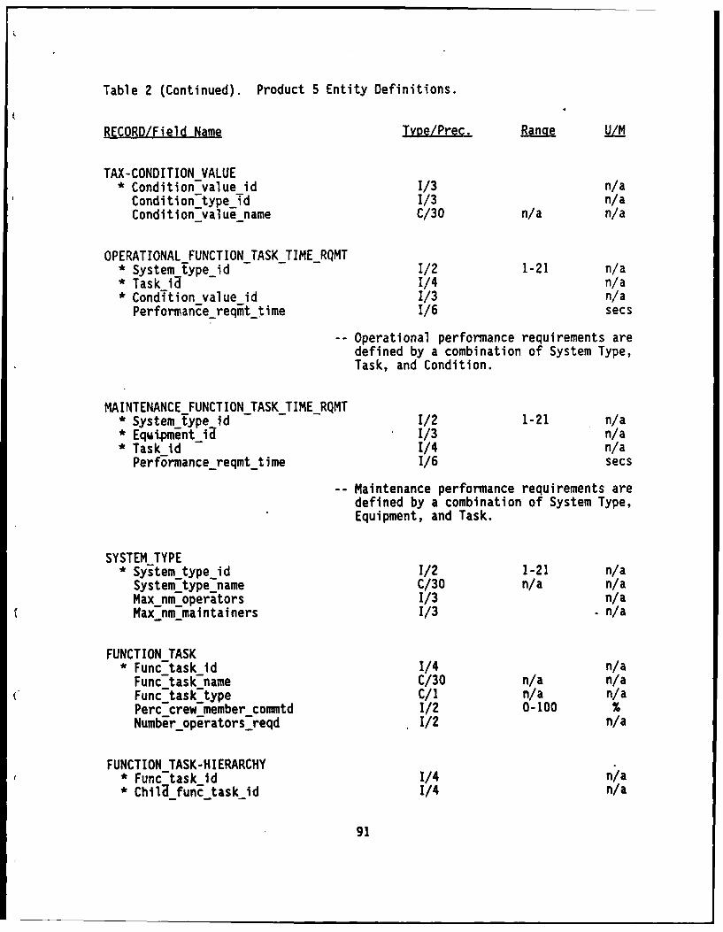
Table 2 (Continued). Product 5 Entity Definitions.
RECORD/Field Name Type/Prec. Range U/M
TAX-CONDITIONVALUE* Condition-value id 1/3 n/a
Condition typeTd 1/3 n/aCondition value name C/30 n/a n/a
OPERATIONALFUNCTIONTASKTIME_RQMT* System typeid 1/2 1-21 n/a* Task id 1/4 n/a* CondTtion value id 1/3 n/a
Perform ance_reqmt time 1/6 secs
-- Operational performance requirements aredefined by a combination of System Type,Task, and Condition.
MAINTENANCE FUNCTIONTASKTIME_RQMT* System type id 1/2 1-21 n/a* Equiment_id 1/3 n/a* Task id 1/4 n/aPerformancereqmt time 1/6 secs
-- Maintenance performance requirements aredefined by a combination of System Type,Equipment, and Task.
SYSTEMTYPE
* System typeid 1/2 1-21 n/a
System typename C/30 n/a n/aMaxnmoperators 1/3 n/aMax nm maintainers 1/3 . n/a
FUNCTIONTASK
* Func task id 1/4 n/a
Func-task-name C/30 n/a n/aFunc-task type C/I n/a n/aPerc crew member commtd 1/2 0-100 %Number operators reqd 1/2 n/a
FUNCTION TASK-HIERARCHY* Func task Id 1/4 n/a* Chilifun-ctask_Id 1/4 n/a
91

Table 2 (Continued). Product 5 Entity Definitions.
RECORD/Field Name Tyge/Prec.. Rangqe UL/i
SAME FUNCTION-OTHERjTASK* func task id -1/4 n/a* ChilU funZ task id 1/2 n/a* Same Tunc 5ther-task-id 1/4 n/a
Compi eted-before C/I Y,N n/aSame soldier C/I Y,N n/aDiffirent-soldier C/l Y,N n/a
PROXIMITYFUNCTION" FunciTd 1/4 n/a" Prox func id 1/4 n/a
Closeness-ranking 1./2 n/a
SAMlE TIMEFUNCTION" funcTd 1/4 n/a" Same-time func id 1/4 n/a
OPERATIONAL_-FUNCTIONTASK*Func taskid 1/4 n/aPerformanereqmtt ime 1/6 secsTask-time 1/6 sec s
ORGANIZATIONLEVEL*Organization-level C/30 n/a
ORGANIZATIONALLEVEL-EQUIPMENT* Organization level C/30 n/a
t* Equipmentid- 1/3 -,/a
EQUIPMENT*Equipment_Id 1/3 n/aEqul pment-nm C/30 n/a n/aQuantity 1/3 n/aCriteria-inaint ratio F/3.2
EQU IPMENT-H IERARCHY* EquIpment Id 1/3 n/a* Component equipmentlid 1/3 n/a
92
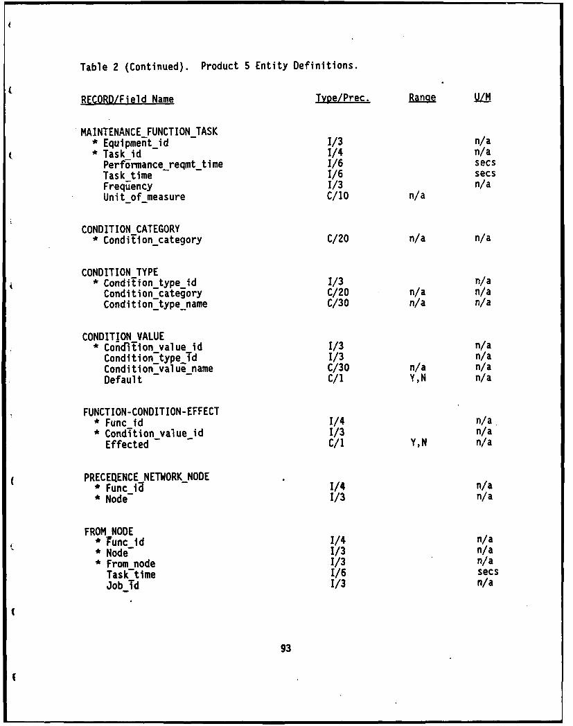
Table 2 (Continued). Product 5 Entity Definitions.
RECORD/Field Name Type/Prec. R U/M
MAINTENANCEJFUNCTIONTASK* Equipment_id 1/3 n/a* Task id 1/4 n/a
Performance-reqmt_time 1/6 secsTask-time 1/6 secsFrequency 1/3 n/aUnitof-measure C/1O n/a
CONDITIONCATEGORY* Conditioncategory C/20 n/a n/a
CONDITION TYPE* Conditiontype_id 1/3 n/aConditioncategory C/20 n/a n/aConditiontypename C/30 n/a n/a
CONDITION VALUE* Concfition value id 1/3 n/a
Condition -type Td 1/3 n/aConditionvalue name C/30 n/a n/aDefault - - C/i Y,N n/a
FUNCTION-CONDITION-EFFECT* Func id 1/4 n/a.* Condition value id 1/3 n/a
Effected C/I Y,N n/a
PRECEQENCE NETWORK-NODE* Func IQ 1/4 n/a* Node- 1/3 n/a
FROM NODE* Tunc id 1/4 n/a* Node- 1/3 n/a* From node 1/3 n/a
Task-time 1/6 secsJobTd 1/3 n/a
93
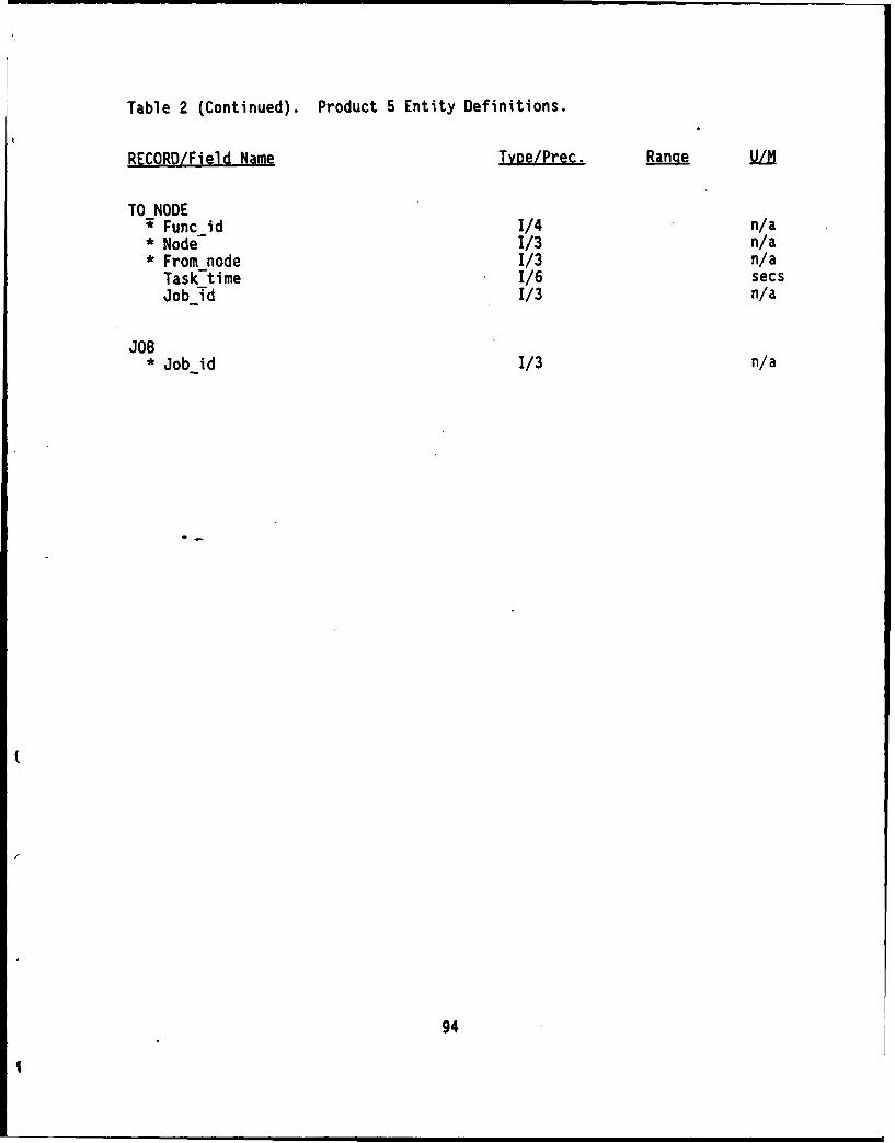
Table 2 (Continued). Product 5 Entity Definitions.
RECORD/Field Name Type/Prec. Ran e U/M
TO NODEFunc id 1/4 n/a
* Node 1/3 n/a* From node 1/3 n/a
Task-time 1/6 secsJob Td 1/3 n/a
JOB* Job id 1/3 n/a
94
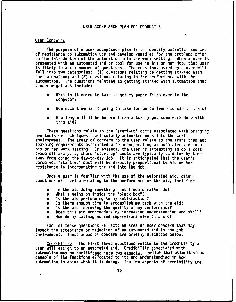
USER ACCEPTANCE PLAN FOR PRODUCT 5
User Concerns
The purpose of a user acceptance plan is to identify potential sourcesof resistance to automation use and develop remedies for the problems priorto the introduction of the automation into the work setting. When a user ispresented with an automated aid or tool for use in his or her job, that useris likely to ask a number of questions. The questions asked by a user willfall into two categories: (1) questions relating to getting started withthe automation; and (2) questions relating to the performance with theautomation. The questions relating to getting started with automation thata user might ask include:
e What is it going to take to get my paper files over to the
computer?
e How much time is it going to take for me to learn to use this aid?
* How long will it be before I can actually get some work done withthis aid?
These questions relate to the "start-up" costs associated with bringingnew tools or techniques, particularly automated ones into the workenvironMient. The areas of concern to the user relate to the transition andlearning requirements associated with incorporating an automated aid intohis or her work setting. In essence, the user is attempting to do a costtrade-off analysis, where "start-up" costs are typically paid for by timeaway from doing the day-to-day job. It is anticipated that the user'sperceived "start-up" cost will be directly proportional to his or herresistance to incorporating the aid into the job.
Once a user is familiar with the use of the automated aid, otherquestions will arise relating to the performance of the aid, including:
* Is the aid doing something that I would rather do?* What's going on inside the "black box"?* Is the aid performing to my satisfaction?* Is there enough time to accomplish my task with the aid?e Is the aid improving the quality of my performance?* Does this aid accommodate my increasing understanding and skill?9 How do my colleagues and supervisors view this aid?
Each of these questions reflects an area of user concern that mayimpact the acceptance or rejection of an automated aid in the jobenvironment. These areas of concern are briefly discussed below.
Credibility. The first three questions relate to the credibility auser will assign to an automated aid. Credibility associated withautomation may be partitioned into two aspects: belief that automation iscapable of the functions allocated to it; and understanding in howautomation is doing what it is doing. The two aspects of credibility are
95
associated with the allocation of functions to humans and automation and theuser-computer interface facets of automation design, respectively.
During the front-end analysis phase of automation design, functions areallocated to automation for performance. If functions are allocated toautomation that a user in the non-automated environment exerts control over,the credibility of automation performing such functions may influence theuser acceptance of the automation. In particular, functions that requireskill, judgment, or creativity may not be viewed by the user as credible ifassigned to automation. This user perception may be based on his or herdesire to retain control over the function or a perceived inadequacy ofautomation to perform the function. Regardless of the underlying reason,the result is a problem for the design developer in terms of gainingacceptance of the automation by the user.
The second aspect of credibility relates to the design of the user-computer interface. In particular, for automation to be credible to theuser, the user needs some understanding of how automation is accomplishingthe functions. Users cannot assign credibility of automation performance ifthe operation has the appearance of a "black box." The underlying issuehere concerns the user's need to evaluate performance of an automated aid.The amount of information needed for evaluation is directly proportional tothe expertise of the user, with the expert requiring the most and the novicerequiring the least.
Tbe-ease of use of an automated aid is also likely to influencecredibility assignment. If an automated aid is difficult to use thepotential for user resistance of the aid is increasing. For example, an aidwhich forces the user to adopt new and different methods for accomplishinghis or her task is likely to be resisted. Computer jargon is anotherexample where the designer is likely to meet with resistance on the part ofthe user by asking that the user adjust to new or different terminology.
Ouality of Job Performance. For an aid to gain user acceptance, theaid cannot be perceived as reducing the quality of the user's jobperformance. There are a number of ways in which the quality of jobperformance may be influenced by the introduction of an automated aid to thejob environment. Functions allocated by the designer may result in usertasks that are viewed as unacceptable tasks to the user. In such asituation user rejection of, the aid is likely. From a differentperspective, unreliable performance by automation may require extra time andeffort on the user's part to address the problems created; user acceptanceis likely to be low for the perceived source of the problem, the automation.
Exoertise Levels. There are two different types of expertise levelsthat should be considered in an attempt to gain user acceptance of anautomated aid. First, there is the range of expertise inherent in thetarget user group. Second, there is the changing skill level of anindividual user as he or she gains familiarity and proficiency with the useof the aid.
The concern about expertise level within the target user group focuseson the domain knowledge of users that the automated aid supports. When the
96

target user group is relatively homogeneous in their domain knowledge andskill levels, this concern is not a viable issue. On the other hand, if thetarget user group is heterogeneous, a potential problem exists. Theunderlying question facing an aid designer is "what level of proficiency inthe job performance should we assume a user will have?" The higher theproficiency assumed, the fewer users in a heterogeneous group of users willactually be able to benefit from the use of the aid in their workenvironment.
The second part of the expertise level issue concerns the manner inwhich the user is able to interact with an automated aid as he or she gainsexperience. Novice users are only novices for a brief period of time.Frequently, friendly interface designs are optimized for the novice user andbecome a source of frustration as the user transitions from novice toexperienced user. An automated aid which is designed solely for a noviceuser is only optimal for an environment where the aid does not become anintegrated part of an individual's job environment. Such a situation wouldbe characterized as a continually changing set of users who due to lack ofrepeated exposure do not transition beyond the novice stage of automated aiduse. User acceptance of an automated aid requires that the transitionalnature of user be accommodated unless the situation clearly indicates thatusers will not have repeated exposure or opportunities to use the aid.
Views of Colleagues and Suoervisors. While the acceptance of an aidis not likely to made solely on the basis of the opinion of others, opinionswill be. an influencing factor. Enthusiasm among colleagues, in particular,for an automated aid in the job environment will help to lead to acceptance.Proponency for automation in the work place is frequently driven from thetop-down. A top-down push for acceptance may work in the short term, buttends to be effective only while the proponent is in place; when theproponent leaves so does the enthusiasm.
The early involvement of the target users in the design and developmentprocess is one method for creating support for an automated aid. Users tendto view their involvement as an opportunity to achieve a positive influenceon the impending changes to their work setting. The development of userinterest groups serves as a mechanism for bringing the users into theprocess to benefit themselves as well as the automated design.
User Concerns and Product 5 Acceotance
To gain user acceptance of Product 5, it is important to identify thenature of the concerns discussed in the first section and their importanceto Product 5 users. The first step Is the identification of potentialProduct 5 users. When Identifying the users of Product 5, we shouldconsider that there may be two different sets of users. The most obviousset of users are those that will actually Interact with Product 5 in theprocess of estimating manpower requirements for a target system. Theconcerns of this first set of users are likely to be those identifiedearlier in the section. A second set of users are those that will use themanpower estimates generated by the first user group. These individuals are
97
likely to be concernedwith how the automation aids in arriving at themanpower estimate.
First Look for and at Users. Those users who are likely to directlyinteract with Product 5 in the process of estimating manpower requirementsare likely to be found within the Directorate of Combat Developments at thenumerous TRADOC schools.. Preliminary efforts have been made to locatepotential users at these locations. Specifically, contact has beenestablished with individuals at Fort Rucker and Fort Knox based on namesprovided by TRADOC Headquarters. The purpose of exploring contacts at thisstage of design is to begin to identify potential concerns for the useracceptance of Product 5. From our preliminary discussions with potentialusers a number of issues have surfaced that may influence the useracceptance of Product 5.
Individuals involved in manpower estimation are not likely to beprepared to devote an extensive amount of time transitioning to and learningto use an automated aid. One individual indicated that if he couldn'tlearn to use an aid in one day, he would be hesitant to use it. In termsof user acceptance, they are likely to balance the time required to learn touse the aid against the cost of time taken from their on-going job. Inaddition, at least some users will not be responsive to reading manuals,particularly lengthy ones, in order to learn to use the aid.
There is likely to be a heterogeneous population of user in respect toautomation experience. Some users may be experienced with automation,thoughiot necessarily from their Job in the manpower estimation domain.Other users may have little or no, automation experience. The designimperative of ease of use for Product 5 is on target for the potentialusers. There will be a need to accommodate the transitioni of users as theybecome increasingly familiar with the use of the aid.
The process of manpower estimation is characterized as a time-consumingand difficult process. In some cases, users may have a large amount of dataupon which to develop an estimate. In other cases, users may have sparsedata available to them for developing an estimate. It is likely that userswill be quite receptive to an aid that reduces the time consuming nature oftheir task.
Whether or not the target user group for Product 5 can be characterizedas homogeneous or heterogeneous is not known at this point. However, it isapparent that there is no formal training for the manpower estimationprocess. There are publications from TRADOC, Soldier Support Center, aswell as local expertise and possibly locally developed guidelines thatprovide the basis for on-the-job training. Attempts should be made early inPhase 3 of this effort to determine the range of domain knowledgerepresented in the potential user group of Product 5.
Brina the User into the Desian Process. In an attempt to maximize thepotential user acceptance of Product 5, users need to be brought into thedesign and development process. The beginning of Phase 3 of this effort isan optimum time to bring the user into the process. At such a time ourdesign and development process will be a sufficient point of maturity to
98

provide users with the design of the aid for their comment. Importantly,bringing the user in at that point will still enable user modifications tobecome incorporated into the actual aid.
The suggested vehicle for bringing the users into the process is a userinterest group. Currently, each school has a standing MANPRINT committee.While these committees do not necessarily contain those individuals who arelikely to be the users of Product 5, the DCD members of such committees arelikely in a position to identify the potential users. In addition, thereare undoubtedly members on MANPRINT committees who would be interested tolearn about Product 5 as potential users of Product 5 output.
The user interest group would have multiple objectives. One objectiveis to explain to users the purpose and proposed operation of the aid. Thesecond objective is to elicit from potential users an evaluation of theproposed aid and suggested remedies to shortfalls in the design orimprovements that may be made. The following topics should be addressed bydesign developers at a user interest group meeting:
0 The objective and purpose of Product 5* Potential benefits of using Product 50 How Product 5 works including data entry requirements0 Product 5 interface operatione How to judge the performance of Product 5* How Product 5 adapts to various skill and experience levels
Next, data should be elicited from the potential users on the followingissues:
0 User concerns related to transitioning from their current method ofmanpower estimation to the use of Product 5.
@ User concerns about the learning requirements associated withProduct 5.
Whether Product 5 will allow the users to perform the estimationprocess in a manner acceptable to them.
The quality of job performance and whether or not Product 5 isviewed as an asset.
e Potential problems with the use of Product 5 as designed.
* Suggested improvements of Product 5.
There are a variety of ways that opinions could be elicited during auser interest group session. A questionnaire could be given to participantsto insure that input is obtained from all interested members. The use of aquestionnaire would be advantageous in that brief demographic questionscould be included to differentiate comments of potential "hands-on" usersfrom users of the Product 5 output. The questionnaire method for elicitingopinions has the advantage of developing a written record of concerns andthe type of user raising the concerns.
99

Participants in the user interest group should be made aware of theimpact they have on Product 5 design and development. Some sort of follow-up, such as a memo to the interest group, is advised to inform the users ofactions taken on their concerns. In this way, bringing the users into thedesign and development process also means providing them with feedback tokeep them in the loop.
Members of the user interest group should include users from eachTRADOC school if possible. Accomplishing this objective might necessitatemeeting with subsets of the group at different times and locations. Thealternative of comprising an interest group from one to two schools couldhave the disadvantage of a lack of generalizability of the findings. Whilethere are likely similarities in the manpower estimation process across theschools there may be some differences due to the type of systems orequipment of concern at each school.
Cost and Benefits of User Interest Groups. Bringing users into thedesign and development process has costs associated with it. As evidencedby the tentative agenda for a user interest group, advanced preparation ofmaterials is necessary for the design developer team. Given the objectiveof eliciting input from all TRADOC schools, multiple user interest groupsmeeting would be a possible requirement. On the user side, there is a costin the time for attendance. The actual duration of a user interest groupmeeting can be reduced by the preparation of "read ahead" packages. A "readahead" package could contain: Product 5 description, possibly storyboardsto show interaction, design developer concerns for which user opinion isneeded, meeting objectives and agenda. The use of a "read ahead" packageoffers the attendees the opportunity to be prepared for the conference andfrequently increases the quality of a conference while reducing the timerequired.
The benefits of a user interest group directly impact the potentialuser acceptance of Product 5. Allowing users to evaluate the design priorto implementation offers the benefit of identifying potential problems whilethe problems may be readily corrected. Membership in user interest groupgives the user the opportunity to become part of the aid development team.By becoming part of the team the user has an investment in the ultimatesuccessful implementation of the automated aid-into his or her workenvironment.
100

REFERENCES
Bedworth, D.D. & Bailey, J.E. (1982). Inteorated productlion controlsystems. New York: Wiley.
Brooks, G.H. (unpublished, 1963). "Algorithm for Activity Scheduling toSatisfy Constraints on Resource Availability."
De Marco, T. (1978). Structured analysis and system specification. NewYork: Yourdon Press.
Kaplan, J.D. & Crooks, W.H. (1980). A conceot for developing humanperformance specifications. Aberdeen, MD: U.S. Army Human EngineeringLabs, Tech. Mem. 7-80.
Page-Jones, M. (1980). The practical guide to structured systems design.New York: Yourdon Press.
Siegel, A., Pfeiffer, M., Kopstein, F., Wilson, L., & Ozkaptan, H. (197).Human performance in continuous operations. Volume 1. Humanperformance guidelines. Army Research Institute Technical Report.DTIC #AD086131.
Teorey, T.J. & Fry, J.P. (1982). Design of data base structures.Englewood Cliffs, NJ:Prentice-Hall, Inc.
101

APPENDIX A
SUMMARY OF R:BASE INTERFACE
Overview
The selection of the R:BASE data base management system (DBMS) forProduct 5 directly constrains the nature of the Product 5 man-machineinterface (MMI). This appendix identifies the specific MMI features ofapplications built using the R:BASE DBMS. These MMI features include thenature of menus and forms, as well as the keystrokes (and their sequences)used in manipulating menus and forms.
The Application Development Tools of R:BASE
R:BASE provides several application development tools through whichusers interactively define menus, associate objects to menu options, anddefine forms.
APPLICATION EXPRESS is used to define menus and to associate one of thefollowing with each menu option (except "Exit"): 1) a form, 2) a lowerlevel menu, 3) a "non-form-based" data base query/update statement in theR:BASEquery language, 4) a report definition, or 5) an executable modulewritten in a foreign (non R:BASE) language (e.g., "C"). APPLICATION EXPRESSis also used to define the structure of all data base tables which form thebasis for the application.
FORMS EXPRESS is used to define forms, and is invoked by APPLICATIONEXPRESS when the developer conveys the intention to associate a form with amenu option.
These are robust development tools. An additional tool, REPORTSEXPRESS is used to interactively define reports. All these tools generate"programs" in the R:BASE command language, which may be customized (e.g.,through the insertion of additional statements in the R:BASE commandlanguage). A last step is required to compile the R:BASE commandapplication definition into an executable representation.
R:BASE provides the mechanisms for defining two flavors of menus,vertically and horizontally-arranged menu options. Figure A-i provides asample of each. The last option in all menus should be "Exit." Theselection of exit returns the user to the parent menu for all menu levelsexcept the highest menu, and escapes the Product 5 application altogether atthe main menu. R:BASE also enables the developer to optionally establish"[ESC]" with this menu "Exit" function.
For R:BASE menus with vertical options, the user selects an option byusing the cursor direction keys (e.g., "down arrow") or typing the option
A-I

R:BASE Vertical Menu
R:BASE Horizontal Menu
Figure A-1. R:BASE Vertical Menu and R:BASE Horizontal Menu.
A-2

number (immediate left of option), followed by a "[RETURN]." The developercan also define function keys-to be associated with menu options.
Note that menus have a menu title that is displayed on the menu aboveoptions (in the sample vertically-arranged options menu, "SalesInformation").
During menu definition, the developer can define help text to beassociated with a menu, which is available to the user at run-time throughthe selection of "[FlO]." For Product 5, this mechanism should be used todescribe in a few sentences the purpose of each menu option. R:BASE enablesthis help text to be up to 5 pages in length, but Product 5 should constrainit to a single page.
R:BASE Forms
R:BASE forms have the following characteristics:
1. Form fields require explicit user entry to add/modify. The notionof highlighting items for selection is not supported.
2. Forms can map to at most 5 data base tables.
3. Components (see Figure A-2):
a. Form title.
b. Operations menu at top of form (R:BASE terms these "menuoptions"). Generally, users first complete form fields withdata, and then select an operation from the top of the form(e.g., the equivalent of "insert," "update," etc.).
c. Prompts for data entry (e.g., "Salesman:").
d. Form fields (for data entry/display/modification) that areassociated with either table fields or with variables.
e. Status line which displays information about the completionstatus of data entry insertions/updates and field validation.
4. R:BASE supports the facility for expressing master-detailrelationships on forms, such that fields from many instances of thedetail record are displayed ("Transaction Detail" in Figure A-2)with a single instance of the master record to which they relate("Transaction" in Figure A-2). This mechanism provides theremaining two components of R:BASE forms, below.
a. "Tiers" which map to single instances of the detail record.
b. "Regions" which are composed of the tiers anoLthe detail recordheader line. There is-a constraint of one region/form.
A-3
( •
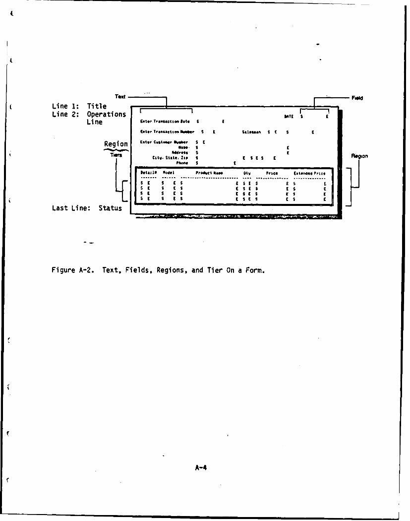
(Line 1: Title T e
Li ne 2: Operations DTLine Enter Transaction, late. £ E
Eniter Tranisact ion Nu~~er S E Salesman S C S E
Region Enter Ciistodier lueber N* S EE
Tir "dross S E Region
. . . . . . . . . . . . . . . . ....... ... ............. ... ......... ..Las Lie Status S
I .
S
S a S IS ES EA ES
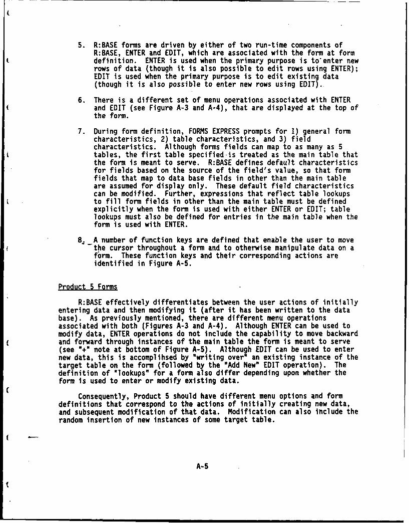
5. R:BASE forms are driven by either of two run-time components ofR:BASE, ENTER and EDIT, which are associated with the form at form
t definition. ENTER is used when the primary purpose is to'enter newrows of data (though it is also possible to edit rows using ENTER);EDIT is used when the primary purpose is to edit existing data(though it is also possible to enter new rows using EDIT).
6. There is a different set of menu operations associated with ENTERand EDIT (see Figure A-3 and A-4), that are displayed at the top ofthe form.
7. During form definition, FORMS EXPRESS prompts for 1) general formcharacteristics, 2) table characteristics, and 3) fieldcharacteristics. Although forms fields can map to as many as 5tables, the first table specified is treated as the main table thatthe form is meant to serve. R:BASE defines default characteristicsfor fields based on the source of the field's value, so that formfields that map to data base fields in other than the main tableare assumed for display only. These default field characteristicscan be modified. Further, expressions that reflect table lookupsto fill form fields in other than the main table must be definedexplicitly when the form is used with either ENTER or EDIT; tablelookups must also be defined for entries in the main table when theform is used with ENTER.
8. A number of function keys are defined that enable the user to movethe cursor throughout a form and to otherwise manipulate data on aform. These function keys and their corresponding actions areidentified in Figure A-5.
Product 5 Forms
R:BASE effectively differentiates between the user actions of initiallyentering data and then modifying it (after it has been written to the database). As previously mentioned, there are different menu operationsassociated with both (Figures A-3 and A-4). Although ENTER can be used tomodify data, ENTER operations do not include the capability to move backwardand forward through instances of the main table the form is meant to serve(see "+" note at bottom of Figure A-5). Although EDIT can be used to enternew data, this is accomplihsed by "writing over" an existing instance of thetarget table on the form (followed by the "Add New" EDIT operation). Thedefinition of "lookups" for a form also differ depending upon whether theform is used to enter or modify existing data.
Consequently, Product 5 should have different menu options and formdefinitions that correspond to the actions of initially creating new data,and subsequent modification of that data. Modification can also include therandom insertion of new instances of some target table.
A-S
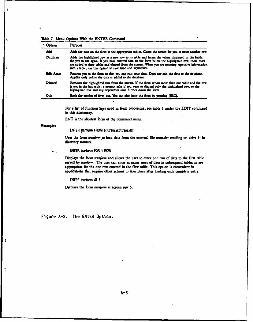
Table 7 Menu Options With the ENTER Command
Option Purpose
Add Adds the data on the form to the appropriate tables. Clean the screen for you to enter another row.
Duplicate Adds the highlighted row as a new row to its table and leaves the vWues displayed in the fidsfor you to use apin. If you have eneted data on the form below the highlighted row, those rowsae added to their tables and cleared from the screen. When you ae entering repetitive informationinto a table, use this option so saw time and keystrokes.
Edit Apin Renrm you to the form so that you can edit your data. Does sm add the data so the databaseApplies only bedmx the data is added to the dabase.
Discard Removes the highlighted row from the screen. If the form serves more than one table and the rowi not in the last table, a prompt asks if you want to discard only the highlighted row, or thehighlighted row sad any dependent sows further down the form.
Quit Ends the ssi of form use.'You can also leave the form by pressing [ESCI.
For a list of function Us used in form processing, see table 6 under the EDIT command
in this dictionary.
ENT is the short= form of the command name.
ExamplesENTER tranform FROM b:\trmnsact\transdat
Uses the form mrnon .to load data from the external file tvm.dar residing on drive b: indirectory vmsaat.
ENTER tmforn FOR 1 ROW
Displays the form mnmform and allows the user to enter one row of data to the first tableserved by mnform. The user can enter as many rows of data in subsequent tables as areappropriate for the one iw entered in the first tabie. This option is convenient inapplications that require other actions to take place after loading each complete entry.
ENTER tr'norm AT S
Displays the form winform at screen row S.
Figure A-3. The ENTER Option.
A-6
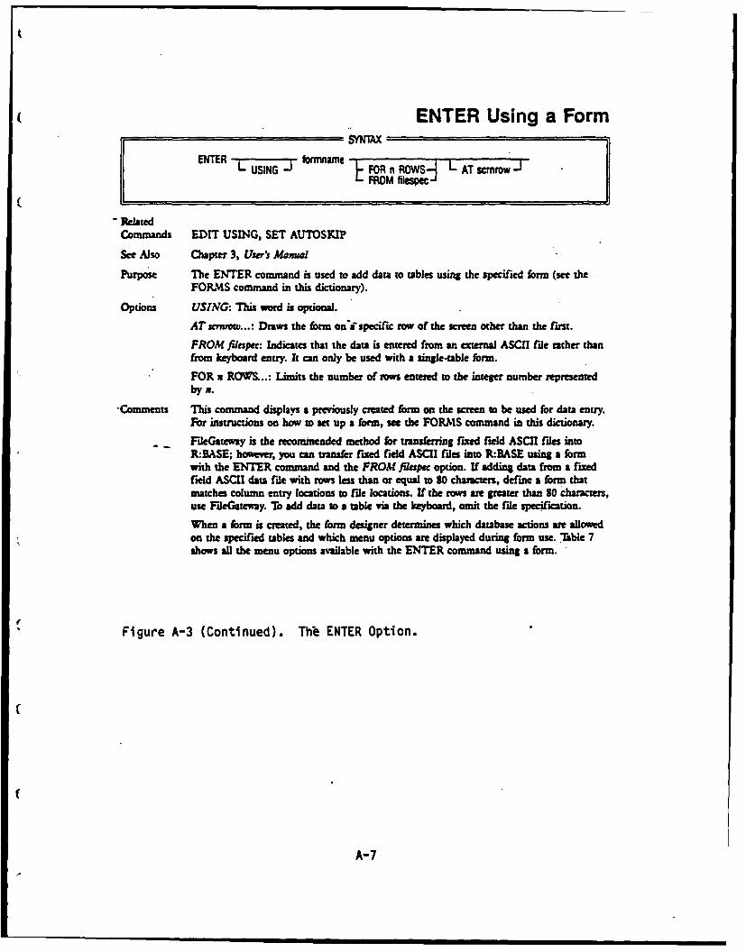
ENTER Using a FormSYNTAX
ENTER LUSING-J FOR n R0WS L AT scmw JFROM filespe J
- RelatedCommands EDIT USING, SET AUTOSKIP
See Also Chapter 3, Ur's Manfal
Purpose The ENTER command is used to add data to tables using the specified form (see theFORMS command in this dictionary).
Options USING: This wrd is optional.
AT scmwv...: Draws the form oniaspecific row of the screen other than the first.
FROM filapec: Indicates that the data is entered from an etermal ASCII file rather thanfrom keyboard entry. It can only be used with a single-table form.
FOR n ROWS...: Limits the number of rows entered to the integer number representedbyn.
-Comments This command displays a previously created form on the screen to be used for data entry.For instructions on how to set up a form, see the FOR S command in this dictionary.
FileGateway is the recommended method for transferring fixed field ASCII files intoR:BASE; however, you can transfer fixed field ASCII files into R:BASE using a formwith the ENTER command and the FROM fltipec option. If adding data from a fixedfield ASCII data file with rows less than or equal to So characters, define a form thatmatches column entry locations to rile locations. If the rows are greater than So charcters,use FideGateway. To add data to a table via the keyboard, omit the file specification.
When a form is created, the form designer determines which database actions are allowedon the specified tables and which menu options are displayed during form use. Table 7shows all the menu options available with the ENTER command using a form.
Figure A-3 (Continued). Thb ENTER Option.
A-7
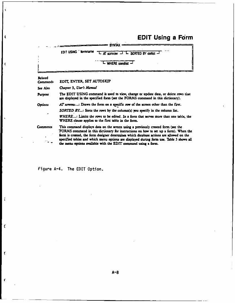
EDIT Using a Form
EDIT USING Irmname -L f r -J L SORTED BY collist J ...
" L WHERE condli -J
Related
Conmmands EDIT, ENTER, SET AUTOSKIP
See Also Chapter 3,. Usr's Mamal
Purpose The EDIT USING command is used to view, change or update data, or delete rows thatar displayed in the specified form (see the FORMS command in this dictionary).
Options ATsemow...: Draws the form on a specific ow of the screen other than the first.
SORTED BY...: Sorts the rw by the column(s) you specify in the column list.
WHERE...: Limits the rows to be edited. In a form that serves more than one table, theWHERE clause applies to the first table in the form.
Comments This command displays data on the screen using a previously created form (see the"FOgMS command in this dictionary for instructions on how to set up a form). When theform is created, the form designer determines which database actions are allowed on the
- specified tables and which menu options are displayed during form use. Table S shows allthe menu options available with the EDIT command using a form.
Figure A-4. The EDIT Option.
A-8
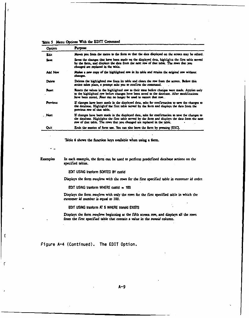
able 5 Menu Options With the EDIT Command
Option Purpose
Edit Mhoves 7 fron the menu to the form so that the dam displayed on the scrw may be edited.
Sa Sas the change that hs been made on the displayed data, highlights the first table srvdby the 6M nd dsplays the dam 1-or the m= tow of that table. The tows that youchanged ame replaced in the able.
Add NIiew Malm a mw copy of the highlighted row in in table and reains the original row without
Delete Deletes the highlighted tow from its table and de the row from the sceen. Before thisacuon W= pJae a prompt as .syu to cof'irm the command.
Re Resets the value in the highlighted mw to their state before chzge were made. Applies only"t the highlighted row before changes have been saved to the database. Ater modification.have ban strd, Rku can o longer be used to restore that tow..
Previous U change have been made in the displayed data, asks for confrmation to save the changes tthe database. Highlightf the fims table served by the form and displays the darn from thepmiom row of that table.
.. Net If change have been made in the displayed data, asks for confirmation to save the changes tothe database. Highlights the ust table served by the form and displays the data from the nextrow of that table. The rows that you changed ar replaced in the table.
Quit Ends the session of form use. You can also leave the form by prsing [ESCI.
Table 6 shows the function keys available when using a form.
Examples In each eample, the form can be used to perform predefined database actions on thespecified tables.
EDIT USING Wrar.form SORTED BY custid
Displays the form mnfonn with the rows for the lrn specified table in customer id order.
EDIT USING btrnform WHERE custid f 100
Displays the form tranform with only the rows for the fru specified table in which thecustomer id number is equal to 100.
EDIT USING rariform AT 5 WHERE trans EXISTS
Displays the form mmform beginning at the fifth screen row, and displays all the rowsfrom the firu specified table that contain a value in the transid column.
Figure A-4 (Continued). The EDIT Option.
A-9
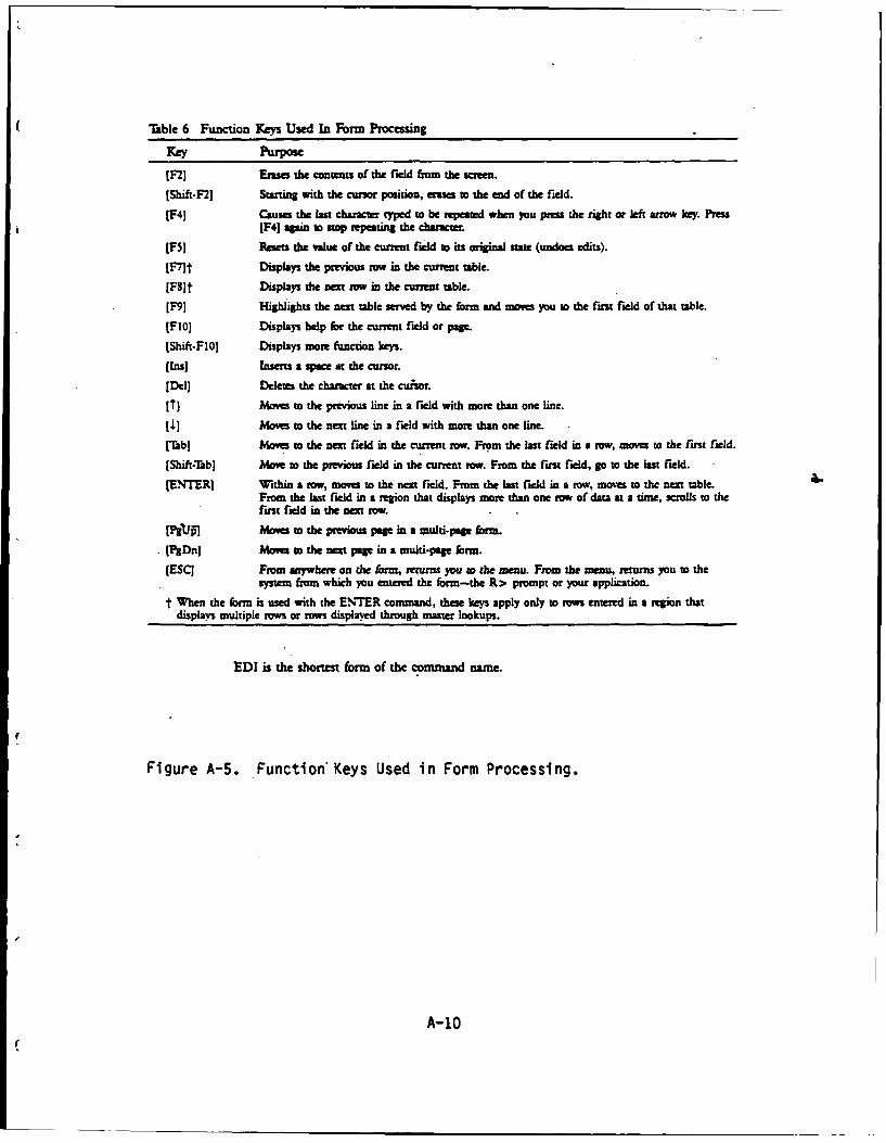
Table 6 Function Keys Used In Form Processing
Fey %rpose
[F2) Erases the contents of the field from the screen.
[Shift-F2] Starting with the cursor position, erases to the end of the field.
(4] Causes the las character typed to be repeated when you pIrs the right or left atmv key. PressPR] agpin to stop Mepating the chanicte
[FS] Resets the value of the current field to its original state (undoes edits).
[7t Displays the previous ow in the current table.
[FS]t Displays the nm raw in the current table.
[F9] lighlights the next table served by the form and moves you to the first field of that table.
[Flo] Displays help for the current field or page.
[Shift-F101 Displays more function keys.
[Ins] Inserts a space at the cursor.
[Del) Deletes the character at the cuiior.
[Tr Moves to the previous line in a field with more than one line.
[ Moves to the nexti inein a field with more than one line.
[Tab] Moves to the nest field in the current row. From the last field in a row, moves to the first field.
[Shift-Tab] Move to the previous field in the current row. From the first field, go to the last field.
[ENTER] Within a row, movs to the nest field. From the last field in a row, moer to the nert table.From the la.t field in a region that displays mor than one row of data at a time, scrolls to thefirst field in the nest row.
[PIITI~ Mows to the previous page in a multi-pae form.
* [PgDn] Moves to the nest page in a multi-pap form.
(ESC] From anywhere on the frm, returns you to the menu. From the menu, retums you as thesystem from which you entered the form-the R> prompt or your application.
t When the form is used with the ENTER command, these keys apply only to rowa entered in a region thatdisplays multiple rows or rows displayed through master lookups.
EDI is the shortest form of the command name.
Figure A-5. Function Keys Used in Form Processing.
A-10
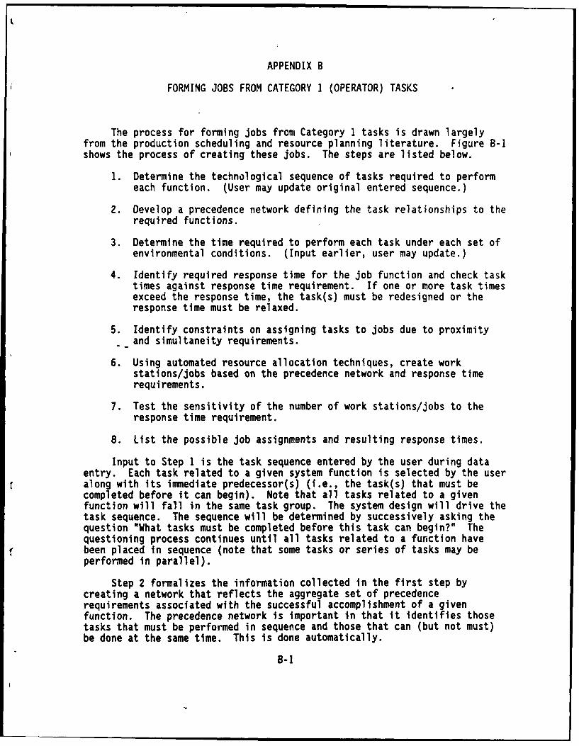
APPENDIX B
FORMING JOBS FROM CATEGORY 1 (OPERATOR) TASKS
The process for forming jobs from Category 1 tasks is drawn largelyfrom the production scheduling and resource planning literature. Figure B-ishows the process of creating these jobs. The steps are listed below.
1. Determine the technological sequence of tasks required to performeach function. (User may update original entered sequence.)
2. Develop a precedence network defining the task relationships to therequired functions.
3. Determine the time required to perform each task under each set ofenvironmental conditions. (Input earlier, user may update.)
4. Identify required response time for the job function and check tasktimes against response time requirement. If one or more task timesexceed the response time, the task(s) must be redesigned or theresponse time must be relaxed.
5. Identify constraints on assigning tasks to jobs due to proximityand simultaneity requirements.
6. Using automated resource allocation techniques, create workstations/jobs based on the precedence network and response timerequirements.
7. Test the sensitivity of the number of work stations/jobs to theresponse time requirement.
8. List the possible job assignments and resulting response times.
Input to Step 1 is the task sequence entered by the user during dataentry. Each task related to a given system function is selected by the useralong with its immediate predecessor(s) (i.e., the task(s) that must becompleted before it can begin). Note that all tasks related to a givenfunction will fall in the same task group. The system design will drive thetask sequence. The sequence will be determined by successively asking thequestion "What tasks must be completed before this task can begin?" Thequestioning process continues until all tasks related to a function havebeen placed in sequence (note that some tasks or series of tasks may beperformed in parallel).
Step 2 formalizes the information collected in the first step bycreating a network that reflects the aggregate set of precedencerequirements associated with the successful accomplishment of a givenfunction. The precedence network is important in that it identifies thosetasks that must be performed in sequence and those that can (but not must)be done at the same time. This is done automatically.
B-1
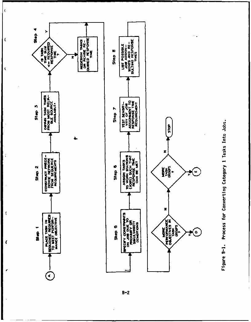
((
2 CL
bi5
~ F to
.j-.Iuicmn
WME
W 0
U
4J
1.0
B-2-
Step 3 assigns times to each of the tasks in the precedehce network.The method that Product 5 will use to identify and assign task times wasdiscussed earlier. An example of a precedence network (from Step 2) withtask times (from Step. 3) is shown in Figure B-2.
In Step 4, the response time requirement for the total job function isidentified for the specific set of tasks required to accomplish thefunction. Note that the achievable response time for a function cannot beless than the greatest sum of all sets of required tasks that must beperformed sequentially. If the sum of the task times for a required set ofsequential tasks exceeds the required response time, then the response timecannot be achieved regardless of the crew size. In this case, either theresponse time must be relaxed or the system must be redesigned to reduce thetime required to perform the tasks in the sequence.
Step 5 in the job forming process requires identification of anyconstraints that might affect the partitioning of tasks into jobs. Theseconstraints will restrict the formation of jobs and may arise due spatialconsiderations (i.e., distance between working areas in which tasks areperformed) or a requirement that two or more tasks occur simultaneously orin rapid succession. Tasks that cannot be combined into the same job willbe tagged to ensure that they are not combined. Another form of constraintis one that requires a set of tasks to be performed by the same person.Constraints of this type may cause tasks from different job tasks to becombined in the same job. The user will be asked if simultaneity orproximjtj constrains job function. The system default will be "no"constraints.
Step 6 of the process is at the heart of the job forming process. Theprocess makes use of a network analysis technique know as the critical pathmethod (CPM) or critical path scheduling (CPS). In the case of Category Itasks, the objective is to determine the number of jobs required to meet themission timeline requirements for completing all the tasks required tosuccessfully accomplish the function.
Step 6 is an iterative process through which tasks are assigned to agiven crew size such that the response time is minimized. If the minimumresponse time achievable with a given crew size is unacceptable (i.e., itfails to meet the system requirement), the crew size will be increased.This process will continue until the point where either the requirement ismet or further increases in crew size do not decrease the response time.This process is repeated for each job task containing Category 1 tasks. Ineach case, the minimum number of jobs that can still meet the requiredresponse times is determined. The largest of these minimum requirements isthe lower bound for jobs for the weapon system for Category I tasks. If anyof the functions must be carried out simultaneously, the number of jobs mustincrease to permit all of the required tasks to be completed within therequired time for all functions that must be completed together.
Several slightly different algorithms are available for implementingthe resource allocation process described above. Lang (1977) provides aheuristic approach for allocating a single type of resource to tasks in acritical path network. An algorithm for allocating multiple resources was
B-3

(7
3
4 2 Tak times
1982).
f
6-4
9 S 3 1

developed by Brooks (1963) and further extended by Bedworth (1973) andBedworth and Bailey (1982). Bedworth and Bailey (1982) provided a computercoded algorithm that implements the Brook's algorithm.
Brook's (1963) algorithm (BAG) was selected for use in Product 5 forassigning Category 1 tasks to jobs. The computer coded algorithm isavailable for use in Product 5. The steps required to assign tasks(activities) to jobs (resources) are as follows. For convenience, FigureB-3 gives a network and tabular results of these steps based on three jobs.
A. Develop the task network, identifying tasks and their requiredtimes.
B. Determine the maximum time each task controls through the networkon any one path. This is like calculating the critical-path timethrough the network assuming that the starting node for each taskbeing analyzed is the network starting node. This activity controltime will be designated ACTIM for convenience.
C. Rank these times in decreasing ACTIM sequence, as in Figure B-3 (G,A, C, etc.). ACTIM for task A is found by summing the times fortasks A, D, and E, to obtain'a total of 16. The rows titled TEARL,TSTART, TFIN, and TNOW are explained as follows:
1. TEARL is the earliest possible time, because of precedence andtime limitations, to schedule each task. The actual time willbe equal to or later than TEARL. TEARL equals the latest TFINtime for all immediate predecessor tasks.
2. TSTART is the actual start time of the task. If there were nojob limitations, TSTART would always equal TEARL.
3. TFIN is the completion time of each task. This equals thetasks TSTART added to the job-duration time.
4. TNOW is the time at which job assignments are now beingconsidered. Initially TNOW equals zero, but subsequently itequals the lowest TFIN time for all tasks currently beingworked on.
D. Sequence the tasks according to job constraints. TNOW is set atzero. The allowable tasks (ACT. ALLOW.) to be considered forscheduling at TNOW of zero are those tasks that would have acritical path method starting time of 0, namely tasks G, A, and C.These are placed in the ACT. ALLOW. row, sequenced in decreasingACTIM order. In this example, G, A, and C all have the same ACTIM,and so a secondary rule is needed. For this example we will chooselongest duration first, which dictates schedule G first. Anotherrule is needed for A and C, since both are five time-units long.Arbitrarily choose A before C. In the job-available column, thejobs initially available are placed--namely, three.
B-5
I

STEP A: Develop Task •,ree
Network Alncttis Dran Requird
STEP B: Determine A $Task Duration
d
C S
STEP C: Rank Tasks ,D
In Order of 4
Network G 16
Durations C Puldo
(ACTIM)
STEP D: Determine
Job Resources ActI'ft, G A C D 9 F E
Available (3)Duration 16 $ $ ? I
STEP E.F: Assign Tasks rAMTl 16 16 16 it 4 -
1"0 Jobs, One -.Rteoutcef required I I I I I I I 1.4Task at a 7EARL 0 0 0 5 $ 1Time In 0 0 0 . S 9 1 . -
Network Order 7
STEP G: Repeat zProcess TNOW u 15 2 22
Until Jobs Reucstavalable . 12r 276 10 r 0UneFormed , ACT ALLOW. SAC 08? F
are Foarm mmNo I 2 3 4
Figure B-3. Brooks Algorithm Applied to Allocation of Category 1 Tasks toMultiple Jobs.
B-6
i( ,
E. Determine if the first task in ACT. ALLOW., G, can be assigned. Itcan, since three jobs are available and G requires only one. Also,no predecessor limitations prevent G from beginning. G is removedfrom the ACT. ALLOW. list and the number of jobs available isdecreased by one to a value of two, since G required one job.TSTART for task G is set at the current TNOW and the TFIN is set aTSTART plus task G's duration time. Now it is necessary todetermine if task G being completed will allow another task to befeasible at some future time. With G it is not, since G is itselfan entire critical path. This same process is repeated for theremainder of ACT. ALLOW. tasks until the jobs available aredepleted. In this case, all task G, A, and C could be assigned aTSTART of zero. From the network of Figure 11 it is seen thatassigning task A allows task B to be scheduled a TEARL of fivetime-units later (task A's TFIN).. Similarly, tasks D and F can beassigned a TEARL that is the latest of A's and C's TFIN times.Note that if task A had required too many resources to allowassignment at TNOW of zero, we would still see if task C could beassigned.
F. TNOW is raised to the next TFIN time, which happens to be five, thecompletion times of both tasks A and C. The jobs available at TNOWof five is set to the number remaining after assigning resources atTNOW equal to zero (zero in this case), added to the number of jobsfreed because of task completion at the new TNOW (two in thiscase). ACT. ALLOW. we now set at those not assigned at theprevious TNOW (none in this case), added to those that have a TEARLequal to or less than TNOW (D, B, and F).
G. Repeat this assignment process until all tasks have been scheduled.The latest TFIN gives the response time that can be achieved withthe resources assigned--in this case, 17 time units. Three jobshave been scheduled.
Step 7 in the job forming process provides a means for investigatingalternative numbers of jobs and assessing the effect of these alternativeson the ability of the system to meet performance requirements. For example,a slight relaxation in the performance requirement might result in a needfor one less job. Conversely, by adding another job to a weapon system,system performance may increase dramatically. Systems designers and Armydecision makers need to be aware of such swings in both requirements andperformance in order to make rational design decision.
The product of this process will be a listing of the unique jobs thatresult from Category I tasks. With each job will be a listing of thespecific tasks associated with the job. Also, for each function consistingof Category 1 tasks, a resource profile will be shown that indicates whateach job is required to do, over what time period, and the proportion of thesoldier's time that is spent doing the tasks assigned to the Job.
B-7
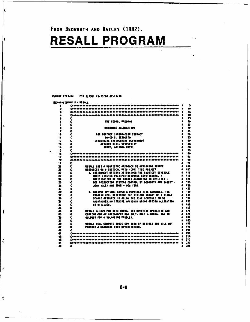
FROM BEDWORTH AND BAILEY (1982).
RESALL PROGRAM
&146 SL9I IN IW Plo" 3
2 C ......... a..............e...............S...O a 10
I# C FOR... F0.6. E INFORMATIO CONTACT A0666 6 so
61 C 36919 1. OORYN A 20
73 C IA*N STT25IESTYA 614 C TIE OM.Oh*TIII a 79s C a 45
16 C PU FURTHo"OooosooER ZUFPIATI CITIC? oooseooooo* so
II C 3*V13 SS AM NIIPIOAIf AI£N KAM21 C KSUIS 0 AITICA FAIXRI IPN*TYPPOJCT a 14223 1. 498 M OTPTION UIINIES I SWRTS 65II A i23 c UNE IMPLIZI-ESUI CNTRITS a 11
25 C 10646600*EE PRODUCTION SYST94 CONTROL IT KNORT01666646*0 AAU a 1226 C JN0.6e....a...es.AND $ONS -EN YRK.6e0.66066..06* a 13
I? C A f3
22 C 2. ANCUREU OPTION GIElN hKINK TIME31151 INE A 140
so C SUE IRESRET iLI-BES TIE SCewimIS.E 10O A ISO31 C E [email protected] TE COIT0KN ING OPTION ALLCAIO A611 1352 C 1J IILE IISUIETI a IN0
27 C a 143
29 C K 3061L VILL REMPTE INSIN CMTHE F115*011 MIN aO VILL T a I45
39 C PRR*H3* A11W*POC MINI OPTO OPTIMIZATION a I"s43 C A 2654 C KOOOOGS.. ILLIs OE Hosll 1111*1. LII 611111K P11*1161 *iieso a 295
40 C a 225
B-8

46 C INPUT SEOUIREINMTN, MINI CARD FORMATS, ME AS FOLLOSI: I 234
47 C CiM J REPRESENTS TYPE J. THERE IOU K MNO TON I CARD V * 235
48. C TYPES I AND I FOR THIS PROGRAM. 24049. C (ALL INTESER-FORNAT BATA IS RIGHT JUSTIFIES IN FIELD) 24550. C CARD I, COLS I - 72& FORNAT 2044, USER TITLE INFORMATION. 250S1. C CARD 2, COLS I - 10: TOTAL NURDER OF ACTIVITIES IN THE 25552. C PROJECT, DETUEEN 3 N 100 INCLUSIVE, 26053. C FORMAT FbO.O. 26554. C COLS It- 201 TOTAL NUMBER OF RESOURCE TYPES, 27035. C DETVEEN I AND 20 INCLUSIVE, F!O.0. 275$6. C COLS 21- 30: CRITICAL PATH TINE FROM CPR PROGRAM 28057. C RUN. IF 0. IS INPUT, CPR DATA VILL 23553. C IE COMPUTED. 290S9. C COLS If- 40: FIXED IZND2RECT) COST PER TIME PERIDS, 29560. C F2O.O. THIS MAY Of 0. FOR N0 COSTING. 3006f. C COLS 41- 501 STARTING TIRE FOR NORMAL SCHEDULE 30562. C (USUALLY 0.), F2O.O. 31063. C COL$ 31- 60: STARTING TIRE FOR OVERTIME SCHEDUL.E 325
64. C (USUALLY 0.), FIO.O. 32065. C COL 61: IF 0, INNIBITS DETAILED PRINTING FOR 32566. C EACH ITERATION. IF 1, 6IVES DETAILED 33067. C PRINTING. 33561. C COL 62o IF 0, INHIBITS PRINTING OF FINAL 34069. C RESOURCE PROFILES OYEN TIME. IF 1, 34570. C ALLOUS RESOURCE PROFILE PRINTING. 35071. z COLS 63- 67: IF 0, THIS IS ASSIGNMENT OPTION. IF 35572. C I., BALANCE - F.O. 36073. C COLS 68- 771 TINE REQUIRED FOR PROJECT BALANCE 36574. C RUN - F14.0. 37075. C 37576. C CARD 3, COLS. 1-32. FORNMAT 044, DESCRIPTION OF RESOURCE 33077. C - DOE CARD NEEDED FOR EACH RESOURCE - PUT IN SANE 38578. C SEQUENCE AS 6IVEN ON TIME AND COST CARDS 39079. C 395D0. C CARD 4, NORNAL RESOURCE QUANTITIES, 2014 FORMAT. RESOURCE 400
.11. C I IN COLS 1-4; RESOURCE 2 IN COLS 5-1 ETC. LEAVE 40512. C NON-USED RIGNT-JUSTIFIED RESOURCE 41033. C COLUMNS BLANK. 41504. C 42085. C CARD 5, OVERTIME RESOURCE QUANTITIES - SAME PROCESS AS 42566. C FOR CARD 4 - FORMAT IS 2014. 43067. C 435II. C CARD 6, NORMAL RESOURCE COSTS, 2014 - SWAN PROCESS ADS 44009. C FOR CANRD . THESE ARE DIRECT COSTS. 44590. C 4509. C CARD 7, OVERTINE RESOURCE COSTS, 2014 - SAME PROCESS AS 45592. C FOR CARD 4. THESE ARE DIRECT COSTS. 46093. C 46594. C CARD 6e , ACTIVITY CARDS - ONE PER ACTIVITY: 47095. C COLS I - 3 TAIL NODE NUNER, 13. 47596. C CUL$ 4 - 6: HEA NODE NUMBER, 13. 46097. C COLD 7 - 9 EARLIEST START TINE FOR ACTIVITY 4859. - NOT NEEDED IFRITICA. PATH 41699 C FOUND IN rNIS SUN. (13) A 495I O C COLt is- 12o DRArlo TIME FOR ACTIVITY, 13. a s0102 C CIL$ I- Is TOTAl. FLOAT FOR ACTIVITY, 13. NIT a 30512 C NEEDED IF RITICAL PATH FOUND IN & sil0 C THIS RUN. a Is
104 C CDLI It- W it FREE FLOAT FOR ACTIVITY, I. NIT a 320loo C NEEDED IF CRITICAL PAIN FOUND IN A 352I06 C THIS Eu. A SN107 C COI I9- 7S RESOURCE UNTITIES NEEDED FOI THIS a 5351"0 C ACTIVT, 2013. RESOURCE I IN COL8 a S4"I 19-21, RESOURCE 2 I1 COLI 22-24, a 541
226 C ETC. UNUSE0 eIfNr-JnrEinto a 51III C RESOURCES LEAVI, OLNiK. A uS
B-9
"(
112 C & 364its c ARTUIER SITU MY FOLLO. TO KAN CARS$ SIGNIFY LAST a $65114 C EUI A 70ItS C " txmtlE OF NICK 3T-P FOLLONS UlE#[ USER IES NOT a M .
116 C FUONSN BATA FROM CP 1U. 700 SCARCE RESOURCES AALYZERS mOIt? C $135Its C a 590I1I C KSLL ASSIGNMENT N - TEST. a 595120 C 5. 2. 0. 0. 0. 0.0 0. a 64121 C RESOURCE I a 45122 C RESOURCE 2 a 410123 C 2 4 A 615124 C 22 a 620125 C 25 30 & 625126 C40 44 4 430127 C1 2 0 0 0 2 2 3 4 3120 C 2 4 0 7 0 0 I 1 1 440129 C 1 3 0 O 0 2 at 6410 C 1 4 0)10 0 0 2 0 A 610131 C A S5132 C A 40
135 C,.....e..c.. s.4.6s4.ee.e*0*eS, eO* eO a 475136 C a 600137 C NSALL @AS COPILED I ASCII-FORTMI IN A UKIV6C - 1110. a 61sIeI C a 690119 Ceeaesiaos ese....sesO S Oeeses*9OeaeQll edsio0eee.i.sOs6***S*B*t 6eO6O e 4l 4 9
140 A * JOe ,ego e*o o Soog a 700141 Ceeoeeesoo oeeeoeeeeosaeee oeeeo e oeeeoaeeOo6ooooeo 4 7 5342 Coeoeeea..es~.ooee4oooB to~e6*es~eSo*eeoooo*eo *oOS*6*ooo@oeoo*o a I0
143 C POUNDS 00 RI*ILL PROLENS INCLUIe a ?l5144 C I. A NININUO OF 3 PROJECT ACTIVITIIS MD A 11411M OF 100. A 720145 C 2. AMININU OF I RESOURCE MI A MXNU OF 21. A 2144 C 3. ONLY I RESOUICE ALLOWED FOR A SALACE O . A ?30
- t47 C 4. 00 OVERTIME CONDITIONS ALLOVI FOe A $LANCE RUN. 7 n3149 Coooloeoe oeeeosoeesoeeooooeeeees eeeoeeoo6oeeeo oeooo A 745
IS| Ceoeoeeeeeoeoeeeeeeeeeeeeo eoo eeo ooeeoeeeeeee~esos..e.e oee.eeo AI 750
12 C A 740153 C NESALL VAS ORIGINALLT SEVELOPES I uICNAaI MASON, uORKIN ?63154 C VITN WIN KIUORTN, FIX PART IF TNE 5 R5SEAOCM PAPER A 77015s C TITLES AN ADAPIATIO OF TUE MN0KS ALSORITII FOR SCEEDULINI A 77S156 C PROJECTS UNDER MLTIPLE RESOURCE CONSTRAINTS - IDUSTRIAL a 730is7 C ENSINEERINS DEPART ET, ARIZONA STATE UNIVERSITY. TENPlsIV70 A 735ISO C 61SI Ef CaOMES AOi alirIuuS VERE RARE my "AVIP DEDUOOTH a 790119 C a 795140 Coooeo*..0a.*.o.o. eeee.oso.oo.e.ee...e.OaO.e.e.....eoeeo.*e .e.*ee ee A 0141 (..eeoe~~eo..eooOe...o*.eos oe..* oosa ooeeeoee~e~ee.eeeees A 0142 (SSSooSA.**o S*oo SS@*oeooeSoo SooSeoeOS*o**o.So*ooo6oo o **ioo*ooo.o*oe*4e A RIO16,1 €,ooo*s.*ee e..oooeosa..eo .eoeoe~e..o~e..s..e~ojo oo~s...~ m~eeoo a ilS144 CHARACIERe6 1113.1I2), OTITE2O.30) a sOZl145 DiREMSIUM 132(l0), TEIIPi100I, UP(IN0), P00122), U5E3122), 59(2 At 1166A 12), IPSOL(22), 801(22), 359(22), ITt100), INC100), IASSTIIOO), K A 3N167 251(20), 18E5420),, US|TM(20)0 LXN(IEUIO NROCEM200,20@, ICST0(20) a 335141 2, URC[II200,2Ol, IASFT(100), ITENP(l00) it 340149 COiNOi 14100), NOW0), IIIR(100), 154100), TF(10W), FF(I00), CPTu, A 041170 IS OR, IACI l11l1, ASRT(I0I, AS?100), tN(lOO,2O), nSES A 4371 IMTISE OVERT, SLAIN, RESI20II ORE120), CSIN2 I, CSTOI2O), T, N, a 355172 ES ISU IB TF, FFR AN NO172 IDT IURMIWt~ SVT/INU/, KAflIU / A 341174 C at 070
C 37 C0**REAiDI PSOJECT NAEII - $EWIED A IT176 C a to177 531*5 14,T TLE ( a 1s
8-10
16 IESO S40C FW11 P(01 O142,U142,V 2
1760 MOSTa 11366) 69
6M C006064EAD PaARETEU CARD-TITAL 1OAKS1 U ACTIVITIES, lulAL & m0
III C*0404TYPES OF RESOURCE$, CRITICAL FAIN TERMINATIONSATE a*1 905162 C****.FIIEI COST RATE, START TIM OF MOMA SCHEMIE. AND a 9149
613 Ce.seelaTl TIRE IF OVERTIME SCMIRULE. a 913114 c a "I9185 R1A0 13, ?ACT, 7ES.CPT1,F 11S11041, SOVER IPP,I,ALSIC4R aU 925m696 15 FORMAT 4A1.,1,50FO@ 920117 IF ITC.66)CALL E111 A 925M3 RACIsTACT A 940
119 14151 a 945196 6Tm4. a t5
192 £111.1 960
193 C a945194 Cessoe*EAD RESOURCE EAKIRS - ORNE REIUIRED/111NOCE A970
13 C A975
196 NS 20 IS.lUUS a To0
197 READ 25,fITI,J),Jul,5) a 935
its 20 CONTINUE a 990
lip 25 FORMAT 1536) a 995
206 C a 1000
201 C0eeSOREAD MNK APO OVERTIME RESOURCE 16ANTI1T1T CARDS, A Ills
232 C A IM1203 KEAI 36,11115(l),Is0,20) a Isis
204 Real 34,40usiEJ),JwI,20) a 1326203 36 FORMAT 12014) .6 1025
236 C a 1036207 C040"eSh u1011AL us3 OVERT IME RENUIC CUT CARDN. A 035
206 C a W64
209 NEAD 30,(CSII(J),J-1,24) A 1045210 READ 30,ICSTO(RIUu1,20) a 1030
211 NO 31 101.20 a 0553
212 1flS(II.RES1l A 060
-. 213 lions 41 18OREst1) a 1063
214 I1CSTIISCSTI'Il a 1676
215 K9CITII)eCSTSII) a 1075
216 is CONTIU a lse
217 C a foes
210 C..O@'INITIALIZI PERIOD RESOURCE fftIAs. a 1090
219 C a I95
220 NS 46 181,200 a 1160
221 No 4 Jul URIS a 1,49
222 INCEIIIJ148 a fi1l
223 40 "CE6I,JI.0 a IlsI
224 C a 1126
225 COSeeOREAD ACTIVITY CANIS-TAIL, 0E08, EARLIEST STAIT TIME, a I1.2
226 C..S@o3R&TIUI, TOTAL FLOAT# FREE FLOAT--ALL DETERMIINED 31 a 1130
227 cos"&e PREVIOUSS CPU aAWSvIS. A 1133
26 C a 1140229 W 45 I&sU.RACT A 1043
220 45 RE&l a0TI,()E13DRIFI)FII1NIJu.RS Alose
231 so FORMAT £2623) a 1151
232 C At It"0
223 C*e6002RZUT IMPUT IMWFATI 10a 1165
234 C A 1170
235 INFLAO&I a 1175236 IF 4CPT.[.#.) SO TO 3S a ties
227 INFLAG&S a Ill5
236 CALL CRITIC a it"o239 55 PRINT1 AS a It"5240 60 FORMA111 41001,21,6711111NI1 I [ TI M EIIOF-MASOM A9APfATIG1I OF DRO0lS A I2M
241 IRESOURCE ALOUITNI..iU,21,291TME BATA INPUT IS AS FGLLOSI./I/ a 1205
242 PRINT 45,ITLE A1230
243 AS FORMAT tl,21,4IPNJCT TZTL~s.13AA//) a 1215
B-11
(244 IF (INVLAO.1O.0) 60 T6 73 A 1226245 point ?0 a 1223244 70 FORMAT W/,UJSNCRITIC4L PATN "I3 FLOATS INPUT 11 USERS/I) a 1230247 Go To Is a 32.15246 75 PRINT OR A 1240249 Of FORMAT 6//,4X,42MCRIlTIC4L PAIN AIS FLU($S MIT INPUT IT USER .111) A 124530 Is PRINT 9O14Th a 6250251 90 FORMAT (11.49,26NNURA31 Of aCTlIFTESS11. oI 6255
ns 2" 91 M Pl~ 4I",41,2&NNE IF RESOURCE 111012.8110.01 A 1241254 PRINT 10OCt15p a We7255 360 FONT 111.41,19NCIITIC*L PATH6 ImuI6.0) * 1271256 PRINT 605,VIS a I230257 13 FORMAT 61/,4X.251U11E3 COST PER TIME *ITs,F0.93 A 201210 PR~it 11iiii a 12"5259 It$ FORAT W,41,26011TART TINE (NRMAL. SCNEDI.,F9.6) a I295240 PRINT 665,5061 a 13002A1 661 FORMAT Wi,41.26MITAT TINE (IVERTIME UCN)l.P9.0) A 1303242 IF (SALIC.87.0.) 0610 625 A 1310263 PINT 320 a Isis244 120 FUMNA U1,41,2MINIS 13 AM ALLOCATION RUN. a 1320261 so II is16 321266 125 PRINT 130,T0118 A 330247 130 FORMAT 4//.4X,4336TNIS 13 A SMANCING IN. TIRE IIIESTED IS1,FS.6) A 1333260 I35 PRINT 144 A 1340249 640 FORMAT 4/1,41,33NNRESIURCE INFORMATION 14AS FOL6Is~.J1 A 6341270 PRINT 141 4 1330271 141 VERMT 4/,4X,MNE3OMIC, 31,.6646UANT ITT, I91,bgCOST) A 1351272 PRINT Is* 4 1340273 150 FORMAT 621,13NONREN TITLE,30X1SUNag OVERTINE,9X,I5IORMAI. O A 113274 611511./.) A 6370275 N 155 Z.6,NRU A 1371274 15 PRINT A4.,RI(,3J15.t6I.33I,3NSSOI 1310277 W6 VENMT a4,33,*.21.z1,~,54,s ISI38275 PRINT 241 A 6390
-- 279 PRlNt 16 a 6395286 61 VENMT Wi/3N,21N*4CIIVITT INVORMATIO~s~n a 1400211 point 10 A 6401282 670 PORNT (/111I4NNT IFICAT ION, ,4JIfam..3,xNTgTa,21,4Nu3E3,2g A 1410233 61,I366RESIURCES REIUIpZI) A 1413284 P2IRT 675 A 6420
234 1 21 32 IS R4 3134 R& V 6 No RO O 366 36 2 313 114 35 116 A 1430267 2117 114 all 620./n A 1431236 N IN0 1.6 ,1ACT A 64402f9 110 PRINT A8,4)NISZUI)TFZVIRI,)J6 U 4645290 135 PORMNT 641,13,22,13,4X,13,31,13,3X,133,3,I ,914,uX,1114) a 6456291 IF IN*CT.T.3I 63 TO 9160 A 645292 C A 464293 Cosoeelg31 PUR RESTRICTIONS 0N RESOURCE DALIIICING 464294 C A 64762"5 IF (IA.g.6.. n3 to 695 A 6475294 IV INRES.671) 60 TO 940 A 6430297 IV 6CIPT3.3T.T11EI3 NO TO 950 A 6461
f2961 C 41490299 CoeoeOEKtER3Iu STARTING RESOURCE LEVEL - NIINUSR U T A3 CTIVITY 449300 C 46100
302 N 690 Iwl.N4C1 A 1310303 IF (10141,11.8T.154111 MSRaMII,I) a 6165
34 696COTIM00 a 520
r 30? Wits)oo. a 61531300 sn0666)oo A 6540360 1121111198l) 4 110
B-12
311 C 3511
it Csosselll FOR P20AICT FEASIBILIT. 3CTEhuZN if IE AloUIUIC is"1
113 C...e.6EWIIEINTU FE ANY ACTIVITY EXCEED TWIN AVAILABLE. * Isa314 C *1376
31% 95S H 2" NaI,113 A 1371116 266 PUL(NiulEs(mNI143 ) Is"8317 IS 205 5o. SACI ISIWSig so "s5 .slalli 13"
319 IF 400ia-N(I.J 77,20520 a INS5
326 I#1 CONIJME a 1664321 C a1401
1in C0.*0co"ITE "lm llmZlPAM 3V611 *3pIUosIN. 61616
323 C *1615324 So 216 J1*ACT 616,20
325 SUmuEl(I)47F(II 1625326 210 NBIPL(I)CPTD4S a 1630327 C a 4635329 gossommANK AC7Jvin at M I 1 *1 ORERO LOWOEST REuallhl P61N a 1640
329 Co..SSLENOTH, $NEAN TIES 31 MAlKING THE ACTIVIITY 01IN TIE A 1641
330 C06094LOUIEI DURhTION FIRST, & iaso
331 C is f51
332 211 Nauss$O a 166*333 NLI.IACl-I a 1661
334 N 240 131 ,.1 a 1670
331 IplaZ4I a 1475336 N 231 JEIPI,Ra4l a 160
37IF 4AAP(l)-ftSPL(J)) 225.22h,23 a 1aw333 220 IF so6166.I1(6 to1 231 6"3 gloat* 6nf
346 225 10 236 0I,00I a61?00341 114FL)AIaOI(. a 170342 IRhI,L68QN(J,L) 17a
S43 I30 II(JOLITEAPIL) 17115
344 30tomTIA lh, 1721
345 aOPl(IJ14Jp I Me
346 ARPI.jIJ30730-- 347 GO081442) 6 71
146 143)614j) 1746
349 1lj).sm? 61745
110 110116"tI 1714
31 NII)SOIJ) it ins
3S2 UIJ)amOt 6 1764
333 2011854l) a1765
314 tl1hlstJl f ill
311 [S1j641w A 1775
356 $011491104) a1710
117 IU6(I)SNUIIJI 1795
313 BUS(J)sSIIT I?"79
319 104taFFIIJ 1795
36" FF(I)OVF(J) is"83
361 FFIJ)*SSUT 6 365
362 STaIVII) a I31s
3u3 IF(II.Tffj) 6 'Its
364 TruJIs6At a 1320
341 31 CONIIWI A 1325
166 244 CONTIUE a 1IS0
16? IF IWage) 245,245,211 a 1833
us1 C A 1040
349 Co***Jil JAL it IUPUS6I 1U666E LOCAIONS. A 1341
36 9 a6310
171 245 PTIINaSPOSI A 19ll
372 IF 10411.41.0.0) piIIU50e3m a Is"
1V3 CER184.0 A I665376 ThNIGO, a 1970
s O75UT. a 6II53,6 la8loo. a is"0
3Sly*14 a Isi
8-13
379 OVERD.. 11914360 101=0. *190 1
382 CRON.. 1910383 1113.0. A 1915384 1114.104. A 1920385 T110. A 1925384 10313.0. A 1930387 1071.8. 6 935306 ISON1.0 a 1940389 90 SO J8,22 A 1945390 250 SPIJI.0. a If"0391 be 25 l01,11ACI a 1955392 ESI(I)SES(I) 4190393 ASllTlDmO. 4 945194 TENPIDOO. aIF?@39" 255 mUS(D.S. ao 1971394 C a It"0397 C0008CUIPUII THEl COST Of NORMAL. AN$ OVEITIN E SOUR~CES. a 965s3904 C*6000PR131 APPROPRIATE OUTPUT TIMLES. a 1990399 C a1995400 SO 240 10.10"hS 2040W0 CNOCIT(NISIN) A 2005
402 CS*CST0IIIO0MS(I A 2010403 ONT.0IT#CO a 2911484 148 ChST&COST*CO A 2020405 PRINT 245 A 2025404 265 P681*1 (lIIl A 20300? If 13*LC.01.0.) 60 TO 276 A 2035400 IF f1198.31.1) W TO 341 A 2040409 "lo3 71 A 2045410 a 160 " 2050411 270 PRINT 214 a 04515412 PRIII 285 A 2040413 271 F611*? (/,53,25141141 IS AN ALLOCATION RUN) A 2065414 280 FOIN1*1 /.S6,2NN16 If A #&LANCING OUR) 6 20704 13 265 F161*1 (1i/,41,9110VER111 RESOURCES ARE IF No BENEFIT IN3A *8.631 a 2071414 IWOI ANN. IF *N IVIRT1 QUDATITY VAS INPUT,/, 4X.&8N&Y THE 0513 11 A 208417 2 VILL K1 SET TO ZEN$1B I TIS PRO006*3 BEFORE 8*&*CIN.,//3 A 2065416 21" if (WUTI 303,305,29 A 2090419 295 Point ]S0 a 209420 30 16*3*? (391,17NOWIT131 ICNXI3 ,/) A 210421 60 10 325 A 2105422 305 9013? 310 A 2110423 310 FORHA1 41,1513MR1* SCKUL,/) A 2115424 IFI SAI.C.I.0.) AN To 321 A 2120425 PRINT 315,J1Es * a 112542& 31 13 R" 1/,0S,27N51481130 RESSICE LEVEL IS .13,64 UNITS) A 2130427 K11luTKlO A 2135423 PRINT 320,3819 A 2140429 32 FORNA1 (1,lS0,2641141011 TIME 1100151 11 ,14,1111 TINM WITS) A 2145430 SoT0340 a*2150431 325 PRINT 330 A 2155432 330 1613*? 1462,3539ER30II SOVRCEU COUND3I *33 CIITS,401 S31*1T,I) A 21"0433 PR13T U35 *t 2145434 33 11T (71,814C11VT3 4XOS01.5311011CE VAUhES) A 2170435 PRIN? 340 A 2171436 340 1613*? 421,1111189 ILIP,2X,116331 32 IS 14 IS 64 27 N I A 21M437 19 fil 111 112 113 114 215 Mid4117111 lt 112 IXD3 K A. A 1 204m8 2013*8 OWN6 TOTAL) A 2190439 345 SO 350 J4l.20 A 21"5440 3"0 INPOI P.OUL(J) a 220441 IF (F1P9.I.I so is 340 A 2201442 MINT 3S55(IPI0LIJ,J4I,2I) a 2210
C443 15 1113*? 121,111S111*1111?u tq2014,13)/) a 2211
B-14
444 C a*2m2445 Coo-CONIEP1 FIXED CUTS, AND IKE, NNWA, All OVER1111 A 222446 CooseSIEouCE C1111, 43B SUN TO FIND TRE TOTAL CBOT FER A A 2230441 C440.06IWEI TINE Pill@$. A 2235448 C a 2240449 3" SO 363 i..i,two A 2245410 IF (lAd? 451,453,365 A 2250431 363 N 380 l11 3 A 2255432 0111IZ)slES 11)*01E5 M-POOL (1) a 2260413 GlTMIM111t(13 A 2263454 IF 401) 375,3037t A 2270451 370 C31&C3101)*01 a 2275456 OVES.61111C07 A 2260457 SO I 380 A 22343 375 MoRISMII-UIEII) A 2290459 SPI1J.CSIII)SOU A 2M9460 SUPPOSUPP.P( I) A 2300461 330 CONTINUE A 2305462 CNORNOC037-SUPP a 2210463 IF CIACI-ICT) 385,305.390 A 2315464 385 IF (IFT-TINE) 57@,31@,3t0 a 2220
465 396 01s AXSP4NONOE 2325464 IF EBALNC.61.1.) 30 It0400 A 2320467 IF (IPPD.Nt.t) 68 TO 400 A 2335468 IF (NIUMI-20) 640,400,295 A 2340
46, C A 2345470 CosesoPIUI FOR THE CURRENT TINE PERIOD TIE RESOURCES COSUNE a 2250
471 Csses4683 COST 3411011 INFONAtIN. A 235472 C A*2340473 39" 02IN? 160 2361474 PRINT 24511 2370475 PRINT 340 a 2375476 KOVNT*G A 2360477 400 NO 415 j81,101l it 2383
473 IUSSIMU~SUERIj) a 2390-479 IF (091) 465,405,410 A 239540 405 NICEI'LJJIB1I613CJ) 2400461 60 to *15 6205
482 416 MACERILJsSISIJ) A 2410463 415 CoUIINUE a 2415464 ITINKsPTIM A 2420435 JINmL A 2425404 IF (BALIC.61.0.) 30 TO 420 A 2430417 IF 4IPPI.UE.11 60 TO 436 a 2425403 P2107 420.1IIE,(1USED(J),JUI,041s) A 2440409 420 FORAT Utj',,1
9 6s..S#.,2914) A 2445493 PRINT 42%,FIX,IUPP,CNORM,OUER,IOT A 2450491 425 FORNaT 4711,26NCOSTS FIR THIS PERIODla5F.0/ a 2455
492 MOUNTaNIU07#2 a 2440492 430 IFIIFIX+FII A, 6465494 TI3L~sTISLl*SUPf 24704953 INWT4NS*4CMDRN 2471496 TONER&TOIEl*OUEN A 2400497 TITAL@TGTAL*TOT A 2463490 NPP.0. A 2490499 CNISMNUO. A 2491500 31116..a 25015o1 161D.6 25051102 C a2510501 C.....0(T[RNINE If ANT ACTIVITIES MN AT IE END IF TNE 42511504 C84866CIIEIT TINE PERIOD. IF 30, PLACE TNEI11 6411CE11SlACE a 2meM0 csfsoeZMTo INS POOL.. a 3525
506 C 1 2520
107 N 4M I1IAACT a23"IS ITIMEUAIV1(l3-cIIU 2540109 IF 4TIIE-1T1K ) *50,431,450 A 2545
B-15

M) 435 IF (61F1C1)) 430,414,444 *2M5311 4463NO445 J0I,EUK A 255312 PO J)PL)4(J)A 2360$Is $4 CONTIUSE a 25635)4 414 ESNTIhhE 2576SI5 C 21755)6 Coesel[ITERRIUE If ANY ACTIVITIES AlE UCHEDULED 71 SIMT As 1 250sty osoe*TUE CHI OF TINE CURRENT TINE PERIOD. If S0, DETERINE a 251318 C$0...TME R013C IN UICH RESOURCES ARE TO If ALLOCATED. A 11905(9 CooeeenlUltT IS GIVEN 19 THE ACTIVITY 11I71 THE LONGEST a 2195520 C0004*O19MAZNIUG PATN LEISIN. IF THERE ARE INSUFFICIENT a 2444521 CS.O6eRESOURCE2, ILIP THE ACIIVITV ONE TINE UNIT FOR a 240S522 C4446011CONEATI11 1 IN TUEXT~l TIME PERIOD. a 2610523 C A 2615524 455 31 535 Im1,llC W 2120525 SI*~O. A 2625526 IF (TIUE-111(I)) 5,440,441 a 2630527 4 be3 470 .ianiRE3 A 2415520 FOlIJ)dPOGLIJ$-RN(IJ) A 2640529 11, (pmOOlJ) 465,470,470 A 2445510 465 14 4HUT.SN0RT.POL(J) a 2650531 410 CONTINUE A 265532 IF (SNORT) 475,520,520 a 2440533 475 to 464011K e USA 2665534 vsFI)4miO I) * 2670M2 40 POLaOIL (N)CRHloil(IN) A 267536 ESZ(11411l(I1.l. A 200
( 57 36 490 *uI,N0ES A 2685538 IF (W1111) 490,490,405 A 2690539 405 SP(NII)D. at 2695340 490 CONTINVE a270034) IF 63LNIC.9T.D.) SO TO 105 62705542 IF (IFFI.Nf.t1 00 O505 A 2710543 IF 4NOSNT-211 501,505,495 A 2715544 49" Fmint 500 A 2720545 500 FORNAT 521,26H4FO N[ HE 0YE FoilaINIIIII A... 0 6A 2725
- 46 ICTIVITY KLIP MEANS THAT THE FOLLOINIR 1ES0URCES VEEE CONSUMED DIII A 2730547 246INAT TINE PERIOD.,/,3X,10Hf2. WSERE ACTIVII IS LISTED UNDER ACT A 2725549 3Jul11 SLIP, 11 MEANS THAI ACTIVITY COULD NOT Of SCHEDULED IN THAI A 2740549 411K ,3,fWYERI0D BECAUSE OF a RESOURCE SHORTAGE. IHE RESOURCE C A 2745550 SAM K IDENTIFIED 21 A NEATIVE 904h?171.) a 275051 PRINT 265 A 275552 PRINT 340 a 2760553 10111.0 A 2765154 C A 2770553 Coto..PtiNT TIN ELISIDLE ACTIVITY THAT UAS KEEN SLIPPED ONE TO A 2775556 C$0646A LACK IF RESOURCES AND IDENTIFY THE RESOURCE SHORTAGES, a 270055? C A 2761so 5415 TIUEEplinfol. V"79559 RTTNlE.tva am795AO IfiT(iuTI) 2041561 IDOW.N) A 2045W62 350 JI.nimeD A 2010U63 5)0 IsF(JlaPIJl 2015564 If (D44.1CA.O..1 112 A m02us I65 W"P.011.11 a to 5314 a 2m2566 PRINT 515,ITYUE.I(i ),INC 11, 1IUP(N),U.(14,11E) A 2056 3 FONA 1033 1 2.l.I,1p3,31 -,1392414) a 335
me9 UTOSIO~ A 290
we0 9 A 28W0Sit CoeoCOsclHED)LE TU ACTIVITY, as THEN REmOV IT FMO FUURE A 2555W12 C664OCCONSIERAII61H. COUN ACTIVITIES SCUNEDE. COUTE a 20441173 COS44CURRENI LATEST PSO0ECI SKNLED PINION TINE. a 265371 C I 20701us1 520 AmSIII) IK a 201
B-16

576 RIFT (I 16FT1uE1#101 D *2800577 ESI(S1(1149999. A*2005
579 IACY.IACT41I A 2195566 IF 44IFYII'SFY) 530,530,525 a*2900
343 $43 CONTINug 21584 c * 29205O5 Cos*** TEST ACTIVITIES 10 SEE IF SLIPPAGE CAN Of 49somaca WITH a 29253 C00e6eFREE FLOAT, 1F 301, COMPUTE ACTIVITY KLAT, UNS THIN A 2930567 Coes.'ADJII ACCORDINBLY THE EARLIEST S7ANT TINE OF IHN A 2935560 C4060.ACTIVIrT AI TIE EARLIEST START FINE$ OF ANY IMMEDIATE A 29465e9 C.S0601PEN3ENT ACTIVITIES. A 2V45596 C A 2950591 10 5*0 IwlNACT a 29553592 IF (ESII)-ESIIII) 540,5U0.369 A 29*0593 540 9IFF.ESID-18dtb A 29*5594 If (FFII1-9IFF) 545,5*.6,5* a 2976395 545 I3UT-S1FF-FF(I) A 297359* KI6.(I a 290597 to 555 1~.NACT a 2965596 IF (Till-othAI 555,550,555 a 2996591 350 ES(151.L7A 295*00 555 CONTINUE a 36S"601 5*6 CONTINUE A 3061562 TIITINEI. a*361663 IF EIAT..6 PTINE*PTINE*I. A 3015* IF (IACT.UT.§) CONR'PTIME-TIME A 3020
*05 5*5 CONT INUE A 36256* IF 33ALNC.67.0.) 6 TO *05 a 303067 IF I1PPI.*E.1) 6o T6 575 A*3635*08 IF INOUNT.1.0) PRINT 500 a 3046649 IF (1181N-20)3596,196,575 ~'a 3045*30 S7s IF (DAA.C.IT.1 So TO 506 A 360*31 IF 4IPPI.NV 1) 6010 575 a 305
- 12 If (KOUIT.S' 0 PMINT 500 A 3000*13 It (NONT-lA) 590,596,575 A*3063614 575 PRINT 2*1 a 10706 15 SO1TO19o A 3075
617 M5 FRM 0 1*1 t0,111161IUCE FOR THIS ITERATION 1*6 SET AT ,11,714 UVI-05619 171.3 A 3090Alt 590 IF (OUT) 620,620,51% a 309*20 $95 PRINT 6 a 31*21 444 FORMAT If// a 310*22 Milli 300 a silo623 a1I163# A 3115*24 605 PRINT 2*5 a 3120625 PRINT 610,11.1 a INS5*2* 610 FORMAT (13"A,/1) A 3130*27 P11NT81 *5,KES1I3 a 3135*26 *15 FiliAT f/,0,IIE9dSOUOC1 FOR THIS I1E3AT1ON WAS SET AT ,139711 VNI A 310*29 179.) a 313610 60f0is 5m 3154*31 *20 MINT1 625 A311563*2 *25 fGlAA (/// *31*0613 MINT1 310 A 31*5634 630 MINT *33 A 3170*35 635 F66Atl (//,S6iI,9116*L P1IDAC? 90578,I1) a 3171
637 640 FOAN*1 (351,51713E3,IlI,4NILE,3,INOhAL,1,NOVIEIIINE,lN,NT6T A 3165Am6 IAL,1 a 31941639 MINT1 443, If 11, 1IL1,11f,TSWS, TOTAL a 3191646 *43 FORMAT (231,3Fl5.0) a 320
(643 mill m1a339
B-17

442 650 FOOM141/(i,331,Ma ETAILED SCHEME1 FOR THIS RUN 1S1hOER SI THE A 3210
643 1 nil OUTPUT PASS.) & 3295
644 c A 3220
642 Coese~PtIal PROJECT ACTIVITY SCHEDUL.E, UNICH CONSISTS OF A 43225
44 Csoos*LSTINIOF IN[T REVISED ACIIVITT PST AN$ FINISH TINES, A 3230
447 C a43231644 455 PRINT 245 A 3240
449 9KEmg3 a 3245
450 IF tool) 670,6701640 A 3250
(431 6"PRINT 6&3 &3255
652 465 FORMT /,1n, IOVEDTIME SCNESII.I) * 3240
453 so is 00 4 3245
654 670 PRINT 675 A 3270
455 675 FORMT W//29XISHUON4A. SCNESutE,/) 6 3275656 &so PRINT 455 a 320
457 405 FORMAT (/i,24X,26" PROJECT ACTIVITY SCHE3ULW,) 6 29
65s ICPTI*CPTs A 3290
459 PRINT 690,!CPTI A 3295440 4,0 FORMAT (191,30KCRITICA. PATH 1ERmIs1A ION RaYE.,W/) A 3300
63 PRINT 495 A 3305
662 495 FORMAT (134,OHT34ESE ARE TME REVISED START 0#1 FINISN,61 AIE~l . J31
463 PRINT 700 A 3315
664 700 FORMAT 1I,231,32N ACTIVITY START FINISH) a .5320
465 PRINT 705 A 3325
6"4 705 FORMAT 4201,IONYAIL HE4R.S%1SHEND OF PERIODWI/) a 3330
"?7 C it 333
640 C*****USE CRITIC SUIROUTINE TO REORDER ACTIVITIES A £340
669 C404eJPRIOR TO PRINTIHS THE FINAL SCHEIULE. A 3345
470 C A 3350
sitKEIT a 3355
472 CALL l. vi CRAI 3360
473 301;20 Ist,ACT A 3J45474 %Kk*KKR43 a 3370
475 IF 4NRK-53) 713,713,;10 43375474 710 PRINT 245 A 330
6 77 PRINT ?00 a ISI5673 PRINT 7053 3390479 KKNuSO 3395688 713 J71I)SIZ 1400
401 IH(I)SN(I) A 3405602 1615T41)RASST4I) A 3We
603 IASFT(I)@ASF741) A 343
404 720 PRINT 725.IT(I,,INl(,tiSS?(I),IASFT(lI a 3420
405 725 FORMAT t2QX,13,3N - ,13,71913.91.13) 6 3425
606 50 735 Is1,RL A 3430
407 IPIsI#1 A 3415
400 30 735 JaIP1,NACY A .3440
409 IF ITEMPMI-TENP(J) 730,735,73 A 3445490 730 SORTallAPII) A 3450
691 TEPII)STENPMJ a 3455
692 T[NP4J)wSORT A3440
in3 733 CONTINU 3445494 ZTEIPFtSuTEMP41) 43470
495 If (OUT.81.0.) IVERTPRITERPI31 41 347%494 PRINT 740,ITEMP0t) a 340
497 740 FOINAT (II,,3S,2111R1UM PROJECT DRARTION 1 3.I3N TIME WIN5) & 3405
490 IF (SKAT.0.) SO TO 790 a 3490
699 C a 34PS
700 CoeseTST 1S RETERIE IF TNE SCHEDULE JAST PRINTED 345 AN a 3500
?0f CoseosOVERTINE SCHEDULE. IF S0, ZERO IHE OVERTIME RESOURCE a 350
702 CssessA09 COST ARRAYS, AND [HEN REPEAT THE P20606N TO COMPUTE A 3310
703 C080.OTNE MORKI SCHEDULE. 41 35315
704 C a 3520705 745 IF (OUT) 705,M0,75 A 3525
704 750 it (DO.C.E.0.) W TO 75 A 3530707 NOUESLaKRES(3) a 335
B-18
70 god$(I) a JUED-OIED)I I I a540?Of J113-40ESE0) a 345710 755 No 760 ROG),NRES a 3350
?I ouso-o. a 355712 766 CDTQ(OI).0. a 3560711 765 30 770 iOmi,MACi a 3365714 770 ED(N0)SES0UO-0. a 3570735 60to I"5 63575716 775 Poiut 780 a 3560717 730 FONNAT (///.10X,99WPROJECI COULD 0107 It CORPLETED AS RESOURCES RED a 335711 WNlES EXCEEDED AVAILABLE RESOURCES ON WIE NEXT RUN.) A isle719 ofta 3595720 765 IF II*LOC.T.0.) Be TO 79m 3600721 60 TO Ito A 3605722 790 IF 1ITENP41).It.tREO) 60 TO 105 a 36)0723 so TO 745 a 3615724 7"5 KNWESL-KRED() A 3620725 PRINT go0 A 3625726 66 FOmANA 41/,501,17NIALANCE COMPLETE.) a 3630727 GO To0) IoA 3635723 sos IEt.ESI)0A 3640729 RRESII)NIES1)) a 3645730 So T0 763 A 3650731 C a 365732 C00*00PAINI RESOURCE UTILIZATION PROFILES A 36&0?33 c a 345734 610 Kai & 3670735 IF (INMs.uE.1)S O 30 as 3736 OTINE.JVZIE a 3600737 JTIIJIKN-I A3663736 vs5 PRINT #20,K A 3690739 620 FORNaT (I)HI,36,13SNNISOURCE &WDRt,2),WU~6,/ 3695740 PRINT 625, (BTIT(K,J),Jw1,3) a 370741 625 F011*? (20XI6NESOURCE ITEN 12,11,3"6 6 3705742 IF 11AiM.0'.o.) 00 iT 630 a 3716743 E1S1.N31Df4.KOmDK) A 3V15744 so7 3 isNi6 3720
-741 630 6167.0 A V372746 KREDEI.RKN1EDL a 3730P47 635 P2317 1 640KnEDI,KT@T a 3731740 04078016*71 2OZ,23110R1M. ouANTTi m 13,21,21 OVERT INS gMNIII A 3740749 1 IS.,13,2SN. 1011*1. AND OVJERTIME) A 3745no0 PRINT 045,XCSTPIX,KCDTOWK A 375075) 641 FORMAT (201,23HOORrAL COT/PERIS ID. ,13,201,2NOVERTINE COST/PER 6 3735752 91011,133/) 6 376071 PRINT m5 a 3765750 650 FORMal 532,23HUTILIZA1IOU 1FOaMAIUN,l, A 3770751 PRINT I5$ a 37757Y6 655 FORMAT 4231,SN NM6 DCHIDKiE,255,)7IOWIRTIM1E SCHEDME) 6 3760757 P2111 3S a 3765756 360 FORmat )14X,3H6UAM71TY1,6R.) E1CENT UTILIZATI6,?%,IN6UITIIIT,6X, a 3796759 119EPECEMIT UTILIZA71041 a 3795760 PRINT 65 A 36076) U65 FoRmal (151,4MTIME,71,0NVIE,71,22NG 1 2 30 1 3 6 ?19 10,91,4MV312 A 3665762 1,71,22140 1 2 3 4 3 6 7 6 9 t6,il a 3610763 N 670 matio as st764 370 LINI(U1sILAK a son9761 N 930 Lo2XNINI A 3021
767 AP. MCOLE 302)./1E(~IRSK .6 3766 Ns 875 Na28,177 3m4769 13 LINKUIIU.R so$64776 MFAW. A NH77) No 690 I.7#,PT a 3653in2 IF (L-IWRTP-l) 8600,0605 6a0amin M7 3 LIN)aWR1 6, 3065
B-19
774 a To IS a 11070771 #60 IFLA6.I a 367776 19" COITIN A 3604777 L~wL-% a $08s776 If INFLA) 91,895,903 6 3S90779 I" POINT 0,LCEL,,LIEIISI9)NCOL),LE(,1 a 369576 I'm: a 390
73 u to4 PI A3910763 965 PRINT 0LEE(,)(L1I,2.43II(Z)I7,1 a 3911
4.764 PIS FIT Iz1,13,61,13,6322111,201,22A1) a 392076 919 DO 1 20 Nm2,JPT 6 3925m3 920 LZNE(N)SILAIE1 A 3930767 N 921 MBP7@JT a 3371m2 L111(I)aBLANS a 3940769 930 C061IN 14 a 394579I PRINT P35 A 3956"13 935 FORhAT IiI,63911PARTIIL OVEUTI1E UTILIZATION ASSUMED NORNAL GUJAN A 395579 ITITIEI U66,i,561,72FULLY DEPOS OVER71NE FOR COllINS. FOR EXAPPL A 3960793 2X, IF TN[ OVERTIME IUANTITY,/,3SX,6"(INNAL AND OVERTIME) 13 2 AN A 3965714 33 NLUT I WIT IS U&, THEM THE,/,381,3NOTILZZAIION COST IS NO~MA A 397079s 4L N11111H IKE cost is ZERO.) A3975796 K-41a 3960797 IF INKS..613 60 1661!1a 3965"I6 6616s A 3996799 940 PRINT 945 a 3995Iff 945 FORAT CtM,2Z,73NO N0 AMC AS MUNSIR IF ESURCE TYPES 1S GREATI A 4000Sol It THIAN I - RUN TERMINATED) a 4005002 To165 A401t003 950 PRINT 955 a 4015604 955 P016*1 4IN,21,721110 DALANCE A$ TINE 6E6611 18 LESS THAY CUITICA a 4020Its IL FATH TERINATION DATE) A 4625666 60TOS 3a 4030It? 960 PRINT 965 a 403500e 965 FORNAT 41110,21,7914A RN CANNOT Kl NASE AS NE SURGED OF ACTIVITIIE6 4040lo9 1 16 LISI TIAN A 811611141 THREE.) A 40410161 fTo*4650Ito INS A 055612 UUIUTINE CRTI1C S813 DIMINSION 1400), LSII 0, 4J(160) 10
614 COMhh T(100), Nit"0), 6434100), 114160). 114100), FF110), CPTI, IsIts IINOIN, NACT, REMY1, *S111 30), &IFT1I6O), 101410f,2), ROSS 26636 1611616 TACT, 1, N, IF, F!, ED, OUS, I 25all KAL4 LU, ii 3Ns6 C see CPU UIORWJTIE To FINS OUTi CRITICAL PATH 35SI, C 406on C soe T*CTsf1T4. MURDER OF ACTIVTIES. 45621 C *so INGRSTANT TINE POR PROJECT. s622 C eas T1)TA1L NODE NVAIN R ACTIVITY 1. 55623 C *so 1413.11*1 m631 N4113E;14))T41). do124 C see 0U(I)*DURAIIOI TINE OF ACIVITY 1. 656w C see CPTP*CRZIC* PAIN TINE 70026 C *so l6CI)SIARLIEST 21441 TINE FE ACTIVITY 1. 75NY7 C 0e0 IFII)ul*3LIESI FINIUN TIRE FER I. of62s C $09 L541)wLATfSI STAT TIRE FEI 1. 65
629 C see LF(I)SLAIESI PINISM TINE PEE. Soof0 C so* 1711)0T6141. FLOAT FIR AC71VIII 1. 96"I C see PPI).PKE FLOAT FER 1. in63 C see AvIII13.1CHEIULE START FOR ACTIVITY 1. 445633 C see AIFT(1)ImlE3U FINIIN FER ACTIVITY 1. Ito654 C 136as C 126636 C *so ClICK 111161U DATA 13637 C ISO6w6 TACTo6aC I35639 SO 3 13,TaCI 340we0 IF 4NI141 ))Iil U is 125 :4
B-20

641 5 COITINE
3 C *sB P636*11 1 00~IS6 TAIL AnKS. I"o644 C 16383 IUIACT-1 170
646 SO 25 1.ISII 173647 11.1.1 ISO346 If IF (T1141..7CMD) 60 TI In 6849 60 13 LaI,NRES 19,654 1 11P*61132,L) Ill
95W 41(61,L).64N1,L) NO0652 1S NOhh.6111MII 335853 JIB? (N1) 210934 JASNIWNI 213933 .AINJ4I) 220656 Ac245s1(NK) 225#37 alwaUPI(s) 230
139 NIZsI)24646046N)33U 245661 ASITdOX:MASSY(m) 254042 AIFT(I1).ASFY(N) 25663 T(N)aJT 2"03M4 st*)OJA 265063 lilt)SJI 270I"6 ASSIMO&C 215S6O AUirEAS 2361168 26 ISSIZ.W us669 IF 441.87.76CT) N6TO 25 N9OM 0 lTo 10 295us1 25 CONTINUE 3I.67? C 30567s C ess SE6C013ATI 5011 IN NEAR NSE. 3WO
674 C IRus gleTACT-1 2076 go 041.1,1 325417 110401 330on 30 IF ITM1.IE.T(Oll N TV654uIn9 IF a63.TN46)6 TI SO 346
in 16o45 345as1 33 J.116111)3306 JPuNIIU) 333NI AZOASITII) 360364 AluallfTil) 365
my ASST(glease6lof ias A651(K)GANIMUI 231169 11491118.1 39
"IW AGSIII)MAN 40
692 AIUTigasa "a946P3 3644 Lot,663 4186194 ZIINNIMt34) 415"I3 M6N,L)6040,L) 420896 40 1491,LleItWV 423"97 45 38.13.1 45696 IF ElI1-MIT) 30,36,30 433699 54 CoinUU 440
"I1 C -0 CRITICAL PATS CALCULIU[Mo P663*6 PASS. 411102 C 431
104 actiouIslID.UIl) 463c 90 1.1 470
909 MINIMU 403
B-21
COTINUE on
913 IS3 n ms1,TACT sit914 180,0.0 111
CPU n 10 lelIACI on3917I (11 4U 11 ) a To 70 3309ill IF Ilf(1).Lf.ZI as Toa Su13
9ll CIS 141)II 343no1 70 noIIUI922 19IuIl3PII 3923 7n CISTISIE 36934 C *to CRITICAL PATIC LNITO 563931 C 370920 I6.I(TACT) 17n
92 Cos.* 3%921 N 83 IleITACT 313929 IF 11141).K.11*) a 16o a9"930 If 4911f4).LI.111) I TI N 993l lsifiN) 4932 SI CPTISM933 a COITINSE 610934 C 611933 C Os IUS?.l Of TRIAL FLOATOF12 FLOAT IT ICIUAD PASS. 6241936 C 633917 LFIIATCT 634931 LI4TACT160711-SUITACTI 633939 1.TACI-I 60940 IUeTACT 645941 to t" I.1,M 6SO942 111641-1 633943 IF iIU45lI.K.011TACT I IUO TI 9 649"4 LFIII)'CPTI "
- 945 LIONIm)uTINh(0X) 679946 n toI" A7n947 10 L999999. 6"940 111210 603949 90 " goU1,TACT 69093 IF aTI.1IU) TIo9 693"I1 IF ILSIKI.IT.IL) U TI 93"49"2 ILGLIIK) PIS913 91 CTIN ?10914 LFEIlall71913 LICIIZ)LFIUS)SUSII2)7293 NCOINIS 72
916 C so FINAL CALCUILATIONS 7
960 IN inl J.ITACT 743961 TFIJIJIJ)-U(JJ m3962 Jh11J3fi 71963 Is ill$ Ulq.ThCT964 iF fill.E6.10TACT)) nUi TItso7963 if 41461.JA a i 15 7709"6 132.114K) 77907 a i 115 m900 105 CONTIUI1 73969 tO IS1uCPTS 199970 1IIIff4J)4SU-aiF() 7997W in WTIA NII
9173 i23 will[ 46,130) TII1,0411,I 11114974 130 FISRAT 41034UEIUM~ WAS N ISAL U 09ATES TOMS TAIL UKIO all9on IN 111) 11 .12,1311 60 MCI) IS 321.11 ITU 1 .12,11 on0976 CALL 11ll 62977 go9 on
B-22


![Index [library.uafs.edu] · Cornelius, Fannie Estelle, 47 Cozine, Alice, 47 Cozine, Otis Joe, 47 Craig, Anlette, 47 ... Criner, Rev. Jordan C., 47 Criswell, Alverbia, 47 Criswell,](https://static.fdocuments.net/doc/165x107/5b82adba7f8b9a866e8b6fc6/index-cornelius-fannie-estelle-47-cozine-alice-47-cozine-otis-joe.jpg)