Design Responsibilities Outline Standard Design ... Responsibilities Outline ... revised, approved &...
13
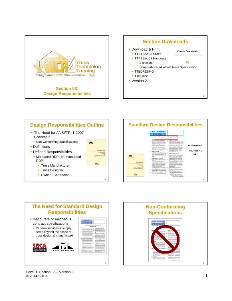
1 Level 1: Section 03 – Version 3 © 2014 SBCA 1 Section 03: Design Responsibilities 2 Section Downloads Download & Print TTT I Sec 03 Slides TTT I Sec 03 Handouts 2 articles Shop Fabricated Wood Truss Specification TTBDRESP-D TTBPlace Version 2.1 3 Design Responsibilities Outline The Need for ANSI/TPI 1-2007 Chapter 2 Non-Conforming Specifications Definitions Defined Responsibilities Mandated RDP / No mandated RDP Truss Manufacturer Truss Designer Owner / Contractor 4 Standard Design Responsibilities TTBDRESP-D 5 The Need for Standard Design Responsibilities Inaccurate or erroneous contract specifications Perform services & supply items beyond the scope of truss design & manufacture 6 Non-Conforming Specifications
-
Upload
truongdiep -
Category
Documents
-
view
217 -
download
0
Transcript of Design Responsibilities Outline Standard Design ... Responsibilities Outline ... revised, approved &...
1Level 1: Section 03 – Version 3© 2014 SBCA
1
Section 03: Design Responsibilities
2
Section Downloads
Download & Print TTT I Sec 03 Slides
TTT I Sec 03 Handouts
2 articles
Shop Fabricated Wood Truss Specification
TTBDRESP-D
TTBPlace
Version 2.1
3
Design Responsibilities Outline
The Need for ANSI/TPI 1-2007 Chapter 2 Non-Conforming Specifications
Definitions
Defined Responsibilities Mandated RDP / No mandated
RDP
Truss Manufacturer
Truss Designer
Owner / Contractor4
Standard Design Responsibilities
TTBDRESP-D
5
The Need for Standard Design Responsibilities
Inaccurate or erroneous contract specifications Perform services & supply
items beyond the scope of truss design & manufacture
6
Non-Conforming Specifications
2Level 1: Section 03 – Version 3© 2014 SBCA
7
“All other truss bracing required during the erection or in the completed structure including the bracing connections to trusses and bracing anchorage is the responsibility of the Truss Designer & should be clearly denoted on the Truss Design Drawings.”
“Truss Manufacturer is also responsible for supplying all bracing & connections.”
Non-Conforming Specifications
8
“The Truss Designer is solely responsible for the safety & stability of the roof system & its component parts during erection.”
“This includes the addition of whatever shoring, temporary bracing, guys or tie-downs, which might be necessary.”
Non-Conforming Specifications
9
“The Truss Designer needs to provide a letter of verification that trusses are installed & braced properly.”
“The Truss Designer must design all beams & headers.”
“The Truss Designer must provide sealed Placement Diagrams.”
Non-Conforming Specifications
10
Development
11
Development
12
Quiz 1
3Level 1: Section 03 – Version 3© 2014 SBCA
Definitions
ANSI/TPI 1-2007 Chapter 2
Definitions are not in the Standard Responsibilities TTB
Most were not covered in Section 2 – Terminology
See Shop Fabricated Wood Truss specification
13
Trusspec
Building
A structure used or intended for supporting or sheltering any use or occupancy.
14
Building Code
As it applies to the structural safety of a Building, any set of standards set forth and enforced by a Jurisdiction for the protection of public safety.
15 16
Building Designer
The Owner of the Building or the person that contracts with the Owner for the design of the Framing Structural System and/or who is responsible for the preparation of the Construction Documents. When mandated by the Legal Requirements, the Building Designer shall be a Registered Design Professional. On professionally designed projects
On projects where there is no professional designer
Building Official
A person charged with the administration and enforcement of a Building Code, or a person, who in accordance with the Legal Requirements may impose Legal Requirements relating to the Trusses and/or the Submittal Package.
17
Building Permit
An official certificate of permission issued by a Jurisdiction to an Owner to construct, enlarge, or alter a Building.
18
4Level 1: Section 03 – Version 3© 2014 SBCA
Construction Documents
Written, graphic and pictorial documents prepared or assembled for describing the design (including the Framing Structural System), location and physical characteristics of the elements of a Building necessary to obtain a Building Permit and construct a Building.
19
Contract
A legally recognized agreement between two parties. A Contract will likely exist between the
Truss Manufacturer and its customer, which may be the Contractor or Owner, which sets forth the responsibilities applicable to the Truss Manufacturer.
20
21
Contractor
An Owner of a Building, or the person who contracts with the Owner, who constructs the Building in accordance with the Construction Documents and the Truss Design Drawings and Truss Placement Plans if applicable. The term "Contractor" shall include those subcontractors who have a direct contract with the Contractor to perform all or a portion of the construction.
Cover/Truss Index Sheet
A sheet that is signed and sealed, where required by the Legal Requirements, by the Truss Design Engineer and depending on the Legal Requirements shall be permitted to contain the following information:
Replaces sealing each individual Truss Design Drawing (allowed by IBC)
22
Cover/Truss Index Sheet (1) identification of the Building, including Building name and address,
lot, block, subdivision and city or county;
(2) Identification of construction documents by drawing number(s) with revision date; (3) specified building code;
(4) computer program used;
(5) roof dead and live loads;
(6) floor dead and live loads;
(7) wind load criteria from a specifically defined code (for example, ASCE 7) and any other design loads (such as ponding, mechanical loads, etc.);
(8) name, address, and license number of Registered Design Professional for the building, if known;
(9) a listing of the individual identification numbers and dates of each Truss Design Drawing referenced by the Cover/Truss Index Sheet; and
(10) name, address, date of drawing and license number of Truss Design Engineer. 23
Deferred Submittal
Those portions of the design that are not completed at the time of the application for the Building Permit and that are to be submitted to the Building Official within a specified period in accordance with the Legal Requirements .
24
5Level 1: Section 03 – Version 3© 2014 SBCA
Diagonal Bracing
Structural member installed at an angle to a Truss chord or web member and intended to temporarily and/or permanently stabilize Truss Members and/or Trusses. For further information see BCSI.
25
Framing Structural System
The completed combination of Structural Elements, Trusses, connections and other systems, which serve to support the Building's self weight, the specified loads.
26
Jurisdiction
The Governmental unit that is responsible for adopting and enforcing the Building Code.
27
Lateral Restraint
Also known as Continuous Lateral Restraint or CLR. A structural member installed at right angles to a chord or web member of a Truss to reduce the laterally unsupported length of the Truss member.
28
29
Applicable provisions of all statutes, laws, rules, regulations, ordinances, codes, or orders of any governmental authority.
Legal Requirements
30
A person having a legal or equitable interest in the property upon which a Building is to be constructed, and:
(1) either prepares, or retains the Building Designer or Registered Design Professional to prepare, the Construction Documents; and
(2) either constructs, or retains the Contractor to construct the Building.
Owner
6Level 1: Section 03 – Version 3© 2014 SBCA
Permanent Building Stability Bracing
Lateral force resisting system for the Building that resists forces from gravity, wind, seismic and/or other loads.
31
Permanent Individual Truss Member Restraint
Restraint that is used to prevent local buckling of an individual Truss chord or web member due to the axial forces in the individual Truss member.
32
Person
An individual or organization that may exist in accordance with the Legal Requirements.
33
Registered Design Professional
Architect or engineer, who is licensed to practice their respective design profession as defined by the Legal Requirements of the Jurisdiction in which the Building is to be constructed.
34
Structural Element
A single structural member (other than a Truss) that is specified in the Construction Documents.
35
Temporary Installation Restraint/Bracing
Lateral Restraint and Diagonal Bracing installed during construction for the purposes of holding Trusses in their proper location, plumb and in plane, until Permanent Individual Truss Member Restraint, Diagonal Bracing and Permanent Building Stability Bracing are completely installed.
36
7Level 1: Section 03 – Version 3© 2014 SBCA
37
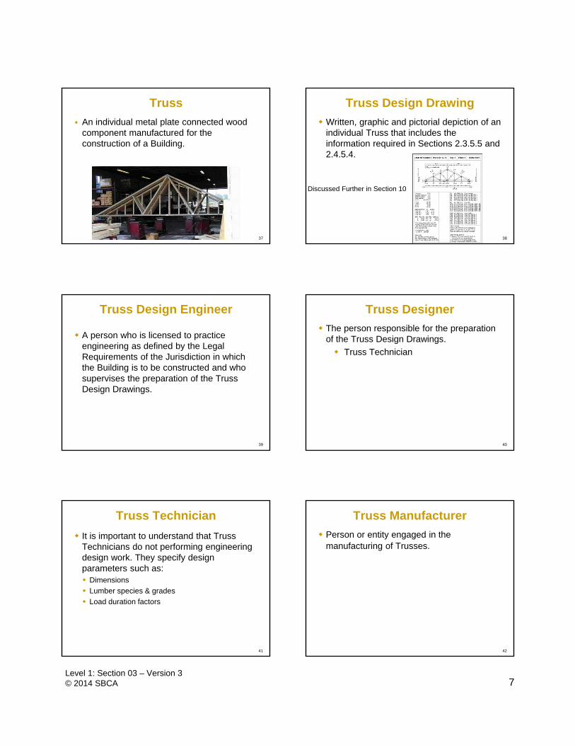
An individual metal plate connected wood component manufactured for the construction of a Building.
Truss Truss Design Drawing
Written, graphic and pictorial depiction of an individual Truss that includes the information required in Sections 2.3.5.5 and 2.4.5.4.
38
Discussed Further in Section 10
39
A person who is licensed to practice engineering as defined by the Legal Requirements of the Jurisdiction in which the Building is to be constructed and who supervises the preparation of the Truss Design Drawings.
Truss Design Engineer Truss Designer
The person responsible for the preparation of the Truss Design Drawings.
Truss Technician
40
41
It is important to understand that Truss Technicians do not performing engineering design work. They specify design parameters such as: Dimensions
Lumber species & grades
Load duration factors
Truss Technician
42
Truss Manufacturer
Person or entity engaged in the manufacturing of Trusses.
8Level 1: Section 03 – Version 3© 2014 SBCA
43
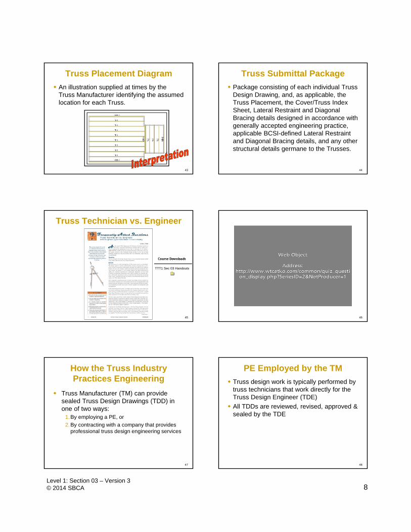
Truss Placement Diagram
An illustration supplied at times by the Truss Manufacturer identifying the assumed location for each Truss.
Truss Submittal Package
Package consisting of each individual Truss Design Drawing, and, as applicable, the Truss Placement, the Cover/Truss Index Sheet, Lateral Restraint and Diagonal Bracing details designed in accordance with generally accepted engineering practice, applicable BCSI-defined Lateral Restraint and Diagonal Bracing details, and any other structural details germane to the Trusses.
44
45
Truss Technician vs. Engineer
TTT1 Sec 03 Handouts
46
Quiz 2
How the Truss Industry Practices Engineering
Truss Manufacturer (TM) can provide sealed Truss Design Drawings (TDD) in one of two ways:
1.By employing a PE, or
2.By contracting with a company that provides professional truss design engineering services
47
PE Employed by the TM
Truss design work is typically performed by truss technicians that work directly for the Truss Design Engineer (TDE)
All TDDs are reviewed, revised, approved & sealed by the TDE
48
9Level 1: Section 03 – Version 3© 2014 SBCA
PE Employed via Contract
Typically the contract is with the truss plate & truss design software companies
Specific design parameters provided by the Building Designer are communicated from the TM to the contracted TDE.
TDE inputs these design parameters, analyzes & undertakes the truss design
TDE has complete control over the design settings.
49 50
Logical (Ideal) Design/Build Process
1) Owner hires a design team to undertake the architectural & structural design
2) Structural design team decides to use trusses & gets the TM involved during the project design phase
51
Logical (Ideal) Design/Build Process
3) Trusses are designed per the loading requirements provided by the Registered Design Professional (RDP) for the project
4) Completed TDDs are provided to the RDP who takes this information & designs the transfer of loads to the structure below
Permanent bracing design is also completed at this time
52
Logical (Ideal) Design/Build Process
5) Contractor takes the completed set of plans & implements them
6) Building Official performs an inspection to ensure that all involved in the project have not missed a detail that needed to be installed
53
Typical Process
1) $$$$$ is the main issue
2) Owner bypasses the RDP & just hires a General Contractor (GC)
3) GC gets bids from a variety of TMs of varying expertise & chooses the cheapest
54
Typical Process4) Plans & specifications for the project are
highly variable with respect to completeness & detail
5) Truss Manufacturer is asked to: “make them work structurally”,
define the loads (if not defined), &
make sure that the building as designed meets the expectations of everyone involved
10Level 1: Section 03 – Version 3© 2014 SBCA
Truss Design Drawing
The standard contract that the TM makes is for the individual trusses
May or may not require sealing
55 56
Truss Placement Diagram
TTBPLACE-D
57
Truss Placement Diagram
58
The Truss Designer’s signature certifies that the individual truss designs are based on the positioning shown, and that the dimensions and loads shown on the referenced drawings match that positioning. The Truss Designer’s seal on the attached Truss Design Drawings indicates acceptance of professional engineering responsibility solely for the individual Truss Design Drawings shown. The suitability and use of this component for any particular building is the responsibility of the Building Designer, per ANSI/TPI 1-2002 Chapter 2. No building design or inspection is implied by the seals on the Truss Design Drawings or Truss Placement Diagram. Verification that position, dimensions, and loads for each truss matches the construction design documents and/or intent is the responsibility of the Building Designer. The Truss Designer is responsible for the correct application of the specified loading provided to him by the Building Designer and for the truss to truss connections.
The Truss Designer is NOT responsible for:
The transfer of lateral load from the roof to the shear walls, connection of trusses to the bearing support, the design of the bearing supports, temporary and permanent building bracing required in the roof and/or floor system, transfer of vertical loads down to the foundation, the design of the foundation and soil, analysis of the roof and/or floor diaphragms of the building, connection of roof and/or floor diaphragm to the truss, specifying loading used in the design of the trusses.
The Building Designer shall ascertain that the loads utilized on the Truss Design Drawings meet or exceed the loading imposed by the building code.
Truss Placement Diagram Sample Disclaimer
Truss Placement Diagram
sbcindustry.com
Technical Info
Tech Notes
Continuous lateral bracing
Seals and Truss Placement Diagrams
Jobsite handling and installation
59
Mandated RDP
ANSI/TPI 1-2007 Chapter 2, Section 2.3 2.3.1 REQUIREMENTS OF THE OWNER
2.3.2 REQUIREMENTS OF THE REGISTERED DESIGN PROFESSIONAL
2.3.3 REQUIREMENTS FOR THE PERMANENT MEMBER RESTRAINT/ BRACING OF TRUSS SYSTEMS
2.3.4 REQUIREMENTS OF THE CONTRACTOR
2.3.5 REQUIREMENTS OF THE TRUSS DESIGN ENGINEER
2.3.6 REQUIREMENTS OF THE TRUSS MANUFACTURER
60
11Level 1: Section 03 – Version 3© 2014 SBCA
No mandated RDP
ANSI/TPI 1-2007 Chapter 2, Section 2.4 2.4.1 REQUIREMENTS OF THE OWNER
2.4.2 REQUIREMENTS OF THE BUILDING DESIGNER
2.4.3 REQUIREMENTS FOR THE PERMANENT MEMBER RESTRAINT/ BRACING OF TRUSS SYSTEMS
2.4.4 REQUIREMENTS OF THE CONTRACTOR
2.4.5 REQUIREMENTS OF THE TRUSS DESIGNER
2.4.6 REQUIREMENTS OF THE TRUSS MANUFACTURER
61 62
Defined Responsibilities
Requirements of the Owner
Requirements of the Contractor
Requirements of the RDP/Building Designer
Requirements of the Truss Design Engineer/ Truss Designer
Requirements of the Truss Manufacturer
Requirements for the Permanent Member Restraint/ Bracing of Truss Systems
63
Owner Responsibilities
Obtain the Building Permit
Communicate to the Contractor or Truss Manufacturer any required special inspections or structural observations
Engage with: RDP/Building Designer to prepare the
Construction Documents
Contractor to store, handle, & install trusses
Review & Coordinate the Submittal Packages
64
Long Span Trusses
Special on-site inspections of trusses with a clear span of 60' or greater Owner will contract with a RDP
To design the Temporary Installation Restraint/Bracing & the Permanent Individual Truss Member Restraint & Diagonal Bracing
To provide special inspections to assure that the temporary & permanent bracing are installed properly in the case of long-span trusses
65
Contractor Responsibilities Provide Construction Documents to the Truss
Manufacturer Provide Truss Submittal Package to
RDP/Building Designer for review/ approval Properly restore, handle, install, restrain, &
brace trusses Pre- & Post-Installation Check Needed truss repairs?
66
RDP/Building Designer Responsibilities
Prepare the Construction Documents With required information to accurately design the
trusses for the Building
Review the Truss Submittal Packages for compatibility with the Building design
12Level 1: Section 03 – Version 3© 2014 SBCA
67
Truss Design Engineer/ Truss Designer Responsibilities
Prepare Truss Design Drawings that conform to ANSI/TPI 1
Responsible only for the truss
Referred to as a Truss Design Engineer when seal is required
Prepare repair designs
NOT responsible for specifying design loads for trusses
68
Communicate design criteria to Truss Designer
Provide sealed Truss Design Drawings prepared by the Truss Design Engineer where required
Manufacture trusses in accordance with given plans
Manufacture trusses in accord with approved Truss Design Drawings using quality criteria per ANSI/TPI 1
Prepare Truss Placement Diagrams where required by the Contract
Submit Truss Placement Diagrams to Contractor for approval
Truss Manufacturer Responsibilities
69
Storage, Handling, Installing & Bracing
Truss Designers & Manufacturers are NOTresponsible.
Contractor IS responsible.
70
Permanent Bracing RDP/ Building Designer is responsible for
the trusses’ permanent bracing design If the truss members need to be braced
(restrained)- determining the approximate location is the responsibility of the Truss Design Engineer/ Truss Designer
71
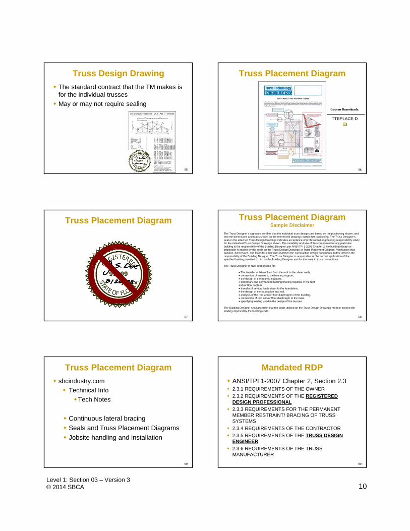
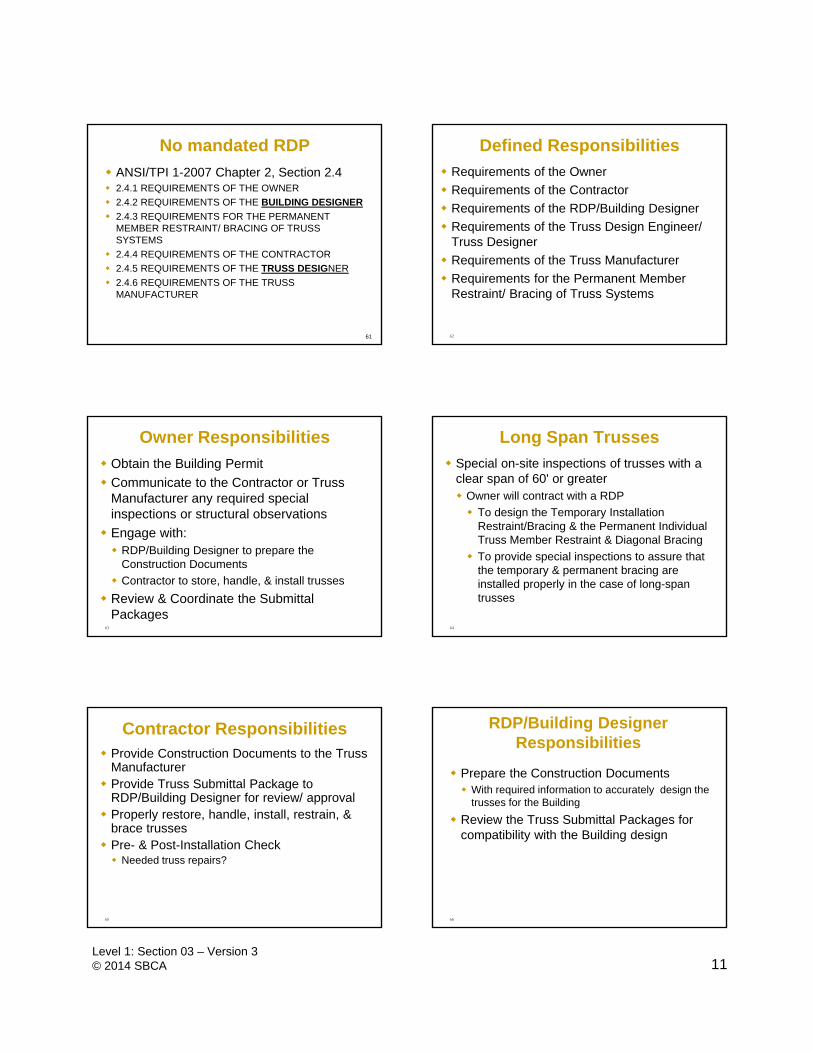
Permanent Individual Web Member Restraint
Compression Web Restraint
72
Web Buckling
13Level 1: Section 03 – Version 3© 2014 SBCA
73
Requirements for the Permanent Member Restraint/ Bracing of Truss Systems
TPI provides three methods for Permanent Individual Truss Member Restraint/Bracing Standard industry details per BCSI
Substitution with Reinforcement
Specific method specified by a RDP
In the absence of specific details, use the BCSI documents.
74
BCSI
Terminology changed to reflect BCSI language CLR vs. CLB
BCSI listed as a method to provide permanent individual truss member restraint/bracing
75
Standard Design Responsibilities
Chapter 2
76
Quiz 3
77
Feedback