Design Report - INTERNATIONAL SUBMARINE RACES
21
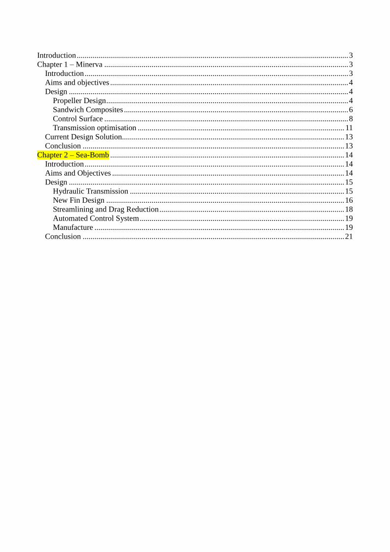
2/5/2011 Bath University Racing Submarine Team |BURST MINERVA & SEABOMB DESIGN REPORT
Transcript of Design Report - INTERNATIONAL SUBMARINE RACES
2/5/2011
Bath University Racing Submarine Team |BURST
MINERVA &
SEABOMB DESIGN REPORT
Introduction .......................................................................................................................................... 3
Chapter 1 – Minerva ............................................................................................................................ 3
Introduction ...................................................................................................................................... 3
Aims and objectives ......................................................................................................................... 4
Design .............................................................................................................................................. 4
Propeller Design ........................................................................................................................... 4
Sandwich Composites .................................................................................................................. 6
Control Surface ............................................................................................................................ 8
Transmission optimisation ......................................................................................................... 11
Current Design Solution................................................................................................................. 13
Conclusion ..................................................................................................................................... 13
Chapter 2 – Sea-Bomb ....................................................................................................................... 14
Introduction .................................................................................................................................... 14
Aims and Objectives ...................................................................................................................... 14
Design ............................................................................................................................................ 15
Hydraulic Transmission ............................................................................................................. 15
New Fin Design ......................................................................................................................... 16
Streamlining and Drag Reduction .............................................................................................. 18
Automated Control System ........................................................................................................ 19
Manufacture ............................................................................................................................... 19
Conclusion ..................................................................................................................................... 21
Introduction
BURST first entered the ISR human powered submarine competition in 2007 with SeaBomb, which
is a one-man, non-propeller design, and finished 2nd place in its category. The following event, Sulis
was entered. This submersible had the same hull design as the SeaBomb but a hybrid thrust system
was used; leading to a new hybrid category being created and bio-mimetic propulsion into the
design. This year, BURST has two submersibles competing, the improved SeaBomb and a new
design, Minerva, which is our first contribution to the Propeller category.
This report is compiled of two chapters each addressing the separate designs for each submarine.
BURST is made up of 12 final year students studying for a master’s in varying branches of
engineering. The design responsibilities for each submarine have been spread amongst the team
which have then been adapted to be the focus of their final year project, a 15,000 word thesis,
contributing to 20% of their overall degree mark. The conclusions and summaries drawn from each
individual project have been documented in this report, and concluded how the findings have
been used to create the new Minerva submarine.
Chapter 1 – Minerva
Introduction
The Minerva submarine was conceptualised last year by the penultimate year engineering team,
most of whom have carried on through to this year’s BURST team. The Minerva team have
therefore used the concept design from last year as a starting point and then used their research
projects to design and test the systems to turn the Minerva from a concept to a fully functional
human powered submarine.
The team have been split into two sub-teams, each focussing on either the SeaBomb or the
Minerva; the team that will be working on Minerva is:
Radomir Rashkov – Sandwich composites
Nicola Keen – Automated Yaw control
Isabel Hoskin – Control Surfaces
Thomas Stevenson – Propeller Design
Evangelos Christidis – Propeller Design
Matthew Parramore – Pilot to propeller interfaces
Aims and objectives
Minerva is BURST’s first venture into using a solely propeller thrust system, our overall aim is to
produce a human powered submarine that can reach a minimum of 6.4 knots over 100m sprint.
For this to be achieved, research was carried out in propeller design, sub assembly interfaces,
control, the pilot environment and hull manufacture. Research on safety aspects had already been
completed for the SeaBomb and Sulis, this information was adapted for use on Minerva.
Design
Propeller Design
The aim of the propeller research was to optimise the design of the propeller that will accelerate
the submarine to the greatest possible speed in a 70m run up. It was decided to adopt a two
bladed propeller with a large diameter of 0.7m to maximise efficiency.
One key aspect of the project was designing the propeller to operate most efficiently in the hull’s
wake. This investigation was broken down in 2 stages. First, a full scale prototype submarine was
used in open water testing to determine the drag coefficient, as shown in Figure 2, allowing an
initial maximum speed estimate of 5.4knots to be calculated, from which the propeller was
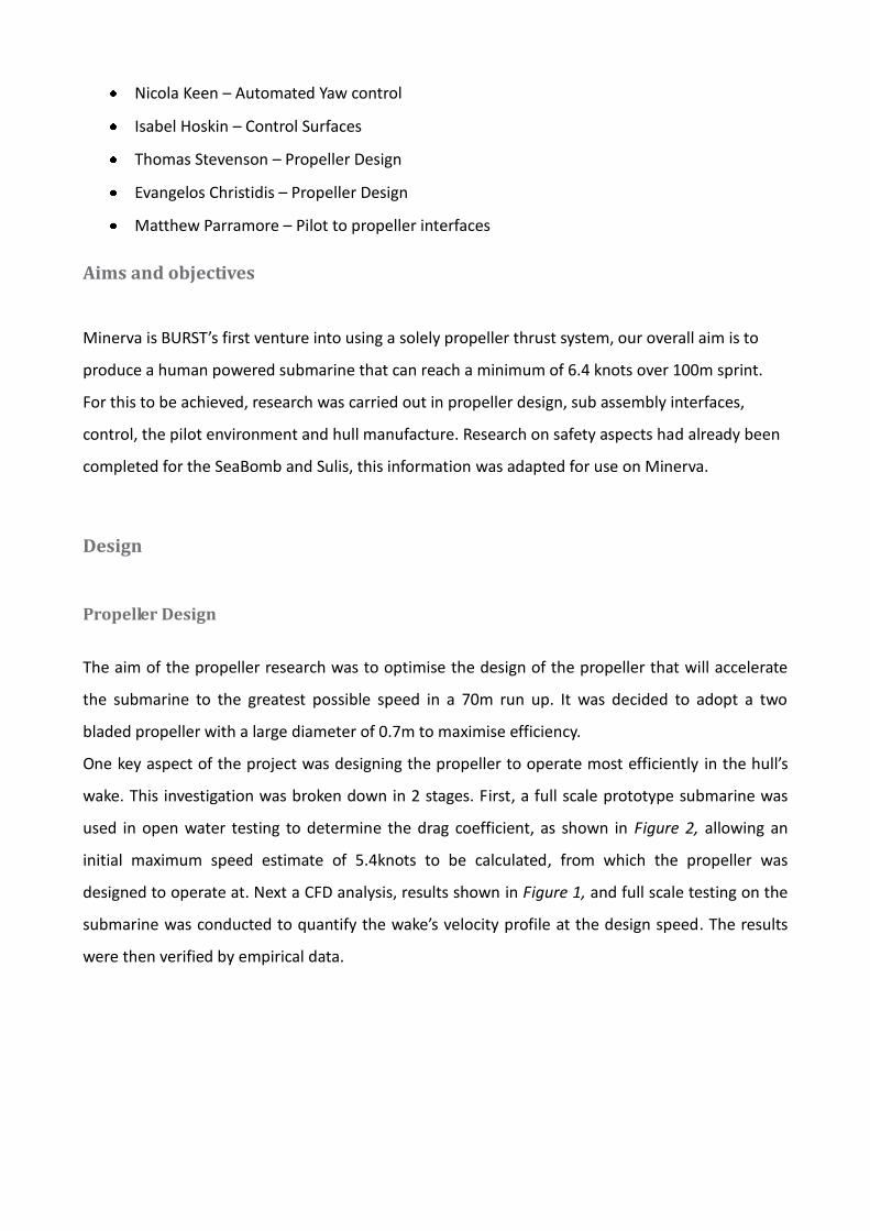
designed to operate at. Next a CFD analysis, results shown in Figure 1, and full scale testing on the
submarine was conducted to quantify the wake’s velocity profile at the design speed. The results
were then verified by empirical data.
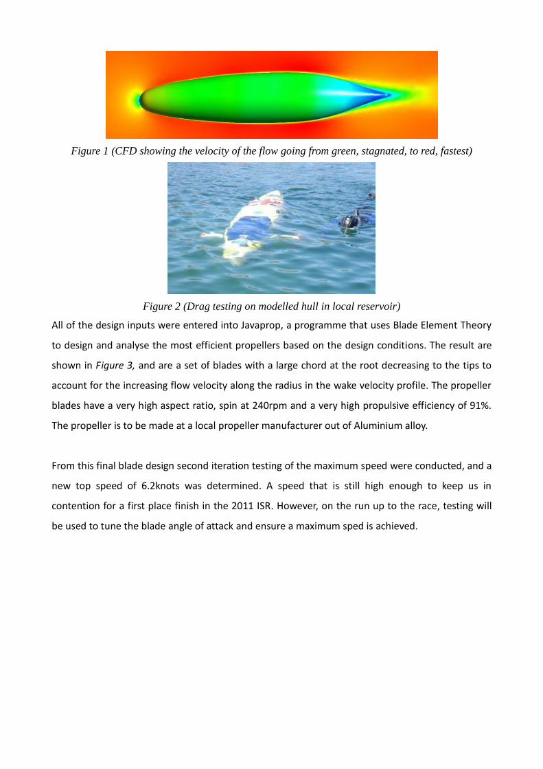
Figure 1 (CFD showing the velocity of the flow going from green, stagnated, to red, fastest)
Figure 2 (Drag testing on modelled hull in local reservoir)
All of the design inputs were entered into Javaprop, a programme that uses Blade Element Theory
to design and analyse the most efficient propellers based on the design conditions. The result are
shown in Figure 3, and are a set of blades with a large chord at the root decreasing to the tips to
account for the increasing flow velocity along the radius in the wake velocity profile. The propeller
blades have a very high aspect ratio, spin at 240rpm and a very high propulsive efficiency of 91%.
The propeller is to be made at a local propeller manufacturer out of Aluminium alloy.
From this final blade design second iteration testing of the maximum speed were conducted, and a
new top speed of 6.2knots was determined. A speed that is still high enough to keep us in
contention for a first place finish in the 2011 ISR. However, on the run up to the race, testing will
be used to tune the blade angle of attack and ensure a maximum sped is achieved.
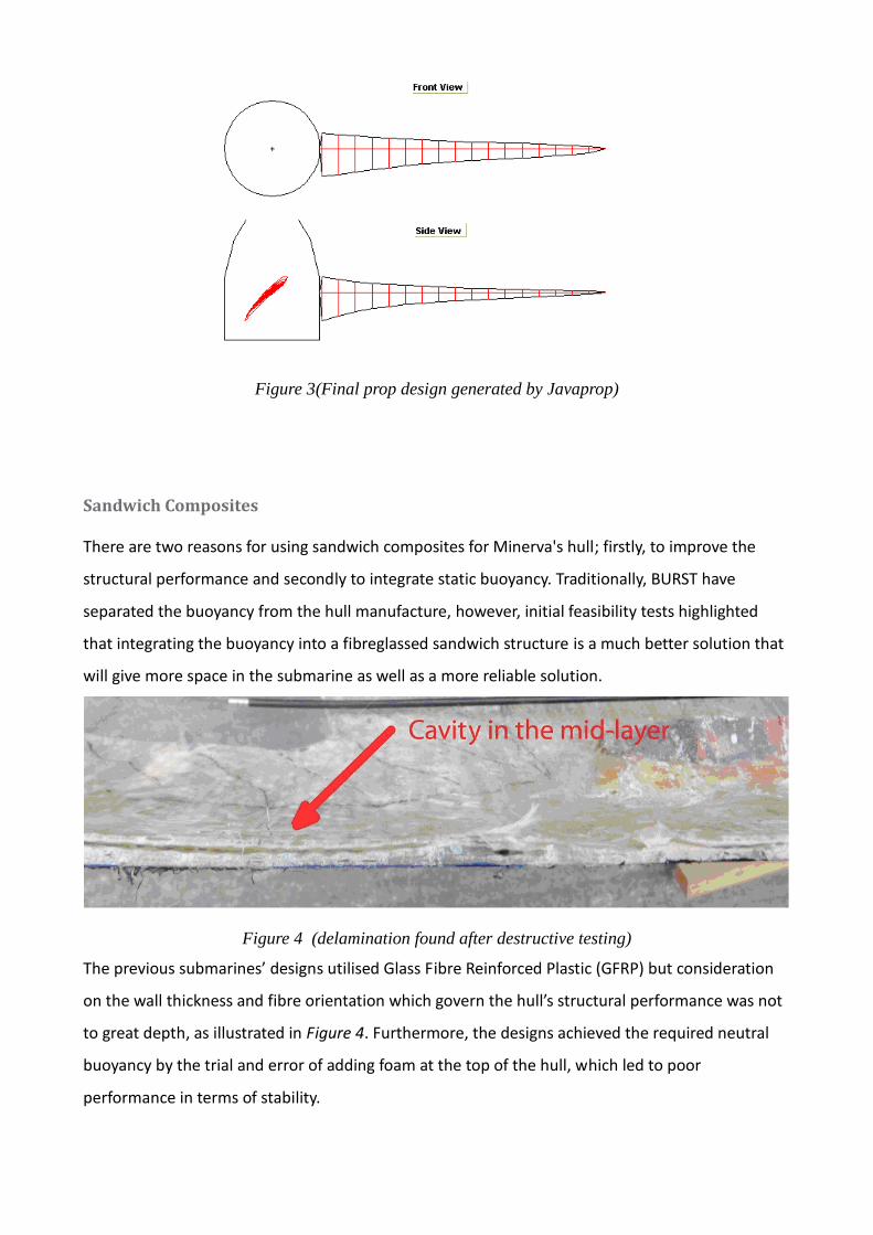
Figure 3(Final prop design generated by Javaprop)
Sandwich Composites
There are two reasons for using sandwich composites for Minerva's hull; firstly, to improve the
structural performance and secondly to integrate static buoyancy. Traditionally, BURST have
separated the buoyancy from the hull manufacture, however, initial feasibility tests highlighted
that integrating the buoyancy into a fibreglassed sandwich structure is a much better solution that
will give more space in the submarine as well as a more reliable solution.
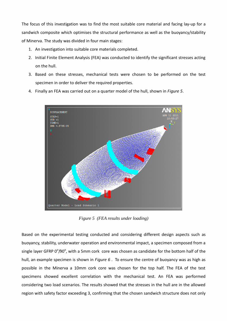
Figure 4 (delamination found after destructive testing)
The previous submarines’ designs utilised Glass Fibre Reinforced Plastic (GFRP) but consideration
on the wall thickness and fibre orientation which govern the hull’s structural performance was not
to great depth, as illustrated in Figure 4. Furthermore, the designs achieved the required neutral
buoyancy by the trial and error of adding foam at the top of the hull, which led to poor
performance in terms of stability.
The focus of this investigation was to find the most suitable core material and facing lay-up for a
sandwich composite which optimises the structural performance as well as the buoyancy/stability
of Minerva. The study was divided in four main stages:
1. An investigation into suitable core materials completed.
2. Initial Finite Element Analysis (FEA) was conducted to identify the significant stresses acting
on the hull.
3. Based on these stresses, mechanical tests were chosen to be performed on the test
specimen in order to deliver the required properties.
4. Finally an FEA was carried out on a quarter model of the hull, shown in Figure 5.
Figure 5 (FEA results under loading)
Based on the experimental testing conducted and considering different design aspects such as
buoyancy, stability, underwater operation and environmental impact, a specimen composed from a
single layer GFRP 0o/90o, with a 5mm cork core was chosen as candidate for the bottom half of the
hull, an example specimen is shown in Figure 6 . To ensure the centre of buoyancy was as high as
possible in the Minerva a 10mm cork core was chosen for the top half. The FEA of the test
specimens showed excellent correlation with the mechanical test. An FEA was performed
considering two load scenarios. The results showed that the stresses in the hull are in the allowed
region with safety factor exceeding 3, confirming that the chosen sandwich structure does not only
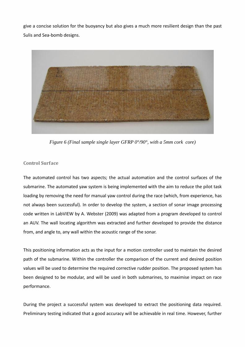
give a concise solution for the buoyancy but also gives a much more resilient design than the past
Sulis and Sea-bomb designs.
Figure 6 (Final sample single layer GFRP 0°/90°, with a 5mm cork core)
Control Surface
The automated control has two aspects; the actual automation and the control surfaces of the
submarine. The automated yaw system is being implemented with the aim to reduce the pilot task
loading by removing the need for manual yaw control during the race (which, from experience, has
not always been successful). In order to develop the system, a section of sonar image processing
code written in LabVIEW by A. Webster (2009) was adapted from a program developed to control
an AUV. The wall locating algorithm was extracted and further developed to provide the distance
from, and angle to, any wall within the acoustic range of the sonar.
This positioning information acts as the input for a motion controller used to maintain the desired
path of the submarine. Within the controller the comparison of the current and desired position
values will be used to determine the required corrective rudder position. The proposed system has
been designed to be modular, and will be used in both submarines, to maximise impact on race
performance.
During the project a successful system was developed to extract the positioning data required.
Preliminary testing indicated that a good accuracy will be achievable in real time. However, further
work is required before the final race, to allow for full implementation, this includes tuning of the
motion controller and integration with the control hardware.
This sonar system has been combined with new control surfaces, which have been designed to add
minimal drag, while providing a balance between adequate stability and manoeuvrability.
The layout of the control surfaces is to stay the same as the Sulis submarine, with fore and aft dive
planes, and a single vertical rudder. The lower rudder of previous BURST submarines has been
removed to allow the boat to pull up if grounded on the bottom of the race tank.
Analysis of several airfoil profiles was undertaken; the NACA-00 symmetrical series was used, and a
thickness-to-chord ratio of 12% chosen. This profile had a good combination of high lift-to-drag
ratio and high stall angle, allowing the size to be minimised while retaining sufficient lifting forces.
An aspect ratio of 2.5 was then chosen as being high enough to reduce induced drag while still
being structurally strong and not so high as to induce large rolling moments on the boat. The
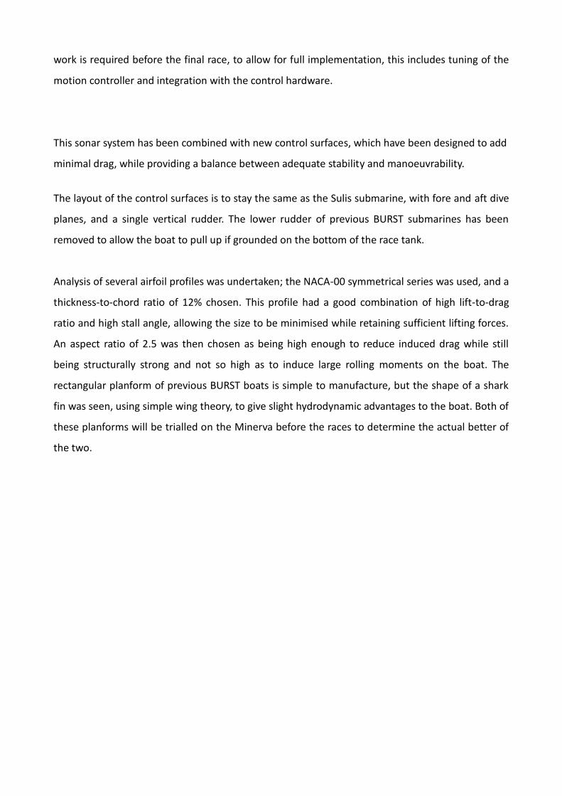
rectangular planform of previous BURST boats is simple to manufacture, but the shape of a shark
fin was seen, using simple wing theory, to give slight hydrodynamic advantages to the boat. Both of
these planforms will be trialled on the Minerva before the races to determine the actual better of
the two.
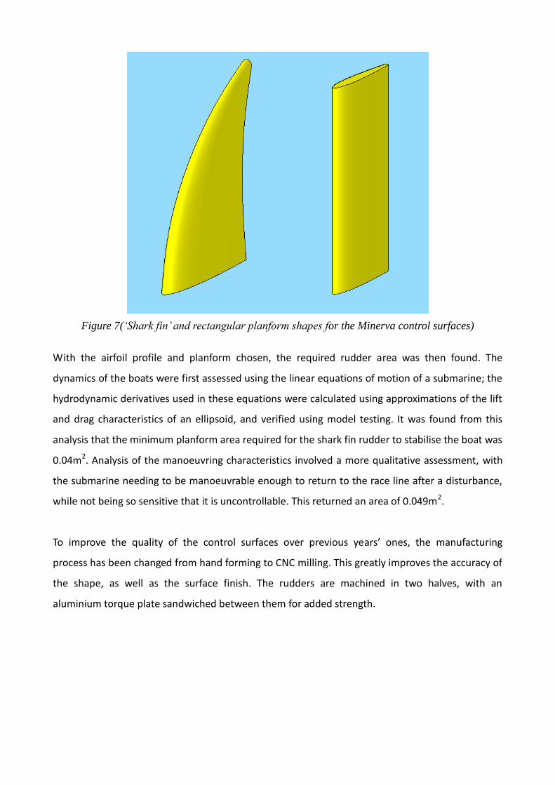
Figure 7(‘Shark fin’ and rectangular planform shapes for the Minerva control surfaces)
With the airfoil profile and planform chosen, the required rudder area was then found. The
dynamics of the boats were first assessed using the linear equations of motion of a submarine; the
hydrodynamic derivatives used in these equations were calculated using approximations of the lift
and drag characteristics of an ellipsoid, and verified using model testing. It was found from this
analysis that the minimum planform area required for the shark fin rudder to stabilise the boat was
0.04m2. Analysis of the manoeuvring characteristics involved a more qualitative assessment, with
the submarine needing to be manoeuvrable enough to return to the race line after a disturbance,
while not being so sensitive that it is uncontrollable. This returned an area of 0.049m2.
To improve the quality of the control surfaces over previous years’ ones, the manufacturing
process has been changed from hand forming to CNC milling. This greatly improves the accuracy of
the shape, as well as the surface finish. The rudders are machined in two halves, with an
aluminium torque plate sandwiched between them for added strength.
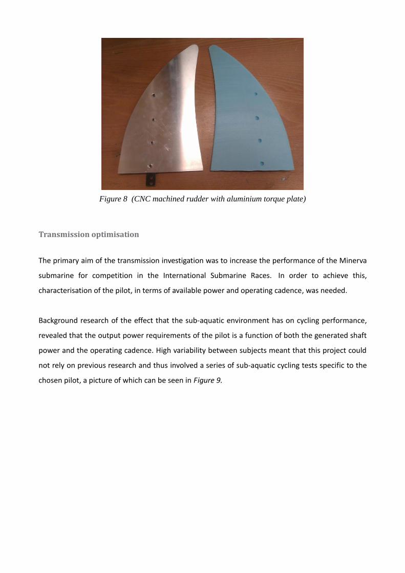
Figure 8 (CNC machined rudder with aluminium torque plate)
Transmission optimisation
The primary aim of the transmission investigation was to increase the performance of the Minerva
submarine for competition in the International Submarine Races. In order to achieve this,
characterisation of the pilot, in terms of available power and operating cadence, was needed.
Background research of the effect that the sub-aquatic environment has on cycling performance,
revealed that the output power requirements of the pilot is a function of both the generated shaft
power and the operating cadence. High variability between subjects meant that this project could
not rely on previous research and thus involved a series of sub-aquatic cycling tests specific to the
chosen pilot, a picture of which can be seen in Figure 9.
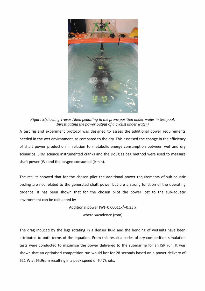
Figure 9(showing Trevor Allen pedalling in the prone position under-water in test pool.
Investigating the power output of a cyclist under water)
A test rig and experiment protocol was designed to assess the additional power requirements
needed in the wet environment, as compared to the dry. This assessed the change in the efficiency
of shaft power production in relation to metabolic energy consumption between wet and dry
scenarios. SRM science instrumented cranks and the Douglas bag method were used to measure
shaft power (W) and the oxygen consumed (l/min).
The results showed that for the chosen pilot the additional power requirements of sub-aquatic
cycling are not related to the generated shaft power but are a strong function of the operating
cadence. It has been shown that for the chosen pilot the power lost to the sub-aquatic
environment can be calculated by
Additional power (W)=0.00011x3+0.35 x
where x=cadence (rpm)
The drag induced by the legs rotating in a denser fluid and the bending of wetsuits have been
attributed to both terms of the equation. From this result a series of dry competition simulation
tests were conducted to maximise the power delivered to the submarine for an ISR run. It was
shown that an optimised competition run would last for 28 seconds based on a power delivery of
621 W at 65.9rpm resulting in a peak speed of 6.47knots.
Current Design Solution
The Minerva design has various aspects that have not been covered in as much depth as the
researched topics. The responsibilities for these were distributed amongst the team and addressed
below, along with how the separate design conclusions fit with each other.
The hull features 2 maintenance hatches, 1 safety hatch, fixed ribs and a panoramic Perspex
window, to allow for visibility; the control surfaces and nozzle will also be manufactured using
GFRPs. The pilot is in prone position with their head at the front of the submarine, as per the
results from the transmission test by Trevor Allen (2011). Sonar Automated controls are at the bow,
in front of the pilot, to allow for the controls to be visible to the pilot. As the controls are
automated, the pilot only needs to provide the power and to hold on to the dead-man switch,
which will release the emergency buoy if needed. The air tank sits behind the pilot in the centre of
the submarine. The required safety strobe light is to be placed to the rear of the submersible and
standard components and fixings will be used throughout the submersible. The dry mass of the
Minerva is predicted to be 126kg and has an estimated build cost of £3500.
The manufacture of the submarine will be done in-house by this year’s BURST team, as has been
done by previous BURST teams. The details of which are addressed in more detail in the following
chapter.
Conclusion
Minerva is a new design for BURST and we aim to reach its full potential in its first year. The key to
this success we believe is simplicity in design and manufacture to allow for the maximum amount
of testing time. Therefore more focus has been given to the manufacturing techniques of the
submarine from the beginning of its build and more consideration has been given to the pilot
environment so that he/she can reach their optimum performance. This year’s BURST team, as
usual, are manufacturing as much of Minerva in-house, which keeps the costs down, despite this,
with an estimated cost of £3500, Minerva will be our most expensive build yet, due to the new
features of this new build submarine. Previous BURST teams have relied on small donations from
local companies; this year we are aiming to raise the desired £3500 through sponsorship and
fundraising activities. We are aiming for greater pool of resources this year to allow for the building
of two submarines to a high quality of manufacture and componentry.
Chapter 2 – Sea-Bomb Introduction
The 2007 SeaBomb featured a reclined driver position and utilised a stepper motion rather than
the more common cycling, it used bike cable controlled dive planes and rudder and its propulsion
was provided by a pair of synchronised heaving foils with chord-wise flexibility. This package
achieved a top speed of 2.01knots. However due to the size of this year’s BURST it was decided
that we should adapt and improve Sea-Bomb with the key changes being using hydraulic control
and changing the ergonomics of the pilot environment, as addressed in the aims and objectives.
The SeaBomb team consists of:
Nathan Sell – Propulsion
Chris Britton – Transmission
Jeni Spillane – Integration of eco-composites
Will Almond – Drag reduction
Charles Wilson – Automated control
Trevor Allen – Pilot environment
Aims and Objectives
We at BURST feel that the SeaBomb never reached its full potential, thus we are giving it a new
lease of life. There are four key areas in which we are rebuilding and redesigning in the Sea-Bomb:
1. A new hydraulic transmission system
2. A new fin design
3. Streamlining and drag reduction
4. An automated control system
To be able to implement all these changes we are also aiming to raise £1000 of sponsorship money.
Previous BURST submarines have been funded by small donations from various different sources;
this has resulted in things being done on a shoe string budget (SeaBomb originally cost only £500
to make). We are hoping for more resource this year to enable the building of two submarines and
help improve the quality of manufacture and componentry.
Design
Hydraulic Transmission
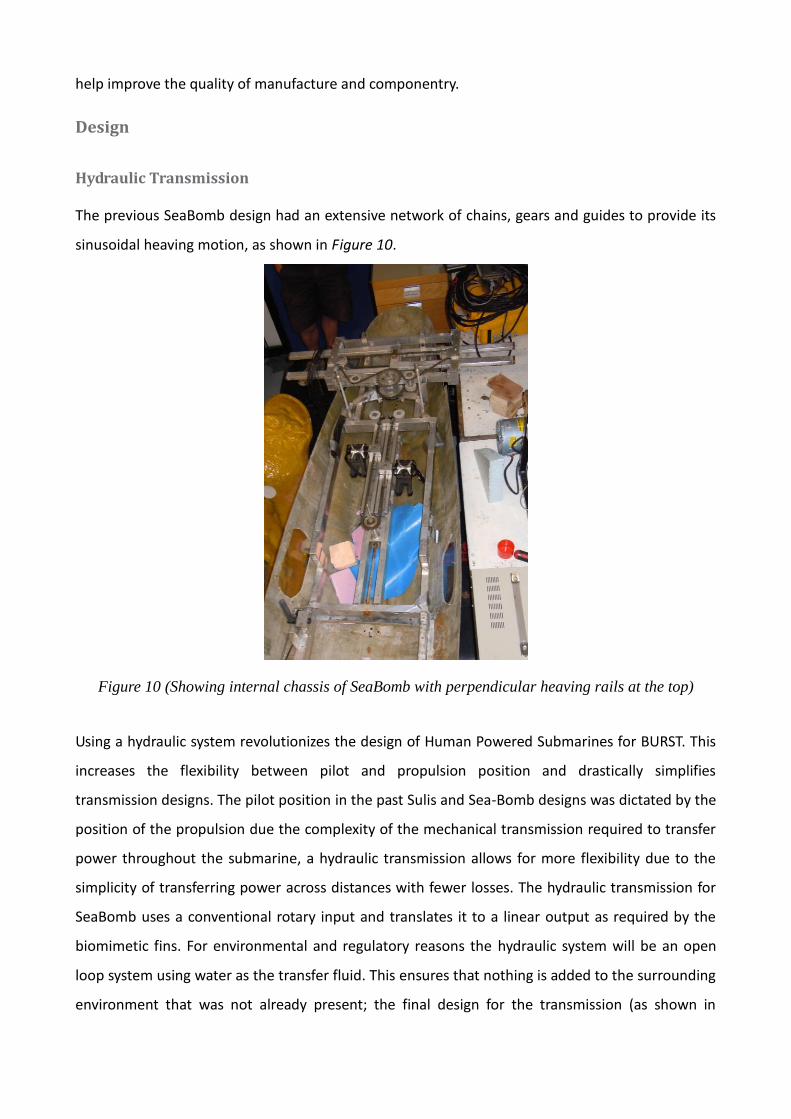
The previous SeaBomb design had an extensive network of chains, gears and guides to provide its
sinusoidal heaving motion, as shown in Figure 10.
Figure 10 (Showing internal chassis of SeaBomb with perpendicular heaving rails at the top)
Using a hydraulic system revolutionizes the design of Human Powered Submarines for BURST. This
increases the flexibility between pilot and propulsion position and drastically simplifies
transmission designs. The pilot position in the past Sulis and Sea-Bomb designs was dictated by the
position of the propulsion due the complexity of the mechanical transmission required to transfer
power throughout the submarine, a hydraulic transmission allows for more flexibility due to the
simplicity of transferring power across distances with fewer losses. The hydraulic transmission for
SeaBomb uses a conventional rotary input and translates it to a linear output as required by the
biomimetic fins. For environmental and regulatory reasons the hydraulic system will be an open
loop system using water as the transfer fluid. This ensures that nothing is added to the surrounding
environment that was not already present; the final design for the transmission (as shown in
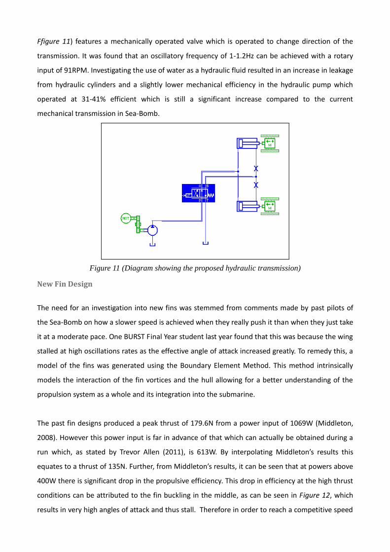
Ffigure 11) features a mechanically operated valve which is operated to change direction of the
transmission. It was found that an oscillatory frequency of 1-1.2Hz can be achieved with a rotary
input of 91RPM. Investigating the use of water as a hydraulic fluid resulted in an increase in leakage
from hydraulic cylinders and a slightly lower mechanical efficiency in the hydraulic pump which
operated at 31-41% efficient which is still a significant increase compared to the current
mechanical transmission in Sea-Bomb.
Figure 11 (Diagram showing the proposed hydraulic transmission)
New Fin Design
The need for an investigation into new fins was stemmed from comments made by past pilots of
the Sea-Bomb on how a slower speed is achieved when they really push it than when they just take
it at a moderate pace. One BURST Final Year student last year found that this was because the wing
stalled at high oscillations rates as the effective angle of attack increased greatly. To remedy this, a
model of the fins was generated using the Boundary Element Method. This method intrinsically
models the interaction of the fin vortices and the hull allowing for a better understanding of the
propulsion system as a whole and its integration into the submarine.
The past fin designs produced a peak thrust of 179.6N from a power input of 1069W (Middleton,
2008). However this power input is far in advance of that which can actually be obtained during a
run which, as stated by Trevor Allen (2011), is 613W. By interpolating Middleton’s results this
equates to a thrust of 135N. Further, from Middleton’s results, it can be seen that at powers above
400W there is significant drop in the propulsive efficiency. This drop in efficiency at the high thrust
conditions can be attributed to the fin buckling in the middle, as can be seen in Figure 12, which
results in very high angles of attack and thus stall. Therefore in order to reach a competitive speed
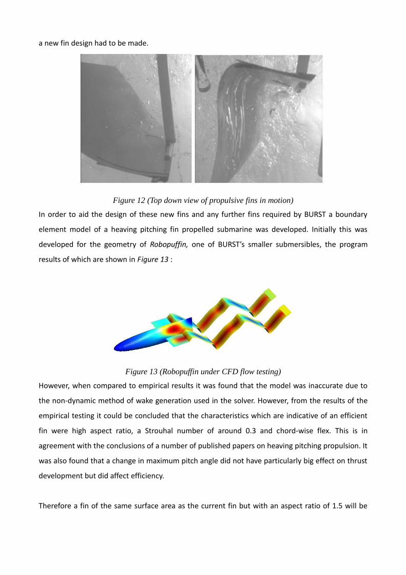
a new fin design had to be made.
Figure 12 (Top down view of propulsive fins in motion)
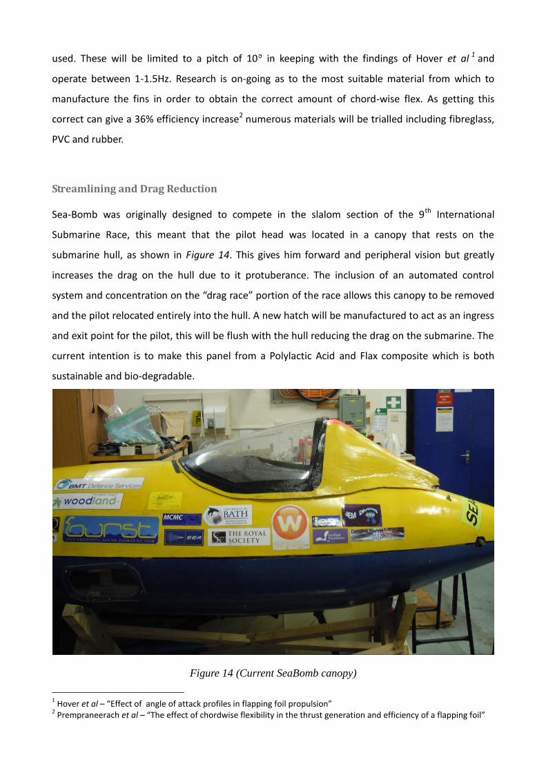
In order to aid the design of these new fins and any further fins required by BURST a boundary
element model of a heaving pitching fin propelled submarine was developed. Initially this was
developed for the geometry of Robopuffin, one of BURST’s smaller submersibles, the program
results of which are shown in Figure 13 :
Figure 13 (Robopuffin under CFD flow testing)
However, when compared to empirical results it was found that the model was inaccurate due to
the non-dynamic method of wake generation used in the solver. However, from the results of the
empirical testing it could be concluded that the characteristics which are indicative of an efficient
fin were high aspect ratio, a Strouhal number of around 0.3 and chord-wise flex. This is in
agreement with the conclusions of a number of published papers on heaving pitching propulsion. It
was also found that a change in maximum pitch angle did not have particularly big effect on thrust
development but did affect efficiency.
Therefore a fin of the same surface area as the current fin but with an aspect ratio of 1.5 will be
used. These will be limited to a pitch of 10 in keeping with the findings of Hover et al 1 and
operate between 1-1.5Hz. Research is on-going as to the most suitable material from which to
manufacture the fins in order to obtain the correct amount of chord-wise flex. As getting this
correct can give a 36% efficiency increase2 numerous materials will be trialled including fibreglass,
PVC and rubber.
Streamlining and Drag Reduction
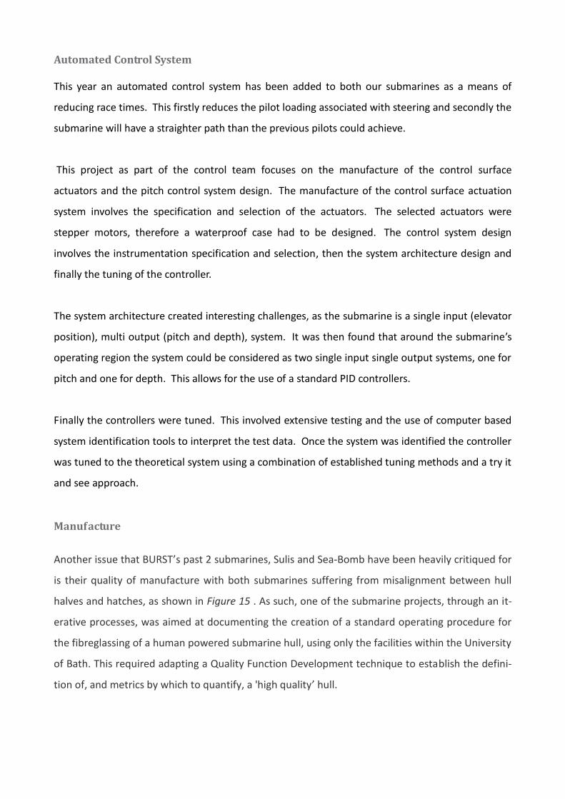
Sea-Bomb was originally designed to compete in the slalom section of the 9th International
Submarine Race, this meant that the pilot head was located in a canopy that rests on the
submarine hull, as shown in Figure 14. This gives him forward and peripheral vision but greatly
increases the drag on the hull due to it protuberance. The inclusion of an automated control
system and concentration on the “drag race” portion of the race allows this canopy to be removed
and the pilot relocated entirely into the hull. A new hatch will be manufactured to act as an ingress
and exit point for the pilot, this will be flush with the hull reducing the drag on the submarine. The
current intention is to make this panel from a Polylactic Acid and Flax composite which is both
sustainable and bio-degradable.
Figure 14 (Current SeaBomb canopy)
1 Hover et al – “Effect of angle of attack profiles in flapping foil propulsion”
2 Prempraneerach et al – “The effect of chordwise flexibility in the thrust generation and efficiency of a flapping foil”
Automated Control System
This year an automated control system has been added to both our submarines as a means of
reducing race times. This firstly reduces the pilot loading associated with steering and secondly the
submarine will have a straighter path than the previous pilots could achieve.
This project as part of the control team focuses on the manufacture of the control surface
actuators and the pitch control system design. The manufacture of the control surface actuation
system involves the specification and selection of the actuators. The selected actuators were
stepper motors, therefore a waterproof case had to be designed. The control system design
involves the instrumentation specification and selection, then the system architecture design and
finally the tuning of the controller.
The system architecture created interesting challenges, as the submarine is a single input (elevator
position), multi output (pitch and depth), system. It was then found that around the submarine’s
operating region the system could be considered as two single input single output systems, one for
pitch and one for depth. This allows for the use of a standard PID controllers.
Finally the controllers were tuned. This involved extensive testing and the use of computer based
system identification tools to interpret the test data. Once the system was identified the controller
was tuned to the theoretical system using a combination of established tuning methods and a try it
and see approach.
Manufacture
Another issue that BURST’s past 2 submarines, Sulis and Sea-Bomb have been heavily critiqued for
is their quality of manufacture with both submarines suffering from misalignment between hull
halves and hatches, as shown in Figure 15 . As such, one of the submarine projects, through an it-
erative processes, was aimed at documenting the creation of a standard operating procedure for
the fibreglassing of a human powered submarine hull, using only the facilities within the University
of Bath. This required adapting a Quality Function Development technique to establish the defini-
tion of, and metrics by which to quantify, a 'high quality’ hull.
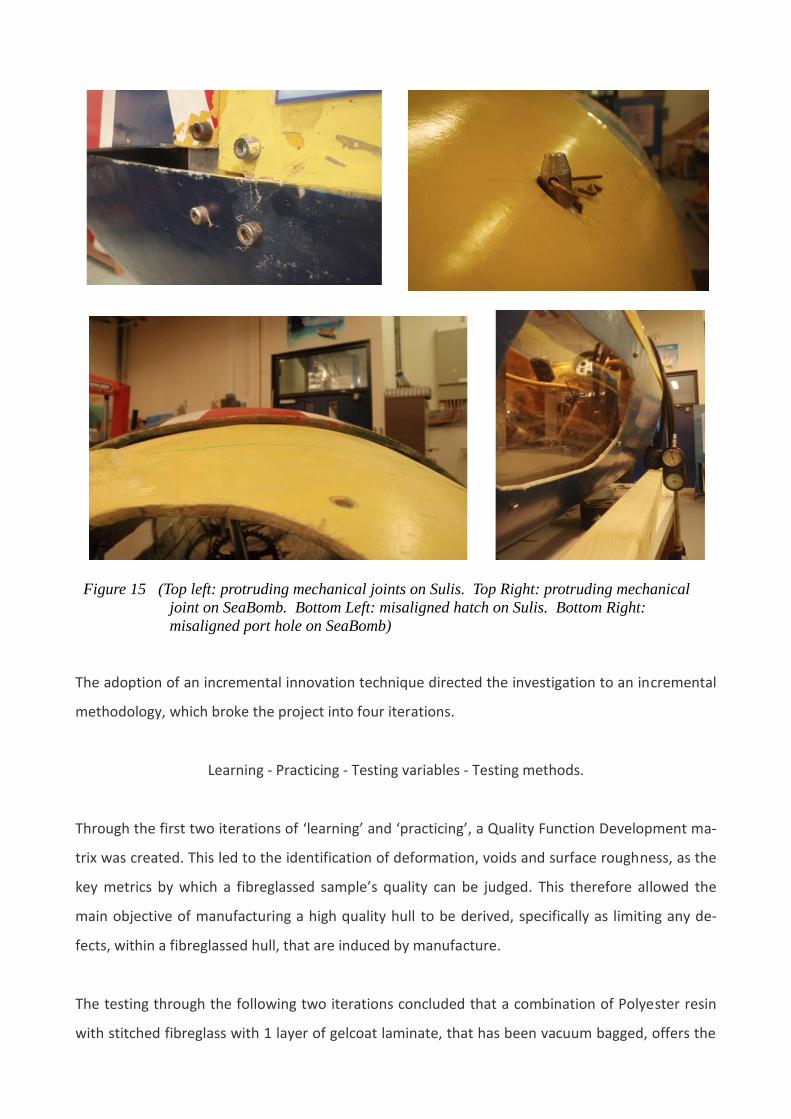
Figure 15 (Top left: protruding mechanical joints on Sulis. Top Right: protruding mechanical
joint on SeaBomb. Bottom Left: misaligned hatch on Sulis. Bottom Right:
misaligned port hole on SeaBomb)
The adoption of an incremental innovation technique directed the investigation to an incremental
methodology, which broke the project into four iterations.
Learning - Practicing - Testing variables - Testing methods.
Through the first two iterations of ‘learning’ and ‘practicing’, a Quality Function Development ma-
trix was created. This led to the identification of deformation, voids and surface roughness, as the
key metrics by which a fibreglassed sample’s quality can be judged. This therefore allowed the
main objective of manufacturing a high quality hull to be derived, specifically as limiting any de-
fects, within a fibreglassed hull, that are induced by manufacture.
The testing through the following two iterations concluded that a combination of Polyester resin
with stitched fibreglass with 1 layer of gelcoat laminate, that has been vacuum bagged, offers the
best attainable quality that BURST 2011 can accomplish in the production of both the new Miner-
va hull and the new hatches for the Sea-Bomb.
This project concluded by producing a standard operating procedure for the manufacture of a
human powered submarine hull, which aims to standardize the quality of manufacture for future
submarines.
Conclusion
The new Sea-Bomb design aims to show how BURST has developed over the past few years,
growing and expanding on past students’ knowledge to create a more successful submarine. The
decrease in weight and drag and increase in manufacture quality aims to give the new submarine a
much higher maximum velocity.