
Design & Prototyping of Hybrid Electric Vehicle Electronic Control Unit Dinçer Mehmet BAHAR Energy...
25
Design & Prototyping of Hybrid Design & Prototyping of Hybrid Electric Vehicle Electronic Control Electric Vehicle Electronic Control Unit Unit Dinçer Mehmet BAHAR Energy Institute 2008,Gebze
-
Upload
anaya-blish -
Category
Documents
-
view
227 -
download
5
Transcript of Design & Prototyping of Hybrid Electric Vehicle Electronic Control Unit Dinçer Mehmet BAHAR Energy...

Design & Prototyping of Hybrid Electric Design & Prototyping of Hybrid Electric Vehicle Electronic Control UnitVehicle Electronic Control Unit
Dinçer Mehmet BAHAREnergy Institute
2008,Gebze

TOPICS
•HEV & CONFIGURATIONS OF HEV•WHY DO WE NEED HECU?•HARDWARE STRUCTURE OF HECU•INPUTS & OUTPUTS OF HECU•CASING OF HECU•SOFTWARE DEVELOPMENT FOR HECU

Hybrid Electric Vehicles
• A hybrid electric vehicle (HEV) is the vehicle which has both internal combustion engine (ICE) and electric motor (EM).
ICE EM+

Hybrid Electric Vehicle Configurations
• Series HEV (SHEV):– SHEV is driven by only EM.
– SHEV contains ICE for generating electrical power to keep the batteries charged and propel the vehicle by the means of the electrical power through the generator when the State of Charge (SOC) of batteries is low.
EM+
GeneratorICE
Fuel Tank
Battery
Transmission
Dif.
ECU
HECU

Hybrid Electric Vehicle Configurations
• Parallel HEV (PHEV):– In PHEV, EM and ICE are connected together to the
transmission line where both of them or one by one can propel the vehicle.
– The batteries can be charged by ICE where EM acts as a generator or by regenerative braking.
MG
ICE
FuelTank
Battery
Transmission
Dif.
ECU
HECU
~
=
Hybrid Electric Vehicle Configurations
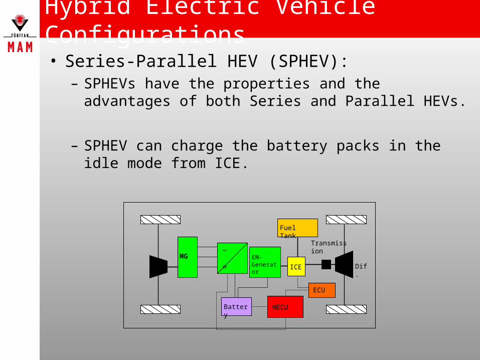
• Series-Parallel HEV (SPHEV):– SPHEVs have the properties and the advantages of
both Series and Parallel HEVs.
– SPHEV can charge the battery packs in the idle mode from ICE.
MG
ICE
Fuel Tank
Battery
Transmission
Dif.
ECU
~
=EM-Generator
HECU

Why Do We Need HECU?
• A hybrid vehicle has many subsystems:– ECU of the conventional
part of the vehicle
– ICE
– EM
– EM Driver
– Battery & BMS
Why Do We Need HECU?
All this subsystems needs a master controller to drive hybrid vehicle properly where HECU steps in with the ability of:
Understanding and giving meaning to drivers requests.
Understanding HEV’s situation with all subsystems conditions.
Response back and control the HEV according to the data collected in the previous steps.
Hardware Structure of HECU
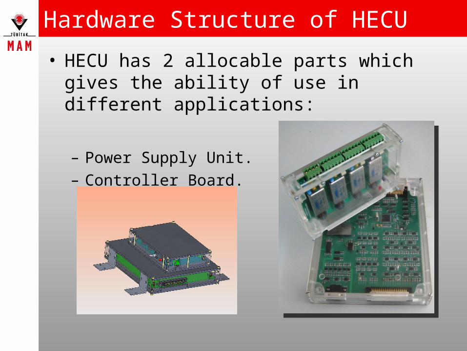
• HECU has 2 allocable parts which gives the ability of use in different applications:
– Power Supply Unit.– Controller Board.

Hardware Structure of HECU
• POWER SUPPLY UNIT:– From 12V vehicle battery, gives multiple power
solution for HECU and sensors that are needed to control the HEV.
– Has 4 high efficient DC-DC converters.– All converters are connected to the 12V vehicle
battery with LC filters to reduce ripples and suppress the noise on the power line.
Input voltage range : 9-18V Output voltage levels: 5V-12V-15V-24V

Hardware Structure of HECU
• Controller Board:– Digital Signal Controller:
• TI TMS320F2808 – 32-Bit High performance for complex algorithms with high efficiency in
math task.
– 100 MHZ Fixed-Point signal processor with internal flash.
– Peripherals of TMS320F2808:• 16 PWM (6 High resolution PWM)
• 6 32-Bit & 6 16-Bit Timers
• 12-Bit ADC, 2x8 channel Analog inputs with fast conversion rate.
• Up-to 35 individually programmable GPIO
• JTAG: advanced emulation features for analysis, real-time debugging and programming.
• 32 Mailbox, 2 Enhanced Controller Area Network(eCAN)
• Serial Communication Interface (SCI) to interface with computer
• Serial Peripheral Interface (SPI)

Hardware Structure of HECU
– HECU has 6 Layer PCB to reduce EMI/EMC related noises.
• Component layers: Top & Bottom layers are for localization of the active & passive circuit components.
• Ground Layer: Split Analog, Digital and Isolated grounds. Where all components and traces are placed only over their own ground regions.
ANALOG
GROUND
DIGITAL
GROUND
Common
Ground
ISOLATED
GROUND

Hardware Structure of HECU
• Signal Layer 1 & Signal Layer 2: Differential and single-ended signals are routed according to crosstalk and reflection consideration. Dif. Signals are routed as possible as each other where single-ended signal traces are routed at least 2 times the trace width apart from each other.
• No traces are routed parallel over
another trace on an other layer.
If they have to cross over, both
traces are routed with right angle
to minimize crosstalk.
• 90º bends are avoided and routed
with two 45º corners to minimize
any impedance change.

Hardware Structure of HECU
• Power layer: Split Multiple Power Layer. 24V, +12V, -12V, Analog 5V, 5V, 3.3V, Analog 3.3V, Analog 1.8V, 1.8V, 1.5V power planes.
• Active components are
connected to their related
power plane with 1µH
ferrite coil and 0.1µF
bypass capacitor for EMI
consideration.
• With split power planes none
of the components sourced over another component.

Inputs & Outputs of HECU
– I/O Structure:• HECU has many I & O to:
– understand the needs of the driver
– know condition of the subsystems of the HEV
– control the subsystems according to this information with the processing algorithm.
» Digital Inputs & Outputs
» Analog Inputs & Outputs
Inputs & Outputs of HECU
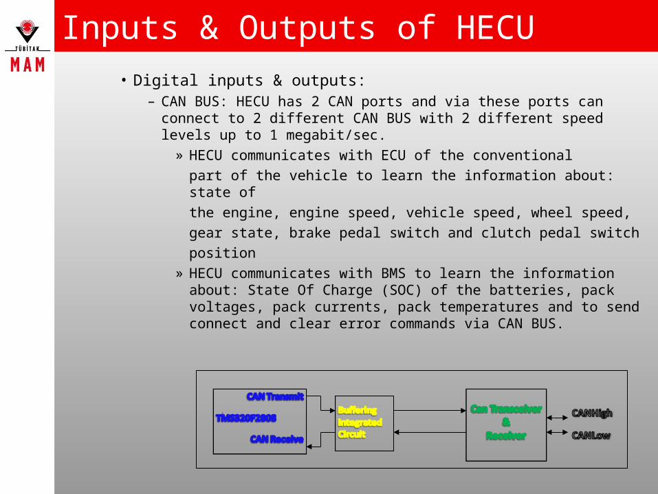
• Digital inputs & outputs:– CAN BUS: HECU has 2 CAN ports and via these ports can
connect to 2 different CAN BUS with 2 different speed levels up to 1 megabit/sec.
» HECU communicates with ECU of the conventional
part of the vehicle to learn the information about: state of
the engine, engine speed, vehicle speed, wheel speed,
gear state, brake pedal switch and clutch pedal switch
position
» HECU communicates with BMS to learn the information about: State Of Charge (SOC) of the batteries, pack voltages, pack currents, pack temperatures and to send connect and clear error commands via CAN BUS.

Inputs & Outputs of HECU– JTAG: HECU interfaces via CCS for programming and real-time
debugging and analysis.
– SERIAL BUS: Via SCI HECU can send software parameters to a computer for monitoring.
– PWM digital output for reference signal of ICE throttle pedal for ECU

Inputs & Outputs of HECU• Analog Inputs & Outputs:
– Analog Inputs: From throttle pedal position, brake pedal force, clutch pedal position and some more sensors HECU reads differential analog signals to understand drivers driving request. As all sensors have different range of output voltages, these signals must be scaled before they connect to DSP to be in the meaningful range of 0-3V.
» Voltage divider, differential and operational amplifiers are used.

Inputs & Outputs of HECU– Analog Outputs: HECU has 8 Analog outputs which are
generated by DAC with the drive of Serial Peripheral Interface (SPI) in the range of 0-5V.
» SPI sends 16 bit of data to 8 channels DAC. The first 4 bits are control bits that select the channel of the DAC and the other 12 bits are data bits.
» EM torque request, EM brake reference, EM direction and EM enable command signals are some example of analog outputs that HECU send to subsystems (which can be also be send as digital signal via CAN BUS to EM if EM is compatible)

Casing of HECU
– HECU has aluminum and plexiglas casings which are designed to fix the HECU into the HEV and reduce EMI/EMC.

Software Development of HECU
• HECU can be programmed either using conventional programming languages (Assembler, C, C++) or using Matlab/Simulink automatic code generation feature.
• HEV energy management algorithms are very complicated and mostly designed using Simulink
• Compatibility of HECU to Simulink allows rapid prototyping of algorithms which saves time during the R&D phase.

Software Development of HECU
• While rapid prototyping one should care about saturation, rounding and quantization effects because HECU has a Fixed-Point processor.
• Simulink helps developing Fixed-Point algorithms with Fixed-Point Toolbox where one can easily specify range and scaling factor for software variables.
• Developing algorithms for Fixed-point processors seems challenging at first but they reduces the cost of HECU’s processor price up 50%.

Conclusion
• HEVs are getting popular day by day because of the environmental point of view also the economical reasons of increasing cost of fossil fuels.
• Any kind of HEV needs a electronic control unit for subsystems added to make hybrid and also to communicate with the conventional part of the vehicle. HECU was designed to answer these needs with– low cost – high performance mathematical solutions for complex
algorithms.– Rapid prototyping features.

HECU was designed and developed in accordance with “Designing and Prototype Development of a Hybrid Electrical Vehicle Control Unit” project supported by FORD OTOSAN AŞ.

THANK YOU FOR YOUR ATTENTION.