DESIGN PROCESS AND MANUFACTURING OF AN UNMANNED BLENDED ...elib.dlr.de/98518/1/DLRK_2015_DESIGN...
16
DESIGN PROCESS AND MANUFACTURING OF AN UNMANNED BLENDED WING-BODY AIRCRAFT Benjamin Gramüller*, Felix Stroscher**, Jochen Schmidt*, Tanut Ungwattanapanit**, Thomas Löbel*, Michael Hanke* Abstract: The design process, the dimensioning, the proof and the manufacturing of a blended wing-body configuration aircraft with diamond shape is presented. The open collaboration project Sagitta is initiated by Airbus Defence and Space with the objective to investigate innovative aircraft configurations for future unmanned aerial systems (UAS) and the therefor necessary technologies. In cooperation of the German Aerospace Centre (DLR) and the Technical University of Munich (TUM) the aircraft structure is realized. A brief project overview points out the objectives of Sagitta and summarizes the characteristics of the extremely lightweight carbon fibre structure. This work focusses on the computation of loads, the process of structural sizing, the simulation-based mainly structural proof and the manufacturing. Particular attention is paid to the specifically developed semi-analytical method for dimensioning adhesive joints. Basing on the detailed finite element model of the global structure, the applicability of adhesive joints as major structural joining variant is proven. The manufacturing process from single components to the assembly of the overall aircraft concludes the realization of the Sagitta demonstrator structure. 1 Project and system overview Various studies like ETAP GSS, Air4All and UCAS2020+ identified a broad spectrum of gaps regarding unmanned aerial vehicle (UAV) technology in Europe. Major topics in this field are high degree of autonomy, advanced sensor package and information fusion, long range & extended loiter time, sophisticated covert communication and low observable (LO) & effective self-defence suite. Sagitta is initiated by Airbus Defence and Space as German research collaboration for UAS technology between mainly academy institutions. It is separated into a research program and the implementation and operation of a research demonstrator. The realization of a scaled aircraft with a wingspan of about three meters serves as platform for demonstrating research technologies in the fields of preliminary aircraft design, aerodynamics [1], flight control systems, communications and data processing, vision-based flight control and air-to-air refueling, materials and structure, autonomous flight and mission control [2]. The downscaled (1:4) demonstrator is based on a future low observable UAV configuration and is depicted in Figure 1. The maximum take-off mass is limited to 150 to be free of certification for operation in a restricted airspace. Two internal jet engines provide 300 of thrust each. The design flight time is about one hour with flight speeds between = 35 / and = 100 /. The structure of the aircraft is mainly designed of carbon fibre reinforced plastic (CFRP). Few metallic parts are utilized where appropriate (e.g. heatshield, landing gear). The starting point for structural design is the aerodynamically dominated hull geometry. The leading edge is shaped sharp at the nose and fades into rounded shape for increased span. On the basis of aerodynamic studies a control surface layout is integrated into the hull geometry. From inboard to outboard, the trailing edge is separated into an exhaust section, elevators, ailerons and outboard split flaps for yaw control. In the preliminary design phase multiple designs for the structure are conceived. The following influencing factors and basic requirements are mainly responsible for the decision that led to the selected design. The structural concept shall withstand external and internal loads, carry propulsion, electronic and termination systems, ensure a high grade of manoeuvrability, be extremely lightweight, enable a low radar cross section and fulfil the requirements of a full-scale UAV. The different concepts are evaluated by structural analysis including preliminary flight loads. Figure 2 outlines the considered configurations and shows the final structural layout in the lower part of the figure. Key features of the final concept are discrete load paths built by spars, ribs and belts, monocoque construction for skin and covers and large free space for extensive mission and flight equipment.
Transcript of DESIGN PROCESS AND MANUFACTURING OF AN UNMANNED BLENDED ...elib.dlr.de/98518/1/DLRK_2015_DESIGN...

DESIGN PROCESS AND MANUFACTURING OF AN UNMANNED BLENDED
WING-BODY AIRCRAFT
Benjamin Gramüller*, Felix Stroscher**, Jochen Schmidt*, Tanut Ungwattanapanit**, Thomas
Löbel*, Michael Hanke*
Abstract:
The design process, the dimensioning, the proof and the manufacturing of a blended wing-body
configuration aircraft with diamond shape is presented. The open collaboration project Sagitta is
initiated by Airbus Defence and Space with the objective to investigate innovative aircraft
configurations for future unmanned aerial systems (UAS) and the therefor necessary technologies.
In cooperation of the German Aerospace Centre (DLR) and the Technical University of Munich
(TUM) the aircraft structure is realized. A brief project overview points out the objectives of Sagitta
and summarizes the characteristics of the extremely lightweight carbon fibre structure. This work
focusses on the computation of loads, the process of structural sizing, the simulation-based mainly
structural proof and the manufacturing. Particular attention is paid to the specifically developed
semi-analytical method for dimensioning adhesive joints. Basing on the detailed finite element
model of the global structure, the applicability of adhesive joints as major structural joining variant
is proven. The manufacturing process from single components to the assembly of the overall
aircraft concludes the realization of the Sagitta demonstrator structure.
1 Project and system overview
Various studies like ETAP GSS, Air4All and UCAS2020+
identified a broad spectrum of gaps regarding unmanned
aerial vehicle (UAV) technology in Europe. Major topics
in this field are
high degree of autonomy,
advanced sensor package and information fusion,
long range & extended loiter time,
sophisticated covert communication and
low observable (LO) & effective self-defence suite.
Sagitta is initiated by Airbus Defence and Space as
German research collaboration for UAS technology
between mainly academy institutions. It is separated into
a research program and the implementation and operation
of a research demonstrator. The realization of a scaled
aircraft with a wingspan of about three meters serves as
platform for demonstrating research technologies in the
fields of preliminary aircraft design, aerodynamics [1],
flight control systems, communications and data
processing, vision-based flight control and air-to-air
refueling, materials and structure, autonomous flight and
mission control [2]. The downscaled (1:4) demonstrator is
based on a future low observable UAV configuration and
is depicted in Figure 1. The maximum take-off mass is
limited to 150 𝑘𝑔 to be free of certification for operation
in a restricted airspace. Two internal jet engines provide
300 𝑁 of thrust each. The design flight time is about one
hour with flight speeds between 𝑣𝑚𝑖𝑛 = 35 𝑚/𝑠 and
𝑣𝑚𝑎𝑥 = 100 𝑚/𝑠. The structure of the aircraft is mainly
designed of carbon fibre reinforced plastic (CFRP). Few
metallic parts are utilized where appropriate (e.g.
heatshield, landing gear).
The starting point for structural design is the
aerodynamically dominated hull geometry. The leading
edge is shaped sharp at the nose and fades into rounded
shape for increased span. On the basis of aerodynamic
studies a control surface layout is integrated into the hull
geometry. From inboard to outboard, the trailing edge is
separated into an exhaust section, elevators, ailerons and
outboard split flaps for yaw control.
In the preliminary design phase multiple designs for the
structure are conceived. The following influencing factors
and basic requirements are mainly responsible for the
decision that led to the selected design. The structural
concept shall
withstand external and internal loads,
carry propulsion, electronic and termination systems,
ensure a high grade of manoeuvrability,
be extremely lightweight,
enable a low radar cross section and
fulfil the requirements of a full-scale UAV.
The different concepts are evaluated by structural analysis
including preliminary flight loads. Figure 2 outlines the
considered configurations and shows the final structural
layout in the lower part of the figure. Key features of the
final concept are
discrete load paths built by spars, ribs and belts,
monocoque construction for skin and covers and
large free space for extensive mission and flight
equipment.

Figure 1: Project and Systems Overview
2 Loads analysis
The structural integrity of the Sagitta demonstrator has to
be proven for all identified load situations. These can be
characterized by the following quasi-static external loads:
Figure 2: Selection of preliminary design concept for
providing geometrical and weight efficient load paths based
on the numerical evaluation of discrete design alternatives
Ground operations
Flight maneuvers
Landing
Termination in flight
Actuator stall loads
Flutter
Additionally to quasi-static external loads, the aeroelastic
stability analysis ensures the integrity of the structure due
to dynamic effects.
2.1 External quasi-static loads
For consideration of Ultimate Loads all external quasi-
static loads need to be applied with a safety factor of 1.5,
except the termination loads, which is a failure load case.
For any of the given situations, the aircraft is considered
in free flight. Thus no displacement boundary condition is
applied. Inertial loads are accounted by inertia relief
computation, such that the sum of inertial and external
forces is in balance.
2.1.1 Landing loads
The loads on the a/c at landing operation are predicted by
dynamic multi body simulation. For this purpose, a
simulation model is built in Matlab Simulink, representing
the airframe as a rigid body and landing gears as
nonlinear spring-damper systems. The landing operation
is simulated in time domain for all possible combinations
of approach speed, wind speed, roll, pitch and yaw angle.
The static landing load cases are derived from time
histories of forces and moments at the upper end of the
spring-damper systems. This load transfer point is used as
interface between the landing simulation model and the

structural analysis model. In order to find most critical
load cases, the maxima of each individual load direction
are identified. The static load case is then composed from
the complete load vector of these points at the specific
time.
This approach neglects dynamic response of the structure
during landing. However, as the supporting structure for
the landing gear is relatively stiff, this error is considered
low and covered by the load safety factor of 1.5.
Figure 3: Force progression over time of right main landing
gear at the structural interface
2.1.2 Manoeuvre loads
The static structural response from manoeuvring is part of
the structural proof. An ultimate load factor of 1.5 is
applied for manoeuvre Ultimate Loads. The stress and
buckling response is computed by static aeroelastic
analysis of the finite element model, which is coupled to a
separate panel model (see Figure 4) for computation of
steady aerodynamic loads. The Doublet Lattice Method is
applied as aerodynamic theory.
The vertical load factor envelope of the Sagitta
demonstrator is given to ±5 𝑔, combined with lateral
dynamic flight conditions.
2.1.3 Gust loads
The aircraft is designed to discrete gust loads in
accordance to CS 23.341, assuming a minimum flight
design weight of 100 𝑘𝑔. Discrete gust loads are
computed by dynamic aeroelastic analysis in MSC
Nastran. Symmetrical vertical gusts with the following
gust velocities are considered:
Vertical gust velocity (at 𝑣𝐶𝑟𝑢𝑖𝑠𝑒 = 80 𝑚/𝑠, sea
level) of 50 𝑓𝑝𝑠 as Limit Load
Vertical gust velocity (at 𝑣𝐷𝑖𝑣𝑒 = 100 𝑚/𝑠, sea
level) of 25 𝑓𝑝𝑠 as Limit Load
The incremental gust load factors at the centre of gravity
and at the wingtip are computed for cruise speeds
between 𝑣𝑚𝑖𝑛 and 𝑣𝑚𝑎𝑥. The total load factor 𝑛 at discrete
gust incident is derived by adding 1 𝑔 to the incremental
gust load factor and results in 𝑛𝑊𝑖𝑛𝑔𝑇𝑖𝑝 = 10.2 and
𝑛𝐶.𝐺. = 9.0 for a vertical gust velocity of 50 𝑓𝑝𝑠.
2.1.4 Termination loads
The maximum load peak to be expected during the
opening sequence of the utilized termination chute DO-
DT 25HD is 8826N. As no further information is
available and the maximum flight speed is limited to
100 𝑚/𝑠, the value for the maximum opening shock is
taken from a parachute test flight case at 185 𝑚/𝑠 speed.
Thus it guarantees a safe dimensioning of attachment and
surrounding structure. For sizing the structure to
withstand the loads applied by the termination system,
seventeen force vectors are used. The vectors are oriented
in 45° steps to uniformly cover the complete aircraft-
averted hemisphere of the termination system (TRS)
opening.
2.1.5 Control surface loads
Required for control authority during flight manoeuvres,
extreme hinge moments are determined and used to
estimate the pressure distribution acting on corresponding
control surfaces. The following circumstances are
considered:
Extreme hinge momentums from aerodynamic loads
while actuation mechanism is fixed
Extreme hinge moments from actuator stall load
Extreme inertial loads acting parallel to the hinge
line in accordance to CS23.393. Inertial loads equal
to 12 times the movable surface weight
A triangular pressure distribution, as shown in Figure 4, is
applied on control surfaces and scaled to result into the
required hinge moment. The critical hinge momentum
results from actuator stall loads for all flaps, which is
12 𝑁𝑚 multiplied by transmission ratio from actuator
axis to hinge line.
Figure 4: Load distribution on elevator, based on panel
model computations
2.2 Aeroelastic stability
The structure shall be free from flutter and divergence up
to 1.2 times its maximum operating speed 𝑣𝐷𝑖𝑣𝑒. The

flutter analysis is performed by finite element analysis of
the structural dynamics and the Double Lattice Method
for unsteady aerodynamics, which is based on linear
potential theory. A ground vibration test has to be
conducted, to verify the structural dynamic modelling.
3 Structural Sizing
The design criteria for the sizing process are presented
before the sizing model is described. The sizing of the
structure is based on the preliminary design concept (cf.
Figure 2). The therein determined shape, position and
orientation of spars, ribs and major attachments, for the
landing gear, the termination system and the flaps,
provide the necessary input for the creation of the sizing
model. Information about the iterative process of sizing
using HyperSizer is given before the results are
summarized.
3.1 Design criteria
The structure of the Sagitta demonstrator is designed to
fulfil the requirements of LTF1550-001, category 1,
however, it will be operated under permission of the
responsible authorities according to §15a LuftVO. The
critical system for receiving this permission is the TRS,
which is based on a termination parachute together with
engine fuel cut. It satisfies the requirement not to leave
the restricted flight test area.
3.1.1 Static Strength
Static strength criteria are applied for dimensioning the
Sagitta structure. The structural strength characteristics
for the components’ materials, like monolithic composite
and sandwich, as well as strength specifications for bolted
and adhesive joints provide the basis for the subsequent
sizing process. The subsequently presented methods and
the related characteristic values are used for the sizing of
the global structure.
3.1.1.1 Isotropic material
Metal fittings are used for the attachment of flaps and
actuators, the landing gear, the termination parachute and
electronic components. The von Mises criterion is utilized
to compute structural equivalent stresses and to evaluate it
with the material yield tensile strength. For alloy, the
yield strain can be assumed at 0.2 %. The following stress
relation is to be complied:
(𝑅𝑝,0.2/𝜎𝑣𝑀 ) − 1 > 0. (1)
Where 𝑅𝑝,0.2 is the yield tensile strength and 𝜎𝑣𝑀,𝑚𝑎𝑥 is
the maximum von Mises stress. The applied materials are
Aluminum EN AW 7075-T651,
Steel X5CrNi18-10,
Steel ETG 100 and
Titan Ti6Al4V.
3.1.1.2 Composite material
Besides few metal parts, the predominant material, which
is used for Sagitta is carbon fibre reinforced plastic
(CFRP). The Maximum Strain criterion is chosen for the
prediction of first-ply failure of the thin-walled composite
structures. Its characteristic properties and in particular
the elastic moduli of 𝐸𝑞𝑖𝑠𝑜 ≈ 50 𝐺𝑃𝑎, for quasi-isotropic
and 𝐸𝑈𝐷 ≈ 120 𝐺𝑃𝑎, for unidirectional laminates,
together with maximum strain values of 𝜒∥ ≈ 0.36 … 0.67
allow to achieve light-weight and stiffness aims.
Structural integrity is given, as long as
(𝜒𝑑/|𝜀𝑑|) − 1 > 0 (2)
is fulfilled. The structure can withstand the applied loads
when the absolute value of the maximum laminae strains
𝜀𝑑 with direction 𝑑 is less than or equal to the strength
value 𝜒𝑑. The computed strains are evaluated in fibre
parallel, perpendicular and shear direction. The CFRP
materials that are used for Sagitta (cf. Table 1) are
restricted to prepreg systems due to manufacturing
advantages and weight-saving potentials. Investigations
comparing the fibre volume fraction (FVF) of infused and
prepreg material components showed that the resin
absorption especially in areas of integrally manufactured
sandwich material can be reduced with prepreg. Weight-
savings can thus be achieved. Moreover, the challenging
infusion of huge areas of thin-walled laminates could thus
be circumvented.
Table 1: CFRP prepreg materials utilized for Sagitta
structure
Supplier Type Fiber Resin
Oxeon Fabric UTS50 MTC400
Cytec Fabric T800 MTM49-3
SHD Composites UD-tape T800 MTC400
Cytec UD-tape T800 MTM49-3
Figure 5 gives an overview about the material data, which
is utilized for the sizing of Sagitta. The presented values
result from an experimental characterization program,
which is complemented by datasheet values and
processed for the consideration of the manufacturing-
dependent FVF, probabilistic (B-Value) and temperature
(Hot/Wet) aspects. The operating temperatures of the
aircraft lie between 𝑇𝑚𝑖𝑛 = −20 °𝐶 and 𝑇𝑚𝑎𝑥 = 70 °𝐶.

Figure 5: Excerpt of the CFRP material data
3.1.1.3 Sandwich material
Thin-walled CFRP structures are well suited for stiffening
webs and skins against tensional loads in surface parallel
direction. Buckling, as a result of compressive in-plane
forces or out-of-plane forces, can be avoided by using
sandwich structures. The increased geometrical moment
of inertia compared to monolithic variants of equal mass,
allows preventing buckling.
Sandwich structures further must be dimensioned to
withstand the following types of loads (detailed analytical
methods are given in [3]):
Sandwich flatwise tension, top/bottom foam face
Foam core crushing
Four polymethacrylimide (PMI) foams with different
densities are utilized as sandwich core. The selection
depends on the locally occurring loads. The characteristic
stiffness and strength values of the foam core and face
material determine the bearable loads. All of the applied
foam cores are taken from the product series Rohacell of
Evonik Industries and are named
Rohacell 51 IGF,
Rohacell 51 RIMA,
Rohacell 71 IGF and
Rohacell 71 RIMA.
3.1.1.4 Bolted and adhesive joints
The dimensioning and structural proof of bolted and
adhesive joints bases on the outcomes of the numerical
investigations utilizing the detailed finite element method
(FEM) model, which is presented in chapter 4. The sizing
procedure focusses on the design of structural
components. The necessary level of detail regarding the
components’ geometry and the load introduction for the
analysis of joints is not available at that state of the
project. The related methods are given in chapter 4.1.
3.1.2 Stability
The sandwich panels as well as the monolithic isotropic,
CFRP structures are dimensioned to prevent buckling.
Wrinkling for the top and bottom foam face is considered
for the dimensioning of sandwich structures. Analytical
methods are used within the HyperSizer optimization tool
to compute effective stiffness and area of complex shaped
surfaces and to evaluate the safety factors with respect to
buckling. The underlying methods are given in [3].
3.2 Description of sizing model
The geometry that is used for the FEM calculations
consists of two skin shells, spars, ribs, attachments for
wing tip, landing gear, flaps, and termination system, as
well as of a dummy structure for the landing gear and the
vertical tails. It is deduced from the preliminary CAD
surface model. The preprocessing tool MSC Patran is
utilized for this purpose. Ultimate Loads, presented in
chapter 2, are applied to the model in terms of separate
load data files. Boundary conditions are substituted by
inertia relief conditions. Drape simulation is processed
with the Laminate Modeler and allows considering
variations of the fiber angles due to the application on
double-curved surfaces. The mean element size is
10𝑥10 𝑚𝑚². This value is manually adjusted to decrease
in areas of high strain gradients.
The FEM model, depicted in Figure 6, primarily consists
of Quad4 and Tria3 shell elements, which are used for
thin-walled components and sandwich sections. Landing
gear, flap actuation rods and vertical tail are modelled
with Bar2 bar elements. The rigid body elements RBE2
and RBE3 are used for connecting jointed components,
modelling kinematics and applying forces. Glued Contact
allows connecting the landing gear and termination
system attachments to the underlying structure. This rigid
linkage is replaced by solid elements in the more detailed
structural proof model. The stiffness of the utilized
adhesive and shim material is thus considered.
The FEM model, which includes geometry, mesh, load
cases and initial properties, provides the main input for
the sizing model. The sizing relevant information like
load factors, materials, ply and laminate thickness
constraints, laminate stacking rules, definition of sections
and its bearing complete the data set, which is needed for
the optimization. The sizing tool HyperSizer offers an
appropriate software environment for this input.
3.3 Sizing process using HyperSizer
HyperSizer uses a semi-analytical iterative process to
calculate an optimal material allocation for multiple
sizing sections at macroscopic considerations. The sizing
procedure can be applied for single panels or components
or for global structures with hundreds of property sections
and shall be described in the following.
The software on its own is not able to perform a complete
sizing step. For each iteration step an external FEM
solver, in this case MSC Nastran, provides the capabilities
of solving the FEM model. The computational results and
in particular the element forces are extracted to evaluate
the available strength and stiffness properties of the sizing
sections in the following. At this point the actual sizing is
initiated. Analytical methods establish the link between

the numerically computed section loads and the necessary
material application that is needed for bearing it and to
fulfil stability criteria. The adaption of the properties
towards a mass minimum causes a redistribution of loads
in the global structure and thus alters the global load
distribution.
Figure 6: Sizing model of Sagitta with varying colours for
each individually optimized structural section and iterative
process of calculating structural loads and optimizing
section properties
An iterative process is utilized to provide remedy. Figure
6 shows this process, the sizing model and the structural
deformations for a single load case. A feasible solution
for the structural properties is found, when the change of
properties and thus the related change of load flow
vanishes.
Subsequently to the sizing procedure, a manufacturing
optimization tool provides the possibility to consider
boundary conditions for the laminate design. The first
optimization process bases on so-called effective
laminates. Without considering material and
manufacturing boundary conditions arbitrary laminate
thicknesses can be applied to the property sections. In a
second step these effective laminates are transferred to
discrete laminates. The ply thickness, stacking rules and
the stacking sequence regarding ply drops can be
considered in this discretization. The iteration-based
process, as depicted in Figure 6, again allows taking load
redistribution into account.
For Sagitta, 316 individually modified sizing sections are
defined. With a set of four CFRP and four foam core
materials the laminate and sandwich layup for these
sections is calculated under consideration of 157 load
cases.
3.4 Sizing results
The structure is sized to fulfil the requirements of strength
and stability. The weight development as an indicator for
the convergence of the process is presented in Figure 7.
After the definition of an arbitrary initial property, which
is needed to calculate a first load distribution the total
mass converges for an increasing number of iterations. As
effective laminates do not rely on stacking rules and ply
thicknesses, an increase of weight comes along with the
discretization of laminates. The final mass of 19.46 𝑘𝑔
results for the structure and does not include fasteners,
attachments, adhesives and paint.
Figure 7: Global weight development for increasing number
of sizing steps, on the basis of effective and discrete
laminates
The sized model is subsequently post-processed using
MSC Patran in order to double check the analytical
methods of HyperSizer by numerical ones.
4 Structural proof
The verification of structural integrity is done primarily
by numerical analysis. The basis for the analyses is a
finite element model of the full aircraft with higher detail
than the sizing model. Element stresses are computed by
static and dynamic analyses in order to check failure
criteria of composite or maximum allowable stresses for
metallic parts. Further, the static stability of the structure
is ensured by linear buckling and geometrically nonlinear
static analysis.

Additionally, an experimental component test of a
manufactured rib is carried out, in order to verify analysis
and material strength.
4.1 Verification by detailed numerical
analysis
The starting point for the FEM analysis of the full aircraft
is the detailed 3D geometry model including all individual
composite and metallic parts of the primary structure and
control surfaces (cf. Figure 1). Shell elements are chosen
predominantly in the FEM discretization. Adhesive joints
are modelled by solid layers, connected to the shell
elements of the bonding partners. Bolted joints,
respectively are represented by bar elements. Non-
structural masses, such as equipment, fuel, paint, etc. are
included by concentrated mass elements, whose inertial
loads are distributed to the structure by 1D RBE3
elements. The element size varies from 5 𝑚𝑚 to 10 𝑚𝑚,
amounting to about 1 million elements for the complete
model.
Figure 8: Finite element model for structural proof with
individual colours for separate property sections
The landing gear is simplified by CBAR bar elements.
External landing loads are introduced at one load transfer
point for each landing gear.
4.1.1 Stress proof
For composite parts, the Tsai-Wu failure criterion is
selected. The maximum ply failure index must be less
than unity even when Ultimate Loads are considered.
𝐹𝐼 = 𝜎1 (1
𝑋𝑇−
1
𝑋𝐶) + 𝜎2 (
1
𝑌𝑇−
1
𝑌𝐶) +
𝜎12
𝑋𝑇𝑋𝐶+
𝜎22
𝑌𝑇𝑌𝐶
−𝜎1𝜎2
√𝑋𝑇𝑋𝐶𝑌𝑇𝑌𝐶
+𝜏12
2
𝑆2
(3)
Where 𝜎1, 𝜎2 and 𝜏12 are in-plane normal and shear
stresses, 𝑋𝑇, 𝑋𝐶, 𝑌𝑇, 𝑌𝐶 are the ply tensile/compressive
allowable stress in fibre-parallel and fibre-perpendicular
direction. 𝑆 is the ply shear allowable stress.
For all static load cases, an envelope of maximum
element failure index is created and reviewed. Figure 9
shows a contour plot of the failure index for internal
composite parts (landing gear ribs) at landing loads. In the
load introduction areas of the landing gear, local failure
indices exceed the allowable. However, it is assumed that
the landing gear loads are not correctly distributed to the
structure by the simplified attachment modelling. The
proof for the landing gear ribs is thus performed by the
evaluation of bearing stresses. Similar scenario also
occurs at the detachable vertical twin tail. Screw cut-outs
show critical failure indices but the respective bearing
stress is within allowable limit. The required detachability
of the twin tail forbids the use of permanent bonding
which would remedy stress concentration around the
holes.
Figure 9: Failure Index of internal parts at landing loads
4.1.2 Proof of adhesive joints
The massive usage of load-bearing composite components
demands sufficient joining technologies to take advantage
of their lightweight capabilities. From a mechanical
perspective, adhesive bonding is the favourable joining
technique as thin-walled parts could be joined and
material weakening due to holes and subsequent local
stress concentrations is avoided.
Although being very competitive compared to other
joining technologies, some challenges arise if adhesive
bonding is used. Advanced and efficient design
methodologies are still subject of research and scientific
discussions. As the majority of structural components of
Sagitta are adhesively bonded, attention is directed to a
newly developed semi-analytical design criterion for
bonded joints (see Section 4.2.2). As part of this new
method, determination of both, adhesive material data and
joints strength for different loading conditions is needed
and thus briefly discussed.
Adhesive material selection
Adhesive selection is based on a list of mandatory
requirements that needs to be met. With their mechanical
and physical properties, epoxy adhesives are most suitable
for combination with likewise epoxy-based CFRP
structures. Thus, epoxies are the most relevant structural
adhesives used and could be seen as standard material of
choice for structural bonds. Among available adhesive
systems, following properties are highly desirable for
Sagitta:
high shear strength (> 20 𝑀𝑃𝑎 at 𝑇𝑚𝑎𝑥)
high peel strength
high temperature resistance
low E-modulus (< 3.0 𝐺𝑃𝑎)

high resistance to harsh environments and chemicals
paste-like processing at room temperature
thixotropic characteristics
Three eligible adhesive systems have been identified.
Selection is made after comparing their shear strength
experimentally. Based on those results and supported by
further existing experiences with the adhesives, 3M™
Scotch-Weld™-9323 B/A is selected as material of
choice. Moreover, this adhesive is Airbus certified and
therefore applicable for aeronautical applications. The
adhesive material is subsequently by means of several
methods as depicted in Table 2:
Table 2: Adhesive test matrix
Property Test method
Young’s modulus Dynamic Mechanical Analysis (DMA) [4]
Shear strength Single Lap Shear (SLS) test [5]
Peel strength Single L-Joint test
Young’s modulus and characteristic temperature
The Young’s modulus is obtained by DMA and amounts
to 2.53 𝐺𝑃𝑎. The onset for stiffness degradation is
detected at 𝑇 = 53.72 °𝐶. The Poisson’s ratio of 𝜈 =0.39 is used. In order to fulfil the temperature
requirements for the structure the loss of stiffness and
strength has to be considered in the following.
Shear strength
Figure 10 depicts the shear strength test specimen, its
manufacturing, the typical stress distribution in the
adhesive layer and the fracture pattern. The resulting
value from this investigation is the virtual maximum shear
strength of the adhesive system. As this parameter also
involves the appearance of fracture in the adherents, it is
no pure adhesive-specific value. The deduced constant is
further adjusted for reasons of probability (B-Value) and
for its temperature-dependent characteristic.
Figure 10: Experimental setup [5] and stress distribution [6]
for single lap shear test (left), specimen manufacturing (top
right) and fracture pattern (bottom right)
A parameter study is processed to examine the effects of
varying joining members and adhesive thicknesses on the
strength of the joint. The minimum average shear strength
of 𝜏𝑚,𝑎𝑣𝑔 = 21.09 𝑀𝑃𝑎 results for a combination of
adherents which are both built from T800, MTM49-3
fabric. With a standard deviation of 2.487 and a tolerance
limit factor of 𝑘𝑏 = 1.282, the shear strength reduces by
15.1 % to its B-value 𝜏𝑚,𝐵 = 17.89 𝑀𝑃𝑎.
The shear strength is further reduced for the consideration
of temperature dependent degradation according to
datasheet values. The final adhesive mean shear strength
amounts to 𝜏𝑚,𝐵,𝑇 = 12.68 𝑀𝑃𝑎, what corresponds to a
percentage reduction of the 𝜏𝑚,𝑎𝑣𝑔 value of 39.9 %.
According to [6] the maximum shear strength 𝜏𝑘,𝑚𝑎𝑥,𝐵,𝑇
within the adhesive is calculated with
𝜏𝑘,𝑚𝑎𝑥,𝐵,𝑇 = 𝜏𝑚,𝐵,𝑇
𝜌
2[𝑐𝑜𝑡ℎ
𝜌
2+
1 − 𝜓
1 + 𝜓𝑡𝑎𝑛ℎ
𝜌
2] (4)
to 𝜏𝑘,𝑚𝑎𝑥,𝐵,𝑇 = 18.74 MPa. The bonding coefficient 𝜌 and
the adherent thickness ratio 𝜓 are calculated dependent to
the loading condition (for further details see [6]). The
maximum cohesive load per width 𝑝 [𝑁/𝑚𝑚] used for
the dimensioning of glued joints is computed for single-
L-joints with
𝑝𝑚,𝐵,𝑇,𝑆𝐿 =𝜏𝑘,𝑚𝑎𝑥,𝐵,𝑇
𝜌𝑐𝑜𝑡ℎ𝜌∗ 𝑙 (5)
and for double-L-joints with
𝑝𝑚,𝐵,𝑇,𝐷𝐿 =𝜏𝑘,𝑚𝑎𝑥,𝐵,𝑇
𝜌2
[𝑐𝑜𝑡ℎ𝜌2
+1 − 𝜓1 + 𝜓
𝑡𝑎𝑛ℎ𝜌2
]∗ 𝑙
(6)
and results in 𝑝𝑚,𝐵,𝑇,𝑆𝐿 = 31.27N
mm and 𝑝𝑚,𝐵,𝑇,𝐷𝐿 =
83.38N
mm for the maximum beneficial bearing flange
length 𝑙 = 𝑙∗. The adhesive single- and double-L-joint,
which is loaded with a maximum shear line load 𝑝𝑚𝑎𝑥 can withstand shear forces when
(𝑝𝑚,𝐵,𝑇/𝑝𝑚𝑎𝑥 ) − 1 > 0. (7)
The L-shaped geometry of the flanges reduces
manufacturing complexity. With the resulting values from
equations (5) and (6), an increase of strength for double-
compared to single-L-joints of 266 % can be found. Due
to the increased bending momentums and the short
maximum bearing length 𝑙∗ of the flange, the negative
effects of a single-L-joint on the peel strength are of the
same magnitude. Experimental and simulative
investigations evaluate this correlation.
Peel strength
The second load type of adhesive joints is characterized
by peel stresses. Following existing testing standards [7]
and publications regarding CFRP single L-joint bonding
[8], a test setup is designed and numerically evaluated
which allows to determine the maximum bearable line
load of an adhesive joint (cf. Figure 11).
The geometry of the adhesive spew is identified by FEM
computations to have significant influence on the strength
of a bonded peel-stressed joint. Based on a numerical
preselection of concepts, three different geometries for the
adhesive spew are tested. Additional values for the
double-L-joint configuration with post-bonding integrated

brackets in a wet laminate process are measured. For
Sagitta the single-L-joint with a chamfer-shaped spew is
used for lightly loaded joints and wet-laminate-reinforced
double-L-joint is utilized where huge forces have to be
born. The resulting values are further processed equally to
the shear strength values.
The peel strength of a bonded single-L-joint is 𝑞B,T,SL =
25.19N
mm, with a reduction compared to the initial
average strength of 42.6 %, considering B-Value and
temperature aspects. The peel strength of a bonded
double-L-joint, like depicted in Figure 11, middle, is
𝑞𝐵,𝑇,𝐷𝐿 = 67.36𝑁
𝑚𝑚, with a reduction compared to the
initial average strength of 38.3%.
Figure 11: Typical L-joint peel stress distribution (left) [9]
and fracture pattern for wet-laminate-reinforced double-L-
joints without (middle) and with (right) flange support
The design proof criteria for the maximum peel line load
𝑞𝑚𝑎𝑥 is given by
(𝑞𝐵,𝑇/𝑞𝑚𝑎𝑥 ) − 1 > 0. (8)
Shear and peel loads cannot be analysed separately. The
allowable loads for the directional components of a
superimposed load state lie below the tested values for
single load direction. To provide a remedy, the proof
criterion considers load combination. A quadratic
approach is used to compute the strength of the joint
design:
1/√1
𝑆𝐹𝑆𝐻𝐸𝐴𝑅2 +
1
𝑆𝐹𝑃𝐸𝐸𝐿2 − 1 =
1/√(𝑝𝑚𝑎𝑥
𝑝𝑚,𝐵,𝑇)
2
+ (𝑞𝑚𝑎𝑥
𝑞𝐵,𝑇)
2
− 1 > 0. (9)
𝑆𝐹𝑆𝐻𝐸𝐴𝑅 and 𝑆𝐹𝑃𝐸𝐸𝐿 are the safety factors for shear and
peel loads in a separated analysis of adhesive joint load
types.
Load analysis
Adhesive joints are modelled in the design proof FEM-
model with 3D elements. The stiffness influence of the
adhesive film is thus included in the computation. For the
detailed analysis of bonding stresses a semi-analytical
strategy is developed, which bases on the investigation of
element forces. Figure 12 visualizes the extraction of
element forces from web and flange elements of the
global design proof model at the example of a highly
loaded landing gear rib. The occurring loads on the
adhesively bonded flange can be divided into five major
stress cases. The web elements hold the information about
shear stress,
tensile stress (not considered) and
peel stress.
Stress types that can be extracted from flange elements
and for which the adhesive joint serves as patch are
base shear stress (not considered) and
base tensile stress (not considered).
Shear and peel stresses are extracted from the flange
nearest web elements and are used for the subsequent
bonding analysis. Flange-parallel tensile stresses are
minimal, because of an approximately perpendicular
connection to the web. Base stresses from the subjacent
joint member are investigated. It is found that the
resulting adhesive loads are orders of magnitude below
web loads and do not influence the design of the adhesive
joint for the given structural application. Together with
the characteristic parameters for the adhesive joint, the
reliability of the connection design is evaluated. The
specifically developed design tool lists the resulting safety
factors for each component, every load case and
additionally names the most stressed element.
The evidence for all adhesive joints is provided by using
either single- or double-L-joint connections, depending on
the occurring loads.
4.1.3 Proof of bolts
The utilized joint elements are divided into two groups,
fasteners and bolts. Fasteners are applied to mount
electronic equipment, sensors, like cameras and actuators
and include small rivets, metal clips and plastic elements.
Bolts are used to realize highly loaded structural joints
and are needed to connect the attachments of termination
system and landing gear with the airframe.
The fastener strength values are deduced experimentally
in a shear [10] and a pull-trough [11] test. Therefore a
pulling strap is mounted with the examined fastener to a
CFRP plate with representative layup (thickness 0.88mm;
material T800, MTM49-3) and bearing, which are slightly
modified compared to the given test standard to enhance
comparability (cf. Figure 13, top). The obtained fracture
loads together with the simulated stresses are used to
verify structural integrity. A fastener element is applicable
when
(𝑋𝐹,∥/𝐹𝐹,∥ ) − 1 > 0 and (10)
(𝑋𝐹,⊥/𝐹𝐹,⊥ ) − 1 > 0. (11)
The occurring structure parallel and perpendicular
fastener forces 𝐹𝐹,∥ and 𝐹𝐹,⊥ must be less than the
measured shear force 𝑋𝐹,∥ and the pull trough-force 𝑋𝐹,⊥.
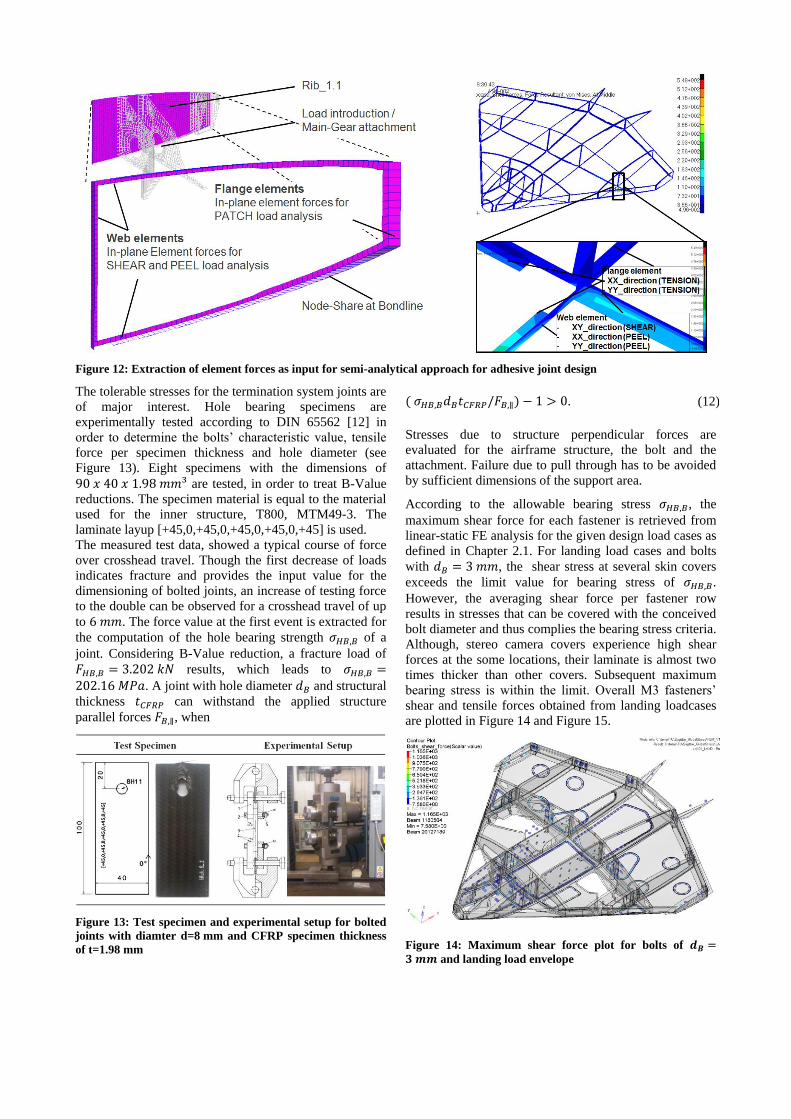
Figure 12: Extraction of element forces as input for semi-analytical approach for adhesive joint design
The tolerable stresses for the termination system joints are
of major interest. Hole bearing specimens are
experimentally tested according to DIN 65562 [12] in
order to determine the bolts’ characteristic value, tensile
force per specimen thickness and hole diameter (see
Figure 13). Eight specimens with the dimensions of
90 𝑥 40 𝑥 1.98 𝑚𝑚³ are tested, in order to treat B-Value
reductions. The specimen material is equal to the material
used for the inner structure, T800, MTM49-3. The
laminate layup [+45,0,+45,0,+45,0,+45,0,+45] is used.
The measured test data, showed a typical course of force
over crosshead travel. Though the first decrease of loads
indicates fracture and provides the input value for the
dimensioning of bolted joints, an increase of testing force
to the double can be observed for a crosshead travel of up
to 6 𝑚𝑚. The force value at the first event is extracted for
the computation of the hole bearing strength 𝜎𝐻𝐵,𝐵 of a
joint. Considering B-Value reduction, a fracture load of
𝐹𝐻𝐵,𝐵 = 3.202 𝑘𝑁 results, which leads to 𝜎𝐻𝐵,𝐵 =202.16 𝑀𝑃𝑎. A joint with hole diameter 𝑑𝐵 and structural
thickness 𝑡𝐶𝐹𝑅𝑃 can withstand the applied structure
parallel forces 𝐹𝐵,∥, when
Figure 13: Test specimen and experimental setup for bolted
joints with diamter d=8 mm and CFRP specimen thickness
of t=1.98 mm
( 𝜎𝐻𝐵,𝐵𝑑𝐵𝑡𝐶𝐹𝑅𝑃/𝐹𝐵,∥) − 1 > 0. (12)
Stresses due to structure perpendicular forces are
evaluated for the airframe structure, the bolt and the
attachment. Failure due to pull through has to be avoided
by sufficient dimensions of the support area.
According to the allowable bearing stress 𝜎𝐻𝐵,𝐵, the
maximum shear force for each fastener is retrieved from
linear-static FE analysis for the given design load cases as
defined in Chapter 2.1. For landing load cases and bolts
with 𝑑𝐵 = 3 𝑚𝑚, the shear stress at several skin covers
exceeds the limit value for bearing stress of 𝜎𝐻𝐵,𝐵.
However, the averaging shear force per fastener row
results in stresses that can be covered with the conceived
bolt diameter and thus complies the bearing stress criteria.
Although, stereo camera covers experience high shear
forces at the some locations, their laminate is almost two
times thicker than other covers. Subsequent maximum
bearing stress is within the limit. Overall M3 fasteners’
shear and tensile forces obtained from landing loadcases
are plotted in Figure 14 and Figure 15.
Figure 14: Maximum shear force plot for bolts of 𝒅𝑩 =𝟑 𝒎𝒎 and landing load envelope

Figure 15: Maximum axial force plot for bolts of 𝒅𝑩 =𝟑 𝒎𝒎 and landing load envelope
4.1.4 Buckling proof
The proof of the aircraft’s structural stability takes all
static and quasi-static load cases into account. First, linear
buckling analysis is processed. Corresponding linear
buckling factors are evaluated for ultimate load level. A
structure is stable when
𝜆 − 1 > 0. (13)
is fulfilled. In the event of occurring critical buckling
factors (𝜆 < 1), a geometrical nonlinear analysis via
quasi-static loads is applied to examine geometrical
stability in the post-buckling regime. With a minimum
linear buckling factor of 0.16, landing loads turned out to
be the most critical load cases, as shown in Figure 16.
However, nonlinear geometrical analysis proved that
those early buckles confine to local corners around cut-
outs, and no structural instability is expected for Ultimate
Load levels (see Figure 17).
Figure 16: Critical buckling mode envelope for landing
loads, 𝝀 = 𝟎. 𝟏𝟔 … 𝟏. 𝟏𝟓
Figure 17: Displacement envelope plot for landing loads
from nonlinear analysis
4.1.5 Aeroelastic stability
Static and dynamic in flight aeroelastic stability, like
divergence, control reversal and flutter, has to be proven
according to the certification specifications CS-23.
Structural damping is assumed to be 0.020 and constant
over frequency. This assumption is justified, by the use of
foam cores in the sandwich panels, as well as the
application of structural bonds, rather than monolithic
parts. The results of the flutter analysis are shown in
terms of damping ratio of the eigenvalues of the
aeroelastic system over air speed. Up to an air speed of
𝑣 = 120 𝑚/𝑠 at sea level, no flutter mode exceeds zero
damping value (cf. Figure 18). Thus, the aircraft is
considered flutter-free as its maximum flight speed is
𝑣𝑚𝑎𝑥 = 100 𝑚/𝑠.
Figure 18: Aeroelastic modal damping vs. air speed
The most critical flutter modes mainly involve the vertical
tail, outboard flaps and skin fields. Flutter modes 34 and
57 are the closest to the minimum flutter speed 1.2𝑣𝑚𝑎𝑥
as derived from Figure 18. The antisymmetric aeroelastic
flutter mode shape is shown exemplarily for mode 34 in
Figure 19.
Figure 19: Aeroelastic mode shape 34

4.2 Verification by structural component
test
In order to verify the simulation results and thereby
evaluate the software and design procedure using MSC
Nastran, a single component is manufactured for physical
testing. First the accordance of the linear elastic behaviour
of experiment and numerical computation is verified. The
examination of the fracture load is done in a subsequent
step. The selected component for the experimental test
has to
be a structural important and highly stressed
component,
possess a representative laminate layup,
ensure that the achievable loads result in strains high
enough to be measured accurately (𝜀 > 1𝑒 − 4) and
with only moderate gradients in highly stressed
regions,
possess a geometry with flat regions, which can be
born reliable and without local overloads and
be of a size, that is conform with the testing
capabilities at DLR Braunschweig.
The selected test specimen, which fulfils these demands,
is Rib1.1_1. The measuring equipment allows to record
local strains in two ways during the test procedure.
Punctual strains, marked in Figure 20 with crosses, are
measured with strain gauges whereas areal strain
information is logged by the 3D camera system GOM
Aramis. The related test forces from the testing machine
are overlaid to be able to compare numerical and
experimental results.
The results of the linear elastic investigations lead to the
following conclusions:
Higher strains in FEM data indicate too small
material values within the FEM simulation for
tension, compression and shear stiffness.
The elastic behaviour of FEM model and
experimental setup is nearly identical and linear but
shows different slopes (see Figure 20).
Deviations up to 60% occur for low load levels, due
to manufacturing accuracy near transitions to rib
flanges and sandwich structures.
Besides the local strain values, the most important
parameter for the evaluation of the numerical design
process is the fracture load. The fracture load was
evaluated as the force of the first event, where the test
forces first decreases for increasing crosshead travel. The
test specimen, component Rib_1.1_1, withstands and
exceeds the predicted fracture loads. The fracture loads lie
between +68% and +138% higher than the simulated
values. These deviations can mainly be explained with the
applied correction factors that are applied to the material
constants and in addition with geometrical inaccuracies at
the critical area near the bearing of the specimens.
Figure 20: Experimental setup and comparison of strains
from numerical and experimental investigations
Figure 21 summarizes the fracture loads that are predicted
by simulations and measured in physical test.
Figure 21: Comparison of experimental and numerical
fracture loads of structural test specimen

5 Manufacturing
5.1 Manufacturing of upper and lower
shell
The main aim during the preparation process for the
manufacturing of both skins of the Sagitta demonstrator is
to keep the areal weight of the shell material as low as
possible. This is particularly important as the chosen
flying wing configuration results in an overall surface
area of approximately nine square meters. Therefore it is
necessary to reach an average areal weight below
1 𝑘𝑔/𝑚² to be able to meet the target weight of 30 𝑘𝑔 for
the assembled airframe including lids and flaps.
Preliminary manufacturing tests show that the resin
uptake of the core material surface is the weight
component that has to be reduced. To perform
comparability, an exemplary stack-up sequence is
determined for manufacturing tests, which is based on the
preliminary sizing results. It is symmetrical and consists
of two skin layers of Textreme prepreg with an aerial
weight of 80 𝑔/𝑚², 48 % resin weight portion on each
side and a 2 𝑚𝑚 core layer. The following table shows
the areal weight of test specimens that were manufactured
using the different Rohacell core materials that are
introduced in chapter 3.1.1.3. Figure 22 shows that a resin
infusion process leads to a tremendous increase of the
resin uptake of the core surface. The best result using a
resin infusion process can be achieved with the Rohacell
RIMA core material. Its fine pored surface leads to an
additional weight of 200 g/m² compared to the specimen
manufactured from prepreg.
Figure 22: Minimum areal weight of an exemplary stack-up
depending on core material and manufacturing process.
Comparing specimen two and specimen five which are
both made from prepreg it can be seen that there is no
difference in the overall areal weight despite the fact that
the Rohacell IGF has larger pores than the Rohacell
RIMA foam. Figure 23 shows a cross section of both
specimens.
Figure 23: Cross section of the exemplary laminate showing
the different porosities of Rohacell RIMA and Rohacell IGF
There occurred one major drawback using a large pored
foam core with thin skin layers made from prepreg.
Depending on the resin weight of the prepreg and the
stack-up the skin laminate may lack resin because of the
resin uptake of the core. This results in an imperfect
impregnation of the skin laminate. For this reason the
Rohacell RIMA foam is chosen as core material for the
shells of the Sagitta demonstrator.
To reduce manufacturing time and tooling costs both
shells are processed in just one step and in one single
tooling including all skin reinforcements, covers and
doors. Figure 24 shows one of the integrally
manufactured maintenance covers of the lower skin. To
do so the plies of the covers and lids are cut net-shape and
preformed with their individual foam core. These
preforms are the first in the laminating process to be put
into the mould. One layer of peel ply between covers and
surrounding skin laminate ensures that they can be
separated after the curing process.
Figure 24: Integrally manufactured cover of the Sagitta
lower skin
As a drawback this totally integral approach leads to
extensive stack-up sequences for both skins. The lower
skin consists of 213 plies. The ply table of the upper skin
counts 336 single plies. For a proper positioning inside
the mould and especially of the door preforms, a laser
projector is mandatory. For weight and therefore handling
reasons and due to the low thermal expansion compared
to aluminium the shell tooling is also made of CFRP. The
curing process took place in an autoclave at up to 100°C
and 5 bar absolute pressure. Both, higher pressure and
higher temperature would improve the quality of the
CFRP laminate but it would also cause the foam core to
collapse during the process due to its limited strength.

Figure 25: Sagitta lower skin in the CFRP tooling after the curing process, covered with the vacuum bagging.
Figure 25 depicts the lower skin inside the CFRP shell
tooling after the autoclave curing. It also shows the large
number of covers and doors that are manufactured in the
same step. One can see in the picture that there is very
little breather used for the vacuum bagging. The reason is
that in fact all surplus resin of the skin plies is necessary
for the interface to the core material. Therefore excessive
bleeding must be prevented.
5.2 Manufacturing of the inner structure
Unlike the shells of the Sagitta demonstrator which are
made from TeXtreme spread tow fabric the inner structure
is made from a regular carbon fibre 2x2 twill fabric
prepreg. The resin system is Cytec MTM49-3 with a resin
weight of 42 % and an areal weight of the fabric of
200 𝑔/𝑚². This material is chosen because of the lack of
drapability of the TeXtreme fabric especially in narrow
moulds. A second reason is that packaging and
preliminary design showed that there have to be hard
points on each of the ribs and spars. This means that a
higher wall thickness is preferable to deal with the
bearing stresses at those points. In this case the Textreme
fabric loses its main advantage which is the ability to
manufacture extremely thin laminates. Rohacell RIMA is
chosen as core material due to the findings concerning the
lower resin uptake during the manufacturing of the shells.
The huge number of individual parts and the resulting
effort lead to a reassessment of the manufacturing
process. To simplify tooling manufacturing and
preproduction of the components of the inner structure
they all do have a c-shape cross section with a draft angle
at the flanges. This enabled the milling of simple flat
moulds. The surrounding flange with the draft angle and
the reinforced web with the cut-outs for the air intakes are
shown at the exemplary component Spar 1 in Figure 26.
One drawback of the board material is the huge thermal
expansion of about 40 ∗ 10−6 𝐾−1 and the related
distortions that occur even at curing temperatures of about
80 °𝐶. Results from preliminary manufacturing tests on
this board material showed that it has to be coated with
paint or resin or sealed with PTFE-film to reduce the
surface roughness of these moulds.
Figure 26: Spar 1 with cut-outs for the jet engine intakes,
enlarged cross section of the sandwich area
Figure 27 shows a microscopic view 500 x enlarged on
the surface of a specimen which was manufactured in a
mould milled from board material. The tooling was sealed
using regular release agent. It depicts the large amount of
dimples with a depth of approximately 0.03 𝑚𝑚.
Figure 27: 500x enlarged microscopic view on the surface of
a CFRP part manufactured in a mould made from board
material
Demoulding of the parts is feasible but the surface
roughness inhibits the sliding of the plies in the mould. As
the tooling expands during the autoclave curing, the plies
peel off in areas of bends or small radii. A minimum
surface roughness for example by using a PTFE-coating
prevents this effect. Metal tooling for example made from
aluminium does have a lower thermal expansion and a
lower surface roughness but the costs per tooling are
significantly higher compared to the board material. To
avoid bridging through the vacuum bagging in the
transition from web to flange neither peel ply nor breather
is applied in those areas. All components were autoclave
cured at 100°C and 5 bar absolute pressure.

Figure 28: Roll-out of Sagitta after structural assembly at the DLR in Brunswick (top, bottom middle, bottom right), Sagitta
at ILA2014, Berlin (bottom left) [13]
5.3 Assembly and integration
Depending on the results of the stress calculation
structural bonding and bolting are applied to assemble the
demonstrator structure. As almost all adhesive joints are
crucial and control of success for adhesive bonds is
limited, bonding processes call for special care. All
bonding surfaces are grinded thoroughly but carefully
prior bonding. Cleanliness of bonding surfaces is
subsequently controlled by means of a water break test.
Adhesive mixing is done in a speed mixer with predefined
parameters to ensure homogenous adhesive properties.
The adhesive is applied manually out of a cartridge.
Novel designed surface distance features are implemented
in low loaded areas within the bondline to guarantee a
minimum bond line thickness. Hence, kissing bonds as
local bond areas with insufficient or even without
adhesive are avoided.
In the first step the leading edge spars are bonded to the
upper skin. After that the assembly sequence goes on with
spar 0 in the front along the x-axis of the airframe up to
the rear spar. The last step of the sequence is closing the
flying wing by applying the second shell. This is
particularly demanding as there are only some small
openings that can be used for inspection of the bonding or
for rework. To ensure the accurate aerodynamic shape a
spare CFRP-mould is used to support the upper skin
during the assembly process. This support is levelled and
aligned to a 3D workbench using 3D measuring
equipment. As the workbench serves as a reference during
the assembly this alignment also ensures the ability to
position all spars and ribs accurately. Figure 29 shows the
Sagitta assembly rig including the support and the 3D
workbench. The components of the inner structure are
placed on the upper skin for a preliminary fitting test.
Figure 29: Assembly rig of the Sagitta demonstrator,
preliminary fitting of the inner structure with the upper
shell
The availability of major components or at least of
dummies for example of the landing gear, the fuel tank
and the jet engines including all ducts is important for the
assembly. The same applies to the whole wiring harness.
The integration of those critical components in this early
phase of the assembly process makes sure that the
components fit and work properly later on.

6 Conclusion
The structure of the Sagitta demonstrator is successfully
designed, proofed by analysis and experimental tests and
finally manufactured. The weight of the structure
including control surfaces, vertical tail, heatshield and
varnish ended up to approximately 36 𝑘𝑔 and amounts to
one quarter of the maximum take-off weight. The
structural analysis evaluates the critical parts for the
different loading conditions.
The most challenging design issues, which had to be
overcome, are identified as the dimensioning of adhesive
joints and the design of the landing gear attachments. A
novel semi-analytical method for dimensioning adhesive
joints is developed, which compares the experimentally
determined strength values analytically with loads that are
extracted from the global FEM model. The reliable
dimensioning of adhesive joints is thus enabled. Landing
loads have turned out to significantly exceed the expected
values, which are determined during preliminary analysis.
Structural modifications had to be applied to better
distribute loads and thus relief the landing gear
attachments and further the related adhesive joints.
With the successful structural proof, the manufacturing
and assembly, the Sagitta structure is ready for integration
and flight test.
The UAV structure is assembled and completed for the
integration phase, in March 2015. In the following the
flight hardware, like landing gear, fuel tank, electronic
components with power supply, actuators and flight
control units are installed and tested. First flights of
Sagitta are scheduled for spring 2016.
7 Acknowledgments
Airbus Defence and Space supports the project Sagitta
with resources and large expertise. The productive
cooperation with the participating research institutes
allowed handling and overcoming even complex and
interdisciplinary issues. The excellent teamwork and
support is gratefully acknowledged.
8 Literature
[1] Hövelmann A. et al.. Experimental investigations on
vortex flow phenomena of a diamond wing
configuration. In 29th Congress of the International
Council of the Aeronautical Sciences, ICAS 2014;
2014; St. Petersburg, Russia. Code 108502.
[2] Frey A. et al.. Überwachungsinstanz zur Trennung
des Missionssystems und des Flugkontrollsystems in
dem unbemannten Luftfahrtsystem SAGITTA. In
Deutscher Luft- und Raumfahrtkongress 2014; 2014;
Augsburg, Germany. urn:nbn:de:101:1-
2014121216572.
[3] Collier Research Corporation. HyperSizer methods
and equations documentation. 2004..
[4] Normenausschuss Kunststoffe. Bestimmung
dynamisch-mechanischer Eigenschaften. Deutsche
Norm. Berlin, Germany: Deutsches Institut für
Normung e.V., Kunststoffe; 2011. Report No.: DIN
EN ISO 6721.
[5] Normenausschuss Materialprüfung. Bestimmung der
Zugscherfestigkeit von Überlappungsklebungen.
Deutsche Norm. Berlin, Germany: Deutsches Institut
für Normung e.V., Klebstoffe; 2009. Report No.:
DIN EN 1465.
[6] Wiedemann J.. Leichtbau, Elemente und
Konstruktion. 3rd ed. Berlin: Springer Verlag; 2007.
[7] Normenausschuss Materialprüfung. Klebstoffe -
Bestimmung des Schälwiderstandes von Klebungen.
Deutsche Norm. Berlin, Germany: Deutsches Institut
für Normung e.V., Klebstoffe; 1995. Report No.:
DIN EN 1464.
[8] Feih S. et al.. Adhesive and composite failure
prediction of single-L joint structures under tensile
loading. International Journal of Adhesion and
Adhesives. 2005 February: 47 - 59.
[9] Habenicht G.. Kleben: Grundlagen, Technologien,
Anwendungen. 5th ed. Berlin: Springer Verlag;
2006.
[10] Airbus. Fiber reinforced plastics - Determination of
joint strength of mechanically fastened joints. Airbus
Test Method. Blagnac, France:, Airbus S.A.S
Engineering directorate; 2009. Report No.: AITM 1-
0065.
[11] Airbus. Fibre reinforced plastics - Determination of
pull-through strength of mechanical joints. Airbus
Test Method. Blagnac, France:, Airbus S.A.S
Engineering directorate; 2011. Report No.: AITM 1-
0066.
[12] Normenstelle Luftfahrt. Prüfung von
multidirektionalen Laminaten, Bestimmung der
Lochleibungsfestigkeit. Deutsche Norm. Berlin,
Germany: Deutsches Institut für Normung e.V.,
Faserverstärkte Kunststoffe; 1991. Report No.: DIN
65562.
[13] AIRBUS Group. Airbus Group - Sagitta: Airbus
Defence and Space open collaboration project.
[Online].; 2015 [cited 2015 August 13. Available
from: http://www.airbusgroup.com/int/en/news-
media/media~item=jcr%3A3095d1f2-a930-4c90-
92b3-087a017f654d~.html.