Design Procedures PowerPoint Presentation - … · ASCE 7-10 ch.17.2.4.6 : ... + 30% E y 17.6.3.3...
13
5/26/2014 1 DAVY SUKAMTA & PARTNERS, Structural Engineers Web: www.davysukamta.com Email: [email protected] Ir.Davy Sukamta, Fellow PE DAVY SUKAMTA & PARTNERS, Structural Engineers DAVY SUKAMTA & PARTNERS, Structural Engineers General Design Approach Superstructure Design Isolation System Design (and Testing) DBE = 2/3MCE Loads may be reduced by seismic reduction factor R R ≤ 2 allowing limited inelastic response MCE R 1%/50 yr = 2475-yr return period + fragility factor No seismic reduction factor DAVY SUKAMTA & PARTNERS, Structural Engineers 17.2.3 Configuration 17.2.4.2 Wind Forces 17.2.4 Isolation System regular or irregular structure 17.2.4.1 Environtmental Conditions 17.2.1: Importance Factor I C = 1.0 (always) Stiffness + 20% Mean value stiffness Stiffness - 20%
-
Upload
vuongtuyen -
Category
Documents
-
view
218 -
download
0
Transcript of Design Procedures PowerPoint Presentation - … · ASCE 7-10 ch.17.2.4.6 : ... + 30% E y 17.6.3.3...

5/26/2014
1
DAVY SUKAMTA & PARTNERS, Structural Engineers
Web: www.davysukamta.comEmail: [email protected]
Ir.Davy Sukamta, Fellow PE
DAVY SUKAMTA & PARTNERS, Structural Engineers
DAVY SUKAMTA & PARTNERS, Structural Engineers
General Design Approach
Superstructure Design
Isolation System Design (and Testing)
DBE = 2/3MCELoads may be reduced by seismic reduction factor RR ≤ 2 allowing limited inelastic response
MCER
1%/50 yr = 2475-yr return period + fragility factorNo seismic reduction factor
DAVY SUKAMTA & PARTNERS, Structural Engineers
17.2.3 Configuration
17.2.4.2 Wind Forces
17.2.4 Isolation System
regular or irregular structure
17.2.4.1 Environtmental Conditions
17.2.1: Importance Factor IC= 1.0 (always)
Stiffness + 20%Mean value stiffnessStiffness - 20%
5/26/2014
2
DAVY SUKAMTA & PARTNERS, Structural Engineers
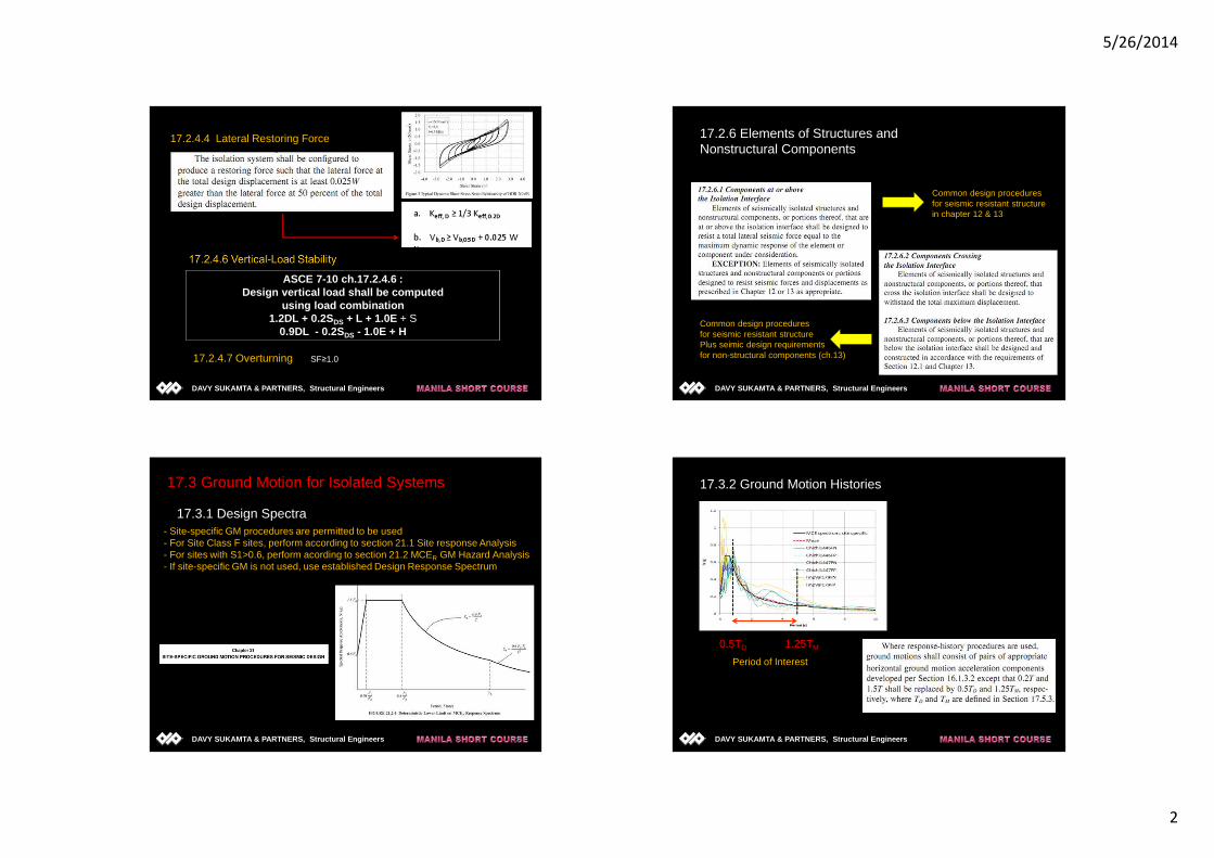
ASCE 7-10 ch.17.2.4.6 :Design vertical load shall be computed
using load combination1.2DL + 0.2SDS + L + 1.0E + S
0.9DL - 0.2SDS - 1.0E + H
17.2.4.4 Lateral Restoring Force
SF≥1.017.2.4.7 Overturning
DAVY SUKAMTA & PARTNERS, Structural Engineers
17.2.6 Elements of Structures andNonstructural Components
Common design proceduresfor seismic resistant structurePlus seimic design requirementsfor non-structural components (ch.13)
Common design proceduresfor seismic resistant structurein chapter 12 & 13
DAVY SUKAMTA & PARTNERS, Structural Engineers
17.3 Ground Motion for Isolated Systems
17.3.1 Design Spectra- Site-specific GM procedures are permitted to be used- For Site Class F sites, perform according to section 21.1 Site response Analysis- For sites with S1>0.6, perform acording to section 21.2 MCER GM Hazard Analysis- If site-specific GM is not used, use established Design Response Spectrum
DAVY SUKAMTA & PARTNERS, Structural Engineers
17.3.2 Ground Motion Histories
0.5TD 1.25TM
Period of Interest

5/26/2014
3
DAVY SUKAMTA & PARTNERS, Structural Engineers
DESIGN METHODS /Analysis Procedures
Static Analysis Dynamic Analysis
Response SpectrumAnalysis
Time HistoryAnalysis
Ch.17.4
Equivalent Lateral ForceProcedures
DAVY SUKAMTA & PARTNERS, Structural Engineers
Other limitation forbase isolation system
Structures does nothave irregularrities
TD ≥ 3 Tfixed-base
S1 < 0.60 g
Tm ≤ 3.0 sec
H ≤ 4 stories or 19.8 m
Site Class A, B, C or D
Static AnalysisCh.17.4.1
DAVYSUKAMTA & PARTNERSStructural Engineers
Equivalent Lateral Force Procedures
Point 7: The isolation system meets all of the following criteria

5/26/2014
4
DAVYSUKAMTA & PARTNERSStructural Engineers
Dynamic Analysis
Response SpectrumAnalysis
Time HistoryAnalysis
Site class A, B, C dan D
Isolation system must meet the criteria of point 7, ch. 17.4.1
No Limitation on Use
100% Ex + 100% Ey
17.5 Equivalent Lateral Force Procedure
17.5.3 Minimum Lateral Displacement
17.5.2 Deformation Characteristics of the Isolation System
17.5.4 Minimum Lateral Force
17.5.5 Vertical Distribution of Force
17.5.6 Drift Limits

5/26/2014
5
DAVY SUKAMTA & PARTNERS, Structural Engineers
DBTDgSDDD
241
π=
D
DDD
B
TgSD2
1
4π=
17.5.3.1
See Table 17.5-1 Damping Coefficient
DAVY SUKAMTA & PARTNERS, Structural Engineers
2/3MCE
DAVYSUKAMTA & PARTNERSStructural Engineers
ASCE 7-10 Table 17.5-1
DAVY SUKAMTA & PARTNERS, Structural Engineers
gk
WTD
D
min
2π=
17.5.3.2
5/26/2014
6
DAVY SUKAMTA & PARTNERS, Structural Engineers
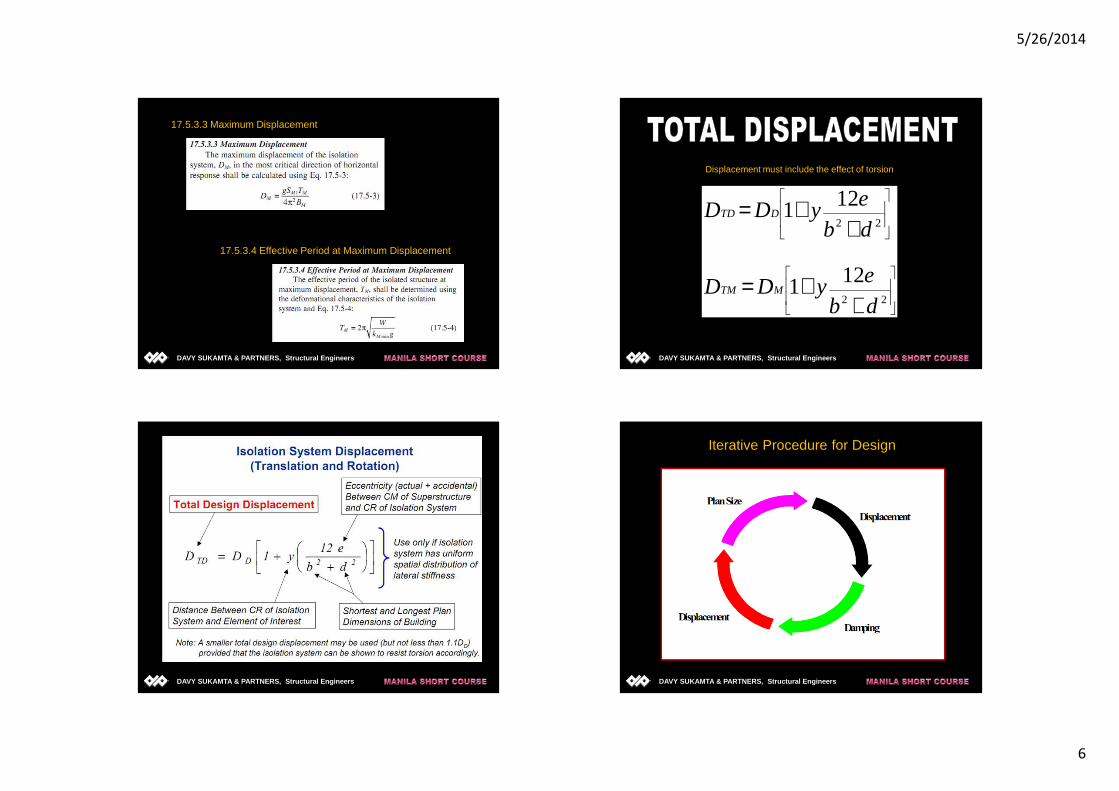
17.5.3.3 Maximum Displacement
17.5.3.4 Effective Period at Maximum Displacement
DAVY SUKAMTA & PARTNERS, Structural Engineers
++=
++=
22
22
121
121
db
eyDD
db
eyDD
MTM
DTD
Displacement must include the effect of torsion
DAVY SUKAMTA & PARTNERS, Structural Engineers DAVY SUKAMTA & PARTNERS, Structural Engineers
Iterative Procedure for Design

5/26/2014
7
DAVY SUKAMTA & PARTNERS, Structural Engineers
17.5.4 Minimum Lateral Forces
Vb
= kDmax
DD
17.5.4.2: above the isolation system
VS
=
DAVY SUKAMTA & PARTNERS, Structural Engineers
Isolation Interface
Isolation System
1R
VV bS =
DD DkVb max=
DAVY SUKAMTA & PARTNERS, Structural Engineers
17.5.5 Vertical Distribution of Force
The shear force Vs shall be distributed over theheight of the structure above the isolation interfaceusing Eg. 17.5-9:
DAVY SUKAMTA & PARTNERS, Structural Engineers
17.5.6 Drift Limits

5/26/2014
8
DAVYSUKAMTA & PARTNERSStructural Engineers
17.6 Dynamic Analysis Procedures
DAVYSUKAMTA & PARTNERSStructural Engineers
Isolated Structure
Isolation System
17.6.2 Modelling
DAVYSUKAMTA & PARTNERSStructural Engineers
17.6.3 Description of Procedures
17.6.3.2 Input Earthquake
For isolation system: - use DBE to calculate the total design displacement- use MCE to calculate the total maximum displacement
For isolated structure:- use DBE to calculate lateral forces and displacements
DBE = 2/3 MCE
DAVYSUKAMTA & PARTNERSStructural Engineers
100Ex
+ 30% Ey
17.6.3.3 Response-Spectrum Procedures
≥Static analysis result in that story

5/26/2014
9
DAVYSUKAMTA & PARTNERSStructural Engineers
17.6.3.4 Response-History Procedures
A suite of not fewer than three pairs ofappropriate ground motions shall be used
The ground motion pairs shall be selected and scaled in accordance with sect. 17.3.2
Event Characteristic Magnitude,Mw
Distance(km)
ScaleFactor
PGA (g) Source
Chi Chi
(1999)
Megathrust zone 7.62 117 5.3 0.18 PEER
Chi Chi
(1999)
Benioff zone 7.62 118 5.7 0.26 PEER
Imperial
Valley(1994)
Shallow crustal 6.50 25 1.0 0.42 PEER
Period of interest
DAVYSUKAMTA & PARTNERSStructural Engineers
Ground Motions / Time SeriesFor 3-D Analysis
-Selected GM must represent theEQ mechanism
-Scaled for the period of interest
DAVYSUKAMTA & PARTNERSStructural Engineers
Selected Ground Motion
Period of interest
DAVYSUKAMTA & PARTNERSStructural Engineers
Event Characteristic Magnitude,Mw
Distance (km) ScaleFactor
PGA (g) Source
Chi Chi (1999) Megathrust zone 7.62 117 5.3 0.18 PEER
Chi Chi (1999) Benioff zone 7.62 118 5.7 0.26 PEER
Imperial
Valley(1994)
Shallow crustal 6.50 25 1.0 0.42 PEER
Selected Ground Motion

5/26/2014
10
DAVYSUKAMTA & PARTNERSStructural Engineers
17.6.3.4 Response-History Procedures
17.6.4.2 Structural Elements above the Isolation System….use R1 from section 17.5.4.2….regular configuration V>80%VSEXCEPTION:RSA + response-Spectrum Procedures, 80%VS> V > 60%VS
17.6.4.1 Isolation System and Structural Elementsbelow the isolation System
….design lateral force shall not be takenas less than 90% of V B (Eq. 17.5-7)….total design displacement > 90% DTD….total maximum displacement> 80% DTM
Analysis Analysis Analysis Analysis ---- ModelingModelingModelingModelingGudang Garam TowerGudang Garam TowerGudang Garam TowerGudang Garam Tower
DAVYSUKAMTA & PARTNERSStructural Engineers
17.6.4 Minimum Lateral Displacement and Forces
17.6.4.1 Isolation System and Structural Elementsbelow the isolation System
….design lateral force shall not be takenas less than 90% of V B (Eq. 17.5-7)….total design displacement > 90% DTD….total maximum displacement> 80% DTM
17.6.4.2 Structural Elements above the Isolation System….use R1 from section 17.5.4.2….regular configuration V ≥ 80%VS and V ≥ sect.17.5.4.3
EXCEPTION:NLRHA procedures for regular structure 80%VS ≥ V ≥ 60%VSLRSA procedures for irregular structure V≥VS or 17.5.4.3NLRHA procedures for irregular structure VS ≥ V ≥ 80%VS
DAVYSUKAMTA & PARTNERSStructural Engineers
17.6.4.4 Drift Limits
17.6.4.3 Scaling of Results

5/26/2014
11
DAVYSUKAMTA & PARTNERSStructural Engineers
17.7 Design Review
DAVYSUKAMTA & PARTNERSStructural Engineers
17.8 Testing
DAVY SUKAMTA & PARTNERS, Structural Engineers DAVYSUKAMTA & PARTNERSStructural Engineers

5/26/2014
12
DAVY SUKAMTA & PARTNERS, Structural Engineers DAVYSUKAMTA & PARTNERSStructural Engineers
At the Design Displacement
At the Maximum Displacement
17.8.5.1 Maximum and Minimum Effective Stiffness
DAVYSUKAMTA & PARTNERSStructural Engineers
17.8.5.2 Effective Damping
DAVYSUKAMTA & PARTNERSStructural Engineers
16.2.2 Modeling
- Represent spatial distribution of mass- Model for the hysteretic behavior of elements
shall be consistent with lab test data

5/26/2014
13
DAVY SUKAMTA & PARTNERS, Structural Engineers
http://www.davysukamta.com
TTTTHANK YOUHANK YOUHANK YOUHANK YOU
News / Articles


![[PPT]PowerPoint Presentation · Web viewEmergency Procedures Training For Students, Faculty & Staff This presentation will provide you with information, procedures and tips on what](https://static.fdocuments.net/doc/165x107/5ae9b8b67f8b9a585f8b67a1/pptpowerpoint-presentation-viewemergency-procedures-training-for-students-faculty.jpg)