Design Optimization of B-Pillar for Sustaining Roof Crush Test … · · 2016-09-14load is...
27
Page 1 Innovation Intelligence ® Design Optimization of B-Pillar for Sustaining Roof Crush Test Prof Tae Hee Lee Sung Sik Choi (Masters Program) Amalnerkar Eshan(Masters Program) Hanyang University Department of Automotive Engineering Sensitivity Analysis and Design Innovation (SANDI)
Transcript of Design Optimization of B-Pillar for Sustaining Roof Crush Test … · · 2016-09-14load is...

Page 1
Innovation Intelligence®
Design Optimization of B-Pillar for Sustaining
Roof Crush Test
Prof Tae Hee Lee
Sung Sik Choi (Masters Program)
Amalnerkar Eshan(Masters Program)
Hanyang University
Department of Automotive Engineering
Sensitivity Analysis and Design Innovation
(SANDI)

Page 2
Copyright © 2012 Altair Engineering, Inc. Proprietary and Confidential. All rights reserved.
Contents
Study Overview
Aim of Research
B-Pillar : Design Inspiration
B-Pillar : FEM Model
B-Pillar : Analysis Condition
Concept Design : Topology Optimization
Morphing using Hypermorph
Batch Job
Optimization (High fidelity)
Screening & Metamodel
Optimization (Metamodel)
Summary
Conclusion

Page 3
Copyright © 2012 Altair Engineering, Inc. Proprietary and Confidential. All rights reserved.
Study overview- Accidents due to rollovers
Accidents due to rollovers constitutes one of the large proportions of injury producing collisions for vehicles.
According to
latest NHTSA
data, nearly 35%
of all deaths
from passenger
vehicle crashes
are cause due to
rollovers.
Source:
*) Advanced Technologies: the Pathway to Total Safety. International Technical conference On Enhanced Safety of Vehicle, May 19,2003
Retrieved from: http://www-nrd.nhtsa.dot.gov/departments/esv/18th/discussions/JK_ESVAdv.htm
Vehicle damage in rollover crashes include:
- deformation of the roof and its supporting structures
- head and neck injuries to the occupants.
Relevant regulation for roof strength is based on
US Federal Motor Vehicle Safety Standard (FMVSS)
216,Roof Crush Resistance, Passenger Cars.
*) Dummy inside a car undergoing roof crush test

Page 4
Copyright © 2012 Altair Engineering, Inc. Proprietary and Confidential. All rights reserved.
Study overview- Test regulation & B-Pillar
Statement
- Force applied is 1.5 times unloaded vehicle weight ,but should not exceed 22,240 N for passenger cars.
- Deformation of test device must not move more than 127mm.
FMVSS 216, Roof Crush Resistance, Passenger Cars
**) Test Device Orientation
*) Actual Test Device
Source:
*) Standard No. 216;Roof Crush Resistance
Retrieved from http://www.fmcsa.dot.gov/rules-regulations/administration/fmcsr/fmcsrruletext.aspx?reg=571.216
**) Insurance Institute For Highway Safety [IIHS] performing Rollover Test Procedure.
Retrieved from: http://wot.motortrend.com/watch-iihs-perform-rollover-crash-test-on-mkz-335i-372031.html#axzz2a8iF5gDp
***) General example of B-Pillar of Ford Mondeo. Retrieved from; http://boronextrication.com/tag/ford/
B-Pillars are safety-relevant parts and essential load carrying elements for achieving roof strength
B-Pillar - Vertical support between a car’s front door window and rear side window
***) Typical car B-Pillar
Page 5
Copyright © 2012 Altair Engineering, Inc. Proprietary and Confidential. All rights reserved.
Aim of Research
The current styling trend towards slimmer B-Pillar results in numerous conflicting
requirements to be met with new concepts, innovative materials and manufacturing
processes.
Thus our aim is to..
Check B-Pillar strength by given analysis condition.
[Tool used- Radioss]
Use reinforced materials [Aluminum foam] to dampen the intensity of load.
[Tool used- Radioss]
Conduct topology optimization to reduce volume of the reinforced material.
[Tool used - Optistruct]
Use morphing process to achieve improved designs with minimum element distortion. [Tool used - Hypermorph]
Conduct high fidelity optimization using batch job technique to obtain better results. [Tool used - Radioss & Matlab]
Perform optimization using Kriging metamodel for comparison.
[Tool used - Radioss & Matlab]
Obtain, an optimized design for B-Pillar using the above process
Page 6
Copyright © 2012 Altair Engineering, Inc. Proprietary and Confidential. All rights reserved.
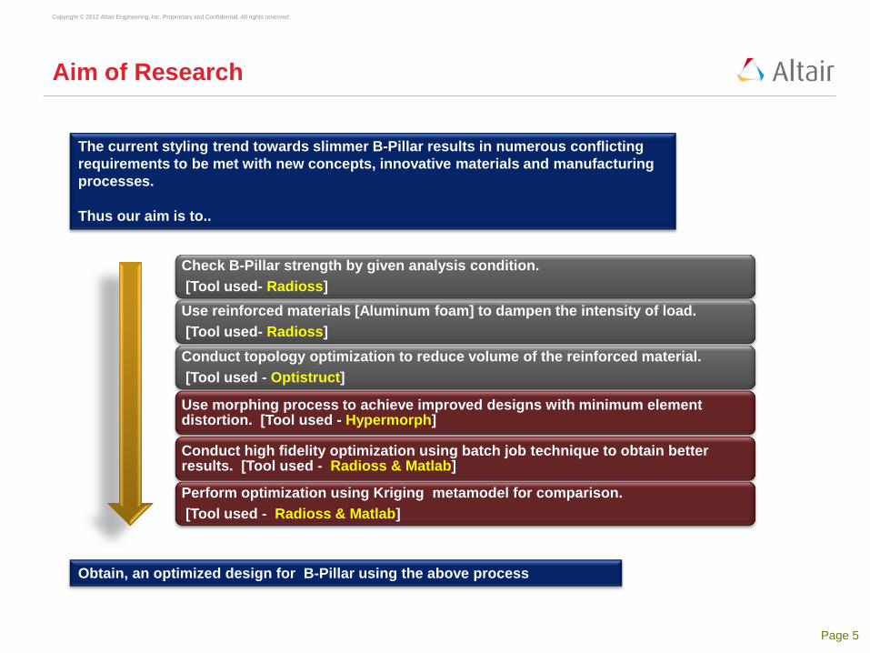
B-pillar : Design Inspiration
*) outer hat section of B-pillar **) Inner hat section of B-Pillar Designed CAD model
Source;
*) **)Thor Fraser, Darren Goldenberg, Muhammad Yazid Mat Isa, Alex Steinhauser, “Design of Automotive Center
Pillar Reinforcement to Resist Roof Crush in F-Series Crew Cab”, Final Report ME 450: Design and Manufacturing III ,Fall 2007
Ford F-150 SUV
Page 7
Copyright © 2012 Altair Engineering, Inc. Proprietary and Confidential. All rights reserved.
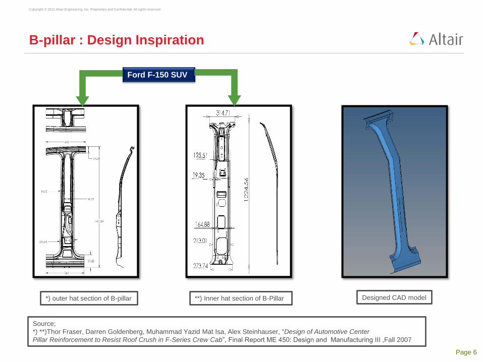
B-Pillar : FEM Model
Color Part Material
Properties
Element Type Number Of
Elements Young’s
Modulus [
N/mm2]
Poisson’s
Ratio
Density
[kg/mm3]
Outer Pillar
[Shell] Steel 2.1e5 0.3 7.9e-9
Mixed
[Quad4 +Tria3]
8753
[8716+37] Inner Pillar
[Shell] Steel 2.1e5 0.3 7.9e-9
Foam
[Solid] AA 6063 8e4 0.33 2.7e-9 Tetra 10997
Weld - - - - Hexa 18
Exploded view of designed B-Pillar
The Aluminum Foam is
connected to the inner and
outer surface using weld
joints at specific locations
Weld joints
Total number of elements = 19768 < 20000 [Required condition is satisfied]
Total=19768

Page 8
Copyright © 2012 Altair Engineering, Inc. Proprietary and Confidential. All rights reserved.
B-Pillar : Analysis Condition
Assumptions:
1. Point of application of force is
fixed.
2. Maximum displacement is at the
bend of B-Pillar structure.
Z-axis Fixed
Reasons for considering the displacement at the bend of B-Pillar-
1. Instead of assuming the full structure of roof and related parts
connected to it, our focus is mainly on B-Pillar. So, the point at which the
load is applied is fixed unlike in the actual roof crush test where it is not
fixed.
2. Also, in the test, the deformation is restricted up to 127mm for whole
roof and adjoining pillar structure. Whereas, in our case, impact is on the
B-Pillar only, so ideal deformation assumed is of 38mm.
Hypermesh Model with
applied load and Boundary
Conditions
*) Thor Fraser, Darren Goldenberg, Muhammad Yazid Mat Isa, Alex Steinhauser, “Design of Automotive Center
Pillar Reinforcement to Resist Roof Crush in F-Series Crew Cab”, Final Report ME 450: Design and Manufacturing III ,Fall 2007
Load
Condition Value Direction
Force [FMVSS 216]
*) 22500 N
(Negative) Y-axis
25° Roll in Z-axis
5° Pitch in X-axis
Boundary
conditions Fixed
Upper : Z-axis
Lower : X,Y and Z-axis

Page 9
Copyright © 2012 Altair Engineering, Inc. Proprietary and Confidential. All rights reserved.
B-Pillar : Analysis Results
Deformation of the B-Pillar with Foam Deformation of B-Pillar without Foam
Maximum Displacement
at Bend of B-Pillar
Without Foam With Foam
[Full reinforced]
68 mm 12 mm
Page 10
Copyright © 2012 Altair Engineering, Inc. Proprietary and Confidential. All rights reserved.
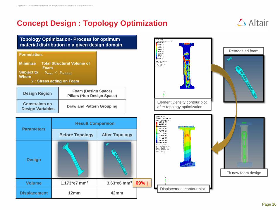
Concept Design : Topology Optimization
Design Region Foam (Design Space)
Pillars (Non-Design Space)
Constraints on
Design Variables Draw and Pattern Grouping
Element Density contour plot
after topology optimization
Remodeled foam
Fit new foam design
Displacement contour plot
Topology Optimization- Process for optimum
material distribution in a given design domain.
Parameters
Result Comparison
Before Topology After Topology
Design
Volume 1.173*e7 mm3 3.63*e6 mm3
Displacement 12mm 42mm
69% ↓

Page 11
Copyright © 2012 Altair Engineering, Inc. Proprietary and Confidential. All rights reserved.
Morphing using Hypermorph
Variable Position Parameter Range
(mm)
X1 Pos1, Pos2,
Pos3 Translate_X [-50,+50]
X2 Pos2 Width_X [-50,+50]
X3 Pos3 Width_X [-30,+30]
X4 Pos4 Width_X [-30,+30]
X5 Pos5 Width_X [-30,+30]
X6 Pos4, Pos5,
Pos6 Translate_X [-30,+30]
X7 Pos7 Width_Z [-20,+20]
X8 Pos8 Width_Z [-20,+20]
Hypermorph:
- easy to use mesh
manipulation tool
- quickly stretch any finite
element mesh while keeping
mesh distortion at minimum.
- It only changes the nodal
location.
- Nodal id or element id remain
unchanged.
Handles and positions of inner pillar Handles and positions of outer pillar

Page 12
Copyright © 2012 Altair Engineering, Inc. Proprietary and Confidential. All rights reserved.
Morphing using Hypermorph - Example
For variable X1(Pos 1/2/3 translation of X axis, morphing process is undertaken
Magnitude of translation= +50
Displacement = 41.315 mm Magnitude of translation= -50
Displacement = 44.987 mm
Magnitude of translation= 0
Displacement = 43.003 mm
Response
- Displacement : Magnitude of displacement vector at no.223705 node

Page 13
Copyright © 2012 Altair Engineering, Inc. Proprietary and Confidential. All rights reserved.
Batch Job
MATLAB
Batch command
HyperMesh
Original model
Applied loads and BCs
1cycle of batch job
Purpose- Combine Hyperworks and Matlab processes to achieve automatically
about the responses obtained from the morphing process
Load original
FE model from
HyperMesh
Define input
variables using
Hypermorph
Save modified
FE model
Achieve responses
(volume, stress,
displacement)
Run RADIOSS
for FE analysis

Page 14
Copyright © 2012 Altair Engineering, Inc. Proprietary and Confidential. All rights reserved.
Optimization (High fidelity)
Optimization [High fidelity]
Formulation
Optimizer – fmincon (SQP)
F - calls 760 calls
Running Time 4.2 hours
Unit time 20 sec
127mm) of (30% 38mm Disp
MPa1202
240
factorsafety
S S
MPa2852
570
factorsafety
S SWhere,
38mmDisp
MPa120S
MPa285S Subject to
Volume Minimize
aluminium ultimate,
foam critical,
steel ultimate,
pillar critical,
foammax,
pillarmax,

Page 15
Copyright © 2012 Altair Engineering, Inc. Proprietary and Confidential. All rights reserved.
Responses
Designs
Improvement Initial
topology model
Optimization
[High fidelity]
Displacement (mm)
[Node ID=223705] 42 [NG] 38 9.5%
Maximum stress (N/mm²): Pillar 293.5 [NG] 285 4.6%
Maximum stress (N/mm²): Foam 4.8 7.2 -
Volume (mm³) 5.15*e6 5.093*e6 1.1%
Optimization Results( High fidelity )
Variable
Magnitude
Initial topology model Optimization
[High fidelity]
X1 [mm] 0 -0.515
X2 [mm] 0 50.000
X3 [mm] 0 -23.908
X4 [mm] 0 -29.998
X5 [mm] 0 -29.995
X6 [mm] 0 2.985
X7 [mm] 0 20.000
X8 [mm] 0 -14.487 Optimized Model

Page 16
Copyright © 2012 Altair Engineering, Inc. Proprietary and Confidential. All rights reserved.
Screening & Metamodel
ANOVA from DOE by
orthogonal array
(8 variables, 27 sample point)
Response: Displacement Response: Max stress Response: Volume
DOE for building Kriging metamodel
by Full Factorial Design
(5 variables, 4 levels,
1024 sample point)
ex) 2 variables 4 levels FFD
Validation for evaluating the accuracy
of Kriging metamodel
(50 points by random sampling)
RMSE [%] R²
Displacement 1.462 0.979
Max stress 0.406 0.948
Volume 0.342 0.998
8 variables → 5 variables

Page 17
Copyright © 2012 Altair Engineering, Inc. Proprietary and Confidential. All rights reserved.
Optimization (Metamodeling)
Optimization using Kriging Metamodel
Hypermesh model after
metamodeling
Validation Result
High
Fidelity
Meta
model
X1 (mm) -8.774
X2 (mm) -46.917
X4 (mm) -30
X7 (mm) 20.000
X8 (mm) 0.131
Displacement
(mm) 37.671 38(0.76%)
Max Stress
[Pillar] (N/mm²) 287.2 285(0.87%)
Max Stress
[Foam] (N/mm²) 7.2 -
Volume (mm³) 4.796 x e6 4.833 x e6
(0.77%)
※ ( %) : Relative Error
F - calls 148 calls
Running
Time 33 sec
Unit time 0.22 sec
38mmDisp
MPa120S
MPa285S Subject to
Volume Minimize
foammax,
pillarmax,

Page 18
Copyright © 2012 Altair Engineering, Inc. Proprietary and Confidential. All rights reserved.
Metamodel
for calculating
responses
-6 -4 -2 0 2 4 6 8 10 12 140
0.05
0.1
0.15
0.2
0.25
PDF of MCS
Reliability
Reliability
analysis
Why metamodel?
Fast
Reliability Analysis is possible !
Optimization result High Fidelity
Model Metamodel
F - calls 750 calls 148 calls
Running Time 4.16 hours 33 sec
Unit time 20 sec 0.22 sec
Reliability Based Design Optimization is possible !
Design variables
Reliability
constraint
Probability of Failure
Response
]/[stressMax 285)(
][ntdisplacemeMax 38)(
95.0,3,2,1,)0)((toSubject
VolumenimizemiTo
)5,4,3,2,1(Find
2
2
1
mmNXG
mmXG
RjRXGR
ix
gettargettar
j
i

Page 19
Copyright © 2012 Altair Engineering, Inc. Proprietary and Confidential. All rights reserved.
Summary
Responses
Designs
Without foam With foam
[Full reinforced] Initial topology
Optimization
[High fidelity]
Optimization
[Metamodel]
Displacement (mm)
(node id = 223705) 68 12 42 38 37.7
Maximum stress
(N/mm²) 390 Very stiff 293.5 285 287.2
Volume (mm³) 1.525*e6 1.326*e7 5.15*e6 5.093*e6 4.796*e6
Model Designs
Efficient use of the material of Aluminum Foam to dampen the intensity of load
Improved Roof Crush Strength by achieving less deformation in the new design
Maximum Stress levels are maintained within the limits
Volume reduced considerably when compared to full foam B-Pillar
Page 20
Copyright © 2012 Altair Engineering, Inc. Proprietary and Confidential. All rights reserved.
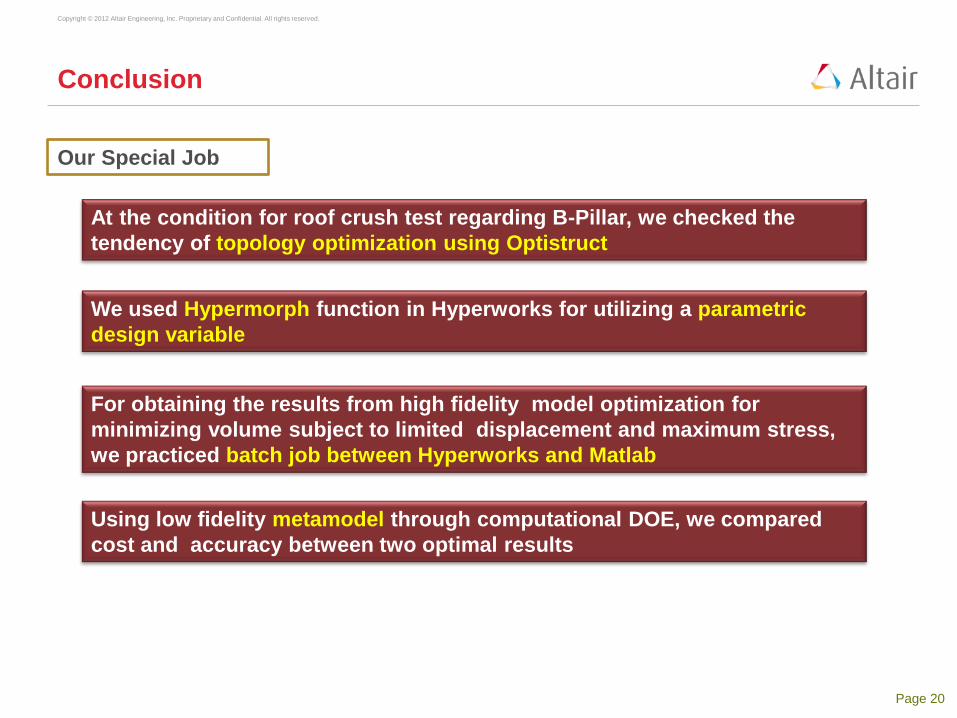
Conclusion
At the condition for roof crush test regarding B-Pillar, we checked the
tendency of topology optimization using Optistruct
We used Hypermorph function in Hyperworks for utilizing a parametric
design variable
For obtaining the results from high fidelity model optimization for
minimizing volume subject to limited displacement and maximum stress,
we practiced batch job between Hyperworks and Matlab
Using low fidelity metamodel through computational DOE, we compared
cost and accuracy between two optimal results
Our Special Job

Page 21
Copyright © 2012 Altair Engineering, Inc. Proprietary and Confidential. All rights reserved.
Q & A

Page 22
Copyright © 2012 Altair Engineering, Inc. Proprietary and Confidential. All rights reserved.
Back data
Page 23
Copyright © 2012 Altair Engineering, Inc. Proprietary and Confidential. All rights reserved.
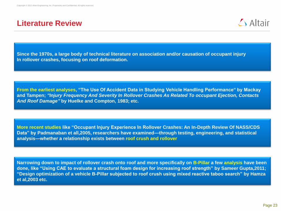
Literature Review
Since the 1970s, a large body of technical literature on association and/or causation of occupant injury
In rollover crashes, focusing on roof deformation.
Narrowing down to impact of rollover crash onto roof and more specifically on B-Pillar a few analysis have been
done, like “Using CAE to evaluate a structural foam design for increasing roof strength” by Sameer Gupta,2011;
“Design optimization of a vehicle B-Pillar subjected to roof crush using mixed reactive taboo search” by Hamza
et al,2003 etc.
More recent studies like “Occupant Injury Experience In Rollover Crashes: An In-Depth Review Of NASS/CDS
Data” by Padmanaban et all,2005, researchers have examined—through testing, engineering, and statistical
analysis—whether a relationship exists between roof crush and rollover
From the earliest analyses, “The Use Of Accident Data in Studying Vehicle Handling Performance“ by Mackay
and Tampen; “Injury Frequency And Severity In Rollover Crashes As Related To occupant Ejection, Contacts
And Roof Damage” by Huelke and Compton, 1983; etc.

Page 24
Copyright © 2012 Altair Engineering, Inc. Proprietary and Confidential. All rights reserved.
References
1) Altair Engineering, Inc., Altair Hyperworks Manual, Altair Engineering, Inc.
2) Altair Engineering, Inc., Optistruct Optimization Manual, Altair Engineering, Inc.
3) Thor Fraser, Darren Goldenberg, Muhammad Yazid Mat Isa, Alex Steinhauser, “Design of Automotive Center
Pillar Reinforcement to Resist Roof Crush in F-Series Crew Cab”, Final Report ME 450: Design and
Manufacturing III ,Fall 2007.
4) J. Christensen, C. Bastien and M.V. Blundell(2012), ‘Effects of roof crush loading scenario upon body in
white using topology optimization’, Coventry University, International Journal of Crashworthiness,
17:1, 29-38,2013.
5) Sameer Gupta, ‘Using CAE to evaluate a structural foam design for increasing roof strength’, Honda R&D,
Americas, Inc., 21001 State Route 739, Raymond, OH 43067-9705, 8th European LS-DYNA Users
Conference,2011.
6) Marco Danti, Maurizio Meneguzzo, Raffaele Saponaro, Izabela Kowarska, ‘Multi-objective Optimization in
Vehicle Concept Modeling’ , Italy, Proceedings of ISMA2010 including USD2010,2010.

Page 25
Copyright © 2012 Altair Engineering, Inc. Proprietary and Confidential. All rights reserved.
Background
Vehicle damage in rollover crashes include:
- deformation of the roof and its supporting structures
- head and neck injuries to the occupants.
Hence, strengthening of the roof is suggested as
an appropriate countermeasure for such fatalities.
Relevant regulation for roof strength is based on
US Federal Motor Vehicle Safety Standard (FMVSS)
216,Roof Crush Resistance, Passenger Cars.
Figure 1. Dummy inside a car undergoing roof crush test
Figure 2. Common rollover crash
Source: Figure 1. Insurance Institute For Highway Safety [IIHS] performing Rollover Test Procedure.
Retrieved from: http://wot.motortrend.com/watch-iihs-perform-rollover-crash-test-on-mkz-335i-372031.html#axzz2a8iF5gDp
Page 26
Copyright © 2012 Altair Engineering, Inc. Proprietary and Confidential. All rights reserved.
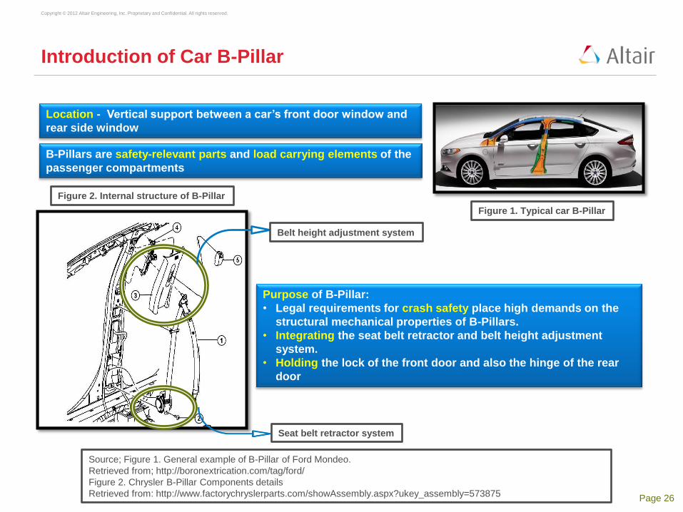
Introduction of Car B-Pillar
B-Pillars are safety-relevant parts and load carrying elements of the
passenger compartments
Location - Vertical support between a car’s front door window and
rear side window
Purpose of B-Pillar:
• Legal requirements for crash safety place high demands on the
structural mechanical properties of B-Pillars.
• Integrating the seat belt retractor and belt height adjustment
system.
• Holding the lock of the front door and also the hinge of the rear
door
Figure 1. Typical car B-Pillar
Belt height adjustment system
Seat belt retractor system
Figure 2. Internal structure of B-Pillar
Source; Figure 1. General example of B-Pillar of Ford Mondeo.
Retrieved from; http://boronextrication.com/tag/ford/
Figure 2. Chrysler B-Pillar Components details
Retrieved from: http://www.factorychryslerparts.com/showAssembly.aspx?ukey_assembly=573875
Page 27
Copyright © 2012 Altair Engineering, Inc. Proprietary and Confidential. All rights reserved.
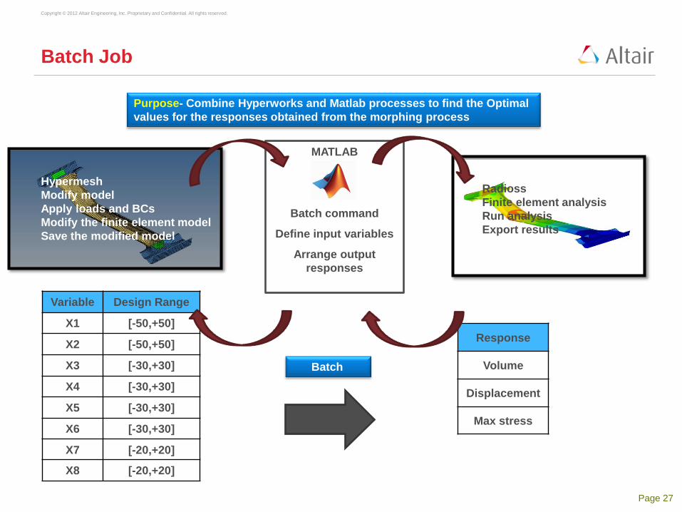
Batch Job
MATLAB
Batch command
Define input variables
Arrange output
responses
Hypermesh
Modify model
Apply loads and BCs
Modify the finite element model
Save the modified model
Radioss
Finite element analysis
Run analysis
Export results
Variable Design Range
X1 [-50,+50]
X2 [-50,+50]
X3 [-30,+30]
X4 [-30,+30]
X5 [-30,+30]
X6 [-30,+30]
X7 [-20,+20]
X8 [-20,+20]
Batch
Response
Volume
Displacement
Max stress
Purpose- Combine Hyperworks and Matlab processes to find the Optimal
values for the responses obtained from the morphing process