DESIGN OF THE GATEWAY BRIDGE, A SKEWED ARCH FOR THE...
12
DESIGN OF THE GATEWAY BRIDGE, A SKEWED ARCH FOR THE A465 HEADS OF THE VALLEYS SCHEME T. Argyle, R. Mitchell Atkins, Transportation, Epsom, UK. e-mails: [email protected], [email protected] SUMMARY As part of the A465 Heads of the Valleys road improvement scheme a new 90m span steel arch bridge with suspended steel composite deck is to be constructed across the River Clydach gorge. The intention is to provide a feature structure as part of the scheme due to the structures location at the ‘gateway’ to the Brecon Beacons National Park, with the A465 mainline crossing into the park at this point. This paper discusses the purpose of the Gateway Bridge as a feature structure on the scheme, the design of the cable arrangement for the constraints imposed by the skewed arch, the arch steelwork design to the requirements of EN 1993 and the impact of the construction methodology on the design including the procedure for ensuring the desired hanger forces are achieved during construction. Keywords: Feature Structure, Steel Arch, Skewed Arch, Cable Supported Structures, Eurocodes, 3D Modelling. 1. INTRODUCTION The Gateway Bridge carries the new two lane single carriageway Brynmawr junction link road over the split level A465, junction sliproads, River Clydach, Clydach Gorge designated geological Site of Special Scientific Interest and a national cycle route. The design was carried out by Atkins for the design and build contractor Costain with architectural input from Knights Architects. The bridge design was completed in early 2016 and the structure is currently under and the structure is currently under construction. Fig. 1 is a visualisation of the completed bridge used during the public enquiry. The Gateway Bridge is a single span thrust arch bridge. The single arch rises 50m above the valley floor and 25m above the deck at the crown, spanning over the deck at a skew of 15°. The bridge deck and arch are to be fabricated from S355 weathering steel. The longitudinally stiffened rectangular arch section has a varying cross section, 3x3m at the base tapering to 3x1.5 m at the crown. The composite ladder beam deck is supported by 22 fully locked coil cables along its length. At the deck level these cables are attached to outriggers at 7.5 m centres to allow sufficient clearance to the structure free zone around the carriageway. At the arch the cables are connected to external lug plates with internal stiffening inside the arch. Fig. 2 is a general arrangement of the Gateway Bridge. 449 8 th International Conference on Arch Bridges October 5-7, 2016, Wrocław, Poland
Transcript of DESIGN OF THE GATEWAY BRIDGE, A SKEWED ARCH FOR THE...

DESIGN OF THE GATEWAY BRIDGE, A SKEWED ARCH FOR THE A465 HEADS OF THE VALLEYS SCHEME T. Argyle, R. Mitchell Atkins, Transportation, Epsom, UK. e-mails: [email protected], [email protected] SUMMARY As part of the A465 Heads of the Valleys road improvement scheme a new 90m span steel arch bridge with suspended steel composite deck is to be constructed across the River Clydach gorge. The intention is to provide a feature structure as part of the scheme due to the structures location at the ‘gateway’ to the Brecon Beacons National Park, with the A465 mainline crossing into the park at this point. This paper discusses the purpose of the Gateway Bridge as a feature structure on the scheme, the design of the cable arrangement for the constraints imposed by the skewed arch, the arch steelwork design to the requirements of EN 1993 and the impact of the construction methodology on the design including the procedure for ensuring the desired hanger forces are achieved during construction. Keywords: Feature Structure, Steel Arch, Skewed Arch, Cable Supported Structures,
Eurocodes, 3D Modelling. 1. INTRODUCTION The Gateway Bridge carries the new two lane single carriageway Brynmawr junction link road over the split level A465, junction sliproads, River Clydach, Clydach Gorge designated geological Site of Special Scientific Interest and a national cycle route. The design was carried out by Atkins for the design and build contractor Costain with architectural input from Knights Architects. The bridge design was completed in early 2016 and the structure is currently under and the structure is currently under construction. Fig. 1 is a visualisation of the completed bridge used during the public enquiry. The Gateway Bridge is a single span thrust arch bridge. The single arch rises 50m above the valley floor and 25m above the deck at the crown, spanning over the deck at a skew of 15°. The bridge deck and arch are to be fabricated from S355 weathering steel. The longitudinally stiffened rectangular arch section has a varying cross section, 3x3m at the base tapering to 3x1.5 m at the crown. The composite ladder beam deck is supported by 22 fully locked coil cables along its length. At the deck level these cables are attached to outriggers at 7.5 m centres to allow sufficient clearance to the structure free zone around the carriageway. At the arch the cables are connected to external lug plates with internal stiffening inside the arch. Fig. 2 is a general arrangement of the Gateway Bridge.
449
8th International Conference on Arch Bridges
October 5-7, 2016, Wrocław, Poland
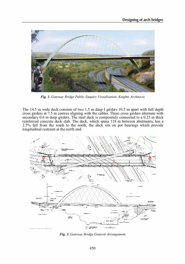
Fig. 1. Gateway Bridge Public Enquiry Visualisation, Knights Architects.
The 14.5 m wide deck consists of two 1.5 m deep I girders 10.5 m apart with full depth cross girders at 7.5 m centres aligning with the cables. These cross girders alternate with secondary 0.6 m deep girders. The steel deck is compositely connected to a 0.25 m thick reinforced concrete deck slab. The deck, which spans 118 m between abutments, has a 2.5% fall from the south to the north, the deck sits on pot bearings which provide longitudinal restraint at the north end.
Fig. 2. Gateway Bridge General Arrangement.
450
Designing of arch bridges

The arch bases and deck abutments are founded on reinforced concrete pad foundations that bear directly on the sandstone/siltstone bed rock. Due to the potential presence of historic coal mine workings in the area the ground is to be treated with drilling and grouting prior to foundation construction. 2. LAYOUT OPTIMISATION 2.1. Structural form 2.1.1. Feature structure requirements As part of the Heads of the Valleys Landscape Strategy document there was a requirement from the Welsh Government, the ultimate Client for the scheme, for a feature structure at the Brymawr Junction. The structures is positioned where the A465 enters the Breacon Beacons National park and there was a desire to have a visually striking “gateway” structure at this location. Realignment of the A465 mainline through the junction due to value engineering activities at the Early Contractor Involvement stages of the project defined the structures location and constraints. 2.1.2. Preliminary Design Optioneering During with the preliminary design optioneering a number of solutions were considered by the design team, with the single skewed arch form selected for a number of reasons. The location of the two hillsides and presence of the River Clydach and geological Site of Special Scientific Interest required the permanent span to be over 100 m, this meant that a two span structure would not have been feasible due to the requirement for a central pier to be located between the A465 and River Clydach / SSSI, with limited options for protection from the carriageway. The steep valley setting is well suited to an arch bridge. An arch under the deck was investigated, however this was not selected as preliminary design work showed that the rise to span required to meet the site constraints were too shallow to be economical with significant bending moments developing within the arch rib. A double arch arrangement running parallel to the deck, using expertise from the Walton Bridge design [1] would have required greater steel quantities due to longer arch spans, and was shown architecturally to have a significant profile from the A465 mainline with the structure crossing at a skew. As the preferred highway alignment required the bridge to cross the valley at a skew the single skewed arch arrangement allows the arch rib to cross perpendicular to the valley and so this arrangement minimises the span and therefore provides a more economical solution with a reduced visual impact. Architectural input was sought on defining the final arch size, shape and position within its environment, as well as structure finishes 2.2. Cable arrangement The detailed design activities included the optimisation of the cable alignment, working around the structural, material and geometric constraints imposed by the skewed arch.
451
8th International Conference on Arch Bridges
October 5-7, 2016, Wrocław, Poland

This work was heavily informed by the development of a 3D model to understand the complex geometry involved with the structural form. 2.2.1. Number of cables The preliminary design considered the use of high tensile bars, however as part of the design development a Full Locked Coil (FLC) cable system was proposed. The FLC system had a much higher yield strength and therefore an increased connection spacing could be used in the detailed design, with a lower connection spacing chosen to allow optimisation of the cross girder spacing for the ladder deck, reducing steelwork quantities and permanent falsework requirements. Additionally, for the forces carried in the cables the FLC system required was in the middle of the manufacturers product range allowing greater flexibility to change size at a the final detailed design stage compared to the high tensile bar. 2.2.2. Cable alignment At the outset of the preliminary design the cables were paired up according to a similar axial force and conservatively positioned as far up the arch rib as possible to avoid the structure free zone, shown in Fig 3, around the carriageway set by TD 27/05 [2]. See Fig. 4 for arrangement. Following risk ranking calculations for the arch rib and cables to the requirements laid down in the NA to BS EN 1991-1-7 [3] a barrier was provided at the back of the verge to protect against impact from an errant vehicle.
Fig. 3. Deck cross section showing Structure Free Zone (SFZ) constraints.
As part of the design development the cable alignment was optimised to a straightened cable alignment with connections spaced evenly around the arch, with a reduced number of cables as per the discussion above in section 2.2.1 to give the final detailed design arrangement as shown in Fig. 5. The initial driver behind the straightened alignment was to achieve simplicity of the connection detail and internal arch steelwork, with a straight load path through the connections to minimise the resultant force transferred into arch.
452
Designing of arch bridges

Skewed arches with unsymmetrical cable spacing around the arch centrelines have previously been shown to have significant out of plane moments develop in the arch rib therefore the design team looked to assess this impact of this effect for the different alignments. Keeping all other variables constant the preliminary design model was updated for the revised alignment and compared to understand the change in structural behaviour, as shown in Fig. 6.
Fig. 4. Cable alignment at preliminary design with varying cable angle at arch.
Fig. 5. Revised cable alignment with common hanger alignment.
In plane bending was significantly reduced for the revised alignment as the cables were spread more evenly around the arch, with less load applied at the crown. However, an increase in out of plane bending was observed due to not pairing cables with similar axial force and also having an increased number of unpaired cables in the arrangement. Axial force in the arch rib remained unchanged, indicating that the cable group had the same stiffness and was picking up the same load in both arrangements, therefore load distribution through the deck back to the abutments should be the same. This was verified by checking the maximum bending moments for longitudinal girder design.
453
8th International Conference on Arch Bridges
October 5-7, 2016, Wrocław, Poland

Fig. 6. Bending along arch rib for varying and straight alignments.
There were a number of geometric constraints imposed by the geometry of the skewed arch, inclined cables and SFZ, therefore the design team utilised the 3D modelling capability available within the department to identify clashes that were not visible from sketches or 2D drawings and optimise the solution. 3. ARCH DESIGN The bridge is designed in accordance with the Eurocodes, UK National Annexes and the associated Design Manual for Roads and Bridges documents. The bridge is designed for EN 1991-2 Load Model 1 and Load Model 3 traffic loading. The heaviest Load Model 3 vehicle designed for is the SV196 defined in the UK National Annex [4]. In accordance with EN 1993-1-11 the bridge is designed to withstand the accidental or maintenance removal of a single cable. 3.1. Global analysis The global analysis of the bridge was carried out using a beam and shell model in LUSAS 15.1. The main steelwork elements were modelled as line beams and the concrete deck slab was modelled using shell elements. Fig. 7 shows the model used.
454
Designing of arch bridges
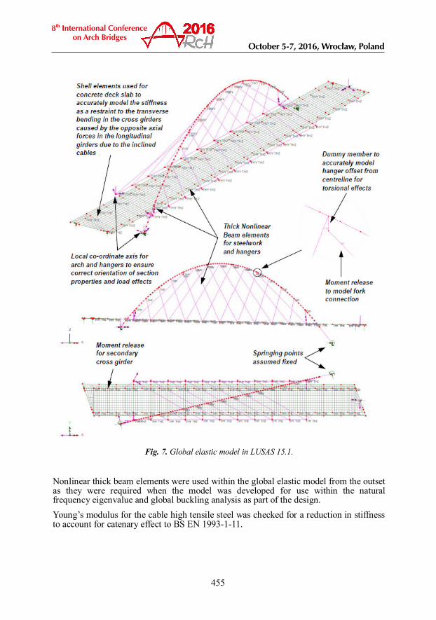
Fig. 7. Global elastic model in LUSAS 15.1.
Nonlinear thick beam elements were used within the global elastic model from the outset as they were required when the model was developed for use within the natural frequency eigenvalue and global buckling analysis as part of the design. Young’s modulus for the cable high tensile steel was checked for a reduction in stiffness to account for catenary effect to BS EN 1993-1-11.
455
8th International Conference on Arch Bridges
October 5-7, 2016, Wrocław, Poland

3.2. Design against buckling The arch rib’s susceptibility to local and global buckling needed to be considered in the design, with longitudinal stiffeners provided within the arch to control the local buckling effects. Local buckling of the stiffened panels and sub panels within the arch rib was determined using EN 1993-1-5. Conservatively a column buckling mode was considered for the stiffened panels, with an imperfection factor and reduction factor for longitudinal stiffeners curved in elevation as per PD6695-2 [5] applied when calculating the buckling reduction factor. In order to provide a more economic section the contribution of the longitudinal stiffeners were taken within the global analysis and section capacity calculations. This was justified by ensuring the stiffeners were detailed as continuous through the arch, with the stiffeners passing through cut outs in the internal diaphragms and lapped as per the requirements of BS 5400-3 [6] where the web stiffeners changed in number. The full cross section was included within the global analysis model as the reduction for buckling was shown to be not less than half the gross area in accordance with BS EN 1993-1-5. For global buckling the LUSAS model was used to determine the elastic critical buckling load from which the reduction for global buckling to EN 1993-1-1 was calculated. Due to the size and stiffness of the arch only a 5% reduction was observed. 3.3. Torsion, distortion and warping The effects of distortion and warping in the arch rib were considered to PD 6695-2 [5], along with guidance from industry publications including; SCI Box Girder [7] and Thomas Telford Eurocode 3-2 design guides [8]. The diaphragm stiffness was calculated using the equations within PD 6695-2 [5] including the use of a ring frame model to determine the effects of the stiffener arrangement on the diaphragm. The effectiveness of the diaphragms to resist the distortion and warping effects was then used to calculate the transverse distortional bending stress and distortional warping stress within the arch ribs. As these stresses were relatively small a simple reduction to the steel yield stress was applied for determining the usage of the section. The diaphragms were then designed to resist the distortion, in addition to the effects of the curvature and the local effects required to transfer the cable forces into the arch rib. Torsion was considered as St Venants torsional shear stress from torque in thin walled sections. This was then combined with the distortional warping shear stress and stress from the effects of the arches curvature in addition to the shear stress within the arch. 4. CONSTRUCTION METHODOLOGY 4.1. Proposed construction sequence The construction method was developed around the constraints imposed by the structures location and the structural form in close conjunction with the contractor and fabricator. The construction sequence is outlined in Fig. 8. The location of the trestles was constrained by the need to avoid the A465 and River Clydach / Clydach Gorge SSSI and to make use of the existing level ground at the cycle path. Due to these constraints the trestles are skewed relative to the deck.
456
Designing of arch bridges

1 Deck steelwork is erected on temporary trestles to form a 4 span structure.
2 Precast reinforced concrete deck panels for the deck cantilevers are installed.
3 The main deck slab cast in-situ to provide restraint against the cables skewed loading
4 Three temporary trestles to support the arch are erected on the deck.
5 The arch is lifted into place in 4 sections using cranes located behind abutments.
6 The arch base is fixed against rotations and the arch temporary trestles are removed.
7 The cables are installed to correct length
8 The deck trestles are removed transferring the deck load to the cables.
Fig. 8. Gateway bridge construction sequence.
The effects of this construction sequence were taken into account in the design by creating a separate LUSAS model for each construction stage and building up the stresses in the steelwork due to the permanent loads from these models. These construction stage models were then used to derive loading on the temporary works for design of the temporary trestles and foundations.
457
8th International Conference on Arch Bridges
October 5-7, 2016, Wrocław, Poland

4.2. Achieving design cable forces During the detailed design the target cable forces were determined by applying permanent loading to the final model of the bridge with the trestles removed and the cables in place as shown in Fig. 9a. which assumes the hangers are installed so that they are loaded immediately. The cables are to be installed with no pretension whilst the deck trestles are in place and the trestles then released to load the cables. Using this method will not load the cables as per the target design values determined from the final model, Fig. 9b illustrates how the deck loading is applied to the cables in the actual construction sequence resulting in different hanger forces to the load application in Fig. 9a.
Fig. 9. a) Deck self-weight applied in final model of bridge used to determine target hanger
forces; b) deck self-weight as applied in actual construction sequence model.
The graph in Fig. 10 shows the bending moment in one of the deck main beams resulting from the two scenarios, with bending moment from the final model lower in the midspan section of the bridge, allowing a more efficient design to be achieved.
Fig. 10. Bending moment in main deck beam from loading as in Fig. 9.
a) b)
458
Designing of arch bridges

It was initially proposed that the cables should be re-tensioned on site after the trestles have been removed in order to achieve these desired final cable forces. However, the best option was for the cables to be installed with some additional slack, rather than the actual distance between then anchorages whilst the deck is still on the trestles. Then when the trestles are removed then the cables that are slightly over-length, i.e. with some slack, will pick up less force than the cables which are shorter and so are loaded first. By specifying how much slack each cable should have the target design cable force should be achieved when the trestles are removed. To determine the required slack for each cable a nonlinear analysis was carried out with the LUSAS model. The slack of each hanger was included in the model by modifying the stress-strain curve in the material properties for each hanger, with strain at which the cable started to pick up load adjusted as shown in Fig. 11.
Fig. 11. Material property adjustment to model slack.
The reactions in the trestles supporting in the deck were applied as downward forces in the model to represent the trestle removals as in Fig 9b, with the load incremented gradually to determine the correct hanger force. The effect of the trestles removal order was investigated and it was established that this did not alter the final hanger forces. The required slack for each hanger was first estimated using the difference between two linear models loaded as in Fig 9a and Fig 9b. An iterative process was then followed adjusting the slacks and rerunning the nonlinear model until the hanger forces determined from the nonlinear model matched the target design values from the linear model with the deck load applied as a uniformly distributed load. 5. ACKNOWLEDGEMENTS This paper is published with the permission of the Welsh Government and Costain. The authors would also like to acknowledge the contribution from the fabricator Victor Buyck Steel Construction and Knights Architects. REFERENCES [1] HENDY CR, SMITH DA, WHEATLEY RN,. Walton Bridge – A new arch bridge
over the River Thames, Arch 2013, 2-4th October 2013, Croatia
459
8th International Conference on Arch Bridges
October 5-7, 2016, Wrocław, Poland

[2] THE HIGHWAYS AGENCY. TD27/05, Cross Sections and Headrooms, The
Design Manual for Roads and Bridges (DMRB) Volume 6, Section 1, Part 2. 2005 [3] BSI. NA to BS EN 1991-1-7 Actions on Structures – Part 1-7: Accidental Actions,
London, UK, 2006 [4] BSI. NA to BS EN 1991-2 Actions on Structures – Part 2: Traffic Loads on
Bridges, London, UK, 2008 [5] BSI. PD 6695-2. Recommendations for the Design of Bridges to BS EN 1993,
London, UK, 2012 [6] BSI. BS8500-3. Code of Practice for Design of Steel Bridges. BSI, London, UK,
2000 [7] ILES, D.C. Design guide for composite box girder bridges. (P140). SCI, 2004 [8] HENDY, C. R. & MURPHY, C. J. Designers' Guide to EN 1993-2 Eurocode 3:
Design of steel structures. Part 2: Steel bridges. Thomas Telford Ltd, 2007
460
Designing of arch bridges