Design of the Electrical Drive for the High-Pressure GDI ... · Design of the Electrical Drive for...
14
Design of the Electrical Drive for the High-Pressure GDI Injector in a 500cc Motorbike Engine Wen-Chang Tsai, Peng-Cheng Yu International Journal of Engineering and Industries, volume 2, Number 1, March, 2011 Design of the Electrical Drive for the High-Pressure GDI Injector in a 500cc Motorbike Engine Wen-Chang Tsai 1&2 , Peng-Cheng Yu 2 1 Advanced Engine Research Center, 2 Department of Electrical Engineering, Kao Yuan University Luju 82141, Kaohsiung County, Taiwan [email protected] doi:10.4156/ ijei.vol2. issue1.9 Abstract In order to meet future emission regulations, improve the power and reduce fuel consumption of an engine, a high-pressure GDI injector is gradually replacing the conventional port fuel injector as it is able to provide fuel injection with a more effective fuel spray atomization and tip penetration. Engine performance can therefore, be improved by using such a high-pressure swirl injector. In order to fully utilize the advantages of the GDI injector, the electric driving circuit is required to be designed with a faster response and finer precision control. In this paper, a programmable injector driving circuit for various high-pressure GDI injectors is designed and presented. A Comparison between two driving strategies of GDI injectors is summarized. Experimental tests for the designed electric driving circuit are investigated to verify its feasibility. The test of the electric driving circuit for the injection quantity of the GDI injector is under the conditions of 10 MPa fuel pressures, 1200-2000μs injection pulse duration and DC 70V executing power voltage. The GDI injector coils are driven under three pulse width (12/5/3A) peak and holding current waveforms to generate the electromagnetic force to draw back and hold the nozzle needle of the injector. Also, PWM control is introduced to the 3A holding current during the last pulse duration for quickening the cut-off response time of the GDI injector. Results show that this electric driving circuit is capable of operating stably and assures the accurate injection quantity of the gasoline direct injector. Keywords: Electrical Driving Circuit, Electronic Control Unit (ECU), Gasoline Direct Injector (GDI), Motorbike Engine 1. Introduction A four-stroke GDI motorbike engine is mainly designed to achieve fuel economy and to meet the requirements of stringent emission regulations and superior driving performance. Control strategies for mixture-preparation and combustion of GDI engines have been proposed and developed in the past decade [1-4] however, most of the researches focuses on automotive engines and little information are available for the spark ignition engines with small displacement. Also, an advanced electrical driving circuit allows a more sophisticated control over electronic diesel injection system by the emerging application of power electronics [5-6]. The motorbike engines will meet the new emission regulations in the near future. In-cylinder direct injection technology is a good choice due to its advantages in potential fuel economy and emission reduction. A testing study was carried out on KYMCO Xciting-500 motorbike engine with certain modifications in its cylinder head. The specifications of the base engine with the PFI injection are shown in Table 1. In this paper, a programmable injector driving circuit is presented. Comparison between two driving strategies of GDI injectors is summarized. Three pulse width (12/5/3A) peak and holding current waveforms from the designed injector driving circuit are supplied to the injector coils to generate the electromagnetic force to draw back and hold the nozzle needle of an injector. Also, the 3A holding current during the last pulse duration is controlled by PWM to speed up the cut-off time of the GDI injector. This electric driving circuit is verified under 10 Mpa fuel pressures, 1200-2000μs injection pulse duration and DC 70V executing power voltages. Moreover, requests for optimizing injection parameters are put forward. Limited by the structure of the cylinder head, the fuel injector is center-mounted at an included angle of 12 0 to the vertical plane between the intake and exhaust valves. - 70 -
Transcript of Design of the Electrical Drive for the High-Pressure GDI ... · Design of the Electrical Drive for...
Design of the Electrical Drive for the High-Pressure GDI Injector in a 500cc Motorbike Engine Wen-Chang Tsai, Peng-Cheng Yu
International Journal of Engineering and Industries, volume 2, Number 1, March, 2011
Design of the Electrical Drive for the High-Pressure GDI Injector in a 500cc Motorbike Engine
Wen-Chang Tsai1&2, Peng-Cheng Yu2
1Advanced Engine Research Center, 2Department of Electrical Engineering, Kao Yuan University
Luju 82141, Kaohsiung County, Taiwan [email protected]
doi:10.4156/ ijei.vol2. issue1.9
Abstract In order to meet future emission regulations, improve the power and reduce fuel consumption of an
engine, a high-pressure GDI injector is gradually replacing the conventional port fuel injector as it is able to provide fuel injection with a more effective fuel spray atomization and tip penetration. Engine performance can therefore, be improved by using such a high-pressure swirl injector. In order to fully utilize the advantages of the GDI injector, the electric driving circuit is required to be designed with a faster response and finer precision control. In this paper, a programmable injector driving circuit for various high-pressure GDI injectors is designed and presented. A Comparison between two driving strategies of GDI injectors is summarized. Experimental tests for the designed electric driving circuit are investigated to verify its feasibility. The test of the electric driving circuit for the injection quantity of the GDI injector is under the conditions of 10 MPa fuel pressures, 1200-2000μs injection pulse duration and DC 70V executing power voltage. The GDI injector coils are driven under three pulse width (12/5/3A) peak and holding current waveforms to generate the electromagnetic force to draw back and hold the nozzle needle of the injector. Also, PWM control is introduced to the 3A holding current during the last pulse duration for quickening the cut-off response time of the GDI injector. Results show that this electric driving circuit is capable of operating stably and assures the accurate injection quantity of the gasoline direct injector.
Keywords: Electrical Driving Circuit, Electronic Control Unit (ECU),
Gasoline Direct Injector (GDI), Motorbike Engine
1. Introduction A four-stroke GDI motorbike engine is mainly designed to achieve fuel economy and to meet the
requirements of stringent emission regulations and superior driving performance. Control strategies for mixture-preparation and combustion of GDI engines have been proposed and developed in the past decade [1-4] however, most of the researches focuses on automotive engines and little information are available for the spark ignition engines with small displacement. Also, an advanced electrical driving circuit allows a more sophisticated control over electronic diesel injection system by the emerging application of power electronics [5-6]. The motorbike engines will meet the new emission regulations in the near future. In-cylinder direct injection technology is a good choice due to its advantages in potential fuel economy and emission reduction. A testing study was carried out on KYMCO Xciting-500 motorbike engine with certain modifications in its cylinder head. The specifications of the base engine with the PFI injection are shown in Table 1.
In this paper, a programmable injector driving circuit is presented. Comparison between two driving strategies of GDI injectors is summarized. Three pulse width (12/5/3A) peak and holding current waveforms from the designed injector driving circuit are supplied to the injector coils to generate the electromagnetic force to draw back and hold the nozzle needle of an injector. Also, the 3A holding current during the last pulse duration is controlled by PWM to speed up the cut-off time of the GDI injector. This electric driving circuit is verified under 10 Mpa fuel pressures, 1200-2000μs injection pulse duration and DC 70V executing power voltages. Moreover, requests for optimizing injection parameters are put forward. Limited by the structure of the cylinder head, the fuel injector is center-mounted at an included angle of 120 to the vertical plane between the intake and exhaust valves.
- 70 -
Design of the Electrical Drive for the High-Pressure GDI Injector in a 500cc Motorbike Engine Wen-Chang Tsai, Peng-Cheng Yu
International Journal of Engineering and Industries, volume 2, Number 1, March, 2011
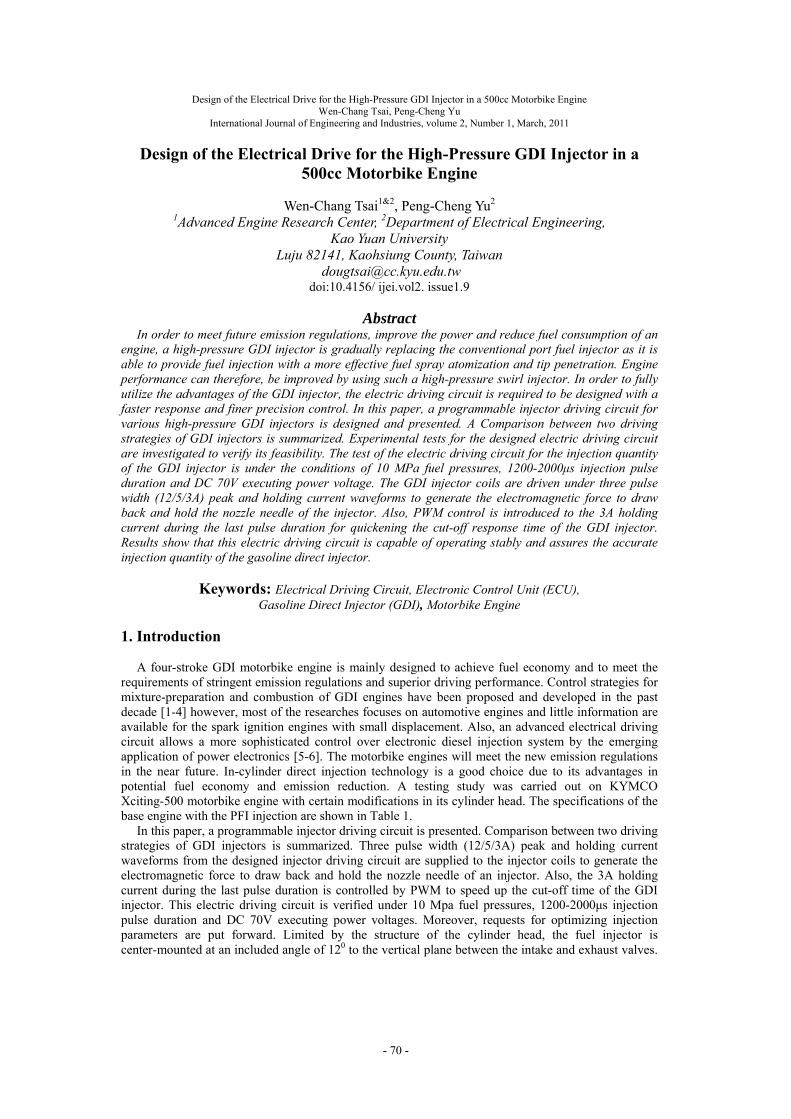
The spark plug is positioned near the center. Fig.1 shows a schematic picture of this configuration.
(a) (b) Figure 1. (a) Cylinder head of a PFI engine, (b) Cylinder head of a GDI engine
Table 1. Basic engine specification
Xciting-500cc
Engine type single cylinder, four strokes, water cooling
Displacement 498.5CC
Bore× Stroke Φ92×75
Compression ratio 10.5
Maximun power 38/7500( hp/rpm )
Maximun torque 4.1/5500( kg-m/rpm)
Ignition method Crystal
Spark plug NGK CR7E
2. GDI Fuel System
The fuel injection system mainly comprises of four parts: the fuel supply system, electronic control
unit (ECU), electrical driving circuit and an injector, as shown in Fig. 2. The fuel supply system provides a constant 6-10 Mpa pressure resource for the injector. The injection quantity and timing of the injector are controlled by using an electronic control unit (ECU), which computes and analyzes the analogue and digital input signals from various engine sensors. A Bosch GDI single-hole injector is installed and tested on the cylinder head of a 500cc motorbike engine.
2.1. Fuel Supply System
The fuel supply system is similar to the conventional design of GDI engines in high pressure fuel
containers. This paper adopts a Bosch GDI single-hole injector as shown in Fig. 2(a). Its pressure can be operated between 6 and 10 MPa (max) which has been commonly used in some GDI engines. In the fuel supply system illustrated in Fig. 2(b), the high pressure Nitrogen bottle pulls the operating pressure of the stainless fuel cylinder up to 6-10 Mpa (max). It is expected to maintain this constant value to avoid any disturbances to the GDI injector performance caused by the gasoline pump pressure dip at high operating speed of motorbike engines. The pressure in the cylinder is maintained at a constant value through regulating high pressure Nitrogen flow. The pressure fluctuation of the fuel container, caused by closing and opening of the nozzle is about 0.5 MPa.
A programmable injector driving circuit is designed to control the opening, injecting and closing
Locations of the injector nozzle and spark plug
GDI nozzle
- 71 -
Design of the Electrical Drive for the High-Pressure GDI Injector in a 500cc Motorbike Engine Wen-Chang Tsai, Peng-Cheng Yu
International Journal of Engineering and Industries, volume 2, Number 1, March, 2011
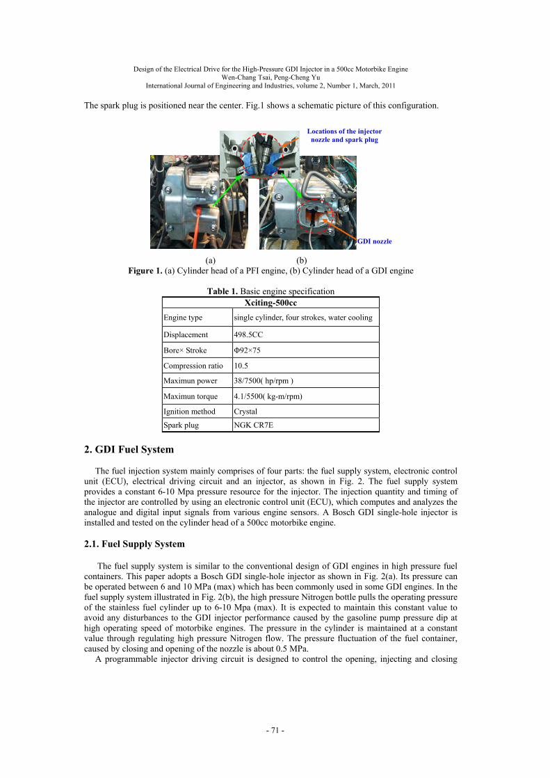
time of the GDI nozzle. According to the test requirements, the parameters of the fuel injection system are calibrated properly to each part. The fuel pressure in the GDI Bosch injector mounted on a 500cc motorbike engine cylinder head is set at 10 MPa in the test as shown in Fig.2(c).
(a) (b) (c) Fig 2. (a) The Bosch GDI single-hole injector test device, (b) High pressure 6~10 Mpa (Max) fuel
supply system, (c) The test system of a Bosch GDI single-hole injector mounted on a 500cc motorbike engine cylinder head
2.2. Injector
Usually, an inward opening swirl injector is preferred for engines with small displacement in
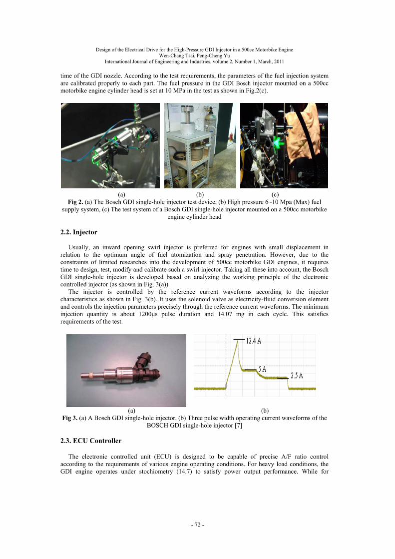
relation to the optimum angle of fuel atomization and spray penetration. However, due to the constraints of limited researches into the development of 500cc motorbike GDI engines, it requires time to design, test, modify and calibrate such a swirl injector. Taking all these into account, the Bosch GDI single-hole injector is developed based on analyzing the working principle of the electronic controlled injector (as shown in Fig. 3(a)).
The injector is controlled by the reference current waveforms according to the injector characteristics as shown in Fig. 3(b). It uses the solenoid valve as electricity-fluid conversion element and controls the injection parameters precisely through the reference current waveforms. The minimum injection quantity is about 1200μs pulse duration and 14.07 mg in each cycle. This satisfies requirements of the test.
(a) (b) Fig 3. (a) A Bosch GDI single-hole injector, (b) Three pulse width operating current waveforms of the
BOSCH GDI single-hole injector [7]
2.3. ECU Controller The electronic controlled unit (ECU) is designed to be capable of precise A/F ratio control
according to the requirements of various engine operating conditions. For heavy load conditions, the GDI engine operates under stochiometry (14.7) to satisfy power output performance. While for
- 72 -
Design of the Electrical Drive for the High-Pressure GDI Injector in a 500cc Motorbike Engine Wen-Chang Tsai, Peng-Cheng Yu
International Journal of Engineering and Industries, volume 2, Number 1, March, 2011
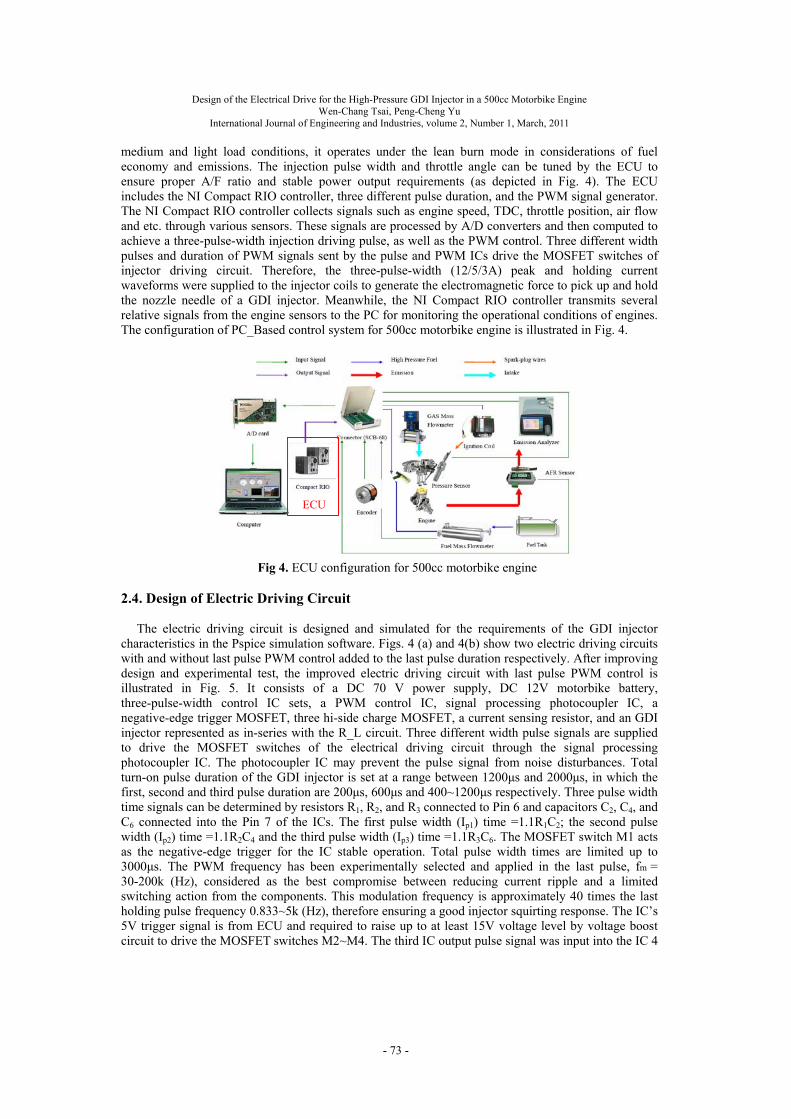
medium and light load conditions, it operates under the lean burn mode in considerations of fuel economy and emissions. The injection pulse width and throttle angle can be tuned by the ECU to ensure proper A/F ratio and stable power output requirements (as depicted in Fig. 4). The ECU includes the NI Compact RIO controller, three different pulse duration, and the PWM signal generator. The NI Compact RIO controller collects signals such as engine speed, TDC, throttle position, air flow and etc. through various sensors. These signals are processed by A/D converters and then computed to achieve a three-pulse-width injection driving pulse, as well as the PWM control. Three different width pulses and duration of PWM signals sent by the pulse and PWM ICs drive the MOSFET switches of injector driving circuit. Therefore, the three-pulse-width (12/5/3A) peak and holding current waveforms were supplied to the injector coils to generate the electromagnetic force to pick up and hold the nozzle needle of a GDI injector. Meanwhile, the NI Compact RIO controller transmits several relative signals from the engine sensors to the PC for monitoring the operational conditions of engines. The configuration of PC_Based control system for 500cc motorbike engine is illustrated in Fig. 4.
Fig 4. ECU configuration for 500cc motorbike engine
2.4. Design of Electric Driving Circuit The electric driving circuit is designed and simulated for the requirements of the GDI injector
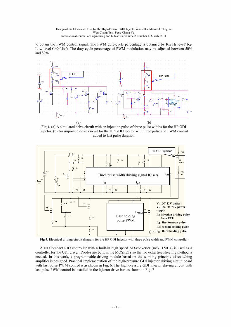
characteristics in the Pspice simulation software. Figs. 4 (a) and 4(b) show two electric driving circuits with and without last pulse PWM control added to the last pulse duration respectively. After improving design and experimental test, the improved electric driving circuit with last pulse PWM control is illustrated in Fig. 5. It consists of a DC 70 V power supply, DC 12V motorbike battery, three-pulse-width control IC sets, a PWM control IC, signal processing photocoupler IC, a negative-edge trigger MOSFET, three hi-side charge MOSFET, a current sensing resistor, and an GDI injector represented as in-series with the R_L circuit. Three different width pulse signals are supplied to drive the MOSFET switches of the electrical driving circuit through the signal processing photocoupler IC. The photocoupler IC may prevent the pulse signal from noise disturbances. Total turn-on pulse duration of the GDI injector is set at a range between 1200μs and 2000μs, in which the first, second and third pulse duration are 200μs, 600μs and 400~1200μs respectively. Three pulse width time signals can be determined by resistors R1, R2, and R3 connected to Pin 6 and capacitors C2, C4, and C6 connected into the Pin 7 of the ICs. The first pulse width (Ip1) time =1.1R1C2; the second pulse width (Ip2) time =1.1R2C4 and the third pulse width (Ip3) time =1.1R3C6. The MOSFET switch M1 acts as the negative-edge trigger for the IC stable operation. Total pulse width times are limited up to 3000μs. The PWM frequency has been experimentally selected and applied in the last pulse, fm = 30-200k (Hz), considered as the best compromise between reducing current ripple and a limited switching action from the components. This modulation frequency is approximately 40 times the last holding pulse frequency 0.833~5k (Hz), therefore ensuring a good injector squirting response. The IC’s 5V trigger signal is from ECU and required to raise up to at least 15V voltage level by voltage boost circuit to drive the MOSFET switches M2~M4. The third IC output pulse signal was input into the IC 4
ECU
- 73 -
Design of the Electrical Drive for the High-Pressure GDI Injector in a 500cc Motorbike Engine Wen-Chang Tsai, Peng-Cheng Yu
International Journal of Engineering and Industries, volume 2, Number 1, March, 2011
to obtain the PWM control signal. The PWM duty-cycle percentage is obtained by R39 Hi level/ R40 Low level C=0.01uf). The duty-cycle percentage of PWM modulation may be adjusted between 50% and 80%.
(a) (b) Fig 4. (a) A simulated drive circuit with an injection pulse of three pulse widths for the HP GDI
Injector, (b) An improved drive circuit for the HP GDI Injector with three pulse and PWM control added to last pulse duration
Fig 5. Electrical driving circuit diagram for the HP GDI Injector with three pulse width and PWM controller A NI Compact RIO controller with a built-in high speed AD-converter (max. 1MHz) is used as a
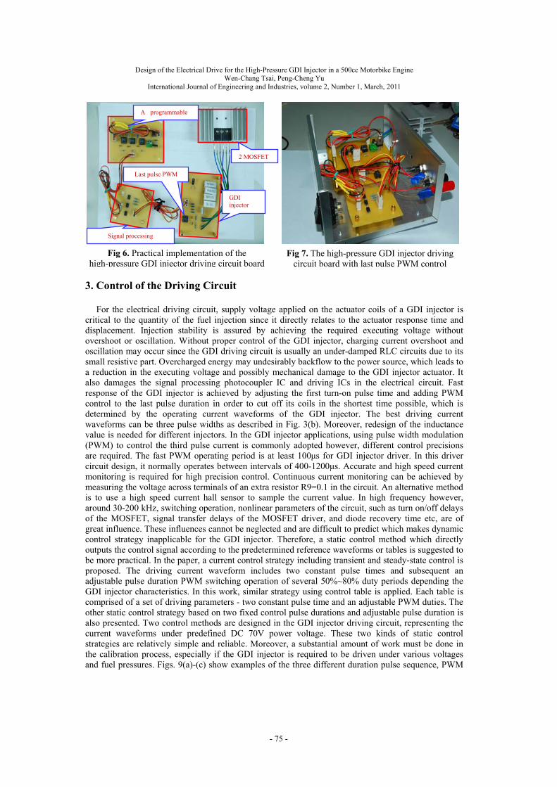
controller for the GDI driver. Diodes are built in the MOSFETs so that no extra freewheeling method is needed. In this work, a programmable driving module based on the working principle of switching amplifier is designed. Practical implementation of the high-pressure GDI injector driving circuit board with last pulse PWM control is as shown in Fig. 6. The high-pressure GDI injector driving circuit with last pulse PWM control is installed in the injector drive box as shown in Fig. 7
HP GDI HP GDI
HP GDI Injector
V2: DC 12V battery V3: DC 60~70V power supply
Ip: injection driving pulse from ECU
Ip1: first turn-on pulse
Ip2: second holding pulse
Ip3: third holding pulse
Three pulse width driving signal IC sets
Last holding pulse PWM
Ip3
Ip2Ip1
IPWM
Ip
- 74 -
Design of the Electrical Drive for the High-Pressure GDI Injector in a 500cc Motorbike Engine Wen-Chang Tsai, Peng-Cheng Yu
International Journal of Engineering and Industries, volume 2, Number 1, March, 2011
3. Control of the Driving Circuit
For the electrical driving circuit, supply voltage applied on the actuator coils of a GDI injector is
critical to the quantity of the fuel injection since it directly relates to the actuator response time and displacement. Injection stability is assured by achieving the required executing voltage without overshoot or oscillation. Without proper control of the GDI injector, charging current overshoot and oscillation may occur since the GDI driving circuit is usually an under-damped RLC circuits due to its small resistive part. Overcharged energy may undesirably backflow to the power source, which leads to a reduction in the executing voltage and possibly mechanical damage to the GDI injector actuator. It also damages the signal processing photocoupler IC and driving ICs in the electrical circuit. Fast response of the GDI injector is achieved by adjusting the first turn-on pulse time and adding PWM control to the last pulse duration in order to cut off its coils in the shortest time possible, which is determined by the operating current waveforms of the GDI injector. The best driving current waveforms can be three pulse widths as described in Fig. 3(b). Moreover, redesign of the inductance value is needed for different injectors. In the GDI injector applications, using pulse width modulation (PWM) to control the third pulse current is commonly adopted however, different control precisions are required. The fast PWM operating period is at least 100μs for GDI injector driver. In this driver circuit design, it normally operates between intervals of 400-1200μs. Accurate and high speed current monitoring is required for high precision control. Continuous current monitoring can be achieved by measuring the voltage across terminals of an extra resistor R9=0.1 in the circuit. An alternative method is to use a high speed current hall sensor to sample the current value. In high frequency however, around 30-200 kHz, switching operation, nonlinear parameters of the circuit, such as turn on/off delays of the MOSFET, signal transfer delays of the MOSFET driver, and diode recovery time etc, are of great influence. These influences cannot be neglected and are difficult to predict which makes dynamic control strategy inapplicable for the GDI injector. Therefore, a static control method which directly outputs the control signal according to the predetermined reference waveforms or tables is suggested to be more practical. In the paper, a current control strategy including transient and steady-state control is proposed. The driving current waveform includes two constant pulse times and subsequent an adjustable pulse duration PWM switching operation of several 50%~80% duty periods depending the GDI injector characteristics. In this work, similar strategy using control table is applied. Each table is comprised of a set of driving parameters - two constant pulse time and an adjustable PWM duties. The other static control strategy based on two fixed control pulse durations and adjustable pulse duration is also presented. Two control methods are designed in the GDI injector driving circuit, representing the current waveforms under predefined DC 70V power voltage. These two kinds of static control strategies are relatively simple and reliable. Moreover, a substantial amount of work must be done in the calibration process, especially if the GDI injector is required to be driven under various voltages and fuel pressures. Figs. 9(a)-(c) show examples of the three different duration pulse sequence, PWM
GDI injector
A programmable
2 MOSFET
Signal processing
Fig 6. Practical implementation of the high-pressure GDI injector driving circuit board
Last pulse PWM
Fig 7. The high-pressure GDI injector driving circuit board with last pulse PWM control
- 75 -
Design of the Electrical Drive for the High-Pressure GDI Injector in a 500cc Motorbike Engine Wen-Chang Tsai, Peng-Cheng Yu
International Journal of Engineering and Industries, volume 2, Number 1, March, 2011
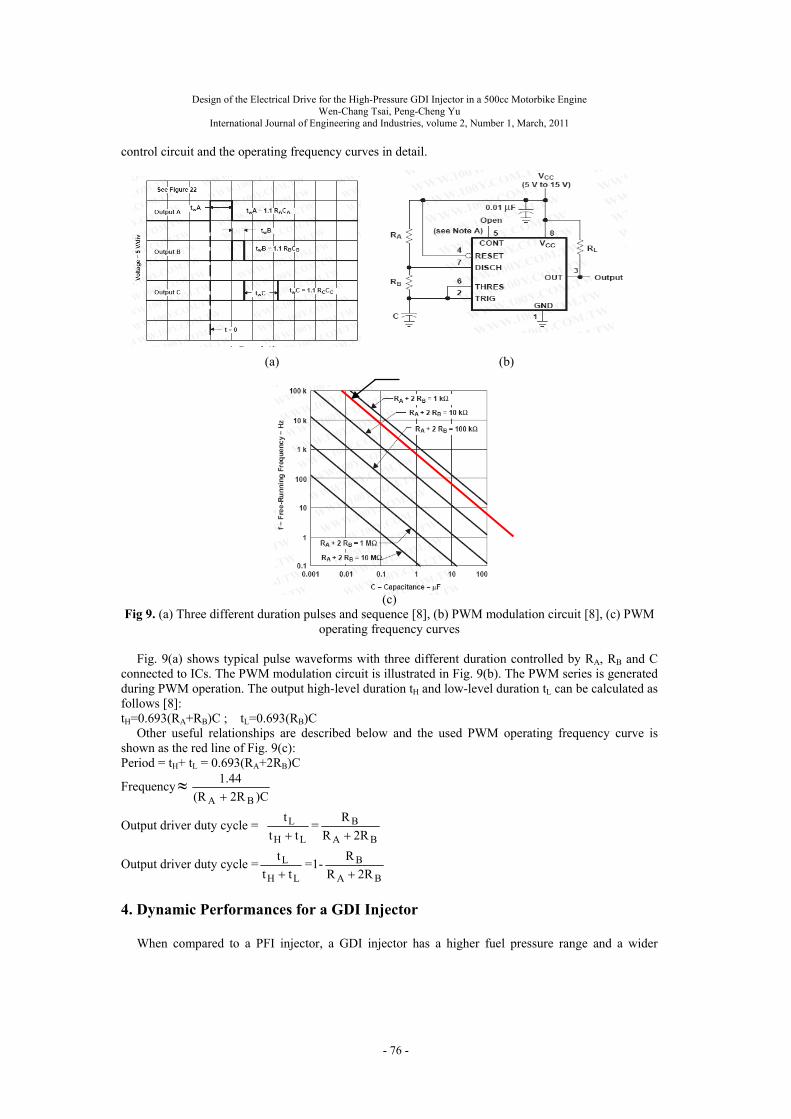
control circuit and the operating frequency curves in detail.
(a) (b)
(c) Fig 9. (a) Three different duration pulses and sequence [8], (b) PWM modulation circuit [8], (c) PWM
operating frequency curves Fig. 9(a) shows typical pulse waveforms with three different duration controlled by RA, RB and C
connected to ICs. The PWM modulation circuit is illustrated in Fig. 9(b). The PWM series is generated during PWM operation. The output high-level duration tH and low-level duration tL can be calculated as follows [8]: tH=0.693(RA+RB)C ; tL=0.693(RB)C
Other useful relationships are described below and the used PWM operating frequency curve is shown as the red line of Fig. 9(c): Period = tH+ tL = 0.693(RA+2RB)C
Frequency)C2R(R
44.1
BA
Output driver duty cycle = LH
L
tt
t
=
BA
B
2RR
R
Output driver duty cycle =LH
L
tt
t
=1-
BA
B
2RR
R
4. Dynamic Performances for a GDI Injector
When compared to a PFI injector, a GDI injector has a higher fuel pressure range and a wider
- 76 -
Design of the Electrical Drive for the High-Pressure GDI Injector in a 500cc Motorbike Engine Wen-Chang Tsai, Peng-Cheng Yu
International Journal of Engineering and Industries, volume 2, Number 1, March, 2011
dynamic flow range. Generally, fuel flow volumes can be controlled by adjusting the driving pulse time. In order to understand the dynamic performance of a GDI injector, the interrelationships among the driving pulse time, the opening and closing time of the GDI injector and its fuel injection quantity must be investigated. These interrelationships can be somewhat complex, involving total driving pulse time, first turn-on pulse time of the injector, and PWM control added to last pulse operation to cut off the injector. The initial input command to the GDI fuel system occurs with the start of fuel injection pulse, which is normally a standard TTL Square-Wave pulse. The required injection pulse time is computed by the ECU according to the requirements of A/F ratio control for various engine operating conditions. The injection pulse signal from ECU is fed into the electrical driving circuit to generate a three-pulse-width (12/5/3A) current waveform. Three different pulse-width current waveforms may be supplied to the solenoid valve in the injector. The executing voltage supplied by the driver may vary from 60 volts to more than 70 volts depending on the GDI injector characteristics. In the research, a MOSFET-switch GDI driver is designed with a wide range of injection pulse durations (maximum 3000μs). The number, shape and length of the single injection pulse and the time between them are the parameters which give control to the combustion process over duration of the complete combustion cycle. The labview software is used for the selection of injection angle and pulse times per cycle, for good A/F ratio controls and for monitoring tasks. The electrical driving circuit for the GDI injector actuators is controlled directly by predetermined engine control algorithms operating in the NI Compact RIO controller. These algorithms may be modified for various GDI injector drivers depending on various engine operating requirements which include the switching of the MOSFETs during the charging and discharging procedure, the current waveform control as well as the last pulse PWM control. The designed GDI injector driver allows rapid control and sophisticated control strategies to achieve superior dynamic performances of a GDI injector.
5. Results and Discussions
The electrical driving circuit models have been simulated in the Pspice environment. Simulations
for two test cases with three different settings of the first pulse duration have been conducted in order to design and validate the GDI injector driver. In one of the test cases, no PWM charging and discharging operations are applied to the last holding pulse; while for the other case, PWM charging and discharging operations are added to the last injection holding pulse. This type of GDI injector requires a maximum charge of 60V-70V with three-pulse-duration rated current waveforms of 12/5/3A. In order to evaluate the operating stability of the GDI injector application, we normally define the injection pulse duration between 1200~2000μs. The experimental results are also reported in this section and compared with the simulation model outputs. In the experiments, an electrical driving circuit is used to drive the GDI injector actuator coils. The components of the electrical driving circuit are capable of withstanding the peak values of current and voltage. The input signal of the electrical driving circuit is a Square-Wave with a 5V amplitude, and the output voltage, whose amplitude is 60-70V, is supplied the GDI injector actuator. The performance of the GDI injector actuator is observed by measuring the current waveforms, opening and closing times, and injection quantities of the GDI injector actuator. The simulation results are shown in Figs. 10-12, which indicates the availability of the GDI injector actuator. Experimental validation has been taken based on GDI injectors. The injector driving module is connected to a GDI engine control unit (ECU).
5.1. Simulation results for high pressure GDI injector
Working performance of the GDI injector is studied in Pspice simulation program based on different
parameter groups. The total driving pulse time is 1500μs and first turn-on driving pulses in the experiment are 120μs, 180μs and 400μs respectively. In order to understand the effects of the last holding pulse PWM control on the injection quantity and the cut-off time, the PWM parameters are added to the simulations. The simulated electrical driving circuit diagrams are shown in Figs. 4 and 5, in which it can be obtained by PWM control of the solenoid to decrease the pressure drop rate in order to obtain a more precise fuel flow volume. The results of the two driving methods for GDI injectors are compared in the simulations. One driving method is by using three injection driving pulse signals with
- 77 -
Design of the Electrical Drive for the High-Pressure GDI Injector in a 500cc Motorbike Engine Wen-Chang Tsai, Peng-Cheng Yu
International Journal of Engineering and Industries, volume 2, Number 1, March, 2011
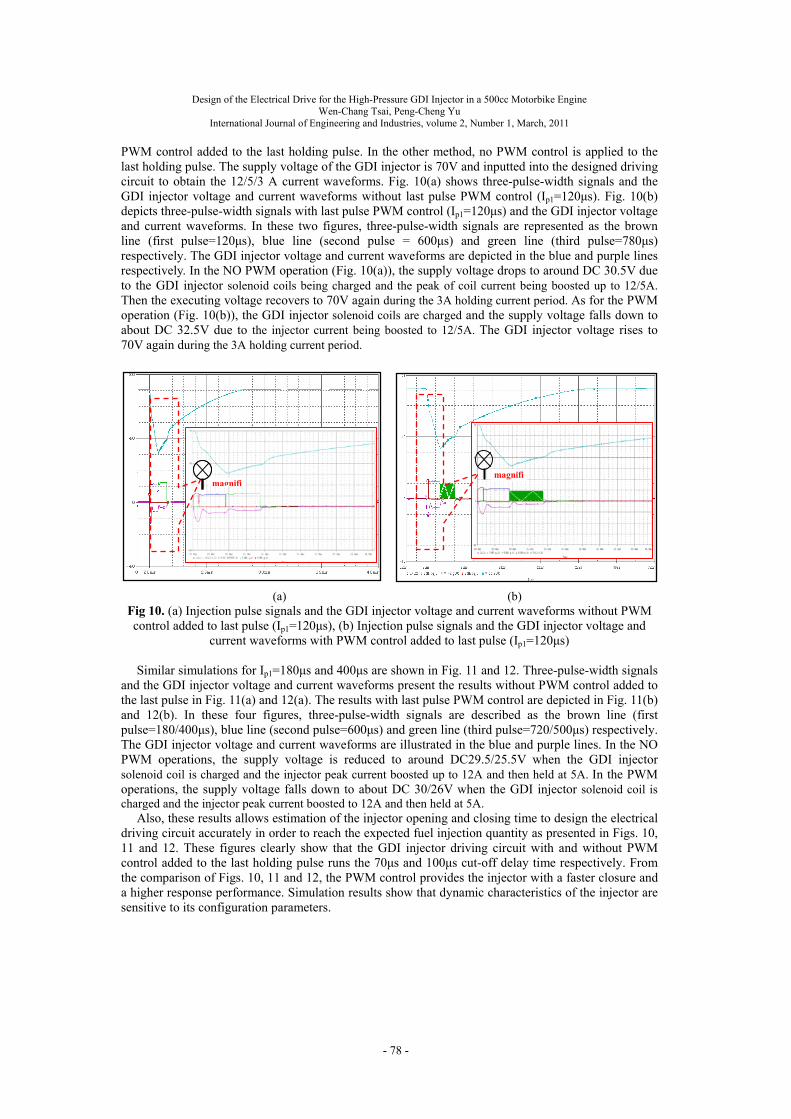
PWM control added to the last holding pulse. In the other method, no PWM control is applied to the last holding pulse. The supply voltage of the GDI injector is 70V and inputted into the designed driving circuit to obtain the 12/5/3 A current waveforms. Fig. 10(a) shows three-pulse-width signals and the GDI injector voltage and current waveforms without last pulse PWM control (Ip1=120μs). Fig. 10(b) depicts three-pulse-width signals with last pulse PWM control (Ip1=120μs) and the GDI injector voltage and current waveforms. In these two figures, three-pulse-width signals are represented as the brown line (first pulse=120μs), blue line (second pulse = 600μs) and green line (third pulse=780μs) respectively. The GDI injector voltage and current waveforms are depicted in the blue and purple lines respectively. In the NO PWM operation (Fig. 10(a)), the supply voltage drops to around DC 30.5V due to the GDI injector solenoid coils being charged and the peak of coil current being boosted up to 12/5A. Then the executing voltage recovers to 70V again during the 3A holding current period. As for the PWM operation (Fig. 10(b)), the GDI injector solenoid coils are charged and the supply voltage falls down to about DC 32.5V due to the injector current being boosted to 12/5A. The GDI injector voltage rises to 70V again during the 3A holding current period.
(a) (b) Fig 10. (a) Injection pulse signals and the GDI injector voltage and current waveforms without PWM control added to last pulse (Ip1=120μs), (b) Injection pulse signals and the GDI injector voltage and
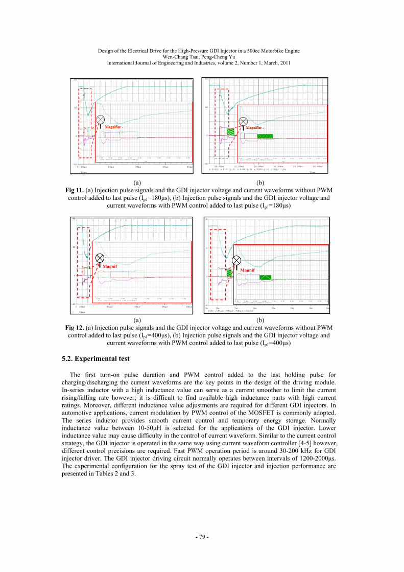
current waveforms with PWM control added to last pulse (Ip1=120μs) Similar simulations for Ip1=180μs and 400μs are shown in Fig. 11 and 12. Three-pulse-width signals
and the GDI injector voltage and current waveforms present the results without PWM control added to the last pulse in Fig. 11(a) and 12(a). The results with last pulse PWM control are depicted in Fig. 11(b) and 12(b). In these four figures, three-pulse-width signals are described as the brown line (first pulse=180/400μs), blue line (second pulse=600μs) and green line (third pulse=720/500μs) respectively. The GDI injector voltage and current waveforms are illustrated in the blue and purple lines. In the NO PWM operations, the supply voltage is reduced to around DC29.5/25.5V when the GDI injector solenoid coil is charged and the injector peak current boosted up to 12A and then held at 5A. In the PWM operations, the supply voltage falls down to about DC 30/26V when the GDI injector solenoid coil is charged and the injector peak current boosted to 12A and then held at 5A.
Also, these results allows estimation of the injector opening and closing time to design the electrical driving circuit accurately in order to reach the expected fuel injection quantity as presented in Figs. 10, 11 and 12. These figures clearly show that the GDI injector driving circuit with and without PWM control added to the last holding pulse runs the 70μs and 100μs cut-off delay time respectively. From the comparison of Figs. 10, 11 and 12, the PWM control provides the injector with a faster closure and a higher response performance. Simulation results show that dynamic characteristics of the injector are sensitive to its configuration parameters.
magnifi
magnifi
- 78 -
Design of the Electrical Drive for the High-Pressure GDI Injector in a 500cc Motorbike Engine Wen-Chang Tsai, Peng-Cheng Yu
International Journal of Engineering and Industries, volume 2, Number 1, March, 2011
(a) (b)
Fig 11. (a) Injection pulse signals and the GDI injector voltage and current waveforms without PWM control added to last pulse (Ip1=180μs), (b) Injection pulse signals and the GDI injector voltage and
current waveforms with PWM control added to last pulse (Ip1=180μs)
(a) (b)
Fig 12. (a) Injection pulse signals and the GDI injector voltage and current waveforms without PWM control added to last pulse (Ip1=400μs), (b) Injection pulse signals and the GDI injector voltage and
current waveforms with PWM control added to last pulse (Ip1=400μs)
5.2. Experimental test The first turn-on pulse duration and PWM control added to the last holding pulse for
charging/discharging the current waveforms are the key points in the design of the driving module. In-series inductor with a high inductance value can serve as a current smoother to limit the current rising/falling rate however; it is difficult to find available high inductance parts with high current ratings. Moreover, different inductance value adjustments are required for different GDI injectors. In automotive applications, current modulation by PWM control of the MOSFET is commonly adopted. The series inductor provides smooth current control and temporary energy storage. Normally inductance value between 10-50μH is selected for the applications of the GDI injector. Lower inductance value may cause difficulty in the control of current waveform. Similar to the current control strategy, the GDI injector is operated in the same way using current waveform controller [4-5] however, different control precisions are required. Fast PWM operation period is around 30-200 kHz for GDI injector driver. The GDI injector driving circuit normally operates between intervals of 1200-2000μs. The experimental configuration for the spray test of the GDI injector and injection performance are presented in Tables 2 and 3.
MagnifMagnif
- 79 -
Design of the Electrical Drive for the High-Pressure GDI Injector in a 500cc Motorbike Engine Wen-Chang Tsai, Peng-Cheng Yu
International Journal of Engineering and Industries, volume 2, Number 1, March, 2011
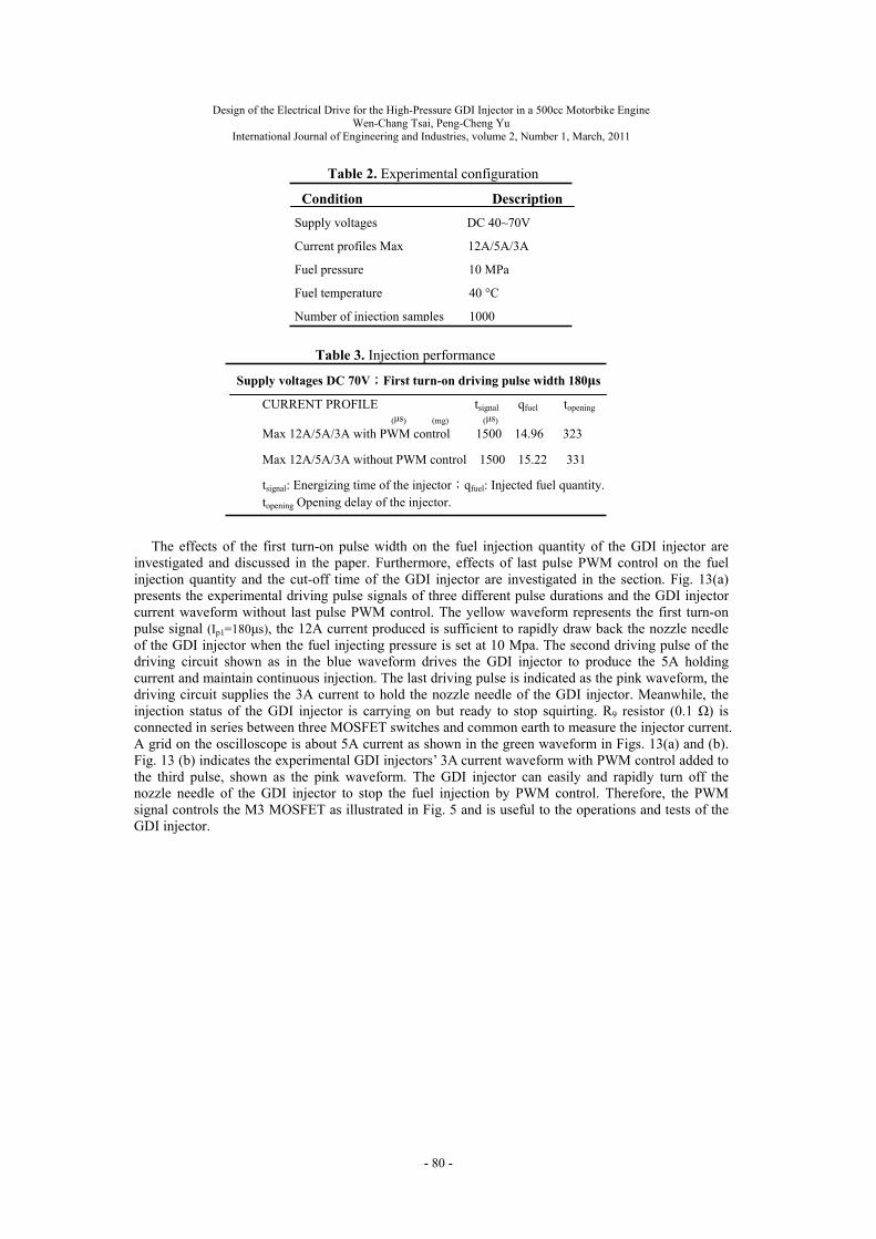
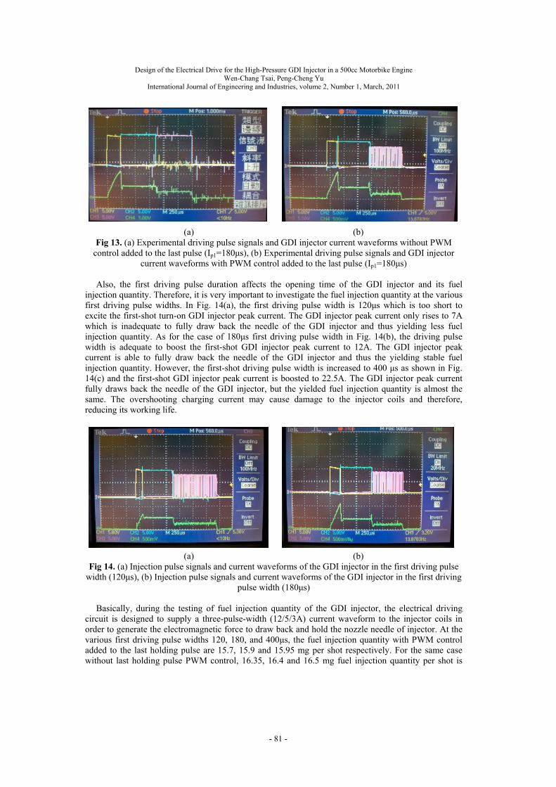
The effects of the first turn-on pulse width on the fuel injection quantity of the GDI injector are investigated and discussed in the paper. Furthermore, effects of last pulse PWM control on the fuel injection quantity and the cut-off time of the GDI injector are investigated in the section. Fig. 13(a) presents the experimental driving pulse signals of three different pulse durations and the GDI injector current waveform without last pulse PWM control. The yellow waveform represents the first turn-on pulse signal (Ip1=180μs), the 12A current produced is sufficient to rapidly draw back the nozzle needle of the GDI injector when the fuel injecting pressure is set at 10 Mpa. The second driving pulse of the driving circuit shown as in the blue waveform drives the GDI injector to produce the 5A holding current and maintain continuous injection. The last driving pulse is indicated as the pink waveform, the driving circuit supplies the 3A current to hold the nozzle needle of the GDI injector. Meanwhile, the injection status of the GDI injector is carrying on but ready to stop squirting. R9 resistor (0.1 Ω) is connected in series between three MOSFET switches and common earth to measure the injector current. A grid on the oscilloscope is about 5A current as shown in the green waveform in Figs. 13(a) and (b). Fig. 13 (b) indicates the experimental GDI injectors’ 3A current waveform with PWM control added to the third pulse, shown as the pink waveform. The GDI injector can easily and rapidly turn off the nozzle needle of the GDI injector to stop the fuel injection by PWM control. Therefore, the PWM signal controls the M3 MOSFET as illustrated in Fig. 5 and is useful to the operations and tests of the GDI injector.
Table 3. Injection performance
Supply voltages DC 70V;First turn-on driving pulse width 180μs
CURRENT PROFILE tsignal qfuel topening
(μs) (mg) (μs) Max 12A/5A/3A with PWM control 1500 14.96 323
Max 12A/5A/3A without PWM control 1500 15.22 331
tsignal: Energizing time of the injector;qfuel: Injected fuel quantity. topening Opening delay of the injector.
Table 2. Experimental configuration
Condition Description
Supply voltages DC 40~70V
Current profiles Max 12A/5A/3A
Fuel pressure 10 MPa
Fuel temperature 40 °C
Number of injection samples 1000
- 80 -
Design of the Electrical Drive for the High-Pressure GDI Injector in a 500cc Motorbike Engine Wen-Chang Tsai, Peng-Cheng Yu
International Journal of Engineering and Industries, volume 2, Number 1, March, 2011
(a) (b) Fig 13. (a) Experimental driving pulse signals and GDI injector current waveforms without PWM
control added to the last pulse (Ip1=180μs), (b) Experimental driving pulse signals and GDI injector current waveforms with PWM control added to the last pulse (Ip1=180μs)
Also, the first driving pulse duration affects the opening time of the GDI injector and its fuel
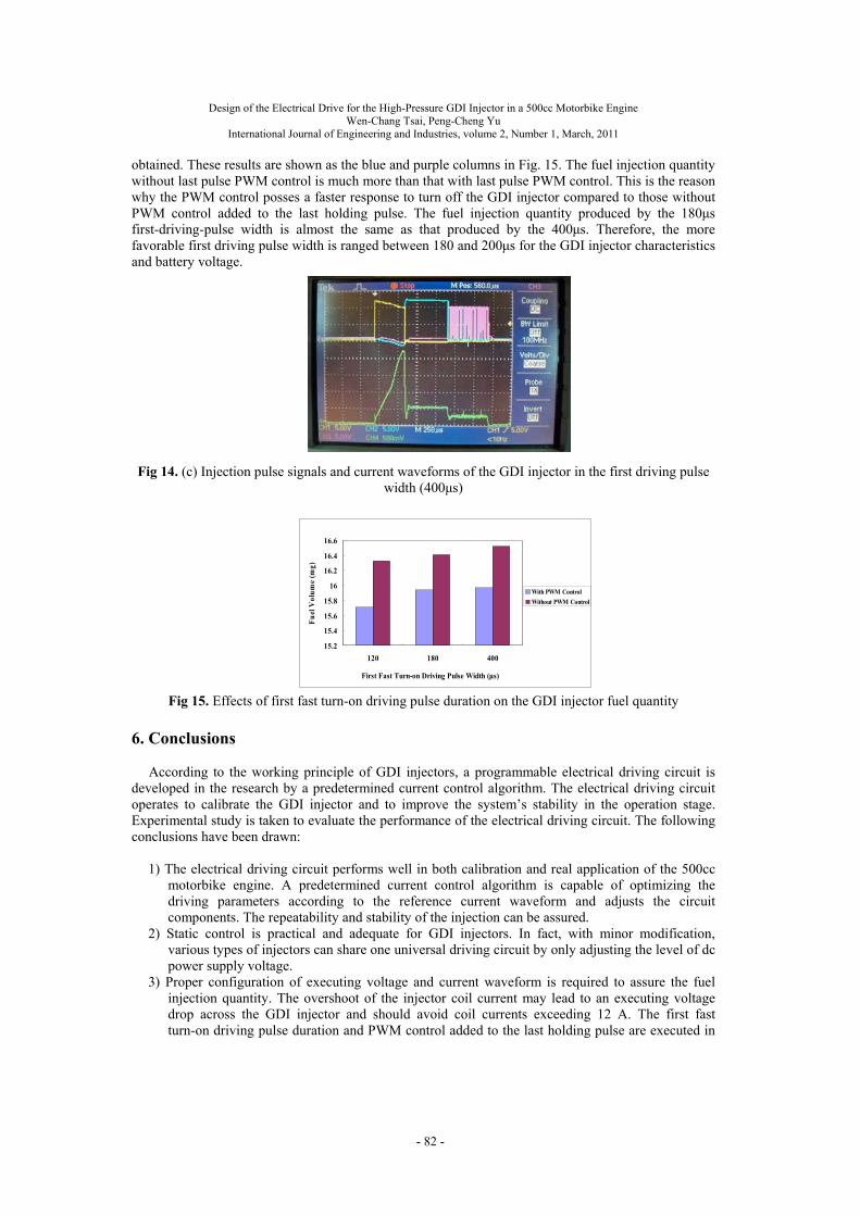
injection quantity. Therefore, it is very important to investigate the fuel injection quantity at the various first driving pulse widths. In Fig. 14(a), the first driving pulse width is 120μs which is too short to excite the first-shot turn-on GDI injector peak current. The GDI injector peak current only rises to 7A which is inadequate to fully draw back the needle of the GDI injector and thus yielding less fuel injection quantity. As for the case of 180μs first driving pulse width in Fig. 14(b), the driving pulse width is adequate to boost the first-shot GDI injector peak current to 12A. The GDI injector peak current is able to fully draw back the needle of the GDI injector and thus the yielding stable fuel injection quantity. However, the first-shot driving pulse width is increased to 400 μs as shown in Fig. 14(c) and the first-shot GDI injector peak current is boosted to 22.5A. The GDI injector peak current fully draws back the needle of the GDI injector, but the yielded fuel injection quantity is almost the same. The overshooting charging current may cause damage to the injector coils and therefore, reducing its working life.
(a) (b) Fig 14. (a) Injection pulse signals and current waveforms of the GDI injector in the first driving pulse
width (120μs), (b) Injection pulse signals and current waveforms of the GDI injector in the first driving pulse width (180μs)
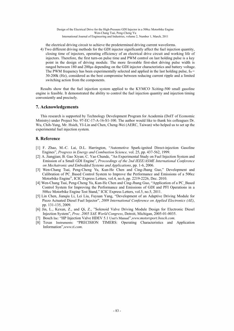
Basically, during the testing of fuel injection quantity of the GDI injector, the electrical driving
circuit is designed to supply a three-pulse-width (12/5/3A) current waveform to the injector coils in order to generate the electromagnetic force to draw back and hold the nozzle needle of injector. At the various first driving pulse widths 120, 180, and 400μs, the fuel injection quantity with PWM control added to the last holding pulse are 15.7, 15.9 and 15.95 mg per shot respectively. For the same case without last holding pulse PWM control, 16.35, 16.4 and 16.5 mg fuel injection quantity per shot is
- 81 -
Design of the Electrical Drive for the High-Pressure GDI Injector in a 500cc Motorbike Engine Wen-Chang Tsai, Peng-Cheng Yu
International Journal of Engineering and Industries, volume 2, Number 1, March, 2011
obtained. These results are shown as the blue and purple columns in Fig. 15. The fuel injection quantity without last pulse PWM control is much more than that with last pulse PWM control. This is the reason why the PWM control posses a faster response to turn off the GDI injector compared to those without PWM control added to the last holding pulse. The fuel injection quantity produced by the 180μs first-driving-pulse width is almost the same as that produced by the 400μs. Therefore, the more favorable first driving pulse width is ranged between 180 and 200μs for the GDI injector characteristics and battery voltage.
Fig 14. (c) Injection pulse signals and current waveforms of the GDI injector in the first driving pulse
width (400μs)
Fig 15. Effects of first fast turn-on driving pulse duration on the GDI injector fuel quantity
6. Conclusions
According to the working principle of GDI injectors, a programmable electrical driving circuit is developed in the research by a predetermined current control algorithm. The electrical driving circuit operates to calibrate the GDI injector and to improve the system’s stability in the operation stage. Experimental study is taken to evaluate the performance of the electrical driving circuit. The following conclusions have been drawn:
1) The electrical driving circuit performs well in both calibration and real application of the 500cc
motorbike engine. A predetermined current control algorithm is capable of optimizing the driving parameters according to the reference current waveform and adjusts the circuit components. The repeatability and stability of the injection can be assured.
2) Static control is practical and adequate for GDI injectors. In fact, with minor modification, various types of injectors can share one universal driving circuit by only adjusting the level of dc power supply voltage.
3) Proper configuration of executing voltage and current waveform is required to assure the fuel injection quantity. The overshoot of the injector coil current may lead to an executing voltage drop across the GDI injector and should avoid coil currents exceeding 12 A. The first fast turn-on driving pulse duration and PWM control added to the last holding pulse are executed in
15.2
15.4
15.6
15.8
16
16.2
16.4
16.6
120 180 400
First Fast Turn-on Driving Pulse Width (μs)
Fu
el V
olu
me
(mg)
With PWM Control
Without PWM Control
- 82 -
Design of the Electrical Drive for the High-Pressure GDI Injector in a 500cc Motorbike Engine Wen-Chang Tsai, Peng-Cheng Yu
International Journal of Engineering and Industries, volume 2, Number 1, March, 2011
the electrical driving circuit to achieve the predetermined driving current waveforms.
4) Two different driving methods for the GDI injector significantly affect the fuel injection quantity, closing time of injectors, operating efficiency of an electrical drive circuit and working life of injectors. Therefore, the first turn-on pulse time and PWM control on last holding pulse is a key point in the design of driving module. The more favorable first-shot driving pulse width is ranged between 180 and 200μs depending on the GDI injector characteristics and battery voltage. The PWM frequency has been experimentally selected and applied in the last holding pulse, fm = 30-200k (Hz), considered as the best compromise between reducing current ripple and a limited switching action from the components.
Results show that the fuel injection system applied to the KYMCO Xciting-500 small gasoline
engine is feasible. It demonstrated the ability to control the fuel injection quantity and injection timing conveniently and precisely.
7. Acknowledgements
This research is supported by Technology Development Program for Academia (DoIT of Economic
Ministry) under Project No. 97-EC-17-A-16-S1-100. The author would like to thank his colleagues Dr. Wu, Chih-Yung, Mr. Hsieh, YI-Lin and Chen, Cheng-Wei (AERC, Taiwan) who helped us to set up the experimental fuel injection system.
8. Reference
[1] F. Zhao, M.-C. Lai, D.L. Harrington, “Automotive Spark-ignited Direct-injection Gasoline
Engines”, Progress in Energy and Combustion Science, vol. 25, pp. 437-562, 1999. [2] A. Jiangjian; B. Gao Xiyan; C. Yao Chunde, ”An Experimental Study on Fuel Injection System and
Emission of a Small GDI Engine”, Proceedings of the 2nd IEEE/ASME International Conference on Mechatronic and Embedded Systems and Applications, pp. 1-6, 2006.
[3] Wen-Chang Tsai, Peng-Cheng Yu, Kun-He Chen and Cing-Jhang Guo,” Development and Calibration of PC_Based Control System to Improve the Performance and Emissions of a 500cc Motorbike Engine”, ICIC Express Letters, vol.4, no.6, pp. 2219-2226, Dec. 2010.
[4] Wen-Chang Tsai, Peng-Cheng Yu, Kun-He Chen and Cing-Jhang Guo, “Application of a PC_Based Control System for Improving the Performance and Emissions of GDI and PFI Operations in a 500cc Motorbike Engine Test Stand,” ICIC Express Letters, vol.5, no.5, 2011.
[5] Lin Chen, Jianqiu Li, Lei Liu, Fuyuan Yang, “Development of an Adaptive Driving Module for Piezo Actuated Diesel Fuel Injector”, 2009 International Conference on Applied Electronics (AE), pp. 131-135, 2009.
[6] Jin, L., Kexun, Z., and Qi, Z., ”Solenoid Valve Driving Module Design for Electronic Diesel Injection System”, Proc. 2005 SAE World Congress, Detroit, Michigan, 2005-01-0035.
[7] Bosch Inc: “HP Injection Valve HDEV 5.1 User's Manual”,www.motorsport.bosch.com. [8] Texas Instruments: “PRECISION TIMERS: Operating Characteristics and Application
Information”,www.ti.com.
- 83 -