Design of the Dubai Metro light rail viaducts—substructure · reinforced concrete abutments. Pier...
12
Proceedings of the Institution of Civil Engineers Bridge Engineering 162 June 2009 Issue BE2 Pages 63–74 doi: 10.1680/bren.2009.162 .2.63 Paper 800012 Received 15/02/2009 Accepted 06/03/2009 Keywords: bridges/concrete structures David A. Smith Group Manager— Special Structures, Atkins, Epsom, Surrey, UK Chris R. Hendy Head of Bridge Design and Technology, Atkins, Epsom, Surrey, UK Design of the Dubai Metro light rail viaducts—substructure D. A. Smith CEng, MICE and C. R. Hendy MA(Cantab), CEng, FICE The Dubai Metro light rail scheme is a flagship project in the United Arab Emirates which is currently one of the largest civil engineering projects under construction and, when completed, will be the longest fully automated rail system in the world. The first section of the rail system is due to be opened in September 2009. This paper describes the scheme outline and contractual set-up for the viaduct design and discusses the design and con- struction of the viaduct substructure. In particular, the design methodologies used for the piled foundations, single reinforced concrete columns and prestressed concrete pier heads are discussed as well as the design of elastomeric bearings that were used extensively for most of the viaduct spans. Seismic loading governed the design of many of the foundations and the seismic analysis and design methodology adopted is discussed, together with specific reinforcement detailing requirements. Rail– structure interaction analysis and design is also covered. Other critical design issues resolved included the fatigue performance of cranked reinforcement and the treat- ment of the onerous construction loading from overhead gantries used to erect the precast deck segments. 1. INTRODUCTION AND PROJECT BACKGROUND In July 2005, the Dubai Road and Transport Authority (RTA) awarded a design-and-build contract to the Dubai Rapid Link (DURL) consortium for the construction of the first and second stages of the Dubai Metro Red and Green Lines. The DURL consortium comprised the Japanese companies Mitsubishi Heavy Industries, Mitsubishi Corporation, Obayashi Corporation and Kajima Corporation together with Yapi Merkezi of Turkey. Construction of the infrastructure and stations was the responsibility of a joint venture between Kajima, Obayashi and Yapi Merkesi (Japan–Turkey–Metro joint venture or JTMjv). JTMjv appointed Atkins as their designer in 2006. This project organisation is illustrated in Figure 1. The Dubai Metro will be a driverless, fully automated metro network and will be the longest fully automated rail system in the world. Completion of the first section of the Red line is planned for September 2009, followed in 2010 with the first section of Green line. A further Blue line (along Emirates Road) and Purple line (an airport express route) are planned for subsequent years. The metro route map is illustrated in Figure 2, with a more detailed Red line route map shown in Figure 3. The £1?5 billion, 52 km long Red line connecting Rashidiya to Jebel Ali port comprises 42 km of elevated viaduct with 22 overground stations, 5?5 km of tunnels with four underground stations, 2?5 km of at-grade section and two depots. The £800 million, 24 km long Green line runs around the city centre connecting Festival City to the airport free zone and comprises 16 km of elevated viaduct with 12 overground stations and 7 km of tunnels with eight underground stations (of which two are shared with the Red line). This paper discusses the design and construction of the viaduct substructure. A further paper 1 covers the design and construc- tion of the viaduct superstructure. 2. VIADUCT FORM The proposed form of the viaduct was architecturally-led in appearance. Figure 4 gives an artist’s impression of the proposed viaduct at the conceptual design stage and much of this form was retained in the final detailed design. The viaduct superstructures were typically formed from U- shaped cross-sections as illustrated in Figures 5 and 6. The post- tensioned precast segmental deck segments were cast using either long-line or short-line moulds. The following superstructure forms, all of post-tensioned segmental construction, comprised the majority of the scheme. (a) One-span (single span) decks: simply-supported U-section decks constructed by the span-by-span method from an overhead gantry. (b) Two-span (twin span) continuous decks: U-section decks constructed by the span-by-span method from an overhead gantry and made continuous over internal supports by subsequent in situ concrete stitching of adjacent decks. (c) Three-span continuous decks: comprising a combination of U-section and box-section decks, erected by crane using the balanced cantilever method. (d) Station spans: three- or four-span continuous U-section decks constructed by the span-by-span method from an overhead gantry, subsequently made continuous over internal supports by stitching adjacent spans together. (e) Single-track decks: simply-supported U-section decks con- structed by the span-by-span method from an overhead gantry (similar to one-span decks). These decks are used at Bridge Engineering 162 Issue BE2 Design of the Dubai Metro light rail viaducts—substructure Smith N Hendy
Transcript of Design of the Dubai Metro light rail viaducts—substructure · reinforced concrete abutments. Pier...

Proceedings of the Institution ofCivil EngineersBridge Engineering 162June 2009 Issue BE2Pages 63–74doi: 10.1680/bren.2009.162 .2.63
Paper 800012Received 15/02/2009Accepted 06/03/2009
Keywords:bridges/concrete structures
David A. SmithGroup Manager—Special Structures,Atkins, Epsom, Surrey,UK
Chris R. HendyHead of Bridge Designand Technology, Atkins,Epsom, Surrey, UK
Design of the Dubai Metro light rail viaducts—substructure
D. A. Smith CEng, MICE and C. R. Hendy MA(Cantab), CEng, FICE
The Dubai Metro light rail scheme is a flagship project in
the United Arab Emirates which is currently one of the
largest civil engineering projects under construction and,
when completed, will be the longest fully automated rail
system in the world. The first section of the rail system is
due to be opened in September 2009. This paper
describes the scheme outline and contractual set-up for
the viaduct design and discusses the design and con-
struction of the viaduct substructure. In particular, the
design methodologies used for the piled foundations,
single reinforced concrete columns and prestressed
concrete pier heads are discussed as well as the design of
elastomeric bearings that were used extensively for most
of the viaduct spans. Seismic loading governed the design
of many of the foundations and the seismic analysis and
design methodology adopted is discussed, together with
specific reinforcement detailing requirements. Rail–
structure interaction analysis and design is also covered.
Other critical design issues resolved included the fatigue
performance of cranked reinforcement and the treat-
ment of the onerous construction loading from overhead
gantries used to erect the precast deck segments.
1. INTRODUCTION AND PROJECT BACKGROUND
In July 2005, the Dubai Road and Transport Authority (RTA)
awarded a design-and-build contract to the Dubai Rapid Link
(DURL) consortium for the construction of the first and second
stages of the Dubai Metro Red and Green Lines. The DURL
consortium comprised the Japanese companies Mitsubishi
Heavy Industries, Mitsubishi Corporation, Obayashi Corporation
and Kajima Corporation together with Yapi Merkezi of Turkey.
Construction of the infrastructure and stations was the
responsibility of a joint venture between Kajima, Obayashi and
Yapi Merkesi (Japan–Turkey–Metro joint venture or JTMjv).
JTMjv appointed Atkins as their designer in 2006. This project
organisation is illustrated in Figure 1.
The Dubai Metro will be a driverless, fully automated metro
network and will be the longest fully automated rail system in
the world. Completion of the first section of the Red line is
planned for September 2009, followed in 2010 with the first
section of Green line. A further Blue line (along Emirates Road)
and Purple line (an airport express route) are planned for
subsequent years. The metro route map is illustrated in Figure 2,
with a more detailed Red line route map shown in Figure 3.
The £1?5 billion, 52 km long Red line connecting Rashidiya to
Jebel Ali port comprises 42 km of elevated viaduct with 22
overground stations, 5?5 km of tunnels with four underground
stations, 2?5 km of at-grade section and two depots. The £800
million, 24 km long Green line runs around the city centre
connecting Festival City to the airport free zone and comprises
16 km of elevated viaduct with 12 overground stations and 7 km
of tunnels with eight underground stations (of which two are
shared with the Red line).
This paper discusses the design and construction of the viaduct
substructure. A further paper1 covers the design and construc-
tion of the viaduct superstructure.
2. VIADUCT FORM
The proposed form of the viaduct was architecturally-led in
appearance. Figure 4 gives an artist’s impression of the proposed
viaduct at the conceptual design stage and much of this form
was retained in the final detailed design.
The viaduct superstructures were typically formed from U-
shaped cross-sections as illustrated in Figures 5 and 6. The post-
tensioned precast segmental deck segments were cast using
either long-line or short-line moulds.
The following superstructure forms, all of post-tensioned
segmental construction, comprised the majority of the scheme.
(a) One-span (single span) decks: simply-supported U-section
decks constructed by the span-by-span method from an
overhead gantry.
(b) Two-span (twin span) continuous decks: U-section decks
constructed by the span-by-span method from an overhead
gantry and made continuous over internal supports by
subsequent in situ concrete stitching of adjacent decks.
(c) Three-span continuous decks: comprising a combination of
U-section and box-section decks, erected by crane using the
balanced cantilever method.
(d) Station spans: three- or four-span continuous U-section
decks constructed by the span-by-span method from an
overhead gantry, subsequently made continuous over
internal supports by stitching adjacent spans together.
(e) Single-track decks: simply-supported U-section decks con-
structed by the span-by-span method from an overhead
gantry (similar to one-span decks). These decks are used at
Bridge Engineering 162 Issue BE2 Design of the Dubai Metro light rail viaducts—substructure Smith N Hendy

depots and bifurcations of the main lines at the largest
stations
The viaduct substructures generally comprise reinforced con-
crete piers, with flared pier heads to support the deck, and
reinforced concrete abutments. Pier heads for the single span,
twin spans and station spans were constructed using thin precast
reinforced concrete shells which were infilled with in situ
concrete and prestressed in stages once erected on site. The pier
heads for the single track and three-span continuous internal
piers are of in situ reinforced concrete construction. All piers
and abutments were founded on large-diameter bored piles.
3. PILED FOUNDATION DETAILS
Dubai lies directly within the Arabian Desert and much of the
geology comprises fine sand overlying sandstone and mudstone.
The fine, upper sand layers consist mostly of crushed shell and
coral and are a combination of mobile dune sands and sabkha
deposits. These overlie calcarenitic, Aeolian deposits (sands,
weakly cemented sands and weak sandstone) and calcisilitite.
Beneath these, between around 20 and 40 m below existing
ground level, are Jurassic conglomerates, mudstones and
siltstones.
The geotechnical design parameters were derived by Atkins’
dedicated geotechnical team in Dubai and agreed with the
engineer’s representatives locally. Results of the extensive
ground investigations and their interpretation were collated into
several ground reports for typical sections along the full metro
route. The geotechnical design parameters in the soil and rock
layers were derived from Standard Penetration test (SPT-N)
values and unconfined compressive strength (UCS), respectively.
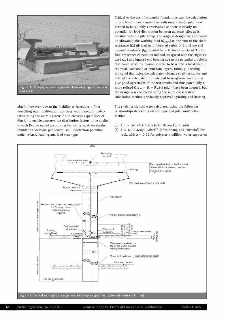
The vast majority of the viaduct spans are supported on single
circular reinforced concrete columns with flared pier heads to
support the decks, although a few portal structures are used in
specific locations. Most single columns are supported on bored
monopiles of diameter 2?2 and 2?4 m for speed of construction
and to minimise the footprint required for excavations in the
congested urban environment. Figure 7 shows a typical mono-
pile detail.
The use of large-diameter piles suited the interface with the
circular piers. Typically diameters of 1?75 or 2?0 m were used for
the piers supported on 2?2 m diameter piles, and 2?2 m for piers
supported on 2?4 m diameter piles. The connection detail
between the pile and pier was constructed like that for a pile
cap; the pile was broken down and pier starter bars introduced,
making allowance for piling tolerances. Figure 8 shows a typical
monopile foundation under construction with the column starter
bars in place and Figure 9 illustrates the alternative cranked
reinforcement connection details that were adopted, depending
on the relative sizes of pier and pile and the percentage
reinforcement content to minimise potential reinforcement
clashes due to piling tolerances.
The piles needed to be large enough to resist the significant
moments that are generated from lateral seismic loading (see
Sections 6 and 7 below) and from out-of-balance forces from
the deck due to horizontal alignment curvature, wind loading,
eccentric train loads and other effects. These moments increase
down the length of the pile towards a peak at the effective point
of fixity and reinforcement was provided and curtailed to suit
ClientGovernment of Dubai
Roads & Transport Authority
EngineerSystra Parsons
ContractorMitsubishi Corporation/Mitsubishi
Heavy IndustriesKajima—Obayashi—Yapi Merkezi
DesignerAtkins
Figure 1. Project organisation
N
Red line
Key
Green linePurple lineBlue line
Figure 2. Proposed route map
64 Bridge Engineering 162 Issue BE2 Design of the Dubai Metro light rail viaducts—substructure Smith N Hendy

the specific force and moment envelopes generated from a range
of load cases for each foundation.
The soil–structure behaviour for the pile design was determined
using readily available geotechnical software. Repute2 was used
as the main tool for each individual foundation. It allowed the
input of multiple strata parameters using a boundary element
method restricted by pile diameter and was able to model
dynamic behaviour. Its relative simplicity enabled a large
number of models to be analysed quickly and was therefore
highly suited to the tight design-and-build programme. Exact
locations of peak moment and force were not always easy to
UnionSquareR08
AI Rigga R07City Centre R06
AI Garhoud R05Airport Terminal 1 R04
Airport Terminal 3 R03Emirates R02
Rashidiya R01Rashidiya (main depot)
BurjumanR09
AI Karama R10
AI Jafiliya R11
Trade Centre R12Emirates Towers R13
Financial City R14
Burj Dubai R15
Business Bay R16
AI Quoz R17
Bruj AI Arab R18Mall of the Emirates R18A
AI Barsha'a R19
Tecom R20
Nakheel R21
Marina R22
Jumeira Lake Towers R23
Jumeira Island R24
Ibn Battuta R25
Dubal R26
Jebel Ali Industrial R27
Jafza/Limitless R28
Jebel Ali Port (auxiliary depot)
ToAbuDhabi
Dubai Creek
GULF
B07
B05
B06
B04
B02B03
B01
B00
B08
B09
B10
B11
B12
B13
B14
B15
B16
B17
B18
B18A
B19
B20
B21
B22
B23
B24
B25
B26
B27
B28
Sectio
n 3
Sect
ion
2
Section 1
Tunnel section T
Elevated stationsKey
Underground stationsStations by othersDepots
0 50010
0015
0020
0025
00 m
N
Figure 3. Red line route map
Figure 4. Conceptual viaduct form
Figure 5. Typical section of U-trough deck and pier head
Bridge Engineering 162 Issue BE2 Design of the Dubai Metro light rail viaducts—substructure Smith N Hendy
obtain, however, due to the inability to introduce a finer
modelling mesh. Calibration exercises were therefore under-
taken using the more rigorous finite-element capabilities of
Plaxis3 to enable conservative distribution factors to be applied
to each Repute model accounting for soil type, strata depths,
foundation location, pile length, soil liquefaction potential
under seismic loading and load case type.
Critical to the use of monopile foundations was the calculation
of pile length. For foundations with only a single pile, these
needed to be suitably conservative as there is clearly no
potential for load distribution between adjacent piles as is
possible within a pile group. The original design basis proposed
an allowable pile working load (Qallow) as the sum of the shaft
resistance (Qs) divided by a factor of safety of 2 and the end
bearing resistance (Qb) divided by a factor of safety of 3. The
final resistance calculation method, as agreed with the engineer,
used Qs/3 and ignored end bearing due to the potential problems
that could arise if a monopile were to bear into a local void in
the weak sandstone or mudstone layers. Initial pile testing
indicated that twice the calculated ultimate shaft resistance and
50% of the calculated ultimate end bearing resistance would
give good agreement to the test results and thus potentially a
more refined Qallow 5 Qs + Qb/2?5 might have been adopted, but
the design was completed using the more conservative
calculation method previously approved ignoring end bearing.
Pile shaft resistances were calculated using the following
relationships depending on soil type and pile construction
method
(a) 1?6 6 SPT-N + 6 kPa (after Decourt4) for soils
(b) k 6 (UCS design value)0?5 (after Zhang and Einstein5) for
rock, with k 5 0?35 for polymer-modified, water-supported
Figure 6. Prototype deck segment illustrating typical sectionand finish
Pier
Pier settingout point
Pier cap offset depth = 1440 nominalVaries with track vertical curvature
Pier cap level variesBearing
Pier head (precat shell, in situ infill)
Pier column
Typical drainage arrangement
Invert level variesWaterproofmembrane
Waterproof membrane totop of pile where exposedduring construction
Monopile foundation
Rockhead (varies)
Pile toe level varies
Pile/column splice length
3000
or
top
of c
olum
nif
less
Wat
erpr
oof
coat
ing
Varie
s20
0 ty
pica
l
Track reference level
Pier cap joint line
Pie
r ca
st c
olum
n he
ight
var
ies
Pile
leng
th v
arie
s
Flexible robust cables and weatherproofbox for stray current
monitoring whererequired
Existingground level
Drainage detailat stations
Foundationlevel
C.J.
Figure 7. Typical monopile arrangement for simply supported spans (dimensions in mm)
66 Bridge Engineering 162 Issue BE2 Design of the Dubai Metro light rail viaducts—substructure Smith N Hendy

pile shafts and k 5 0?25 for bentonite-supported pile shafts
as minimum values.
Several foundations for the simply supported spans required the
use of twin pile groups with a conventional pile cap for
spanning over existing large services where a monopile location
would clash. Additionally, four-pile pile groups with conven-
tional pile caps (illustrated in Figure 10) were adopted for the
internal piers of continuous two-span and three-span structures
and for simply supported spans where a monopile foundation
was not feasible due to very tall piers being required to support
spans with tight deck radii.
4. DESIGN METHODOLOGY FOR ULTIMATE LIMIT
STATE AND SERVICEABILITY LIMIT STATE
The design of the viaducts was based on BS 5400: Part 46 and
associated British Standards, with additional International
Standards used to supplement the scope in such areas as seismic
loading and detailing, and rail dynamic factors. The American
Concrete Institute technical design standard ACI 358.1R–927
was used to determine the dynamic factors to be applied to the
vertical train loading for deck longitudinal design for the
continuous spans. For the simply supported spans, the dynamic
factors were derived from bespoke dynamic analyses for the
respective span lengths. For transverse design, the recommended
dynamic factors of BS 5400: Part 28 for reduced rail loading (RL)
of 1?2 to 1?4 were verified again using a finite-element dynamic
analysis. In accordance with the ACI code, the dynamic impact
factors were not applied to the design of viaduct foundations,
but were included in the pier head and bearing design. The
maximum operating speed of the trains is intended to be 90 kph;
the maximum design speed was taken as 100 kph.
The usual BS 5400 load combinations from 1 to 5 were assessed
to determine critical design load effects. In addition, a sixth load
combination was added to cover seismic loading (see Section 6
below). Other specific load cases considered included temporary
loading from gantries (Section 5 below) and vehicular collision.
Figure 8. Construction of typical pier on a monopile foundation
2200ø pile
Pile
Pile
Outer bars(equally spaced)
Tubes for sonic integrity testto be provided in 25% of piles.
Outer spiral bar(100 minimum cover–AC–4(or below) ground classification)(125 minimum cover–AC–5ground classification)
Section A–A1:25
(Reinforcement varies)
070705
06
0202
0202
03 0304 04
01 01 01
Column reinforcementcast with pile
Weatherproof box forstray current monitoring
(where required)Flexible robust cable fixed to pile
reinforcement for stray currentmonitoring (where required)
Foundation level
1850
125
Ext
ent o
f hoo
p ba
rs
A A
1750ø
2200ø
Detail 1 at top of pile(Reinforcement varies)
Pier/pile
Column reinforcement
Alternative detail at base of pier
2200ø
1750(D)
01, 02
1112
1705
17
12
12
11
11
03, 04
05
Addtionalanti-crackbars includedat surface
Bar marks01,02,03 and 04cranked inwardsby up to 75 mmat a slope of1 in 10Cranked barsprovide forgreater pilingtolerances
400
100
900
01, 02
03, 04
Pile reinforcement
Figure 9. Typical pier–pile connection details (dimensions in mm)
Bridge Engineering 162 Issue BE2 Design of the Dubai Metro light rail viaducts—substructure Smith N Hendy

Typically, class C32/40 was used for the pier and pile cap
concrete. Class C32/40 concrete was also used for the piles, but
to account for possible weakening during the placement (under
bentonite or polymer-modified suspension fluid) the cube
strength design value used was reduced by 10 MPa. All
reinforcement used in the substructure design was high yield,
type 2 deformed bars with a yield stress of 460 MPa. The
aggressive ground conditions meant that durability considera-
tions were paramount. As a result, additional waterproofing was
applied to the top 5 m of all piles to improve resistance to
chloride attack and pile cover to reinforcement of 120 mm was
used to improve resistance to sulfate attack. Generally crack
widths (under combination 1 loads) were limited to 0?2 mm.
Fatigue of reinforcement was also a critical design consideration
in some locations (see Section 8 below).
The construction programme called for the initial design of over
1200 unique foundations in the first 9 months of design to take
the viaduct construction off the critical path. This was achieved
through automation of the bulk of the design process and the
use of conservative simplifying assumptions in the early stages
of design. As the team got ahead of the programme, the
conservatism was removed from the process and more refined
calculation methods introduced into the automated procedures
to optimise the designs for the foundations yet to be
constructed.
The design programme capitalised on the locations of the UK-
based structures team and the Dubai-based alignment team,
which handled setting out and local issues such as utility
diversions. Advantage was made of the staggered weekends
between Dubai and the UK; the alignment of a given section was
distributed at the start of the UK week and the appropriate design
data added and sent back to Dubai at the end of the UK week.
Coupled with the automation process developed, this allowed a
peak output of 100 bespoke designs per week to be achieved.
5. DESIGN DURING CONSTRUCTION: GANTRY
LOADING
The majority of the simply supported decks and two-span
continuous decks were constructed by overhead gantries
(illustrated in Figures 11 and 12). The temporary loading from
the various gantries used on the scheme was defined by the
temporary works subcontractor, VFR (a consortium comprising
VSL, Freyssinet and Rizzani De Eccher), appointed to undertake the
Track reference level
Pier setting out point
Pier
Pier cap jointline
Flexible robust cables and weatherproofbox for stray current monitoring whererequired.
Removable cap 1000 × 500 × 300stone (to preventscour)
Waterproof membrane
Invert level varies
Typical drainage arrangement
Bearing
Pier head (precat shell,in situ infill)
100 min
Rockhead (varies)
50
2050
500
(typ
ical
ly)
Wat
erpr
oof
coat
ing
3000
or
top
ofco
lum
n if
less
C.J.
75 blinding
1400øpiles
1400øpiles
Top of pilecap
2200(D)
Level varies
Pile cut-offlevel
Pile toe level varies
Existingground level
Pie
r ca
st c
olum
n he
ight
var
ies
Pile
leng
th v
arie
s
Figure 10. Typical four-pile pile group arrangement for internal piers (dimensions in mm)
68 Bridge Engineering 162 Issue BE2 Design of the Dubai Metro light rail viaducts—substructure Smith N Hendy
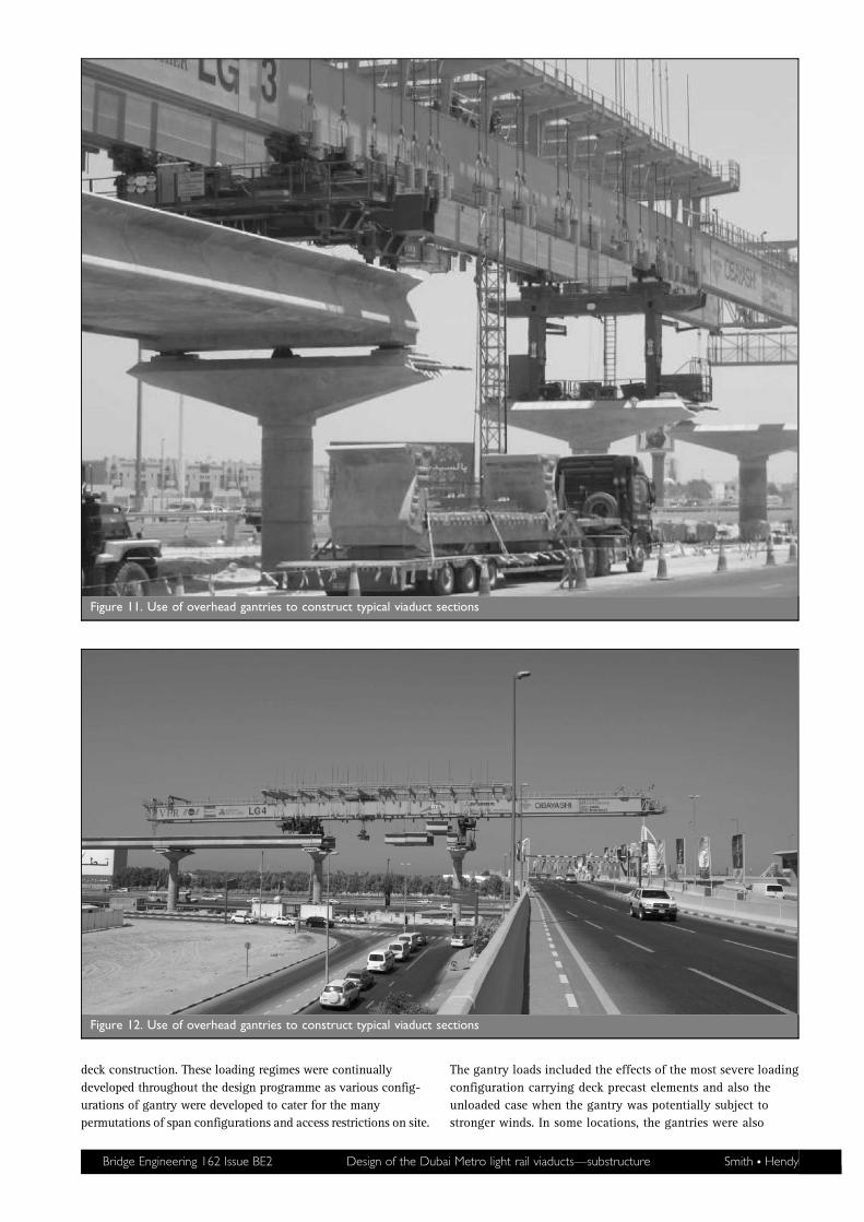
deck construction. These loading regimes were continually
developed throughout the design programme as various config-
urations of gantry were developed to cater for the many
permutations of span configurations and access restrictions on site.
The gantry loads included the effects of the most severe loading
configuration carrying deck precast elements and also the
unloaded case when the gantry was potentially subject to
stronger winds. In some locations, the gantries were also
Figure 11. Use of overhead gantries to construct typical viaduct sections
Figure 12. Use of overhead gantries to construct typical viaduct sections
Bridge Engineering 162 Issue BE2 Design of the Dubai Metro light rail viaducts—substructure Smith N Hendy

required to travel over previously constructed (by the balanced
cantilever method) three-span continuous decks and the
temporary effects of these conditions needed to be designed for.
Precast deck segments were mostly delivered to their required
location at ground level, but in some locations where access was
more difficult, some segments were delivered over the
previously constructed deck using special transporters. The
additional load effects from these cases on permanent works
also needed to be considered in the detailed design.
For the substructure, the temporary construction load cases were
generally not governing for the pier and pile designs as they
were typically less onerous than the seismic design effects. The
design of the pier heads however, was extremely sensitive to the
gantry loads (and in particular to the torsion induced) as
discussed in Section 9 below.
6. SEISMIC DESIGN METHODOLOGY AND
DETAILING
Seismically, Dubai is in a very stable zone. The nearest seismic
fault line, the Zargos Fault, is 120 km from the UAE and is unlikely
to have any seismic impact on Dubai. Nevertheless, the employer’s
requirements specified that the viaducts should be designed for
earthquakes in accordance with AASHTO LRFD,9 classing the
viaducts as ‘essential’, the site as Zone 2 and using an acceleration
coefficient of 0?12. The site coefficients were determined in
accordance with AASHTO LRFD on the basis of the relevant
geological profile and geotechnical data for the foundations. Soil
profile types I and II were found to be appropriate for the entire
route, giving site coefficients of 1?0 and 1?2 respectively (modified
to 1?0 and 1?5, respectively, where the flexibility of the
elastomeric bearings was included in the seismic analysis).
AASHTO LRFD was only used to determine the load effects from
a seismic event. Once obtained, these effects were combined
with the other appropriate coexistent load effects and the
foundations designed in accordance with the resistance rules of
BS 5400:Part 4 as for other non-seismic load cases.
In general, the single-mode elastic method was used and the
fundamental period of vibration was determined by modelling
individual piers using the computer software lusas10 as
described in Section 7 below. Multimodal analyses were also
used for continuous structures and irregular single-span
arrangements (see Section 7). The horizontal elastic seismic
response coefficient for a given natural period of vibration, Csm,
was obtained from AASHTO LFRD
Csm ~1:2AS
T2=3m
ƒ 2:5A
where Tm is the period of vibration of the mth mode (in s), A is
the acceleration coefficient and S the site coefficient.
There were no contract requirements for seismic serviceability
performance so columns were designed to form plastic hinges at
their bases under a seismic event at the ultimate limit state.
Potential plastic hinge zones were confined to the base of the
piers and the top of the piles so that the substructure could be
readily inspected for damage after an earthquake. Plastic hinges
were promoted in these regions by dividing the elastic seismic
design forces by appropriate response modification factors, R,
for the respective elements (based on the provisions given in
AASHTO LRFD) with
(a) R 5 1?5 for elastomeric bearings where account of the
bearing flexibility had been included in the natural
frequency analysis
(b) R 5 2?0 for continuous structures with mechanical bearings.
The onset of plasticity controls the magnitude of forces that can
be transmitted to the rest of the structure, which is particularly
beneficial in the event of an extreme earthquake whose
magnitude exceeds the design value. However, over-strength of
the hinge zone in bending could lead to greater forces being
attracted than expected. For such cases, it is important that the
piers have adequate shear strength to still enable a ductile
response to develop, rather than permit a brittle shear failure to
occur. To guard against such failure, the piers were designed for a
shear force that corresponds to the achievement of the over-
strength moment of resistance in the plastic hinge zone at the
base of the piers. AASHTO recommends using an over-strength
factor of 1?3 to account for the difference between mean material
properties and 5% lower fractile values. In addition, further over-
strength is provided because of the use of partial material factors.
These need to be removed to determine the potential difference in
strength between design values and realistic in situ values. The
over-strength factor to account for the removal of the material
partial factors will be between the values of 1?15 and 1?5 (the BS
5400: Part 4 values for steel and concrete, respectively). For the
typical column reinforcement percentages used for Dubai Metro,
this factor was approximately 1?22.
To ensure that the plastic hinge zone is confined to the base of
the pier, the flexural design of the pier above the plastic hinge
was based on bending moments which are consistent with the
over-strength moment of resistance in the plastic hinge zone
and the corresponding over-strength shear force.
Superstructure–pier connection forces were based on the lesser
of the elastic seismic design forces divided by a response
modification factor, R, of 1?0 or the shear force that corresponds
with the over-strength moment of resistance in the plastic hinge
zone at the base of the pier. This was applied to the bearing
design too.
Reinforcement detailing for the viaducts was generally in
accordance with BS 5400: Part 4. However, special additional
requirements for seismic detailing were taken from AASHTO
LRFD. In particular there is a need to ensure that the piers have
adequate ductility as discussed above. This was achieved by
providing adequate transverse reinforcement in the potential
plastic hinge zones, to prevent buckling of the longitudinal
reinforcement and to provide confinement to the concrete core.
This confinement reinforcement was continued into the body of
the pile caps, where used, in accordance with the code.
Transverse reinforcement could be formed by either spiral or
hoop reinforcement, provided that conventional laps were not
used in the plastic hinge zone and hoop reinforcement was
anchored into the body of the column with adequate hooks. The
latter would have given increased congestion and reduced space
for concrete vibrators, thus spiral reinforcement was used for the
majority of foundations. Lapping of longitudinal reinforcement
70 Bridge Engineering 162 Issue BE2 Design of the Dubai Metro light rail viaducts—substructure Smith N Hendy
was also kept outside the potential plastic hinge zones so as not
to compromise ductility and over-strength shear and moment
design away from the plastic hinge zone.
7. SEISMIC ANALYSIS
The seismic analyses of the straight sections of simply supported
spans were carried out in accordance with AASHTO LRFD for
multi-span bridges with ‘regular’ spans provided they met the
span ratio and pier stiffness criteria even though the number of
spans exceeded six. The single-mode elastic analysis uniform
load method was used. Other structures were designed using a
multimodal response spectrum analysis in which the presence of
the rails was ignored.
All of the seismic analyses were performed using several finite-
element beam and shell models analysed in lusas. The models
included the pile supports either with equivalent cantilevers or
complete piles with soil springs. Equivalent cantilevers were
determined from the results of the soil–structure interaction
analyses. This was an iterative process to ensure that the
stiffness derived was appropriate to the mean load level.
Accelerations were determined using the seismic response
spectrum defined in AASHTO LRFD. The site coefficients used in
the response spectrum definition were dependent on the bearing
type used as noted in Section 6 above.
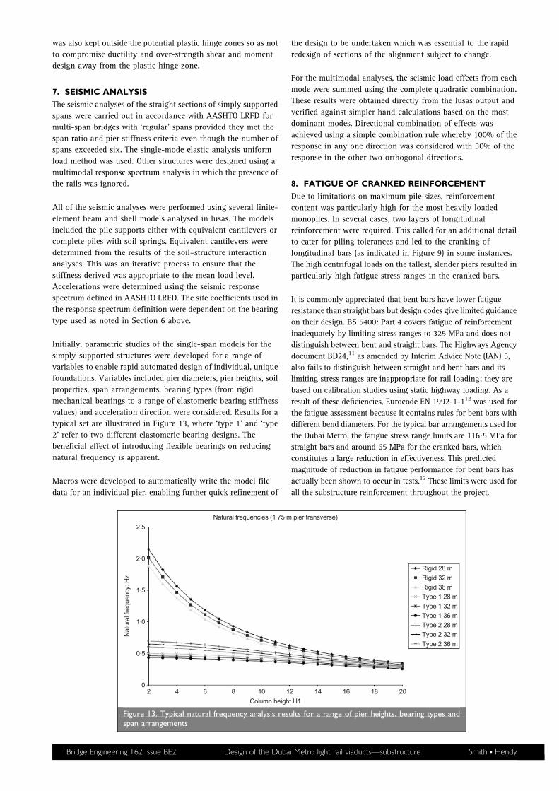
Initially, parametric studies of the single-span models for the
simply-supported structures were developed for a range of
variables to enable rapid automated design of individual, unique
foundations. Variables included pier diameters, pier heights, soil
properties, span arrangements, bearing types (from rigid
mechanical bearings to a range of elastomeric bearing stiffness
values) and acceleration direction were considered. Results for a
typical set are illustrated in Figure 13, where ‘type 1’ and ‘type
2’ refer to two different elastomeric bearing designs. The
beneficial effect of introducing flexible bearings on reducing
natural frequency is apparent.
Macros were developed to automatically write the model file
data for an individual pier, enabling further quick refinement of
the design to be undertaken which was essential to the rapid
redesign of sections of the alignment subject to change.
For the multimodal analyses, the seismic load effects from each
mode were summed using the complete quadratic combination.
These results were obtained directly from the lusas output and
verified against simpler hand calculations based on the most
dominant modes. Directional combination of effects was
achieved using a simple combination rule whereby 100% of the
response in any one direction was considered with 30% of the
response in the other two orthogonal directions.
8. FATIGUE OF CRANKED REINFORCEMENT
Due to limitations on maximum pile sizes, reinforcement
content was particularly high for the most heavily loaded
monopiles. In several cases, two layers of longitudinal
reinforcement were required. This called for an additional detail
to cater for piling tolerances and led to the cranking of
longitudinal bars (as indicated in Figure 9) in some instances.
The high centrifugal loads on the tallest, slender piers resulted in
particularly high fatigue stress ranges in the cranked bars.
It is commonly appreciated that bent bars have lower fatigue
resistance than straight bars but design codes give limited guidance
on their design. BS 5400: Part 4 covers fatigue of reinforcement
inadequately by limiting stress ranges to 325 MPa and does not
distinguish between bent and straight bars. The Highways Agency
document BD24,11 as amended by Interim Advice Note (IAN) 5,
also fails to distinguish between straight and bent bars and its
limiting stress ranges are inappropriate for rail loading; they are
based on calibration studies using static highway loading. As a
result of these deficiencies, Eurocode EN 1992-1-112 was used for
the fatigue assessment because it contains rules for bent bars with
different bend diameters. For the typical bar arrangements used for
the Dubai Metro, the fatigue stress range limits are 116?5 MPa for
straight bars and around 65 MPa for the cranked bars, which
constitutes a large reduction in effectiveness. This predicted
magnitude of reduction in fatigue performance for bent bars has
actually been shown to occur in tests.13 These limits were used for
all the substructure reinforcement throughout the project.
2.5
2.0
1.5
1.0
0.5
02 4 6 8 10
Column height H1
Rigid 28 mRigid 32 mRigid 36 mType 1 28 mType 1 32 mType 1 36 m
Type 2 32 mType 2 36 m
Type 2 28 m
12 14 16 18 20
Nat
ural
freq
uenc
y: H
z
Natural frequencies (1.75 m pier transverse)
Figure 13. Typical natural frequency analysis results for a range of pier heights, bearing types andspan arrangements
Bridge Engineering 162 Issue BE2 Design of the Dubai Metro light rail viaducts—substructure Smith N Hendy

In order to comply with these relatively low permissible limits,
the fatigue stress ranges were calculated from the likely mix of
actual train loads rather than from the full characteristic loading
used in the static design. For the predicted 20 million load cycles
within the design life, the latter would be too onerous. Realistic
operating train speeds were also used in the calculation of
centrifugal forces, rather than the enhanced design speed used
for ultimate limit state calculations.
The above approach was enough to justify the use of cranked
bar details apart from one or two worst cases where separate
bespoke details were developed without bending the bars.
9. PIER HEAD DESIGN
The design and construction of the pier heads was subcontracted
by JTMjv to ETiC, but Atkins retained the design responsibility
and was instrumental in developing the final design solutions to
satisfy the particularly onerous temporary load conditions. The
design interfaces were complicated further with close coordina-
tion required between the designers, the bearing suppliers and
VFR, who were responsible for the supply of gantry loads and
erection sequences. Iteration with the bearing design was
subsequently simplified by landing the decks on temporary
supports before jacking onto permanent bearings after the
gantries had moved on to erect other spans (see Section 10 below).
The appearance of the pier heads was architecturally led (see
Figure 14) and required precast outer shells to achieve the desired
finish consistently. The outer shells were cast using steel moulds
and stored with the deck segments in the dedicated casting yard at
Jebel Ali. The outer shells comprised thin-walled, reinforced
concrete sections which could be transported to site when required,
before being in filled with in situ concrete and prestressed in
controlled stages on site as the permanent load was added.
Designed initially for the permanent condition only, the pier
heads had several shear and torsion deficiencies identified under
construction load cases due to the high eccentricity of the
temporary gantry loading. In this temporary condition, all the
self-weight of both spans was applied on one side of the pier
head through temporary supports (Figure 15). In the final
condition, the load from each span is more balanced.
For the temporary condition, the maximum shear and torsion
could not be resisted by either the shell or the in situ infill
concrete alone and thus the pier head had to be designed to
mobilise a contribution from both the shell and the infill, despite
minimal interface reinforcement being provided between the two.
To achieve an adequate design without modifying the pier head
moulds, which had already been fabricated, several departures
from BS 5400: Part 4 were required. In particular, the inclined
components of prestressing force and compression chord force
were included in the shear resistance, the tensile serviceability
limit state stresses during construction were limited to class 2
Figure 14. Typical pier head arrangement
Figure 15. High eccentricity of temporary loading fromoverhead gantries
72 Bridge Engineering 162 Issue BE2 Design of the Dubai Metro light rail viaducts—substructure Smith N Hendy

limits, rather than the.1?0 MPa limit stipulated, and stresses
during bearing replacement were limited to class 3 limits
following agreement to this relaxation by the client.
10. BEARING DESIGN
The majority of the single-span decks are supported on
elastomeric bearings. Pot bearings have been used for all the
continuous structures for both internal supports and end
supports and therefore also the ends of the single spans sharing
pier heads with continuous spans.
The philosophy for the design of the elastomeric bearings was
complicated by two opposing design objectives. The bearings
needed to be stiff enough to comply with the continuous rail
deflection limits (of International Union of Railways technical
standard UIC 776-314) and strong enough to withstand the vertical
and horizontal loads. However, they needed to be flexible enough
to minimise the seismic forces attracted to the substructure since
lower stiffness leads to reduced natural frequencies and reduced
lateral accelerations. The range of adequate elastomeric bearings
that could satisfy these requirements was particularly narrow and
also very sensitive to span arrangements.
Typically, bearings of around 600 mm by 650 mm to 750 mm by
750 mm in plan and 150 mm to 210 mm tall were adopted. The
elastomeric bearings were generally designed in accordance with
BS 5400: Part 9,15 but this only gives guidance on design at the
serviceability limit state and does not cover ultimate limit state
design which was required for the usually critical seismic load cases.
The similar design rules given in BS EN 1337-316 were therefore
used to check the adequacy of the bearings at ultimate limit state.
For speed of construction and simplicity, the contractor was
keen to avoid any mechanical fixing of the elastomeric bearings
to the deck. Consequently the bearings were designed to be
placed dry between the deck and the pier head plinths and to
rely on friction as the sole means of lateral restraint. Where
transverse forces on the elastomeric bearings exceeded 10% of
the vertical load (as occurred for all locations), the bearings were
fitted with an interfacing chequered plate to provide a minimum
coefficient of friction of 0?5 between mating surfaces. This
attachment was capable of carrying the entire transverse load.
Since reliance was placed on friction as the sole means of
restraint against lateral seismic loads, a coexistent vertical
acceleration was considered in the design of the elastomeric
bearings, despite not being specified in the employer’s require-
ments. This acceleration was derived from a response spectrum
similar to that used for the horizontal accelerations, but with
values equal to two-thirds of the horizontal ones.
As the design of the elastomeric bearings was tailored to the
permanent condition, there was little capacity left to accommo-
date deflections, rotations and translations that would be locked
into the bearings due to the use of launching gantries and the
construction sequences adopted. Consequently, the majority of the
decks had to be landed on temporary supports during the initial
erection by gantry before they could be subsequently jacked up
onto their permanent bearings when the gantry had moved on.
Although not ideal for construction, this solution had benefit in
reducing the temporary load effects in the pier heads and was thus
adopted as a compromise to overcome several problems.
11. RAIL–STRUCTURE INTERACTION
As discussed above, the viaducts comprise a combination of
simply supported spans on elastomeric bearings and continuous
spans with fixed and free guided sliding pot bearings. The rails
are continuously welded across all the decks and deck joints and
are connected to the deck by regular track fixings, thus the rails
interact with the deck causing relative movements to occur
which induce stresses in the rails and forces in the deck.
The temperature range of the continuous welded rail (CWR) was
considered relative to its neutral setting temperature of 40 ¡
37 C̊ and the maximum and minimum rail temperatures which
were assumed to be +75 and +3 C̊, respectively. This gave CWR
extreme ranges of +38 C̊ and 240 C̊. The rail–structure
interaction (RSI) temperature range is governed by the change of
structure temperature relative to deck temperature at the time of
installation of the rail. Based on the specified design tempera-
ture ranges, the maximum and minimum deck temperatures
were assumed to be +55 to +5 C̊. It was further assumed that the
rails were fixed to the deck at deck temperatures between +20
and +40 C̊, which gave maximum and minimum temperature
ranges of +35 C̊ and 235 C̊. This corresponds with the
International Union of Railways technical standard UIC 774-
3R17 requirements of maximum and minimum bridge tempera-
ture ranges of ¡35 C̊. The build-up of CWR forces in the rail
was considered at points where rail breather joints are located
and for the case of a rail break. For viaducts with horizontal
curvature the effects of the radial forces arising from the full
CWR forces were considered.
The rails were checked against the recommendations of UIC 774-3.
These requirements limit the stress ranges due to this RSI
behaviour to prescribed values. The checks are only necessary for
in-service conditions, thus no analysis of rail forces was under-
taken for seismic events. Checks were, however, also made on the
additional stresses induced in the rails due to the end rotations of
the decks and the differential vertical and transverse movements
permitted due to the flexibility of the bearings. The values of these
additional forced rail displacements and rotations were considered
by the trackwork designers in the final rail design.
The rail–structure interaction behaviour is non-linear because
the track fixings allow slip to occur with an elasto-plastic
relationship illustrated in Figure 16. The decks also interact with
each other through the continuous rails and the rail connections
and so the overall global behaviour is complex. The effects can
14
12
10
8
6
4
2
0
0.0
10.5 kN/assembly
0.65 mm
0.5 1.0 1.5 2.0 2.5
Load
: kN
_ 2
Figure 16. Track fixings slip characteristics
Bridge Engineering 162 Issue BE2 Design of the Dubai Metro light rail viaducts—substructure Smith N Hendy

be rationalised, however, such that simplified approximate
methods can be used initially to identify the most critical
viaduct lengths which required further detailed analysis.
The global behaviour was analysed using two-dimensional
models of both the structure and rails to examine the longitudinal
load distributions. The rails were modelled as beam elements with
non-linear springs connecting them to the deck. The out-of-
balance effects of different adjacent span lengths were analysed
using a simple elastic two-dimensional model of at least five
spans either side of the design pier in order to quantify the forces
on the bearings and piers. This approach was also used for vertical
load effects, seismic loading and traction and braking.
A series of simplified spreadsheet approaches to estimating the
rail–structure interaction forces and for checking compliance
against the UIC code requirements was developed. Where the
simplified checks showed borderline cases, the more sophisti-
cated non-linear analysis was used to demonstrate adequacy. In
some instances, this required the flexibility of the fixed piers
and their foundations to be included in the non-linear models.
Changes to the overall viaduct setting-out continued throughout
the construction process where previously undisclosed existing
utility locations were identified requiring span arrangements to
be adjusted. The development of the simplified approaches to
RSI analysis enabled a rapid decision to be obtained on the
impact such setting-out variations had on the overall RSI
conclusions without the need to undertake more complex
analysis every time the span arrangements altered.
In addition to the RSI analysis, absolute and relative displace-
ment checks were carried out against the UIC 774-3 require-
ments for braking, acceleration and deck end rotation due to
vertical loading. The relative vertical deflection across adjacent
decks at rail locations was limited to 3 mm.
ACKNOWLEDGEMENTS
This paper is published with the permission of the Dubai RTA and
Naramichi Oba san of the JTMjv. The authors would also like to
acknowledge Atkins Project Director, John Newby, and his
management team for their excellent coordination of the
numerous design parties. Parts of this paper were presented at and
published in the proceedings of the NCBC 2008 Concrete Bridge
Conference ‘HPC: Safe, Affordable and Efficient’ in St. Louis in
May 200818 and the international symposium ‘Concrete:
Construction’s Sustainable Option’ in Dundee in July 2008.19
REFERENCES
1. SMITH D. A., HEWSON N. R. and HENDY C. R. Design of the
Dubai Metro Light Rail Viaducts—superstructure.
Proceedings of the Institution of Civil Engineers—Bridge
Engineering, 2009, 162, No. 2, 55–62.
2. REPUTE v1.54, Geocentrix Ltd, Banstead, Surrey, 2007.
3. PLAXIS 2D v8.6, Plaxis BV, the Netherlands, 2007.
4. DECOURT L. Prediction of load–settlement relationships for
foundations on the basis of the SPT-T. Proceedings of the
Leonardo Zeevaert Conference, National Autonomous
University of Mexico, Mexico, 1995, pp. 85–104.
5. ZHANG L. and EINSTEIN H. H. End bearing capacity of
drilled shafts in rock. Journal of Geotechnical and
Geoenvironmental Engineering, 1998, 124, No. 7, 574–584.
6. BRITISH STANDARDS INSTITUTION. Steel, Concrete and Composite
Bridges, Part 4—Code of Practice for Design of Concrete
Bridges. BSI, London, 1990, BS 5400.
7. AMERICAN CONCRETE INSTITUTE. Analysis and Design of
Reinforced and Prestressed Concrete Guideway Structures
(Chapter 3—Loads, p. 358. 1R-15). ACI Committee 311,
Michigan, 1992, ACI 358.1R-92.
8. BRITISH STANDARDS INSTITUTION. Steel, Concrete and Composite
Bridges, Part 2—Specification for Loads. BSI, London, 1978,
BS 5400.
9. AMERICAN ASSOCIATION OF STATE HIGHWAY AND TRANSPORTATION
OFFICIALS. LRFD Bridge Design Specifications, 3rd edn.
AASHTO, Washington, DC, 2004.
10. LUSAS Finite Element Analysis Software, Finite Element
Analysis Ltd, Kingston-upon-Thames, 2007.
11. HIGHWAYS AGENCY. Design Manual for Roads and Bridges,
BD24—The Design of Concrete Highway Bridges and
Structures—Use of BS 5400: Part 4: 1990. Highways
Agency, London, 1992.
12. BRITISH STANDARDS INSTITUTION. Eurocode 2: Design of Concrete
Structures—Part 2-1-1: General Rules and Rules for
Buildings. BSI, London, 2004, BS EN 1992-1-1.
13. BENNETT E. W. Fatigue tests of spliced reinforcement in
concrete beams. In Fatigue of Concrete Structures, ACI
Publication SP-75 (SHAH S. P. (ed.)). American Concrete
Institute, Detroit, 1982, ACI SP-75.
14. INTERNATIONAL UNION OF RAILWAYS TECHNICAL STANDARD.
Deformation of Bridges. UIC, Paris, 1989, UIC 776–3.
15. BRITISH STANDARDS INSTITUTION. Steel, Concrete and Composite
Bridges, Part 9—Bridge Bearings. BSI, London, 1983, BS
5400.
16. BRITISH STANDARDS INSTITUTION. Structural Bearings,
Part 3—Elastomeric Bearings. BSI, London, 2005, BS EN
1337–3.
17. INTERNATIONAL UNION OF RAILWAYS TECHNICAL STANDARD. Track/
bridge Interaction, Recommendations for Calculations, 2nd
edn. UIC, Paris, October 2001, UIC 774–3.
18. SMITH D. A. and HENDY C. R. Design of the Dubai Metro Light
Rail viaducts—substructure, 2008. Proceedings of Concrete
Bridge Conference HPC: Safe, Affordable and Efficient, 4–6
May 2008, St. Louis, MO, National Concrete Bridge Council,
c/o Portland Cement Association, Skokie, IL.
19. SMITH D. A. and HENDY C. R. Design of the Dubai Metro Light
Rail bridge viaducts—substructures. In Concrete Durability:
Achievement and Enhancement (DHIR R. K., HARRISON T. A.,
ZHENG L. and KANDASAMI S. (eds)). IHS BRE Press, Watford,
UK, 2008, pp. 781–800.
What do you think?To comment on this paper, please email up to 500 words to the editor at [email protected]
Proceedings journals rely entirely on contributions sent in by civil engineers and related professionals, academics and students. Papersshould be 2000–5000 words long, with adequate illustrations and references. Please visit www.thomastelford.com/journals for authorguidelines and further details.
74 Bridge Engineering 162 Issue BE2 Design of the Dubai Metro light rail viaducts—substructure Smith N Hendy